WO2016067772A1 - 制御装置、制御システム、解析装置、粒子分取装置、制御方法及び層流制御プログラム - Google Patents
制御装置、制御システム、解析装置、粒子分取装置、制御方法及び層流制御プログラム Download PDFInfo
- Publication number
- WO2016067772A1 WO2016067772A1 PCT/JP2015/075966 JP2015075966W WO2016067772A1 WO 2016067772 A1 WO2016067772 A1 WO 2016067772A1 JP 2015075966 W JP2015075966 W JP 2015075966W WO 2016067772 A1 WO2016067772 A1 WO 2016067772A1
- Authority
- WO
- WIPO (PCT)
- Prior art keywords
- control
- water pressure
- air pressure
- unit
- pressure measurement
- Prior art date
- Legal status (The legal status is an assumption and is not a legal conclusion. Google has not performed a legal analysis and makes no representation as to the accuracy of the status listed.)
- Ceased
Links
Images






Classifications
-
- G—PHYSICS
- G05—CONTROLLING; REGULATING
- G05D—SYSTEMS FOR CONTROLLING OR REGULATING NON-ELECTRIC VARIABLES
- G05D7/00—Control of flow
- G05D7/06—Control of flow characterised by the use of electric means
- G05D7/0617—Control of flow characterised by the use of electric means specially adapted for fluid materials
-
- G—PHYSICS
- G01—MEASURING; TESTING
- G01N—INVESTIGATING OR ANALYSING MATERIALS BY DETERMINING THEIR CHEMICAL OR PHYSICAL PROPERTIES
- G01N15/00—Investigating characteristics of particles; Investigating permeability, pore-volume or surface-area of porous materials
- G01N15/10—Investigating individual particles
- G01N15/14—Optical investigation techniques, e.g. flow cytometry
-
- G—PHYSICS
- G01—MEASURING; TESTING
- G01N—INVESTIGATING OR ANALYSING MATERIALS BY DETERMINING THEIR CHEMICAL OR PHYSICAL PROPERTIES
- G01N15/00—Investigating characteristics of particles; Investigating permeability, pore-volume or surface-area of porous materials
- G01N15/10—Investigating individual particles
- G01N15/14—Optical investigation techniques, e.g. flow cytometry
- G01N15/1404—Handling flow, e.g. hydrodynamic focusing
-
- G—PHYSICS
- G01—MEASURING; TESTING
- G01N—INVESTIGATING OR ANALYSING MATERIALS BY DETERMINING THEIR CHEMICAL OR PHYSICAL PROPERTIES
- G01N15/00—Investigating characteristics of particles; Investigating permeability, pore-volume or surface-area of porous materials
- G01N15/10—Investigating individual particles
- G01N15/14—Optical investigation techniques, e.g. flow cytometry
- G01N15/1456—Optical investigation techniques, e.g. flow cytometry without spatial resolution of the texture or inner structure of the particle, e.g. processing of pulse signals
- G01N15/1459—Optical investigation techniques, e.g. flow cytometry without spatial resolution of the texture or inner structure of the particle, e.g. processing of pulse signals the analysis being performed on a sample stream
-
- G—PHYSICS
- G05—CONTROLLING; REGULATING
- G05D—SYSTEMS FOR CONTROLLING OR REGULATING NON-ELECTRIC VARIABLES
- G05D7/00—Control of flow
- G05D7/06—Control of flow characterised by the use of electric means
-
- G—PHYSICS
- G01—MEASURING; TESTING
- G01N—INVESTIGATING OR ANALYSING MATERIALS BY DETERMINING THEIR CHEMICAL OR PHYSICAL PROPERTIES
- G01N15/00—Investigating characteristics of particles; Investigating permeability, pore-volume or surface-area of porous materials
- G01N15/02—Investigating particle size or size distribution
- G01N15/0205—Investigating particle size or size distribution by optical means
-
- G—PHYSICS
- G01—MEASURING; TESTING
- G01N—INVESTIGATING OR ANALYSING MATERIALS BY DETERMINING THEIR CHEMICAL OR PHYSICAL PROPERTIES
- G01N15/00—Investigating characteristics of particles; Investigating permeability, pore-volume or surface-area of porous materials
- G01N15/10—Investigating individual particles
- G01N15/14—Optical investigation techniques, e.g. flow cytometry
- G01N15/1404—Handling flow, e.g. hydrodynamic focusing
- G01N15/1409—Handling samples, e.g. injecting samples
-
- G—PHYSICS
- G01—MEASURING; TESTING
- G01N—INVESTIGATING OR ANALYSING MATERIALS BY DETERMINING THEIR CHEMICAL OR PHYSICAL PROPERTIES
- G01N15/00—Investigating characteristics of particles; Investigating permeability, pore-volume or surface-area of porous materials
- G01N15/10—Investigating individual particles
- G01N15/14—Optical investigation techniques, e.g. flow cytometry
- G01N15/149—Optical investigation techniques, e.g. flow cytometry specially adapted for sorting particles, e.g. by their size or optical properties
-
- G—PHYSICS
- G01—MEASURING; TESTING
- G01N—INVESTIGATING OR ANALYSING MATERIALS BY DETERMINING THEIR CHEMICAL OR PHYSICAL PROPERTIES
- G01N15/00—Investigating characteristics of particles; Investigating permeability, pore-volume or surface-area of porous materials
- G01N15/02—Investigating particle size or size distribution
- G01N2015/0288—Sorting the particles
-
- G—PHYSICS
- G01—MEASURING; TESTING
- G01N—INVESTIGATING OR ANALYSING MATERIALS BY DETERMINING THEIR CHEMICAL OR PHYSICAL PROPERTIES
- G01N15/00—Investigating characteristics of particles; Investigating permeability, pore-volume or surface-area of porous materials
- G01N15/02—Investigating particle size or size distribution
- G01N2015/0294—Particle shape
-
- G—PHYSICS
- G01—MEASURING; TESTING
- G01N—INVESTIGATING OR ANALYSING MATERIALS BY DETERMINING THEIR CHEMICAL OR PHYSICAL PROPERTIES
- G01N15/00—Investigating characteristics of particles; Investigating permeability, pore-volume or surface-area of porous materials
- G01N15/10—Investigating individual particles
- G01N15/14—Optical investigation techniques, e.g. flow cytometry
- G01N2015/1493—Particle size
-
- G—PHYSICS
- G01—MEASURING; TESTING
- G01N—INVESTIGATING OR ANALYSING MATERIALS BY DETERMINING THEIR CHEMICAL OR PHYSICAL PROPERTIES
- G01N15/00—Investigating characteristics of particles; Investigating permeability, pore-volume or surface-area of porous materials
- G01N15/10—Investigating individual particles
- G01N15/14—Optical investigation techniques, e.g. flow cytometry
- G01N2015/1497—Particle shape
Definitions
- This technology relates to a control device that controls the flow velocity of a laminar flow. More specifically, a control device, a control system, an analysis device, a particle sorting device, a control method, and a control device for controlling the flow velocity of a laminar flow, which are used when analyzing and sorting fine particles contained in the laminar flow, and the like
- the present invention relates to a laminar flow control program.
- microparticles such as cells and microorganisms
- microparticles such as microbeads
- a method for analyzing and sorting the fine particles is being developed.
- technological improvement of an analysis technique called flow cytometry is rapidly progressing.
- Flow cytometry is a method of detecting fluorescence and scattered light emitted from each microparticle by pouring the microparticles to be analyzed in a state of being aligned in the fluid and irradiating the microparticles with laser light, etc. This is an analysis method for analyzing and sorting fine particles.
- Flow cytometry processes can be broadly classified into the following (1) water flow system, (2) optical system, (3) electrical / analysis system, and (4) preparative system.
- (1) Water flow system In the water flow system, fine particles to be analyzed are aligned in a flow cell (flow channel). More specifically, the sheath flow is introduced into the flow cell at a constant flow rate, and in this state, a sample flow containing microparticles is slowly injected into the center of the flow cell. At this time, due to the principle of laminar flow, the respective flows are not mixed with each other, and a laminar flow (laminar flow) is formed. Then, the inflow amounts of the sheath flow and the sample flow are adjusted according to the size of the microparticles to be analyzed, and the microparticles are allowed to flow in an aligned state.
- a laminar flow laminar flow
- optical system In the optical system, light such as a laser is irradiated to fine particles to be analyzed, and fluorescence and scattered light emitted from the fine particles are detected.
- the fine particles In the water flow system (1), the fine particles are flowed through the laser irradiation section in a state where the fine particles are aligned one by one, and each time the fine particles pass, fluorescence and scattered light emitted from the fine particles are emitted.
- Each parameter is detected using an optical detector and the characteristics of each microparticle are analyzed.
- Electricity / analysis system converts optical information detected by the optical system into an electric signal (voltage pulse).
- the converted electrical signal is converted from analog to digital, and based on this data, a histogram is extracted by an analysis computer and software and analyzed.
- the preparative system separates and collects fine particles that have been measured.
- a positive or negative charge is added to the microparticles for which measurement has been completed, the flow cell is sandwiched between two deflecting plates having a potential difference, and the charged microparticles are selected according to the charge.
- flow cytometry such as medical field, drug discovery field, clinical laboratory field, food field, agricultural field, engineering field, forensic field, criminal field, etc. Widely used in various fields. Particularly in the medical field, it plays an important role in pathology, tumor immunology, transplantation, genetics, regenerative medicine, chemotherapy and the like.
- Patent Document 1 discloses that a pressure sensor is provided in the flow path of the sheath liquid, and the pressure value applied to the sheath liquid is based on the water pressure sensed by the pressure sensor.
- a technique for controlling the flow rate of the sheath liquid by changing the above is disclosed.
- the control of the laminar flow velocity has been performed by changing the pressure applied to the fluid based on the hydraulic pressure of the fluid.
- the feedback control based on the hydraulic pressure of the fluid has a problem that the pressure causes an overshoot.
- the smaller the amount of fluid in the container the longer it takes to fill the container with air, so it takes a longer time to increase the hydraulic pressure of the fluid sent from the container through the flow path.
- the pressure overshoot is further increased. As a result, there is a problem that it takes a considerable time to stabilize the fluid at a desired water pressure.
- the main purpose of this technology is to provide a technology capable of reducing the time required for the laminar flow velocity to stabilize and enabling more delicate control.
- a control device that controls the laminar flow velocity, A pressurizing unit that pressurizes the fluid forming the laminar flow; An air pressure measurement unit for measuring a pressure applied to the fluid by the pressurization unit; A water pressure measurement unit for measuring the water pressure of the fluid pressurized by the pressure unit; A control unit that controls the pressure applied to the fluid by the pressurization unit based on either the air pressure measured by the pneumatic pressure measurement unit or the water pressure measured by the water pressure measurement unit; The control unit provides a control device that switches between control based on the air pressure measured by the air pressure measurement unit and control based on the water pressure measured by the water pressure measurement unit.
- the order of switching in the control unit can be appropriately changed according to the purpose.
- the air pressure measured by the air pressure measurement unit can be changed.
- Switching based on the control based on the water pressure measured by the water pressure measuring unit can be performed.
- the timing of switching in the control unit is not particularly limited, but after the air pressure measured by the air pressure measurement unit is stabilized, from the control based on the air pressure measured by the air pressure measurement unit, Switching to control based on the water pressure measured by the water pressure measuring unit can be performed.
- control unit from control based on the air pressure measured by the air pressure measurement unit at one or more time points selected from the following (a) to (c): Switching to control based on the water pressure measured by the water pressure measuring unit can be performed.
- B The time when the fluctuation of the water pressure measured by the water pressure measuring unit becomes a predetermined value or less.
- C When the control time based on the air pressure measured by the air pressure measurement unit exceeds a predetermined time.
- the laminar flow that can be controlled by the control device according to the present technology is not particularly limited.
- the laminar flow includes a sample flow including a sample and a sheath flow surrounding the sample flow.
- the fluid may be a sheath liquid that forms the sheath flow.
- a determination can also be made.
- a control system for controlling a laminar flow velocity A pressurizing device for pressurizing the fluid forming the laminar flow; An air pressure measuring device for measuring a pressure applied to the fluid by the pressurizing device; A water pressure measuring device for measuring the water pressure of the fluid pressurized by the pressure device; A control device for controlling the pressure applied to the fluid by the pressurization device based on either the air pressure measured by the air pressure measurement device or the water pressure measured by the water pressure measurement device; The control device provides a control system for switching between control based on the air pressure measured by the air pressure measurement device and control based on the water pressure measured by the water pressure measurement device.
- at least part of the devices can be connected via a network.
- the present technology further includes an analysis device for analyzing the particles in a laminar flow including a sample flow including particles and a sheath flow surrounding the sample flow, A pressurizing unit that pressurizes the sheath liquid forming the sheath flow; An air pressure measurement unit for measuring a pressure applied to the sheath liquid by the pressurization unit; A water pressure measurement unit for measuring the water pressure of the sheath liquid pressurized by the pressure unit; A control unit that controls the pressure applied to the sheath liquid by the pressurizing unit based on either the air pressure measured by the pneumatic pressure measuring unit or the water pressure measured by the water pressure measuring unit.
- the control unit provides an analysis device that switches between control based on the air pressure measured by the air pressure measurement unit and control based on the water pressure measured by the water pressure measurement unit.
- a particle sorting device for sorting the particles in a laminar flow including a sample flow including particles and a sheath flow surrounding the sample flow, A pressurizing unit that pressurizes the sheath liquid forming the sheath flow; An air pressure measurement unit for measuring a pressure applied to the sheath liquid by the pressurization unit; A water pressure measurement unit for measuring the water pressure of the sheath liquid pressurized by the pressure unit; A control unit that controls the pressure applied to the sheath liquid by the pressurizing unit based on either the air pressure measured by the pneumatic pressure measuring unit or the water pressure measured by the water pressure measuring unit.
- the control unit provides a particle sorting device that switches between control based on the air pressure measured by the air pressure measurement unit and control based on the water pressure measured by the water pressure measurement unit.
- the present technology is a laminar flow control method for controlling the flow velocity of a laminar flow, A pressurizing step of pressurizing the fluid forming the laminar flow; An air pressure measuring step for measuring a pressure applied to the fluid in the pressurizing step; A water pressure measuring step of measuring a water pressure of the fluid pressurized in the pressurizing step; A control step for controlling the pressure applied to the fluid in the pressurization step based on either the air pressure measured in the air pressure measurement step or the water pressure measured in the water pressure measurement step; In the control step, a control method is provided in which switching between control based on the air pressure measured in the air pressure measurement step and control based on the water pressure measured in the water pressure measurement step is performed.
- the present technology further provides a laminar flow control program used for controlling the flow velocity of the laminar flow, A first control function for controlling a pressure applied to the fluid based on an air pressure applied to the fluid forming the laminar flow; A second control function for controlling the pressure applied to the fluid based on the water pressure of the fluid forming the laminar flow; A switching control function for switching between the realization of the first control function and the realization of the second control function; Provides a laminar flow control program for realizing a computer.
- particles in this technology refers to substances that can flow through a sample stream, such as biologically related microparticles such as cells, microorganisms, liposomes, DNA, and proteins, or synthetic particles such as latex particles, gel particles, and industrial particles. If so, include all.
- the time required for the laminar flow velocity to stabilize can be shortened, and more delicate laminar flow control can be achieved. It becomes possible.
- the effect described here is not necessarily limited, and may be any effect described in the present technology.
- 5 is a flowchart illustrating an example of timing of switching from control based on air pressure to control based on water pressure in the control device 1 according to the present technology.
- 1 is a schematic conceptual diagram schematically showing a first embodiment of a control system 10 according to the present technology.
- It is a mimetic diagram showing typically a 1st embodiment of particle sorter 12 concerning this art.
- It is a flowchart of the control method concerning this art.
- FIG. 4 is a schematic conceptual diagram schematically showing an apparatus used in Experimental Examples 1 to 3.
- Experimental example 1 it is a drawing substitute graph which shows the fluctuation
- Experimental example 1 it is a drawing substitute graph which shows the fluctuation
- Experimental example 2 it is a drawing substitute graph which shows the fluctuation
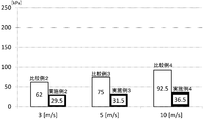
- FIG. 9 is a drawing-substituting graph showing the time required to stabilize the sheath flow in Examples 2 to 4 and Comparative Examples 2 to 4 in Experimental Example 3.
- FIG. 10 is a drawing-substituting graph showing the time required to stabilize the sheath flow in Examples 5 to 7 and Comparative Examples 5 to 7 in Experimental Example 3.
- Control device 1 (1) Pressurizing unit 11 (2) Pneumatic pressure measuring unit 12 (3) Water pressure measuring unit 13 (4) Control unit 14 2.
- Control system 10 (1) Pressurizing device 110 (2) Pneumatic pressure measuring device 120 (3) Water pressure measuring device 130 (4)
- Control device 140 3. Analysis device, particle sorting device (1) Flow path P (2) Light irradiation unit 111 (3) Photodetector 112 (4) Analysis unit 113 (5) Sorting unit 121 4).
- Control method (1) Pressurization process I (2) Air pressure measurement process II (3) Water pressure measurement process III (4) Control process IV 5. Analysis method, particle sorting method (1) Flow process V (2) Light irradiation process VI (3) Light detection step VII (4) Analysis step VIII (5) Preparative process IX 6). Analysis program (1) First control function (2) Second control function (3) Switching control function
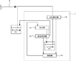
- FIG. 1 is a schematic conceptual diagram schematically showing the first embodiment of the control device 1 according to the present technology.
- the control device 1 according to the present technology is a control device that controls the flow velocity of a laminar flow, and roughly includes a pressurizing unit 11, an air pressure measuring unit 12, a water pressure measuring unit 13, and a control unit 14.
- a pressurizing unit 11 an air pressure measuring unit 12
- a water pressure measuring unit 13 a control unit 14.
- the flow path P is also illustrated for convenience, but the control apparatus 1 according to the present technology does not include the flow path P.
- Pressurizing unit 11 pressurization is performed on the fluid F that forms a laminar flow.
- the method of pressurization in the pressurization unit 11 is not particularly limited, and a known pressurization method can be freely selected and used.
- pressurization can be performed by sending compressed air into a container in which a fluid is stored using a compressed air generation source such as a compressor and an electropneumatic regulator.
- Pneumatic pressure measuring unit 12 In the air pressure measurement unit 12, the pressure applied to the fluid F by the pressurization unit 11 is measured.
- a known pressure gauge can be freely selected and used for the air measurement unit 12 of the control device 1 according to the present technology.
- Water pressure measuring unit 13 In the water pressure measurement unit 13, the water pressure of the fluid F pressurized by the pressure unit 11 is measured.
- a known water pressure gauge can be freely selected and used for the water pressure measuring unit 13 of the control device 1 according to the present technology.
- Control unit 14 In the control unit 14, the pressurization unit 11 applies the fluid F to the fluid F based on either the air pressure measured by the air pressure measurement unit 12 or the water pressure measured by the water pressure measurement unit 13. The pressure is controlled.
- control unit 14 performs control based on the air pressure measured by the air pressure measurement unit 12 (hereinafter, also simply referred to as “control based on air pressure”) and the water pressure measurement. Switching between control based on the water pressure measured by the unit 13 (hereinafter also simply referred to as “control based on water pressure”) is performed.
- control based on water pressure the water pressure measured by the unit 13
- the time required for the laminar flow velocity to stabilize can be shortened by appropriately switching between control based on air pressure and control based on water pressure, depending on the amount of fluid in the container and changes in temperature. More delicate control considering changes in water viscosity is possible.
- the order of switching in the control unit can be appropriately changed according to the purpose.
- the control based on the air pressure may be switched to the control based on the water pressure, or the control based on the water pressure may be switched to the control based on the air pressure.
- there is no limit to the number of switching operations such as switching from control based on air pressure to control based on water pressure, and then switching to control based on air pressure. It is possible to switch the number of times.
- control based on air pressure in the initial stage of laminar flow formation it is preferable to perform control based on air pressure in the initial stage of laminar flow formation, and then switch to control based on water pressure.
- control based on air pressure in the initial stage the time required for the laminar flow velocity to stabilize can be shortened, and then switching to control based on water pressure enables the amount of fluid in the container to be controlled. More delicate control considering water viscosity change due to temperature change is possible.
- the timing of switching from control based on air pressure to control based on water pressure is not particularly limited, and can be set as appropriate according to the situation. Particularly in the present technology, it is preferable to switch from control based on air pressure to control based on water pressure after the air pressure measured by the air pressure measurement unit 12 is stabilized. After the air pressure has stabilized, even if switching to control based on water pressure, the possibility of pressure overshoot is very low, so the time to stabilize the fluid at the desired water pressure can be shortened more effectively. Can do.
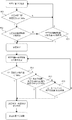
- FIG. 2 is a flowchart illustrating an example of the timing of switching from control based on air pressure to control based on water pressure in the control device 1 according to the present technology.
- the pressure applied to the fluid F is monitored by the air pressure measurement unit 12, and the control unit 14 starts control based on the air pressure.
- the stability of the air pressure monitored by the air pressure measurement unit 12 is determined.
- the method for determining the stability of the air pressure is not particularly limited. For example, when the measured air pressure falls within a certain range with respect to the target air pressure, and when a certain time has passed within the target air pressure range, the air pressure stability is stable. The method of judging that it was done is mentioned.
- FIG. 2 shows an example of determining that the target air pressure is stable when the target air pressure ⁇ 0.5 kPa continues for 5 seconds. More specifically, when the measured air pressure enters the target air pressure ⁇ 0.5 kPa (hereinafter also referred to as “stable air pressure region”) (see “P01” in FIG. 2), the air pressure stabilization duration time (See “P02” in FIG. 2), when 5 seconds have elapsed, the process proceeds to a determination of switching from control based on air pressure to control based on water pressure. If the stable air pressure range is not reached within 5 seconds, wait for a fixed time until the elapsed time in the stable air pressure region reaches 5 seconds (see “P03” in FIG. 2).
- the process proceeds to determination of switching from control based on air pressure to control based on water pressure. If the elapsed time in the stable air pressure region does not reach 5 seconds even after waiting for a certain time, control based on the air pressure is performed again, and the process returns to the air pressure stability determination in P01 until the air pressure is stabilized. You can continue.
- FIG. 2 shows an example in which switching is determined to be OK when the difference between the air pressure and the water pressure is less than 10 kPa.
- FIG. 2 illustrates an example in which switching is determined to be OK when the average deviation of the water pressure during 6400 ms is less than 0.3 kPa.
- FIG. 2 shows an example in which switching is forcibly performed when 90 seconds have elapsed since the air pressure was stabilized.
- the time required for the laminar flow velocity to be stabilized is shortened by appropriately performing stepwise determination and determination based on timeout.
- FIG. 3 is a schematic conceptual diagram schematically showing the second embodiment of the control device 1 according to the present technology.
- the second embodiment shown in FIG. 3 is a control device 1 according to the present technology for controlling the flow velocity of a sheath flow F2 in a laminar flow including a sample flow F1 including a sample and a sheath flow F2 surrounding the sample flow F1. It is an example using.
- the control device 1 can control any flow velocity of the sample flow F1 and the sheath flow F2, but is particularly preferably used for controlling the flow velocity of the sheath flow F2. Since the sample flow F1 is often smaller in amount than the sheath flow F2, and the flow rate of the sample flow F1 is relatively easy to control, a special control technique such as the control device 1 according to the present technology is used. This is because control is often possible without using.
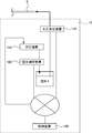
- FIG. 4 is a schematic conceptual diagram schematically showing the first embodiment of the control system 10 according to the present technology.
- the control system 10 according to the present technology is a control system that controls the flow velocity of a laminar flow.
- the control system 10 includes at least a pressurizing device 110, an air pressure measuring device 120, a water pressure measuring device 130, and a control device 140.
- the details of the pressurization device 110, the air pressure measurement device 120, the water pressure measurement device 130, and the control device 140 are the pressurization unit 11, the air pressure measurement unit 12, and the water pressure measurement unit 13 of the control device 1 according to the present technology described above. Since the control unit 14 and the control unit 14 are the same, the description thereof is omitted here.
- control system 10 In the control system 10 according to the present technology, some or all of the devices can be connected via a network.
- control device 1 and the control system 10 according to the present technology described above are suitably used as a control mechanism such as an analysis device that analyzes the particles S in the laminar flow and a particle sorting device that separates the particles S in the laminar flow. Can be used.
- FIG. 5 is a schematic conceptual diagram schematically showing the first embodiment of the analysis device according to the present technology
- FIG. 6 is a schematic concept schematically showing the first embodiment of the particle sorting device according to the present technology.
- a particle sorting apparatus in addition to the control device 1 according to the present technique described above, various types of apparatuses that are usually provided in a known analysis device, a particle sorting apparatus (a so-called flow cytometer, etc.) and the like.
- a function can be provided. Specifically, a light irradiation unit 111, a light detection unit 112, an analysis unit 113, a sorting unit 121, and the like can be provided.
- the flow path P can also be provided as needed.
- the flow channel P may be provided in advance in the analysis device and the particle sorting device according to the present technology, but a commercially available flow channel P or a disposable chip provided with the flow channel P may be used as the analysis device and the particle sorting device. It is also possible to install or analyze in the apparatus.
- the form of the flow path P that can be used in the analysis apparatus and the particle sorting apparatus according to the present technology is not particularly limited, and can be freely designed.
- the flow is not limited to the flow path P formed in the substrate T such as two-dimensional or three-dimensional plastic or glass as shown in the analysis device of FIG. 5, but as shown in the particle sorting device of FIG.
- the flow path P used in the cytometer can also be used for the analysis device and the particle sorting device according to the present technology.
- the channel width, the channel depth, and the channel cross-sectional shape of the channel P are not particularly limited as long as they can form a laminar flow, and can be freely designed.
- a micro flow channel having a flow channel width of 1 mm or less can also be used for the analysis device and the particle sorting device according to the present technology.
- a micro flow channel having a flow channel width of 10 ⁇ m or more and 1 mm or less can be suitably used by an analysis apparatus and a particle sorting apparatus according to the present technology.
- a light detection unit 112 described later can be disposed on the opposite side across a light irradiation unit 111 described later and the substrate T, and optical information from the bottom surface side of the flow path P can be detected. It is for doing so.
- Light irradiation unit 111 In the light irradiation unit 111, light irradiation is performed on the particles S flowing through the flow path P.
- the type of light emitted from the light irradiation unit 111 is not particularly limited, but in order to reliably generate fluorescence and scattered light from the particles S, light having a constant light direction, wavelength, and light intensity is desirable.
- a laser, LED, etc. can be mentioned.
- the type of the laser is not particularly limited, and an argon ion (Ar) laser, a helium-neon (He-Ne) laser, a die (dye) laser, a krypton (Cr) laser, a semiconductor laser, or a semiconductor laser
- argon ion (Ar) laser argon ion (Ar) laser
- He-Ne helium-neon
- He-Ne helium-neon
- Cr krypton
- semiconductor laser or a semiconductor laser
- One or two or more solid lasers combined with wavelength conversion optical elements can be used in any combination.
- Photodetector 112 In the light detection unit 112, optical information emitted from the particles S is detected by light irradiation by the light irradiation unit 111.
- the type of the light detection unit 112 that can be used in the present technology is not particularly limited as long as optical information can be detected, and a known light detector can be freely selected and employed.
- a known light detector can be freely selected and employed.
- fluorescence measuring instrument scattered light measuring instrument, transmitted light measuring instrument, reflected light measuring instrument, diffracted light measuring instrument, ultraviolet spectroscopic measuring instrument, infrared spectroscopic measuring instrument, Raman spectroscopic measuring instrument, FRET measuring instrument, FISH measuring instrument and others
- spectrum measuring devices so-called multi-channel photodetectors in which a plurality of photodetectors are arranged in an array, and the like can be used alone or in combination of two or more.
- the installation location of the light detection unit 112 in the analysis device and the particle sorting device according to the present technology is not particularly limited as long as the optical information emitted from the particles S can be detected, and can be freely designed.
- Analysis unit 113 In the analysis unit 113, the particle S is analyzed based on the optical information emitted from the particle S detected by the light detection unit 112.
- the analysis unit 113 is not essential in the analysis device and the particle sorting device according to the present technology, and based on the optical information detected by the light detection unit 112, the state of the particles S using an external analysis device or the like. Etc. can also be analyzed.
- Sorting unit 121 In the sorting unit 121, the particles S are sorted based on the optical information detected by the light detecting unit 112 or the analysis result of the particles S analyzed by the analyzing unit 113. For example, the sorting unit 121 can sort the particles S downstream of the flow path P based on the analysis results of the size, shape, internal structure, and the like of the particles S analyzed from the optical information. .
- a vibration element 121a that vibrates at a predetermined frequency is used to apply vibration to the whole or a part of the flow path P, thereby discharging the flow path P. Droplets are generated from the outlet.
- the vibration element 121a to be used is not particularly limited, and a known element can be freely selected and used. As an example, a piezoelectric vibration element or the like can be given.
- the size of the droplet can be adjusted to generate a droplet containing a certain amount of the sample. it can.
- the generated droplet is charged with a positive or negative charge based on the analysis result of the size, form, internal structure, etc. of the analyzed particle S (see reference numeral 121b in FIG. 6). Then, the charged droplets are sorted by changing the path in a desired direction by the counter electrode 121c to which a voltage is applied.
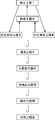
- FIG. 7 is a flowchart of the control method according to the present technology.
- the control method according to the present technology is a control method for controlling the flow velocity of the laminar flow, and is roughly a method of performing at least the pressurization step I, the air pressure measurement step II, the water pressure measurement step III, and the control step IV. .
- the details of the pressurization process I, the air pressure measurement process II, the water pressure measurement process III, and the control process IV are as follows. Since the control unit 14 is the same as the respective method, the description is omitted here.
- the control method according to the present technology described above can be suitably used as an analysis method for analyzing particles S in a laminar flow and a laminar flow control method in a particle sorting method for sorting particles S in a laminar flow. it can.
- FIG. 8 is a flowchart of the analysis method according to the present technology
- FIG. 9 is a flowchart of the particle sorting method according to the present technology.
- the pressurization step I, air pressure measurement step II, water pressure measurement step III, and control step IV used in the analysis method shown in FIG. 8 and the particle sorting method shown in FIG. 9 are as described above. Omit.
- the flow process V is a process of allowing the particles S to flow in the laminar flow.
- the flow method of the particles S into the laminar flow is not particularly limited.
- the sample flow F1 containing the particles S is sandwiched between the fluid medium that promotes rectification (sheath flow F2).
- the method of conveying is mentioned. If transported in this way, a laminar flow of the sample flow F1 containing the particles S can be formed, which is more preferable.
- the type of the fluid medium is not particularly limited as long as it has a function to promote rectification of the sample flow F1 including the particles S. For example, when the particles S are cells, physiological saline or the like Can be used.
- the particles S are preferably modified with a fluorescent substance such as a fluorescent dye, a radioactive substance, an intercalator, or a labeling substance such as microbeads so that optical information can be detected in the light detection step VII.
- a fluorescent dye such as a fluorescent dye, a radioactive substance, an intercalator, or a labeling substance such as microbeads
- the type thereof is not particularly limited, and any known fluorescent dye can be used.
- Cascade Blue Fluorescein isothiocyanate (FITC), Phycoerythrin (PE), Propidium iodide (PI), Texas red (TR), Peridininchlorophyll protein (PerCP), Allophycocyanin (APC), 4 ', 6-Diamidino-2 -phenylindole (DAPI), Cy3, Cy5, Cy7, etc.
- FITC Fluorescein isothiocyanate
- PE Phycoerythrin
- PI Propidium iodide
- TR Texas red
- the particle S itself emits light like a fluorescent protein, it is not necessary to modify with a labeling substance. Also, when a substance that can change the fluorescent color of the substance by using the substance S in the flow path P to change the fluorescent color of the substance as in the principle of FRET is used as the particle S. S need not be modified.
- An analysis program is a laminar flow control program used for controlling the flow velocity of a laminar flow, and is a program for causing a computer to realize a first control function, a second control function, and a switching control function. .
- a laminar flow control program used for controlling the flow velocity of a laminar flow
- a switching control function a program for causing a computer to realize a first control function, a second control function, and a switching control function.
- a 1st control function is a function which controls the applied pressure to the said fluid based on the pneumatic pressure added to the fluid which forms the said laminar flow.
- the second control function is a function for controlling the pressure applied to the fluid based on the water pressure of the fluid forming the laminar flow.
- the switching control function is a function for switching between the realization of the first control function and the realization of the second control function. Since the details of the switching control function are the same as the switching between the control based on the air pressure and the control based on the water pressure performed by the control unit 14 of the control device 1 described above, the description thereof is omitted here.
- Example demonstrated below shows an example of the typical Example of this invention, and, thereby, the range of this invention is not interpreted narrowly.
- FIG. 10 is a schematic conceptual diagram schematically showing the apparatus used in Experimental Examples 1 to 3.
- the symbol a is a compressor which is a compressed air generation source.
- the air tube b connected to the compressor a branches into a sheath liquid pressure adjusting regulator c and a sample liquid pressure adjusting regulator d.
- the sheath liquid pressure adjusting regulator c is connected to a sheath liquid container f (capacity 10 L) that stores the sheath liquid via an air pressure sensor e that measures the pressure applied to the sheath liquid.
- the sample liquid pressure adjusting regulator d is connected to the sample liquid container h via an air pressure sensor g for measuring the pressure applied to the sample liquid.
- the sheath nozzle i immersed in the sheath liquid of the sheath liquid container f is guided into the chip flow cell m via a water pressure sensor (liquid pressure gauge) j and sheath liquid inflow control valves k and l.
- the sample tube o connected to the sample nozzle n immersed in the sample liquid in the sample liquid container h is led into the chip flow cell m through the sample liquid inflow valve p.
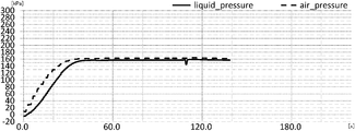
- FIG. 11 shows fluctuations in air pressure and water pressure in Reference Example 1
- FIG. 12 shows fluctuations in air pressure and water pressure in Reference Example 2.
- FIG. 11 when the amount of sheath liquid in the sheath liquid container f was almost full, the flow rate was stabilized in about 60 seconds.
- FIG. 12 when the amount of sheath liquid in the sheath liquid container f is small, it has been found that there is a time lag between the increase in air pressure and the increase in water pressure. Moreover, overshoot occurred in both air pressure and water pressure, and it took 180 seconds or more to stabilize the flow velocity.
- Example 2 In Experimental Example 2, the sheath flow is controlled by controlling the pressure applied to the sheath liquid based only on the water pressure of the sheath flow, and when switching from the control based on the air pressure to the control based on the water pressure. The difference in time required for the flow rate to stabilize was examined.
- control is started based on the output of the air pressure sensor e from the non-pressurized state ( ⁇ 8 kPa to ⁇ 5 kPa), and when the differential pressure between the air pressure and the water pressure becomes less than 10 kPa, Switching to control based on the output of the water pressure sensor j was performed, and control was performed until the flow velocity of the sheath flow was stabilized at 10 m / s (water pressure of about 158.0 kPa). During the control, the air pressure and water pressure were monitored by the air pressure sensor e and the water pressure sensor j.
- FIG. 13 shows fluctuations in air pressure, water pressure, and the differential pressure between air pressure and water pressure in Example 1
- FIG. 14 shows fluctuations in air pressure, water pressure, and the differential pressure between air pressure and water pressure in Comparative Example 1.
- a time lag occurs between the increase in the air pressure and the increase in the water pressure, as in Reference Example 2, and both the air pressure and the water pressure are overshot. It took 180 seconds or more to stabilize the flow rate.
- the air pressure and the water pressure are increased even when the amount of sheath liquid in the sheath liquid container f is small. In both cases, overshoot did not occur and the flow rate stabilized in about 120 seconds.
- Example 3 In Experimental Example 3, when the amount of sheath liquid in the sheath liquid container f is almost full, and when the target flow velocity of the sheath flow is different, the sheath flow is based only on the water pressure of the sheath flow as in Example 2.
- control is started based on the output of the air pressure sensor e from the non-pressurized state ( ⁇ 8 kPa to ⁇ 5 kPa), and when the differential pressure between the air pressure and the water pressure becomes less than 10 kPa, Switching to control based on the output of the water pressure sensor j was performed, and control was performed until the flow velocity of the sheath flow was stabilized at 3 m / s (water pressure of about 33.0 kPa). During the control, the air pressure and water pressure were monitored by the air pressure sensor e and the water pressure sensor j.
- Example 3 Control was performed in the same manner as in Example 2 except that the control was performed until the flow velocity of the sheath flow was stabilized at 5 m / s (water pressure of about 62.0 kPa).
- Example 4 Control was performed in the same manner as in Example 2 except that the control was performed until the flow velocity of the sheath flow was stabilized at 10 m / s (water pressure of about 150.0 kPa).
- Example 5 Control was performed in the same manner as in Example 2 except that 2.7 kg of sheath liquid was placed in the sheath liquid container f of the apparatus.
- Example 6 Control was performed in the same manner as in Example 3 except that 2.7 kg of sheath liquid was placed in the sheath liquid container f of the apparatus.
- Example 7 Control was performed in the same manner as in Example 4 except that 2.7 kg of sheath liquid was placed in the sheath liquid container f of the apparatus.
- Control apparatus 11 Pressurization part 12 Air pressure measurement part 13 Water pressure measurement part 14 Control part 10
- Control system 110 Pressurization apparatus 120 Air pressure measurement apparatus 130 Water pressure measurement apparatus 140
- Control apparatus P Channel 111 Light irradiation part 112 Light detection part 113 Analysis part 121 Preparatory part I Pressurization process II Air pressure measurement process III Water pressure measurement process IV Control process V Flow process VI Light irradiation process VII Light detection process VIII Analysis process IX Preparative process
Landscapes
- Chemical & Material Sciences (AREA)
- General Physics & Mathematics (AREA)
- Physics & Mathematics (AREA)
- Biochemistry (AREA)
- Life Sciences & Earth Sciences (AREA)
- Analytical Chemistry (AREA)
- Health & Medical Sciences (AREA)
- General Health & Medical Sciences (AREA)
- Dispersion Chemistry (AREA)
- Immunology (AREA)
- Pathology (AREA)
- Engineering & Computer Science (AREA)
- Automation & Control Theory (AREA)
- Sampling And Sample Adjustment (AREA)
- Flow Control (AREA)
Abstract
Description
水流系では、分析対象となる微小粒子をフローセル(流路)中で一列に整列させる。より具体的には、シース流を一定の流速でフローセル内に流入させ、その状態で微小粒子を含むサンプル流をフローセル中央部にゆっくりと注入する。この時、laminar flowの原理によりそれぞれの流れは互いに混合されず、層を成した流れ(層流)が形成される。そして、分析対象となる微小粒子の大きさ等に応じて、シース流とサンプル流の流入量を調節し、微小粒子を一つ一つが整列した状態で通流させる。
光学系では、分析対象となる微小粒子にレーザーなどの光を照射し、微小粒子から発せられる蛍光や散乱光を検出する。微小粒子を、前記水流系(1)において、一つ一つが整列した状態でレーザー照射部を通流させ、一つ一つの微小粒子が通過する毎に、微小粒子から発せられる蛍光や散乱光を、パラメータ毎に光学検出器を用いて検出し、微小粒子一つ一つの特性を分析する。
電気・解析系では、光学系において検出した光学的情報を、電気的信号(電圧パルス)に変換する。変換された電気的信号はアナログ-デジタル変換され、このデータをもとに解析用コンピューターとソフトウェアでヒストグラムを抽出し、解析を行う。
分取系では、測定を終えた微小粒子を分離し、回収する。代表的な分取方法としては、測定を終えた微小粒子にプラス又はマイナスの電荷を加え、フローセルを、電位差を有する2つの偏向板で挟み込み、帯電された微小粒子はその電荷に応じていずれかの偏向板に引き寄せられることにより、分取する方法がある。
前記層流を形成する流体を加圧する加圧部と、
該加圧部によって前記流体に付加される圧力を測定する空圧測定部と、
前記加圧部によって加圧された前記流体の水圧を測定する水圧測定部と、
前記空圧測定部によって測定された空圧若しくは前記水圧測定部によって測定された水圧のいずれか一方に基づいて、前記加圧部による前記流体への加圧力を制御する制御部と、を備え、
前記制御部は、前記空圧測定部によって測定された空圧に基づく制御と、前記水圧測定部によって測定された水圧に基づく制御と、の切り替えを行う、制御装置を提供する。
本技術に係る制御装置において、前記制御部における切り替えの順番は、目的に応じて適宜変更することが可能であるが、例えば、前記制御部では、前記空圧測定部によって測定された空圧に基づく制御から、前記水圧測定部によって測定された水圧に基づく制御への切り替えを行うことができる。
この場合、前記制御部における切り替えの時期は特に限定されないが、前記空圧測定部によって測定された空圧が安定した以降に、前記空圧測定部によって測定された空圧に基づく制御から、前記水圧測定部によって測定された水圧に基づく制御への切り替えを行うことができる。
また、より具体的には、例えば、前記制御部では、下記の(a)から(c)から選択される一以上の時点において、前記空圧測定部によって測定された空圧に基づく制御から、前記水圧測定部によって測定された水圧に基づく制御への切り替えを行うことができる。
(a)前記空圧測定部によって測定された空圧と、前記水圧測定部によって測定された水圧と、の差圧が、所定値以下となった時点。
(b)前記水圧測定部によって測定された水圧の変動が、所定値以下となった時点。
(c)前記空圧測定部によって測定された空圧に基づく制御時間が、所定時間を超えた時点。
本技術に係る制御装置が制御可能な層流も特に限定されないが、例えば、前記層流が、サンプルを含むサンプル流と、該サンプル流を囲むシース流と、からなり、
前記流体は、前記シース流を形成するシース液とすることができる。
前記制御部では、下記の(1)から(3)の順番で、前記空圧測定部によって測定された空圧に基づく制御から、前記水圧測定部によって測定された水圧に基づく制御への切り替えの判定を行うこともできる。
(1)前記空圧測定部によって測定された空圧と、前記水圧測定部によって測定された水圧と、の差圧が、所定値以下になったかの判定。
(2)前記水圧測定部によって測定された水圧の変動が、所定値以下になったかの判定。
(3)前記空圧測定部によって測定された空圧に基づく制御時間が、所定時間を超えたかの判定。
前記層流を形成する流体を加圧する加圧装置と、
該加圧装置によって前記流体に付加される圧力を測定する空圧測定装置と、
前記加圧装置によって加圧された前記流体の水圧を測定する水圧測定装置と、
前記空圧測定装置によって測定された空圧若しくは前記水圧測定装置によって測定された水圧のいずれか一方に基づいて、前記加圧装置による前記流体への加圧力を制御する制御装置と、を備え、
前記制御装置は、前記空圧測定装置によって測定された空圧に基づく制御と、前記水圧測定装置によって測定された水圧に基づく制御と、の切り替えを行う、制御システムを提供する。
本技術に係る制御システムでは、各装置間の少なくとも一部を、ネットワークを介して接続することができる。
前記シース流を形成するシース液を加圧する加圧部と、
該加圧部によって前記シース液に付加される圧力を測定する空圧測定部と、
前記加圧部によって加圧された前記シース液の水圧を測定する水圧測定部と、
前記空圧測定部によって測定された空圧若しくは前記水圧測定部によって測定された水圧のいずれか一方に基づいて、前記加圧部による前記シース液への加圧力を制御する制御部と、を備え、
前記制御部は、前記空圧測定部によって測定された空圧に基づく制御と、前記水圧測定部によって測定された水圧に基づく制御と、の切り替えを行う、解析装置を提供する。
また、本技術では、粒子を含むサンプル流と、該サンプル流を囲むシース流と、からなる層流中の前記粒子を分取する粒子分取装置であって、
前記シース流を形成するシース液を加圧する加圧部と、
該加圧部によって前記シース液に付加される圧力を測定する空圧測定部と、
前記加圧部によって加圧された前記シース液の水圧を測定する水圧測定部と、
前記空圧測定部によって測定された空圧若しくは前記水圧測定部によって測定された水圧のいずれか一方に基づいて、前記加圧部による前記シース液への加圧力を制御する制御部と、を備え、
前記制御部は、前記空圧測定部によって測定された空圧に基づく制御と、前記水圧測定部によって測定された水圧に基づく制御と、の切り替えを行う、粒子分取装置を提供する。
前記層流を形成する流体を加圧する加圧工程と、
該加圧工程において前記流体に付加される圧力を測定する空圧測定工程と、
前記加圧工程において加圧された前記流体の水圧を測定する水圧測定工程と、
前記空圧測定工程において測定された空圧若しくは前記水圧測定工程において測定された水圧のいずれか一方に基づいて、前記加圧工程における前記流体への加圧力を制御する制御工程と、を行い、
前記制御工程では、前記空圧測定工程において測定された空圧に基づく制御と、前記水圧測定工程において測定された水圧に基づく制御と、の切り替えが行われる、制御方法を提供する。
前記層流を形成する流体に付加される空圧に基づいて、前記流体への加圧力を制御する第1制御機能と、
前記層流を形成する流体の水圧に基づいて、前記流体への加圧力を制御する第2制御機能と、
前記第1制御機能の実現と、前記第2制御機能の実現と、の切り替えを行う切り替え制御機能と、
をコンピューターに実現させるための層流制御プログラムを提供する。
なお、ここに記載された効果は、必ずしも限定されるものではなく、本技術中に記載されたいずれかの効果であってもよい。
1.制御装置1
(1)加圧部11
(2)空圧測定部12
(3)水圧測定部13
(4)制御部14
2.制御システム10
(1)加圧装置110
(2)空圧測定装置120
(3)水圧測定装置130
(4)制御装置140
3.解析装置、粒子分取装置
(1)流路P
(2)光照射部111
(3)光検出部112
(4)解析部113
(5)分取部121
4.制御方法
(1)加圧工程I
(2)空圧測定工程II
(3)水圧測定工程III
(4)制御工程IV
5.解析方法、粒子分取方法
(1)通流工程V
(2)光照射工程VI
(3)光検出工程VII
(4)解析工程VIII
(5)分取工程IX
6.解析ブログラム
(1)第1制御機能
(2)第2制御機能
(3)切り替え制御機能
図1は、本技術に係る制御装置1の第1実施形態を模式的に示す模式概念図である。本技術に係る制御装置1は、層流の流速を制御する制御装置であって、大別すると、加圧部11、空圧測定部12、水圧測定部13、制御部14を少なくとも備える。以下、各部について、詳細に説明する。なお、図1及び後述する図3及び図4では、流路Pについても、便宜上、図示しているが、本技術に係る制御装置1には流路Pは含まれない。
加圧部11では、層流を形成する流体Fへの加圧が行われる。加圧部11における加圧の方法は特に限定されず、公知の加圧方法を自由に選択して用いることができる。例えば、コンプレッサなどの圧縮空気発生源と電空調整機などを用いて、流体が貯蔵されている容器内に圧縮空気を送り込むなどして、加圧を行うことができる。
空圧測定部12では、前記加圧部11によって前記流体Fに付加される圧力の測定が行われる。本技術に係る制御装置1の空気測定部12には、公知の圧力計を自由に選択して用いることができる。
水圧測定部13では、前記加圧部11によって加圧された前記流体Fの水圧の測定が行われる。本技術に係る制御装置1の水圧測定部13には、公知の水圧計を自由に選択して用いることができる。
制御部14では、前記空圧測定部12によって測定された空圧、若しくは、前記水圧測定部13によって測定された水圧、のいずれか一方に基づいて、前記加圧部11による前記流体Fへの加圧力の制御が行われる。
図4は、本技術に係る制御システム10の第1実施形態を模式的に示す模式概念図である。本技術に係る制御システム10は、層流の流速を制御する制御システムであって大別すると、加圧装置110、空圧測定装置120、水圧測定装置130、制御装置140を少なくとも備える。なお、加圧装置110、空圧測定装置120、水圧測定装置130、制御装置140の詳細は、前述した本技術に係る制御装置1の加圧部11、空圧測定部12、水圧測定部13、制御部14と、それぞれ同一であるため、ここでは説明を省略する。
前述した本技術に係る制御装置1及び制御システム10は、層流中の粒子Sを解析する解析装置や、層流中の粒子Sを分取する粒子分取装置などの制御機構として、好適に用いることができる。
流路Pは、本技術に係る解析装置及び粒子分取装置に予め備えていてもよいが、市販の流路Pや流路Pが設けられた使い捨てのチップなどを、解析装置及び粒子分取装置に設置して解析又は分取を行うことも可能である。
光照射部111では、流路Pを通流中の粒子Sに対して光の照射が行われる。
光検出部112では、光照射部111による光照射によって、粒子Sから発せられた光学的情報の検出が行われる。
解析部113では、前記光検出部112によって検出された粒子Sから発せられた光学的情報に基づいて、粒子Sの解析が行われる。この解析部113は、本技術に係る解析装置及び粒子分取装置では必須ではなく、前記光検出部112によって検出された光学的情報に基づいて、外部の解析装置等を用いて粒子Sの状態等を解析することも可能である。
分取部121では、前記光検出部112により検出された前記光学的情報、又は、前記解析部113で解析された粒子Sの解析結果に基づいて、粒子Sの分取が行われる。例えば、分取部121では、光学的情報から解析された粒子Sの大きさ、形態、内部構造等の解析結果に基づいて、流路Pの下流において、粒子Sの分取を行うことができる。
図7は、本技術に係る制御方法のフロー図である。本技術に係る制御方法は、層流の流速を制御する制御方法であって、大別すると、加圧工程I、空圧測定工程II、水圧測定工程III、制御工程IVを少なくとも行う方法である。なお、加圧工程I、空圧測定工程II、水圧測定工程III、制御工程IVの詳細は、前述した本技術に係る制御装置1の加圧部11、空圧測定部12、水圧測定部13、制御部14が、それぞれ行う方法と同一であるため、ここでは説明を省略する。
前述した本技術に係る制御方法は、層流中の粒子Sを解析する解析方法や、層流中の粒子Sを分取する粒子分取方法における層流の制御方法として、好適に用いることができる。
通流工程Vは、層流中に粒子Sを通流させる工程である。
本技術に係る解析プログラムは、層流の流速の制御に用いられる層流制御プログラムであって、第1制御機能、第2制御機能、及び切り替え制御機能を、コンピューターに実現させるためのプログラムである。以下、各機能について、詳細に説明する。
第1制御機能は、前記層流を形成する流体に付加される空圧に基づいて、前記流体への加圧力を制御する機能である。
第2制御機能は、前記層流を形成する流体の水圧に基づいて、前記流体への加圧力を制御する機能である。
切り替え制御機能は、前記第1制御機能の実現と、前記第2制御機能の実現と、の切り替えを行う機能である。切り替え制御機能の詳細は、前述した制御装置1の制御部14が行う空圧に基づく制御と水圧に基づく制御との切り替えと同一であるため、ここでは説明を省略する。
実験例1では、シース流の水圧のみに基づいて、シース液への加圧力の制御を行った場合に、シース残量の違いによるシース流の流速が安定するまでに要する時間の違いについて検討した。
図10は、実験例1~3で用いた装置を模式的に示す模式概念図である。図10中、符号aは圧縮空気発生源であるコンプレッサである。このコンプレッサaに接続されたエアチューブbは、シース液の圧力調整用レギュレータcと、サンプル液圧力調整用レギュレータdに分岐する。シース液圧力調整用レギュレータcは、シース液に加圧される圧を計測する空圧センサeを介してシース液を蓄えるシース液容器f(容量10L)に接続されている。また、サンプル液圧力調整用レギュレータdは、サンプル液に加圧される圧を計測する空圧センサgを介してサンプル液容器hに接続されている。シース液容器fのシース液中に浸潰されたシースノズルiは、水圧センサ(液体圧力計)j、シース液流入制御弁k、lを介してチップフローセルm内に導かれている。また、サンプル液容器hのサンプル液中に浸潰されたサンプルノズルnに接続されたサンプルチューブoは、サンプル液流入弁pを介してチップフローセルm内に導かれている。
<参考例1>
前記装置のシース液容器fに、シース液を10.9kg入れた状態で、水圧センサjの出力のみに基づいて、シース液に加圧される圧を調整することで、シース液の流速をフィードバック制御した。より具体的には、無加圧(-8kPa~-5kPa)の状態から制御を開始し、シース流の流速が10m/s(水圧158.0kPa程度)に安定するまで、制御を行った。制御中、空圧センサeと水圧センサjにて、空圧及び水圧のモニタリングを行った。
シース液容器fに、シース液を2.5kg入れた以外は、実験例1と同一の方法で、制御を行った。
参考例1における空圧及び水圧の変動を図11に、参考例2における空圧及び水圧の変動を図12に、それぞれ示す。図11に示す通り、シース液容器f内のシース液量がほぼ満量である場合には、60秒程度で流速が安定した。一方、図12に示す通り、シース液容器f内のシース液量が少ない場合には、空圧の上昇と水圧の上昇に、タイムラグが生じることが分かった。また、空圧及び水圧共に、オーバーシュートが発生し、流速の安定までに、180秒以上の時間を要した。
実験例2では、シース流の水圧のみに基づいてシース液への加圧力の制御を行った場合と、空圧に基づく制御から水圧に基づく制御への切り替えを行った場合とで、シース流の流速が安定するまでに要する時間の違いについて検討した。
<実施例1>
前記装置のシース液容器fに、シース液を2.5kg入れた状態で、空圧センサeの出力に基づいて、シース液に加圧される圧を調整することで、シース液の流速をフィードバック制御した後に、水圧センサjの出力に基づいて、シース液に加圧される圧を調整することで、シース液の流速をフィードバック制御した。より具体的には、無加圧(-8kPa~-5kPa)の状態から、空圧センサeの出力に基づいて制御を開始し、空圧と水圧の差圧が10kPa未満となった時点で、水圧センサjの出力に基づく制御への切り替えを行い、シース流の流速が10m/s(水圧158.0kPa程度)に安定するまで、制御を行った。制御中、空圧センサeと水圧センサjにて、空圧及び水圧のモニタリングを行った。
前記実施例1の前記参考例2と同一の方法で、制御を行った。
実施例1における空圧、水圧及び空圧と水圧との差圧の変動を図13に、比較例1における空圧、水圧及び空圧と水圧との差圧の変動を図14に、それぞれ示す。図14に示す通り、水圧のみに基づいた制御を行った比較例1は、前記参考例2と同様に、空圧の上昇と水圧の上昇に、タイムラグが生じ、空圧及び水圧共に、オーバーシュートが発生し、流速の安定までに、180秒以上の時間を要した。一方、図13に示す通り、空圧に基づく制御から水圧に基づく制御への切り替えを行った実施例1では、シース液容器f内のシース液量が少ない場合であっても、空圧及び水圧共に、オーバーシュートは発生せず、120秒程度で流速が安定した。
実験例3では、シース液容器f内のシース液量がほぼ満量である場合、及び、シース流の目標流速が異なる場合に、実施例2と同様に、シース流の水圧のみに基づいてシース液への加圧力の制御を行った場合と、空圧に基づく制御から水圧に基づく制御への切り替えを行った場合とで、シース流の流速が安定するまでに要する時間の違いについて検討した。
<実施例2>
前記装置のシース液容器fに、シース液を10.9kg入れた状態で、空圧センサeの出力に基づいて、シース液に加圧される圧を調整することで、シース液の流速をフィードバック制御した後に、水圧センサjの出力に基づいて、シース液に加圧される圧を調整することで、シース液の流速をフィードバック制御した。より具体的には、無加圧(-8kPa~-5kPa)の状態から、空圧センサeの出力に基づいて制御を開始し、空圧と水圧の差圧が10kPa未満となった時点で、水圧センサjの出力に基づく制御への切り替えを行い、シース流の流速が3m/s(水圧33.0kPa程度)に安定するまで、制御を行った。制御中、空圧センサeと水圧センサjにて、空圧及び水圧のモニタリングを行った。
シース流の流速が5m/s(水圧62.0kPa程度)に安定するまで、制御を行った以外は、実施例2と同様の方法にて制御を行った。
シース流の流速が10m/s(水圧150.0kPa程度)に安定するまで、制御を行った以外は、実施例2と同様の方法にて制御を行った。
前記装置のシース液容器fに、シース液を2.7kg入れた以外は、実施例2と同様の方法にて制御を行った。
前記装置のシース液容器fに、シース液を2.7kg入れた以外は、実施例3と同様の方法にて制御を行った。
前記装置のシース液容器fに、シース液を2.7kg入れた以外は、実施例4と同様の方法にて制御を行った。
前記装置のシース液容器fに、シース液を10.9kg入れた状態で、水圧センサjの出力のみに基づいて、シース液に加圧される圧を調整することで、シース液の流速をフィードバック制御した。より具体的には、無加圧(-8kPa~-5kPa)の状態から制御を開始し、シース流の流速が3m/s(水圧33.0kPa程度)に安定するまで、制御を行った。制御中、空圧センサeと水圧センサjにて、空圧及び水圧のモニタリングを行った。
シース流の流速が5m/s(水圧62.0kPa程度)に安定するまで、制御を行った以外は、比較例2と同様の方法にて制御を行った。
シース流の流速が10m/s(水圧150.0kPa程度)に安定するまで、制御を行った以外は、比較例2と同様の方法にて制御を行った。
前記装置のシース液容器fに、シース液を2.7kg入れた以外は、比較例2と同様の方法にて制御を行った。
前記装置のシース液容器fに、シース液を2.7kg入れた以外は、比較例3と同様の方法にて制御を行った。
前記装置のシース液容器fに、シース液を2.7kg入れた以外は、比較例4と同様の方法にて制御を行った。
実施例2~4及び比較例2~4のシース流安定までに要した時間を図15に、実施例5~7及び比較例5~7のシース流安定までに要した時間を図16に、それぞれ示す。図15に示す通り、シース液容器f内のシース液量がほぼ満量である場合であっても、シース流の水圧のみに基づいてシース液への加圧力の制御を行った比較例2~4に比べ、空圧に基づく制御から水圧に基づく制御への切り替えを行った実施例2~4の方が、シース流の流速が安定するまでに要する時間が、全て1/2以下に短縮されることが証明された。特に、安定流速を10m/sに設定した比較例4と実施例4とでは、流速安定までに要する時間が2.53倍も短縮化されることが分かった。
11 加圧部
12 空圧測定部
13 水圧測定部
14 制御部
10 制御システム
110 加圧装置
120 空圧測定装置
130 水圧測定装置
140 制御装置
P 流路
111 光照射部
112 光検出部
113 解析部
121 分取部
I 加圧工程
II 空圧測定工程
III 水圧測定工程
IV 制御工程
V 通流工程
VI 光照射工程
VII 光検出工程
VIII 解析工程
IX 分取工程
Claims (12)
- 層流の流速を制御する制御装置であって、
前記層流を形成する流体を加圧する加圧部と、
該加圧部によって前記流体に付加される圧力を測定する空圧測定部と、
前記加圧部によって加圧された前記流体の水圧を測定する水圧測定部と、
前記空圧測定部によって測定された空圧若しくは前記水圧測定部によって測定された水圧のいずれか一方に基づいて、前記加圧部による前記流体への加圧力を制御する制御部と、を備え、
前記制御部は、前記空圧測定部によって測定された空圧に基づく制御と、前記水圧測定部によって測定された水圧に基づく制御と、の切り替えを行う、制御装置。 - 前記制御部では、前記空圧測定部によって測定された空圧に基づく制御から、前記水圧測定部によって測定された水圧に基づく制御への切り替えが行われる請求項1記載の制御装置。
- 前記制御部では、前記空圧測定部によって測定された空圧が安定した以降に、前記空圧測定部によって測定された空圧に基づく制御から、前記水圧測定部によって測定された水圧に基づく制御への切り替えが行われる請求項2記載の制御装置。
- 前記制御部では、下記の(a)から(c)から選択される一以上の時点において、前記空圧測定部によって測定された空圧に基づく制御から、前記水圧測定部によって測定された水圧に基づく制御への切り替えが行われる請求項2記載の制御装置。
(a)前記空圧測定部によって測定された空圧と、前記水圧測定部によって測定された水圧と、の差圧が、所定値以下となった時点。
(b)前記水圧測定部によって測定された水圧の変動が、所定値以下となった時点。
(c)前記空圧測定部によって測定された空圧に基づく制御時間が、所定時間を超えた時点。 - 前記層流は、サンプルを含むサンプル流と、該サンプル流を囲むシース流と、からなり、
前記流体は、前記シース流を形成するシース液である請求項1記載の制御装置。 - 前記制御部では、下記の(1)から(3)の順番で、前記空圧測定部によって測定された空圧に基づく制御から、前記水圧測定部によって測定された水圧に基づく制御への切り替えの判定が行われる請求項4記載の制御装置。
(1)前記空圧測定部によって測定された空圧と、前記水圧測定部によって測定された水圧と、の差圧が、所定値以下になったかの判定。
(2)前記水圧測定部によって測定された水圧の変動が、所定値以下になったかの判定。
(3)前記空圧測定部によって測定された空圧に基づく制御時間が、所定時間を超えたかの判定。 - 層流の流速を制御する制御システムであって、
前記層流を形成する流体を加圧する加圧装置と、
該加圧装置によって前記流体に付加される圧力を測定する空圧測定装置と、
前記加圧装置によって加圧された前記流体の水圧を測定する水圧測定装置と、
前記空圧測定装置によって測定された空圧若しくは前記水圧測定装置によって測定された水圧のいずれか一方に基づいて、前記加圧装置による前記流体への加圧力を制御する制御装置と、を備え、
前記制御装置は、前記空圧測定装置によって測定された空圧に基づく制御と、前記水圧測定装置によって測定された水圧に基づく制御と、の切り替えを行う、制御システム。 - 各装置間の少なくとも一部が、ネットワークを介して接続されている請求項7記載の制御システム。
- 粒子を含むサンプル流と、該サンプル流を囲むシース流と、からなる層流中の前記粒子を解析する解析装置であって、
前記シース流を形成するシース液を加圧する加圧部と、
該加圧部によって前記シース液に付加される圧力を測定する空圧測定部と、
前記加圧部によって加圧された前記シース液の水圧を測定する水圧測定部と、
前記空圧測定部によって測定された空圧若しくは前記水圧測定部によって測定された水圧のいずれか一方に基づいて、前記加圧部による前記シース液への加圧力を制御する制御部と、を備え、
前記制御部は、前記空圧測定部によって測定された空圧に基づく制御と、前記水圧測定部によって測定された水圧に基づく制御と、の切り替えを行う、解析装置。 - 粒子を含むサンプル流と、該サンプル流を囲むシース流と、からなる層流中の前記粒子を分取する粒子分取装置であって、
前記シース流を形成するシース液を加圧する加圧部と、
該加圧部によって前記シース液に付加される圧力を測定する空圧測定部と、
前記加圧部によって加圧された前記シース液の水圧を測定する水圧測定部と、
前記空圧測定部によって測定された空圧若しくは前記水圧測定部によって測定された水圧のいずれか一方に基づいて、前記加圧部による前記シース液への加圧力を制御する制御部と、を備え、
前記制御部は、前記空圧測定部によって測定された空圧に基づく制御と、前記水圧測定部によって測定された水圧に基づく制御と、の切り替えを行う、粒子分取装置。 - 層流の流速を制御する層流制御方法であって、
前記層流を形成する流体を加圧する加圧工程と、
該加圧工程において前記流体に付加される圧力を測定する空圧測定工程と、
前記加圧工程において加圧された前記流体の水圧を測定する水圧測定工程と、
前記空圧測定工程において測定された空圧若しくは前記水圧測定工程において測定された水圧のいずれか一方に基づいて、前記加圧工程における前記流体への加圧力を制御する制御工程と、を行い、
前記制御工程では、前記空圧測定工程において測定された空圧に基づく制御と、前記水圧測定工程において測定された水圧に基づく制御と、の切り替えが行われる、制御方法。 - 層流の流速の制御に用いられる層流制御プログラムであって、
前記層流を形成する流体に付加される空圧に基づいて、前記流体への加圧力を制御する第1制御機能と、
前記層流を形成する流体の水圧に基づいて、前記流体への加圧力を制御する第2制御機能と、
前記第1制御機能の実現と、前記第2制御機能の実現と、の切り替えを行う切り替え制御機能と、
をコンピューターに実現させるための層流制御プログラム。
Priority Applications (3)
| Application Number | Priority Date | Filing Date | Title |
|---|---|---|---|
| JP2016556428A JP6801453B2 (ja) | 2014-10-30 | 2015-09-14 | 制御装置、制御システム、解析装置、粒子分取装置、制御方法及び層流制御プログラム |
| EP15854482.5A EP3214524B1 (en) | 2014-10-30 | 2015-09-14 | Control device, control system, analysis device, particle sorting device, control method, and laminar flow control program |
| US15/520,984 US10670509B2 (en) | 2014-10-30 | 2015-09-14 | Control apparatus, control system, analysis apparatus, particle separation/collection apparatus, control method, and laminar flow control program |
Applications Claiming Priority (2)
| Application Number | Priority Date | Filing Date | Title |
|---|---|---|---|
| JP2014221035 | 2014-10-30 | ||
| JP2014-221035 | 2014-10-30 |
Publications (1)
| Publication Number | Publication Date |
|---|---|
| WO2016067772A1 true WO2016067772A1 (ja) | 2016-05-06 |
Family
ID=55857118
Family Applications (1)
| Application Number | Title | Priority Date | Filing Date |
|---|---|---|---|
| PCT/JP2015/075966 Ceased WO2016067772A1 (ja) | 2014-10-30 | 2015-09-14 | 制御装置、制御システム、解析装置、粒子分取装置、制御方法及び層流制御プログラム |
Country Status (4)
| Country | Link |
|---|---|
| US (1) | US10670509B2 (ja) |
| EP (1) | EP3214524B1 (ja) |
| JP (1) | JP6801453B2 (ja) |
| WO (1) | WO2016067772A1 (ja) |
Families Citing this family (3)
| Publication number | Priority date | Publication date | Assignee | Title |
|---|---|---|---|---|
| JP7063683B2 (ja) * | 2018-03-30 | 2022-05-09 | シスメックス株式会社 | フローサイトメーター及び粒子検出方法 |
| CN110813703A (zh) * | 2019-11-27 | 2020-02-21 | 福建工程学院 | 一种滚筒式土体颗粒分析试验装置 |
| KR102824296B1 (ko) * | 2020-05-19 | 2025-06-24 | 라이프 테크놀로지스 코포레이션 | 감소된 맥동성을 갖는 듀얼-스테이지 유체공학 시스템 |
Citations (3)
| Publication number | Priority date | Publication date | Assignee | Title |
|---|---|---|---|---|
| JPS6488251A (en) * | 1987-09-30 | 1989-04-03 | Canon Kk | Particle analyzer |
| JPH0498305A (ja) * | 1990-08-10 | 1992-03-31 | Fueroo Kogyo Kk | 粉・粒体制御システム |
| WO2014115409A1 (ja) * | 2013-01-28 | 2014-07-31 | ソニー株式会社 | 微小粒子分取装置、微小粒子分取方法及びプログラム |
Family Cites Families (5)
| Publication number | Priority date | Publication date | Assignee | Title |
|---|---|---|---|---|
| EP0046345A3 (en) * | 1980-08-15 | 1982-03-03 | Ortho Diagnostic Systems Inc. | Controlled hydrodynamic flow in flow cytometry systems |
| US5245318A (en) * | 1987-07-24 | 1993-09-14 | Canon Kabushiki Kaisha | Particle analyzing apparatus having pressure control system |
| US6767188B2 (en) * | 2002-08-15 | 2004-07-27 | Becton, Dickinson And Company | Constant output fluidic system |
| CN104471504B (zh) * | 2012-06-22 | 2017-10-27 | 生物辐射实验室股份有限公司 | 用于流式细胞仪的流体混合及冲洗系统及方法 |
| JP5480455B1 (ja) * | 2012-09-06 | 2014-04-23 | 古河電気工業株式会社 | 検体識別分取装置および検体識別分取方法 |
-
2015
- 2015-09-14 US US15/520,984 patent/US10670509B2/en active Active
- 2015-09-14 WO PCT/JP2015/075966 patent/WO2016067772A1/ja not_active Ceased
- 2015-09-14 EP EP15854482.5A patent/EP3214524B1/en active Active
- 2015-09-14 JP JP2016556428A patent/JP6801453B2/ja active Active
Patent Citations (3)
| Publication number | Priority date | Publication date | Assignee | Title |
|---|---|---|---|---|
| JPS6488251A (en) * | 1987-09-30 | 1989-04-03 | Canon Kk | Particle analyzer |
| JPH0498305A (ja) * | 1990-08-10 | 1992-03-31 | Fueroo Kogyo Kk | 粉・粒体制御システム |
| WO2014115409A1 (ja) * | 2013-01-28 | 2014-07-31 | ソニー株式会社 | 微小粒子分取装置、微小粒子分取方法及びプログラム |
Non-Patent Citations (1)
| Title |
|---|
| See also references of EP3214524A4 * |
Also Published As
| Publication number | Publication date |
|---|---|
| EP3214524A1 (en) | 2017-09-06 |
| JPWO2016067772A1 (ja) | 2017-08-17 |
| JP6801453B2 (ja) | 2020-12-16 |
| US10670509B2 (en) | 2020-06-02 |
| US20180024039A1 (en) | 2018-01-25 |
| EP3214524B1 (en) | 2019-08-07 |
| EP3214524A4 (en) | 2018-07-18 |
Similar Documents
| Publication | Publication Date | Title |
|---|---|---|
| JP5446563B2 (ja) | 微小粒子分取装置、および該微小粒子分取装置を用いたフローサイトメーター | |
| JP7152414B2 (ja) | マイクロ流体チャネルを使用してマイクロ粒子のバルク選別を行う方法及び装置 | |
| JP5831059B2 (ja) | 光学的測定装置、フローサイトメーター及び光学的測定方法 | |
| JP6304034B2 (ja) | 微小粒子分取装置、微小粒子分取方法及びプログラム | |
| EP2051061B1 (en) | Optical measuring device, optical measuring apparatus and fine particle measuring apparatus using optical measuring device | |
| EP2743673B1 (en) | Microparticle measurement device and liquid supply method for microparticle measurement device | |
| US12196663B2 (en) | Microparticle sorting device, microparticle sorting system, droplet sorting device, droplet control device, and droplet control program | |
| JP4556996B2 (ja) | 光学的検出方法 | |
| US11530975B2 (en) | Control device, microparticle sorting device and microparticle sorting system using control device, and control method | |
| JP6801453B2 (ja) | 制御装置、制御システム、解析装置、粒子分取装置、制御方法及び層流制御プログラム | |
| WO2020066346A1 (ja) | 微小粒子測定装置及び微小粒子測定方法 | |
| US12613180B2 (en) | Particle isolation device, particle isolation method, and program | |
| US20250251335A1 (en) | Information processing apparatus, particle measuring apparatus, particle measuring system, particle dispensing apparatus, particle dispensing system, information processing method, and information processing program | |
| WO2023243422A1 (ja) | 粒子分取システム、粒子分取方法、及び粒子分取プログラム |
Legal Events
| Date | Code | Title | Description |
|---|---|---|---|
| 121 | Ep: the epo has been informed by wipo that ep was designated in this application |
Ref document number: 15854482 Country of ref document: EP Kind code of ref document: A1 |
|
| REEP | Request for entry into the european phase |
Ref document number: 2015854482 Country of ref document: EP |
|
| WWE | Wipo information: entry into national phase |
Ref document number: 2015854482 Country of ref document: EP |
|
| ENP | Entry into the national phase |
Ref document number: 2016556428 Country of ref document: JP Kind code of ref document: A |
|
| WWE | Wipo information: entry into national phase |
Ref document number: 15520984 Country of ref document: US |
|
| NENP | Non-entry into the national phase |
Ref country code: DE |