WO2016067782A1 - 燃料電池システム - Google Patents
燃料電池システム Download PDFInfo
- Publication number
- WO2016067782A1 WO2016067782A1 PCT/JP2015/076340 JP2015076340W WO2016067782A1 WO 2016067782 A1 WO2016067782 A1 WO 2016067782A1 JP 2015076340 W JP2015076340 W JP 2015076340W WO 2016067782 A1 WO2016067782 A1 WO 2016067782A1
- Authority
- WO
- WIPO (PCT)
- Prior art keywords
- purge
- valve
- fuel cell
- purge valve
- anode
- Prior art date
- Legal status (The legal status is an assumption and is not a legal conclusion. Google has not performed a legal analysis and makes no representation as to the accuracy of the status listed.)
- Ceased
Links
Images







Classifications
-
- H—ELECTRICITY
- H01—ELECTRIC ELEMENTS
- H01M—PROCESSES OR MEANS, e.g. BATTERIES, FOR THE DIRECT CONVERSION OF CHEMICAL ENERGY INTO ELECTRICAL ENERGY
- H01M8/00—Fuel cells; Manufacture thereof
- H01M8/04—Auxiliary arrangements, e.g. for control of pressure or for circulation of fluids
- H01M8/04298—Processes for controlling fuel cells or fuel cell systems
- H01M8/04694—Processes for controlling fuel cells or fuel cell systems characterised by variables to be controlled
- H01M8/04746—Pressure; Flow
- H01M8/04753—Pressure; Flow of fuel cell reactants
-
- H—ELECTRICITY
- H01—ELECTRIC ELEMENTS
- H01M—PROCESSES OR MEANS, e.g. BATTERIES, FOR THE DIRECT CONVERSION OF CHEMICAL ENERGY INTO ELECTRICAL ENERGY
- H01M8/00—Fuel cells; Manufacture thereof
- H01M8/04—Auxiliary arrangements, e.g. for control of pressure or for circulation of fluids
- H01M8/04082—Arrangements for control of reactant parameters, e.g. pressure or concentration
- H01M8/04089—Arrangements for control of reactant parameters, e.g. pressure or concentration of gaseous reactants
-
- H—ELECTRICITY
- H01—ELECTRIC ELEMENTS
- H01M—PROCESSES OR MEANS, e.g. BATTERIES, FOR THE DIRECT CONVERSION OF CHEMICAL ENERGY INTO ELECTRICAL ENERGY
- H01M8/00—Fuel cells; Manufacture thereof
- H01M8/04—Auxiliary arrangements, e.g. for control of pressure or for circulation of fluids
- H01M8/04082—Arrangements for control of reactant parameters, e.g. pressure or concentration
- H01M8/04089—Arrangements for control of reactant parameters, e.g. pressure or concentration of gaseous reactants
- H01M8/04119—Arrangements for control of reactant parameters, e.g. pressure or concentration of gaseous reactants with simultaneous supply or evacuation of electrolyte; Humidifying or dehumidifying
- H01M8/04156—Arrangements for control of reactant parameters, e.g. pressure or concentration of gaseous reactants with simultaneous supply or evacuation of electrolyte; Humidifying or dehumidifying with product water removal
- H01M8/04179—Arrangements for control of reactant parameters, e.g. pressure or concentration of gaseous reactants with simultaneous supply or evacuation of electrolyte; Humidifying or dehumidifying with product water removal by purging or increasing flow or pressure of reactants
-
- H—ELECTRICITY
- H01—ELECTRIC ELEMENTS
- H01M—PROCESSES OR MEANS, e.g. BATTERIES, FOR THE DIRECT CONVERSION OF CHEMICAL ENERGY INTO ELECTRICAL ENERGY
- H01M8/00—Fuel cells; Manufacture thereof
- H01M8/04—Auxiliary arrangements, e.g. for control of pressure or for circulation of fluids
- H01M8/04082—Arrangements for control of reactant parameters, e.g. pressure or concentration
- H01M8/04197—Preventing means for fuel crossover
-
- H—ELECTRICITY
- H01—ELECTRIC ELEMENTS
- H01M—PROCESSES OR MEANS, e.g. BATTERIES, FOR THE DIRECT CONVERSION OF CHEMICAL ENERGY INTO ELECTRICAL ENERGY
- H01M8/00—Fuel cells; Manufacture thereof
- H01M8/04—Auxiliary arrangements, e.g. for control of pressure or for circulation of fluids
- H01M8/04082—Arrangements for control of reactant parameters, e.g. pressure or concentration
- H01M8/04201—Reactant storage and supply, e.g. means for feeding, pipes
-
- H—ELECTRICITY
- H01—ELECTRIC ELEMENTS
- H01M—PROCESSES OR MEANS, e.g. BATTERIES, FOR THE DIRECT CONVERSION OF CHEMICAL ENERGY INTO ELECTRICAL ENERGY
- H01M8/00—Fuel cells; Manufacture thereof
- H01M8/04—Auxiliary arrangements, e.g. for control of pressure or for circulation of fluids
- H01M8/04298—Processes for controlling fuel cells or fuel cell systems
- H01M8/04313—Processes for controlling fuel cells or fuel cell systems characterised by the detection or assessment of variables; characterised by the detection or assessment of failure or abnormal function
- H01M8/0438—Pressure; Ambient pressure; Flow
- H01M8/04388—Pressure; Ambient pressure; Flow of anode reactants at the inlet or inside the fuel cell
-
- H—ELECTRICITY
- H01—ELECTRIC ELEMENTS
- H01M—PROCESSES OR MEANS, e.g. BATTERIES, FOR THE DIRECT CONVERSION OF CHEMICAL ENERGY INTO ELECTRICAL ENERGY
- H01M8/00—Fuel cells; Manufacture thereof
- H01M8/04—Auxiliary arrangements, e.g. for control of pressure or for circulation of fluids
- H01M8/04298—Processes for controlling fuel cells or fuel cell systems
- H01M8/04313—Processes for controlling fuel cells or fuel cell systems characterised by the detection or assessment of variables; characterised by the detection or assessment of failure or abnormal function
- H01M8/0438—Pressure; Ambient pressure; Flow
- H01M8/04402—Pressure; Ambient pressure; Flow of anode exhausts
-
- H—ELECTRICITY
- H01—ELECTRIC ELEMENTS
- H01M—PROCESSES OR MEANS, e.g. BATTERIES, FOR THE DIRECT CONVERSION OF CHEMICAL ENERGY INTO ELECTRICAL ENERGY
- H01M8/00—Fuel cells; Manufacture thereof
- H01M8/04—Auxiliary arrangements, e.g. for control of pressure or for circulation of fluids
- H01M8/04298—Processes for controlling fuel cells or fuel cell systems
- H01M8/04694—Processes for controlling fuel cells or fuel cell systems characterised by variables to be controlled
- H01M8/04858—Electric variables
- H01M8/04865—Voltage
- H01M8/04873—Voltage of the individual fuel cell
-
- H—ELECTRICITY
- H01—ELECTRIC ELEMENTS
- H01M—PROCESSES OR MEANS, e.g. BATTERIES, FOR THE DIRECT CONVERSION OF CHEMICAL ENERGY INTO ELECTRICAL ENERGY
- H01M2250/00—Fuel cells for particular applications; Specific features of fuel cell system
- H01M2250/20—Fuel cells in motive systems, e.g. vehicle, ship, plane
-
- H—ELECTRICITY
- H01—ELECTRIC ELEMENTS
- H01M—PROCESSES OR MEANS, e.g. BATTERIES, FOR THE DIRECT CONVERSION OF CHEMICAL ENERGY INTO ELECTRICAL ENERGY
- H01M8/00—Fuel cells; Manufacture thereof
- H01M8/04—Auxiliary arrangements, e.g. for control of pressure or for circulation of fluids
- H01M8/04298—Processes for controlling fuel cells or fuel cell systems
- H01M8/04313—Processes for controlling fuel cells or fuel cell systems characterised by the detection or assessment of variables; characterised by the detection or assessment of failure or abnormal function
- H01M8/04537—Electric variables
- H01M8/04604—Power, energy, capacity or load
- H01M8/04619—Power, energy, capacity or load of fuel cell stacks
-
- Y—GENERAL TAGGING OF NEW TECHNOLOGICAL DEVELOPMENTS; GENERAL TAGGING OF CROSS-SECTIONAL TECHNOLOGIES SPANNING OVER SEVERAL SECTIONS OF THE IPC; TECHNICAL SUBJECTS COVERED BY FORMER USPC CROSS-REFERENCE ART COLLECTIONS [XRACs] AND DIGESTS
- Y02—TECHNOLOGIES OR APPLICATIONS FOR MITIGATION OR ADAPTATION AGAINST CLIMATE CHANGE
- Y02E—REDUCTION OF GREENHOUSE GAS [GHG] EMISSIONS, RELATED TO ENERGY GENERATION, TRANSMISSION OR DISTRIBUTION
- Y02E60/00—Enabling technologies; Technologies with a potential or indirect contribution to GHG emissions mitigation
- Y02E60/30—Hydrogen technology
- Y02E60/50—Fuel cells
-
- Y—GENERAL TAGGING OF NEW TECHNOLOGICAL DEVELOPMENTS; GENERAL TAGGING OF CROSS-SECTIONAL TECHNOLOGIES SPANNING OVER SEVERAL SECTIONS OF THE IPC; TECHNICAL SUBJECTS COVERED BY FORMER USPC CROSS-REFERENCE ART COLLECTIONS [XRACs] AND DIGESTS
- Y02—TECHNOLOGIES OR APPLICATIONS FOR MITIGATION OR ADAPTATION AGAINST CLIMATE CHANGE
- Y02T—CLIMATE CHANGE MITIGATION TECHNOLOGIES RELATED TO TRANSPORTATION
- Y02T90/00—Enabling technologies or technologies with a potential or indirect contribution to GHG emissions mitigation
- Y02T90/40—Application of hydrogen technology to transportation, e.g. using fuel cells
Definitions
- the present invention relates to a fuel cell system.
- US2012 / 0156575A calculates the amount of gas discharged from the anode system based on the pressure change in the anode system downstream of the hydrogen supply valve while the hydrogen supply valve is closed and the hydrogen supply to the fuel cell is stopped. A fuel cell system to be calculated is disclosed.
- the purge valve is opened as necessary, and the offgas containing nitrogen and hydrogen is discharged from the anode system through the purge valve, so that the hydrogen concentration in the anode system is reduced. Is controlled above the hydrogen concentration where no voltage drop occurs.
- whether the hydrogen concentration in the anode system is appropriately managed is determined by estimating the amount of off-gas (purge amount) discharged from the anode system via the purge valve. If the purge amount is small, an additional purge must be performed. This is because the hydrogen concentration in the anode system changes according to the purge amount, and increases as the purge amount increases.
- the purge valve was arbitrarily opened regardless of the open / closed state of the supply valve. Therefore, the purge valve was not necessarily opened while the hydrogen supply valve was closed. Therefore, the frequency for estimating the purge flow rate cannot be ensured, and it may take time to estimate the purge flow rate. Therefore, even if the hydrogen concentration in the anode system decreases during that time, additional purging cannot be performed, and there is a possibility that the voltage drop cannot be prevented.
- the purpose of the present invention is to ensure the estimated frequency of the purge flow rate.
- a fuel cell system that supplies anode gas and cathode gas to a fuel cell, and generates the fuel cell according to a load.
- This fuel cell system includes a supply valve that controls supply of anode gas into the anode system of the fuel cell system, a purge valve that discharges off-gas from the anode system, and pressure detection that estimates or measures the pressure in the anode system.
- a supply valve controller that controls the opening and closing of the supply valve based on the load of the fuel cell, and a pressure drop in the anode system that is closed while the supply valve is closed, and is discharged from the anode system through the purge valve
- a purge amount estimation unit that estimates the purge amount of off-gas
- a purge valve control unit that opens the purge valve when the supply valve is closed.
- FIG. 1 is a schematic diagram of a fuel cell system according to an embodiment of the present invention.
- FIG. 2 is a diagram for explaining a purge amount calculation method according to an embodiment of the present invention.
- FIG. 3 is a diagram illustrating gas inflow / outflow in the anode system while the hydrogen supply valve is closed.
- FIG. 4 is a flowchart illustrating purge control according to an embodiment of the present invention.
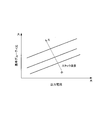
- FIG. 5 is a map for calculating the reference duty ratio based on the load of the fuel cell stack and the stack temperature.
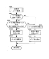
- FIG. 6 is a flowchart for explaining the details of the purge valve opening request signal generation processing.
- FIG. 7 is a flowchart illustrating details of the purge valve opening / closing process.
- FIG. 1 is a schematic diagram of a fuel cell system according to an embodiment of the present invention.
- FIG. 2 is a diagram for explaining a purge amount calculation method according to an embodiment of the present invention.
- FIG. 3 is a diagram illustrating gas in
- FIG. 8 is a flowchart for explaining the details of the purge flow rate estimation process.
- FIG. 9 is a map for calculating the amount of gas per calculation period that has flowed out of the anode system when the purge valve is opened, based on the amount of decrease in the anode pressure.
- FIG. 10 is a map for calculating the amount of hydrogen per operation cycle consumed in the fuel cell stack by power generation when the purge valve is opened based on the output current.
- FIG. 11 is a diagram illustrating a method for calculating the purge flow rate.
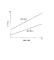
- FIG. 12 is a diagram showing the threshold value of the purge flow rate.
- FIG. 13 is a flowchart for explaining the details of the high-load purge process.
- FIG. 9 is a map for calculating the amount of gas per calculation period that has flowed out of the anode system when the purge valve is opened, based on the amount of decrease in the anode pressure.
- FIG. 10 is a map for calculating the amount of hydrogen per
- FIG. 14A is a flowchart illustrating control of a hydrogen supply valve according to an embodiment of the present invention.
- FIG. 14B is a map for calculating the pulsation upper and lower limit pressures based on the target output current.
- FIG. 15 is a time chart showing purge control when the operation region is the normal region and the purge flow rate is equal to or higher than the threshold value.
- FIG. 16 is a time chart showing purge control when the operation region is the normal region and the purge flow rate is less than the threshold value.
- FIG. 17 is a time chart showing purge control when the operation region is a high load region and the purge flow rate is equal to or higher than the threshold value.
- a fuel cell is configured by sandwiching an electrolyte membrane between an anode electrode (fuel electrode) and a cathode electrode (oxidant electrode).
- the fuel cell generates power by receiving an anode gas (fuel gas) containing hydrogen in the anode electrode and a cathode gas (oxidant gas) containing oxygen in the cathode electrode.
- the electrode reaction that proceeds in both the anode electrode and the cathode electrode is as follows.
- Anode electrode 2H 2 ⁇ 4H + + 4e ⁇ (1)
- Cathode electrode 4H + + 4e ⁇ + O 2 ⁇ 2H 2 O (2)
- the fuel cell generates an electromotive force of about 1 volt by the electrode reactions (1) and (2).
- a fuel cell When a fuel cell is used as a power source for automobiles, it requires a large amount of power, so it is used as a fuel cell stack in which several hundred fuel cells are stacked. Then, a fuel cell system that supplies anode gas and cathode gas to the fuel cell stack is configured, and electric power for driving the vehicle is taken out.
- FIG. 1 is a schematic diagram of a fuel cell system 100 according to an embodiment of the present invention.
- the fuel cell system 100 includes a fuel cell stack 1, a cathode gas supply / discharge device 2, an anode gas supply / discharge device 3, and a controller 4.
- the fuel cell stack 1 is formed by stacking a plurality of fuel cells, and receives the supply of anode gas and cathode gas to generate electric power necessary for driving the vehicle.
- the cathode gas supply / discharge device 2 includes a cathode gas supply passage 21, a cathode gas discharge passage 22, a filter 23, an air flow sensor 24, a cathode compressor 25, a cathode pressure sensor 26, and a water recovery device (Water Recovery ⁇ Device; (Hereinafter referred to as “WRD”) 27 and a cathode pressure regulating valve 28.
- the cathode gas supply / discharge device 2 supplies cathode gas to the fuel cell stack 1 and discharges cathode off-gas discharged from the fuel cell stack 1 to the outside.
- the cathode gas supply passage 21 is a passage through which the cathode gas supplied to the fuel cell stack 1 flows. One end of the cathode gas supply passage 21 is connected to the filter 23, and the other end is connected to the cathode gas inlet hole of the fuel cell stack 1.
- the cathode gas discharge passage 22 is a passage through which the cathode off gas discharged from the fuel cell stack 1 flows. One end of the cathode gas discharge passage 22 is connected to the cathode gas outlet hole of the fuel cell stack 1, and the other end is an open end.
- Cathode off gas is a mixed gas of cathode gas and water vapor generated by electrode reaction.
- the filter 23 removes foreign matters in the cathode gas taken into the cathode gas supply passage 21.
- the air flow sensor 24 is provided in the cathode gas supply passage 21 upstream from the cathode compressor 25.
- the air flow sensor 24 detects the flow rate of the cathode gas supplied to the cathode compressor 25 and finally supplied to the fuel cell stack 1.
- the cathode compressor 25 is provided in the cathode gas supply passage 21.
- the cathode compressor 25 takes air (outside air) as cathode gas through the filter 23 into the cathode gas supply passage 21 and supplies it to the fuel cell stack 1.
- the cathode pressure sensor 26 is provided in the cathode gas supply passage 21 between the cathode compressor 25 and the WRD 27.
- the cathode pressure sensor 26 detects the pressure of the cathode gas supplied to the fuel cell stack 1 (hereinafter referred to as “cathode pressure”).
- the WRD 27 is connected to each of the cathode gas supply passage 21 and the cathode gas discharge passage 22, collects moisture in the cathode off-gas flowing through the cathode gas discharge passage 22, and cathode that flows through the cathode gas supply passage 21 with the collected moisture. Humidify the gas.
- the cathode pressure regulating valve 28 is provided in the cathode gas discharge passage 22 downstream of the WRD 27.
- the cathode pressure regulating valve 28 is controlled to be opened and closed by the controller 4 and adjusts the pressure of the cathode gas supplied to the fuel cell stack 1.
- the cathode pressure is basically controlled to a desired pressure (target cathode pressure) by adjusting the rotational speed of the cathode compressor 25 and the opening of the cathode pressure regulating valve 28.
- the anode gas supply / discharge device 3 supplies anode gas to the fuel cell stack 1 and discharges anode off-gas discharged from the fuel cell stack 1 to the cathode gas discharge passage 22.
- the anode gas supply / discharge device 3 includes a high-pressure hydrogen tank 31, an anode gas supply passage 32, a hydrogen supply valve 33, an anode pressure sensor 34, an anode gas discharge passage 35, and a purge valve 36.
- the high pressure hydrogen tank 31 stores the anode gas supplied to the fuel cell stack 1 in a high pressure state.
- the anode gas supply passage 32 is a passage for supplying the anode gas discharged from the high-pressure hydrogen tank 31 to the fuel cell stack 1.
- One end of the anode gas supply passage 32 is connected to the high-pressure hydrogen tank 31, and the other end is connected to the anode gas inlet hole of the fuel cell stack 1.
- the hydrogen supply valve 33 is provided in the anode gas supply passage 32.
- the hydrogen supply valve 33 is controlled to be opened and closed by the controller 4 and adjusts the pressure of the anode gas supplied to the fuel cell stack 1 to a desired pressure. Further, the flow rate of the anode gas supplied to the fuel cell stack 1 is also controlled by controlling the opening and closing of the hydrogen supply valve 33.
- the anode pressure sensor 34 is provided in the anode gas supply passage 32 downstream of the hydrogen supply valve 33.
- the anode pressure sensor 34 is a pressure detection unit that detects the pressure in the anode gas supply passage 32 downstream of the hydrogen supply valve 33.
- the pressure detected by the anode pressure sensor 34 is used as the pressure in the anode system from the hydrogen supply valve 33 to the purge valve 36 (hereinafter referred to as “anode pressure”).
- the anode gas discharge passage 35 is a passage through which the anode off gas discharged from the fuel cell stack 1 flows.
- the anode off gas is a mixed gas of surplus hydrogen (anode gas) that has not been used in the electrode reaction and nitrogen or water vapor that has permeated from the cathode electrode side to the anode electrode side through the electrolyte membrane.
- One end of the anode gas discharge passage 35 is connected to the anode gas outlet hole of the fuel cell stack 1, and the other end is connected to the cathode gas discharge passage 22.
- the anode off gas discharged to the cathode gas discharge passage 22 is mixed with the cathode off gas in the cathode gas discharge passage 22 and discharged to the outside of the fuel cell system 100. Since the anode off gas contains surplus hydrogen that has not been used for the electrode reaction, the hydrogen concentration in the exhaust gas is determined in advance by mixing with the cathode off gas and discharging it to the outside of the fuel cell system 100. It is made to become below the predetermined concentration.
- the purge valve 36 is provided in the anode gas discharge passage 35.
- the purge valve 36 is controlled to be opened and closed by the controller 4 and controls the flow rate of anode off-gas discharged from the anode system to the cathode gas discharge passage 22 (hereinafter referred to as “purge flow rate”).
- the controller 4 includes a microcomputer having a central processing unit (CPU), a read only memory (ROM), a random access memory (RAM), and an input / output interface (I / O interface).
- CPU central processing unit
- ROM read only memory
- RAM random access memory
- I / O interface input / output interface
- the controller 4 includes an accelerator stroke sensor 41 that detects the amount of depression of the accelerator pedal (hereinafter referred to as “accelerator operation amount”), and cooling water that cools the fuel cell stack 1. Signals from various sensors for detecting the operating state of the fuel cell system 100 such as a temperature sensor 42 for detecting temperature (hereinafter referred to as “stack temperature”) and a current sensor 43 for detecting output current of the fuel cell stack 1 are received. Entered.
- the controller 4 calculates the target output current of the fuel cell stack 1 based on the operating state of the fuel cell system 100. Specifically, based on the required power of a travel motor (not shown) for driving the vehicle, the required power of auxiliary equipment such as the cathode compressor 25, and the charge / discharge request of a battery (not shown), the fuel cell The target output current of the stack 1 is calculated.
- the controller 4 performs a pulsation operation that periodically raises or lowers the anode pressure based on the operation state of the fuel cell system 100.
- the anode pressure is periodically raised and lowered within the range of the pulsation upper limit pressure and the pulsation lower limit pressure set according to the target output current of the fuel cell stack 1 to pulsate the anode pressure.
- liquid water in the anode system is discharged out of the anode system to ensure drainability when the anode pressure is increased.
- the purge valve 36 is opened, nitrogen or the like accumulated in the anode system is discharged from the anode system as the anode off-gas, so that the hydrogen concentration in the anode system increases (recovers). That is, the hydrogen concentration in the anode system changes in accordance with the amount of anode off-gas discharged from the anode system through the purge valve 36 (hereinafter referred to as “purge amount”), and specifically, as the purge amount increases. The hydrogen concentration in the anode system increases.
- the purge flow rate (or purge amount) that can manage the hydrogen concentration in the anode system to a hydrogen concentration (target hydrogen concentration; for example, 60%) that does not cause a voltage drop according to the load of the fuel cell stack 1. Is previously obtained by experiments or the like. Then, the purge flow rate when the purge valve 36 is opened is estimated, and the estimated purge flow rate is compared with the threshold value. If the estimated purge flow rate is equal to or less than the threshold value, it is determined that the purge amount necessary for managing the hydrogen concentration in the anode system to the target hydrogen concentration is insufficient, and additional purge is performed.
- the purge amount has flowed out of the anode system within the period.
- the gas amount is estimated, and the gas amount obtained by subtracting the hydrogen amount consumed by the power generation within the period from the gas amount is used as the amount of anode off-gas discharged from the anode system through the purge valve 36, that is, the purge amount. It can be estimated. Note that the purge flow rate is obtained by dividing the purge amount by the period.
- the gas flowing out from the anode system while the hydrogen supply valve 33 is closed is present in addition to the gas flowing out through the purge valve 36 (hereinafter referred to as “purge gas”) and hydrogen consumed by power generation.
- purge gas hydrogen permeated from the anode electrode side through the electrolyte membrane to the cathode electrode side
- permeated hydrogen hydrogen permeated from the anode electrode side through the electrolyte membrane to the cathode electrode side
- water vapor condensed in the anode system to become liquid water.
- permeated hydrogen contributes to lowering the hydrogen concentration in the anode system.
- the amount permeated through the electrolyte membrane is not small.
- the purge gas contributes to increasing the hydrogen concentration in the anode system, while the permeated hydrogen contributes to decreasing the hydrogen concentration in the anode system.
- the hydrogen concentration in the anode system should normally recover as the purge amount increases, but the recovery amount decreases. Become. Therefore, if this permeated hydrogen amount is ignored and included in the purge amount, the actual hydrogen concentration in the anode system will be lower than expected even though the purge flow rate is above the threshold value. As a result, an unexpected voltage drop may occur.
- the purge amount calculation method according to this embodiment will be described with reference to FIGS.
- FIG. 2 is a diagram illustrating a purge amount calculation method according to this embodiment.
- FIG. 3 is a view for explaining gas inflow and outflow in the anode system while the hydrogen supply valve 33 is closed.
- the pressure drop during the period when the purge valve 36 is opened while the hydrogen supply valve 33 is closed and the pressure during the period when the purge valve 36 is closed while the hydrogen supply valve 33 is closed. Based on the decrease, only the gas flowing out through the purge valve 36 (purge gas) is calculated as the purge amount.
- the purge valve 36 is opened from time t11 to time t13, and the purge valve 36 is closed from time t13 to time t14.
- the anode pressure is changed regardless of whether the purge valve 36 is open or closed. Explain the factors.
- the first factor is hydrogen in the anode system consumed by power generation while the hydrogen supply valve 33 is closed.
- the anode pressure decreases due to the power consumption.
- the second factor is that liquid water evaporates into water vapor in the anode system, or conversely, water vapor condenses into liquid water.
- the anode pressure varies depending on the balance between evaporation and condensation.
- the third factor is that hydrogen that has permeated from the anode electrode side to the cathode electrode side through the electrolyte membrane (permeated hydrogen), or conversely, from the cathode electrode side to the anode electrode side through the electrolyte membrane. Nitrogen and oxygen.
- the anode pressure changes depending on the balance of the permeated gas.
- the purge valve 36 is opened from time t11 to time t13, in addition to these three factors, the anode pressure decreases due to the gas flowing out through the purge valve 36 (purge gas). Due to the structure of the purge valve 36, when the purge valve 36 is opened, the liquid water is first discharged, and then the anode off-gas is discharged as the purge gas. Therefore, as shown in FIG. The anode off gas is discharged from
- the above three periods are included in the period.
- the amount of gas in the anode system lost due to the factors is determined. By dividing this gas amount by the purge valve closing period, the amount of gas in the anode system per unit time lost due to the above three factors can be calculated.
- the amount of gas in the anode system lost by the purge is obtained during the period. Then, this gas amount is divided by the purge valve opening period to calculate the amount of gas in the anode system per unit time lost by purging in addition to the above three factors during the purge valve opening period.
- the amount of gas in the anode system per unit time lost due to the above three factors is basically the same as the purge valve closing period. it is conceivable that.
- the purge valve is used to calculate the amount of gas in the anode system per unit time lost by purging (the flow rate of gas flowing out of the anode system during the purge valve opening period). If the amount of gas in the anode system per unit time lost due to the above three factors during the valve closing period (the flow rate of gas flowing out of the anode system during the purge valve closing period) is subtracted, the gas flows out through the purge valve 36. It is possible to accurately calculate the flow rate of only the gas (purge gas).
- the purge valve 36 in order to estimate the purge amount or the purge flow rate, it is necessary to open and close the purge valve 36 while the hydrogen supply valve 33 is closed. Therefore, if the purge valve 36 is arbitrarily opened / closed regardless of the open / closed state of the hydrogen supply valve 33, the estimated frequency of the purge amount or the purge flow rate may not be ensured.
- the opening and closing of the purge valve 36 is controlled so that the purge valve 36 is opened while the hydrogen supply valve 33 is closed.
- FIG. 4 is a flowchart illustrating purge control according to the present embodiment.
- the controller 4 repeatedly executes this routine at a predetermined calculation cycle.
- the controller 4 refers to the map of FIG. 5 and calculates the reference duty ratio based on the load (output current) of the fuel cell stack 1 and the stack temperature.
- the reference duty ratio can stably generate power for each load when the purge period is fixed to a certain value (reference purge period; in this embodiment, it is set to 5 seconds, but can be changed as appropriate).
- the duty ratio of the purge valve 36 which is obtained in advance through experiments or the like.
- the reference duty ratio is the duty ratio of the purge valve 36 that can manage the hydrogen concentration in the anode system to the target hydrogen concentration.
- the reference duty ratio may be calculated based only on the load (output current) of the fuel cell stack 1.
- step S200 the controller 4 performs a process of generating a valve opening request signal for the purge valve 36 based on the reference duty ratio. Details of the purge valve opening request signal generation processing will be described later with reference to FIG.
- step S300 the controller 4 performs a process of actually opening and closing the purge valve 36 when the hydrogen supply valve 33 is closed (when the anode gas supply is stopped) based on the purge valve opening request signal or the like.
- the details of the opening / closing process of the purge valve 36 will be described later with reference to FIG.
- step S400 the controller 4 estimates the purge flow rate based on the pressure drop degree when the purge valve 36 is opened and when the purge valve 36 is closed during pulsation pressure reduction (when the anode gas supply is stopped). Perform the process. Details of the purge flow rate estimation processing will be described later with reference to FIG.
- FIG. 6 is a flowchart for explaining the details of the purge valve opening request signal generation processing.
- step S201 the controller 4 calculates an integrated value of the time during which a later-described purge valve opening request signal is ON (hereinafter referred to as “purge valve opening request ON time”) at a predetermined reference purge cycle. It is determined whether the divided value is larger than the reference duty ratio. That is, the controller 4 determines whether or not the ratio of the purge valve opening request ON time in the reference purge cycle is larger than the reference duty ratio.
- the controller 4 performs the process of step S202 if the division value is equal to or less than the reference duty ratio, and performs the process of step S203 if it is greater than the reference duty ratio.
- step S202 the controller 4 turns on the purge valve opening request signal.
- step S203 the controller 4 turns off the purge valve opening request signal.
- step S204 the controller 4 integrates the time during which the purge valve opening request signal is ON, and calculates it as the purge valve opening request ON time.
- step S205 the controller 4 determines whether or not one reference purge period has elapsed. That is, for example, when the reference purge cycle is set to 5 seconds, it is determined whether 5 seconds have elapsed since the start of counting the reference purge cycle. The controller 4 ends the current process if one reference purge period has not elapsed, and performs the process of step S206 if it has elapsed.
- step S206 the controller 4 resets the purge valve opening request ON time calculated in step S204 to zero, and also resets the reference purge cycle count to zero.
- FIG. 7 is a flowchart for explaining the details of the purge valve opening / closing process.
- step S301 the controller 4 calculates the purge valve opening request ON time separately from the above-described step S204.
- step S302 the controller 4 determines whether or not the hydrogen supply valve 33 is opened.
- the controller 4 performs the process of step S302.
- the controller 4 performs the process of step S309.
- the determination in step S302 is basically performed in this embodiment so that the purge valve 36 is opened when the anode gas supply is stopped.
- step S303 the controller 4 determines whether or not the operation region of the fuel cell stack 1 is a high load region. For example, the controller 4 determines that the load region is a high load region when the output current is larger than a predetermined current. If the operation region of the fuel cell stack 1 is a high load region, the controller 4 performs the process of step S600, and otherwise performs the process of step S304.
- step S600 the controller 4 performs an opening / closing process of the purge valve 36 performed in the high load region.
- the details of the high load purge process will be described later with reference to FIG. 13.
- the liquid water accumulated in the anode system increases in the high load region than in the normal region. Due to the structure of the purge valve 36, when the purge valve 36 is opened, the liquid water is first discharged from the anode system, and then the anode off-gas is discharged. Therefore, in the high load region, the purge valve 36 can be opened even when the pulsation is increased, and the liquid water in the anode system is surely discharged from the anode system, and then the anode off gas is properly discharged from the anode system. I try to do it.
- step S304 the controller 4 closes the purge valve 36.
- step S305 the controller 4 determines whether the purge valve opening continuation flag is ON.
- the controller 4 performs the process of step S306 if the purge valve open continuation flag is ON, and ends the current process if it is OFF.
- the purge valve open continuation flag is turned on until the purge valve open time when the anode gas supply is stopped exceeds a second predetermined value that is preset as a time for actually opening the purge valve 36 when the anode gas supply is stopped. Flag.
- This purge valve open continuation flag indicates, for example, the current purge valve opening time when the purge valve 36 is opened when the anode gas supply is stopped and the anode gas supply is started before the second predetermined value elapses. This flag is set to take over. Thus, the purge valve 36 can be opened (divided purge) for the remaining time when the anode gas supply is stopped next time.
- step S306 the controller 4 determines whether or not the purge valve opening request ON time calculated in step S301 is equal to or greater than a first predetermined value set in advance.
- the controller 4 performs the process of step S307 if the purge valve opening request ON time is greater than or equal to the first predetermined value, and performs the process of step S308 if it is less than the first predetermined value.
- step S307 the controller 4 turns on the purge valve opening command.
- the initial value of the purge valve opening command is set to OFF.
- the purge valve 36 is actually opened. Thereby, the purge valve 36 can be opened in conjunction with the closing of the water supply valve.
- the hydrogen supply valve 33 is closed, a certain amount of time is required to open the purge valve 36 to ensure drainage, and the anode off-gas ensures that the purge valve 36 is turned on while the purge valve is open. This is so that it can be discharged through.
- the reference duty ratio becomes smaller as the output current is lower, so that the time until the purge valve opening command is turned on can be lengthened as the output current is lower. That is, the interval at which the purge valve opening command is issued is changed based on the output current, and the interval (purge interval) from when the purge valve is closed until it is opened becomes longer as the output current is lower.
- the output current is low, the cathode pressure is also low, so that the amount of nitrogen or the like permeating from the cathode electrode side is small. For this reason, the purge interval is lengthened as the output current is lower, and the time for opening the purge valve 36 necessary for estimating the purge flow rate is secured when the hydrogen supply valve 33 is closed.
- step S308 the controller 4 turns off the purge valve opening command.
- step S309 the controller 4 determines whether or not the purge valve opening command is ON.
- the controller 4 performs the process of step S310 if the purge valve opening command is OFF, and performs the process of step S311 if it is ON.
- step S310 the controller 4 closes the purge valve 36.
- the purge valve 36 is not opened even when the anode gas supply is stopped until the purge valve opening request ON time becomes equal to or greater than the first predetermined value.
- step S311 the controller 4 opens the purge valve 36.
- step S312 the controller 4 integrates the time during which the purge valve 36 is opened and calculates the purge valve opening time.
- step S313 the controller 4 determines whether or not the purge valve opening time calculated in step S312 is equal to or greater than a second predetermined value that is preset as a time for actually opening the purge valve 36 when the anode gas supply is stopped. To do.
- the purge valve opening request ON time becomes equal to or longer than the first predetermined value
- the purge valve 36 is opened by the second predetermined value.
- the first predetermined value and the second predetermined value are set to the same value, but may be set to different values.
- the first predetermined value and the second predetermined value are obtained in advance through experiments or the like as values (for example, 0.5 seconds) at which the hydrogen concentration in the anode system can be managed to the target hydrogen concentration and the purge flow rate can be estimated accurately. be able to.
- the controller 4 performs the process of step S314 if the purge valve opening time is less than the second predetermined value, and performs the process of step S316 if the purge valve opening time is greater than or equal to the second predetermined value.
- step S314 the controller 4 turns on the purge valve open continuation flag.
- step S315 the controller 4 turns off the boosting flag.
- This boosting flag is a flag used in the high load purge process.
- step S316 the controller 4 resets the purge valve opening time calculated in the purge valve opening / closing process to zero.
- step S317 the controller 4 turns off the purge valve opening continuation flag.
- step S318 the controller 4 turns off the purge valve opening command.
- FIG. 8 is a flowchart for explaining the details of the purge flow rate estimation process.
- step S401 the controller 4 determines whether or not the hydrogen supply valve 33 is closed. If the hydrogen supply valve 33 is closed, the controller 4 performs the processing after step S402 in order to acquire data for estimating the purge flow rate. On the other hand, if the hydrogen supply valve 33 is open, the controller 4 performs the processing after step S409 in order to estimate the purge flow rate based on the acquired data.
- step S402 the controller 4 determines whether or not the purge valve 36 is open.
- the controller 4 performs the process of step S403 if the purge valve 36 is open, and performs the process of step S406 if the purge valve 36 is closed.
- step S403 the controller 4 calculates the amount of gas per operation period that has flowed out of the anode system when the purge valve is opened based on the decrease in the anode pressure, and adds this amount of gas to the previous value to add the purge valve. Calculate the amount of outflow gas when the valve is opened.
- the amount of gas per operation cycle that flows out from the anode system when the purge valve is opened is, for example, the amount of decrease in anode pressure (previous value of anode pressure ⁇ current value of anode pressure), and the amount of gas that flows out of the anode system.
- 9 can be calculated based on the amount of decrease in the anode pressure by previously creating a map shown in FIG. In FIG. 9, the amount of gas flowing out from the anode system is corrected by the stack temperature, but correction by the stack temperature is not necessarily required.
- the amount of gas is determined by substituting, for example, the number of moles of gas in the anode system obtained by substituting the previous value of the anode pressure into the gas state equation and the current value of the anode pressure. It can also be obtained by calculating the change in the number of moles of gas.
- step S404 the controller 4 calculates the amount of hydrogen per calculation cycle consumed in the fuel cell stack 1 by power generation when the purge valve is opened based on the detected value (output current) of the current sensor 43, and this hydrogen The amount of power generation consumed when the purge valve is opened is calculated by adding the amount to the previous value.
- the amount of hydrogen consumed in the fuel cell stack 1 by the power generation when the purge valve is opened is, for example, created in advance by an experiment or the like as a map shown in FIG. 10 in which the output current and the amount of consumed hydrogen are associated with each other. It is possible to calculate based on the output current by referring to this map. Further, for example, it can be obtained by calculating the molar mass of hydrogen consumed by substituting the output current, the calculation cycle, and the number of fuel cells into the calculation formula using the Faraday constant.
- step S405 the controller 4 calculates the purge valve opening time separately from step S312.
- step S406 the controller 4 calculates the amount of gas per calculation period that has flowed out of the anode system when the purge valve is closed, based on the decrease in the anode pressure, and adds this amount of gas to the previous value. Calculate the outflow gas amount when the valve is closed.
- step S407 the controller 4 calculates the amount of hydrogen per calculation cycle consumed in the fuel cell stack 1 by power generation when the purge valve is closed based on the detected value (output current) of the current sensor 43, and this hydrogen The amount of generated power consumption when the purge valve is closed is calculated by adding the amount to the previous value.
- step S408 the controller 4 integrates the time during which the purge valve 36 is closed, and calculates it as the purge valve closing time.
- step S409 the controller 4 determines whether or not the amount of data for calculating the purge flow rate is sufficient. Specifically, it is determined whether or not the purge valve opening time and the purge valve closing time calculated in step S405 and step S408 are longer than a predetermined time (for example, 0.5 seconds) set in advance, respectively. . If the amount of data is sufficient, the controller 4 performs the process of step S410, and if not enough, ends the current process. Therefore, if the amount of data is insufficient, the purge flow rate is estimated based on not only data for one pulsation period but also pressure change data for pulsation multiple periods.
- a predetermined time for example, 0.5 seconds
- step S410 the controller 4 calculates the purge flow rate based on the data acquired in steps S403 to S408.
- the purge flow rate is calculated by performing the calculation shown in FIG.
- step S411 the controller 4 refers to the map of FIG. 12 and determines whether or not the calculated purge flow rate is equal to or greater than a preset threshold value. In other words, it is determined whether the purge amount is sufficient.
- the controller 4 performs the process of step S412 if the purge flow rate is equal to or greater than the threshold, and performs the process of step S413 if it is less than the threshold.
- the threshold value is an interval at which a purge valve opening command is issued (an interval from when a purge valve opening command is issued until the next purge valve opening command is issued; hereinafter referred to as “purge interval”). It is corrected so as to become smaller as the length becomes longer.
- the purge interval is the longer the period from when the purge valve 36 is opened until the next is opened, the more liquid water is accumulated in the anode system. Therefore, as the purge interval becomes longer, the purge amount discharged when the purge valve 36 is opened becomes relatively smaller.
- the purge valve 36 since the purge valve 36 is opened in accordance with the open / closed state of the hydrogen supply valve 33, the interval until the purge valve 36 is opened varies. In this case, the purge amount decreases when the purge interval is longer than when the purge interval is short because the amount of liquid water in the anode system increases due to the longer purge interval. Therefore, the frequency at which it is determined that the purge is insufficient is reduced by reducing the threshold value as the interval for issuing the purge valve opening command is longer.
- the threshold value decreases as the load of the fuel cell stack 1 increases, and the tendency seems to be reversed. This is because the purge flow rate is on the horizontal axis, and the purge flow rate is different for each load.
- the purge amount itself multiplied by the valve opening time of the purge valve 36 corresponding to the reference duty ratio increases as the load of the fuel cell stack 1 increases.
- step S412 the controller 4 subtracts the purge valve opening time from the purge valve opening request ON time calculated in step S301.
- step S413 the controller 4 maintains the purge valve opening request ON time calculated in step S301 as it is. This is because when it is determined that the purge flow rate is less than the threshold value, it is necessary to perform further purge for stable power generation, so that the additional purge can be performed in the next process.
- the purge interval is made shorter than usual by not subtracting the purge valve opening time from the purge valve opening request ON time,
- the purge valve opening request ON time is increased more than when the purge flow rate is equal to or greater than the threshold (when the purge amount is sufficient).
- the time for opening the purge valve 36 is increased by the increased amount, that is, the amount not subtracted.
- step S414 the controller 4 resets the data in steps S403 to S408 to zero.
- FIG. 13 is a flowchart for explaining the details of the high-load purge process.
- step S601 the controller 4 determines whether or not the purge valve opening command is ON.
- the controller 4 performs the process of step S602 if the purge valve opening command is ON, and performs the process of step S605 if it is OFF.
- step S602 the controller 4 determines whether or not the purge valve opening time calculated in step S312 is zero or whether the valve opening flag during pressure increase is ON. If either one is established, the controller 4 performs the process of step S603, and if neither is established, the controller 4 performs the process of step S605.
- step S603 the controller 4 turns on the valve opening flag during boosting.
- step S604 the controller 4 opens the purge valve 36.
- step S605 the controller 4 integrates the time during which the purge valve 36 is opened and calculates the purge valve opening time.
- step S606 the controller 4 turns off the valve opening flag during pressure increase.
- step S607 the controller 4 closes the purge valve 36.
- the purge valve 36 is opened even when the hydrogen supply valve 33 is being opened. This is because the liquid water in the fuel cell stack 1 increases when the load is high, so that the drainage of the liquid water is ensured by opening the purge valve 36 from the time when the hydrogen supply valve 33 is opened. is there.
- the load is high, the amount of hydrogen consumed by power generation increases, so the rate of decrease in the anode pressure after closing the hydrogen supply valve 33 increases and the time for pressure reduction also decreases. Therefore, by opening the purge valve 36 during the pressure increase to increase the liquid water discharge efficiency, the purge gas can be reliably discharged through the purge valve 36 after the hydrogen supply valve is closed even if the pressure reduction time is shortened. be able to. Therefore, the estimation accuracy of the purge flow rate can be improved.
- FIG. 14A is a flowchart illustrating control of the hydrogen supply valve 33 according to the present embodiment.
- step S1 the controller 4 sets the pulsation upper limit pressure and the pulsation lower limit pressure of the anode pressure based on the target output current of the fuel cell stack 1 with reference to the map of FIG. 14B.
- step S2 the controller 4 determines whether or not the anode pressure is equal to or higher than the pulsation upper limit pressure. If the anode pressure is equal to or higher than the pulsation upper limit pressure, the controller 4 performs the process of step S3 to reduce the anode pressure. On the other hand, if the anode pressure is less than the pulsation upper limit pressure, the process of step S4 is performed.
- step S3 the controller 4 sets the target anode pressure to the pulsation lower limit pressure.
- step S4 the controller 4 determines whether or not the anode pressure is equal to or lower than the pulsation lower limit pressure. If the anode pressure is equal to or lower than the pulsation lower limit pressure, the controller 4 performs the process of step S5 to increase the anode pressure. On the other hand, if the anode pressure is higher than the pulsation lower limit pressure, the process of step S6 is performed.
- step S5 the controller 4 sets the target anode pressure to the pulsation upper limit pressure.
- step S6 the controller 4 sets the target anode pressure to the same target anode pressure as the previous time.
- step S7 when the pulsation lower limit pressure is set as the target anode pressure, the controller 4 feedback-controls the hydrogen supply valve 33 so that the anode pressure becomes the pulsation lower limit pressure.
- the opening of the hydrogen supply valve 33 is normally fully closed, and the supply of anode gas from the high-pressure hydrogen tank 31 to the fuel cell stack 1 is stopped.
- the anode pressure decreases due to the consumption of anode gas in the fuel cell stack 1 due to power generation.
- the controller 4 feedback-controls the hydrogen supply valve 33 so that the anode pressure is increased to the pulsation upper limit pressure.
- the hydrogen supply valve 33 is opened to a desired opening, the anode gas is supplied from the high-pressure hydrogen tank 31 to the fuel cell stack 1, and the anode pressure rises.
- the time chart of FIG. 15 is a time chart when the operation region is the normal region and the purge flow rate is greater than or equal to the threshold value.
- the time chart of FIG. 16 is a time chart when the operation region is the normal region and the purge flow rate is less than the threshold value.
- the purge valve opening request signal is generated by the purge valve opening request signal generation process so that the purge valve opening request signal is turned ON by the reference duty ratio during the reference purge period.
- the time during which the purge valve opening request signal is ON is integrated and calculated as the purge valve opening request ON time.
- the purge valve opening command ON time becomes equal to or greater than the first predetermined value at time t1
- the purge valve opening command is turned on when the hydrogen supply valve 33 is opened at the subsequent time t2 (FIG. 15B). (FIG. 15F).
- the purge valve 36 is opened (FIG. 15C).
- the time during which the purge valve 36 is opened is added up and calculated as the purge valve opening time.
- the purge valve opening command is turned OFF (FIG. 15F), and the purge valve 36 is closed (FIG. 15C).
- the data for estimating the purge flow rate that is, the outflow gas amount and the power generation hydrogen consumption amount when the purge valve is opened are calculated.
- the purge flow rate is calculated based on the acquired data (FIG. 15 (I)).
- the purge valve opening request ON time is maintained as it is at time t6. Therefore, the purge valve opening command is turned ON at time t6, and the purge valve 36 can be opened at time t7.
- the purge interval is made narrower than the normal purge interval, and the purge valve 36 is opened again when the hydrogen supply valve 33 is closed after the purge flow rate is estimated, and additional purge is performed. To do. Therefore, the hydrogen concentration in the anode system can be managed to a hydrogen concentration at which power generation is stable.
- FIG. 17 is also a time chart for explaining the purge control according to the present embodiment.
- the time chart of FIG. 17 is a time chart when the operation region is a high load region and the purge flow rate is greater than or equal to the threshold value.
- the purge valve opening command is turned ON (FIG. 17E).
- the operation region is a high load region, it is determined by the high load purge process whether the purge valve opening time is zero or the valve opening flag during pressure increase is ON.
- the pressure increasing flag is turned ON (FIG. 17H), and the purge valve 36 is opened while the hydrogen supply valve 33 is opened (FIG. 17B )).
- the purge valve 36 is opened while the hydrogen supply valve 33 is open, so that liquid water can be discharged reliably, and the purge gas can be reliably discharged via the purge valve 36 after the hydrogen supply valve is closed. Can be discharged. Thereby, the estimation accuracy of the purge flow rate can be improved.
- the purge valve opening time reaches the second predetermined value during one pulsation pressure drop. There are times when I don't. In such a case, the purge valve 36 is opened separately, and only the first purge is performed while the hydrogen supply valve 33 is opened.
- the fuel cell system 100 includes a hydrogen supply valve 33 (supply valve) that controls the supply of anode gas into the anode system, a purge valve 36 that discharges off-gas from the anode system, and an anode system.
- supply valve supply valve
- purge valve 36 that discharges off-gas from the anode system
- An anode pressure sensor 34 pressure detection unit
- a supply valve control unit that controls opening and closing of the hydrogen supply valve 33 based on the load (output current) of the fuel cell stack 1
- a purge flow rate estimating unit for estimating a purge flow rate of off-gas discharged from the anode system through the purge valve 36 based on a pressure drop in the anode system while the hydrogen supply valve 33 is closed
- a purge valve control unit that opens the purge valve 36 in accordance with the closing of the supply valve 33.
- the purge valve 36 is hydrogenated as compared with the case where the purge valve 36 is arbitrarily opened regardless of the open / closed state of the hydrogen supply valve 33. It is possible to increase the frequency with which the purge valve 36 is opened when the pressure in the anode system drops while the supply valve 33 is closed. Therefore, it is possible to ensure the frequency of estimating the purge flow rate of the off-gas discharged from the anode system through the purge valve 36 based on the pressure drop in the anode system while the hydrogen supply valve 33 is closed.
- the purge valve control unit closes the purge valve 36 (opens the hydrogen supply valve 33) when the purge valve 36 is opened for a predetermined opening time (second predetermined value) while the hydrogen supply valve 33 is closed. Since the purge valve 36 is closed before the valve), the purge valve 36 can be opened and closed while the hydrogen supply valve 33 is closed. Therefore, even when the purge flow rate is estimated based on the pressure drop when the purge valve is opened while the hydrogen supply valve 33 is closed and the pressure drop when the purge valve is closed, the estimated frequency can be secured.
- the purge valve control unit purges the purge valve 36 in accordance with the opening timing of the hydrogen supply valve 33. And the purge valve 36 is opened again while the next hydrogen supply valve 33 is closed. Therefore, while the hydrogen supply valve 33 is closed, the purge valve 36 is opened to ensure the purge flow estimation frequency, and the purge amount necessary to keep the hydrogen concentration in the anode system at a stable hydrogen concentration. Can be ensured.
- the fuel cell system 100 includes a determination unit (controller 4) that determines whether or not the purge amount is insufficient based on the purge flow rate estimated by the purge flow rate estimation unit, and performs purge valve control.
- the unit changes the interval (purge interval) until the purge valve 36 is opened based on the load of the fuel cell stack 1, and opens the purge valve 36 when it is determined that the purge amount is insufficient. Is made shorter than the interval set based on the load of the fuel cell stack 1.
- the purge valve control unit calculates a valve opening request time (reference duty ratio) of the purge valve 36 based on the load of the fuel cell stack 1, and an integrated value of the valve opening request time (purge valve opening request)
- a command to open the purge valve 36 is issued. If it is determined that the purge amount is not insufficient, the integrated value of the valve opening request time is set to open the purge valve 36. Only the valve time is subtracted, and when it is determined that the purge amount is insufficient, the integrated value of the valve opening request time is held as it is.
- the determination unit determines whether the purge amount is insufficient based on the purge flow rate estimated by the purge flow rate estimation unit and the threshold value corresponding to the load of the fuel cell stack 1, and the threshold value is the purge valve. Correction is made so as to decrease as the interval until the valve 36 is opened becomes longer.
- the purge interval is the longer the period from when the purge valve 36 is opened until the next is opened, the more liquid water is accumulated in the anode system. Therefore, as the purge interval becomes longer, the purge amount discharged when the purge valve 36 is opened becomes relatively smaller.
- the purge valve 36 since the purge valve 36 is opened in accordance with the open / closed state of the hydrogen supply valve 33, the interval until the purge valve 36 is opened varies. In this case, the purge amount decreases when the purge interval is longer than when the purge interval is short because the amount of liquid water in the anode system increases due to the longer purge interval.
- the purge valve control unit opens the purge valve 36 while the hydrogen supply valve 33 is open, so the liquid water accumulated in the anode system Can be reliably discharged, and the amount of anode off-gas discharged when the purge valve 36 is opened can be secured. Therefore, the estimation accuracy of the purge flow rate can be improved.
- the purge valve opening time (second predetermined value) elapses for the hydrogen supply valve 33 once closed.
- the purge valve 36 is closed in accordance with the restart timing of the hydrogen supply valve 33, and the purge valve 36 is opened again during the subsequent closing of the hydrogen supply valve 33.
- the purge valve 36 is opened while the hydrogen supply valve 33 is open only during the first purge.
- the purge valve 36 is opened from the next purge when the hydrogen supply valve 33 is closed, thereby ensuring the estimated frequency of the purge flow rate. can do.
- the purge flow rate estimation unit passes through the purge valve 36 and passes through the anode system based on the pressure drop when the purge valve is opened and the pressure drop when the purge valve is closed when the supply of the anode gas into the anode system is stopped. Estimate the purge flow rate of off-gas discharged from Specifically, the purge flow rate estimating unit is configured to estimate a gas flow rate flowing out from the anode system during the purge valve opening period based on a pressure drop when the purge valve is opened, and when the purge valve is closed.
- a second estimation unit that estimates the flow rate of gas flowing out from the anode system regardless of the open / close state of the purge valve 36 based on the pressure drop of the gas, and the gas flow rate estimated by the first estimation unit and the second estimation unit
- the purge flow rate is estimated based on the gas flow rate estimated in (1).
- the flow rate of gas flowing out from the anode system can be estimated from the pressure drop when the purge valve is closed regardless of whether the purge valve 36 is open or closed. From the gas flow rate flowing out from the inside, the flow rate of only off-gas discharged from the anode system through the purge valve 36 can be accurately estimated.
- the purge valve 36 is opened simultaneously with the closing of the hydrogen supply valve 33.
- the purge valve 36 is passed after a predetermined time (for example, 80 milliseconds). 36 may be opened.
- a predetermined time for example, 80 milliseconds.
- the detected value of the anode pressure sensor 34 is used as the pressure in the anode system.
- the pressure in the anode system may be estimated from the opening degree of the hydrogen supply valve 33, for example.
- the pulsation operation for pulsating the anode pressure is performed.
- a fuel cell system in which the anode pressure is constant according to the load of the fuel cell stack may be used.
- the purge valve 36 may be opened and closed at the time of lowering transition when the load is reduced (when the anode pressure is lowered).
- the anode pressure may be pulsated temporarily.
- the purge valve 36 is kept open while the hydrogen supply valve 33 is closed. Purging was carried out in divided portions.
- the purge valve 36 may be closed before the hydrogen supply valve 33 is opened, and purge may be performed until the purge valve opening time reaches the second predetermined value. .
- the anode gas discharge passage 35 and the anode gas supply passage 32 upstream of the purge valve 36 may be connected to circulate the anode off gas.
Landscapes
- Life Sciences & Earth Sciences (AREA)
- Engineering & Computer Science (AREA)
- Manufacturing & Machinery (AREA)
- Sustainable Development (AREA)
- Sustainable Energy (AREA)
- Chemical & Material Sciences (AREA)
- Chemical Kinetics & Catalysis (AREA)
- Electrochemistry (AREA)
- General Chemical & Material Sciences (AREA)
- Fuel Cell (AREA)
Abstract
Description
カソード電極 : 4H++4e-+O2→2H2O ・・・(2)
この(1)(2)の電極反応によって燃料電池は1ボルト程度の起電力を生じる。
Claims (12)
- アノードガス及びカソードガスを燃料電池に供給し、負荷に応じて前記燃料電池を発電させる燃料電池システムであって、
前記燃料電池システムのアノード系内へアノードガスを供給するための供給弁と、
前記アノード系内からオフガスを排出するためのパージ弁と、
前記アノード系内の圧力を推定又は計測する圧力検出部と、
前記燃料電池の負荷に基づいて、前記供給弁の開閉を制御する供給弁制御部と、
前記供給弁の閉弁中のアノード系内の圧力低下に基づいて、前記パージ弁を通って前記アノード系内から排出されるオフガスのパージ流量を推定するパージ流量推定部と、
前記供給弁の閉弁中に合わせて前記パージ弁を開弁するパージ弁制御部と、
を備える燃料電池システム。 - 請求項1に記載の燃料電池システムであって、
前記パージ弁制御部は、前記供給弁の閉弁後、所定時間が経過してから前記パージ弁を開弁する、
燃料電池システム。 - 請求項1又は請求項2に記載の燃料電池システムであって、
前記パージ弁制御部は、前記供給弁の閉弁中に前記パージ弁を所定の開弁時間だけ開弁したら、前記パージ弁を閉弁する、
燃料電池システム。 - 請求項3に記載の燃料電池システムであって、
前記パージ弁制御部は、前記開弁時間が経過する前に前記供給弁が開弁されたときは、前記供給弁の開弁タイミングに合わせて前記パージ弁を閉弁し、次の前記供給弁の閉弁中に再度前記パージ弁を開弁する、
燃料電池システム。 - 請求項1に記載の燃料電池システムであって、
前記パージ弁制御部は、前記供給弁の開弁前に前記パージ弁を閉弁する、
燃料電池システム。 - 請求項1から請求項5までのいずれか1つに記載の燃料電池システムであって、
前記パージ流量推定部によって推定されたパージ流量に基づいて、パージ量が不足しているか否かを判定する判定部を備え、
前記パージ弁制御部は、
前記燃料電池の負荷に基づいて前記パージ弁を開弁するまでの間隔を変更し、
パージ量が不足していると判定されたときは、前記パージ弁を開弁するまでの間隔を、前記燃料電池の負荷に基づいて設定される間隔よりも短くする、
燃料電池システム。 - 請求項6に記載の燃料電池システムであって、
前記パージ弁制御部は、
前記燃料電池の負荷に基づいて前記パージ弁の開弁要求時間を算出し、前記開弁要求時間の積算値が第1所定値以上になったときに前記パージ弁の開弁指令を出し、
パージ量が不足していないと判定されたときは前記開弁要求時間の積算値を前記パージ弁の開弁時間だけ減算し、パージ量が不足していると判定されたときは前記開弁要求時間の積算値をそのまま保持する、
燃料電池システム。 - 請求項6又は請求項7に記載の燃料電池システムであって、
前記判定部は、前記パージ流量推定部によって推定されたパージ流量と、前記燃料電池の負荷に応じた閾値と、に基づいてパージ量が不足しているか否かを判定し、
前記閾値は、前記パージ弁を開弁するまでの間隔が長くなるほど小さくなるように補正される、
燃料電池システム。 - 請求項1から請求項8までのいずれか1つに記載の燃料電池システムであって、
前記パージ弁制御部は、前記燃料電池の負荷が所定負荷よりも高いときは、前記供給弁の開弁中から前記パージ弁を開弁する、
燃料電池システム。 - 請求項9に記載の燃料電池システムであって、
前記パージ弁制御部は、
前記供給弁の開弁中に前記パージ弁を開弁した場合において、前記供給弁がその後閉弁されてから再度開弁されるまでに前記パージ弁の開弁時間が所定の開弁時間を経過していない場合、前記供給弁の再開弁タイミングに合わせて前記パージ弁を閉弁し、その後の前記供給弁の閉弁中に前記パージ弁を再度開弁する、
燃料電池システム。 - 請求項1から請求項10までのいずれか1つに記載の燃料電池システムであって、
前記パージ流量推定部は、
前記供給弁の閉弁中におけるパージ弁開弁時の圧力低下とパージ弁閉弁時の圧力低下とに基づいて、前記パージ流量を推定する、
燃料電池システム。 - 請求項11に記載の燃料電池システムであって、
前記パージ流量推定部は、
前記供給弁の閉弁中におけるパージ弁開弁時の圧力低下に基づいて、パージ弁開弁期間に前記アノード系内から流出するガス流量を推定する第1推定部と、
前記供給弁の閉弁中におけるパージ弁閉弁時の圧力低下に基づいて、パージ弁の開閉状態によらずにアノード系内から流出するガス流量を推定する第2推定部と、
を備え、
前記第1推定部で推定したガス流量と、前記第2推定部で推定したガス流量と、に基づいて前記パージ流量を推定する、
燃料電池システム。
Priority Applications (5)
| Application Number | Priority Date | Filing Date | Title |
|---|---|---|---|
| EP15854564.0A EP3214687B1 (en) | 2014-10-28 | 2015-09-16 | Fuel cell system |
| JP2016556431A JP6458046B2 (ja) | 2014-10-28 | 2015-09-16 | 燃料電池システム |
| CN201580056802.7A CN107078322B (zh) | 2014-10-28 | 2015-09-16 | 燃料电池系统 |
| US15/521,460 US10497955B2 (en) | 2014-10-28 | 2015-09-16 | Fuel cell system |
| CA2965901A CA2965901C (en) | 2014-10-28 | 2015-09-16 | Purge amount of anode off-gas computation system in fuel cell system |
Applications Claiming Priority (2)
| Application Number | Priority Date | Filing Date | Title |
|---|---|---|---|
| JP2014-219712 | 2014-10-28 | ||
| JP2014219712 | 2014-10-28 |
Publications (1)
| Publication Number | Publication Date |
|---|---|
| WO2016067782A1 true WO2016067782A1 (ja) | 2016-05-06 |
Family
ID=55857128
Family Applications (1)
| Application Number | Title | Priority Date | Filing Date |
|---|---|---|---|
| PCT/JP2015/076340 Ceased WO2016067782A1 (ja) | 2014-10-28 | 2015-09-16 | 燃料電池システム |
Country Status (6)
| Country | Link |
|---|---|
| US (1) | US10497955B2 (ja) |
| EP (1) | EP3214687B1 (ja) |
| JP (1) | JP6458046B2 (ja) |
| CN (1) | CN107078322B (ja) |
| CA (1) | CA2965901C (ja) |
| WO (1) | WO2016067782A1 (ja) |
Families Citing this family (7)
| Publication number | Priority date | Publication date | Assignee | Title |
|---|---|---|---|---|
| EP3214684B1 (en) * | 2014-10-28 | 2022-05-04 | Nissan Motor Co., Ltd. | Fuel cell system and control method therefor |
| WO2016067789A1 (ja) * | 2014-10-28 | 2016-05-06 | 日産自動車株式会社 | 燃料電池システム及びその制御方法 |
| CA2965901C (en) * | 2014-10-28 | 2022-03-01 | Nissan Motor Co., Ltd. | Purge amount of anode off-gas computation system in fuel cell system |
| CN113540535A (zh) * | 2020-04-17 | 2021-10-22 | 国家能源投资集团有限责任公司 | 用于氢燃料电池的控制方法、控制系统及氢燃料电池 |
| CN114759233B (zh) * | 2022-05-24 | 2024-01-26 | 苏州溯驭技术有限公司 | 一种适用于氢燃料系统的排氮阀控制方法及其排氮阀系统 |
| CN116364981B (zh) * | 2022-12-27 | 2024-03-26 | 上海氢晨新能源科技有限公司 | 氢燃料电池的阳极压力平衡方法、装置及设备 |
| DE102024121292A1 (de) * | 2024-07-26 | 2026-01-29 | Bayerische Motoren Werke Aktiengesellschaft | Verfahren und Vorrichtung zum Kontrollieren eines Drain/Purge-Ventils in einem Brennstoffzellensystem, Brennstoffzellensystem, Fahrzeug, Computerprogrammprodukt und Speichermedium |
Citations (5)
| Publication number | Priority date | Publication date | Assignee | Title |
|---|---|---|---|---|
| JP2008041329A (ja) * | 2006-08-02 | 2008-02-21 | Toyota Motor Corp | 燃料電池システム |
| JP2008097973A (ja) * | 2006-10-11 | 2008-04-24 | Toyota Motor Corp | 燃料電池システム |
| JP2009037951A (ja) * | 2007-08-03 | 2009-02-19 | Honda Motor Co Ltd | 燃料電池システム及びその運転方法 |
| JP2009193838A (ja) * | 2008-02-15 | 2009-08-27 | Honda Motor Co Ltd | 燃料電池システムおよびその制御方法 |
| WO2013137271A1 (ja) * | 2012-03-12 | 2013-09-19 | 日産自動車株式会社 | 燃料電池システム |
Family Cites Families (9)
| Publication number | Priority date | Publication date | Assignee | Title |
|---|---|---|---|---|
| US20050142400A1 (en) | 2003-12-31 | 2005-06-30 | Nuvera Fuel Cells | Safe purging of water from fuel cell stacks |
| JP5446023B2 (ja) | 2006-08-11 | 2014-03-19 | トヨタ自動車株式会社 | 燃料電池システム |
| CN103098280B (zh) * | 2010-09-09 | 2015-02-04 | 日产自动车株式会社 | 燃料电池系统及其运转方法 |
| US8701468B2 (en) | 2010-12-17 | 2014-04-22 | GM Global Technology Operations LLC | Flow estimation based on anode pressure response in fuel cell system |
| JP5741713B2 (ja) * | 2011-12-28 | 2015-07-01 | 日産自動車株式会社 | 燃料電池システム |
| US20150017562A1 (en) * | 2012-02-29 | 2015-01-15 | Nissan Motor Co., Ltd | Fuel cell system and control method of fuel cell system |
| WO2016067789A1 (ja) * | 2014-10-28 | 2016-05-06 | 日産自動車株式会社 | 燃料電池システム及びその制御方法 |
| CA2965901C (en) * | 2014-10-28 | 2022-03-01 | Nissan Motor Co., Ltd. | Purge amount of anode off-gas computation system in fuel cell system |
| CA2966135C (en) * | 2014-10-28 | 2018-10-16 | Nissan Motor Co., Ltd. | A fuel cell system for estimating a purge amount |
-
2015
- 2015-09-16 CA CA2965901A patent/CA2965901C/en active Active
- 2015-09-16 JP JP2016556431A patent/JP6458046B2/ja active Active
- 2015-09-16 CN CN201580056802.7A patent/CN107078322B/zh active Active
- 2015-09-16 EP EP15854564.0A patent/EP3214687B1/en active Active
- 2015-09-16 WO PCT/JP2015/076340 patent/WO2016067782A1/ja not_active Ceased
- 2015-09-16 US US15/521,460 patent/US10497955B2/en active Active
Patent Citations (5)
| Publication number | Priority date | Publication date | Assignee | Title |
|---|---|---|---|---|
| JP2008041329A (ja) * | 2006-08-02 | 2008-02-21 | Toyota Motor Corp | 燃料電池システム |
| JP2008097973A (ja) * | 2006-10-11 | 2008-04-24 | Toyota Motor Corp | 燃料電池システム |
| JP2009037951A (ja) * | 2007-08-03 | 2009-02-19 | Honda Motor Co Ltd | 燃料電池システム及びその運転方法 |
| JP2009193838A (ja) * | 2008-02-15 | 2009-08-27 | Honda Motor Co Ltd | 燃料電池システムおよびその制御方法 |
| WO2013137271A1 (ja) * | 2012-03-12 | 2013-09-19 | 日産自動車株式会社 | 燃料電池システム |
Also Published As
| Publication number | Publication date |
|---|---|
| CN107078322A (zh) | 2017-08-18 |
| EP3214687B1 (en) | 2019-08-21 |
| EP3214687A4 (en) | 2017-09-06 |
| US20170373334A1 (en) | 2017-12-28 |
| CN107078322B (zh) | 2021-02-02 |
| EP3214687A1 (en) | 2017-09-06 |
| JP6458046B2 (ja) | 2019-01-23 |
| CA2965901C (en) | 2022-03-01 |
| JPWO2016067782A1 (ja) | 2017-07-27 |
| CA2965901A1 (en) | 2016-05-06 |
| US10497955B2 (en) | 2019-12-03 |
Similar Documents
| Publication | Publication Date | Title |
|---|---|---|
| JP6295340B2 (ja) | 燃料電池システム | |
| JP6308305B2 (ja) | 燃料電池システム及びその制御方法 | |
| JP6458046B2 (ja) | 燃料電池システム | |
| JP6299880B2 (ja) | 燃料電池システム及びその制御方法 | |
| US9806359B2 (en) | Fuel cell system and control method therefor | |
| JPWO2014045810A1 (ja) | 燃料電池システム | |
| JP6428777B2 (ja) | 燃料電池システム及び燃料電池システムの圧力損失推定方法 | |
| JP2018092920A (ja) | 燃料電池システムおよびその運転方法 |
Legal Events
| Date | Code | Title | Description |
|---|---|---|---|
| 121 | Ep: the epo has been informed by wipo that ep was designated in this application |
Ref document number: 15854564 Country of ref document: EP Kind code of ref document: A1 |
|
| ENP | Entry into the national phase |
Ref document number: 2016556431 Country of ref document: JP Kind code of ref document: A |
|
| WWE | Wipo information: entry into national phase |
Ref document number: 15521460 Country of ref document: US |
|
| ENP | Entry into the national phase |
Ref document number: 2965901 Country of ref document: CA |
|
| NENP | Non-entry into the national phase |
Ref country code: DE |
|
| REEP | Request for entry into the european phase |
Ref document number: 2015854564 Country of ref document: EP |