WO2016067815A1 - 空気調和機 - Google Patents
空気調和機 Download PDFInfo
- Publication number
- WO2016067815A1 WO2016067815A1 PCT/JP2015/077564 JP2015077564W WO2016067815A1 WO 2016067815 A1 WO2016067815 A1 WO 2016067815A1 JP 2015077564 W JP2015077564 W JP 2015077564W WO 2016067815 A1 WO2016067815 A1 WO 2016067815A1
- Authority
- WO
- WIPO (PCT)
- Prior art keywords
- compressor
- air conditioner
- refrigerant gas
- detection sensor
- abnormality
- Prior art date
- Legal status (The legal status is an assumption and is not a legal conclusion. Google has not performed a legal analysis and makes no representation as to the accuracy of the status listed.)
- Ceased
Links
Images


Classifications
-
- F—MECHANICAL ENGINEERING; LIGHTING; HEATING; WEAPONS; BLASTING
- F24—HEATING; RANGES; VENTILATING
- F24F—AIR-CONDITIONING; AIR-HUMIDIFICATION; VENTILATION; USE OF AIR CURRENTS FOR SCREENING
- F24F11/00—Control or safety arrangements
- F24F11/30—Control or safety arrangements for purposes related to the operation of the system, e.g. for safety or monitoring
- F24F11/32—Responding to malfunctions or emergencies
- F24F11/36—Responding to malfunctions or emergencies to leakage of heat-exchange fluid
-
- F—MECHANICAL ENGINEERING; LIGHTING; HEATING; WEAPONS; BLASTING
- F25—REFRIGERATION OR COOLING; COMBINED HEATING AND REFRIGERATION SYSTEMS; HEAT PUMP SYSTEMS; MANUFACTURE OR STORAGE OF ICE; LIQUEFACTION SOLIDIFICATION OF GASES
- F25B—REFRIGERATION MACHINES, PLANTS OR SYSTEMS; COMBINED HEATING AND REFRIGERATION SYSTEMS; HEAT PUMP SYSTEMS
- F25B13/00—Compression machines, plants or systems, with reversible cycle
-
- F—MECHANICAL ENGINEERING; LIGHTING; HEATING; WEAPONS; BLASTING
- F25—REFRIGERATION OR COOLING; COMBINED HEATING AND REFRIGERATION SYSTEMS; HEAT PUMP SYSTEMS; MANUFACTURE OR STORAGE OF ICE; LIQUEFACTION SOLIDIFICATION OF GASES
- F25B—REFRIGERATION MACHINES, PLANTS OR SYSTEMS; COMBINED HEATING AND REFRIGERATION SYSTEMS; HEAT PUMP SYSTEMS
- F25B49/00—Arrangement or mounting of control or safety devices
- F25B49/02—Arrangement or mounting of control or safety devices for compression type machines, plants or systems
- F25B49/022—Compressor control arrangements
-
- F—MECHANICAL ENGINEERING; LIGHTING; HEATING; WEAPONS; BLASTING
- F25—REFRIGERATION OR COOLING; COMBINED HEATING AND REFRIGERATION SYSTEMS; HEAT PUMP SYSTEMS; MANUFACTURE OR STORAGE OF ICE; LIQUEFACTION SOLIDIFICATION OF GASES
- F25B—REFRIGERATION MACHINES, PLANTS OR SYSTEMS; COMBINED HEATING AND REFRIGERATION SYSTEMS; HEAT PUMP SYSTEMS
- F25B2400/00—General features or devices for refrigeration machines, plants or systems, combined heating and refrigeration systems or heat-pump systems, i.e. not limited to a particular subgroup of F25B
- F25B2400/12—Inflammable refrigerants
-
- F—MECHANICAL ENGINEERING; LIGHTING; HEATING; WEAPONS; BLASTING
- F25—REFRIGERATION OR COOLING; COMBINED HEATING AND REFRIGERATION SYSTEMS; HEAT PUMP SYSTEMS; MANUFACTURE OR STORAGE OF ICE; LIQUEFACTION SOLIDIFICATION OF GASES
- F25B—REFRIGERATION MACHINES, PLANTS OR SYSTEMS; COMBINED HEATING AND REFRIGERATION SYSTEMS; HEAT PUMP SYSTEMS
- F25B2500/00—Problems to be solved
- F25B2500/22—Preventing, detecting or repairing leaks of refrigeration fluids
- F25B2500/222—Detecting refrigerant leaks
-
- F—MECHANICAL ENGINEERING; LIGHTING; HEATING; WEAPONS; BLASTING
- F25—REFRIGERATION OR COOLING; COMBINED HEATING AND REFRIGERATION SYSTEMS; HEAT PUMP SYSTEMS; MANUFACTURE OR STORAGE OF ICE; LIQUEFACTION SOLIDIFICATION OF GASES
- F25B—REFRIGERATION MACHINES, PLANTS OR SYSTEMS; COMBINED HEATING AND REFRIGERATION SYSTEMS; HEAT PUMP SYSTEMS
- F25B2600/00—Control issues
- F25B2600/02—Compressor control
-
- F—MECHANICAL ENGINEERING; LIGHTING; HEATING; WEAPONS; BLASTING
- F25—REFRIGERATION OR COOLING; COMBINED HEATING AND REFRIGERATION SYSTEMS; HEAT PUMP SYSTEMS; MANUFACTURE OR STORAGE OF ICE; LIQUEFACTION SOLIDIFICATION OF GASES
- F25B—REFRIGERATION MACHINES, PLANTS OR SYSTEMS; COMBINED HEATING AND REFRIGERATION SYSTEMS; HEAT PUMP SYSTEMS
- F25B2600/00—Control issues
- F25B2600/11—Fan speed control
Definitions
- the present invention relates to an air conditioner in which a flammable refrigerant is used.
- Refrigerant gas detection sensor may deteriorate when it comes into contact with high concentration refrigerant. Therefore, if the operation is started without replacing the refrigerant gas detection sensor after the gas leakage is detected by the refrigerant gas detection sensor and the operation is stopped, the refrigerant gas detection sensor may not be able to properly detect the gas leakage.
- an object of the present invention is to provide an air conditioner that can prevent the operation from being continued in a state where the refrigerant gas detection sensor is deteriorated.
- An air conditioner is an air conditioner that includes an outdoor unit having a compressor and an indoor unit connected to the outdoor unit, and uses a combustible refrigerant, and includes a refrigerant gas detection sensor, Control means for stopping the compressor when an abnormality occurs when the refrigerant gas is detected by the refrigerant gas detection sensor in a state where the compressor is in operation, and the control means includes the refrigerant After the compressor is stopped when refrigerant gas is detected by the gas detection sensor, the operation of the compressor is not started until an operation for canceling the abnormality is performed.
- An air conditioner according to a second aspect of the present invention is the air conditioner according to the first aspect of the invention, further comprising notification means for notifying that the abnormality has occurred, wherein the notification means is operated to cancel the abnormality. It is characterized by continuing notification until.
- An air conditioner according to a third aspect of the present invention is the air conditioner according to the first or second aspect of the invention, further comprising a controller that performs an operation on the operation of the air conditioner, and the operation for canceling the abnormality is performed on the controller. It is a special operation.
- the operation for canceling the abnormality is a special operation for the controller, so the refrigerant gas detection sensor is not replaced. Thus, it is possible to prevent the user from performing an operation to cancel the abnormality.
- the refrigerant gas detection sensor since the operation of the compressor is not started until the operation for canceling the abnormality is performed after the compressor is stopped by detecting the refrigerant gas by the refrigerant gas detection sensor, the refrigerant gas detection sensor It is possible to prevent the operation of the air conditioner from being continued in a state where the air conditioner has deteriorated.
- the compressor when the compressor is stopped by detecting the refrigerant gas by the refrigerant gas detection sensor, it is notified that an abnormality has occurred, and the notification is continued until the abnormality is canceled. It is possible to inform the user that the operation of the compressor is not started due to the occurrence of an abnormality.
- the operation for canceling the abnormality is a special operation for the controller, so the refrigerant gas detection sensor is not replaced. Thus, it is possible to prevent the user from performing an operation to cancel the abnormality.
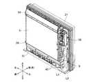
- FIG. 5 is a cross-sectional view taken along line VV shown in FIG. 3. It is a perspective view when the front panel is removed from the indoor unit. It is a figure which shows the control block of an indoor unit. It is a figure explaining operation
- the air conditioner of the present embodiment includes a compressor 1, a four-way switching valve 2 having a discharge side of the compressor 1 connected to one end, and one end at the other end of the four-way switching valve 2.
- the connected outdoor heat exchanger 3, the electric expansion valve 4 having one end connected to the other end of the outdoor heat exchanger 3, and the other end of the electric expansion valve 4 having one end via a closing valve 12 and a communication pipe L ⁇ b> 1.
- One end of the connected indoor heat exchanger 5 is connected to the other end of the indoor heat exchanger 5 via the closing valve 13, the connecting pipe L 2, and the four-way switching valve 2, and the other end is connected to the suction side of the compressor 1.
- an accumulator 6 connected thereto.
- the compressor 1, the four-way switching valve 2, the outdoor heat exchanger 3, the electric expansion valve 4, the indoor heat exchanger 5 and the accumulator 6 constitute a refrigerant circuit.
- the air conditioner also includes an outdoor fan 7 disposed in the vicinity of the outdoor heat exchanger 3 and an indoor fan 8 disposed in the vicinity of the indoor heat exchanger 5.
- the compressor 1, the four-way switching valve 2, the outdoor heat exchanger 3, the electric expansion valve 4, the accumulator 6, and the outdoor fan 7 are disposed in the outdoor unit 10, and the indoor heat exchanger 5 and the indoor fan 8 are Are arranged in the indoor unit 20.
- the high-pressure refrigerant discharged from the compressor 1 passes through the four-way switching valve 2 to the room. Enters heat exchanger 5.
- the refrigerant condensed in the indoor heat exchanger 5 enters the outdoor heat exchanger 3 after being decompressed by the electric expansion valve 4.
- the refrigerant evaporated in the outdoor heat exchanger 3 returns to the suction side of the compressor 1 through the four-way switching valve 2 and the accumulator 6.
- the refrigerant circulates through the refrigerant circuit constituted by the compressor 1, the indoor heat exchanger 5, the electric expansion valve 4, the outdoor heat exchanger 3, and the accumulator 6, and the refrigeration cycle is executed.
- the indoor fan 8 heats the room by circulating the room air through the indoor heat exchanger 5.
- the high-pressure refrigerant discharged from the compressor 1 is four-way.
- the outdoor heat exchanger 3 is entered through the switching valve 2.
- the refrigerant condensed in the outdoor heat exchanger 3 is reduced in pressure by the electric expansion valve 4 and then enters the indoor heat exchanger 5.
- the refrigerant evaporated in the indoor heat exchanger 5 returns to the suction side of the compressor 1 through the four-way switching valve 2 and the accumulator 6.
- a flammable refrigerant in this air conditioner, a flammable refrigerant is used.
- the “flammable refrigerant” includes a flammable refrigerant and a slightly flammable refrigerant.
- R32 which is a slightly flammable refrigerant is used, but R290 may be used, for example.
- a refrigerant having a specific gravity greater than that of air is used.
- the indoor unit 20 is a floor-standing indoor unit, and is attached to the front side of the bottom frame 21 and a substantially rectangular bottom frame 21 whose rear side is attached to the wall surface of the room.
- a front grille 22 having a substantially rectangular opening 22c on the front surface, and a front panel 23 attached to cover the opening 22c of the front grill 22.
- a casing 20 a is formed by the bottom frame 21, the front grille 22, and the front panel 23.
- An upper air outlet 22 a is provided in the upper part of the front grill 22, and a lower air outlet 22 b is provided in the lower part of the front grill 22.
- An upper and lower flap 24 that changes the airflow direction of the airflow blown from the upper air outlet 22a in the vertical direction is provided in the upper air outlet passage P1 that communicates with the upper air outlet 22a.
- a flap motor 24 a (see FIG. 7) is connected to the upper and lower flaps 24.
- the upper and lower flaps 24 can be rotated around a rotation axis along the horizontal direction by driving a flap motor 24a.
- the upper and lower flaps 24 rotate in the vertical air direction control range shown in FIG. 4 and blow out cold air or warm air forward and obliquely upward from the upper air outlet 22a.
- the upper air outlet 22a is closed as shown in FIG.
- a display unit 52 is provided on the upper portion of the front grill 22.
- the display unit 52 displays the operation state of the indoor unit 20, and when the operation is stopped due to leakage of refrigerant gas in the indoor unit 20, information indicating that the operation has been stopped due to an abnormality is displayed. .
- the shutter 30 that opens and closes the lower outlet 22b and the airflow direction of the airflow blown from the lower outlet 22b in the left-right direction are changed.
- Left and right flaps 31 are arranged.
- a shutter motor 30 b is connected to the shutter 30. As shown in FIG. 4, the shutter 30 rotates around a shaft 30a along the horizontal direction by driving the shutter motor 30b.
- the shutter 30 stops at the position A indicated by the alternate long and short dash line, opens the lower outlet 22b, stops at the position B indicated by the alternate long and short dashed line, and closes the lower outlet 22b.
- the left and right flaps 31 are manually adjusted in the direction of the flaps.
- an upper suction port 23a is provided on the upper side of the front panel 23
- a lower suction port 23b is provided on the lower side of the front panel 23
- lateral sides are provided on the left and right side surfaces of the front panel 23.
- a suction port 23c (only the right side is shown in FIG. 2) is provided.
- a fan motor 26 is fixed substantially at the center of the bottom frame 21.
- the indoor fan 8 to which the shaft of the fan motor 26 is connected is disposed on the bottom frame 21 so that the shaft is in the front-rear direction.
- the indoor fan 8 is a turbo fan that blows air sucked from the front side outward in the radial direction with respect to the shaft.
- the bottom frame 21 has a bell mouth 27 formed on the front side of the indoor fan 8.
- the indoor heat exchanger 5 is disposed on the front side of the bell mouth 27, and the front grill 22 is attached to the front side of the indoor heat exchanger 5.
- a front panel 23 is attached to the front side of the front grill 22.
- a filter 25 is attached to the opening 22 c of the front grill 22.
- the fan motor 26 is driven and the indoor fan 8 is rotated. Then, the room air is sucked into the indoor unit 20 from the upper suction port 23a, the lower suction port 23b, and the side suction port 23c by the rotation of the indoor fan 8, and is sucked into the indoor unit 20. After the heat is exchanged in the indoor heat exchanger 5, the air is blown out into the room from the upper outlet 22a and the lower outlet 22b. When the shutter 30 closes the lower air outlet 22b, the room air sucked into the indoor unit 20 is blown out only from the upper air outlet 22a.
- a drain pan 28 for receiving and draining condensed water from the air generated in the indoor heat exchanger 5 is disposed below the indoor heat exchanger 5.
- an electrical component box 50 is disposed on the right outside (longitudinal direction outside) and above the indoor heat exchanger 5.
- a refrigerant gas detection sensor 9 is detachably attached below the electrical component box 50. The refrigerant gas detection sensor 9 is disposed on the right outside (longitudinal direction outside) of the indoor heat exchanger 5 and the drain pan 28.
- the refrigerant gas having a specific gravity greater than that of the air flows downward and reaches the drain pan 28. Since the refrigerant gas that has reached the drain pan 28 flows from the left end side to the right end side of the drain pan 28, the refrigerant gas that has reached the drain pan 28 tends to overflow from the drain pan 28 on the refrigerant gas detection sensor 9 side in the longitudinal direction. The overflowing refrigerant gas stays at the bottom of the indoor unit 20 and leaks from the indoor unit 20 to the outside.
- a control unit 51 is housed in the electrical component box 50, and controls each component necessary for air conditioning operation and the like of the air conditioner. As shown in FIG. 7, the fan motor 26, the refrigerant gas detection sensor 9, the flap motor 24 a, the shutter motor 30 b, the compressor 1, the display unit 52, and the controller 53 are connected to the control unit 51.
- the control unit 51 controls the indoor fan 8, the upper and lower flaps 24, and the shutter 30, determines the presence or absence of refrigerant leakage based on the detection result of the refrigerant gas detected by the refrigerant gas detection sensor 9, Is detected, the compressor 1 is stopped or the display unit 52 displays that there is an abnormality.
- the controller 53 performs, for example, an operation for starting / stopping the operation of the air conditioner or an operation for canceling an abnormality when the operation is abnormally stopped due to refrigerant leakage, and the operation content is supplied to the control unit 51. Is done.
- the abnormality canceling operation for the controller 53 is an abnormality canceling operation indicating that the refrigerant gas detection sensor has been replaced, and the abnormality canceling operation is performed by the user without replacing the refrigerant gas detection sensor 9. In order to prevent this, for example, it is a special operation dedicated to a service person for an air conditioner.
- the special operation may be, for example, an operation that is not performed by the user's normal operation (for example, a long press of the operation button) or an operation that is not performed by the user's normal operation (for example, a long press of the operation button).
- An operation that can be performed after switching the screen of the controller 53 can be considered. Therefore, in the air conditioner of this embodiment, even when the operation is abnormally stopped due to refrigerant leakage, even if the breaker of the power source to which the air conditioner is connected is turned off, The operation of the compressor 1 is not started until an abnormality canceling operation for the controller 53 is performed.
- the refrigerant gas detection sensor 9 is a sensor that detects leaked refrigerant gas, and is disposed at the same height as the drain pan 28 or below the drain pan 28 as shown in FIG. Further, the drain pan 28 is disposed on the right outer side (longitudinal direction outer side) and on the back (rear side) of the drain pan 28 and the indoor heat exchanger 5.
- a semiconductor sensor, a contact combustion sensor, an electrochemical sensor, or the like is used as the refrigerant gas detection sensor.
- step S1 when the air conditioner is in operation, the presence or absence of refrigerant leakage is repeatedly determined based on the detection result of the refrigerant gas detected by the refrigerant gas detection sensor 9 (step S1). If it is determined that a refrigerant leak has been detected (S1: YES), the compressor is stopped as an abnormality (step S2), and the fact that the compressor has been stopped due to an abnormality is displayed on the display unit 52 (step S3).
- step S4 when the compressor is stopped as an abnormality, the operation of the compressor 1 is not started until the refrigerant gas detection sensor 9 is replaced. It is repeatedly determined whether or not an abnormality canceling operation has been performed (step S4). If it is determined that an abnormality canceling operation has been performed on the controller 53 (S4: YES), it is not displayed on the display unit 52 that the compressor has been stopped due to an abnormality (step S5).
- step S6 it is repeatedly determined whether or not the operation start operation has been performed on the controller 53 (step S6). If it is determined that the operation start operation has been performed (S6: YES), the operation of the compressor is started (step S7).
- the air conditioner of this embodiment has the following characteristics.
- the operation of the compressor 1 is not started until the operation for canceling the abnormality is performed after the compressor 1 is stopped by detecting the refrigerant gas by the refrigerant gas detection sensor 9. Therefore, it is possible to prevent the operation of the air conditioner from being continued in a state where the refrigerant gas detection sensor 9 has deteriorated.
- the compressor 1 when the compressor 1 is stopped by detecting the refrigerant gas by the refrigerant gas detection sensor 9, it is displayed on the display unit 52 that an abnormality has occurred. Since the operation is continued until the abnormality canceling operation is performed on 53, it is possible to notify the user that the operation of the compressor 1 is not started due to the occurrence of the abnormality.
- the abnormality canceling operation is a special operation for the controller 53. It is possible to prevent the user from performing an abnormality canceling operation without replacing the refrigerant gas detection sensor 9.
- the case where the operation of the compressor is not started after the refrigerant gas is detected by the refrigerant gas detection sensor and the compressor is stopped until the abnormality is released to the controller is described.
- the abnormality canceling operation indicating that the detection sensor has been replaced is not limited to the operation on the controller.
- the case where an abnormality has occurred when refrigerant leakage is detected is displayed on the display unit, and the display is continued until the abnormality is canceled.
- an abnormality has occurred. It may be notified by a method different from the display, or may not be notified that an abnormality has occurred.
- the abnormality canceling operation is a special operation for the controller.
- the special operation method may be changed.
- the refrigerant gas detection sensor is arranged in the indoor unit, but the present invention is not limited to this. Therefore, the refrigerant gas detection sensor may be arranged in the outdoor unit, and the effect of the present invention can be obtained in the air conditioner having the refrigerant gas detection sensor.
- the indoor unit may be an indoor unit other than the floor-standing indoor unit or a wall-mounted indoor unit.
- the present invention it is possible to prevent the operation from being continued in a state where the gas leak detection sensor is deteriorated.
Landscapes
- Engineering & Computer Science (AREA)
- Mechanical Engineering (AREA)
- General Engineering & Computer Science (AREA)
- Physics & Mathematics (AREA)
- Thermal Sciences (AREA)
- Chemical & Material Sciences (AREA)
- Combustion & Propulsion (AREA)
- Air Conditioning Control Device (AREA)
Abstract
ガス漏れ検知センサが劣化した状態で運転が継続される空気調和機を提供する。本発明の空気調和機は、圧縮機を有する室外機と、室外機に接続される室内機とを備え、可燃性冷媒が使用される空気調和機であって、冷媒ガス検出センサと、圧縮機が運転されている状態において、冷媒ガス検出センサにより冷媒ガスが検出されたときに異常が発生したとして圧縮機を停止する制御部とを備える。制御部は、冷媒ガス検出センサにより冷媒ガスが検出されたときに圧縮機を停止した後、異常を解除する操作が行われるまで、圧縮機の運転を開始しない。
Description
本発明は、可燃性冷媒が使用される空気調和機に関する。
従来から、可燃性冷媒が使用される空気調和機において、冷媒ガス検出センサが取り付けられたものが知られている。
冷媒ガス検出センサは、高濃度の冷媒に接触すると劣化することがある。したがって、冷媒ガス検出センサによってガス漏れを検知して運転を停止された後、冷媒ガス検出センサを交換しないで運転を開始すると、冷媒ガス検出センサによってガス漏れを適正に検出できない可能性がある。
そこで、本発明の目的は、冷媒ガス検出センサが劣化した状態で運転が継続されるのを防止できる空気調和機を提供することである。
第1の発明にかかる空気調和機は、圧縮機を有する室外機と前記室外機に接続される室内機とを備え、可燃性冷媒が使用される空気調和機であって、冷媒ガス検出センサと、前記圧縮機が運転されている状態において、前記冷媒ガス検出センサにより冷媒ガスが検出されたときに異常が発生したとして前記圧縮機を停止する制御手段とを備え、前記制御手段は、前記冷媒ガス検出センサにより冷媒ガスが検出されたときに前記圧縮機を停止した後、前記異常を解除する操作が行われるまで、前記圧縮機の運転を開始しないことを特徴とする。
この空気調和機では、冷媒ガス検出センサにより冷媒ガスが検出されることにより圧縮機を停止された後、異常を解除する操作が行われるまで、圧縮機の運転が開始されないので、冷媒ガス検出センサが劣化した状態で空気調和機の運転が継続されるのを防止できる。
第2の発明にかかる空気調和機は、第1の発明にかかる空気調和機において、前記異常が発生したことを報知する報知手段を備え、前記報知手段は、前記異常を解除する操作が行われるまで報知を継続することを特徴とすることを特徴とする。
この空気調和機では、冷媒ガス検出センサにより冷媒ガスが検出されることにより圧縮機を停止されると、異常が発生したことを報知され、その報知は異常が解除されるまで継続されるので、異常が発生したことにより圧縮機の運転が開始されないことをユーザに知らせることができる。
第3の発明にかかる空気調和機は、第1または第2の発明にかかる空気調和機において、空気調和機の運転についての操作を行うコントローラを備え、前記異常を解除する操作は、前記コントローラに対する特殊操作であることを特徴とする。
この空気調和機では、冷媒ガス検出センサにより冷媒ガスが検出されることにより圧縮機を停止されたときに、その異常を解除する操作がコントローラに対する特殊操作であるので、冷媒ガス検出センサが交換されないで、ユーザによって異常を解除する操作が行われるのを防止できる。
以上の説明に述べたように、本発明によれば、以下の効果が得られる。
第1の発明では、冷媒ガス検出センサにより冷媒ガスが検出されることにより圧縮機を停止された後、異常を解除する操作が行われるまで、圧縮機の運転が開始されないので、冷媒ガス検出センサが劣化した状態で空気調和機の運転が継続されるのを防止できる。
第2の発明では、冷媒ガス検出センサにより冷媒ガスが検出されることにより圧縮機を停止されると、異常が発生したことを報知され、その報知は異常が解除されるまで継続されるので、異常が発生したことにより圧縮機の運転が開始されないことをユーザに知らせることができる。
第3の発明では、冷媒ガス検出センサにより冷媒ガスが検出されることにより圧縮機を停止されたときに、その異常を解除する操作がコントローラに対する特殊操作であるので、冷媒ガス検出センサが交換されないで、ユーザによって異常を解除する操作が行われるのを防止できる。
以下、図面を参照しつつ本発明に係る空気調和機の実施の形態について説明する。
[空気調和機の全体構成]
図1に示すように、本実施形態の空気調和機は、圧縮機1と、圧縮機1の吐出側が一端に接続された四路切換弁2と、四路切換弁2の他端に一端が接続された室外熱交換器3と、室外熱交換器3の他端に一端が接続された電動膨張弁4と、電動膨張弁4の他端に閉鎖弁12、連絡配管L1を介して一端が接続された室内熱交換器5と、室内熱交換器5の他端に閉鎖弁13、連絡配管L2、四路切換弁2を介して一端が接続され、他端が圧縮機1の吸入側に接続されたアキュムレータ6とを備えている。上記の圧縮機1、四路切換弁2、室外熱交換器3、電動膨張弁4、室内熱交換器5およびアキュムレータ6で冷媒回路が構成されている。
図1に示すように、本実施形態の空気調和機は、圧縮機1と、圧縮機1の吐出側が一端に接続された四路切換弁2と、四路切換弁2の他端に一端が接続された室外熱交換器3と、室外熱交換器3の他端に一端が接続された電動膨張弁4と、電動膨張弁4の他端に閉鎖弁12、連絡配管L1を介して一端が接続された室内熱交換器5と、室内熱交換器5の他端に閉鎖弁13、連絡配管L2、四路切換弁2を介して一端が接続され、他端が圧縮機1の吸入側に接続されたアキュムレータ6とを備えている。上記の圧縮機1、四路切換弁2、室外熱交換器3、電動膨張弁4、室内熱交換器5およびアキュムレータ6で冷媒回路が構成されている。
また、この空気調和機は、室外熱交換器3の近傍に配置された室外ファン7と、室内熱交換器5の近傍に配置された室内ファン8とを備えている。上記の圧縮機1、四路切換弁2、室外熱交換器3、電動膨張弁4、アキュムレータ6、及び室外ファン7は、室外機10に配置され、室内熱交換器5、及び室内ファン8は、室内機20に配置されている。
この空気調和機では、暖房運転時、四路切換弁2を実線の切換え位置に切り換えて、圧縮機1を起動すると、圧縮機1から吐出された高圧冷媒が四路切換弁2を通って室内熱交換器5に入る。そして、室内熱交換器5で凝縮した冷媒は、電動膨張弁4で減圧された後に室外熱交換器3に入る。室外熱交換器3で蒸発した冷媒が四路切換弁2およびアキュムレータ6を介して圧縮機1の吸入側に戻る。こうして、圧縮機1、室内熱交換器5、電動膨張弁4、室外熱交換器3およびアキュムレータ6で構成された冷媒回路を冷媒が循環して、冷凍サイクルを実行する。そして、室内ファン8により室内熱交換器5を介して室内空気を循環させることにより室内を暖房する。
これに対して、冷房運転時(除湿運転時を含む)は、四路切換弁2を点線の切換え位置に切り換えて、圧縮機1を起動すると、圧縮機1から吐出された高圧冷媒が四路切換弁2を通って室外熱交換器3に入る。そして、室外熱交換器3で凝縮した冷媒は、電動膨張弁4で減圧された後に室内熱交換器5に入る。室内熱交換器5で蒸発した冷媒が四路切換弁2およびアキュムレータ6を介して圧縮機1の吸入側に戻る。こうして、圧縮機1、室外熱交換器3、電動膨張弁4、室内熱交換器5およびアキュムレータ6の順に冷媒が循環する冷凍サイクルを実行する。そして、室内ファン8により室内熱交換器5を介して室内空気を循環させることにより室内を冷房する。
この空気調和機では、可燃性冷媒が使用される。本発明において「可燃性冷媒」とは、可燃性冷媒のほか微燃性冷媒を含む。この空気調和機では、微燃性冷媒であるR32が用いられるが、例えばR290が用いられてもよい。また、この空気調和機では、空気よりも比重が大きい冷媒が使用される。
[室内機]
図2-図4に示すように、室内機20は、床置き型の室内機であって、室内の壁面に後面側が取り付けられる略長方形状の底フレーム21と、底フレーム21の前面側に取り付けられ、前面に略長方形状の開口部22cを有する前面グリル22と、前面グリル22の開口部22cを覆うように取り付けられた前面パネル23とを備えている。この底フレーム21、前面グリル22、及び前面パネル23により、ケーシング20aが形成されている。
図2-図4に示すように、室内機20は、床置き型の室内機であって、室内の壁面に後面側が取り付けられる略長方形状の底フレーム21と、底フレーム21の前面側に取り付けられ、前面に略長方形状の開口部22cを有する前面グリル22と、前面グリル22の開口部22cを覆うように取り付けられた前面パネル23とを備えている。この底フレーム21、前面グリル22、及び前面パネル23により、ケーシング20aが形成されている。
前面グリル22の上部には、上側吹出口22aが設けられ、前面グリル22の下部には、下側吹出口22bが設けられている。上側吹出口22aに連通する上側吹き出し通路P1には、上下方向について上側吹出口22aから吹き出される空気流の風向を変更する上下フラップ24が設けられている。上下フラップ24には、フラップモータ24a(図7参照)が接続されている。上下フラップ24は、フラップモータ24aの駆動により、水平方向に沿った回転軸の周りを回動可能である。この上下フラップ24は、冷房運転および暖房運転時には、図4に示す上下風向制御範囲において回動して、上側吹出口22aから冷風または温風を前方かつ斜め上方に吹き出す。また、運転停止時は、図2に示すように、上側吹出口22aを閉じる。
また、前面グリル22の上部には、表示部52が設けられている。表示部52には、室内機20の運転状態が表示されるとともに、室内機20において冷媒ガスが漏れて運転が停止されたときは、異常によって運転が停止されたことを示す情報が表示される。
一方、下側吹出口22bに連通する下側吹き出し通路P2内には、下側吹出口22bを開閉するシャッター30と、左右方向について下側吹出口22bから吹き出される空気流の風向を変更する左右フラップ31が配置されている。シャッター30には、シャッターモータ30bが接続されている。シャッター30は、シャッターモータ30bの駆動により、図4に示すように、水平方向に沿った軸30aを中心に回動する。このシャッター30は、一点鎖線で示すAの位置で停止して、下側吹出口22bを開き、一点鎖線で示すBの位置で停止して、下側吹出口22bを閉じる。なお、左右フラップ31は、手動でフラップの向きが調整されるものである。
また、上記前面パネル23の上側には、上側吸込口23aが設けられ、前面パネル23の下側には、下側吸込口23bが設けられ、さらに前面パネル23の左右の側面には、側方吸込口23c(図2では右側のみを示す)が設けられている。
図4に示すように、底フレーム21の略中央には、ファンモータ26が固定されている。このファンモータ26の軸が接続された室内ファン8が、軸が前後方向になるように底フレーム21に配置されている。室内ファン8は、前面側から吸い込んだ空気を軸に対して半径方向外側に吹き出すターボファンである。また、底フレーム21は、室内ファン8の前面側に形成されたベルマウス27を有している。そして、ベルマウス27の前面側に室内熱交換器5が配置され、その室内熱交換器5の前面側に前面グリル22が取り付けられる。また、その前面グリル22のさらに前面側に前面パネル23が取り付けられる。前面グリル22の開口部22cには、フィルタ25が取り付けられている。
この空気調和機では、運転が開始されると、ファンモータ26が駆動して、室内ファン8が回転する。そして、室内ファン8の回転によって、上側吸込口23a、下側吸込口23b、及び側方吸込口23cから室内機20の内部に室内空気が吸い込まれて、室内機20の内部に吸い込まれた室内空気は、室内熱交換器5で熱交換された後、上側吹出口22aおよび下側吹出口22bからが室内に吹き出される。なお、シャッター30が、下側吹出口22bを閉じている場合には、室内機20の内部に吸い込まれた室内空気は、上側吹出口22aのみから吹き出される。
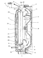
図5、図6に示すように、室内熱交換器5の下方には、室内熱交換器5で生じた空気中からの凝縮水を受け取って排水するためのドレンパン28が配置されている。また、室内熱交換器5の右外側(長手方向外側)、かつ上方には、電装品箱50が配置されている。電装品箱50の下方には、冷媒ガス検出センサ9が着脱可能に取り付けられている。この冷媒ガス検出センサ9は、室内熱交換器5及びドレンパン28の右外側(長手方向外側)に配置される。
この空気調和機では、万一、室内熱交換器5内の冷媒配管が破損するなどして、冷媒ガスが漏洩した場合、空気より比重の大きい冷媒ガスは下方に流れて、ドレンパン28に達する。ドレンパン28に達した冷媒ガスは、ドレンパン28の左端側から右端側に向かって流れるため、ドレンパン28に達した冷媒ガスは、長手方向について冷媒ガス検出センサ9側において、ドレンパン28から溢れやすい。溢れた冷媒ガスは、室内機20の底に滞留し、室内機20から外部に漏洩する。
(電装品箱)
電装品箱50には、制御部51が収納されており、空気調和機の冷暖房運転等に必要な各構成部品の制御を行う。この制御部51には、図7に示すように、ファンモータ26、冷媒ガス検出センサ9、フラップモータ24a、シャッターモータ30b、圧縮機1、表示部52、コントローラ53が接続されている。制御部51は、室内ファン8、上下フラップ24、シャッター30の制御を行ったり、冷媒ガス検出センサ9で検出された冷媒ガスの検出結果に基づいて、冷媒漏れの有無を判断したり、冷媒漏れが検出されたときに、圧縮機1を停止したり、異常があったことを表示部52に表示する。コントローラ53は、例えば、空気調和機の運転の開始操作・停止操作や、冷媒漏れにより運転が異常停止されたときの異常解除操作を行うものであって、その操作内容は、制御部51に供給される。本実施形態において、コントローラ53に対する異常解除操作は、冷媒ガス検出センサが交換されたことを示す異常解除操作であって、冷媒ガス検出センサ9が交換されないで、ユーザによって異常解除操作が行われるのを防止するため、例えば、空気調和機についてのサービスマン専用の特殊操作である。特殊操作としては、例えば、ユーザの通常操作では行われない操作(例えば、操作ボタンの長押し)であってよいし、ユーザの通常操作では行われない操作(例えば、操作ボタンの長押し)によって、コントローラ53の画面を切り換えた後で可能となる操作が考えられる。したがって、本実施形態の空気調和機では、冷媒漏れにより運転が異常停止されたときに、仮に、空気調和機が接続された電源のブレーカをオフ状態にした後、オン状態に切り換えたとしても、コントローラ53に対する異常解除操作が行われるまでは、圧縮機1の運転は開始されない。
電装品箱50には、制御部51が収納されており、空気調和機の冷暖房運転等に必要な各構成部品の制御を行う。この制御部51には、図7に示すように、ファンモータ26、冷媒ガス検出センサ9、フラップモータ24a、シャッターモータ30b、圧縮機1、表示部52、コントローラ53が接続されている。制御部51は、室内ファン8、上下フラップ24、シャッター30の制御を行ったり、冷媒ガス検出センサ9で検出された冷媒ガスの検出結果に基づいて、冷媒漏れの有無を判断したり、冷媒漏れが検出されたときに、圧縮機1を停止したり、異常があったことを表示部52に表示する。コントローラ53は、例えば、空気調和機の運転の開始操作・停止操作や、冷媒漏れにより運転が異常停止されたときの異常解除操作を行うものであって、その操作内容は、制御部51に供給される。本実施形態において、コントローラ53に対する異常解除操作は、冷媒ガス検出センサが交換されたことを示す異常解除操作であって、冷媒ガス検出センサ9が交換されないで、ユーザによって異常解除操作が行われるのを防止するため、例えば、空気調和機についてのサービスマン専用の特殊操作である。特殊操作としては、例えば、ユーザの通常操作では行われない操作(例えば、操作ボタンの長押し)であってよいし、ユーザの通常操作では行われない操作(例えば、操作ボタンの長押し)によって、コントローラ53の画面を切り換えた後で可能となる操作が考えられる。したがって、本実施形態の空気調和機では、冷媒漏れにより運転が異常停止されたときに、仮に、空気調和機が接続された電源のブレーカをオフ状態にした後、オン状態に切り換えたとしても、コントローラ53に対する異常解除操作が行われるまでは、圧縮機1の運転は開始されない。
(冷媒ガス検出センサ)
冷媒ガス検出センサ9は、漏洩した冷媒ガスを検出するセンサであり、図5に示すように、ドレンパン28と同じ高さ又はドレンパン28より下方に配置されている。また、ドレンパン28の右外側(長手方向外側)かつドレンパン28及び室内熱交換器5よりも奥(後方)に配置されている。冷媒ガス検出センサとして、半導体センサ、接触燃焼式センサ、電気化学式センサなどが使用される。
冷媒ガス検出センサ9は、漏洩した冷媒ガスを検出するセンサであり、図5に示すように、ドレンパン28と同じ高さ又はドレンパン28より下方に配置されている。また、ドレンパン28の右外側(長手方向外側)かつドレンパン28及び室内熱交換器5よりも奥(後方)に配置されている。冷媒ガス検出センサとして、半導体センサ、接触燃焼式センサ、電気化学式センサなどが使用される。
本実施形態の空気調和機において冷媒ガスの漏れが検出されたときの動作について、図8に基づいて説明する。
まず、空気調和機が運転されているときに、冷媒ガス検出センサ9で検出された冷媒ガスの検出結果に基づいて、冷媒漏れの有無が繰り返し判断される(ステップS1)。冷媒漏れが検出されたと判断されると(S1:YES)、異常として圧縮機が停止され(ステップS2)、異常により圧縮機が停止されたことが表示部52に表示される(ステップS3)。
本発明の空気調和機では、異常として圧縮機が停止されたとき、冷媒ガス検出センサ9が交換されるまでは、圧縮機1の運転を開始しないように構成されているので、コントローラ53に対し異常解除操作が行われたか否かが繰り返し判断される(ステップS4)。コントローラ53に対し異常解除操作が行われたと判断されると(S4:YES)、表示部52において異常により圧縮機が停止されたことが表示されなくなる(ステップS5)。
その後、コントローラ53に対し運転開始操作が行われたか否かが繰り返し判断される(ステップS6)。運転開始操作が行われたと判断されると(S6:YES)、圧縮機の運転が開始される(ステップS7)。
[本実施形態の空気調和機の特徴]
本実施形態の空気調和機には、以下の特徴がある。
本実施形態の空気調和機には、以下の特徴がある。
本実施形態の空気調和機では、冷媒ガス検出センサ9により冷媒ガスが検出されることにより圧縮機1を停止された後、異常を解除する操作が行われるまで、圧縮機1の運転が開始されないので、冷媒ガス検出センサ9が劣化した状態で空気調和機の運転が継続されるのを防止できる。
本実施形態の空気調和機では、冷媒ガス検出センサ9により冷媒ガスが検出されることにより圧縮機1を停止されると、異常が発生したことが表示部52に表示され、その表示は、コントローラ53に対し異常解除操作が行われるまで継続されるので、異常が発生したことにより圧縮機1の運転が開始されないことをユーザに知らせることができる。
本実施形態の空気調和機の室内機では、冷媒ガス検出センサ9により冷媒ガスが検出されることにより圧縮機1を停止されたきに、その異常の解除操作はコントローラ53に対する特殊操作であるので、冷媒ガス検出センサ9が交換されないで、ユーザによって異常の解除操作が行われるのを防止できる。
以上、本発明の実施形態について図面に基づいて説明したが、具体的な構成は、これらの実施形態に限定されるものでないと考えられるべきである。本発明の範囲は、上記した実施形態の説明ではなく特許請求の範囲によって示され、さらに特許請求の範囲と均等の意味及び範囲内でのすべての変更が含まれる。
上記実施形態では、冷媒ガス検出センサにより冷媒ガスが検出されて圧縮機が停止された後、コントローラに対し異常解除操作が行われるまで、圧縮機の運転を開始しない場合を説明したが、冷媒ガス検出センサが交換されたことを示す異常解除操作は、コントローラに対する操作に限らない。
上記実施形態では、冷媒漏れが検出されたときに異常が発生したことが表示部に表示され、その表示が、異常が解除されるまで継続される場合を説明したが、異常が発生したことが表示と異なる方法によって報知されるものであってよいし、異常が発生したことが報知されないものであってよい。
上記実施形態では、異常解除操作がコントローラに対する特殊操作である場合を説明したが、特殊操作の方法は変更してよい。
上記実施形態では、冷媒ガス検出センサが室内機に配置される場合を説明したが、それに限られない。したがって、冷媒ガス検出センサが室外機に配置されたものであってよいし、冷媒ガス検出センサを有する空気調和機において、本発明の効果が得られる。上記実施形態では、室内機が床置き型の室内機である場合を説明したが、室内機は床置き型以外の室内機であってよいし、壁掛けの室内機であってよい。
本発明を利用すれば、ガス漏れ検知センサが劣化した状態で運転が継続されるのを防止できる。
1 圧縮機
9 冷媒ガス検出センサ
10 室外機
20 室内機
51 制御部(制御手段)
52 表示部(報知手段)
53 コントローラ
9 冷媒ガス検出センサ
10 室外機
20 室内機
51 制御部(制御手段)
52 表示部(報知手段)
53 コントローラ
Claims (3)
- 圧縮機を有する室外機と前記室外機に接続される室内機とを備え、可燃性冷媒が使用される空気調和機であって、
冷媒ガス検出センサと、
前記圧縮機が運転されている状態において、前記冷媒ガス検出センサにより冷媒ガスが検出されたときに異常が発生したとして前記圧縮機を停止する制御手段とを備え、
前記制御手段は、前記冷媒ガス検出センサにより冷媒ガスが検出されたときに前記圧縮機を停止した後、前記異常を解除する操作が行われるまで、前記圧縮機の運転を開始しないことを特徴とする空気調和機。 - 前記異常が発生したことを報知する報知手段を備え、
前記報知手段は、前記異常を解除する操作が行われるまで報知を継続することを特徴とする請求項1に記載の空気調和機。 - 空気調和機の運転についての操作を行うコントローラを備え、
前記異常を解除する操作は、前記コントローラに対する特殊操作であることを特徴とする請求項1または2に記載の空気調和機。
Priority Applications (5)
| Application Number | Priority Date | Filing Date | Title |
|---|---|---|---|
| ES15855188T ES2773695T3 (es) | 2014-10-31 | 2015-09-29 | Acondicionador de aire |
| AU2015338330A AU2015338330B2 (en) | 2014-10-31 | 2015-09-29 | Air conditioner |
| EP15855188.7A EP3249311B1 (en) | 2014-10-31 | 2015-09-29 | Air conditioner |
| US15/522,894 US11248816B2 (en) | 2014-10-31 | 2015-09-29 | Air conditioner |
| CN201580058212.8A CN107110541B (zh) | 2014-10-31 | 2015-09-29 | 空调机 |
Applications Claiming Priority (2)
| Application Number | Priority Date | Filing Date | Title |
|---|---|---|---|
| JP2014-223397 | 2014-10-31 | ||
| JP2014223397A JP6020534B2 (ja) | 2014-10-31 | 2014-10-31 | 空気調和機 |
Publications (1)
| Publication Number | Publication Date |
|---|---|
| WO2016067815A1 true WO2016067815A1 (ja) | 2016-05-06 |
Family
ID=55857161
Family Applications (1)
| Application Number | Title | Priority Date | Filing Date |
|---|---|---|---|
| PCT/JP2015/077564 Ceased WO2016067815A1 (ja) | 2014-10-31 | 2015-09-29 | 空気調和機 |
Country Status (7)
| Country | Link |
|---|---|
| US (1) | US11248816B2 (ja) |
| EP (1) | EP3249311B1 (ja) |
| JP (1) | JP6020534B2 (ja) |
| CN (1) | CN107110541B (ja) |
| AU (1) | AU2015338330B2 (ja) |
| ES (1) | ES2773695T3 (ja) |
| WO (1) | WO2016067815A1 (ja) |
Families Citing this family (16)
| Publication number | Priority date | Publication date | Assignee | Title |
|---|---|---|---|---|
| US10119738B2 (en) | 2014-09-26 | 2018-11-06 | Waterfurnace International Inc. | Air conditioning system with vapor injection compressor |
| JPWO2016157538A1 (ja) * | 2015-04-03 | 2017-04-27 | 三菱電機株式会社 | 冷凍サイクル装置 |
| US10871314B2 (en) | 2016-07-08 | 2020-12-22 | Climate Master, Inc. | Heat pump and water heater |
| US10866002B2 (en) | 2016-11-09 | 2020-12-15 | Climate Master, Inc. | Hybrid heat pump with improved dehumidification |
| JP6875423B2 (ja) * | 2017-01-19 | 2021-05-26 | 三菱電機株式会社 | 冷凍サイクル装置 |
| JP6929747B2 (ja) * | 2017-09-25 | 2021-09-01 | 東芝キヤリア株式会社 | 空気調和機 |
| JP7085405B2 (ja) * | 2018-05-15 | 2022-06-16 | 三菱重工サーマルシステムズ株式会社 | 熱源システム、制御装置、熱源システム運転方法及びプログラム |
| WO2020014279A1 (en) * | 2018-07-09 | 2020-01-16 | Crane Payment Innovations, Inc. | Refrigerant leak detector for a vending machine |
| US11592215B2 (en) | 2018-08-29 | 2023-02-28 | Waterfurnace International, Inc. | Integrated demand water heating using a capacity modulated heat pump with desuperheater |
| CA3081986A1 (en) | 2019-07-15 | 2021-01-15 | Climate Master, Inc. | Air conditioning system with capacity control and controlled hot water generation |
| US11231198B2 (en) | 2019-09-05 | 2022-01-25 | Trane International Inc. | Systems and methods for refrigerant leak detection in a climate control system |
| JP7436784B2 (ja) * | 2019-09-30 | 2024-02-22 | ダイキン工業株式会社 | 空気調和機 |
| US11512867B2 (en) | 2020-03-12 | 2022-11-29 | Johnson Controls Tyco IP Holdings LLP | Refrigerant detection and control of HVAC system |
| US12181189B2 (en) | 2021-11-10 | 2024-12-31 | Climate Master, Inc. | Ceiling-mountable heat pump system |
| US12487008B2 (en) | 2022-01-14 | 2025-12-02 | Trane International Inc. | Method of commissioning an HVAC system |
| US12117191B2 (en) | 2022-06-24 | 2024-10-15 | Trane International Inc. | Climate control system with improved leak detector |
Citations (3)
| Publication number | Priority date | Publication date | Assignee | Title |
|---|---|---|---|---|
| JPH06180166A (ja) * | 1992-12-09 | 1994-06-28 | Toshiba Corp | 空気調和機 |
| JP2000356387A (ja) * | 1999-06-11 | 2000-12-26 | Corona Corp | 空気調和機の制御装置 |
| JP2011117655A (ja) * | 2009-12-02 | 2011-06-16 | Toshiba Carrier Corp | 空気調和機 |
Family Cites Families (11)
| Publication number | Priority date | Publication date | Assignee | Title |
|---|---|---|---|---|
| US3412570A (en) * | 1965-05-24 | 1968-11-26 | George H. Pruett Sr. | Radiation sensitive system for detecting refrigerant leaks |
| US4787212A (en) * | 1987-10-19 | 1988-11-29 | Hessey John C | Air conditioner with automatic shutdown |
| DE3990187C2 (de) * | 1988-02-24 | 1993-11-25 | Matsushita Electric Works Ltd | Elektrochemischer Gassensor |
| JP2523191B2 (ja) * | 1989-09-01 | 1996-08-07 | 富士機械製造株式会社 | シ―ケンス制御装置 |
| JPH11230648A (ja) * | 1998-02-13 | 1999-08-27 | Matsushita Electric Ind Co Ltd | 可燃性冷媒を用いた冷凍機器の冷媒漏洩警報装置 |
| US6085530A (en) * | 1998-12-07 | 2000-07-11 | Scroll Technologies | Discharge temperature sensor for sealed compressor |
| US6907748B2 (en) * | 2003-02-28 | 2005-06-21 | Delphi Technologies, Inc. | HVAC system with refrigerant venting |
| WO2010062923A1 (en) * | 2008-11-26 | 2010-06-03 | Delphi Technologies, Inc. | Refrigerant leak detection system |
| JP2012013348A (ja) | 2010-07-02 | 2012-01-19 | Panasonic Corp | 空気調和機 |
| JP5968629B2 (ja) | 2012-01-25 | 2016-08-10 | 株式会社クボタ | サイロおよびサイロの運転方法 |
| JP5812081B2 (ja) * | 2013-11-12 | 2015-11-11 | ダイキン工業株式会社 | 室内機 |
-
2014
- 2014-10-31 JP JP2014223397A patent/JP6020534B2/ja active Active
-
2015
- 2015-09-29 CN CN201580058212.8A patent/CN107110541B/zh active Active
- 2015-09-29 ES ES15855188T patent/ES2773695T3/es active Active
- 2015-09-29 AU AU2015338330A patent/AU2015338330B2/en active Active
- 2015-09-29 WO PCT/JP2015/077564 patent/WO2016067815A1/ja not_active Ceased
- 2015-09-29 US US15/522,894 patent/US11248816B2/en active Active
- 2015-09-29 EP EP15855188.7A patent/EP3249311B1/en active Active
Patent Citations (3)
| Publication number | Priority date | Publication date | Assignee | Title |
|---|---|---|---|---|
| JPH06180166A (ja) * | 1992-12-09 | 1994-06-28 | Toshiba Corp | 空気調和機 |
| JP2000356387A (ja) * | 1999-06-11 | 2000-12-26 | Corona Corp | 空気調和機の制御装置 |
| JP2011117655A (ja) * | 2009-12-02 | 2011-06-16 | Toshiba Carrier Corp | 空気調和機 |
Non-Patent Citations (1)
| Title |
|---|
| See also references of EP3249311A4 * |
Also Published As
| Publication number | Publication date |
|---|---|
| US11248816B2 (en) | 2022-02-15 |
| JP2016090111A (ja) | 2016-05-23 |
| JP6020534B2 (ja) | 2016-11-02 |
| US20170328620A1 (en) | 2017-11-16 |
| CN107110541A (zh) | 2017-08-29 |
| EP3249311B1 (en) | 2019-12-04 |
| CN107110541B (zh) | 2018-08-07 |
| EP3249311A1 (en) | 2017-11-29 |
| EP3249311A4 (en) | 2018-11-07 |
| ES2773695T3 (es) | 2020-07-14 |
| AU2015338330B2 (en) | 2017-06-22 |
Similar Documents
| Publication | Publication Date | Title |
|---|---|---|
| JP6020534B2 (ja) | 空気調和機 | |
| US10126012B2 (en) | Air conditioner | |
| JP5804027B2 (ja) | 空気調和機の室内機 | |
| JP6248898B2 (ja) | 空気調和機 | |
| CN107003052B (zh) | 空调机 | |
| JP5983707B2 (ja) | 空気調和機の室内機 | |
| JP5987887B2 (ja) | 空気調和機の室内機 | |
| JP5892199B2 (ja) | 空調室内機 | |
| JP2016125694A (ja) | 空気調和装置の室内機 | |
| ES2806647T3 (es) | Acondicionador de aire | |
| JP2015094512A (ja) | 床置型空気調和機の室内機 | |
| JP4209912B2 (ja) | 空気調和機 | |
| JP6914794B2 (ja) | 空気調和機 | |
| JPWO2017037841A1 (ja) | 冷凍サイクル装置及びその設置方法 | |
| JP2016090112A (ja) | 空気調和機 |
Legal Events
| Date | Code | Title | Description |
|---|---|---|---|
| 121 | Ep: the epo has been informed by wipo that ep was designated in this application |
Ref document number: 15855188 Country of ref document: EP Kind code of ref document: A1 |
|
| WWE | Wipo information: entry into national phase |
Ref document number: 15522894 Country of ref document: US |
|
| NENP | Non-entry into the national phase |
Ref country code: DE |
|
| REEP | Request for entry into the european phase |
Ref document number: 2015855188 Country of ref document: EP |
|
| WWE | Wipo information: entry into national phase |
Ref document number: 2015338330 Country of ref document: AU |