WO2016067840A1 - 画像形成装置 - Google Patents
画像形成装置 Download PDFInfo
- Publication number
- WO2016067840A1 WO2016067840A1 PCT/JP2015/078230 JP2015078230W WO2016067840A1 WO 2016067840 A1 WO2016067840 A1 WO 2016067840A1 JP 2015078230 W JP2015078230 W JP 2015078230W WO 2016067840 A1 WO2016067840 A1 WO 2016067840A1
- Authority
- WO
- WIPO (PCT)
- Prior art keywords
- transfer
- forming apparatus
- image forming
- image
- power supply
- Prior art date
- Legal status (The legal status is an assumption and is not a legal conclusion. Google has not performed a legal analysis and makes no representation as to the accuracy of the status listed.)
- Ceased
Links
Images



Classifications
-
- G—PHYSICS
- G03—PHOTOGRAPHY; CINEMATOGRAPHY; ANALOGOUS TECHNIQUES USING WAVES OTHER THAN OPTICAL WAVES; ELECTROGRAPHY; HOLOGRAPHY
- G03G—ELECTROGRAPHY; ELECTROPHOTOGRAPHY; MAGNETOGRAPHY
- G03G21/00—Arrangements not provided for by groups G03G13/00 - G03G19/00, e.g. cleaning, elimination of residual charge
- G03G21/06—Eliminating residual charges from a reusable imaging member
- G03G21/08—Eliminating residual charges from a reusable imaging member using optical radiation
-
- G—PHYSICS
- G03—PHOTOGRAPHY; CINEMATOGRAPHY; ANALOGOUS TECHNIQUES USING WAVES OTHER THAN OPTICAL WAVES; ELECTROGRAPHY; HOLOGRAPHY
- G03G—ELECTROGRAPHY; ELECTROPHOTOGRAPHY; MAGNETOGRAPHY
- G03G15/00—Apparatus for electrographic processes using a charge pattern
- G03G15/80—Details relating to power supplies, circuits boards, electrical connections
-
- G—PHYSICS
- G03—PHOTOGRAPHY; CINEMATOGRAPHY; ANALOGOUS TECHNIQUES USING WAVES OTHER THAN OPTICAL WAVES; ELECTROGRAPHY; HOLOGRAPHY
- G03G—ELECTROGRAPHY; ELECTROPHOTOGRAPHY; MAGNETOGRAPHY
- G03G15/00—Apparatus for electrographic processes using a charge pattern
- G03G15/01—Apparatus for electrographic processes using a charge pattern for producing multicoloured copies
- G03G15/0105—Details of unit
- G03G15/0131—Details of unit for transferring a pattern to a second base
-
- G—PHYSICS
- G03—PHOTOGRAPHY; CINEMATOGRAPHY; ANALOGOUS TECHNIQUES USING WAVES OTHER THAN OPTICAL WAVES; ELECTROGRAPHY; HOLOGRAPHY
- G03G—ELECTROGRAPHY; ELECTROPHOTOGRAPHY; MAGNETOGRAPHY
- G03G15/00—Apparatus for electrographic processes using a charge pattern
- G03G15/14—Apparatus for electrographic processes using a charge pattern for transferring a pattern to a second base
- G03G15/16—Apparatus for electrographic processes using a charge pattern for transferring a pattern to a second base of a toner pattern, e.g. a powder pattern, e.g. magnetic transfer
-
- G—PHYSICS
- G03—PHOTOGRAPHY; CINEMATOGRAPHY; ANALOGOUS TECHNIQUES USING WAVES OTHER THAN OPTICAL WAVES; ELECTROGRAPHY; HOLOGRAPHY
- G03G—ELECTROGRAPHY; ELECTROPHOTOGRAPHY; MAGNETOGRAPHY
- G03G15/00—Apparatus for electrographic processes using a charge pattern
- G03G15/14—Apparatus for electrographic processes using a charge pattern for transferring a pattern to a second base
- G03G15/16—Apparatus for electrographic processes using a charge pattern for transferring a pattern to a second base of a toner pattern, e.g. a powder pattern, e.g. magnetic transfer
- G03G15/1605—Apparatus for electrographic processes using a charge pattern for transferring a pattern to a second base of a toner pattern, e.g. a powder pattern, e.g. magnetic transfer using at least one intermediate support
-
- G—PHYSICS
- G03—PHOTOGRAPHY; CINEMATOGRAPHY; ANALOGOUS TECHNIQUES USING WAVES OTHER THAN OPTICAL WAVES; ELECTROGRAPHY; HOLOGRAPHY
- G03G—ELECTROGRAPHY; ELECTROPHOTOGRAPHY; MAGNETOGRAPHY
- G03G15/00—Apparatus for electrographic processes using a charge pattern
- G03G15/14—Apparatus for electrographic processes using a charge pattern for transferring a pattern to a second base
- G03G15/16—Apparatus for electrographic processes using a charge pattern for transferring a pattern to a second base of a toner pattern, e.g. a powder pattern, e.g. magnetic transfer
- G03G15/1625—Apparatus for electrographic processes using a charge pattern for transferring a pattern to a second base of a toner pattern, e.g. a powder pattern, e.g. magnetic transfer on a base other than paper
-
- G—PHYSICS
- G03—PHOTOGRAPHY; CINEMATOGRAPHY; ANALOGOUS TECHNIQUES USING WAVES OTHER THAN OPTICAL WAVES; ELECTROGRAPHY; HOLOGRAPHY
- G03G—ELECTROGRAPHY; ELECTROPHOTOGRAPHY; MAGNETOGRAPHY
- G03G15/00—Apparatus for electrographic processes using a charge pattern
- G03G15/14—Apparatus for electrographic processes using a charge pattern for transferring a pattern to a second base
- G03G15/16—Apparatus for electrographic processes using a charge pattern for transferring a pattern to a second base of a toner pattern, e.g. a powder pattern, e.g. magnetic transfer
- G03G15/1665—Apparatus for electrographic processes using a charge pattern for transferring a pattern to a second base of a toner pattern, e.g. a powder pattern, e.g. magnetic transfer by introducing the second base in the nip formed by the recording member and at least one transfer member, e.g. in combination with bias or heat
- G03G15/167—Apparatus for electrographic processes using a charge pattern for transferring a pattern to a second base of a toner pattern, e.g. a powder pattern, e.g. magnetic transfer by introducing the second base in the nip formed by the recording member and at least one transfer member, e.g. in combination with bias or heat at least one of the recording member or the transfer member being rotatable during the transfer
- G03G15/1675—Apparatus for electrographic processes using a charge pattern for transferring a pattern to a second base of a toner pattern, e.g. a powder pattern, e.g. magnetic transfer by introducing the second base in the nip formed by the recording member and at least one transfer member, e.g. in combination with bias or heat at least one of the recording member or the transfer member being rotatable during the transfer with means for controlling the bias applied in the transfer nip
Definitions
- the present invention relates to an image forming apparatus.
- a color image forming apparatus such as an electrophotographic color copying machine, a color printing machine, or a color composite machine is known.
- an electrophotographic color image forming apparatus an intermediate transfer belt type color image forming apparatus and a direct transfer belt type color image forming apparatus are known.
- the intermediate transfer belt type color image forming apparatus and the direct transfer belt type color image forming apparatus carry, for example, yellow (Y), cyan (C), magenta (M), and black (Bk) toner images, respectively.
- Y yellow
- C cyan
- M magenta
- Bk black
- Four photosensitive drums are provided.
- the four photosensitive drums are arranged in tandem along the circumferential direction (traveling direction) of the endless belt. For this reason, an intermediate transfer belt type color image forming apparatus and a direct transfer belt type color image forming apparatus are sometimes referred to as tandem type image forming apparatuses.
- the tandem type image forming apparatus applies a potential to each photosensitive drum, and causes each photosensitive drum to carry a toner image of each color by electrostatic force.
- an intermediate transfer belt type color image forming apparatus toner images of respective colors are sequentially transferred onto an intermediate transfer belt that is a transfer target. As a result, a color toner image is formed on the intermediate transfer belt. Then, the color toner image on the intermediate transfer belt is transferred to a recording medium such as paper.
- the toner images of the respective colors carried on the respective photosensitive drums are sequentially transferred in a superimposed manner on a recording medium (transferred body) conveyed by the belt.
- the tandem-type image forming apparatus applies a potential to each transfer roller (transfer member) disposed to face each photoconductor drum when transferring the toner image of each color from each photoconductor drum to the transfer target.
- the toner image of each color is transferred from each photosensitive drum to the transfer target due to a potential difference (transfer electric field) between each photosensitive drum and each corresponding transfer roller.
- each photoconductive drum is discharged by, for example, irradiating each photoconductive drum with discharge light.
- the DC charging roller system such as the plus DC charging roller system has a lower ability to charge the photoconductor than the scorotron system. For this reason, the electric charge applied to the surface of the photoconductor by the transfer electric field is not completely canceled in the next charging step and tends to remain on the surface of the photoconductor. That is, the surface of the photoconductor is not uniformly charged, and a potential difference derived from the previously transferred toner image (image) is likely to occur. In other words, the history of the previously transferred toner image (image) tends to remain on the photoconductor.
- the DC charging roller system easily generates a phenomenon in which a toner image (image) transferred last time is thinly transferred to a transfer target in the next transfer process, that is, a so-called transfer memory (drum ghost).
- a method for solving this problem there is known a method of irradiating the photosensitive drum before transferring the toner image, in other words, irradiating the photosensitive drum carrying the toner image with static elimination light (for example, see Patent Document 1.)
- the image forming apparatus described in Patent Document 1 is positioned upstream and downstream with respect to the belt traveling direction (moving direction of the transfer medium) by one neutralization substrate disposed between adjacent photosensitive drums. Each photosensitive drum is irradiated with static elimination light. As a result, it is possible to irradiate the downstream photoconductor drum with the neutralizing light after the transfer of the toner image, and irradiate the upstream photoconductor drum with the neutralizing light before the transfer of the toner image. be able to.
- the charge removal after transfer of the toner image may be referred to as post-transfer charge removal
- the charge removal before transfer of the toner image may be referred to as pre-transfer charge removal.
- the charge removal before transfer reduces the potential difference between the image portion (portion carrying the toner image) and the non-image portion (portion carrying no toner image) on the surface of the photosensitive drum.
- pre-transfer charge removal and post-transfer charge removal are performed by a single charge removal substrate, pre-transfer slow charge cannot be performed on the photosensitive drum located on the most upstream side with respect to the belt traveling direction.
- the surface potential of the photosensitive drum located on the most upstream side is higher than the surface potential of the other photosensitive drums. There may be.
- a high-voltage power source is provided for each transfer roller (transfer member) to keep a current flowing into each photosensitive drum constant.
- an object of the present invention is to provide an image forming apparatus capable of reducing the number of necessary power supplies while suppressing deterioration in image quality.
- the image forming apparatus is an image forming apparatus capable of forming a color image by superimposing and transferring toner images of respective colors.
- the image forming apparatus includes a plurality of image carriers, a plurality of transfer members, and a power supply unit.
- the plurality of image carriers can carry the toner images of different colors.
- the plurality of transfer members face each of the plurality of image carriers.
- the power supply unit can transfer the toner images carried by the plurality of image carriers to a moving transfer target by charging the plurality of transfer members.
- the power supply unit includes a first power supply device connected to at least two of the plurality of transfer members. Among the plurality of transfer members, each of the transfer members connected to the first power supply device is shifted to the upstream side or the downstream side with respect to the moving direction of the transfer target body relative to the corresponding image carrier. Arranged.
- FIG. 1 is a longitudinal sectional view of an image forming apparatus according to an embodiment of the present invention.
- 2 is an enlarged longitudinal sectional view showing an image forming unit and a transfer unit according to an embodiment of the present invention. It is a figure which shows the power supply system with respect to the primary transfer roller which concerns on embodiment of this invention. It is a figure which shows the other example of the power supply system with respect to the primary transfer roller which concerns on embodiment of this invention. It is a figure which shows the result of Examples 1-3 of this invention, and Comparative Examples 1 and 2.
- FIG. It is a figure which shows the result of Example 3 and 4 of this invention. It is a figure which shows the result of the comparative examples 1 and 3.
- FIG. 1 is a longitudinal sectional view of an image forming apparatus according to the present embodiment.
- the image forming apparatus 1 is an intermediate transfer belt type color image forming apparatus.
- the image forming apparatus 1 can form a color image (color toner image) by transferring toner images of each color of yellow (Y), cyan (C), magenta (M), and black (Bk) in an overlapping manner. It is.
- the image forming apparatus 1 includes a housing 2, an image forming unit 3, an exposure device 4, a transfer unit 5, a paper feed cassette 6, a paper feed unit 7, a first sheet transport unit 8, a fixing unit 9, a discharge tray 10, and a manual feed tray. 11, a paper feed roller 12, a second sheet conveyance unit 13, a third sheet conveyance unit 14, and a toner supply unit 15.
- the image forming unit 3 includes four photosensitive drums 31 (image carrier) provided corresponding to each color of yellow, cyan, magenta, and black. Each photoconductor drum 31 can carry toner images of different colors. The diameter ⁇ of each photosensitive drum 31 is, for example, 30 mm. The image forming unit 3 can form yellow, cyan, magenta, and black toner images on the peripheral surfaces of the four photosensitive drums 31, respectively.
- the image forming unit 3 includes four developing rollers 32 provided corresponding to yellow, cyan, magenta, and black colors. Each developing roller 32 is arranged to face each corresponding photosensitive drum 31. Each developing roller 32 supplies each color toner to each corresponding photosensitive drum 31. As a result, each photosensitive drum 31 carries a corresponding color toner image.
- an exposure device 4 is arranged below the four photosensitive drums 31.
- the exposure device 4 scans light (for example, laser light) on the photosensitive drum 31 corresponding to the color necessary for image formation based on the image data.
- an electrostatic latent image is formed on the photosensitive drum 31 scanned with light.
- toner developer
- toner developer
- the transfer unit 5 includes an endless intermediate transfer belt 51 (a transfer target) and four primary transfer rollers 52 (transfer members) arranged to face the four photosensitive drums 31.
- the intermediate transfer belt 51 includes a base layer made of a resin and a coat layer that covers the surface of the base layer.
- the thickness of the intermediate transfer belt 51 is about 80 ⁇ m to 120 ⁇ m, and the thickness of the coat layer is about 10 ⁇ m.
- a thermoplastic resin may be used as the base layer material.
- polyamide (PA), polycarbonate (PC), or the like can be used.
- a thermosetting resin may be used as a material for the base layer of the intermediate transfer belt 51.
- polyimide (PI), polyamide alloy (PAA), silicone resin, or the like can be used.
- An insulating resin is used for the material of the coat layer.
- polycarbonate, acrylic, fluorine resin, or the like can be used.
- the base layer of the intermediate transfer belt 51 is mixed with conductive particles such as carbon black and an ionic conductive agent.
- the volume resistivity of the base layer is 1.0 ⁇ 10 8 ⁇ ⁇ cm to 1. It is adjusted to be about 0 ⁇ 10 11 ⁇ ⁇ cm.
- the surface resistivity of the intermediate transfer belt 51 is adjusted to be 1.0 ⁇ 10 10 ⁇ / sq or more when 250 V is applied.
- the surface resistivity of the intermediate transfer belt 51 can be 1.0 ⁇ 10 10 ⁇ / sq or more and 1.0 ⁇ 10 11 ⁇ / sq or less when 250 V is applied.
- Each primary transfer roller 52 is an elastic roller in which an elastic layer is formed around a shaft made of metal such as iron.
- the diameter ⁇ of each primary transfer roller 52 is, for example, 12.0 mm.
- the thickness of the elastic layer is, for example, about 3 mm.
- a conductive foamed elastic body in which conductive particles such as carbon black and an ionic conductive agent are blended can be used.
- foamed EPDM obtained by foaming ethylene / propylene / diene rubber (EPDM), foamed NBR obtained by foaming nitrile rubber (NBR), or the like can be used.
- each primary transfer roller 52 is adjusted to be 1.0 ⁇ 10 6 ⁇ / sq or more when 1000 V is applied.
- the surface resistivity of each primary transfer roller 52 may be 1.0 ⁇ 10 6.8 ⁇ / sq or more and 1.0 ⁇ 10 7.8 ⁇ / sq or less when 1000 V is applied.
- the intermediate transfer belt 51 is disposed above the four photosensitive drums 31.
- Each primary transfer roller 52 is disposed on the inner peripheral side of the intermediate transfer belt 51.
- Each primary transfer roller 52 faces each corresponding photosensitive drum 31 via the intermediate transfer belt 51.
- the primary transfer rollers 52 are pressed against the peripheral surfaces of the corresponding photosensitive drums 31 via the intermediate transfer belt 51. As a result, a primary transfer nip portion N1 is formed between each primary transfer roller 52 and each corresponding photosensitive drum 31.
- the transfer unit 5 further includes a drive roller 53, a driven roller 54, and a tension roller 55.
- the intermediate transfer belt 51 is stretched around a driving roller 53, a driven roller 54, and a tension roller 55.
- the tension roller 55 urges the intermediate transfer belt 51 from the inside toward the outside. A predetermined tension is applied to the intermediate transfer belt 51 by the tension roller 55.
- the intermediate transfer belt 51 rotates in the rotation direction X (counterclockwise direction on the paper surface of FIG. 1) as the driving roller 53 rotates.
- Each toner image formed (carrying) on the peripheral surface of each photosensitive drum 31 is transferred (primary transfer) to the outer peripheral surface of the intermediate transfer belt 51 rotating in the circumferential direction X at each corresponding primary transfer nip portion N1. Is done. For example, when a plurality of color toner images are required for image formation, toner images are formed on the peripheral surfaces of at least two of the four photosensitive drums 31, respectively. As the intermediate transfer belt 51 rotates, these toner images are sequentially transferred onto the outer peripheral surface of the intermediate transfer belt 51 from the upstream side with respect to the circumferential direction X of the intermediate transfer belt 51 (moving direction of the transfer target). Is done.
- the transfer unit 5 further includes a secondary transfer roller 56 disposed to face the drive roller 53.
- the secondary transfer roller 56 is pressed against the peripheral surface of the drive roller 53 via the intermediate transfer belt 51. Thereby, a secondary transfer nip portion N ⁇ b> 2 is formed between the secondary transfer roller 56 and the driving roller 53.
- the paper feed cassette 6 is disposed below the exposure device 4.
- the paper feed cassette 6 can accommodate a plurality of sheets S (recording medium).
- the sheet S is, for example, a sheet.
- the paper feeding unit 7 picks up the sheet S stored in the paper feeding cassette 6 and sends it to the most upstream part of the first sheet conveying unit 8.
- the paper feed unit 7 includes a pickup roller 71 and a paper feed roller pair 72.
- the pickup roller 71 is disposed above one end of the paper feed cassette 6.
- the pickup roller 71 picks up the sheet S from the sheet feeding cassette 6.
- the pair of paper feed rollers 72 sends the picked up sheet S to the most upstream part of the first sheet conveying unit 8.
- the sheet S is fed one by one to the first sheet transport unit 8 by the pair of feed rollers 72.
- the first sheet conveying unit 8 conveys the sheet S to the secondary transfer nip N2. As a result, the toner image is transferred to the sheet S at the secondary transfer nip portion N2.
- the first sheet conveying unit 8 includes a registration roller pair 81 disposed in front of the secondary transfer nip N2. The timing at which the sheet S passes through the secondary transfer nip portion N2 is adjusted by the registration roller pair 81.
- the first sheet conveyance unit 8 conveys the sheet S on which the toner image is transferred to the discharge tray 10 via the fixing unit 9.
- the discharge tray 10 is formed on the upper surface of the housing 2.
- the fixing unit 9 includes a pressure member 91 and a heating member 92.
- the sheet S is pressurized and heated by the pressure member 91 and the heating member 92, and the unfixed toner image is fixed on the sheet S.
- the manual feed tray 11 is attached to the side wall of the housing 2.
- a plurality of sheets S can be placed on the manual feed tray 11.
- a paper feed roller 12 is disposed on the proximal end side of the manual feed tray 11.
- the sheet feeding roller 12 sends the sheet S on the manual feed tray 11 to the most upstream part of the second sheet conveying unit 13.
- the second sheet conveyance unit 13 joins the first sheet conveyance unit 8 before the registration roller pair 81.
- the second sheet conveyance unit 13 conveys the sheet S to the first sheet conveyance unit 8.
- the upstream end of the third sheet transport unit 14 is connected to the first sheet transport unit 8 downstream of the fixing unit 9, and the downstream end of the third sheet transport unit 14 is upstream of the registration roller pair 81. Connect to one sheet conveying unit 8.
- the third sheet transport unit 14 transports the sheet S, on which the toner image is fixed on one side by the fixing unit 9, to a position upstream of the registration roller pair 81 of the first sheet transport unit 8 during duplex printing. Further, the third sheet conveyance unit 14 conveys the sheet S so that the surface of the sheet S on which the toner image is transferred is reversed.
- the toner supply unit 15 stores toner of each color and supplies the toner of each color to the image forming unit 3.
- the image forming unit 3 and the transfer unit 5 will be described in detail with reference to FIGS. 2 and 3. 2 and 3, the reference numerals of members such as the photosensitive drum 31 corresponding to the respective colors of yellow (Y), cyan (C), magenta (M), and black (Bk) are “y”. , “C”, “m”, and “bk” are further added.
- FIG. 2 is an enlarged longitudinal sectional view showing the image forming unit 3 and the transfer unit 5.
- the image forming unit 3 includes a charging roller 33y in addition to the photosensitive drums 31y, 31c, 31m, and 31bk (image carrier) and the developing rollers 32y, 32c, 32m, and 32bk (developing unit). , 33c, 33m, 33bk (charging unit), static eliminators 34y, 34c, 34m, 34bk (static elimination unit), and cleaning blades 35y, 35c, 35m, 35bk (cleaning unit).
- the charging rollers 33y, 33c, 33m, and 33bk are opposed to the peripheral surfaces of the corresponding photosensitive drums 31y, 31c, 31m, and 31bk, respectively.
- the static eliminators 34y, 34c, 34m, and 34bk face the peripheral surfaces of the corresponding photosensitive drums 31y, 31c, 31m, and 31bk, respectively.
- the cleaning blades 35y, 35c, 35m, and 35bk face the peripheral surfaces of the corresponding photosensitive drums 31y, 31c, 31m, and 31bk, respectively.
- Each of the photosensitive drums 31y, 31c, 31m, and 31bk has a photosensitive layer and rotates in the rotation direction R (clockwise direction on the paper surface of FIG. 2).
- the charging roller 33y, the developing roller 32y, the charge eliminating device 34y, and the cleaning blade 35 are arranged in this order along the rotation direction R of the corresponding photosensitive drum 31y.
- the charging rollers 33c, 33m, and 33bk, the developing rollers 32c, 32m, and 32bk, the static eliminating devices 34c, 34m, and 34bk, and the cleaning blades 35c, 35m, and 35bk are also provided in this order. Arranged along the rotational direction R of 31 bk.
- the charging rollers 33y, 33c, 33m, and 33bk charge the corresponding photosensitive drums 31y, 31c, 31m, and 31bk.
- each of the charging rollers 33y, 33c, 33m, and 33bk is a plus DC charging roller. That is, the charging rollers 33y, 33c, 33m, and 33bk apply a positive DC voltage to the photosensitive drums 31y, 31c, 31m, and 31bk.
- the surfaces of the photosensitive drums 31y, 31c, 31m, and 31bk (the surface of the photosensitive layer) are charged to a positive potential.
- the surface potentials of the photosensitive drums 31y, 31c, 31m, and 31bk can be about 350V to 600V.
- the neutralization devices 34y, 34c, 34m, and 34bk are disposed downstream of the corresponding primary transfer nip portion N1 with respect to the rotation direction R of the photosensitive drums 31y, 31c, 31m, and 31bk.
- the static eliminating devices 34y, 34c, 34m, and 34bk irradiate the peripheral surfaces of the photosensitive drums 31y, 31c, 31m, and 31bk with static eliminating light. That is, the static eliminator 34 y irradiates the peripheral surface of the photosensitive drum 31 y positioned upstream of the static eliminator 34 y with respect to the circumferential direction X of the intermediate transfer belt 51.
- the static eliminators 34c, 34m, and 34bk are also removed from the peripheral surfaces of the photosensitive drums 31c, 31m, and 31bk that are located upstream of the static eliminators 34c, 34m, and 34bk with respect to the circumferential direction X of the intermediate transfer belt 51. Irradiate lightning. As a result, post-transfer neutralization is performed on the photosensitive drums 31y, 31c, 31m, and 31bk. That is, the peripheral surfaces of the photosensitive drums 31y, 31c, 31m, and 31bk after the primary transfer are neutralized (electric charges are removed).
- the static eliminator 34y is disposed between the adjacent photosensitive drum 31y and the photosensitive drum 31c, and the static eliminator 34c is disposed between the adjacent photosensitive drum 31c and the photosensitive drum 31m.
- the static eliminator 34m is disposed between the adjacent photosensitive drum 31m and the photosensitive drum 31bk.
- the static eliminator 34bk is disposed downstream of the photosensitive drum 31bk with respect to the circumferential direction X of the intermediate transfer belt 51. That is, among the static eliminating devices 34 y, 34 c, 34 m, and 34 bk, the static eliminating device 34 bk is located on the most downstream side with respect to the circumferential direction X of the intermediate transfer belt 51.
- the static eliminator 34 y located upstream from the static eliminator 34 bk can further irradiate light to the photosensitive drum 31 c located downstream from the static eliminator 34 y in the circumferential direction X of the intermediate transfer belt 51.
- the static eliminators 34c and 34m located upstream of the static eliminator 34bk are also connected to the photosensitive drums 31m and 31bk located downstream of the static eliminators 34c and 34m with respect to the circumferential direction X of the intermediate transfer belt 51. Furthermore, light can be irradiated. As a result, static elimination before transfer is performed on the photosensitive drums 31c, 31m, and 31bk.
- the peripheral surfaces of the photosensitive drums 31c, 31m, and 31bk (photosensitive drums 31c, 31m, and 31bk carrying toner images) before the primary transfer are neutralized.
- the potential difference between the image portion (portion carrying the toner image) and the non-image portion (portion carrying no toner image) on the peripheral surface of the photosensitive drums 31c, 31m and 31bk is reduced. Get smaller. Therefore, generation of transfer memory is suppressed.
- the tips of the cleaning blades 35y, 35c, 35m, and 35bk are in contact with the peripheral surfaces of the corresponding photosensitive drums 31y, 31c, 31m, and 31bk. Thereby, the toner remaining on the peripheral surfaces of the photosensitive drums 31y, 31c, 31m, and 31bk after the primary transfer can be removed. Specifically, the residual toner is scraped off by the cleaning blades 35y, 35c, 35m, and 35bk.
- the positions of the primary transfer rollers 52y, 52c, 52m, and 52bk are downstream from the position immediately above the corresponding photosensitive drums 31y, 31c, 31m, and 31bk with respect to the circumferential direction X (movement direction) of the intermediate transfer belt 51. It is offset (shifted) to the side. Specifically, the center direction of each of the primary transfer rollers 52y, 52c, 52m, and 52bk is greater than the center axis of each of the corresponding photosensitive drums 31y, 31c, 31m, and 31bk. Is offset downstream.
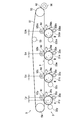
- FIG. 3 is a diagram showing a power supply system for the four primary transfer rollers 52y, 52c, 52m, and 52bk.
- the transfer unit 5 further includes a power supply unit 57 connected to the four primary transfer rollers 52y, 52c, 52m, and 52bk.
- the power supply unit 57 can charge the primary transfer rollers 52y, 52c, 52m, and 52bk.
- the power supply unit 57 includes one constant voltage source 58 (first power supply device) connected to the four primary transfer rollers 52y, 52c, 52m, and 52bk.
- the constant voltage source 58 applies a bias voltage (transfer voltage) to each of the primary transfer rollers 52y, 52c, 52m, and 52bk at the time of primary transfer.
- the primary transfer rollers 52y, 52c, 52m, and 52bk are charged.
- the toner images carried on the peripheral surfaces of the photoconductive drums 31y, 31c, 31m, and 31bk correspond to the surface potentials of the photoconductive drums 31y, 31c, 31m, and 31bk and the corresponding primary transfer rollers 52y, 52c, Due to the potential difference (transfer electric field) between the surface potentials of 52 m and 52 bk, the image is primarily transferred to the outer peripheral surface of the rotating intermediate transfer belt 51 (transfer object).
- a negative bias voltage is generated from the constant voltage source 58.
- the bias voltage is, for example, ⁇ 1600V.
- a negative current flows from the primary transfer rollers 52y, 52c, 52m, and 52bk to the photosensitive drums 31y, 31c, 31m, and 31bk via the intermediate transfer belt 51. That is, current flows from the photosensitive drums 31y, 31c, 31m, and 31bk to the primary transfer rollers 52y, 52c, 52m, and 52bk.
- the primary transfer rollers 52y, 52c, 52m, and 52bk are offset (shifted) downstream of the corresponding photosensitive drums 31y, 31c, 31m, and 31bk with respect to the circumferential direction X of the intermediate transfer belt 51. is doing. Accordingly, the area of each primary transfer nip portion N1 is reduced by the amount of offset of each primary transfer roller 52y, 52c, 52m, 52bk.
- the primary transfer rollers 52y, 52c, 52m, and 52bk are made uniform.
- the power supply unit 57 is configured to use at least two primary transfer rollers among the primary transfer rollers 52y, 52c, 52m, and 52bk (in this embodiment, the primary transfer rollers 52y, 52c, 52m, and 52bk).
- Including a power supply device in this embodiment, a constant voltage source 58. Therefore, the number of power supply devices (constant voltage sources in this embodiment) can be reduced rather than the number of primary transfer rollers, and the image forming apparatus 1 can be simplified and miniaturized.
- the current flowing into the photosensitive drum flows from the primary transfer roller in the thickness direction of the intermediate transfer belt. For this reason, the current flowing into the photosensitive drum is affected by the volume resistivity of the intermediate transfer belt. As a result, the current value of the current flowing into the photosensitive drum may change due to variations in the thickness of the intermediate transfer belt (change in volume resistivity).
- the variation in the thickness of the intermediate transfer belt increases, so the current value of the current flowing into the photosensitive drum is Easy to change.
- the primary transfer rollers 52y, 52c, 52m, and 52bk are offset (shifted). For this reason, current easily flows into the photosensitive drums 31y, 31c, 31m, and 31bk through the surface of the intermediate transfer belt 51. As a result, the influence of the volume resistivity of the intermediate transfer belt 51 having a large change on the current value of the current flowing into the photosensitive drums 31y, 31c, 31m, and 31bk is reduced, and the surface resistance of the intermediate transfer belt 51 having a small change is reduced. The effect of rate increases. Therefore, the current value of the current flowing into the photosensitive drums 31y, 31c, 31m, and 31bk can be more stably suppressed and made uniform.
- the plus DC charging roller method is adopted as the charging method of the photosensitive drums 31y, 31c, 31m, and 31bk.
- a transfer memory is likely to occur.
- the primary transfer rollers 52y, 52c, 52m, and 52bk are offset (shifted), the current value of the current flowing into the photosensitive drums 31y, 31c, 31m, and 31bk is suppressed. Therefore, even in the configuration in which the plus DC charging roller system is employed, the current value of the current flowing into the photosensitive drums 31y, 31c, 31m, and 31bk can be suppressed and uniformized.
- static elimination before transfer is performed on the photosensitive drums 31c, 31m, and 31bk. According to such a configuration, generation of a transfer memory can be further suppressed.
- the pre-transfer static elimination is performed on the photosensitive drums 31c, 31m, and 31bk excluding the photosensitive drum 31y located on the most upstream side in the circumferential direction X of the intermediate transfer belt 51.
- the surface potential of the photoconductor drum 31y becomes higher than that of the other photoconductor drums 31c, 31m, and 31bk, and the current value of the current flowing into the photoconductor drum 31y becomes the other photoconductor drum 31c, There is a concern that the current may flow larger than 31 m and 31 bk.
- the primary transfer roller 52y is offset (shifted), the current value of the current flowing into the photosensitive drum 31y is suppressed.
- the photosensitive layer thickness may vary among the photosensitive drums 31y, 31c, 31m, and 31bk.
- the film thickness of the photosensitive layer of the photosensitive drum that has not been replaced it is thinner than other photosensitive drums.
- the current value of the current flowing into the non-replaced photoconductor drum may be larger than the current value of the current flowing into another photoconductor drum.
- the primary transfer rollers 52y, 52c, 52m, and 52bk are offset (shifted), the current value of the current flowing into the photosensitive drums 31y, 31c, 31m, and 31bk is suppressed. Therefore, even if the film thicknesses of the photosensitive layers of the photosensitive drums 31y, 31c, 31m, and 31bk vary, the current value of the current flowing into the photosensitive drums 31y, 31c, 31m, and 31bk is suppressed to be uniform. Can do.
- the amounts Ly, Lc, and Lm of the primary transfer rollers 52y, 52c, 52m, and 52bk are offset (shifted) with respect to the corresponding photosensitive drums 31y, 31c, 31m, and 31bk, respectively.
- Lbk (hereinafter, the amount of offset by the primary transfer roller is referred to as “offset amount”).
- offset amount the amount of offset by the primary transfer roller is referred to as “offset amount”.
- static elimination before transfer is performed on the photosensitive drums 31c, 31m, and 31bk excluding the photosensitive drum 31y.
- the offset amount Ly (shift amount) of the primary transfer roller 52y is set larger than the offset amounts Lc, Lm, and Lbk (shift amounts) of the other primary transfer rollers 52c, 52m, and 52bk. Is preferred.
- the offset amounts Ly, Lc, Lm, Lbk of the primary transfer rollers 52y, 52c, 52m, 52bk are the relationship between the current value of the current flowing into the photosensitive drums 31y, 31c, 31m, 31bk and the voltage value of the bias voltage (I ⁇ V characteristics). That is, the offset amounts Ly, Lc, Lm, and Lbk are determined so that the current values of the currents flowing into the photosensitive drums 31y, 31c, 31m, and 31bk are uniform with respect to the voltage value of the bias voltage to be used.
- the offset amounts Ly, Lc, Lm, and Lbk are preferably set according to the following conditions (a) to (f). By following the conditions (a) to (f), it is possible to suppress and equalize the current value of the current flowing into the photosensitive drums 31y, 31c, 31m, and 31bk.
- A The offset amount is decreased as the surface resistivity of the intermediate transfer belt increases.
- B The offset amount is increased as the diameter of the photosensitive drum is increased.
- C The offset amount is increased as the surface potential of the photosensitive drum is higher.
- D The offset amount is decreased as the thickness of the intermediate transfer belt is increased.
- E) The offset amount is decreased as the surface resistivity of the primary transfer roller is increased.
- the offset amount is increased as the diameter of the primary transfer roller is increased.
- the offset amounts Ly, Lc, Lm, and Lbk are preferably set to 3.0 mm or more. Thereby, the current value of the current flowing into the photosensitive drums 31y, 31c, 31m, and 31bk can be suppressed and made uniform.
- the offset amount Ly can be set to 6.0 mm
- the offset amounts Lc, Lm, and Lbk can be set to 4.0 mm.
- the offset amount Ly is an offset amount of the primary transfer roller 52y that is located on the most upstream side with respect to the circumferential direction X of the intermediate transfer belt 51 among the primary transfer rollers 52y, 52c, 52m, and 52bk.
- the offset amounts Lc, Lm, and Lbk are offset amounts of the primary transfer rollers 52c, 52m, and 52bk that are located on the downstream side of the primary transfer roller 52y with respect to the circumferential direction X of the intermediate transfer belt 51.
- the offset amounts Lc, Lm, and Lbk of the primary transfer rollers 52c, 52m, and 52bk are not limited to the same case.
- the toner image (color toner image) on the intermediate transfer belt 51 increases in thickness as it progresses downstream in the circumferential direction X of the intermediate transfer belt 51. Therefore, it is preferable that a larger current flows through the photosensitive drums 31c, 31m, and 31bk than the photosensitive drums 31y, 31c, and 31m adjacent to the upstream side.
- the offset amounts Ly, Lc, Lm, and Lbk of the primary transfer rollers 52y, 52c, 52m, and 52bk may be set to be smaller as the position is on the downstream side in the circumferential direction X of the intermediate transfer belt 51.
- the current value of the current flowing into the photosensitive drums 31y, 31c, 31m, and 31bk increases as the position is downstream in the circumferential direction X of the intermediate transfer belt 51.
- the offset amounts Ly, Lc, Lm, and Lbk of the primary transfer rollers 52y, 52c, 52m, and 52bk have been described above.
- the offset amounts Ly, Lc, Lm, and Lbk preferably satisfy the relationship of the following expression (1). Ly> Lc ⁇ Lm ⁇ Lbk (1)
- the present invention is not limited to this configuration.
- the present invention is applicable to a configuration in which a bias voltage is applied to the primary transfer roller using a constant voltage source (power supply device) that is smaller than the number of primary transfer rollers.
- the present invention is also applicable to the image forming apparatus 1 including two constant voltage sources 58a and 58b as shown in FIG.
- FIG. 4 is a diagram showing another example of the power supply system for the four primary transfer rollers 52y, 52c, 52m, and 52bk.
- the transfer unit 5 includes a first constant voltage source 58a (first power supply device) and a second constant voltage source 58b (second power supply device).
- the first constant voltage source 58a includes at least two primary transfer rollers (four primary transfer rollers 52y in the example shown in FIG. 4) among the four primary transfer rollers 52y, 52c, 52m, and 52bk (a plurality of transfer members).
- 52c, 52m and the second constant voltage source 58b is connected to the remaining primary transfer roller (primary transfer roller 52bk in the example shown in FIG. 4).
- the first constant voltage source 58a applies a bias voltage to the three primary transfer rollers 52y, 52c, 52m of the four primary transfer rollers 52y, 52c, 52m, 52bk, and the second constant voltage source 58b A bias voltage is applied to one primary transfer roller 52bk.
- the primary transfer roller 52bk that is located on the most downstream side with respect to the circumferential direction X of the intermediate transfer belt 51 is set to the second fixed roller 52bk.
- a bias voltage is applied from the voltage source 58b. Therefore, a black toner image can be formed without applying a bias voltage from the first constant voltage source 58a to the primary transfer rollers 52y, 52c, and 52m other than the primary transfer roller 52bk. Therefore, it is possible to suppress power consumption when only a black toner image is formed.
- a bias voltage is applied to the primary transfer roller 52bk from a power supply device (second constant voltage source 58b) different from the other three primary transfer rollers 52y, 52c, and 52m. Therefore, the current value of the current flowing into the photosensitive drum 31bk corresponding to the primary transfer roller 52bk can be adjusted by the second constant voltage source 58b. Therefore, the primary transfer roller 52bk may be disposed immediately above the photosensitive drum 31bk without being offset (shifted). Alternatively, the primary transfer roller 52bk may be offset, and the current value of the current flowing into the photosensitive drum 31bk may be adjusted by the offset amount Lbk of the primary transfer roller 52bk and the second constant voltage source 58b.
- static elimination before transfer is performed.
- a bias voltage is applied from the first constant voltage source 58a to the three primary transfer rollers 52y, 52c, and 52m, and the three primary transfer rollers 52y, 52c, and 52m perform pre-transfer static elimination.
- a primary transfer roller 52y corresponding to the photosensitive drum 31y that is not provided is included. Therefore, in the configuration shown in FIG.
- the offset amounts Ly, Lc, and Lm of the primary transfer rollers 52y, 52c, and 52m are expressed by the following equations (1) as in the image forming apparatus 1 described with reference to FIGS. It is preferable to satisfy the relationship 2). Ly> Lc ⁇ Lm (2)
- the photosensitive drum 31 is charged to a positive potential, but the present invention is not limited to this.
- the photosensitive drum 31 may be charged to a negative potential.
- the primary transfer roller 52 is charged to a positive potential.
- the photosensitive drum 31 is charged by the roller method, but the present invention is not limited to this.
- the photosensitive drum 31 may be charged by, for example, a belt method.
- the photosensitive drum 31 is charged with a DC voltage.
- the photosensitive drum 31 may be charged by a voltage in which an AC voltage is superimposed on a DC voltage.
- the photosensitive drum 31 is charged using the proximity discharge phenomenon.
- the present invention is not limited to this.
- the photosensitive drum 31 may be charged by a scorotron method.
- the photoconductive drum 31 has a positively charged single layer type organic photoconductor, but the present invention is not limited to this.
- the photosensitive drum 31 may include a negatively charged organic photosensitive member.
- the photosensitive drum 31 may have an inorganic photosensitive member.
- the photosensitive layer of the photosensitive drum 31 may have a multilayer structure.
- the central axis of the primary transfer roller 52 is shifted downstream from the central axis of the corresponding photosensitive drum 31 with respect to the circumferential direction X (movement direction) of the intermediate transfer belt 51.
- the primary transfer roller 52 may be offset upstream. Further, it is not necessary that all the primary transfer rollers 52 are offset in the same direction. That is, with respect to the circumferential direction X of the intermediate transfer belt 51, the primary transfer roller 52 that is shifted downstream from the central axis of the corresponding photosensitive drum 31 and the upstream from the central axis of the corresponding photosensitive drum 31.
- the primary transfer roller 52 shifted to the side may be mixed.
- constant voltage source 58 or two constant voltage sources 58a and 58b are used as the power supply device for charging the four primary transfer rollers 52 has been described. Is not limited to this.
- the number of constant voltage sources (power supply devices) is not particularly limited as long as it is smaller than the number of primary transfer rollers.
- the image forming apparatus 1 includes a first constant voltage source 58 a connected to the three primary transfer rollers 52 and a second constant voltage source 58 b connected to the one primary transfer roller 52.
- a first constant voltage source 58 a connected to the three primary transfer rollers 52
- a second constant voltage source 58 b connected to the one primary transfer roller 52.
- the present invention is not limited to this.
- two constant voltage sources (power supply devices) may be connected to a plurality of primary transfer rollers, respectively.
- the connection destination of each constant voltage source (power supply device) is not particularly limited.
- constant voltage sources constant voltage sources 58, 58a, 58b
- the power supply device may be a constant current source.
- Examples 1 to 3 and Comparative Examples 1 and 2 In Examples 1 to 3 and Comparative Examples 1 and 2, a positively charged single layer type organic photosensitive drum having a diameter ⁇ of 30 mm, a primary transfer roller having a diameter ⁇ of 12.0 mm, and an intermediate having a thickness of 120 ⁇ m A transfer belt was used. Carbon was dispersed in the elastic material of the primary transfer roller to impart conductivity to the elastic material of the primary transfer roller. Similarly, carbon was dispersed in the intermediate transfer belt to impart conductivity to the intermediate transfer belt. The film thickness of the photosensitive layer of the photosensitive drum was 15 ⁇ m. The photosensitive drum was charged by a plus DC charging roller method, and the surface potential of the photosensitive drum was set to 500V.
- the surface resistivity of the primary transfer roller was 1.0 ⁇ 10 7 ⁇ / sq when 1000 V was applied, and the surface resistivity of the intermediate transfer belt was 1.0 ⁇ 10 10 ⁇ / sq when 250 V was applied. Under such conditions, a bias voltage was applied to the primary transfer roller, and the current value of the current flowing into the photosensitive drum was measured. The current value of the current flowing into the photosensitive drum was measured at the connection point between the constant voltage source and the primary transfer roller.
- Example 1 the offset value of the primary transfer roller was set to 3.0 mm, and the current value of the current flowing into the photosensitive drum was measured. That is, the primary transfer roller was shifted by 3.0 mm with respect to the photosensitive drum, and the current value of the current flowing into the photosensitive drum was measured.
- Example 2 the offset value of the primary transfer roller was set to 4.0 mm, and the current value of the current flowing into the photosensitive drum was measured. That is, the primary transfer roller was shifted by 4.0 mm with respect to the photosensitive drum, and the current value of the current flowing into the photosensitive drum was measured.
- Example 3 the offset value of the primary transfer roller was set to 6.0 mm, and the current value of the current flowing into the photosensitive drum was measured.
- the primary transfer roller was shifted by 6.0 mm with respect to the photosensitive drum, and the current value of the current flowing into the photosensitive drum was measured.
- the current value of the current flowing into the photosensitive drum was measured without offsetting (shifting) the primary transfer roller. That is, the offset value of the primary transfer roller was set to 0.0 mm, and the current value of the current flowing into the photosensitive drum was measured.
- the offset value of the primary transfer roller was set to 2.0 mm, and the current value of the current flowing into the photosensitive drum was measured. That is, the current value of the current flowing into the photosensitive drum was measured by shifting the primary transfer roller by 2.0 mm with respect to the photosensitive drum.
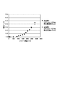
- the measurement results of Examples 1 to 3 and Comparative Examples 1 and 2 are shown in FIG.
- FIG. 5 is a diagram showing a graph (IV characteristic) in which the current value ( ⁇ A) of the current flowing into the photosensitive drum is plotted against the voltage value ( ⁇ V) of the bias voltage.
- the vertical axis represents the current value ( ⁇ A) of the current flowing into the photosensitive drum
- the horizontal axis represents the voltage value ( ⁇ V) of the bias voltage.
- the current value in the vicinity of the voltage value “ ⁇ 1600 V” of the bias voltage necessary for the primary transfer decreased when the offset amount of the primary transfer roller became 3.0 mm or more.
- the offset amounts of the primary transfer rollers 52y, 52c, 52m, and 52bk were set to “6.0 mm”, “4.0 mm”, “4.0 mm”, and “4.0 mm”, respectively.
- the current values of the currents flowing through the photosensitive drums 31y, 31c, 31m, and 31bk near the voltage value “ ⁇ 1600 V” of the bias voltage necessary for the primary transfer are “7.0 ⁇ A”, “8.0 ⁇ A”, It was found that “8.0 ⁇ A” and “8.0 ⁇ A” were obtained.
- Example 4 Comparative Example 3
- the thickness of the photosensitive layer of the photosensitive drum was set to 32 ⁇ m.
- the current value of the current flowing into the photosensitive drum was measured under the same conditions as in Example 3 and Comparative Example 1 except for the thickness of the photosensitive layer of the photosensitive drum. That is, in Example 4, as in Example 3, the offset amount of the primary transfer roller was set to 6.0 mm, and the current value of the current flowing into the photosensitive drum was measured.
- Comparative Example 3 as in Comparative Example 1, the current value of the current flowing into the photosensitive drum was measured without offsetting (shifting) the primary transfer roller.
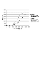
- the measurement results of Example 4 are shown in FIG. 6 together with the measurement results of Example 3.
- the measurement result of Comparative Example 3 is shown in FIG. 7 together with the measurement result of Comparative Example 1.
- FIGS. 6 and 7 are graphs (IV characteristics) in which the current value ( ⁇ A) of the current flowing into the photosensitive drum is plotted with respect to the voltage value ( ⁇ V) of the bias voltage.
- the vertical axis represents the current value ( ⁇ A) of the current flowing into the photosensitive drum
- the horizontal axis represents the voltage value ( ⁇ V) of the bias voltage
- the present invention can be suitably used for an image forming apparatus such as a copying machine, a printing machine, a facsimile machine, and a multifunction machine.
Landscapes
- Physics & Mathematics (AREA)
- General Physics & Mathematics (AREA)
- Health & Medical Sciences (AREA)
- Toxicology (AREA)
- Electrostatic Charge, Transfer And Separation In Electrography (AREA)
- Color Electrophotography (AREA)
- Discharging, Photosensitive Material Shape In Electrophotography (AREA)
Abstract
Description
(a)中間転写ベルトの表面抵抗率が大きい程、オフセット量を減少させる。
(b)感光体ドラムの直径が大きい程、オフセット量を増大させる。
(c)感光体ドラムの表面電位が高い程、オフセット量を増大させる。
(d)中間転写ベルトの厚みが大きい程、オフセット量を減少させる。
(e)一次転写ローラーの表面抵抗率が大きい程、オフセット量を減少させる。
(f)一次転写ローラーの直径が大きい程、オフセット量を増大させる。
Ly>Lc≧Lm≧Lbk (1)
Ly>Lc≧Lm (2)
実施例1~3及び比較例1、2では、30mmの直径φを有する正帯電単層型の有機感光体ドラムと、12.0mmの直径φを有する一次転写ローラーと、120μmの厚みを有する中間転写ベルトとを用いた。一次転写ローラーの弾性材にカーボンを分散させて、一次転写ローラーの弾性材に導電性を付与した。同様に、中間転写ベルトにカーボンを分散させて、中間転写ベルトに導電性を付与した。感光体ドラムの感光層の膜厚は、15μmとした。感光体ドラムをプラスDC帯電ローラー方式により帯電させて、感光体ドラムの表面電位を500Vとした。一次転写ローラーの表面抵抗率は1000V印加時に1.0×10⁷Ω/sq、中間転写ベルトの表面抵抗率は250V印加時に1.0×1010Ω/sqであった。このような条件の下、バイアス電圧を一次転写ローラーに印加して、感光体ドラムに流れ込む電流の電流値を測定した。感光体ドラムに流れ込む電流の電流値は、定電圧源と一次転写ローラーとの接続点において測定した。
実施例4及び比較例3では、感光体ドラムの感光層の膜厚を32μmとした。感光体ドラムの感光層の膜厚以外は実施例3及び比較例1と同様の条件の下、感光体ドラムに流れ込む電流の電流値を測定した。つまり、実施例4では、実施例3と同様に、一次転写ローラーのオフセット量を6.0mmに設定して、感光体ドラムに流れ込む電流の電流値を測定した。また、比較例3では、比較例1と同様に、一次転写ローラーをオフセット(シフト)させずに、感光体ドラムに流れ込む電流の電流値を測定した。実施例4の測定結果を、実施例3の測定結果と共に図6に示す。また、比較例3の測定結果を、比較例1の測定結果と共に図7に示す。
Claims (14)
- 各色のトナー像を重ねて転写することによってカラー画像を形成可能な画像形成装置であって、
異なる色の前記トナー像をそれぞれ担持可能な複数の像担持体と、
前記複数の像担持体の各々にそれぞれ対向する複数の転写部材と、
前記複数の転写部材を帯電させることにより、前記複数の像担持体が担持する前記トナー像を、移動する被転写体に転写させることが可能な電源部と
を備え、
前記電源部は、前記複数の転写部材のうちの少なくとも2つの前記転写部材に接続される第1電源装置を含み、
前記複数の転写部材のうち、前記第1電源装置に接続される前記転写部材は、それぞれ、対応する前記像担持体よりも前記被転写体の移動方向に対して上流側又は下流側にシフトして配置される、画像形成装置。 - 前記複数の像担持体の各々をそれぞれ除電する複数の除電装置を更に備え、
前記複数の除電装置のうち、隣接する前記像担持体間に配置される前記除電装置は、前記被転写体の移動方向に対して上流側及び下流側に位置する前記像担持体にそれぞれ光を照射する、請求項1に記載の画像形成装置。 - 前記第1電源装置は、前記複数の転写部材のうち、前記被転写体の移動方向に対して最も上流側に位置する前記転写部材を含む2つ以上の前記転写部材に接続される、請求項2に記載の画像形成装置。
- 前記転写部材がシフトするシフト量は、前記被転写体の移動方向に対して最も上流側に位置する前記転写部材の前記シフト量が、他の前記転写部材の前記シフト量よりも大きい、請求項3に記載の画像形成装置。
- 前記他の転写部材の前記シフト量が互いに同一である、請求項4に記載の画像形成装置。
- 前記転写部材がシフトするシフト量は、前記被転写体の移動方向に対して下流側ほど小さくなる、請求項4に記載の画像形成装置。
- 前記複数の像担持体はそれぞれ正帯電型の感光体を含み、
前記画像形成装置は、前記感光体の各々をプラスの電位にそれぞれ帯電させることが可能な複数の帯電部を更に備える、請求項1に記載の画像形成装置。 - 前記第1電源装置が、前記複数の転写部材の全てに接続している、請求項1に記載の画像形成装置。
- 前記電源部が、前記複数の転写部材のうちの1つに接続する第2電源装置を更に含む、請求項1に記載の画像形成装置。
- 前記第2電源装置に接続する前記転写部材が、対応する前記像担持体よりも前記被転写体の移動方向に対して上流側又は下流側にシフトして配置される、請求項9に記載の画像形成装置。
- 前記第2電源装置に接続する前記転写部材が、前記被転写体の移動方向において、対応する前記像担持体と同じ位置に配置される、請求項9に記載の画像形成装置。
- 前記第2電源装置は、ブラック色のトナー像を担持する前記像担持体に対向する前記転写部材に接続する、請求項9に記載の画像形成装置。
- 前記転写部材がシフトするシフト量は、3.0mm以上である、請求項4に記載の画像形成装置。
- 前記被転写体の移動方向に対して最も上流側に位置する前記転写部材の前記シフト量は、6.0mm以上である、請求項13に記載の画像形成装置。
Priority Applications (4)
| Application Number | Priority Date | Filing Date | Title |
|---|---|---|---|
| CN201580044585.XA CN106662833A (zh) | 2014-10-31 | 2015-10-05 | 图像形成装置 |
| EP15855991.4A EP3214501B1 (en) | 2014-10-31 | 2015-10-05 | Image formation device |
| JP2016556460A JP6428786B2 (ja) | 2014-10-31 | 2015-10-05 | 画像形成装置 |
| US15/506,781 US9836012B2 (en) | 2014-10-31 | 2015-10-05 | Image forming apparatus |
Applications Claiming Priority (2)
| Application Number | Priority Date | Filing Date | Title |
|---|---|---|---|
| JP2014-222827 | 2014-10-31 | ||
| JP2014222827 | 2014-10-31 |
Publications (1)
| Publication Number | Publication Date |
|---|---|
| WO2016067840A1 true WO2016067840A1 (ja) | 2016-05-06 |
Family
ID=55857184
Family Applications (1)
| Application Number | Title | Priority Date | Filing Date |
|---|---|---|---|
| PCT/JP2015/078230 Ceased WO2016067840A1 (ja) | 2014-10-31 | 2015-10-05 | 画像形成装置 |
Country Status (5)
| Country | Link |
|---|---|
| US (1) | US9836012B2 (ja) |
| EP (1) | EP3214501B1 (ja) |
| JP (1) | JP6428786B2 (ja) |
| CN (1) | CN106662833A (ja) |
| WO (1) | WO2016067840A1 (ja) |
Cited By (4)
| Publication number | Priority date | Publication date | Assignee | Title |
|---|---|---|---|---|
| JP2016090714A (ja) * | 2014-10-31 | 2016-05-23 | 京セラドキュメントソリューションズ株式会社 | 画像形成装置 |
| JP2018010175A (ja) * | 2016-07-14 | 2018-01-18 | 富士ゼロックス株式会社 | 画像形成装置 |
| JP2020012965A (ja) * | 2018-07-18 | 2020-01-23 | 京セラドキュメントソリューションズ株式会社 | 現像装置、及び画像形成装置 |
| JP2020020974A (ja) * | 2018-08-01 | 2020-02-06 | キヤノン株式会社 | 画像形成装置 |
Families Citing this family (1)
| Publication number | Priority date | Publication date | Assignee | Title |
|---|---|---|---|---|
| JP6965571B2 (ja) * | 2017-05-19 | 2021-11-10 | コニカミノルタ株式会社 | 画像形成装置及び画像形成方法 |
Citations (6)
| Publication number | Priority date | Publication date | Assignee | Title |
|---|---|---|---|---|
| JP2008122619A (ja) * | 2006-11-10 | 2008-05-29 | Ricoh Co Ltd | 画像形成装置 |
| JP2008304594A (ja) * | 2007-06-06 | 2008-12-18 | Ricoh Co Ltd | 画像形成装置、二次転写バイアスの制御方法 |
| JP2011064931A (ja) * | 2009-09-17 | 2011-03-31 | Konica Minolta Business Technologies Inc | 画像形成装置 |
| JP2011209380A (ja) * | 2010-03-29 | 2011-10-20 | Oki Data Corp | 画像形成装置 |
| JP2013113901A (ja) * | 2011-11-25 | 2013-06-10 | Kyocera Document Solutions Inc | 画像形成装置 |
| JP2014106369A (ja) * | 2012-11-27 | 2014-06-09 | Fuji Xerox Co Ltd | 画像形成装置 |
Family Cites Families (9)
| Publication number | Priority date | Publication date | Assignee | Title |
|---|---|---|---|---|
| JP4314944B2 (ja) * | 2003-09-18 | 2009-08-19 | 富士ゼロックス株式会社 | 画像形成装置 |
| JP4789534B2 (ja) * | 2005-07-29 | 2011-10-12 | キヤノン株式会社 | 画像形成装置 |
| US7761020B2 (en) * | 2006-12-13 | 2010-07-20 | Sharp Kabushiki Kaisha | Image forming apparatus utilizing cylindrical toner particles |
| JP2008191514A (ja) * | 2007-02-06 | 2008-08-21 | Canon Inc | 画像形成装置 |
| JP2009008741A (ja) * | 2007-06-26 | 2009-01-15 | Ricoh Co Ltd | 転写装置及び画像形成装置 |
| KR20110039002A (ko) * | 2009-10-09 | 2011-04-15 | 삼성전자주식회사 | 화상형성장치 |
| JP5490061B2 (ja) * | 2011-07-12 | 2014-05-14 | シャープ株式会社 | 画像形成装置のレジスト調整方法及び画像形成装置 |
| JP2013156402A (ja) * | 2012-01-30 | 2013-08-15 | Kyocera Document Solutions Inc | 画像形成装置 |
| US9116456B2 (en) * | 2012-10-26 | 2015-08-25 | Canon Kabushiki Kaisha | Image forming apparatus |
-
2015
- 2015-10-05 EP EP15855991.4A patent/EP3214501B1/en active Active
- 2015-10-05 WO PCT/JP2015/078230 patent/WO2016067840A1/ja not_active Ceased
- 2015-10-05 US US15/506,781 patent/US9836012B2/en active Active
- 2015-10-05 JP JP2016556460A patent/JP6428786B2/ja active Active
- 2015-10-05 CN CN201580044585.XA patent/CN106662833A/zh active Pending
Patent Citations (6)
| Publication number | Priority date | Publication date | Assignee | Title |
|---|---|---|---|---|
| JP2008122619A (ja) * | 2006-11-10 | 2008-05-29 | Ricoh Co Ltd | 画像形成装置 |
| JP2008304594A (ja) * | 2007-06-06 | 2008-12-18 | Ricoh Co Ltd | 画像形成装置、二次転写バイアスの制御方法 |
| JP2011064931A (ja) * | 2009-09-17 | 2011-03-31 | Konica Minolta Business Technologies Inc | 画像形成装置 |
| JP2011209380A (ja) * | 2010-03-29 | 2011-10-20 | Oki Data Corp | 画像形成装置 |
| JP2013113901A (ja) * | 2011-11-25 | 2013-06-10 | Kyocera Document Solutions Inc | 画像形成装置 |
| JP2014106369A (ja) * | 2012-11-27 | 2014-06-09 | Fuji Xerox Co Ltd | 画像形成装置 |
Non-Patent Citations (1)
| Title |
|---|
| See also references of EP3214501A4 * |
Cited By (5)
| Publication number | Priority date | Publication date | Assignee | Title |
|---|---|---|---|---|
| JP2016090714A (ja) * | 2014-10-31 | 2016-05-23 | 京セラドキュメントソリューションズ株式会社 | 画像形成装置 |
| JP2018010175A (ja) * | 2016-07-14 | 2018-01-18 | 富士ゼロックス株式会社 | 画像形成装置 |
| JP2020012965A (ja) * | 2018-07-18 | 2020-01-23 | 京セラドキュメントソリューションズ株式会社 | 現像装置、及び画像形成装置 |
| JP2020020974A (ja) * | 2018-08-01 | 2020-02-06 | キヤノン株式会社 | 画像形成装置 |
| JP7229695B2 (ja) | 2018-08-01 | 2023-02-28 | キヤノン株式会社 | 画像形成装置 |
Also Published As
| Publication number | Publication date |
|---|---|
| US20170277111A1 (en) | 2017-09-28 |
| JP6428786B2 (ja) | 2018-11-28 |
| JPWO2016067840A1 (ja) | 2017-06-08 |
| US9836012B2 (en) | 2017-12-05 |
| CN106662833A (zh) | 2017-05-10 |
| EP3214501B1 (en) | 2020-01-29 |
| EP3214501A4 (en) | 2018-05-02 |
| EP3214501A1 (en) | 2017-09-06 |
Similar Documents
| Publication | Publication Date | Title |
|---|---|---|
| JP5358558B2 (ja) | 画像形成装置 | |
| JP6428786B2 (ja) | 画像形成装置 | |
| JP2013083951A (ja) | 画像形成装置 | |
| JP2016218155A (ja) | 画像形成装置 | |
| US8843039B2 (en) | Image forming apparatus with high-resistance layer and voltage application unit | |
| JP6961375B2 (ja) | 画像形成装置 | |
| JP2011081122A (ja) | 画像形成装置 | |
| US9977395B2 (en) | Image forming apparatus for image formation through transfer of toner images to transfer target in superimposed manner | |
| JP2016133782A (ja) | 画像形成装置 | |
| JP5465071B2 (ja) | 画像形成装置 | |
| JP6365244B2 (ja) | 画像形成装置 | |
| JP2019159097A (ja) | 像担持体および画像形成装置 | |
| JP6159694B2 (ja) | 画像形成装置 | |
| JP2016045305A (ja) | 画像形成装置及び画像形成方法 | |
| JP2012181325A (ja) | 画像形成装置 | |
| JP4658637B2 (ja) | 転写装置及びこれを備える画像形成装置 | |
| JP2017191210A (ja) | 画像形成装置 | |
| JP2017026780A (ja) | 画像形成装置 | |
| JP6131748B2 (ja) | 給電構造、帯電装置、画像形成装置 | |
| JP2006189704A (ja) | 画像形成装置 | |
| JP2015222405A (ja) | 画像形成装置 | |
| JP2011095582A (ja) | 画像形成装置 | |
| US20070048030A1 (en) | Image forming apparatus | |
| JP2006154233A (ja) | 画像形成装置 | |
| JP2011095579A (ja) | 画像形成装置 |
Legal Events
| Date | Code | Title | Description |
|---|---|---|---|
| 121 | Ep: the epo has been informed by wipo that ep was designated in this application |
Ref document number: 15855991 Country of ref document: EP Kind code of ref document: A1 |
|
| ENP | Entry into the national phase |
Ref document number: 2016556460 Country of ref document: JP Kind code of ref document: A |
|
| REEP | Request for entry into the european phase |
Ref document number: 2015855991 Country of ref document: EP |
|
| WWE | Wipo information: entry into national phase |
Ref document number: 2015855991 Country of ref document: EP |
|
| WWE | Wipo information: entry into national phase |
Ref document number: 15506781 Country of ref document: US |
|
| NENP | Non-entry into the national phase |
Ref country code: DE |