WO2016067905A1 - 熱線遮蔽粒子、熱線遮蔽粒子分散液、熱線遮蔽粒子分散体、熱線遮蔽粒子分散体合わせ透明基材、赤外線吸収透明基材、熱線遮蔽粒子の製造方法 - Google Patents
熱線遮蔽粒子、熱線遮蔽粒子分散液、熱線遮蔽粒子分散体、熱線遮蔽粒子分散体合わせ透明基材、赤外線吸収透明基材、熱線遮蔽粒子の製造方法 Download PDFInfo
- Publication number
- WO2016067905A1 WO2016067905A1 PCT/JP2015/078885 JP2015078885W WO2016067905A1 WO 2016067905 A1 WO2016067905 A1 WO 2016067905A1 JP 2015078885 W JP2015078885 W JP 2015078885W WO 2016067905 A1 WO2016067905 A1 WO 2016067905A1
- Authority
- WO
- WIPO (PCT)
- Prior art keywords
- ray shielding
- heat ray
- heat
- particle dispersion
- resin
- Prior art date
- Legal status (The legal status is an assumption and is not a legal conclusion. Google has not performed a legal analysis and makes no representation as to the accuracy of the status listed.)
- Ceased
Links
Images
Classifications
-
- C—CHEMISTRY; METALLURGY
- C01—INORGANIC CHEMISTRY
- C01G—COMPOUNDS CONTAINING METALS NOT COVERED BY SUBCLASSES C01D OR C01F
- C01G41/00—Compounds of tungsten
- C01G41/006—Compounds containing tungsten, with or without oxygen or hydrogen, and containing two or more other elements
-
- C—CHEMISTRY; METALLURGY
- C09—DYES; PAINTS; POLISHES; NATURAL RESINS; ADHESIVES; COMPOSITIONS NOT OTHERWISE PROVIDED FOR; APPLICATIONS OF MATERIALS NOT OTHERWISE PROVIDED FOR
- C09D—COATING COMPOSITIONS, e.g. PAINTS, VARNISHES OR LACQUERS; FILLING PASTES; CHEMICAL PAINT OR INK REMOVERS; INKS; CORRECTING FLUIDS; WOODSTAINS; PASTES OR SOLIDS FOR COLOURING OR PRINTING; USE OF MATERIALS THEREFOR
- C09D7/00—Features of coating compositions, not provided for in group C09D5/00; Processes for incorporating ingredients in coating compositions
- C09D7/40—Additives
- C09D7/48—Stabilisers against degradation by oxygen, light or heat
-
- C—CHEMISTRY; METALLURGY
- C01—INORGANIC CHEMISTRY
- C01G—COMPOUNDS CONTAINING METALS NOT COVERED BY SUBCLASSES C01D OR C01F
- C01G41/00—Compounds of tungsten
-
- C—CHEMISTRY; METALLURGY
- C01—INORGANIC CHEMISTRY
- C01G—COMPOUNDS CONTAINING METALS NOT COVERED BY SUBCLASSES C01D OR C01F
- C01G41/00—Compounds of tungsten
- C01G41/02—Oxides; Hydroxides
-
- C—CHEMISTRY; METALLURGY
- C08—ORGANIC MACROMOLECULAR COMPOUNDS; THEIR PREPARATION OR CHEMICAL WORKING-UP; COMPOSITIONS BASED THEREON
- C08K—Use of inorganic or non-macromolecular organic substances as compounding ingredients
- C08K3/00—Use of inorganic substances as compounding ingredients
- C08K3/18—Oxygen-containing compounds, e.g. metal carbonyls
- C08K3/20—Oxides; Hydroxides
- C08K3/22—Oxides; Hydroxides of metals
-
- C—CHEMISTRY; METALLURGY
- C08—ORGANIC MACROMOLECULAR COMPOUNDS; THEIR PREPARATION OR CHEMICAL WORKING-UP; COMPOSITIONS BASED THEREON
- C08L—COMPOSITIONS OF MACROMOLECULAR COMPOUNDS
- C08L101/00—Compositions of unspecified macromolecular compounds
-
- C—CHEMISTRY; METALLURGY
- C09—DYES; PAINTS; POLISHES; NATURAL RESINS; ADHESIVES; COMPOSITIONS NOT OTHERWISE PROVIDED FOR; APPLICATIONS OF MATERIALS NOT OTHERWISE PROVIDED FOR
- C09D—COATING COMPOSITIONS, e.g. PAINTS, VARNISHES OR LACQUERS; FILLING PASTES; CHEMICAL PAINT OR INK REMOVERS; INKS; CORRECTING FLUIDS; WOODSTAINS; PASTES OR SOLIDS FOR COLOURING OR PRINTING; USE OF MATERIALS THEREFOR
- C09D17/00—Pigment pastes, e.g. for mixing in paints
-
- C—CHEMISTRY; METALLURGY
- C09—DYES; PAINTS; POLISHES; NATURAL RESINS; ADHESIVES; COMPOSITIONS NOT OTHERWISE PROVIDED FOR; APPLICATIONS OF MATERIALS NOT OTHERWISE PROVIDED FOR
- C09D—COATING COMPOSITIONS, e.g. PAINTS, VARNISHES OR LACQUERS; FILLING PASTES; CHEMICAL PAINT OR INK REMOVERS; INKS; CORRECTING FLUIDS; WOODSTAINS; PASTES OR SOLIDS FOR COLOURING OR PRINTING; USE OF MATERIALS THEREFOR
- C09D201/00—Coating compositions based on unspecified macromolecular compounds
-
- C—CHEMISTRY; METALLURGY
- C09—DYES; PAINTS; POLISHES; NATURAL RESINS; ADHESIVES; COMPOSITIONS NOT OTHERWISE PROVIDED FOR; APPLICATIONS OF MATERIALS NOT OTHERWISE PROVIDED FOR
- C09D—COATING COMPOSITIONS, e.g. PAINTS, VARNISHES OR LACQUERS; FILLING PASTES; CHEMICAL PAINT OR INK REMOVERS; INKS; CORRECTING FLUIDS; WOODSTAINS; PASTES OR SOLIDS FOR COLOURING OR PRINTING; USE OF MATERIALS THEREFOR
- C09D4/00—Coating compositions, e.g. paints, varnishes or lacquers, based on organic non-macromolecular compounds having at least one polymerisable carbon-to-carbon unsaturated bond ; Coating compositions, based on monomers of macromolecular compounds of groups C09D183/00 - C09D183/16
-
- C—CHEMISTRY; METALLURGY
- C09—DYES; PAINTS; POLISHES; NATURAL RESINS; ADHESIVES; COMPOSITIONS NOT OTHERWISE PROVIDED FOR; APPLICATIONS OF MATERIALS NOT OTHERWISE PROVIDED FOR
- C09D—COATING COMPOSITIONS, e.g. PAINTS, VARNISHES OR LACQUERS; FILLING PASTES; CHEMICAL PAINT OR INK REMOVERS; INKS; CORRECTING FLUIDS; WOODSTAINS; PASTES OR SOLIDS FOR COLOURING OR PRINTING; USE OF MATERIALS THEREFOR
- C09D5/00—Coating compositions, e.g. paints, varnishes or lacquers, characterised by their physical nature or the effects produced; Filling pastes
- C09D5/32—Radiation-absorbing paints
-
- C—CHEMISTRY; METALLURGY
- C09—DYES; PAINTS; POLISHES; NATURAL RESINS; ADHESIVES; COMPOSITIONS NOT OTHERWISE PROVIDED FOR; APPLICATIONS OF MATERIALS NOT OTHERWISE PROVIDED FOR
- C09D—COATING COMPOSITIONS, e.g. PAINTS, VARNISHES OR LACQUERS; FILLING PASTES; CHEMICAL PAINT OR INK REMOVERS; INKS; CORRECTING FLUIDS; WOODSTAINS; PASTES OR SOLIDS FOR COLOURING OR PRINTING; USE OF MATERIALS THEREFOR
- C09D7/00—Features of coating compositions, not provided for in group C09D5/00; Processes for incorporating ingredients in coating compositions
- C09D7/40—Additives
-
- C—CHEMISTRY; METALLURGY
- C09—DYES; PAINTS; POLISHES; NATURAL RESINS; ADHESIVES; COMPOSITIONS NOT OTHERWISE PROVIDED FOR; APPLICATIONS OF MATERIALS NOT OTHERWISE PROVIDED FOR
- C09D—COATING COMPOSITIONS, e.g. PAINTS, VARNISHES OR LACQUERS; FILLING PASTES; CHEMICAL PAINT OR INK REMOVERS; INKS; CORRECTING FLUIDS; WOODSTAINS; PASTES OR SOLIDS FOR COLOURING OR PRINTING; USE OF MATERIALS THEREFOR
- C09D7/00—Features of coating compositions, not provided for in group C09D5/00; Processes for incorporating ingredients in coating compositions
- C09D7/40—Additives
- C09D7/60—Additives non-macromolecular
- C09D7/61—Additives non-macromolecular inorganic
-
- C—CHEMISTRY; METALLURGY
- C09—DYES; PAINTS; POLISHES; NATURAL RESINS; ADHESIVES; COMPOSITIONS NOT OTHERWISE PROVIDED FOR; APPLICATIONS OF MATERIALS NOT OTHERWISE PROVIDED FOR
- C09D—COATING COMPOSITIONS, e.g. PAINTS, VARNISHES OR LACQUERS; FILLING PASTES; CHEMICAL PAINT OR INK REMOVERS; INKS; CORRECTING FLUIDS; WOODSTAINS; PASTES OR SOLIDS FOR COLOURING OR PRINTING; USE OF MATERIALS THEREFOR
- C09D7/00—Features of coating compositions, not provided for in group C09D5/00; Processes for incorporating ingredients in coating compositions
- C09D7/40—Additives
- C09D7/65—Additives macromolecular
-
- C—CHEMISTRY; METALLURGY
- C09—DYES; PAINTS; POLISHES; NATURAL RESINS; ADHESIVES; COMPOSITIONS NOT OTHERWISE PROVIDED FOR; APPLICATIONS OF MATERIALS NOT OTHERWISE PROVIDED FOR
- C09D—COATING COMPOSITIONS, e.g. PAINTS, VARNISHES OR LACQUERS; FILLING PASTES; CHEMICAL PAINT OR INK REMOVERS; INKS; CORRECTING FLUIDS; WOODSTAINS; PASTES OR SOLIDS FOR COLOURING OR PRINTING; USE OF MATERIALS THEREFOR
- C09D7/00—Features of coating compositions, not provided for in group C09D5/00; Processes for incorporating ingredients in coating compositions
- C09D7/40—Additives
- C09D7/66—Additives characterised by particle size
- C09D7/67—Particle size smaller than 100 nm
-
- C—CHEMISTRY; METALLURGY
- C09—DYES; PAINTS; POLISHES; NATURAL RESINS; ADHESIVES; COMPOSITIONS NOT OTHERWISE PROVIDED FOR; APPLICATIONS OF MATERIALS NOT OTHERWISE PROVIDED FOR
- C09D—COATING COMPOSITIONS, e.g. PAINTS, VARNISHES OR LACQUERS; FILLING PASTES; CHEMICAL PAINT OR INK REMOVERS; INKS; CORRECTING FLUIDS; WOODSTAINS; PASTES OR SOLIDS FOR COLOURING OR PRINTING; USE OF MATERIALS THEREFOR
- C09D7/00—Features of coating compositions, not provided for in group C09D5/00; Processes for incorporating ingredients in coating compositions
- C09D7/40—Additives
- C09D7/66—Additives characterised by particle size
- C09D7/68—Particle size between 100-1000 nm
-
- C—CHEMISTRY; METALLURGY
- C09—DYES; PAINTS; POLISHES; NATURAL RESINS; ADHESIVES; COMPOSITIONS NOT OTHERWISE PROVIDED FOR; APPLICATIONS OF MATERIALS NOT OTHERWISE PROVIDED FOR
- C09K—MATERIALS FOR MISCELLANEOUS APPLICATIONS, NOT PROVIDED FOR ELSEWHERE
- C09K3/00—Materials not provided for elsewhere
-
- G—PHYSICS
- G02—OPTICS
- G02B—OPTICAL ELEMENTS, SYSTEMS OR APPARATUS
- G02B5/00—Optical elements other than lenses
- G02B5/20—Filters
- G02B5/208—Filters for use with infrared or ultraviolet radiation, e.g. for separating visible light from infrared and/or ultraviolet radiation
-
- G—PHYSICS
- G02—OPTICS
- G02B—OPTICAL ELEMENTS, SYSTEMS OR APPARATUS
- G02B5/00—Optical elements other than lenses
- G02B5/20—Filters
- G02B5/22—Absorbing filters
- G02B5/223—Absorbing filters containing organic substances, e.g. dyes, inks or pigments
-
- C—CHEMISTRY; METALLURGY
- C01—INORGANIC CHEMISTRY
- C01P—INDEXING SCHEME RELATING TO STRUCTURAL AND PHYSICAL ASPECTS OF SOLID INORGANIC COMPOUNDS
- C01P2004/00—Particle morphology
- C01P2004/60—Particles characterised by their size
- C01P2004/62—Submicrometer sized, i.e. from 0.1-1 micrometer
-
- C—CHEMISTRY; METALLURGY
- C01—INORGANIC CHEMISTRY
- C01P—INDEXING SCHEME RELATING TO STRUCTURAL AND PHYSICAL ASPECTS OF SOLID INORGANIC COMPOUNDS
- C01P2004/00—Particle morphology
- C01P2004/60—Particles characterised by their size
- C01P2004/64—Nanometer sized, i.e. from 1-100 nanometer
-
- C—CHEMISTRY; METALLURGY
- C01—INORGANIC CHEMISTRY
- C01P—INDEXING SCHEME RELATING TO STRUCTURAL AND PHYSICAL ASPECTS OF SOLID INORGANIC COMPOUNDS
- C01P2006/00—Physical properties of inorganic compounds
- C01P2006/60—Optical properties, e.g. expressed in CIELAB-values
Definitions
- the present invention relates to a heat ray shielding particle, a heat ray shielding particle dispersion, a heat ray shielding particle dispersion, a heat ray shielding particle dispersion combined transparent base material, an infrared absorbing transparent base material, and a method for producing heat ray shielding particles.
- the heat ray shielding technique using a dispersion of conductive fine particles has advantages such as excellent heat ray shielding characteristics, low cost, radio wave permeability, and high weather resistance as compared with other techniques.
- Patent Literature 1 discloses an infrared-absorbing synthetic resin molded product in which a transparent synthetic resin containing tin oxide fine powder in a dispersed state is molded into a sheet or film, and this is laminated and integrated on a transparent synthetic resin substrate. Proposed.
- Patent Document 3 ruthenium oxide fine particles, titanium nitride fine particles, tantalum nitride fine particles, titanium silicide fine particles, molybdenum nitride fine particles, lanthanum boride fine particles, iron oxide fine particles, iron oxide hydroxide having an average particle size of 100 nm or less.
- Patent Document 3 ruthenium oxide fine particles, titanium nitride fine particles, tantalum nitride fine particles, titanium silicide fine particles, molybdenum nitride fine particles, lanthanum boride fine particles, iron oxide fine particles, iron oxide hydroxide having an average particle size of 100 nm or less.
- Patent Documents 1 to 3 have a problem that the heat ray shielding performance is not sufficient when high visible light transmittance is required.
- visible light transmittance calculated based on JIS R 3106 and solar radiation transmission calculated based on JIS R 3106 are also used. Rate.
- the visible light transmittance calculated based on JIS R 3106 and the solar light transmittance calculated based on JIS R 3106 are hereinafter simply referred to as “visible light transmittance” and “sunlight transmittance”. Describe.
- Patent Document 4 discloses an infrared shielding material fine particle dispersion in which infrared shielding material fine particles are dispersed in a medium, and the infrared shielding material fine particles are tungsten oxide fine particles and / or composite tungsten oxide fine particles. And an infrared shielding material fine particle dispersion in which the particle size of the infrared shielding material fine particles is 1 nm or more and 800 nm or less.
- Patent Document 4 for example, Cu 0.2 WO 2.72 , Al 0.1 WO 2.72 , Mn 0.1 WO 2.72 , In 0.3 WO 3 and Ba 0.21 WO 3 are used as the infrared shielding material fine particles. , Cs 0.33 WO 3 etc. are disclosed in the examples.
- the heat ray shielding dispersion using the composite tungsten oxide fine particles disclosed in Patent Document 4 showed high heat ray shielding performance, and the solar radiation transmittance when the visible light transmittance was 70% was improved to below 50%.
- the composite tungsten oxide fine particles contained in the infrared shielding material fine particle dispersion disclosed in Patent Document 4 have a high light absorption intensity per unit concentration (hereinafter, also simply referred to as “coloring power”). There was a demand to further increase the coloring power in order to improve performance.
- Patent Document 5 the applicants disclosed in a near-infrared shielding material fine particle dispersion in which near-infrared shielding material fine particles are dispersed in a medium, wherein the near-infrared shielding material fine particles have the general formula Li x M y WO z (however, , M is one or more elements selected from Cs, Rb, K, Na, Ba, Ca, Sr and Mg, W is tungsten, O is oxygen, 0.1 ⁇ x ⁇ 1.0, 0 0.1 ⁇ y ⁇ 0.5, 2.2 ⁇ z ⁇ 3.0), and the composite tungsten oxide fine particles have a hexagonal crystal structure. And a near-infrared shielding material fine particle dispersion, wherein the near-infrared shielding material fine particles have a particle diameter of 1 nm to 500 nm.
- Patent Document 5 discloses an example using Li 0.20 Cs 0.33 WO 3 fine particles or Li 0.10 Cs 0.33 WO 3 fine particles as near-infrared shielding material fine particles in Examples. And the amount of filler used necessary to make the visible light transmittance 70% or more when the solar radiation shielding transmittance is 40%, compared with the comparative example using Cs 0.33 WO 3 as the near-infrared shielding material fine particles. It has been shown that can be reduced. That is, near-infrared shielding material fine particles with improved coloring power are disclosed.
- Japanese Laid-Open Patent Publication No. 02-136230 Japanese Unexamined Patent Publication No. 08-259279 Japanese Laid-Open Patent Publication No. 11-181336 International Publication No. 2005/037932 Japanese Unexamined Patent Publication No. 2011-63493
- the Li 0.20 Cs 0.33 WO 3 fine particles and the Li 0.10 Cs 0.33 WO 3 fine particles which are the composite tungsten oxide fine particles disclosed in Patent Document 5 as described above, are used in the periphery.
- the visible light transmittance may be lowered, which is problematic in terms of weather resistance.
- an object of one aspect of the present invention is to provide heat ray shielding particles having both coloring power and weather resistance.
- Li x M y WO z a composite tungsten oxide particles having a hexagonal crystal structure
- the element M in the general formula is one or more elements selected from alkali metals excluding lithium and alkaline earth metals,
- heat ray shielding particles having both coloring power and weather resistance can be provided.
- the heat ray shielding particles of this embodiment are represented by the general formula Li x M y WO z and can be composite tungsten oxide particles having a hexagonal crystal structure.
- the element M in the above general formula can be one or more elements selected from alkali metals other than lithium and alkaline earth metals.
- x, y and z in the above general formula preferably satisfy 0.25 ⁇ x ⁇ 0.80, 0.10 ⁇ y ⁇ 0.50, and 2.20 ⁇ z ⁇ 3.00, respectively.
- Li represents lithium
- W represents tungsten
- O oxygen
- the inventors of the present invention have made extensive studies in order to obtain heat ray shielding particles excellent in coloring power and weather resistance as described above. And it discovered that it could be set as the heat ray shielding particle excellent in coloring power and a weather resistance by dopeing a predetermined amount of lithium atoms to the composite tungsten oxide which has a hexagonal crystal structure, and completed this invention.
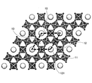
- FIG. 1 shows a projection when the crystal structure of Cs 0.33 WO 3 is viewed from the (001) direction as an example of a composite tungsten oxide having a hexagonal crystal structure.
- hexagonal columnar voids 12 (tunnels).
- triangular columnar voids 13 In the example shown in FIG. 1, cesium 121 is arranged in the hexagonal columnar gap 12.
- the unit cell 10 of the composite tungsten oxide having a hexagonal crystal structure has two triangular columnar voids 13 for each hexagonal columnar void 12. . Since the triangular columnar voids 13 are small in size, it can be considered that doping can be performed as long as lithium atoms have a small atomic radius.
- the composite tungsten oxide having a hexagonal crystal as described above for example, among the triangular prism-shaped voids 13 having two per unit cell, 1
- One or two lithium atoms can be arranged.
- the hexagonal crystal structure and the arrangement of other atoms existing in the hexagonal columnar voids 12 are energetically stabilized.
- the hexagonal crystal structure and the arrangement of other atoms existing in the hexagonal columnar voids 12 are energetically stabilized by doping lithium atoms, thereby improving the weather resistance of the composite tungsten oxide. It is considered possible.
- Heat ray shielding particles thus, in the above embodiment is denoted by the general formula Li x M y WO z as described above, a composite tungsten oxide particles having a hexagonal crystal structure, a predetermined content of Li atoms By setting it as this range, it can be set as the heat ray shielding particle which has coloring power and a weather resistance.
- the molar ratio x of lithium element to the tungsten element is preferably 0.25 or more 0.80 or less.
- the molar ratio x of lithium element to tungsten element is 0.25 or more, so that the hexagonal crystal structure and the arrangement of other atoms present in the hexagonal columnar voids are energetically stable.
- the free power of lithium atoms injected into the crystal as described above increases the coloring power. Therefore, the molar ratio x of lithium element to tungsten element is 0. By setting the ratio to 25 or more, the coloring power can be increased.
- Lithium atoms doped in the composite tungsten oxide are mainly doped into the triangular columnar voids 13 shown in FIG. 1.
- the triangular columnar voids 13 are saturated, for example, the hexagonal columnar voids 12 are also doped. be able to. For this reason, it is preferable to dope lithium more than 0.67 in order to reliably fill the lithium in the triangular columnar gaps 13.
- the molar ratio x of the lithium element to the tungsten element is preferably 0.80 or less.
- the composite tungsten oxide has a hexagonal crystal structure and other hexagonal column-shaped voids when one or two of the two triangular column-shaped voids of the unit cell are substantially uniformly filled. It is possible to improve the weather resistance by stabilizing the arrangement of the atoms in terms of energy. For this reason, the molar ratio x of the lithium element to the tungsten element is preferably in the vicinity of 0.33 or 0.67. Therefore, specifically, the molar ratio x of the lithium element to the tungsten element is more preferably 0.25 or more and 0.45 or less, or 0.55 or more and 0.75 or less.
- the composite tungsten oxide can dope lithium atoms substantially uniformly in one of the two triangular columnar voids in the unit cell.
- the composite tungsten oxide can be doped with lithium atoms substantially uniformly in both of the two triangular columnar voids in the unit cell.
- the element M As the element M, one or more elements selected from alkali metals other than lithium and alkaline earth metals as described above can be preferably used. That is, as the element M, sodium (Na), potassium (K), rubidium (Rb), cesium (Cs), francium (Fr), calcium (Ca), strontium (Sr), barium (Ba), radium (Ra) One or more elements selected from can be preferably used.
- the element M is more preferably one or more elements selected from cesium, rubidium, potassium, and sodium.
- the crystal structure of the composite tungsten oxide is particularly likely to be a hexagonal crystal, and the structure is stabilized, so that the weather resistance is particularly improved. Because it can.
- the light transmittance in the visible region is high and the light transmittance in the infrared region, particularly the near infrared region, is low, the light transmittance in the visible region and the light transmittance in the infrared region are This is because the contrast can be increased.
- the molar ratio y of the element M to the tungsten element is preferably 0.10 or more and 0.50 or less, more preferably 0.20 or more and 0.45 or less, and further preferably 0.25 or more and 0.40 or less.
- the molar ratio y of the element M to the tungsten element is 0.10 or more, the heat ray absorption effect can be sufficiently exhibited.
- the element M is doped into the hexagonal columnar voids as described above.
- the molar ratio y of the element M to the tungsten element is excessively increased, the compound of the element M is precipitated and the heat ray absorption effect is obtained. It may be reduced.
- the molar ratio y of the element M to the tungsten element is preferably 0.50 or less.
- the molar ratio z of oxygen to tungsten element is preferably 2.20 or more and 3.00 or less.
- tungsten oxide (WO Z ) to which lithium or element M is not added also has infrared absorption characteristics.
- tungsten oxide since effective free electrons do not exist in tungsten trioxide (WO 3 ), the absorption and reflection characteristics in the near infrared region are small. For this reason, by making y which is the ratio of oxygen element to tungsten element of tungsten oxide (WO y ) less than 3, free electrons are generated in the tungsten oxide, and efficient infrared absorbing particles are obtained. Can do.
- the molar ratio z of the oxygen element to the tungsten element is preferably set to 3.00 or less.
- the molar ratio z of the oxygen element to the tungsten element is preferably 2.20 or more and 3.00 or less as described above.
- the particle diameter of the heat ray shielding particles of the present embodiment is not particularly limited and can be arbitrarily selected.
- light in the near-infrared region that is required depending on the use and purpose of the heat ray shielding particles, heat ray shielding particle dispersion using the heat ray shielding particles, heat ray shielding particle dispersion, heat ray shielding particle dispersion and transparent base material, etc.
- the volume average particle diameter of the heat ray shielding particles of the present embodiment is preferably 1 nm or more and 500 nm or less. If the volume particle diameter is 500 nm or less, strong near-infrared absorption by the heat ray shielding particles of the present embodiment can be exhibited. If the volume average particle diameter is 1 nm or more, industrial production is easy. Because.
- the heat ray shielding particles when used for a heat ray shielding particle dispersion using heat ray shielding particles, a heat ray shielding particle dispersion, or the like where transparency is required, the heat ray shielding particles preferably have a volume average particle diameter of 40 nm or less.
- the volume average particle size of the heat ray shielding particles is 40 nm or less, light scattering due to Mie scattering and Rayleigh scattering of the particles is sufficiently suppressed, and visibility in the visible light wavelength region is maintained, and at the same time, transparency is efficiently maintained. Because it can.
- the volume average particle diameter of the heat ray shielding particles is more preferably 30 nm or less, and even more preferably 25 nm or less, in order to further suppress scattering. .
- the volume average particle diameter means the particle diameter at an integrated value of 50% in the particle size distribution obtained by the laser diffraction / scattering method, and the volume average particle diameter has the same meaning in other portions in this specification. is doing.
- heat ray shielding particles of the present embodiment it is possible to provide heat ray shielding particles having both coloring power and weather resistance.
- the heat ray shielding particle of this embodiment is surface-treated from a viewpoint of a weather resistance improvement.
- the method for performing the surface treatment is not particularly limited.
- the surface treatment can be performed by a known method using an organic compound containing one or more selected from Si, Ti, Zr, and Al.
- the heat ray shielding particles and the organosilicon compound are mixed and subjected to hydrolysis treatment to perform surface treatment. (Method for producing heat ray shielding particles)
- grains of this embodiment is demonstrated.
- the method for producing heat ray shielding particles of the present embodiment relates to a method for producing heat ray shielding particles for producing the heat ray shielding particles described above. Then, a heat treatment can be performed on the mixture containing the lithium-containing material, the element M-containing material, and the tungsten-containing material in a mixed atmosphere of an inert gas and a reducing gas.
- a lithium-containing material, an element M-containing material, and a tungsten-containing material can be used as starting materials as described above.
- lithium-containing substance examples include, but are not limited to, lithium simple substance, lithium chloride salt, nitrate, sulfate, oxalate, oxide, carbonate, tungstate, hydroxide, and the like. Instead, various lithium-containing materials can be used. However, from the viewpoints of handling and reactivity, one or more selected from lithium carbonate and lithium hydroxide can be preferably used as the lithium-containing substance.
- the element M-containing material examples include element M alone, chloride salt, nitrate, sulfate, oxalate, oxide, carbonate, tungstate, hydroxide, etc. of element M. It is not limited to these, and various element M-containing materials can be used. However, from the viewpoint of handling and reactivity, the element M-containing material is preferably one or more selected from the carbonate of the element M, the hydroxide of the element M, and the oxide of the element M. .
- the tungsten-containing substance is not particularly limited, but for example, tungstic acid, tungsten trioxide, tungsten dioxide, tungsten oxide hydrate, tungsten hexachloride, ammonium tungstate, or tungsten hexachloride is dissolved in alcohol. Hydrate of tungsten oxide obtained by drying after being dissolved, or hydrate of tungsten oxide obtained by dissolving tungsten hexachloride in alcohol and then precipitating by adding water Alternatively, any one or more selected from a tungsten compound obtained by drying an ammonium tungstate aqueous solution and metallic tungsten can be preferably used. However, one or more selected from tungsten, tungsten oxide, tungstic acid, and ammonium tungstate can be preferably used as the tungsten-containing substance from the viewpoints of handling and reactivity.
- a mixture of starting materials including a lithium-containing material, an element M-containing material, and a tungsten-containing material can be prepared before performing the heat treatment.
- the starting material mixture is composed of lithium in the starting material mixture, and the stoichiometric ratio of the elements M and tungsten, respectively, of x, y in the general formula Li x M y WO z of the resulting composite tungsten oxide.
- the starting materials are preferably prepared by weighing and mixing so as to satisfy the range.
- the range of x and y in the general formula Li x M y WO z of the composite tungsten oxide satisfies 0.25 ⁇ x ⁇ 0.80 and 0.10 ⁇ y ⁇ 0.50 as described above. Is preferred.
- each starting material is preferably soluble in a solvent such as water or an organic solvent.
- each starting material is soluble in a solvent such as water or an organic solvent, it is possible to obtain a particularly uniformly mixed starting material mixture by volatilizing the solvent after thoroughly mixing each starting material and the solvent. it can.
- the method for preparing the mixture of starting materials is not limited to the case where the starting material mixture is dissolved in a solvent as described above.
- a mixture of starting materials can be prepared by sufficiently uniformly mixing each starting material by a known means such as a mortar or a ball mill.
- a mixed gas of an inert gas and a reducing gas can be used as described above.
- the type of inert gas and reducing gas used in this case and the conditions for heat treatment, that is, temperature and heat treatment time.
- the type of gas used and the conditions for the heat treatment can be appropriately selected so that the molar ratio of the oxygen element to the tungsten element in the structure of the composite tungsten oxide as the product satisfies 2.20 ⁇ z ⁇ 3.00. .
- hydrogen (H 2 ) can be preferably used as the reducing gas.
- hydrogen for example, argon (Ar), nitrogen (N 2 ), or the like is preferably used as the inert gas. it can.
- the composition of the mixed gas of the inert gas and the reducing gas is not particularly limited.
- the reducing gas is hydrogen
- the reducing property occupies the mixed atmosphere of the reducing gas and the inert gas.
- the gas ratio is preferably 0.1% by volume or more and 20% by volume or less.
- the ratio of the reducing gas is more preferably 0.2 volume% or more and 20 volume% or less.
- a mixture of starting materials can be heat treated at, for example, 300 ° C. or more and 900 ° C. or less. This is because the formation reaction of the composite tungsten oxide having a hexagonal crystal structure can be promoted by performing the heat treatment at 300 ° C. or higher. However, when the heat treatment temperature becomes high, composite tungsten oxide having a structure other than hexagonal crystal and unintended side reaction products such as metallic tungsten may be generated.
- heat treatment may be performed in an inert gas atmosphere as necessary.
- the heat treatment in an inert gas atmosphere is preferably performed at a temperature of 400 ° C. or higher and 1200 ° C. or lower.
- the type of the inert gas used at this time is not particularly limited, but the same gas as the inert gas used when forming the mixed atmosphere of the inert gas and the reducing gas may be used. preferable.
- the manufacturing method for manufacturing the heat ray shielding particles described above by performing the heat treatment on the mixture containing the lithium-containing material, the element M-containing material, and the tungsten-containing material has been described.
- the manufacturing method of heat ray shielding particles is not limited to the first configuration example described above.
- an inert gas and a reducing gas are mixed with a mixture containing a lithium-containing material and a composite tungsten oxide containing the element M.
- the manufacturing method of the heat ray shielding particle which heat-processes in the mixed atmosphere of these is mentioned.
- the composite tungsten oxide containing the element M that can be used in the method for producing heat ray shielding particles is not particularly limited, and examples thereof include cesium tungsten oxide, potassium tungsten oxide, and rubidium tungsten oxide.
- the lithium-containing substance is not particularly limited, but for example, the same substance as that in the method for producing the heat ray shielding particles of the first configuration example can be preferably used.
- the 3rd structural example of the manufacturing method of heat ray shielding particle can have the following processes, for example.
- the heat treatment is divided into two stages in the first configuration example of the heat ray shielding particle manufacturing method of the present embodiment described above, so that the composite tungsten oxide is more reliable.
- a hexagonal crystal structure can be formed.
- the inert gas and the reducing property are reduced with respect to the first raw material mixture containing the lithium-containing material, the element M-containing material, and the tungsten-containing material.
- Heat treatment can be performed in a mixed atmosphere with gas.
- the first raw material mixture is prepared by adding an element M-containing material that is less than the amount of the element M-containing material estimated from the composition in the target composite tungsten oxide. It is preferable to do.
- the molar ratio y1 of the element M to the tungsten element contained in the first raw material mixture can be set to 0.01 ⁇ y1 ⁇ 0.25.
- the starting material so as to satisfy the general formula Li x M y range of x in WO z in the composite tungsten oxide to be produced It is preferable to prepare by mixing.
- the range of x in the general formula Li x M y WO z of the composite tungsten oxide preferably satisfies 0.25 ⁇ x ⁇ 0.80 as described above.
- the lithium-containing material, the element M-containing material, and the tungsten-containing material contained in the first raw material mixture are not particularly limited, and for example, the same materials as those described in the first configuration example can be used. .
- the heat treatment conditions in the first heat treatment step are not particularly limited, and for example, the same conditions and gas types as those described in the first configuration example Can be used.
- the composite tungsten oxide intermediate composition represented by the general formula Li x M y1 WO z (0.25 ⁇ x ⁇ 0.80, 0.01 ⁇ y1 ⁇ 0.25) Is generated.
- heat treatment may be performed in an inert gas atmosphere as necessary.
- the heat treatment in an inert gas atmosphere is preferably performed at a temperature of 400 ° C. or higher and 1200 ° C. or lower.
- the type of inert gas used at this time is not particularly limited, but it is preferable to use the same gas as the inert gas used in the first heat treatment step.
- the second raw material mixture can be prepared by adding and mixing the element M-containing substance to the treated product obtained in the first heat treatment step, that is, the composite tungsten oxide intermediate composition.
- the molar ratio y2 of the total of the element M contained in the element M-containing material added in the second raw material mixture preparation step and the element M contained in the first raw material mixture to the tungsten element contained in the first raw material mixture is set to 0. It is possible to satisfy 10 ⁇ y2 ⁇ 0.50.
- the element M-containing material added when preparing the second raw material mixture is not particularly limited, and for example, the same materials as those described in the first configuration example can be used. Note that the element M-containing material used in preparing the first raw material mixture and the element M-containing material used in preparing the second raw material mixture may be the same or different.
- the 2nd heat treatment process which heat-processes with respect to the prepared 2nd raw material mixture in the mixed atmosphere of an inert gas and a reducing gas can be implemented.
- the heat treatment conditions in the second heat treatment step, the type of inert gas and reducing gas used, etc. are not particularly limited, and for example, the same conditions and gas types as those described in the first configuration example are used. be able to.
- the same heat treatment conditions and use gas as a 1st heat treatment process may be sufficient, the heat treatment conditions and use gas different from 1st heat treatment conditions may be sufficient.
- the heat treatment in an inert gas atmosphere is preferably performed at a temperature of 400 ° C. or higher and 1200 ° C. or lower.
- the type of inert gas used at this time is not particularly limited, but it is preferable to use the same gas as the inert gas used in the second heat treatment step.
- the composite tungsten oxide having a hexagonal crystal structure in which the lithium compound is not precipitated alone can be obtained more stably by taking the two firing steps described so far. Although the cause is not sufficiently clear, the present inventors presume the mechanism as follows.
- a hexagonal crystal structure is formed by the presence of the element M, and the above composition at this time is an element ratio satisfying at least all the hexagonal columnar voids existing in the unit cell of the hexagonal composite tungsten oxide structure, that is, It does not satisfy y ⁇ 0.33. Accordingly, since there are more voids in the hexagonal composite tungsten oxide, lithium atoms are likely to be doped into the crystal lattice, making it difficult to precipitate alone.
- the hexagonal columnar voids existing in the unit cell of the hexagonal composite tungsten oxide structure are stably filled with the element M, while the lithium atoms are It is presumed that the triangular columnar gap is doped by diffusion. With the above mechanism, it is considered that a composite tungsten oxide having a hexagonal crystal structure in which a lithium compound is not precipitated alone can be obtained.
- the heat ray shielding particle having both coloring power and weather resistance can be produced by the method of manufacturing the heat ray shielding particle of this embodiment.
- Heat ray shielding particle dispersion and its production method Next, a configuration example of the heat ray shielding particle dispersion of the present embodiment and a manufacturing method thereof will be described. In the present specification, the heat ray shielding particle dispersion may be simply referred to as “dispersion”.
- the heat ray shielding particle dispersion of this embodiment may contain the heat ray shielding particles described above and a liquid medium containing one or more kinds selected from water, organic solvents, liquid resins, and plasticizers for liquid plastics. it can.
- the heat ray shielding particles are preferably dispersed in a liquid medium.
- the heat ray shielding particle dispersion of this embodiment can contain the heat ray shielding particles of this embodiment and a liquid medium. For this reason, about a part which overlaps with the content as stated above about heat ray shielding particle
- the liquid medium used for preparing the heat ray shielding particle dispersion preferably has a function for maintaining the dispersibility of the heat ray shielding particle dispersion.
- liquid medium one containing at least one selected from water, an organic solvent, a liquid resin, and a liquid plasticizer for plastics can be used.
- water, an organic solvent, liquid resin, and a liquid plasticizer for plastics when 2 or more types selected from the above-mentioned water, an organic solvent, liquid resin, and a liquid plasticizer for plastics are contained, it can be used as a mixture of contained components.
- the liquid medium preferably has a function of maintaining the dispersibility of the heat ray shielding dispersion as described above.
- the organic solvent satisfying such requirements include alcohols, ketones, hydrocarbons, glycols, esters, amides, and the like.
- Specific examples of the organic solvent include alcohol solvents such as isopropyl alcohol, methanol, ethanol, 1-methoxy-2-propanol, 1-propanol, isopropanol, butanol, pentanol, benzyl alcohol, diacetone alcohol; acetone, Ketone solvents such as methyl ethyl ketone, methyl propyl ketone, methyl isobutyl ketone, cyclohexanone, isophorone and dimethyl ketone; ester solvents such as 3-methyl-methoxy-propionate and n-butyl acetate; ethylene glycol monomethyl ether, ethylene glycol monoethyl ether , Ethylene glycol iso
- organic solvents having low polarity can be preferably used.
- isopropyl alcohol, ethanol, 1-methoxy-2-propanol, dimethyl ketone, methyl ethyl ketone, methyl isobutyl ketone, toluene, propylene glycol monomethyl ether acetate, n-butyl acetate and the like can be more preferably used.
- These organic solvents can be used alone or in combination of two or more.
- liquid resin methyl methacrylate or the like can be preferably used.
- Liquid plasticizers include plasticizers that are compounds of monohydric alcohols and organic acid esters, ester plasticizers such as polyhydric alcohol organic acid ester compounds, and phosphoric acids such as organic phosphate plasticizers.
- a plasticizer that is a system can be preferably used.
- triethylene glycol di-2-ethylhexanoate, triethylene glycol di-2-ethylbutyrate, and tetraethylene glycol di-2-ethylhexanoate are more preferably used because of their low hydrolyzability. it can.
- a dispersant In addition to the above-mentioned liquid medium, a dispersant, a coupling agent, a surfactant, and the like can be added to the heat ray shielding particle dispersion of this embodiment as desired. These components will be described.
- Dispersing agents, coupling agents, and surfactants can be selected according to the use, but preferably have an amine-containing group, a hydroxyl group, a carboxyl group, or an epoxy group as a functional group. These functional groups are adsorbed on the surface of the heat ray shielding particles to prevent aggregation of the heat ray shielding particles, and the heat ray shielding particles can be uniformly dispersed even in a heat ray shielding particle dispersion or a heat ray shielding particle dispersion described later.
- a phosphate ester compound for example, a phosphate ester compound, a polymer dispersing agent, a silane coupling agent, a titanate coupling agent, an aluminum coupling agent, or the like can be preferably used.
- the polymer dispersant include acrylic polymer dispersants, urethane polymer dispersants, acrylic / block copolymer polymer dispersants, polyether dispersants, and polyester polymer dispersants.
- a dispersing agent is not limited to these, Various dispersing agents can be used.
- the addition amount is not particularly limited. For example, it is preferably 10 parts by mass or more and 1000 parts by mass or less, and 20 parts by mass or more and 200 parts by mass or less with respect to 100 parts by mass of the heat ray shielding particles. More preferably.
- the heat ray shielding particles can be more reliably suppressed from aggregating in the liquid, and the dispersion stability can be maintained.
- the content of the heat ray shielding particles in the heat ray shielding particle dispersion liquid of the present embodiment is not particularly limited, and can be arbitrarily selected according to the use.
- the content of the heat ray shielding particles contained in the heat ray shielding particle dispersion of the present embodiment is preferably 0.01% by mass or more and 50% by mass or less, and 0.02% by mass or more and 20% by mass or less. More preferably, it is 0.50 mass% or more and 20 mass% or less.
- the heat ray shielding particle dispersion can have sufficient heat ray shielding performance by containing 0.01% by mass or more of the heat ray shielding particles. Moreover, since it is excellent also in handleability, it can be used suitably when manufacturing the coating layer etc. which are mentioned later.
- the heat-shielding particles increases, aggregation tends to occur in the dispersion, so that the heat-shielding particles can be kept stably dispersed, and from the viewpoint of productivity, the heat-shielding particles
- the content of is preferably 50% by mass or less.
- the heat ray shielding particle dispersion can be produced, for example, by adding and dispersing the heat ray shielding particles in a liquid medium.
- an appropriate quantity of a dispersing agent, a coupling agent, surfactant, etc. can also be added if desired.
- the method for the dispersion treatment is not particularly limited as long as the heat ray shielding particles are uniformly dispersed in the liquid medium.
- a bead mill, ball mill, sand mill, ultrasonic dispersion, or the like can be used.
- heat ray shielding particle dispersion liquid in which the heat ray shielding particles are uniformly dispersed
- various additives are added, and pH adjustment is performed. It can also be done.
- Heat ray shielding particle dispersion and method for producing the same Next, a configuration example of the heat ray shielding particle dispersion of the present embodiment and a manufacturing method thereof will be described.
- the heat ray shielding particle dispersion of the present embodiment can include the heat ray shielding particles of the present embodiment and a binder. For this reason, about a part which overlaps with the content as stated above about heat ray shielding particle
- the binder is not particularly limited as long as the binder can be solidified in a dispersed state.
- the binder preferably contains a thermoplastic resin or a UV curable resin.
- the binder can be a solid binder.
- the thermoplastic resin is not particularly limited and can be arbitrarily selected according to required transmittance, strength, and the like.
- the thermoplastic resin include polyethylene terephthalate resin, polycarbonate resin, acrylic resin, styrene resin, polyamide resin, polyethylene resin, vinyl chloride resin, olefin resin, epoxy resin, polyimide resin, fluororesin, ethylene / vinyl acetate copolymer, One kind of resin selected from the resin group of polyvinyl acetal resin, a mixture of two or more kinds of resins selected from the resin group, or a copolymer of two or more kinds of resins selected from the resin group Either of these can be preferably used.
- the UV curable resin is not particularly limited, and for example, an acrylic UV curable resin can be suitably used.
- the content of the heat ray shielding particles dispersed and contained in the heat ray shielding particle dispersion is not particularly limited, and can be arbitrarily selected according to the use.
- the content of the heat ray shielding particles in the heat ray shielding particle dispersion is, for example, preferably 0.001% by mass or more and 80.0% by mass or less, and preferably 0.01% by mass or more and 70.0% by mass or less. More preferred.
- the ratio of the binder in the heat ray shielding particle dispersion that is, the proportion of, for example, a thermoplastic resin or a UV curable resin is reduced, so that the strength is lowered. It is to do.
- the content of the heat ray shielding particles per unit projected area contained in the heat ray shielding particle dispersion is 0.04 g / m 2 or more and 4.0 g / m 2.
- the “content per unit projected area” means the weight of heat ray shielding particles contained in the thickness direction per unit area (m 2 ) through which light passes in the heat ray shielding particle dispersion of this embodiment. Means (g).
- the heat ray shielding particle dispersion can be molded into an arbitrary shape depending on the application.
- the heat ray shielding particle dispersion can have, for example, a sheet shape, a board shape, or a film shape, and can be applied to various applications.
- the heat ray shielding particle dispersion can be produced by, for example, mixing the above-described binder and the heat ray shielding particles of the present embodiment, forming the mixture into a desired shape, and then curing the mixture.
- the heat ray shielding particle dispersion can be produced using, for example, the heat ray shielding dispersion described above.
- the heat ray shielding particle dispersion powder, the plasticizer dispersion liquid, and the master batch described below can be manufactured first, and then the heat ray shielding particle dispersion can be produced using the heat ray shielding particle dispersion powder and the like. . This will be specifically described below.
- a mixing step of mixing the heat ray shielding particle dispersion described above with a thermoplastic resin or a plasticizer can be performed.
- the drying process which removes the solvent component derived from a heat ray shielding particle dispersion liquid can be implemented.
- the heat ray shielding particle dispersion powder (hereinafter simply referred to as “minute”), which is a dispersion in which the heat ray shielding particles are dispersed at a high concentration in the thermoplastic resin and / or the dispersant derived from the heat ray shielding particle dispersion.
- a dispersion in which the heat ray shielding particles are dispersed at a high concentration in the plasticizer hereinafter, sometimes simply referred to as “plasticizer dispersion”).
- the method for removing the solvent component from the mixture of the heat ray shielding particle dispersion and the thermoplastic resin is not particularly limited, but for example, a method of drying the mixture of the heat ray shielding particle dispersion and the thermoplastic resin under reduced pressure. Is preferably used. Specifically, the mixture of the heat ray shielding particle dispersion and the thermoplastic resin is dried under reduced pressure while stirring to separate the dispersed powder or plasticizer dispersion and the solvent component. Examples of the apparatus used for the reduced-pressure drying include a vacuum agitation type dryer, but any apparatus having the above functions may be used, and the apparatus is not particularly limited. Moreover, the pressure value at the time of pressure reduction of a drying process is not specifically limited, It can select arbitrarily.
- the efficiency of removing the solvent from the mixture of the heat ray shielding particle dispersion and the thermoplastic resin can be improved by using a vacuum drying method.
- the vacuum drying method when the vacuum drying method is used, the heat ray shielding particle dispersion powder and the plasticizer dispersion liquid are not exposed to a high temperature for a long time. Therefore, the heat ray shielding particles dispersed in the dispersion powder or the plasticizer dispersion liquid. It is preferable that no aggregation occurs. Further, the productivity of the heat ray shielding particle dispersion powder and the plasticizer dispersion liquid is increased, and it is easy to recover the evaporated solvent, which is preferable from the viewpoint of environmental considerations.
- the remaining solvent is preferably 5% by mass or less.
- the heat ray shielding particle dispersion powder or the plasticizer dispersion is used, for example, when producing a heat ray shielding particle dispersion-matched transparent base material to be described later, no bubbles are generated, and the appearance This is because the optical characteristics are kept good.
- a master batch can be used when producing the heat ray shielding particle dispersion as described above.
- the masterbatch can be produced, for example, by dispersing a heat ray shielding particle dispersion or heat ray shielding particle dispersion powder in a resin and pelletizing the resin.
- the heat ray shielding particle dispersion liquid or the heat ray shielding particle dispersion powder, the thermoplastic resin powder or pellets, and other additives as required are uniformly mixed. And it can manufacture also by kneading this mixture with a vent type uniaxial or biaxial extruder, and processing into a pellet form by the method of cutting the general melt-extruded strand.
- examples of the shape include a columnar shape and a prismatic shape. It is also possible to adopt a so-called hot cut method in which the molten extrudate is directly cut. In this case, it is common to take a shape close to a sphere.
- heat ray shielding particle dispersion powder, plasticizer dispersion, and master batch can be produced.
- the heat ray shielding particle dispersion of this embodiment can be manufactured by uniformly mixing the heat ray shielding particle dispersion powder, the plasticizer dispersion liquid, or the masterbatch into the binder and molding the mixture into a desired shape.
- an inorganic binder or an organic binder such as a resin can be used as the binder.
- a thermoplastic resin or a UV curable resin can be preferably used as the binder. Since the thermoplastic resin and the UV curable resin that can be particularly preferably used are already described, the description thereof is omitted here.
- thermoplastic resin When a thermoplastic resin is used as the binder, the heat ray shielding particle dispersion powder, the plasticizer dispersion liquid or the master batch, the thermoplastic resin, and, if desired, a plasticizer and other additives can be first kneaded. Then, the kneaded product is subjected to various molding methods such as an extrusion method, an injection molding method, a calender roll method, an extrusion method, a casting method, and an inflation method, for example, a sheet-shaped heat ray shield formed into a flat shape or a curved shape. A particle dispersion can be produced.
- various molding methods such as an extrusion method, an injection molding method, a calender roll method, an extrusion method, a casting method, and an inflation method, for example, a sheet-shaped heat ray shield formed into a flat shape or a curved shape.
- a particle dispersion can be produced.
- thermoplastic resin contained in the heat ray shielding particle dispersion is flexible or in the case where the adhesiveness with the transparent substrate or the like is not sufficient, a plasticizer can be added when producing the heat ray shielding particle dispersion.
- the thermoplastic resin is a polyvinyl acetal resin, it is preferable to further add a plasticizer.
- the plasticizer to be added is not particularly limited, and any substance that can function as a plasticizer for the thermoplastic resin to be used can be used.
- the plasticizer is a plasticizer that is a compound of a monohydric alcohol and an organic acid ester, an ester plasticizer such as a polyhydric alcohol organic acid ester compound, or an organic phosphoric acid.
- a phosphoric acid plasticizer such as a plasticizer can be preferably used.
- the plasticizer is preferably liquid at room temperature, it is preferably an ester compound synthesized from a polyhydric alcohol and a fatty acid.
- the heat ray shielding particle dispersion of the present embodiment can have an arbitrary shape, for example, a sheet shape, a board shape, or a film shape.
- a heat ray shielding particle dispersion having a sheet shape, a board shape, or a film shape for example, a heat ray shielding particle dispersion-matched transparent base material or an infrared absorbing transparent base material, which will be described later, can be produced.
- transparent substrate for heat ray shielding particle dispersion and its production method Next, a configuration example of the heat-shielding particle dispersion-matched transparent base material of the present embodiment and a manufacturing method thereof will be described.
- the heat-shielding particle dispersion combined transparent base material of this embodiment can have a plurality of transparent base materials and the heat-ray shielding particle dispersion of this embodiment. And a heat ray shielding particle dispersion can have the structure arrange
- the heat ray shielding particle dispersion combined transparent base material of the present embodiment can have a structure in which the heat ray shielding particle dispersion as an intermediate layer is sandwiched from both sides using a transparent base material.
- the transparent substrate is not particularly limited and can be arbitrarily selected in consideration of the visible light transmittance and the like.
- the transparent substrate one or more kinds selected from plate glass, plate-shaped plastic, board-shaped plastic, film-shaped plastic and the like can be used.
- a transparent base material is transparent with respect to the light of a visible region.
- the material of the plastic is not particularly limited and can be selected according to the application.
- Polycarbonate resin, acrylic resin, polyethylene terephthalate resin, PET resin, polyamide resin, vinyl chloride resin Olefin resin, epoxy resin, polyimide resin, fluororesin, and the like can be used.
- two or more transparent substrates can be used as the heat-shielding particle dispersion-matched transparent substrate of the present embodiment, but when two or more transparent substrates are used, as the transparent substrate to be configured, for example,
- the transparent base materials made of the same material may be used in combination, or the transparent base materials made of different materials may be used in combination.
- the thickness of the transparent base material to comprise does not need to be the same, and it can also be used combining the transparent base material from which thickness differs.
- the heat ray shielding particle dispersion combined transparent base material of this embodiment can use the heat ray shielding particle dispersion already described in this embodiment as an intermediate layer. Since the heat ray shielding particle dispersion is already described, the description thereof is omitted here.
- molded in the sheet shape, board shape, or film shape can be used preferably. .
- the heat-shielding particle dispersion-matched transparent base material of the present embodiment is formed by laminating and integrating a plurality of opposing transparent base materials that are sandwiched between the heat-shielding particle dispersion formed into a sheet shape or the like. Can be manufactured.
- the transparent base material combined with the heat ray shielding particle dispersion of the present embodiment and the heat ray shielding particle dispersion described above, when the visible light transmittance is 70%, the solar light transmittance is 35% or less. And good heat ray shielding properties can be obtained.
- the visible light transmittance is adjusted to 70% when preparing the resin composition, the concentration of the heat ray shielding particles contained in the above-mentioned heat ray shielding particle dispersion, dispersion powder, plasticizer dispersion or masterbatch.
- the amount of the heat ray shielding particles, the dispersion powder, the plasticizer dispersion or the master batch, and the film thickness of the film or sheet can be easily adjusted.
- the heat ray shielding particle dispersion matching transparent base material of the present embodiment described above high weather resistance can be realized. Moreover, since the coloring power of the heat ray shielding particle dispersion contained in the transparent base material combined with the heat ray shielding particle dispersion of this embodiment is excellent, even when the solar transmittance is 35% or less, the heat ray shielding per unit projected area The content (use amount) of particles can be suppressed. (Infrared absorbing transparent substrate and method for producing the same) Next, the infrared absorption transparent base material of this embodiment and one structural example of the manufacturing method are demonstrated.
- the infrared-absorbing transparent substrate of the present embodiment can have a transparent substrate and a coating layer containing the heat ray shielding particles of the present embodiment disposed on at least one surface of the transparent substrate.
- a transparent resin base material or a transparent glass base material can be used as a transparent base material.
- the infrared-absorbing transparent substrate of this embodiment can have a coating layer containing the heat ray shielding particles of this embodiment disposed on at least one surface of the transparent substrate.
- the method for forming the coating layer is not particularly limited.
- the coating layer containing the heat ray shielding particles is formed on at least one surface of the transparent substrate using the heat ray shielding particle dispersion of the present embodiment. can do. Specifically, for example, it can be formed by the following procedure.
- the heat ray shielding particle dispersion of this embodiment is mixed with a plastic or a monomer to prepare a coating solution, and the coating layer is formed on the transparent substrate using the coating solution. it can.
- a medium resin is added to the heat ray shielding particle dispersion of this embodiment to obtain a coating solution. And after coating this coating liquid on the surface of a transparent base material, the solvent is evaporated and the medium resin is cured by a predetermined method, whereby a coating layer in which the heat ray shielding particles are dispersed in the medium can be formed.
- the medium resin used in this case is not particularly limited, and for example, a UV curable resin, a thermosetting resin, an electron beam curable resin, a room temperature curable resin, a thermoplastic resin, and the like can be selected according to the purpose.
- Specific examples of the medium resin include polyethylene resin, polyvinyl chloride resin, polyvinylidene chloride resin, polyvinyl alcohol resin, polystyrene resin, polypropylene resin, ethylene vinyl acetate copolymer, polyester resin, polyethylene terephthalate resin, fluorine resin, A polycarbonate resin, an acrylic resin, a polyvinyl butyral resin, etc. are mentioned.
- the medium resin only one type can be used, but two or more types of resins can be mixed and used.
- the coating layer can further contain a UV curable resin.
- the heat ray shielding particle dispersion of this embodiment and the metal alkoxide are mixed to form a coating solution, and the coating solution is applied to the surface of the transparent substrate and then hydrolyzed, thereby transparent substrate.
- a coating layer can also be formed thereon.
- metal alkoxide used in the second method described above examples include alkoxides such as Si, Ti, Al, and Zr. Binders using these metal alkoxides can form a coating layer made of an oxide film by hydrolysis and polycondensation by heating or the like.
- a coating layer can be formed by applying a heat ray shielding particle dispersion on a predetermined surface of a transparent substrate and further applying a binder using a medium resin or a metal alkoxide.
- the medium resin and metal alkoxide used at this time are not particularly limited, but for example, the materials described above can be suitably used in the first method and the second method.
- a transparent resin substrate or a transparent glass substrate can be used as the transparent substrate used for the infrared absorbing transparent substrate of the present embodiment.
- the thickness, shape, and the like of the transparent substrate are not particularly limited, and for example, a transparent substrate having a film shape, a board shape, or a sheet shape can be used.
- the material of the transparent resin substrate is not particularly limited, and can be selected according to various purposes, for example.
- a material for the transparent resin substrate for example, various resins such as polyester, acrylic, urethane, polycarbonate, polyethylene, ethylene vinyl acetate copolymer, vinyl chloride, and fluorine resin can be used.
- the transparent resin base material is preferably polyester, more preferably PET (polyethylene terephthalate).
- PET polyethylene terephthalate
- a polyester film can be preferably used as the transparent substrate.
- the surface of the transparent substrate is preferably subjected to a surface treatment in order to realize easy adhesion of the coating layer.
- an intermediate layer can be formed on the surface of the transparent substrate on which the coating layer is formed, and the coating layer can be formed on the intermediate layer.
- the intermediate layer can be composed of, for example, a polymer film, a metal layer, an inorganic layer (for example, an inorganic oxide layer such as silica, titania, zirconia), an organic / inorganic composite layer, or the like.
- an inorganic layer for example, an inorganic oxide layer such as silica, titania, zirconia
- organic / inorganic composite layer or the like.
- the method of applying the coating layer material when the coating layer is provided on the transparent substrate is not particularly limited as long as the heat ray shielding particle dispersion can be uniformly applied to the surface of the transparent substrate. Examples thereof include a bar coating method, a gravure coating method, a spray coating method, and a dip coating method.
- a coating layer is formed using a bar coating method using a coating liquid obtained by mixing the heat ray shielding particle dispersion of this embodiment and a UV curable resin.
- the process for forming the coating layer will be described by taking as an example the case of doing so.
- the liquid concentration, additives, and the like are appropriately adjusted so as to have an appropriate leveling property. It is preferable to prepare a liquid. And the coating film of this coating liquid can be formed on a transparent base material using the wire bar of a suitable bar number according to the thickness of a desired coating layer, or content of the heat ray shielding particle in a coating layer. . Next, after removing the solvent contained in the coating solution by drying, the coating layer can be formed on the transparent substrate by irradiating with ultraviolet rays and curing.
- the drying condition of the coating film varies depending on the components contained in the coating liquid, the type of solvent and the use ratio, but for example, the coating is performed by heating at a temperature of 60 ° C. to 140 ° C. for about 20 seconds to 10 minutes.
- the membrane can be dried.
- the ultraviolet irradiation method is not particularly limited, and for example, a UV exposure machine such as an ultrahigh pressure mercury lamp can be suitably used.
- the coating layer formation step perform optional steps before and after the coating layer formation step, and manipulate the adhesion between the transparent substrate, which is the substrate, and the coating layer, smoothness of the coating film during coating, drying of organic solvents, etc.
- the surface treatment process of a transparent base material a prebaking (preheating of a transparent base material) process, a post-baking (post heating of a transparent base material) process etc. are mentioned, for example. Can be selected as appropriate.
- the heating temperature in the step is preferably 80 ° C. to 200 ° C.
- the heating time is preferably 30 seconds to 240 seconds.
- the thickness of the coating layer on the transparent substrate is not particularly limited, but is preferably 10 ⁇ m or less, and more preferably 6 ⁇ m or less. If the thickness of the coating layer is 10 ⁇ m or less, in addition to exhibiting sufficient pencil hardness and scratch resistance, the substrate film warps when the coating layer is stripped of the solvent and the binder is cured. This is because the occurrence of process abnormalities such as occurrence can be suppressed.
- the optical characteristics of the manufactured infrared-absorbing transparent base material can be as good as 35% or less when the visible light transmittance is 70%.
- the visible light transmittance can be easily set to 70% by adjusting the heat ray shielding particle concentration in the coating liquid, the film thickness of the coating layer, and the like.
- the content of the heat ray shielding particles per unit projected area of the coating layer is preferably 0.04 g / m 2 or more and 4.0 g / m 2 or less.
- the infrared absorbing transparent base material of the present embodiment described above high weather resistance can be realized. Moreover, since the coloring power of the heat ray shielding particles contained in the infrared absorbing transparent base material of the present embodiment is excellent, even when the solar transmittance is 35% or less, the content of heat ray shielding particles per unit projected area (use Amount).
- a heat ray shielding particle dispersion diluted with methyl isobutyl ketone (hereinafter also referred to as “MIBK”) so that the concentration of the heat ray shielding particles is 0.02 mass% is a rectangle having an inner diameter of 1 cm in length and width and 5 cm in height.
- the transmittance with respect to light having a wavelength of 1500 nm was measured using a spectrophotometer (model: U-4100, manufactured by Hitachi, Ltd.). In this case, the optical path length is 1 cm.
- data obtained by filling the same transparent quartz container with the organic solvent used for diluting the heat ray shielding particle dispersion was used as a baseline for transmittance measurement.
- the obtained mixed powder was heat-treated in a mixed atmosphere of an inert gas and a reducing gas. Specifically, 5% by volume H 2 gas using N 2 gas as a carrier was heated under supply, and heat treatment (reduction treatment) was performed at a temperature of 600 ° C. for 1 hour.
- the heat treatment is further performed at 800 ° C. for 30 minutes in an N 2 gas atmosphere, and the powder of heat ray shielding particles represented by Li 0.67 Cs 0.33 WO 3 (hereinafter abbreviated as “powder A”). )
- Example 1 In the case of cesium tungsten bronze not containing lithium shown in Comparative Example 1 described later, the transmittance measured in the same manner was 15.1%, and Example 1 was more transparent to infrared light in a dispersion having the same concentration. It was confirmed that the rate was decreasing. That is, it was confirmed that the dispersion A of Example 1 had higher coloring power than the dispersion of Comparative Example 1.
- a coating liquid was prepared by mixing 50 parts by mass of Aronix UV-3701 (manufactured by Toagosei Co., Ltd.), which is an acrylic UV curable resin, with 100 parts by mass of dispersion A.
- the prepared coating solution was coated on a transparent resin film with a bar coater to form a coating film. Then, the coating film was dried at 80 ° C. for 60 seconds to evaporate the solvent, and then cured with a high-pressure mercury lamp to form a coating layer containing heat ray shielding particles, thereby producing an infrared absorbing transparent base material.
- the visible light transmittance of the infrared-absorbing transparent substrate is set to 70% by adjusting the heat ray shielding particle concentration of the coating liquid and the film thickness of the coating layer.
- the optical characteristic of the obtained infrared rays absorption transparent base material (henceforth "infrared absorption transparent base material A") was measured, the solar radiation transmittance
- the infrared-absorbing transparent base material A was subjected to a moisture and heat resistance test under the above-mentioned conditions, and the visible light transmittance after the moisture and heat resistance test was measured. As a result, it was confirmed that it was 70.9%.
- the obtained heat ray shielding particle powder was pulverized and dispersed using a paint shaker together with a dispersant and a solvent under the same conditions as in Example 1 to prepare a heat ray shielding particle dispersion. It was 25 nm when the volume average particle diameter of the heat ray shielding particle contained in the obtained heat ray shielding particle dispersion was measured.
- the wavelength of the diluted solution having a heat ray shielding particle concentration of 0.02% by mass in the liquid was 1500 nm. It was confirmed that the light transmittance was 15.1%.
- Example 2 an infrared-absorbing transparent base material having a visible light transmittance of 70% was prepared in the same manner as in Example 1, and the optical characteristics thereof were measured. As a result, the solar transmittance was 33.3%.
- this infrared-absorbing transparent base material was subjected to a moist heat resistance test under the same conditions as in Example 1, and the visible light transmittance after the test was measured. As a result, it was confirmed to be 72.4%. That is, it was confirmed that the change in the visible light transmittance before and after the wet heat resistance test was 2.4%.
- the prepared mixed powder was subjected to the same conditions as in Example 1 except that the firing time was adjusted so that the molar ratio z of the oxygen element to the tungsten element in the composite tungsten oxide was the value shown in Table 1.
- the heat ray shielding particle powders of Examples 2 to 12 were prepared.
- powders of heat ray shielding particles having a hexagonal crystal structure represented by the general formula Li x M y WO z are prepared.
- x, y, z, And the element M are the values and elements shown in Table 1 for each example.
- the powder of the heat ray shielding particles obtained in each Example was subjected to X-ray diffraction measurement and transmission electron microscope observation, and it was confirmed that Li was dissolved in the hexagonal cesium tungsten bronze particle crystal.
- heat ray shielding particle powder Using the prepared heat ray shielding particle powder, heat ray shielding particle dispersions and infrared absorbing transparent base materials according to Examples 2 to 12 were produced and evaluated in the same manner as in Example 1.
- Li, Cs and W contained in a mixed powder obtained by mixing lithium carbonate (Li 2 CO 3 ) and cesium tungsten oxide (Cs 0.33 WO 3 ) powders are Li / Cs / W (molar ratio).
- Li / Cs / W molecular ratio
- the obtained heat ray shielding particle powder was pulverized and dispersed using a paint shaker together with a dispersant and a solvent under the same conditions as in Example 1 to prepare a heat ray shielding particle dispersion. It was 25 nm when the volume average particle diameter of the heat ray shielding particle contained in the obtained heat ray shielding particle dispersion was measured.
- the wavelength of the diluted solution having a heat ray shielding particle concentration of 0.02% by mass in the liquid was 1500 nm. It was confirmed that the light transmittance was 9.5%.
- Example 2 an infrared-absorbing transparent base material having a visible light transmittance of 70% was prepared in the same manner as in Example 1, and the optical characteristics thereof were measured. As a result, the solar transmittance was 32.7%.
- first heat treatment step the obtained first raw material mixture was subjected to heat treatment in a mixed atmosphere of an inert gas and a reducing gas (first heat treatment step). Specifically, 5% by volume H 2 gas using N 2 gas as a carrier was heated under supply, and heat treatment (reduction treatment) was performed at a temperature of 600 ° C. for 1 hour.
- the second raw material mixture (powder) was weighed and mixed at a ratio of .67 / 0.33 / 1.
- the obtained 2nd raw material mixture was heat-processed in the mixed atmosphere of inert gas and reducing gas (2nd heat treatment process). Specifically, a heat treatment (reduction treatment) for 30 minutes was performed at a temperature of 600 ° C. by heating under supply of 5% by volume H 2 gas using N 2 gas as a carrier.
- the powder was further calcined at 800 ° C. for 30 minutes in an N 2 gas atmosphere to prepare a powder of heat ray shielding particles having a composition represented by Li 0.67 Cs 0.33 WO 3 .
- the obtained heat ray shielding particle powder was pulverized and dispersed using a paint shaker together with a dispersant and a solvent under the same conditions as in Example 1 to prepare a heat ray shielding particle dispersion. It was 25 nm when the volume average particle diameter of the heat ray shielding particle contained in the obtained heat ray shielding particle dispersion was measured.
- the wavelength of the diluted solution having a heat ray shielding particle concentration of 0.02% by mass in the liquid was 1500 nm. It was confirmed that the light transmittance was 9.4%.
- Example 2 an infrared-absorbing transparent base material having a visible light transmittance of 70% was prepared in the same manner as in Example 1, and the optical characteristics thereof were measured. As a result, the solar transmittance was 32.7%.
- a mixed powder was prepared in the same manner as in Example 1 except that the material was weighed in a proportion and the element M-containing material was not added. Then, except using the above mixed powder in the same manner as in Example 1 to prepare a powder of the heat ray shielding particles having a composition represented by Li 0.33 WO 3.
- the obtained heat ray shielding particle powder was pulverized and dispersed using a paint shaker together with a dispersant and a solvent under the same conditions as in Example 1 to prepare a heat ray shielding particle dispersion. It was 30 nm when the volume average particle diameter of the heat ray shielding particle contained in the obtained heat ray shielding particle dispersion was measured.
- the wavelength of the diluted solution having a heat ray shielding particle concentration of 0.02% by mass in the liquid was 1500 nm. It was confirmed that the light transmittance was 25.6%.
- Example 2 an infrared-absorbing transparent base material having a visible light transmittance of 70% was prepared in the same manner as in Example 1, and the optical characteristics thereof were measured. As a result, the solar transmittance was 42.8%.
- this infrared-absorbing transparent base material was subjected to a moist heat resistance test under the same conditions as in Example 1, and the visible light transmittance after the test was measured. As a result, it was confirmed to be 78.5%. That is, it was confirmed that the change in visible light transmittance before and after the wet heat resistance test was 8.5%.
- Li, Cs, and W contained in a mixed powder obtained by mixing powders of tungstic acid (H 2 WO 4 ), cesium carbonate (Cs 2 CO 3 ), and lithium carbonate (Li 2 CO 3 ) are Li / Cs /
- a heat ray shielding particle dispersion was prepared from the obtained heat ray shielding particle powder under the same conditions as in Example 1, using a paint shaker together with a dispersant and a solvent. It was 29 nm when the volume average particle diameter of the heat ray shielding particle contained in the obtained heat ray shielding particle dispersion was measured.
- the wavelength of the diluted solution having a heat ray shielding particle concentration of 0.02% by mass in the liquid was 1500 nm. It was confirmed that the light transmittance was 13.7%.
- Example 2 an infrared-absorbing transparent base material having a visible light transmittance of 70% was prepared in the same manner as in Example 1, and the optical characteristics thereof were measured. As a result, the solar transmittance was 36.3%.
- the concentration of the heat ray shielding particles is 0.02 compared to the heat ray shielding particle dispersion using the heat ray shielding particles of Comparative Example 1. It was confirmed that the transmittance at 1500 nm in the mass% dispersion was low. For this reason, it was confirmed that Examples 1 to 14 had higher coloring power than the heat ray shielding particles of Comparative Example 1.
- the heat ray shielding particles, the heat ray shielding particle dispersion, the heat ray shielding particle dispersion, the heat ray shielding particle dispersion combined transparent base material, the infrared ray absorbing transparent base material, and the heat ray shielding particle production method are described.
Landscapes
- Chemical & Material Sciences (AREA)
- Organic Chemistry (AREA)
- Engineering & Computer Science (AREA)
- Materials Engineering (AREA)
- Life Sciences & Earth Sciences (AREA)
- Wood Science & Technology (AREA)
- Physics & Mathematics (AREA)
- Health & Medical Sciences (AREA)
- Inorganic Chemistry (AREA)
- Chemical Kinetics & Catalysis (AREA)
- Medicinal Chemistry (AREA)
- Nanotechnology (AREA)
- Polymers & Plastics (AREA)
- Optics & Photonics (AREA)
- General Physics & Mathematics (AREA)
- Toxicology (AREA)
- Inorganic Compounds Of Heavy Metals (AREA)
- General Chemical & Material Sciences (AREA)
- Geochemistry & Mineralogy (AREA)
- Compositions Of Macromolecular Compounds (AREA)
- Pigments, Carbon Blacks, Or Wood Stains (AREA)
- Paints Or Removers (AREA)
Abstract
【解決手段】一般式LixMyWOzで表記され、六方晶の結晶構造を有する複合タングステン酸化物粒子であり、 前記一般式における元素Mが、リチウムを除くアルカリ金属、及びアルカリ土類金属から選択される、1種類以上の元素であり、 かつ、0.25≦x≦0.80、0.10≦y≦0.50、2.20≦z≦3.00である熱線遮蔽粒子を提供する。
Description
本発明は、熱線遮蔽粒子、熱線遮蔽粒子分散液、熱線遮蔽粒子分散体、熱線遮蔽粒子分散体合わせ透明基材、赤外線吸収透明基材、熱線遮蔽粒子の製造方法に関する。
良好な可視光透過率を有し透明性を保ちながら日射透過率を低下させる熱線遮蔽技術として、これまでさまざまな技術が提案されてきた。なかでも、導電性微粒子の分散体を用いた熱線遮蔽技術は、その他の技術と比較して熱線遮蔽特性に優れ低コストであり電波透過性があり、さらに耐候性が高い等のメリットがある。
例えば特許文献1には、酸化錫微粉末を分散状態で含有させた透明合成樹脂をシート若しくはフィルム状に成型し、これを透明合成樹脂基材に積層一体としてなる赤外線吸収性合成樹脂成型品が提案されている。
特許文献2には、少なくとも2枚の対向する透明ガラス板状体の間に、中間膜層を有する合わせガラスにおいて、該中間膜層の中に粒径が0.2μm以下の機能性超微粒子を分散せしめてなる合わせガラスが提案されている。そして、機能性超微粒子としては、Sn、Ti、Si、Zn、Zr、Fe、Al、Cr、Co、Ce、In、Ni、Ag、Cu、Pt、Mn、Ta、W、V、Moの金属、酸化物、窒化物、硫化物、あるいはSbやFのドープ物の各単独物、もしくはこれらの中から少なくとも2種以上を選択してなる複合物が開示されている。
また、出願人は特許文献3に、平均粒径が100nm以下の酸化ルテニウム微粒子、窒化チタン微粒子、窒化タンタル微粒子、珪化チタン微粒子、窒化モリブデン微粒子、ホウ化ランタン微粒子、酸化鉄微粒子、酸化水酸化鉄(III)微粒子のうち少なくとも1種を分散した選択透過膜用塗布液や選択透過膜を開示している。
しかし、特許文献1~3に開示された赤外線吸収性合成樹脂成型品等には、いずれも高い可視光透過率が求められたときの熱線遮蔽性能が十分でない、という問題点が存在した。
熱線を遮蔽することを目的とした構造体である熱線遮蔽構造体を評価する方法として、JIS R 3106に基づいて算出される可視光透過率や、同じくJIS R 3106に基づいて算出される日射透過率が挙げられる。なお、本明細書においてJIS R 3106に基づいて算出される可視光透過率や、JIS R 3106に基づいて算出される日射透過率について、以下単に「可視光透過率」、「日射透過率」とも記載する。
そして、例えば、特許文献1~3に開示されている赤外線吸収性合成樹脂成型品等において可視光透過率を70%とすると、日射透過率は50%を超え、熱線遮蔽性能が十分とはいえなかった。
そこで出願人は特許文献4で、赤外線遮蔽材料微粒子が媒体中に分散してなる赤外線遮蔽材料微粒子分散体であって、前記赤外線遮蔽材料微粒子はタングステン酸化物微粒子、または/及び複合タングステン酸化物微粒子を含有し、前記赤外線遮蔽材料微粒子の粒子径が1nm以上800nm以下である赤外線遮蔽材料微粒子分散体を開示している。
特許文献4では赤外線遮蔽材料微粒子として例えばCu0.2WO2.72、Al0.1WO2.72、Mn0.1WO2.72、In0.3WO3、Ba0.21WO3、Cs0.33WO3等が実施例で開示されている。
特許文献4に開示した複合タングステン酸化物微粒子を用いた熱線遮蔽分散体は高い熱線遮蔽性能を示し、可視光透過率が70%のときの日射透過率は50%を下回るまでに改善された。
特許文献4に開示されている赤外線遮蔽材料微粒子分散体に含まれる複合タングステン酸化物微粒子は、単位濃度あたりの光吸収の強さ(以下、単に「着色力」とも記載する)が高いものの、さらなる性能向上のため着色力をさらに高めたいという要求があった。
そこで出願人らは特許文献5において、近赤外線遮蔽材料微粒子が媒体中に分散してなる近赤外線遮蔽材料微粒子分散体において、前記近赤外線遮蔽材料微粒子が、一般式LixMyWOz(但し、Mは、Cs,Rb,K,Na,Ba,Ca,Sr,Mgのうちから選択される1種以上の元素、Wはタングステン、Oは酸素、0.1≦x<1.0、0.1≦y≦0.5、2.2≦z≦3.0)で表記される複合タングステン酸化物の微粒子を含有し、前記複合タングステン酸化物の微粒子が、六方晶の結晶構造を有する微粒子であることと、前記近赤外線遮蔽材料微粒子の粒子直径は1nm~500nmであることを特徴とする近赤外線遮蔽材料微粒子分散体を開示している。
特許文献5には、実施例において近赤外線遮蔽材料微粒子として、Li0.20Cs0.33WO3微粒子や、Li0.10Cs0.33WO3微粒子を用いた例が開示されている。そして、近赤外線遮蔽材料微粒子としてCs0.33WO3を用いた比較例の場合よりも、日射遮蔽透過率40%の時の可視光透過率を70%以上とするのに必要なフィラー使用量が低減できることが示されている。すなわち、着色力を向上させた近赤外線遮蔽材料微粒子が開示されている。
しかしながら、上述のように特許文献5に開示された複合タングステン酸化物微粒子である、Li0.20Cs0.33WO3微粒子や、Li0.10Cs0.33WO3微粒子は、使用する周辺の環境によっては可視光透過率が低下する場合があり耐候性の点で問題があった。
そこで上記従来技術が有する問題に鑑み、本発明の一側面では、着色力と、耐候性とを兼ね備えた熱線遮蔽粒子を提供することを目的とする。
上記課題を解決するため本発明の一態様によれば、
一般式LixMyWOzで表記され、六方晶の結晶構造を有する複合タングステン酸化物粒子であり、
前記一般式における元素Mが、リチウムを除くアルカリ金属、及びアルカリ土類金属から選択される、1種類以上の元素であり、
かつ、0.25≦x≦0.80、0.10≦y≦0.50、2.20≦z≦3.00である熱線遮蔽粒子を提供する。
一般式LixMyWOzで表記され、六方晶の結晶構造を有する複合タングステン酸化物粒子であり、
前記一般式における元素Mが、リチウムを除くアルカリ金属、及びアルカリ土類金属から選択される、1種類以上の元素であり、
かつ、0.25≦x≦0.80、0.10≦y≦0.50、2.20≦z≦3.00である熱線遮蔽粒子を提供する。
本発明の一態様によれば、着色力と、耐候性とを兼ね備えた熱線遮蔽粒子を提供することができる。
以下、本発明を実施するための形態について図面を参照して説明するが、本発明は、下記の実施形態に制限されることはなく、本発明の範囲を逸脱することなく、下記の実施形態に種々の変形および置換を加えることができる。
(熱線遮蔽粒子)
本実施形態の熱線遮蔽粒子の一構成例について説明する。
(熱線遮蔽粒子)
本実施形態の熱線遮蔽粒子の一構成例について説明する。
本実施形態の熱線遮蔽粒子は一般式LixMyWOzで表記され、六方晶の結晶構造を有する複合タングステン酸化物粒子とすることができる。
ここで、上記一般式における元素Mは、リチウムを除くアルカリ金属、及びアルカリ土類金属から選択される、1種類以上の元素とすることができる。また、上記一般式におけるx、y、zはそれぞれ、0.25≦x≦0.80、0.10≦y≦0.50、2.20≦z≦3.00を満たすことが好ましい。
なお、上記一般式中のLiはリチウムを、Wはタングステンを、Oは酸素をそれぞれ表している。
本発明の発明者らは、上述のように着色力と耐候性とに優れた熱線遮蔽粒子とするため、鋭意検討を行った。そして、六方晶構造を有する複合タングステン酸化物にリチウム原子を所定量ドープすることで着色力と耐候性とに優れた熱線遮蔽粒子とすることができることを見出し、本発明を完成させた。
ここで、図1に六方晶構造を有する複合タングステン酸化物の例としてCs0.33WO3の結晶構造を(001)方向から見た場合の投影図を示す。
六方晶を有する複合タングステン酸化物は図1に示すように、符号11で示されるWO6単位により形成される8面体が、6個集合して六角柱状の空隙12(トンネル)を構成している。また、上述の六角柱状の空隙12以外にも三角柱状の空隙13が存在する。そして、図1に示した例では六角柱状の空隙12にセシウム121が配置されている。
図1に示した結晶構造からわかるように、六方晶構造を有する複合タングステン酸化物の単位格子10には、六角柱状の空隙12の存在数1つ当り、三角柱状の空隙13が2つ存在する。三角柱状の空隙13はサイズが小さいため、原子半径の小さいリチウム原子であればドープすることが可能であると考えられる。
本発明の発明者らの検討によると、上述のように六方晶を有する複合タングステン酸化物にリチウム原子を所定量ドープすることで、例えば単位格子当り2つある三角柱状の空隙13のうち、1つあるいは2つにリチウム原子を配置することができると考えられる。そして、三角柱状の空隙13にリチウム原子を配置することで、六方晶の結晶構造、及び六角柱状の空隙12に存在する他の原子の配置がエネルギー的に安定化されると考えられる。このように、リチウム原子のドープにより六方晶の結晶構造、及び六角柱状の空隙12に存在する他の原子の配置がエネルギー的に安定化されることで、複合タングステン酸化物の耐候性を向上させることができると考えられる。
また、同時に六方晶構造の複合タングステン酸化物に存在する三角柱状の空隙13に対してリチウム原子をドープすることにより、リチウム原子のもつ自由電子が結晶に注入されることになる。このため、自由電子による吸収である局在表面プラズモン共鳴による光吸収が強化され、着色力も向上することが考えられる。
このため本実施形態の熱線遮蔽粒子は、上述のように一般式LixMyWOzで表記され、六方晶の結晶構造を有する複合タングステン酸化物粒子であって、Li原子の含有量を所定の範囲とすることで着色力と、耐候性とを兼ね備えた熱線遮蔽粒子とすることができる。
ここで、本実施形態の熱線遮蔽粒子における複合タングステン酸化物のリチウム原子の含有量について説明する。
上述のように複合タングステン酸化物を一般式LixMyWOzで表記した場合、タングステン元素に対するリチウム元素のモル比率xは、0.25以上0.80以下であることが好ましい。
図1に示した六方晶の結晶構造において、各単位格子に含まれる2つの三角柱状の空隙13のうち、1つにリチウム原子が配置された場合、一般式LixMyWOzでいえばx=1/3、すなわちx≒0.33となる。そして、各単位格子に含まれる2つの三角柱状の空隙13全てにリチウム原子が配置された場合、一般式LixMyWOzでいえばx=2/3、すなわちx≒0.67となる。
ただし、各単位格子に含まれる三角柱状の空隙に均一に1つ以上のリチウム原子がドープされていない場合、すなわち2つの三角柱状の空隙両方にドープされていない部分を一部含む場合でも六方晶の結晶構造、及び六角柱状の空隙に存在する他の原子の配置をエネルギー的に安定化することができる。具体的には上述のようにタングステン元素に対するリチウム元素のモル比率xが0.25以上とすることにより六方晶の結晶構造、及び六角柱状の空隙に存在する他の原子の配置をエネルギー的に安定化することができる。また、複合タングステン酸化物は、上述のようにリチウム原子の有する自由電子が結晶に注入されることで、着色力が増加されることとなることから、タングステン元素に対するリチウム元素のモル比率xが0.25以上とすることにより着色力も増加させることができる。
複合タングステン酸化物にドープしたリチウム原子は、主に図1に示した三角柱状の空隙13にドープされるが、係る三角柱状の空隙13が飽和した場合、例えば六角柱状の空隙12にもドープすることができる。このため、三角柱状の空隙13により確実にリチウムを充填するため0.67よりも多くリチウムをドープすることが好ましい。
ただし、リチウムのドープ量を増加させすぎると、複合タングステン酸化物以外のリチウム化合物等の副生成物が析出して熱線吸収効果が低減してしまう場合がある。このため、上述の様にタングステン元素に対するリチウム元素のモル比率xは0.80以下とすることが好ましい。
複合タングステン酸化物は、単位格子の2つの三角柱状の空隙のうち、1つまたは2つを略均一に充填している場合に、特に六方晶の結晶構造、及び六角柱状の空隙に存在する他の原子の配置をエネルギー的に安定化させて耐候性を向上できる。このため、タングステン元素に対するリチウム元素のモル比率xは、0.33近傍、または0.67近傍であることが好ましい。そこで、タングステン元素に対するリチウム元素のモル比率xは、具体的には例えば、0.25以上0.45以下、もしくは0.55以上0.75以下であることがより好ましい。
xが前者の0.25以上0.45以下の場合、複合タングステン酸化物は、単位格子中の2つの三角柱状の空隙のうち1つについて略均一にリチウム原子をドープすることができる。また、xが後者の0.55以上0.75以下の場合、複合タングステン酸化物は、単位格子中の2つの三角柱状の空隙両方について略均一にリチウム原子をドープすることができる。
次に、元素Mについて説明する。元素Mとしては上述のようにリチウムを除くアルカリ金属、及びアルカリ土類金属から選択される、1種類以上の元素を好ましく用いることができる。すなわち元素Mとしては、ナトリウム(Na)、カリウム(K)、ルビジウム(Rb)、セシウム(Cs)、フランシウム(Fr)、カルシウム(Ca)、ストロンチウム(Sr)、バリウム(Ba)、ラジウム(Ra)から選択される1種類以上の元素を好ましく用いることができる。
元素Mは特に、セシウム、ルビジウム、カリウム、ナトリウムから選択される1種類以上の元素であることがより好ましい。これは、元素Mがセシウム、ルビジウム、カリウム、ナトリウムから選択される1種類以上の元素である場合、複合タングステン酸化物の結晶構造が特に六方晶となり易く構造が安定化するため耐候性を特に高めることができるからである。さらに、可視領域の光の透過率が高く、赤外領域、特に近赤外領域の光の透過率が低くなるため、可視領域の光の透過率と、赤外領域の光の透過率とのコントラストを大きくすることができるからである。
タングステン元素に対する元素Mのモル比率yは0.10以上0.50以下が好ましく、0.20以上0.45以下がより好ましく、0.25以上0.40以下がさらに好ましい。
これは、タングステン元素に対する元素Mのモル比率yが0.10以上あれば熱線吸収効果を十分に発現することができるためである。ただし、元素Mは上述のように六角柱状の空隙にドープされることとなるが、タングステン元素に対する元素Mのモル比率yが多くなりすぎると、元素Mの化合物が析出して、熱線吸収効果が低減してしまう場合がある。このため、タングステン元素に対する元素Mのモル比率yは0.50以下であることが好ましい。
次に、タングステン元素に対する酸素のモル比率zについて説明する。タングステン元素に対する酸素のモル比率zは2.20以上3.00以下であることが好ましい。
本発明の発明者らの検討によると、リチウムや元素Mを添加していないタングステン酸化物(WOZ)も赤外線吸収特性を有している。ただし、タングステン酸化物の場合、三酸化タングステン(WO3)中には有効な自由電子が存在しないため近赤外領域の吸収反射特性が少ない。このため、酸化タングステン(WOy)のタングステン元素に対する酸素元素の比率であるyを3未満とすることによって、当該タングステン酸化物中に自由電子を生成し、効率の良い赤外線吸収性粒子とすることができる。
これに対して複合タングステン酸化物の場合、リチウムや元素Mの添加による自由電子の供給がある為、z=3.00でも自由電子の供給により、当該自由電子に起因する局在表面プラズモン共鳴による強力な近赤外吸収が発現する。このため、タングステン元素に対する酸素元素のモル比率zは3.00以下とすることが好ましい。
そして特に光学特性の観点から、上述のようにタングステン元素に対する酸素元素のモル比率zは2.20以上3.00以下であることが好ましい。
本実施形態の熱線遮蔽粒子の粒子径は特に限定されるものではなく、任意に選択することができる。例えば当該熱線遮蔽粒子や、熱線遮蔽粒子を用いた熱線遮蔽粒子分散液、熱線遮蔽粒子分散体、熱線遮蔽粒子分散体合わせ透明基材等の用途、使用目的により要求される近赤外領域の光の吸収の程度や、生産性等に基づいて選択することができる。
例えば本実施形態の熱線遮蔽粒子の体積平均粒子径は1nm以上500nm以下であることが好ましい。これは体積粒子径が500nm以下であれば、本実施形態の熱線遮蔽粒子による強力な近赤外吸収を発揮でき、また体積平均粒子径が1nm以上であれば、工業的な製造が容易であるからである。
例えば熱線遮蔽粒子を用いた熱線遮蔽粒子分散液や、熱線遮蔽粒子分散体等について透明性が求められる用途に使用する場合は、当該熱線遮蔽粒子は体積平均粒子径が40nm以下であることが好ましい。熱線遮蔽粒子の体積平均粒子径が40nm以下の場合、粒子のミー散乱およびレイリー散乱による光の散乱が十分に抑制され、可視光波長領域の視認性を保持し、同時に効率よく透明性を保持することができるからである。自動車の風防など特に透明性が求められる用途に使用する場合は、さらに散乱を抑制するため、熱線遮蔽粒子の体積平均粒子径は30nm以下であることがより好ましく、25nm以下であることがさらに好ましい。
なお、体積平均粒子径とはレーザー回折・散乱法によって求めた粒度分布における積算値50%での粒径を意味しており、本明細書において他の部分でも体積平均粒子径は同じ意味を有している。
以上に説明した本実施形態の熱線遮蔽粒子によれば、着色力と、耐候性とを兼ね備えた熱線遮蔽粒子を提供することができる。
なお、本実施形態の熱線遮蔽粒子は耐候性向上の観点から、表面処理されていることが好ましい。特に、Si、Ti、Zr、Alから選択される1種類以上を含有する化合物、好ましくは酸化物で被覆されていることは、耐候性向上の観点から特に好ましい。
当該表面処理を行う方法は特に限定されないが、例えばSi、Ti、Zr、Alから選択される1種類以上を含有する有機化合物を用いて、公知の方法により表面処理を行うことができる。例えば、本実施形態に係る熱線遮蔽粒子の製造方法において熱線遮蔽粒子を製造した後、該熱線遮蔽粒子と有機ケイ素化合物とを混合し、加水分解処理を行うことで表面処理を行うことができる。
(熱線遮蔽粒子の製造方法)
次に、本実施形態の熱線遮蔽粒子の製造方法について説明する。
(熱線遮蔽粒子の製造方法)
次に、本実施形態の熱線遮蔽粒子の製造方法について説明する。
ここではまず、上述した本実施形態の熱線遮蔽粒子の製造方法の第1の構成例について説明する。熱線遮蔽粒子に関して既に説明した内容と重複する部分については一部記載を省略する。
本実施形態の熱線遮蔽粒子の製造方法は、既述の熱線遮蔽粒子を製造する熱線遮蔽粒子の製造方法に関する。そして、リチウム含有物質と、元素M含有物質と、タングステン含有物質とを含む混合物に対して、不活性ガスと還元性ガスとの混合雰囲気中で熱処理を施すことができる。
ここでまず、本実施形態の熱線遮蔽粒子の製造方法で用いる出発原料について説明する。
本実施形態の熱線遮蔽粒子の製造方法の第1の構成例においては上述のようにリチウム含有物質と、元素M含有物質と、タングステン含有物質とを出発原料として用いることができる。
リチウム含有物質としては例えば、リチウム単体、リチウムの塩化物塩、硝酸塩、硫酸塩、シュウ酸塩、酸化物、炭酸塩、タングステン酸塩、水酸化物等が挙げられるが、これらに限定されるものではなく、各種リチウム含有物質を用いることができる。ただし、特に取扱い性や、反応性の観点からリチウム含有物質としては、炭酸リチウム、水酸化リチウムから選択される1種類以上を好ましく用いることができる。
また、元素M含有物質としては例えば、元素M単体、元素Mの塩化物塩、硝酸塩、硫酸塩、シュウ酸塩、酸化物、炭酸塩、タングステン酸塩、水酸化物等が挙げられるが、これらに限定されるものではなく、各種元素M含有物質を用いることができる。ただし、特に取扱い性や、反応性の観点から元素M含有物質としては、元素Mの炭酸塩、元素Mの水酸化物、元素Mの酸化物から選択される1種類以上を好ましく用いることができる。
タングステン含有物質についても特に限定されるものではないが、例えばタングステン酸、三酸化タングステン、二酸化タングステン、酸化タングステンの水和物、六塩化タングステン、タングステン酸アンモニウム、または、六塩化タングステンをアルコール中に溶解させた後乾燥して得られるタングステン酸化物の水和物、または、六塩化タングステンをアルコール中に溶解させたのち水を添加して沈殿させこれを乾燥して得られるタングステン酸化物の水和物、または、タングステン酸アンモニウム水溶液を乾燥して得られるタングステン化合物、金属タングステン、から選ばれたいずれか1種類以上を好ましく用いることができる。ただし、特に取扱い性や、反応性の観点からタングステン含有物質としては、金属タングステン、タングステン酸化物、タングステン酸、タングステン酸アンモニウムから選択される1種類以上を好ましく用いることができる。
そして、熱処理を実施する前にリチウム含有物質と、元素M含有物質と、タングステン含有物質とを含む出発原料の混合物を調製することができる。
該出発原料の混合物は、該出発原料の混合物中のリチウム、及び元素Mとタングステンとの量論比がそれぞれ、生成する複合タングステン酸化物の一般式LixMyWOz中のx、yの範囲を満たすように出発原料を秤量、混合して調製することが好ましい。なお、複合タングステン酸化物の一般式LixMyWOz中のx、yの範囲は既述のように0.25≦x≦0.80、0.10≦y≦0.50を満たすことが好ましい。
出発原料の混合物を調製する際、リチウム含有物質と、元素M含有物質と、タングステン含有物質とは、できるだけ均一に、可能ならば分子レベルで均一混合していることが好ましい。特に出発原料をより均一に混合する観点から、上述の各出発原料を溶液の形で混合することが好ましい。このため、各出発原料は水や有機溶剤等の溶媒に溶解可能であることが好ましい。
各出発原料が水や有機溶剤等の溶媒に可溶であれば、各出発原料と溶媒とを十分に混合したのち溶媒を揮発させることで、特に均一に混合した出発原料の混合物を得ることができる。
ただし、出発原料の混合物の調製方法は上述のように溶媒に溶解して行う場合に限定されるものではない。例えば、各出発原料を乳鉢や、ボールミル等の公知の手段で十分に均一に混合することで、出発原料の混合物を調製することができる。
次に、出発原料の混合物に対する不活性ガスと還元性ガスとの混合雰囲気中における熱処理について説明する。
熱処理を実施する際には上述のように不活性ガスと還元性ガスとの混合ガスを用いることができる。この際に用いる不活性ガス、及び還元性ガスの種類や、熱処理の条件、すなわち温度や熱処理時間については特に限定されるものではない。生成物である複合タングステン酸化物の構造中の酸素元素のタングステン元素に対するモル比率が2.20≦z≦3.00を満たすよう使用するガスの種類や、熱処理の条件を適宜選択することができる。
特に還元性ガスとしては水素(H2)を好ましく用いることができ、還元性ガスとして水素を用いる場合に不活性ガスとしては、例えばアルゴン(Ar)、窒素(N2)等を好ましく用いることができる。
不活性ガスと、還元性ガスとの混合ガスについて、その組成は特に限定されるものではないが、例えば還元性ガスが水素の場合、還元性ガスと不活性ガスとの混合雰囲気に占める還元性ガスの割合が、0.1体積%以上20体積%以下であることが好ましい。特に還元性ガスの割合が0.2体積%以上20体積%以下であることがより好ましい。
これは、混合ガス中の還元性ガスの割合が0.1%体積以上であれば効率よく還元反応を進めることができるからである。そして、還元性ガスとして水素を用いる場合、該還元性ガスの割合が20体積%を超えても還元反応の促進については大きな変化がないためである。
そして、不活性ガスと、還元性ガスとの混合雰囲気中における熱処理条件としては、出発原料の混合物を例えば300℃以上900℃以下で熱処理することができる。これは、300℃以上で熱処理を行うことにより、六方晶構造を持つ複合タングステン酸化物の生成反応を促進することができるからである。ただし、熱処理温度が高温になると六方晶以外の構造をもつ複合タングステン酸化物や、金属タングステンといった意図しない副反応物が生成する恐れがあるため、900℃以下とすることが好ましい。
また、不活性ガスと還元性ガスとの混合雰囲気中における熱処理の後、必要に応じて不活性ガス雰囲気中にて熱処理を行ってもよい。この場合の不活性ガス雰囲気中での熱処理は400℃以上1200℃以下の温度で行うことが好ましい。
なお、この際に用いる不活性ガスの種類については特に限定されるものではないが、不活性ガスと還元性ガスとの混合雰囲気を形成する際に用いた不活性ガスと同じガスを用いることが好ましい。
ここまで、リチウム含有物質と、元素M含有物質と、タングステン含有物質とを含む混合物に対して熱処理を行うことで、既述の熱線遮蔽粒子を製造する製造方法について説明したが、本実施形態の熱線遮蔽粒子の製造方法は上述した第1の構成例に限定されるものではない。
例えば、本実施形態の熱線遮蔽粒子の製造方法の第2の構成例として、リチウム含有物質と、元素Mを含む複合タングステン酸化物とを含有する混合物に対して、不活性ガスと還元性ガスとの混合雰囲気中で熱処理を施す熱線遮蔽粒子の製造方法が挙げられる。
係る熱線遮蔽粒子の製造方法において用いることができる元素Mを含む複合タングステン酸化物としては特に限定されるものではないが、例えばセシウム酸化タングステン、カリウム酸化タングステン、ルビジウム酸化タングステン等を挙げることができる。
リチウム含有物質としては特に限定されるものではないが、例えば第1の構成例の熱線遮蔽粒子の製造方法の場合と同様の物質を好ましく用いることができる。
出発原料が異なる点以外は、第1の構成例の熱線遮蔽粒子の製造方法と同様にして実施することができるため、ここでは説明を省略する。
次に本実施形態の熱線遮蔽粒子の製造方法の第3の構成例について説明する。熱線遮蔽粒子の製造方法の第3の構成例は例えば以下の工程を有することができる。
リチウム含有物質と、元素M含有物質と、タングステン含有物質とを含み、元素Mのタングステン元素に対するモル比率y1が0.01≦y1<0.25である第1原料混合物に対して、不活性ガスと還元性ガスとの混合雰囲気中で熱処理を施す第1熱処理工程。
第1熱処理工程で得られた処理物に、元素M含有物質を添加、混合して第2原料混合物を調製する第2原料混合物調製工程。
第2原料混合物に対して、不活性ガスと還元性ガスとの混合雰囲気中で熱処理を施す第2熱処理工程。
そして、第2原料混合物調製工程において添加する元素M含有物質と、第1原料混合物と、に含まれる元素Mの合計の、第1原料混合物に含まれるタングステン元素に対するモル比率y2を0.10≦y2≦0.50とすることができる。
第1熱処理工程で得られた処理物に、元素M含有物質を添加、混合して第2原料混合物を調製する第2原料混合物調製工程。
第2原料混合物に対して、不活性ガスと還元性ガスとの混合雰囲気中で熱処理を施す第2熱処理工程。
そして、第2原料混合物調製工程において添加する元素M含有物質と、第1原料混合物と、に含まれる元素Mの合計の、第1原料混合物に含まれるタングステン元素に対するモル比率y2を0.10≦y2≦0.50とすることができる。
熱線遮蔽粒子の製造方法の第3の構成例においては、既述の本実施形態の熱線遮蔽粒子の製造方法の第1の構成例において、熱処理を2段階に分け、複合タングステン酸化物をより確実に六方晶構造とすることができる。
各工程について以下に説明する。
まず、第1の熱処理工程では、第1の構成例の場合と同様にリチウム含有物質と、元素M含有物質と、タングステン含有物質とを含む第1原料混合物に対して、不活性ガスと還元性ガスとの混合雰囲気中で熱処理を施すことができる。
ただし、本構成例の第1熱処理工程では、目的とする複合タングステン酸化物中の組成から見積もられる、元素M含有物質の添加量よりも少ない元素M含有物質を添加して第1原料混合物を調製することが好ましい。具体的には、第1原料混合物に含まれる、元素Mの、タングステン元素に対するモル比率y1を0.01≦y1<0.25とすることができる。
また、第1原料混合物中のリチウム元素、及びタングステン元素については量論比がそれぞれ、生成する複合タングステン酸化物の一般式LixMyWOz中のxの範囲を満たすように出発原料を秤量、混合して調製することが好ましい。なお、複合タングステン酸化物の一般式LixMyWOz中のxの範囲は既述のように0.25≦x≦0.80を満たすことが好ましい。
第1原料混合物中に含まれるリチウム含有物質、元素M含有物質、タングステン含有物質については特に限定されるものではなく、例えば第1の構成例で説明したものと同様の物質をそれぞれ用いることができる。
また、第1熱処理工程における熱処理条件や、用いる不活性ガス、及び還元性ガスの種類等については特に限定されるものではなく、例えば第1の構成例で説明したものと同様の条件、ガス種を用いることができる。
第1熱処理工程を実施することにより、一般式LixMy1WOz(0.25≦x≦0.80、0.01≦y1<0.25)で表される複合タングステン酸化物中間組成物が生成される。
なお、第1熱処理工程の後、必要に応じて不活性ガス雰囲気中にて熱処理を行ってもよい。この場合の不活性ガス雰囲気中での熱処理は400℃以上1200℃以下の温度で行うことが好ましい。
この際に用いる不活性ガスの種類については特に限定されるものではないが、第1熱処理工程に用いた不活性ガスと同じガスを用いることが好ましい。
次いで、第1熱処理工程後、第1熱処理工程で得られた処理物、すなわち複合タングステン酸化物中間組成物に、元素M含有物質を添加、混合して第2原料混合物を調製することができる。第2原料混合物調製工程において添加する元素M含有物質に含まれる元素Mと、第1原料混合物に含まれる元素Mとの合計の、第1原料混合物に含まれるタングステン元素に対するモル比率y2を0.10≦y2≦0.50とすることができる。
すなわち、本構成例においては、目的とする複合タングステン酸化物中の組成から見積もられる、元素M含有物質の添加量の一部を第1熱処理工程に供する第1原料混合物に添加し、残部を第2原料混合物調製工程で添加することができる。
第2原料混合物を調製する際に添加する元素M含有物質としても特に限定されるものではなく、例えば第1の構成例で説明したものと同様の物質を用いることができる。なお、第1原料混合物を調製する際に用いた元素M含有物質と、第2原料混合物を調製する際に用いた元素M含有物質は同一であっても、異なっていてもよい。
そして、調製した第2原料混合物に対して、不活性ガスと還元性ガスとの混合雰囲気中で熱処理を施す第2熱処理工程を実施することができる。第2熱処理工程における熱処理条件や、用いる不活性ガス、及び還元性ガスの種類等については特に限定されるものではなく、例えば第1の構成例で説明したものと同様の条件、ガス種を用いることができる。また、第1熱処理工程と同じ熱処理条件、使用ガスであってもよいが、第1熱処理条件と異なる熱処理条件、使用ガスであってもよい。
なお、第2熱処理工程の後、必要に応じて不活性ガス雰囲気中にて熱処理を行ってもよい。この場合の不活性ガス雰囲気中での熱処理は400℃以上1200℃以下の温度で行うことが好ましい。
この際に用いる不活性ガスの種類については特に限定されるものではないが、第2熱処理工程に用いた不活性ガスと同じガスを用いることが好ましい。
ここまで説明した2段階の焼成段階を踏むことでより安定的に、リチウム化合物が単独で析出しておらず、かつ六方晶構造をもつ複合タングステン酸化物を得ることができる。その原因は十分に明らかではないが、本発明者らはその機構を以下のように推測している。
第1熱処理工程では元素Mの存在によって六方晶構造が形成されるが、この際の上記組成は六方晶複合タングステン酸化物構造の単位格子に存在する六角柱状の空隙を少なくとも全て満たす元素比、すなわちy≧0.33を満たさない。従って六方晶複合タングステン酸化物には空隙がより多く存在するため、リチウム原子が結晶格子中にドープされやすくなり、単独で析出しづらくなる。
次に元素M含有物質を追加して第2熱処理工程を行うことで、六方晶複合タングステン酸化物構造の単位格子に存在する六角柱状の空隙は元素Mで安定的に満たされる一方、リチウム原子は拡散により三角柱状の空隙にドープされるものと推測される。以上のメカニズムにより、リチウム化合物が単独で析出しておらず、かつ六方晶構造を持つ複合タングステン酸化物を得ることができるものと考えている。
ここまで本実施形態の熱線遮蔽粒子の製造方法について説明してきたが、本実施形態の熱線遮蔽粒子の製造方法により着色力と、耐候性とを兼ね備えた熱線遮蔽粒子を製造することができる。
(熱線遮蔽粒子分散液、及びその製造方法)
次に、本実施形態の熱線遮蔽粒子分散液、及びその製造方法の一構成例について説明する。なお、本明細書において熱線遮蔽粒子分散液を単に「分散液」と記載する場合がある。
(熱線遮蔽粒子分散液、及びその製造方法)
次に、本実施形態の熱線遮蔽粒子分散液、及びその製造方法の一構成例について説明する。なお、本明細書において熱線遮蔽粒子分散液を単に「分散液」と記載する場合がある。
本実施形態の熱線遮蔽粒子分散液は、既述の熱線遮蔽粒子と、水、有機溶媒、液状樹脂、液状プラスチック用可塑剤から選択された1種類以上を含有する液状媒体とを含有することができる。なお、本実施形態の熱線遮蔽粒子分散液において、熱線遮蔽粒子は、液状媒体中に分散されていることが好ましい。
上述のように本実施形態の熱線遮蔽粒子分散液は、本実施形態の熱線遮蔽粒子と、液状媒体とを含有することができる。このため、熱線遮蔽粒子等について既述の内容と重複する部分については一部説明を省略する。
ここでまず、本実施形態の熱線遮蔽粒子分散液が含有する液状媒体について説明する。
熱線遮蔽粒子分散液を調製する際に用いる液状媒体は、熱線遮蔽粒子分散液の分散性を保つための機能を有していることが好ましい。
液状媒体としては水、有機溶媒、液状樹脂、液状のプラスチック用可塑剤から選択される1種類以上を含有するものを用いることができる。なお、上述の水、有機溶媒、液状樹脂、液状のプラスチック用可塑剤から選択される2種類以上を含有する場合、含有する成分の混合物として用いることができる。
そして、液状媒体は上述のように熱線遮蔽分散液の分散性を保つ機能を有することが好ましい。係る要求を満たす有機溶媒としては例えば、アルコール系、ケトン系、炭化水素系、グリコール系、エステル系、アミド系など、種々のものを挙げることができる。有機溶媒としては具体的には例えば、イソプロピルアルコール、メタノール、エタノール、1-メトキシ-2-プロパノール、1-プロパノール、イソプロパノール、ブタノール、ペンタノール、ベンジルアルコール、ジアセトンアルコールなどのアルコール系溶剤;アセトン、メチルエチルケトン、メチルプロピルケトン、メチルイソブチルケトン、シクロヘキサノン、イソホロン、ジメチルケトンなどのケトン系溶剤;3-メチル-メトキシ-プロピオネート、酢酸n-ブチルなどのエステル系溶剤;エチレングリコールモノメチルエーテル、エチレングリコールモノエチルエーテル、エチレングリコールイソプロピルエーテル、プロピレングリコールモノメチルエーテル、プロピレングリコールモノエチルエーテル、プロピレングリコールメチルエーテルアセテート、プロピレングリコールエチルエーテルアセテート、プロピレングリコールモノメチルエーテルアセテートなどのグリコール誘導体;ホルムアミド、N-メチルホルムアミド、ジメチルホルムアミド、ジメチルアセトアミド、N-メチル-2-ピロリドンなどのアミド類;トルエン、キシレンなどの芳香族炭化水素類;エチレンクロライド、クロルベンゼンなどのハロゲン化炭化水素類などを挙げることができる。
上述した物質の中でも極性の低い有機溶媒を好ましく用いることができる。特に、イソプロピルアルコール、エタノール、1-メトキシ-2-プロパノール、ジメチルケトン、メチルエチルケトン、メチルイソブチルケトン、トルエン、プロピレングリコールモノメチルエーテルアセテート、酢酸n-ブチルなどを有機溶媒としてより好ましく用いることができる。これらの有機溶媒は1種類または2種類以上を組み合わせて用いることができる。
液状樹脂としては、メタクリル酸メチル等を好ましく用いることができる。
液状プラスチック用可塑剤としては、一価アルコールと有機酸エステルとの化合物である可塑剤や、多価アルコール有機酸エステル化合物等のエステル系である可塑剤、有機リン酸系可塑剤等のリン酸系である可塑剤などを好ましく用いることができる。なかでもトリエチレングリコールジ-2-エチルヘキサオネート、トリエチレングリコールジ-2-エチルブチレート、テトラエチレングリコールジ-2-エチルヘキサオネートは、加水分解性が低い為、さらに好ましく用いることができる。
本実施形態の熱線遮蔽粒子分散液には上述の液状媒体に加えて、所望により分散剤、カップリング剤、界面活性剤等も添加することができる。これらの成分について説明する。
分散剤、カップリング剤、界面活性剤は用途に合わせて選定可能であるが、アミンを含有する基、水酸基、カルボキシル基、または、エポキシ基を官能基として有することが好ましい。これらの官能基は、熱線遮蔽粒子の表面に吸着し、熱線遮蔽粒子の凝集を防ぎ、熱線遮蔽粒子分散液や、後述する熱線遮蔽粒子分散体でも熱線遮蔽粒子を均一に分散させることができる。
分散剤等としては例えば、リン酸エステル化合物、高分子系分散剤、シラン系カップリング剤、チタネート系カップリング剤、アルミニウム系カップリング剤等を好ましく用いることができる。また、高分子系分散剤としては、アクリル系高分子分散剤、ウレタン系高分子分散剤、アクリル・ブロックコポリマー系高分子分散剤、ポリエーテル類分散剤、ポリエステル系高分子分散剤などが挙げられる。なお、分散剤はこれらに限定されるものではなく、各種分散剤を用いることができる。
分散剤を添加する場合その添加量は特に限定されるものではないが、例えば熱線遮蔽粒子100質量部に対し10質量部以上1000質量部以下あることが好ましく、20質量部以上200質量部以下であることがより好ましい。
分散剤添加量が上記範囲にあれば、熱線遮蔽粒子が液中で凝集を起こすことをより確実に抑制することができ、分散安定性を保つことができる。
本実施形態の熱線遮蔽粒子分散液中の熱線遮蔽粒子の含有量は特に限定されるものではなく、用途等に応じて任意に選択することができる。
例えば本実施形態の熱線遮蔽粒子分散液中に含有される熱線遮蔽粒子の含有量は0.01質量%以上50質量%以下であることが好ましく、0.02質量%以上20質量%以下であることがより好ましく、0.50質量%以上20質量%以下であることがさらに好ましい。
これは0.01質量%以上の熱線遮蔽粒子を含有することで該熱線遮蔽粒子分散液が十分な熱線遮蔽性能を有することができるためである。また、取扱い性にも優れるため後述するコーティング層等を製造する際に好適に用いることができる。
ただし、熱線遮蔽粒子の含有量が増加すると分散液中で凝集を生じやすくなることから、熱線遮蔽粒子が安定して分散した状態を保つことができるように、また生産性の観点から熱線遮蔽粒子の含有量は50質量%以下であることが好ましい。
次に、本実施形態の熱線遮蔽粒子分散液の製造方法を説明する。
熱線遮蔽粒子分散液は例えば、熱線遮蔽粒子を液状媒体に添加し、分散することで製造することができる。なお、熱線遮蔽粒子を液状媒体に添加し分散処理する際に、所望により適量の分散剤、カップリング剤、界面活性剤等も添加することができる。
分散処理の方法は熱線遮蔽粒子が均一に液状媒体中へ分散する方法であれば特に限定されるものではない。例えばビーズミル、ボールミル、サンドミル、超音波分散等を用いることができる。
また、熱線遮蔽粒子が均一に分散した熱線遮蔽粒子分散液を得るために、熱線遮蔽粒子分散液を調製する際には、上述した分散剤等や、各種添加剤を添加したり、pH調整を行うこともできる。
(熱線遮蔽粒子分散体、及びその製造方法)
次に本実施形態の熱線遮蔽粒子分散体、及びその製造方法の一構成例について説明する。
(熱線遮蔽粒子分散体、及びその製造方法)
次に本実施形態の熱線遮蔽粒子分散体、及びその製造方法の一構成例について説明する。
本実施形態の熱線遮蔽粒子分散体は、本実施形態の熱線遮蔽粒子と、バインダーとを含むことができる。このため、熱線遮蔽粒子等について既述の内容と重複する部分については一部説明を省略する。
本実施形態の熱線遮蔽粒子分散体が含有することができる各成分について以下に説明する。
まずバインダーについて説明する。
バインダーとしては、熱線遮蔽粒子を分散させた状態で固化することができれば特に限定されない。例えば金属アルコキシドの加水分解等によって得られる無機バインダーや樹脂等の有機バインダーがある。特にバインダーは熱可塑性樹脂またはUV硬化性樹脂を含むことが好ましい。なお、本実施形態の熱線遮蔽粒子分散体において、バインダーは固体状のバインダーとすることができる。
バインダーが熱可塑性樹脂を含む場合、熱可塑性樹脂としては特に限定されるものではなく、要求される透過率や、強度等に応じて任意に選択することができる。熱可塑性樹脂としては例えば、ポリエチレンテレフタレート樹脂、ポリカーボネート樹脂、アクリル樹脂、スチレン樹脂、ポリアミド樹脂、ポリエチレン樹脂、塩化ビニル樹脂、オレフィン樹脂、エポキシ樹脂、ポリイミド樹脂、フッ素樹脂、エチレン・酢酸ビニル共重合体、ポリビニルアセタール樹脂の樹脂群から選択される1種類の樹脂、または、前記樹脂群から選択される2種類以上の樹脂の混合物、または、前記樹脂群から選択される2種類以上の樹脂の共重合体、のいずれかを好ましく用いることができる。
一方バインダーがUV硬化性樹脂を含む場合、UV硬化性樹脂としては特に限定されるものではなく、例えばアクリル系UV硬化性樹脂を好適に用いることができる。
熱線遮蔽粒子分散体中に分散して含まれる熱線遮蔽粒子の含有量については特に限定されるものではなく、用途等に応じて任意に選択することができる。熱線遮蔽粒子分散体中の熱線遮蔽粒子の含有量は例えば、0.001質量%以上80.0質量%以下であることが好ましく、0.01質量%以上70.0質量%以下であることがより好ましい。
これは、熱線遮蔽粒子分散体中の熱線遮蔽粒子の含有量が0.001質量%未満の場合、熱線遮蔽粒子分散体が必要な赤外線遮蔽効果を得るには該分散体の厚さを厚くする必要があり、使用できる用途が限定されたり、搬送が困難になる場合があるためである。
また、熱線遮蔽粒子の含有量が80.0質量%を超える場合は、熱線遮蔽粒子分散体において、バインダーの割合、すなわち例えば熱可塑性樹脂またはUV硬化性樹脂の割合が少なくなるため、強度が低下するためである。
また、熱線遮蔽粒子分散体が赤外線遮蔽効果を得る観点から、熱線遮蔽粒子分散体に含まれる単位投影面積あたりの熱線遮蔽粒子の含有量は、0.04g/m2以上4.0g/m2以下であることが好ましい。尚、「単位投影面積あたりの含有量」とは、本実施形態の熱線遮蔽粒子分散体において、光が通過する単位面積(m2)あたり、その厚み方向に含有されている熱線遮蔽粒子の重量(g)を意味する。
熱線遮蔽粒子分散体は、用途に応じて任意の形状に成型することができる。熱線遮蔽粒子分散体は例えばシート形状、ボード形状またはフィルム形状を有することができ、様々な用途に適用できる。
ここで、本実施形態の熱線遮蔽粒子分散体の製造方法を説明する。
熱線遮蔽粒子分散体は、例えば上述のバインダーと、本実施形態の熱線遮蔽粒子とを混合し、所望の形状に成形した後、硬化させることで製造することもできる。
また熱線遮蔽粒子分散体は、例えば既述の熱線遮蔽分散液を用いて製造することもできる。この場合、最初に以下に説明する熱線遮蔽粒子分散粉、可塑剤分散液や、マスターバッチを製造し、次いで、該熱線遮蔽粒子分散粉等を用いて熱線遮蔽粒子分散体を製造することができる。以下に具体的に説明する。
まず、既述の熱線遮蔽粒子分散液と、熱可塑性樹脂あるいは可塑剤とを混合する混合工程を実施することができる。次いで、熱線遮蔽粒子分散液由来の溶媒成分を除去する乾燥工程を実施ことができる。溶媒成分を除去することで、熱可塑性樹脂中及び/または熱線遮蔽粒子分散液由来の分散剤中に熱線遮蔽粒子が高濃度に分散した分散体である熱線遮蔽粒子分散粉(以下、単に「分散粉」と呼ぶことがある)や、可塑剤中に熱線遮蔽粒子が高濃度に分散した分散液(以下、単に「可塑剤分散液」と呼ぶことがある)を得ることができる。
熱線遮蔽粒子分散液と熱可塑性樹脂等との混合物から溶媒成分を除去する方法としては特に限定されるものではないが、例えば熱線遮蔽粒子分散液と熱可塑性樹脂等との混合物を減圧乾燥する方法を用いることが好ましい。具体的には、熱線遮蔽粒子分散液と熱可塑性樹脂等との混合物を攪拌しながら減圧乾燥し、分散粉もしくは可塑剤分散液と溶媒成分とを分離する。当該減圧乾燥に用いる装置としては、真空攪拌型の乾燥機が挙げられるが、上記機能を有する装置であれば良く、特に限定されない。また、乾燥工程の減圧の際の圧力値は特に限定されるものではなく任意に選択することができる。
溶媒成分を除去する際に減圧乾燥法を用いることで、熱線遮蔽粒子分散液と熱可塑性樹脂等との混合物からの溶媒の除去効率を向上させることができる。また、減圧乾燥法を用いた場合、熱線遮蔽粒子分散粉や可塑剤分散液が長時間高温に曝されることがないので、分散粉中や可塑剤分散液中に分散している熱線遮蔽粒子の凝集が起こらず好ましい。さらに熱線遮蔽粒子分散粉や可塑剤分散液の生産性も上がり、蒸発した溶媒を回収することも容易で、環境的配慮からも好ましい。
上記乾燥工程後に得られた熱線遮蔽粒子分散粉や可塑剤分散液において、残留する溶媒は5質量%以下であることが好ましい。残留する溶媒が5質量%以下の場合、当該熱線遮蔽粒子分散粉や可塑剤分散液を用いて、例えば後述する熱線遮蔽粒子分散体合わせ透明基材を製造する際に気泡が発生せず、外観や光学特性が良好に保たれるからである。
また、上述のように熱線遮蔽粒子分散体を製造する際にマスターバッチを用いることもできる。
マスターバッチは例えば、熱線遮蔽粒子分散液や熱線遮蔽粒子分散粉を樹脂中に分散させ、当該樹脂をペレット化することで製造することができる。
マスターバッチの他の製造方法として、まず熱線遮蔽粒子分散液や熱線遮蔽粒子分散粉と、熱可塑性樹脂の粉粒体またはペレット、および必要に応じて他の添加剤を均一に混合する。そして該混合物を、ベント式一軸若しくは二軸の押出機で混練し、一般的な溶融押出されたストランドをカットする方法によりペレット状に加工することによっても、製造することができる。この場合、その形状としては円柱状や角柱状のものを挙げることができる。また、溶融押出物を直接カットするいわゆるホットカット法を採ることも可能である。この場合には球状に近い形状をとることが一般的である。
以上の手順により、熱線遮蔽粒子分散粉、可塑剤分散液、マスターバッチを製造することができる。
そして、本実施形態の熱線遮蔽粒子分散体は、熱線遮蔽粒子分散粉、可塑剤分散液、またはマスターバッチをバインダー中へ均一に混合し、所望の形状に成形することで、製造することができる。この際、バインダーとしては既述のように無機バインダーや、樹脂等の有機バインダーを用いることができる。バインダーとしては特に熱可塑性樹脂や、UV硬化性樹脂を好ましく用いることができる。特に好適に用いることができる熱可塑性樹脂、及びUV硬化性樹脂については既述のため、ここでは説明を省略する。
バインダーとして熱可塑性樹脂を用いる場合、熱線遮蔽粒子分散粉、可塑剤分散液またはマスターバッチと、熱可塑性樹脂と、所望に応じて可塑剤その他添加剤とをまず混練することができる。そして、当該混練物を、押出成形法、射出成形法、カレンダーロール法、押出法、キャスティング法、インフレーション法等の各種成形方法により、例えば、平面状や曲面状に成形されたシート形状の熱線遮蔽粒子分散体を製造することができる。
なお、バインダーとして熱可塑性樹脂を用いた熱線遮蔽粒子分散体を例えば透明基材等の間に配置する中間層として用いる場合等で、当該熱線遮蔽粒子分散体に含まれる熱可塑性樹脂が柔軟性や透明基材等との密着性を十分に有しない場合、熱線遮蔽粒子分散体を製造する際に可塑剤を添加できる。具体的には例えば、熱可塑性樹脂がポリビニルアセタール樹脂である場合は、さらに可塑剤を添加することが好ましい。
添加する可塑剤としては特に限定されるものではなく、用いる熱可塑性樹脂に対して可塑剤として機能できる物質であれば用いることができる。例えば熱可塑性樹脂としてポリビニルアセタール樹脂を用いる場合、可塑剤としては、一価アルコールと有機酸エステルとの化合物である可塑剤、多価アルコール有機酸エステル化合物等のエステル系の可塑剤、有機リン酸系可塑剤等のリン酸系の可塑剤等を好ましく用いることができる。
可塑剤は、室温で液状であることが好ましいことから、多価アルコールと脂肪酸から合成されたエステル化合物であることが好ましい。
そして、既述のように本実施形態の熱線遮蔽粒子分散体は、任意の形状を有することができ、例えば、シート形状、ボード形状またはフィルム形状を有することができる。
シート形状、ボード形状またはフィルム形状の熱線遮蔽粒子分散体を用いて、例えば後述する、熱線遮蔽粒子分散体合わせ透明基材や、赤外線吸収透明基材等を製造することができる。
(熱線遮蔽粒子分散体合わせ透明基材、及びその製造方法)
次に本実施形態の熱線遮蔽粒子分散体合わせ透明基材、及びその製造方法の一構成例について説明する。
(熱線遮蔽粒子分散体合わせ透明基材、及びその製造方法)
次に本実施形態の熱線遮蔽粒子分散体合わせ透明基材、及びその製造方法の一構成例について説明する。
本実施形態の熱線遮蔽粒子分散体合わせ透明基材は、複数枚の透明基材と、本実施形態の熱線遮蔽粒子分散体とを有することができる。そして、熱線遮蔽粒子分散体が、複数枚の透明基材の間に配置された構造を有することができる。
本実施形態の熱線遮蔽粒子分散体合わせ透明基材は、中間層である熱線遮蔽粒子分散体をその両側から透明基材を用いて挟み合わせた構造を有することができる。
透明基材としては、特に限定されるものではなく可視光透過率等を考慮して任意に選択することができる。例えば、透明基材としては板ガラス、板状のプラスチック、ボード形状のプラスチック、フィルム形状のプラスチック等から選択された1種類以上を用いることができる。なお、透明基材は可視領域の光に対して透明であることが好ましい。
プラスチック製の透明基材を用いる場合、プラスチックの材質は、特に限定されるものではなく用途に応じて選択可能であり、ポリカーボネート樹脂、アクリル樹脂、ポリエチレンテレフタレート樹脂、PET樹脂、ポリアミド樹脂、塩化ビニル樹脂、オレフィン樹脂、エポキシ樹脂、ポリイミド樹脂、フッ素樹脂、等が使用可能である。
なお、本実施形態の熱線遮蔽粒子分散体合わせ透明基材には、2枚以上の透明基材を用いることができるが、2枚以上の透明基材を用いる場合、構成する透明基材として例えば、同一の材料からなる透明基材を組み合わせて使用しても良く、異なる材料からなる透明基材を組み合わせて使用することもできる。また、構成する透明基材の厚さは同一である必要はなく、厚さの異なる透明基材を組み合わせて用いることもできる。
本実施形態の熱線遮蔽粒子分散体合わせ透明基材は、本実施形態で既述の熱線遮蔽粒子分散体を中間層として用いることができる。熱線遮蔽粒子分散体については既述のため、ここでは説明を省略する。
本実施形態の熱線遮蔽粒子分散体合わせ透明基材に用いる熱線遮蔽粒子分散体としては特に限定されるものではないが、シート形状、ボード形状またはフィルム形状に成形されたものを好ましく用いることができる。
そして、本実施形態の熱線遮蔽粒子分散体合わせ透明基材は、シート形状等に成形された熱線遮蔽粒子分散体を挟み込んで存在させた対向する複数枚の透明基材を、貼り合わせて一体化することによって製造することができる。
本実施形態の熱線遮蔽粒子分散体合わせ透明基材、及び既述の熱線遮蔽粒子分散体によれば、その光学特性は、可視光透過率が70%のときに、日射透過率が35%以下とすることができ、良好な熱線遮蔽特性を有することができる。
なお、可視光透過率を70%に調整することは、上述した熱線遮蔽粒子分散液、分散粉、可塑剤分散液またはマスターバッチに含有される熱線遮蔽粒子の濃度、樹脂組成物を調製する際の熱線遮蔽粒子、分散粉、可塑剤分散液またはマスターバッチの添加量、さらにはフィルムやシートの膜厚等により容易に調整することができる。
以上に説明した本実施形態の熱線遮蔽粒子分散体合わせ透明基材によれば、高い耐候性を実現することができる。また、本実施形態の熱線遮蔽粒子分散体合わせ透明基材に含まれる熱線遮蔽粒子分散体の着色力が優れているため、日射透過率が35%以下の場合でも、単位投影面積あたりの熱線遮蔽粒子の含有量(使用量)を抑制できる。
(赤外線吸収透明基材、及びその製造方法)
次に本実施形態の赤外線吸収透明基材、及びその製造方法の一構成例について説明する。
(赤外線吸収透明基材、及びその製造方法)
次に本実施形態の赤外線吸収透明基材、及びその製造方法の一構成例について説明する。
本実施形態の赤外線吸収透明基材は、透明基材と、透明基材の少なくとも一方の面上に配置された本実施形態の熱線遮蔽粒子を含有するコーティング層とを有することができる。そして、透明基材として、透明樹脂基材、または透明ガラス基材を用いることができる。
本実施形態の赤外線吸収透明基材は上述のように、透明基材の少なくとも一方の面上に配置された本実施形態の熱線遮蔽粒子を含有するコーティング層を有することができる。
該コーティング層を形成する方法は特に限定されるものではなく例えば本実施形態の熱線遮蔽粒子分散液を用いて、透明基材の少なくとも一方の面上へ、熱線遮蔽粒子を含有するコーティング層を形成することができる。具体的には例えば以下の手順により形成することができる。
第1の方法としては、本実施形態の熱線遮蔽粒子分散液と、プラスチックまたはモノマー等と混合して塗布液を作製し、該塗布液を用いて透明基材上にコーティング層を形成することができる。
具体的には例えばまず、本実施形態の熱線遮蔽粒子分散液に媒体樹脂を添加して、塗布液を得る。そして該塗布液を透明基材表面にコーティングした後、溶媒を蒸発させ、さらに所定の方法で媒体樹脂を硬化させることで、当該熱線遮蔽粒子が媒体中に分散したコーティング層を形成できる。
この際用いる媒体樹脂としては特に限定されないが、例えば、UV硬化性樹脂、熱硬化性樹脂、電子線硬化性樹脂、常温硬化性樹脂、熱可塑性樹脂等を目的に応じて選定可能である。媒体樹脂として、具体的には例えば、ポリエチレン樹脂、ポリ塩化ビニル樹脂、ポリ塩化ビニリデン樹脂、ポリビニルアルコール樹脂、ポリスチレン樹脂、ポリプロピレン樹脂、エチレン酢酸ビニル共重合体、ポリエステル樹脂、ポリエチレンテレフタレート樹脂、ふっ素樹脂、ポリカーボネート樹脂、アクリル樹脂、ポリビニルブチラール樹脂等が挙げられる。媒体樹脂としては1種類のみを用いることもできるが、2種類以上の樹脂を混合して使用することもできる。
上述した媒体樹脂の中でも、生産性や装置コストなどの観点からUV硬化性樹脂を媒体樹脂として用いることが好ましい。このため、この場合コーティング層はさらにUV硬化性樹脂を含むことができる。
また、第2の方法として、本実施形態の熱線遮蔽粒子分散液と、金属アルコキシドとを混合して塗布液とし、該塗布液を透明基材表面に塗布し、加水分解することで透明基材上にコーティング層を形成することもできる。
上述の第2の方法で用いる金属アルコキシドとしては、例えばSi、Ti、Al、Zr等のアルコキシドが挙げられる。これらの金属アルコキシドを用いたバインダーは、加熱等により加水分解・縮重合させることで、酸化物膜からなるコーティング層を形成することが可能である。
第3の方法として、熱線遮蔽粒子分散液を透明基材の所定の面上に塗布した後、さらに媒体樹脂や金属アルコキシドを用いたバインダーを塗布してコーティング層を形成することもできる。この際用いる媒体樹脂や金属アルコキシドとしては特に限定されるものではないが、例えば第1の方法、第2の方法で既述の材料を好適に用いることができる。
本実施形態の赤外線吸収透明基材に用いる透明基材としては、透明樹脂基材、または透明ガラス基材を用いることができる。透明基材の厚さや形状等は特に限定されるものではなく、例えばフィルム形状や、ボード形状、シート形状の透明基材を用いることができる。
透明基材として透明樹脂基材を用いる場合、透明樹脂基材の材料としては特に限定されるものではなく、例えば各種目的に応じて選択することができる。透明樹脂基材の材料としては例えば、ポリエステル、アクリル、ウレタン、ポリカーボネート、ポリエチレン、エチレン酢酸ビニル共重合体、塩化ビニル、ふっ素樹脂等の各種樹脂を用いることができる。特に透明樹脂基材の材料としては、ポリエステルであることが好ましく、PET(ポリエチレンテレフタラート)であることがより好ましい。特に各種用途に用いることが可能であることから、透明基材としては、ポリエステルフィルムを好ましく用いることができる。
透明基材の表面は、コーティング層接着の容易さを実現するため、表面処理がなされていることが好ましい。
また、透明基材とコーティング層との接着性を向上させるために、透明基材のコーティング層を形成する面上に中間層を形成し、中間層上にコーティング層を形成することもできる。
中間層を形成する場合、該中間層の構成は特に限定されるものではなく、任意に選択することができる。中間層は例えば、ポリマフィルム、金属層、無機層(例えば、シリカ、チタニア、ジルコニア等の無機酸化物層)、有機/無機複合層等により構成することができる。
透明基材上へコーティング層を設ける際のコーティング層の材料を塗布する方法は、当該透明基材表面へ熱線遮蔽粒子分散液が均一に塗布できる方法であればよく、特に限定されない。例えば、バーコート法、グラビヤコート法、スプレーコート法、ディップコート法等を挙げることができる。
ここで、例えば上述の第1の方法で説明したように、本実施形態の熱線遮蔽粒子分散液と、UV硬化性樹脂とを混合した塗布液を用いてバーコート法を用いてコーティング層を形成する場合を例にコーティング層の形成工程について説明する。
本実施形態の熱線遮蔽粒子分散液と、UV硬化性樹脂とを混合した塗布液をバーコート法により塗布する場合、適度なレベリング性をもつよう液濃度、及び添加剤等を適宜調整して塗布液を調製することが好ましい。そして、所望のコーティング層の厚さや、コーティング層中の熱線遮蔽粒子の含有量に応じて適切なバー番号のワイヤーバーを用いて透明基材上に該塗布液の塗膜を形成することができる。次いで塗布液中に含まれる溶媒を乾燥により除去した後、紫外線を照射し硬化させることで、透明基材上にコーティング層を形成することができる。
このとき、塗膜の乾燥条件としては、塗布液に含まれる成分や、溶媒の種類や使用割合によっても異なるが、例えば60℃~140℃の温度で20秒~10分間程度加熱することで塗膜を乾燥することができる。
また、紫外線の照射方法は特に限定されるものではなく、例えば超高圧水銀灯などのUV露光機を好適に用いることができる。
その他、コーティング層の形成工程の前後に任意の工程を実施し、基板である透明基材とコーティング層との密着性、コーティング時の塗膜の平滑性、有機溶媒の乾燥性などを操作することもできる。コーティング層の形成工程の前後に任意に実施する工程としては、例えば透明基材の表面処理工程、プリベーク(透明基材の前加熱)工程、ポストベーク(透明基材の後加熱)工程などが挙げられ、適宜選択することができる。プリベーク工程および/またはポストベーク工程を実施する場合、該工程における加熱温度は例えば80℃~200℃、加熱時間は30秒~240秒であることが好ましい。
透明基材上におけるコーティング層の厚さは、特に限定されないが10μm以下であることが好ましく、6μm以下であることがより好ましい。これはコーティング層の厚さが10μm以下であれば、十分な鉛筆硬度を発揮して耐擦過性を有することに加えて、コーティング層における溶媒の揮散およびバインダーの硬化の際に、基板フィルムの反り発生等の工程異常発生を抑制できるからである。
製造された赤外線吸収透明基材の光学特性は、可視光透過率が70%のときに、日射透過率が35%以下と、良好な特性とすることができる。なお、可視光透過率は塗布液中の熱線遮蔽粒子濃度や、コーティング層の膜厚等を調整することで容易に70%とすることができる。
また、例えば、コーティング層の単位投影面積あたりの熱線遮蔽粒子の含有量は0.04g/m2以上4.0g/m2以下であることが好ましい。
以上に説明した本実施形態の赤外線吸収透明基材によれば、高い耐候性を実現することができる。また、本実施形態の赤外線吸収透明基材に含まれる熱線遮蔽粒子の着色力が優れているため、日射透過率が35%以下の場合でも、単位投影面積あたりの熱線遮蔽粒子の含有量(使用量)を抑制できる。
以下、実施例を参照しながら本発明をより具体的に説明する。但し、本発明は以下の実施例に限定されるものではない。
ここでまず以下の実施例、比較例における試料の評価方法について説明する。
(体積平均粒子径)
熱線遮蔽粒子分散液中の熱線遮蔽粒子の体積平均粒子径は、マイクロトラック粒度分布計(日機装株式会社製 型式:UPA-UT)により測定を行った。
(可視光透過率、日射透過率)
赤外線吸収透明基材の可視光透過率、及び日射透過率は、分光光度計(株式会社日立製作所製 型式:U-4100)を用いて測定した300nm~2100nmの透過率から、JIS R 3106に基づいて算出した。
(着色力)
熱線遮蔽粒子の濃度が0.02質量%となるようにメチルイソブチルケトン(以下、「MIBK」とも記載する)で希釈した熱線遮蔽粒子分散液を、縦横各1cm、高さ5cmの内径をもつ矩形の透明石英容器に保持し、分光光度計(株式会社日立製作所製 型式:U-4100)を用いて波長1500nmの光に対する透過率を測定した。なお、この場合光路長は1cmとなる。また、同一の透明石英容器に、熱線遮蔽粒子分散液の希釈に用いた有機溶媒を満たして測定したデータを透過率測定のベースラインとした。
(耐湿熱性試験)
赤外線吸収透明基材の耐湿熱性試験は、得られた赤外線吸収透明基材を温度85℃、相対湿度90%に保った恒温恒湿槽に14日間静置し、恒温恒湿槽に静置する前後での可視光透過率の変化により評価を行った。可視光透過率は上述の方法により測定を行った。
(体積平均粒子径)
熱線遮蔽粒子分散液中の熱線遮蔽粒子の体積平均粒子径は、マイクロトラック粒度分布計(日機装株式会社製 型式:UPA-UT)により測定を行った。
(可視光透過率、日射透過率)
赤外線吸収透明基材の可視光透過率、及び日射透過率は、分光光度計(株式会社日立製作所製 型式:U-4100)を用いて測定した300nm~2100nmの透過率から、JIS R 3106に基づいて算出した。
(着色力)
熱線遮蔽粒子の濃度が0.02質量%となるようにメチルイソブチルケトン(以下、「MIBK」とも記載する)で希釈した熱線遮蔽粒子分散液を、縦横各1cm、高さ5cmの内径をもつ矩形の透明石英容器に保持し、分光光度計(株式会社日立製作所製 型式:U-4100)を用いて波長1500nmの光に対する透過率を測定した。なお、この場合光路長は1cmとなる。また、同一の透明石英容器に、熱線遮蔽粒子分散液の希釈に用いた有機溶媒を満たして測定したデータを透過率測定のベースラインとした。
(耐湿熱性試験)
赤外線吸収透明基材の耐湿熱性試験は、得られた赤外線吸収透明基材を温度85℃、相対湿度90%に保った恒温恒湿槽に14日間静置し、恒温恒湿槽に静置する前後での可視光透過率の変化により評価を行った。可視光透過率は上述の方法により測定を行った。
以下に各実施例、比較例の試料の作製条件及び評価結果について説明する。
[実施例1]
タングステン酸(H2WO4)と炭酸セシウム(Cs2CO3)、炭酸リチウム(Li2CO3)の各粉末を、混合した混合粉末中に含まれるLi、Cs、Wが、Li/Cs/W(モル比率)=0.67/0.33/1となる割合で秤量し、メノウ乳鉢で十分混合して混合粉末とした。
[実施例1]
タングステン酸(H2WO4)と炭酸セシウム(Cs2CO3)、炭酸リチウム(Li2CO3)の各粉末を、混合した混合粉末中に含まれるLi、Cs、Wが、Li/Cs/W(モル比率)=0.67/0.33/1となる割合で秤量し、メノウ乳鉢で十分混合して混合粉末とした。
次に得られた混合粉末を、不活性ガスと還元性ガスとの混合雰囲気下で熱処理を施した。具体的には、N2ガスをキャリアーとした5体積%H2ガスを供給下で加熱し600℃の温度で1時間の熱処理(還元処理)を行った。
上記熱処理終了後、さらにN2ガス雰囲気下で800℃、30分間焼成して、Li0.67Cs0.33WO3で表わされる熱線遮蔽粒子の粉末(以下、「粉末A」と略称する。)を得た。
粉末AをX線回折法で測定した結果、純粋な六方晶であり、炭酸リチウムや水酸化リチウム等の副生成物の回折線は観察されなかった。また透過型電子顕微鏡で観察した結果、粉末Aの粒界にはリチウム化合物などの偏析は観察されなかった。従って添加したリチウム成分は、六方晶セシウムタングステンブロンズの結晶中に完全に固溶していると判断された。
次に、得られた粉末Aを用いて熱線遮蔽粒子分散液を調製した。
まず、粉末A20質量%と、官能基としてアミンを含有する基を有するアクリル系高分子分散剤(アミン価48mgKOH/g、分解温度250℃のアクリル系分散剤)10質量%と、溶媒としてメチルイソブチルケトン70質量%とを秤量した。そしてこれらを、0.3mmφZrO2ビーズを入れたペイントシェーカーに装填し、10時間粉砕・分散処理し、熱線遮蔽粒子分散液(以下、「分散液A」と略称する)を得た。ここで、分散液A内における熱線遮蔽粒子の体積平均粒子径を測定したところ23nmであった。
次に、得られた分散液Aの着色力の評価を行った。
着色力の評価は上述の手順により実施した。分散液A中の熱線遮蔽粒子の濃度が0.02質量%となるようにMIBKで希釈した希釈液の波長1500nmの光の透過率を測定したところ9.4%であることが確認できた。
なお、後述する比較例1に示すリチウムを含まないセシウムタングステンブロンズの場合、同様に測定した透過率が15.1%であり、同一濃度の分散液において実施例1の方が赤外光の透過率が低下していることが確認できた。すなわち、実施例1の分散液Aの方が比較例1の分散液よりも着色力が高いことが確認できた。
次に、分散液Aを用いて赤外線吸収透明基材を作製した。
分散液A100質量部に対し、アクリル系UV硬化性樹脂であるアロニックスUV-3701(東亞合成製)を50質量部混合して塗布液を調製した。
次に調製した塗布液を透明樹脂フィルム上にバーコーターで塗布し塗布膜を形成した。そして、塗布膜を80℃で60秒間乾燥し溶剤を蒸発させた後、高圧水銀ランプで硬化させることで、熱線遮蔽粒子を含有したコーティング層を形成し、赤外線吸収透明基材を作製した。
なお、上述した赤外線吸収透明基材を作製する際、塗布液の熱線遮蔽粒子濃度やコーティング層の膜厚を調整して、赤外線吸収透明基材の可視光透過率を70%としている。そして、得られた赤外線吸収透明基材(以下、「赤外線吸収透明基材A」と略称する)の光学特性を測定したところ、日射透過率は32.6%であった。
次に、赤外線吸収透明基材Aを上述の条件で耐湿熱性試験に供し、耐湿熱性試験後の可視光透過率を測定したところ、70.9%であることが確認できた。
すなわち、赤外線吸収透明基材の耐湿熱性試験前後での可視光透過率の変化は0.9%であることが確認できた。
これに対して、後述する比較例1に示すリチウムを含まないセシウムタングステンブロンズを熱線遮蔽粒子として含む赤外線吸収透明基材の場合、耐湿熱性試験前後での可視光透過率の変化が2.4%となることが確認されている。従って、実施例1の赤外線吸収透明基材においては耐湿熱性試験前後での可視光透過率の変化量が少なく、耐湿熱性、すなわち耐候性が向上していることが確認された。
なお、ここまで説明した評価結果を表1に記載した。
[比較例1]
タングステン酸(H2WO4)と炭酸セシウム(Cs2CO3)の各粉末を、混合した混合粉末中に含まれるCs、Wが、Cs/W(モル比率)=0.33/1となる割合で秤量し、リチウム化合物を添加しなかった点以外は実施例1と同様にしてCs0.33WO3で表わされる組成の、六方晶構造をもつ、熱線遮蔽粒子の粉末を調製した。
[比較例1]
タングステン酸(H2WO4)と炭酸セシウム(Cs2CO3)の各粉末を、混合した混合粉末中に含まれるCs、Wが、Cs/W(モル比率)=0.33/1となる割合で秤量し、リチウム化合物を添加しなかった点以外は実施例1と同様にしてCs0.33WO3で表わされる組成の、六方晶構造をもつ、熱線遮蔽粒子の粉末を調製した。
得られた熱線遮蔽粒子の粉末を実施例1と同様の条件で、分散剤と溶媒と共にペイントシェーカーを用いて粉砕、分散し、熱線遮蔽粒子分散液を作製した。得られた熱線遮蔽粒子分散液に含まれる熱線遮蔽粒子の体積平均粒子径を測定したところ、25nmであった。
得られた熱線遮蔽粒子分散液を用いて、実施例1と同様の条件で着色力の評価を行ったところ、液中の熱線遮蔽粒子の濃度が0.02質量%である希釈液の波長1500nmの光の透過率は15.1%であることが確認できた。
また実施例1と同様の方法で可視光透過率が70%の赤外線吸収透明基材を作製し、その光学特性を測定したところ、日射透過率は33.3%であった。
また、この赤外線吸収透明基材について実施例1と同様の条件で耐湿熱性試験を行い、該試験後の可視光透過率を測定したところ、72.4%であることが確認できた。すなわち耐湿熱性試験前後の可視光透過率の変化は2.4%であることが確認できた。
評価結果を表1に記載した。
[実施例2~12]
元素Mおよび元素M含有物質として表1に記載したものを選択した。そして、混合した混合粉末中に含まれるLi、元素MのWに対するモル比率であるx,yが、表1に示す数値となるようにタングステン酸(H2WO4)と元素M含有物質と、炭酸リチウム(Li2CO3)の各粉末を秤量し、メノウ乳鉢で十分混合して混合粉末とした。
[実施例2~12]
元素Mおよび元素M含有物質として表1に記載したものを選択した。そして、混合した混合粉末中に含まれるLi、元素MのWに対するモル比率であるx,yが、表1に示す数値となるようにタングステン酸(H2WO4)と元素M含有物質と、炭酸リチウム(Li2CO3)の各粉末を秤量し、メノウ乳鉢で十分混合して混合粉末とした。
調製した混合粉末について、複合タングステン酸化物中の酸素元素のタングステン元素に対するモル比率zが表1に示した値となるように焼成時間を調整した点以外は実施例1と同様の条件で、実施例2~実施例12の熱線遮蔽粒子の粉末を調製した。なお、実施例2~実施例12においては、一般式LixMyWOzで表される六方晶構造をもつ熱線遮蔽粒子の粉末を調製しており、上記一般式中x、y、z、及び元素Mは、各実施例について表1に示した値、元素となっている。
各実施例において得られた熱線遮蔽粒子の粉末について、X線回折測定と透過型電子顕微鏡観察とを行ない、Liが六方晶のセシウムタングステンブロンズ粒子結晶内に固溶していることを確認した。
調製した熱線遮蔽粒子の粉末を用いて、実施例1と同様の方法で、実施例2~12に係る熱線遮蔽粒子分散液及び赤外線吸収透明基材を作製し、評価を行った。
評価結果を表1に示す。
[実施例13]
炭酸リチウム(Li2CO3)とセシウムタングステン酸化物(Cs0.33WO3)の各粉末を、混合した混合粉末中に含まれるLi、Cs、Wが、Li/Cs/W(モル比率)=0.67/0.33/1となる割合で秤量、混合して混合粉末とした。係る混合粉末を用いた点以外は実施例1と同様にして、Li0.67Cs0.33WO3で表わされる組成の熱線遮蔽粒子の粉末を調製した。
[実施例13]
炭酸リチウム(Li2CO3)とセシウムタングステン酸化物(Cs0.33WO3)の各粉末を、混合した混合粉末中に含まれるLi、Cs、Wが、Li/Cs/W(モル比率)=0.67/0.33/1となる割合で秤量、混合して混合粉末とした。係る混合粉末を用いた点以外は実施例1と同様にして、Li0.67Cs0.33WO3で表わされる組成の熱線遮蔽粒子の粉末を調製した。
得られた熱線遮蔽粒子の粉末について、X線回折法で測定した結果、純粋な六方晶であり、副生成物の回折線は観察されなかった。また、透過型電子顕微鏡で観察した結果、得られた熱線遮蔽粒子の粉末の粒界にはリチウム化合物などの偏析は観察されなかった。従って添加したリチウム成分は、六方晶セシウムタングステンブロンズの結晶中に完全に固溶していると判断された。
得られた熱線遮蔽粒子の粉末を実施例1と同様の条件で、分散剤と溶媒と共にペイントシェーカーを用いて粉砕、分散し、熱線遮蔽粒子分散液を作製した。得られた熱線遮蔽粒子分散液に含まれる熱線遮蔽粒子の体積平均粒子径を測定したところ、25nmであった。
得られた熱線遮蔽粒子分散液を用いて、実施例1と同様の条件で着色力の評価を行ったところ、液中の熱線遮蔽粒子の濃度が0.02質量%である希釈液の波長1500nmの光の透過率は9.5%であることが確認できた。
また実施例1と同様の方法で可視光透過率が70%の赤外線吸収透明基材を作製し、その光学特性を測定したところ、日射透過率は32.7%であった。
また、この赤外線吸収透明基材について実施例1と同様の条件で耐湿熱性試験を行い、該試験後の可視光透過率を測定したところ、71.0%であることが確認できた。すなわち耐湿熱性試験前後の可視光透過率の変化は1.0%であることが確認できた。
評価結果を表1に記載した。
[実施例14]
炭酸リチウム(Li2CO3)とタングステン酸(H2WO4)と炭酸セシウム(Cs2CO3)の各粉末を、混合した第1原料混合物中に含まれるLi、Cs、Wが、Li/Cs/W(モル比率)=0.67/0.20/1となる割合で秤量し、メノウ乳鉢で十分混合して第1原料混合物(粉末)とした。
[実施例14]
炭酸リチウム(Li2CO3)とタングステン酸(H2WO4)と炭酸セシウム(Cs2CO3)の各粉末を、混合した第1原料混合物中に含まれるLi、Cs、Wが、Li/Cs/W(モル比率)=0.67/0.20/1となる割合で秤量し、メノウ乳鉢で十分混合して第1原料混合物(粉末)とした。
次に得られた第1原料混合物を、不活性ガスと還元性ガスとの混合雰囲気下で熱処理を施した(第1熱処理工程)。具体的には、N2ガスをキャリアーとした5体積%H2ガスを供給下で加熱し600℃の温度で1時間の熱処理(還元処理)を行った。
上記熱処理終了後、さらにN2ガス雰囲気下で800℃、30分間焼成した。得られた微粉末についてX線回折測定を行ったところ、六方晶構造を有することが確認できた。
上記N2ガス雰囲気下での熱処理後に得られた生成物と、炭酸セシウムの粉末とを、第2原料混合物中に含まれるLi、Cs、Wが、Li/Cs/W(モル比率)=0.67/0.33/1となる割合で秤量、混合して第2原料混合物(粉末)とした。
そして得られた第2原料混合物を、不活性ガスと還元性ガスとの混合雰囲気下で熱処理を施した(第2熱処理工程)。具体的には、N2ガスをキャリアーとした5体積%H2ガスを供給下で加熱し600℃の温度で30分間の熱処理(還元処理)を行った。
上記熱処理終了後、さらにN2ガス雰囲気下で800℃、30分間焼成してLi0.67Cs0.33WO3で表わされる組成の熱線遮蔽粒子の粉末を調製した。
得られた熱線遮蔽粒子の粉末について、X線回折法で測定した結果、純粋な六方晶であり、副生成物の回折線は観察されなかった。また、透過型電子顕微鏡で観察した結果、得られた熱線遮蔽粒子の粉末の粒界にはリチウム化合物などの偏析は観察されなかった。従って添加したリチウム成分は、六方晶セシウムタングステンブロンズの結晶中に完全に固溶していると判断された。
得られた熱線遮蔽粒子の粉末を実施例1と同様の条件で、分散剤と溶媒と共にペイントシェーカーを用いて粉砕、分散し、熱線遮蔽粒子分散液を作製した。得られた熱線遮蔽粒子分散液に含まれる熱線遮蔽粒子の体積平均粒子径を測定したところ、25nmであった。
得られた熱線遮蔽粒子分散液を用いて、実施例1と同様の条件で着色力の評価を行ったところ、液中の熱線遮蔽粒子の濃度が0.02質量%である希釈液の波長1500nmの光の透過率は9.4%であることが確認できた。
また実施例1と同様の方法で可視光透過率が70%の赤外線吸収透明基材を作製し、その光学特性を測定したところ、日射透過率は32.7%であった。
また、この赤外線吸収透明基材について実施例1と同様の条件で耐湿熱性試験を行い、該試験後の可視光透過率を測定したところ、70.9%であることが確認できた。すなわち耐湿熱性試験前後の可視光透過率の変化は0.9%であることが確認できた。
評価結果を表1に記載した。
[比較例2]
タングステン酸(H2WO4)と炭酸リチウム(Li2CO3)の各粉末を、混合した混合粉末中に含まれるLi、Wが、Li/W(モル比率)=0.33/1となる割合で秤量し、元素M含有物質を添加しなかった点以外は実施例1と同様にして、混合粉末を調製した。そして、上記混合粉末を用いた点以外は実施例1と同様にして、Li0.33WO3で表わされる組成の熱線遮蔽粒子の粉末を調製した。
[比較例2]
タングステン酸(H2WO4)と炭酸リチウム(Li2CO3)の各粉末を、混合した混合粉末中に含まれるLi、Wが、Li/W(モル比率)=0.33/1となる割合で秤量し、元素M含有物質を添加しなかった点以外は実施例1と同様にして、混合粉末を調製した。そして、上記混合粉末を用いた点以外は実施例1と同様にして、Li0.33WO3で表わされる組成の熱線遮蔽粒子の粉末を調製した。
得られた熱線遮蔽粒子の粉末について、X線回折法で測定した結果、炭酸リチウムや水酸化リチウム等の副生成物の回折線は観察されなかったが、結晶構造は六方晶ではなく純粋な立方晶であることが確認できた。
得られた熱線遮蔽粒子の粉末を実施例1と同様の条件で、分散剤と溶媒と共にペイントシェーカーを用いて粉砕、分散し、熱線遮蔽粒子分散液を作製した。得られた熱線遮蔽粒子分散液に含まれる熱線遮蔽粒子の体積平均粒子径を測定したところ、30nmであった。
得られた熱線遮蔽粒子分散液を用いて、実施例1と同様の条件で着色力の評価を行ったところ、液中の熱線遮蔽粒子の濃度が0.02質量%である希釈液の波長1500nmの光の透過率は25.6%であることが確認できた。
また実施例1と同様の方法で可視光透過率が70%の赤外線吸収透明基材を作製し、その光学特性を測定したところ、日射透過率は42.8%であった。
また、この赤外線吸収透明基材について実施例1と同様の条件で耐湿熱性試験を行い、該試験後の可視光透過率を測定したところ、78.5%であることが確認できた。すなわち耐湿熱性試験前後の可視光透過率の変化は8.5%であることが確認できた。
評価結果を表1に記載した。
[比較例3]
タングステン酸(H2WO4)と炭酸セシウム(Cs2CO3)、炭酸リチウム(Li2CO3)の各粉末を、混合した混合粉末中に含まれるLi、Cs、Wが、Li/Cs/W(モル比率)=0.10/0.33/1となる割合で秤量した点以外は実施例1と同様にして、混合粉末を調製した。そして、上記混合粉末を用いた点以外は実施例1と同様にして、Li0.10Cs0.33WO3で表わされる組成の熱線遮蔽粒子の粉末を調製した。
[比較例3]
タングステン酸(H2WO4)と炭酸セシウム(Cs2CO3)、炭酸リチウム(Li2CO3)の各粉末を、混合した混合粉末中に含まれるLi、Cs、Wが、Li/Cs/W(モル比率)=0.10/0.33/1となる割合で秤量した点以外は実施例1と同様にして、混合粉末を調製した。そして、上記混合粉末を用いた点以外は実施例1と同様にして、Li0.10Cs0.33WO3で表わされる組成の熱線遮蔽粒子の粉末を調製した。
得られた熱線遮蔽粒子の粉末を実施例1と同様の条件で、分散剤と溶媒と共にペイントシェーカーを用いて熱線遮蔽粒子分散液を作製した。得られた熱線遮蔽粒子分散液に含まれる熱線遮蔽粒子の体積平均粒子径を測定したところ、29nmであった。
得られた熱線遮蔽粒子分散液を用いて、実施例1と同様の条件で着色力の評価を行ったところ、液中の熱線遮蔽粒子の濃度が0.02質量%である希釈液の波長1500nmの光の透過率は13.7%であることが確認できた。
また実施例1と同様の方法で可視光透過率が70%の赤外線吸収透明基材を作製し、その光学特性を測定したところ、日射透過率は36.3%であった。
また、この赤外線吸収透明基材について実施例1と同様の条件で耐湿熱性試験を行い、該試験後の可視光透過率を測定したところ、74.4%であることが確認できた。すなわち耐湿熱性試験前後の可視光透過率の変化は4.4%であることが確認できた。
評価結果を表1に記載した。
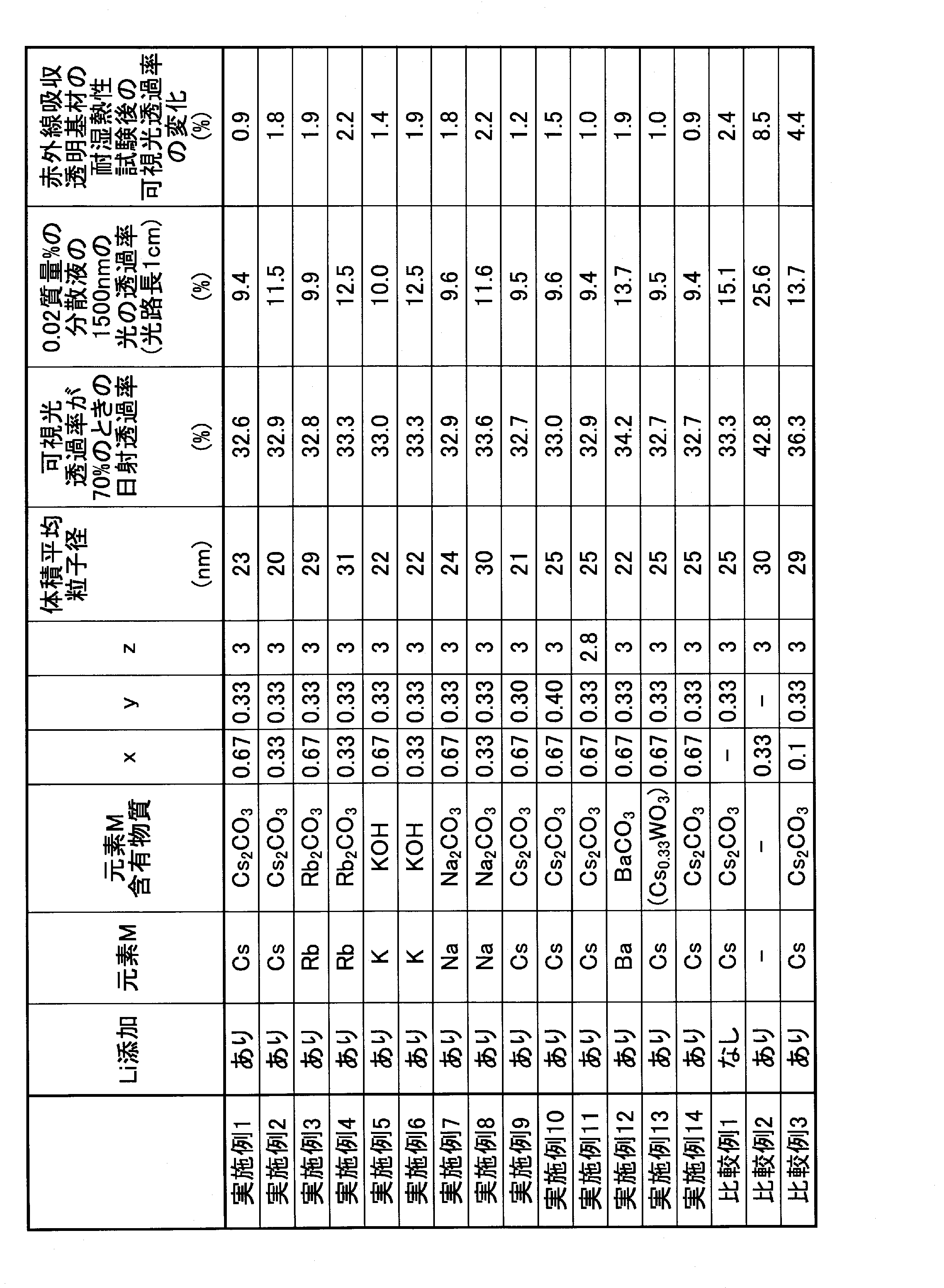
実施例1~14に係る熱線遮蔽粒子を用いた熱線遮蔽粒子分散液においては、比較例1の熱線遮蔽粒子を用いた熱線遮蔽粒子分散液と比較して、熱線遮蔽粒子の濃度が0.02質量%の分散液での1500nmの透過率が低くなっていることが確認できた。このため、実施例1~14は比較例1の熱線遮蔽粒子と比較して高い着色力を有することが確認された。
また、赤外線吸収透明基材に対して耐湿熱性の試験を行った前後の可視光透過率の変化が、実施例1~14では比較例1よりも小さいことが確認できた。係る結果から、実施例1~14の熱線遮蔽粒子を用いた赤外線吸収透明基材は、比較例1の熱線遮蔽粒子を用いた赤外線吸収透明基材と比較して高い耐候性が得られていることが確認された。
なお、可視光透過率が70%の時の日射透過率の値から赤外線吸収透明基材の遮熱特性を評価できるが、実施例1~14はいずれも比較例1とおおむね同等であり、遮熱特性を低下させることなく、比較例1よりも耐候性を向上できていることが確認できた。
比較例2においては、元素Mを含まず、リチウムのみを添加したことから、タングステン酸化物の結晶構造が六方晶ではなく立方晶となり、熱線遮蔽フィルムの遮熱特性が劣るものとなった。
比較例3においては、リチウムの添加量(モル比率)xが0.1と少なかったことから、六方晶の結晶構造や、結晶構造中におけるリチウムやセシウムの安定性が不十分であると考えられる。このため、熱線遮蔽粒子及び赤外線吸収透明基材の耐湿熱性が実施例1~14と比較して劣る結果になったと考えられる。
以上に熱線遮蔽粒子、熱線遮蔽粒子分散液、熱線遮蔽粒子分散体、熱線遮蔽粒子分散体合わせ透明基材、赤外線吸収透明基材、及び熱線遮蔽粒子の製造方法について、実施形態および実施例等で説明したが、本発明は上記実施形態および実施例等に限定されない。特許請求の範囲に記載された本発明の要旨の範囲内において、種々の変形、変更が可能である。
本出願は、2014年10月30日に日本国特許庁に出願された特願2014-221391号に基づく優先権を主張するものであり、特願2014-221391号の全内容を本国際出願に援用する。
Claims (21)
- 一般式LixMyWOzで表記され、六方晶の結晶構造を有する複合タングステン酸化物粒子であり、
前記一般式における元素Mが、リチウムを除くアルカリ金属、及びアルカリ土類金属から選択される、1種類以上の元素であり、
かつ、0.25≦x≦0.80、0.10≦y≦0.50、2.20≦z≦3.00である熱線遮蔽粒子。 - 前記元素Mがセシウム、ルビジウム、カリウム、ナトリウムから選択される1種類以上の元素である、請求項1に記載の熱線遮蔽粒子。
- 体積平均粒子径が1nm以上500nm以下である、請求項1または2に記載の熱線遮蔽粒子。
- 請求項1から3のいずれか一項に記載の熱線遮蔽粒子と、
水、有機溶媒、液状樹脂、液状プラスチック用可塑剤から選択された1種類以上を含有する液状媒体とを含む熱線遮蔽粒子分散液。 - 前記熱線遮蔽粒子の含有量が0.01質量%以上50質量%以下である請求項4に記載の熱線遮蔽粒子分散液。
- 請求項1から3のいずれか一項に記載の熱線遮蔽粒子と、
固体状のバインダーとを含む熱線遮蔽粒子分散体。 - 前記バインダーが少なくとも熱可塑性樹脂またはUV硬化性樹脂を含む、請求項6に記載の熱線遮蔽粒子分散体。
- 前記熱可塑性樹脂が、
ポリエチレンテレフタレート樹脂、ポリカーボネート樹脂、アクリル樹脂、スチレン樹脂、ポリアミド樹脂、ポリエチレン樹脂、塩化ビニル樹脂、オレフィン樹脂、エポキシ樹脂、ポリイミド樹脂、フッ素樹脂、エチレン・酢酸ビニル共重合体、ポリビニルアセタール樹脂の樹脂群から選択される1種類の樹脂、
または、前記樹脂群から選択される2種類以上の樹脂の混合物、
または、前記樹脂群から選択される2種類以上の樹脂の共重合体、のいずれかである請求項7に記載の熱線遮蔽粒子分散体。 - 前記熱線遮蔽粒子の含有量が0.001質量%以上80.0質量%以下である請求項6から8のいずれか一項に記載の熱線遮蔽粒子分散体。
- シート形状、ボード形状またはフィルム形状を有する請求項6から9のいずれか一項に記載の熱線遮蔽粒子分散体。
- 単位投影面積あたりの前記熱線遮蔽粒子の含有量が、0.04g/m2以上4.0g/m2以下である請求項6から10のいずれか一項に記載の熱線遮蔽粒子分散体。
- 複数枚の透明基材と、
請求項6から11のいずれか一項に記載の熱線遮蔽粒子分散体とを有し、
前記熱線遮蔽粒子分散体が、前記複数枚の透明基材の間に配置されている熱線遮蔽粒子分散体合わせ透明基材。 - 透明基材と、
前記透明基材の少なくとも一方の面上に配置された請求項1から3のいずれか一項に記載の熱線遮蔽粒子を含有するコーティング層とを有し、
前記透明基材は、透明樹脂基材、または透明ガラス基材である赤外線吸収透明基材。 - 前記コーティング層はさらにUV硬化性樹脂を含む請求項13に記載の赤外線吸収透明基材。
- 前記コーティング層の厚さが10μm以下である請求項13または14に記載の赤外線吸収透明基材。
- 前記透明基材が、ポリエステルフィルムである請求項13から15のいずれか一項に記載の赤外線吸収透明基材。
- 前記コーティング層の単位投影面積あたりの前記熱線遮蔽粒子の含有量が、0.04g/m2以上4.0g/m2以下である、請求項13から16のいずれか一項に記載の赤外線吸収透明基材。
- 請求項1から3のいずれか一項に記載の熱線遮蔽粒子を製造する熱線遮蔽粒子の製造方法であって、
リチウム含有物質と、元素M含有物質と、タングステン含有物質とを含む混合物に対して、不活性ガスと還元性ガスとの混合雰囲気中で熱処理を施す熱線遮蔽粒子の製造方法。 - 前記リチウム含有物質が炭酸リチウム、水酸化リチウムから選択される1種類以上であり、
前記元素M含有物質が、元素Mの炭酸塩、元素Mの水酸化物、元素Mの酸化物から選択される1種類以上であり、
前記タングステン含有物質が、金属タングステン、タングステン酸化物、タングステン酸、タングステン酸アンモニウムから選択される1種類以上であり、
前記還元性ガスが水素であり、
前記還元性ガスと前記不活性ガスとの混合雰囲気に占める前記還元性ガスの割合が、0.1体積%以上20体積%以下である、請求項18に記載の熱線遮蔽粒子の製造方法。 - 請求項1から3のいずれか一項に記載の熱線遮蔽粒子を製造する熱線遮蔽粒子の製造方法であって、
リチウム含有物質と、元素Mを含む複合タングステン酸化物とを含有する混合物に対して、不活性ガスと還元性ガスとの混合雰囲気中で熱処理を施す熱線遮蔽粒子の製造方法。 - 請求項1から3のいずれか一項に記載の熱線遮蔽粒子を製造する熱線遮蔽粒子の製造方法であって、
リチウム含有物質と、元素M含有物質と、タングステン含有物質とを含み、元素Mのタングステン元素に対するモル比率y1が0.01≦y1<0.25である第1原料混合物に対して、不活性ガスと還元性ガスとの混合雰囲気中で熱処理を施す第1熱処理工程と、
前記第1熱処理工程で得られた処理物に、元素M含有物質を添加、混合して第2原料混合物を調製する第2原料混合物調製工程と、
前記第2原料混合物に対して、不活性ガスと還元性ガスとの混合雰囲気中で熱処理を施す第2熱処理工程と、を有し、
前記第2原料混合物調製工程において添加する元素M含有物質と、前記第1原料混合物と、に含まれる元素Mの合計の、前記第1原料混合物に含まれるタングステン元素に対するモル比率y2が0.10≦y2≦0.50である熱線遮蔽粒子の製造方法。
Priority Applications (4)
| Application Number | Priority Date | Filing Date | Title |
|---|---|---|---|
| US15/522,024 US10787581B2 (en) | 2014-10-30 | 2015-10-13 | Heat ray shielding particles, heat ray shielding particle dispersion liquid, heat ray shielding particle dispersion, heat ray shielding particle dispersion laminated transparent base material, infrared ray absorbing transparent base material, and method of producing heat ray shielding particles |
| CN201580057485.0A CN107207943B (zh) | 2014-10-30 | 2015-10-13 | 热射线遮蔽粒子及其分散液、分散体、制造方法以及透明基材 |
| KR1020177010768A KR102116808B1 (ko) | 2014-10-30 | 2015-10-13 | 열선 차폐 입자, 열선 차폐 입자 분산액, 열선 차폐 입자 분산체, 열선 차폐 입자 분산체를 구비한 투명 기재, 적외선 흡수 투명 기재 및 열선 차폐 입자 제조방법 |
| EP15854781.0A EP3214148B1 (en) | 2014-10-30 | 2015-10-13 | Heat-ray-shielding particles |
Applications Claiming Priority (2)
| Application Number | Priority Date | Filing Date | Title |
|---|---|---|---|
| JP2014-221391 | 2014-10-30 | ||
| JP2014221391A JP6299559B2 (ja) | 2014-10-30 | 2014-10-30 | 熱線遮蔽粒子、熱線遮蔽粒子分散液、熱線遮蔽粒子分散体、熱線遮蔽粒子分散体合わせ透明基材、赤外線吸収透明基材、熱線遮蔽粒子の製造方法 |
Publications (1)
| Publication Number | Publication Date |
|---|---|
| WO2016067905A1 true WO2016067905A1 (ja) | 2016-05-06 |
Family
ID=55857246
Family Applications (1)
| Application Number | Title | Priority Date | Filing Date |
|---|---|---|---|
| PCT/JP2015/078885 Ceased WO2016067905A1 (ja) | 2014-10-30 | 2015-10-13 | 熱線遮蔽粒子、熱線遮蔽粒子分散液、熱線遮蔽粒子分散体、熱線遮蔽粒子分散体合わせ透明基材、赤外線吸収透明基材、熱線遮蔽粒子の製造方法 |
Country Status (7)
| Country | Link |
|---|---|
| US (1) | US10787581B2 (ja) |
| EP (1) | EP3214148B1 (ja) |
| JP (1) | JP6299559B2 (ja) |
| KR (1) | KR102116808B1 (ja) |
| CN (1) | CN107207943B (ja) |
| TW (1) | TWI681088B (ja) |
| WO (1) | WO2016067905A1 (ja) |
Cited By (2)
| Publication number | Priority date | Publication date | Assignee | Title |
|---|---|---|---|---|
| CN109071867A (zh) * | 2016-06-15 | 2018-12-21 | 沙特基础工业全球技术有限公司 | 红外线阻断组合物、其形成方法以及由其形成的红外层 |
| WO2021210593A1 (ja) * | 2020-04-13 | 2021-10-21 | 国立大学法人京都大学 | 赤外線センシングデバイス及びそれに用いる抵抗可変膜 |
Families Citing this family (13)
| Publication number | Priority date | Publication date | Assignee | Title |
|---|---|---|---|---|
| JP6686719B2 (ja) * | 2016-06-15 | 2020-04-22 | 住友金属鉱山株式会社 | 熱線遮蔽微粒子分散体、熱線遮蔽合わせ透明基材、およびそれらの製造方法 |
| JP6668185B2 (ja) * | 2016-07-05 | 2020-03-18 | 住友金属鉱山株式会社 | 複合タングステン酸化物の置換元素の選択方法、複合タングステン酸化物の製造方法 |
| US11345607B2 (en) | 2016-07-26 | 2022-05-31 | Sumitomo Metal Mining Co., Ltd. | Near-infrared absorbing fine particle dispersion liquid, near-infrared absorbing fine particle dispersion body, near-infrared absorbing transparent substrate, near-infrared absorbing laminated transparent substrate |
| TWI631079B (zh) * | 2017-03-14 | 2018-08-01 | 賽能有限公司 | 一種銣銫鎢青銅顆粒製造方法以及其組合物 |
| CN110997571A (zh) * | 2017-08-09 | 2020-04-10 | 住友金属矿山株式会社 | 电磁波吸收颗粒分散体、电磁波吸收用层叠透明基材 |
| CN111094490A (zh) * | 2017-09-14 | 2020-05-01 | 住友金属矿山株式会社 | 粘接剂层、近红外线吸收膜、夹层结构体、叠层体、粘接剂组合物及其制造方法 |
| US11578184B2 (en) | 2017-11-13 | 2023-02-14 | Sumitomo Metal Mining Co., Ltd. | Absorbing fine particle dispersion liquid and absorbing fine particles dispersion body having excellent long-term stability, and method for producing them |
| JP6911721B2 (ja) * | 2017-11-14 | 2021-07-28 | 住友金属鉱山株式会社 | 赤外線吸収体 |
| JP7225678B2 (ja) * | 2018-10-25 | 2023-02-21 | 住友金属鉱山株式会社 | セシウムタングステン酸化物焼結体及びその製造方法、セシウムタングステン酸化物ターゲット |
| US11359093B2 (en) | 2019-04-01 | 2022-06-14 | Microcosm Technology Co., Ltd. | Polyimide film and flexible display device cover substrate using the same |
| KR102036253B1 (ko) * | 2019-04-22 | 2019-10-24 | 황태경 | 비방사성 안정 동위원소를 이용한 친환경 열 차폐 필름 및 그 제조방법 |
| WO2022080420A1 (ja) * | 2020-10-14 | 2022-04-21 | 住友金属鉱山株式会社 | 近赤外線吸収粒子、近赤外線吸収粒子の製造方法、近赤外線吸収粒子分散体、近赤外線吸収積層体、近赤外線吸収透明基材 |
| JP7673403B2 (ja) * | 2020-12-24 | 2025-05-09 | 住友金属鉱山株式会社 | 熱線遮蔽樹脂シート材 |
Citations (3)
| Publication number | Priority date | Publication date | Assignee | Title |
|---|---|---|---|---|
| JP2011063493A (ja) * | 2009-09-18 | 2011-03-31 | Sumitomo Metal Mining Co Ltd | 近赤外線遮蔽材料微粒子分散体および近赤外線遮蔽体および近赤外線遮蔽材料分散体の製造方法 |
| JP2011063739A (ja) * | 2009-09-18 | 2011-03-31 | Sumitomo Metal Mining Co Ltd | 近赤外線遮蔽材料微粒子とその製造方法および近赤外線遮蔽材料微粒子分散体と近赤外線遮蔽体 |
| JP2012072402A (ja) * | 2011-09-26 | 2012-04-12 | Sumitomo Metal Mining Co Ltd | 赤外線遮蔽材料微粒子分散体、赤外線遮蔽体、及び赤外線遮蔽材料微粒子の製造方法、並びに赤外線遮蔽材料微粒子 |
Family Cites Families (12)
| Publication number | Priority date | Publication date | Assignee | Title |
|---|---|---|---|---|
| JPH02136230A (ja) | 1988-11-16 | 1990-05-24 | Takiron Co Ltd | 赤外線吸収性合成樹脂成型品 |
| JP3154645B2 (ja) | 1995-01-23 | 2001-04-09 | セントラル硝子株式会社 | 自動車用合せガラス |
| JP4058822B2 (ja) | 1997-09-30 | 2008-03-12 | 住友金属鉱山株式会社 | 選択透過膜用塗布液、選択透過膜および選択透過多層膜 |
| US6060154A (en) | 1997-09-30 | 2000-05-09 | Sumitomo Metal Mining Co., Ltd. | Coating liquid for selective permeable membrane, selective permeable membrane and selective permeable multilayered membrane |
| KR100509507B1 (ko) | 2003-10-20 | 2005-08-22 | 삼성전자주식회사 | 전자사진방식 화상형성장치의 토너 카트리지 |
| EP1676890B1 (en) | 2003-10-20 | 2019-06-26 | Sumitomo Metal Mining Co., Ltd. | Infrared shielding material microparticle dispersion, infrared shield, process for producing infrared shielding material microparticle, and infrared shielding material microparticle |
| CN102965049A (zh) * | 2007-11-05 | 2013-03-13 | 巴斯夫欧洲公司 | 用于提高近红外辐射的热输入量的氧化钨 |
| JP3154457U (ja) | 2008-08-29 | 2009-10-22 | 洋二 早川 | 水環境電池を利用した噴霧装置 |
| US8853314B2 (en) * | 2008-10-23 | 2014-10-07 | Datalase Ltd. | Heat absorbing additives |
| CN102471090B (zh) | 2009-07-07 | 2015-11-25 | 巴斯夫欧洲公司 | 钾铯钨青铜颗粒 |
| JP2011063484A (ja) * | 2009-09-18 | 2011-03-31 | Sumitomo Metal Mining Co Ltd | 近赤外線遮蔽材料微粒子とその製造方法および近赤外線遮蔽材料微粒子分散体と近赤外線遮蔽体 |
| JP2011063741A (ja) * | 2009-09-18 | 2011-03-31 | Sumitomo Metal Mining Co Ltd | 熱線遮蔽樹脂シート材と熱線遮蔽樹脂シート材積層体およびこれ等を用いた建築構造体 |
-
2014
- 2014-10-30 JP JP2014221391A patent/JP6299559B2/ja active Active
-
2015
- 2015-10-13 EP EP15854781.0A patent/EP3214148B1/en active Active
- 2015-10-13 US US15/522,024 patent/US10787581B2/en active Active
- 2015-10-13 KR KR1020177010768A patent/KR102116808B1/ko active Active
- 2015-10-13 WO PCT/JP2015/078885 patent/WO2016067905A1/ja not_active Ceased
- 2015-10-13 CN CN201580057485.0A patent/CN107207943B/zh active Active
- 2015-10-28 TW TW104135390A patent/TWI681088B/zh active
Patent Citations (3)
| Publication number | Priority date | Publication date | Assignee | Title |
|---|---|---|---|---|
| JP2011063493A (ja) * | 2009-09-18 | 2011-03-31 | Sumitomo Metal Mining Co Ltd | 近赤外線遮蔽材料微粒子分散体および近赤外線遮蔽体および近赤外線遮蔽材料分散体の製造方法 |
| JP2011063739A (ja) * | 2009-09-18 | 2011-03-31 | Sumitomo Metal Mining Co Ltd | 近赤外線遮蔽材料微粒子とその製造方法および近赤外線遮蔽材料微粒子分散体と近赤外線遮蔽体 |
| JP2012072402A (ja) * | 2011-09-26 | 2012-04-12 | Sumitomo Metal Mining Co Ltd | 赤外線遮蔽材料微粒子分散体、赤外線遮蔽体、及び赤外線遮蔽材料微粒子の製造方法、並びに赤外線遮蔽材料微粒子 |
Non-Patent Citations (1)
| Title |
|---|
| See also references of EP3214148A4 * |
Cited By (6)
| Publication number | Priority date | Publication date | Assignee | Title |
|---|---|---|---|---|
| CN109071867A (zh) * | 2016-06-15 | 2018-12-21 | 沙特基础工业全球技术有限公司 | 红外线阻断组合物、其形成方法以及由其形成的红外层 |
| EP3472235A1 (en) * | 2016-06-15 | 2019-04-24 | SABIC Global Technologies B.V. | Infrared blocking composition, methods of forming, and the infrared layer formed therefrom |
| WO2021210593A1 (ja) * | 2020-04-13 | 2021-10-21 | 国立大学法人京都大学 | 赤外線センシングデバイス及びそれに用いる抵抗可変膜 |
| JPWO2021210593A1 (ja) * | 2020-04-13 | 2021-10-21 | ||
| US12276550B2 (en) | 2020-04-13 | 2025-04-15 | Kyoto University | Infrared sensing device and variable resistance film included in the same |
| JP7837020B2 (ja) | 2020-04-13 | 2026-03-30 | 国立大学法人京都大学 | 赤外線センシングデバイス及びそれに用いる抵抗可変膜 |
Also Published As
| Publication number | Publication date |
|---|---|
| CN107207943A (zh) | 2017-09-26 |
| TW201631226A (zh) | 2016-09-01 |
| US20170334735A1 (en) | 2017-11-23 |
| CN107207943B (zh) | 2019-03-15 |
| EP3214148B1 (en) | 2019-09-18 |
| TWI681088B (zh) | 2020-01-01 |
| JP2016088960A (ja) | 2016-05-23 |
| KR102116808B1 (ko) | 2020-06-01 |
| EP3214148A4 (en) | 2018-04-04 |
| KR20170064536A (ko) | 2017-06-09 |
| US10787581B2 (en) | 2020-09-29 |
| JP6299559B2 (ja) | 2018-03-28 |
| EP3214148A1 (en) | 2017-09-06 |
Similar Documents
| Publication | Publication Date | Title |
|---|---|---|
| JP6299559B2 (ja) | 熱線遮蔽粒子、熱線遮蔽粒子分散液、熱線遮蔽粒子分散体、熱線遮蔽粒子分散体合わせ透明基材、赤外線吸収透明基材、熱線遮蔽粒子の製造方法 | |
| US11345607B2 (en) | Near-infrared absorbing fine particle dispersion liquid, near-infrared absorbing fine particle dispersion body, near-infrared absorbing transparent substrate, near-infrared absorbing laminated transparent substrate | |
| JP6686719B2 (ja) | 熱線遮蔽微粒子分散体、熱線遮蔽合わせ透明基材、およびそれらの製造方法 | |
| WO2016010156A1 (ja) | 熱線遮蔽微粒子、熱線遮蔽微粒子分散液、熱線遮蔽フィルム、熱線遮蔽ガラス、熱線遮蔽分散体および熱線遮蔽合わせ透明基材 | |
| WO2017094909A1 (ja) | 熱線遮蔽微粒子、熱線遮蔽微粒子分散液、熱線遮蔽フィルム、熱線遮蔽ガラス、熱線遮蔽分散体、および、熱線遮蔽合わせ透明基材 | |
| WO2016031969A1 (ja) | 六ホウ化物微粒子の集合体、六ホウ化物微粒子分散液、六ホウ化物微粒子分散体、六ホウ化物微粒子分散体合わせ透明基材、赤外線吸収フィルムおよび赤外線吸収ガラス | |
| JP6613674B2 (ja) | 熱線遮蔽微粒子および熱線遮蔽微粒子分散液 | |
| JP6879127B2 (ja) | 熱線遮蔽粒子、熱線遮蔽粒子の製造方法、熱線遮蔽粒子分散液、熱線遮蔽粒子分散液の製造方法、熱線遮蔽粒子分散体、熱線遮蔽合わせ透明基材、熱線遮蔽透明基材 | |
| KR102553348B1 (ko) | 적외선 흡수 미립자 및 이를 사용한 분산액, 분산체, 적층된 투명 기재, 필름, 유리, 및 이의 제조 방법 | |
| TWI705099B (zh) | 金屬微粒子之集合體、金屬微粒子分散液、熱射線遮蔽薄膜、熱射線遮蔽玻璃、熱射線遮蔽微粒子分散體及熱射線遮蔽夾層透明基材 | |
| JP7472699B2 (ja) | 赤外線吸収微粒子分散液、赤外線吸収微粒子分散体および赤外線吸収透明基材 | |
| JP6606898B2 (ja) | 熱線遮蔽分散体および熱線遮蔽合わせ透明基材 | |
| TWI666352B (zh) | 熱射線遮蔽微粒子、熱射線遮蔽微粒子分散液、熱射線遮蔽薄膜、熱射線遮蔽玻璃、熱射線遮蔽微粒子分散體及熱射線遮蔽用夾層透明基材 | |
| JP7024608B2 (ja) | 近赤外線吸収微粒子分散液とその製造方法 | |
| BR112018011273B1 (pt) | Método para produção de partículas finas de óxido de tungstênio compósito, líquido de dispersão de partículas finas, película ou vidro, corpo de dispersão de partículas finas, e, substrato transparente laminado de blindagem contra raios térmicos |
Legal Events
| Date | Code | Title | Description |
|---|---|---|---|
| 121 | Ep: the epo has been informed by wipo that ep was designated in this application |
Ref document number: 15854781 Country of ref document: EP Kind code of ref document: A1 |
|
| ENP | Entry into the national phase |
Ref document number: 20177010768 Country of ref document: KR Kind code of ref document: A |
|
| REEP | Request for entry into the european phase |
Ref document number: 2015854781 Country of ref document: EP |
|
| NENP | Non-entry into the national phase |
Ref country code: DE |