WO2016067958A1 - 電気回路遮断装置 - Google Patents
電気回路遮断装置 Download PDFInfo
- Publication number
- WO2016067958A1 WO2016067958A1 PCT/JP2015/079489 JP2015079489W WO2016067958A1 WO 2016067958 A1 WO2016067958 A1 WO 2016067958A1 JP 2015079489 W JP2015079489 W JP 2015079489W WO 2016067958 A1 WO2016067958 A1 WO 2016067958A1
- Authority
- WO
- WIPO (PCT)
- Prior art keywords
- housing
- electric circuit
- projectile
- cylinder
- circuit breaker
- Prior art date
- Legal status (The legal status is an assumption and is not a legal conclusion. Google has not performed a legal analysis and makes no representation as to the accuracy of the status listed.)
- Ceased
Links
Images


Classifications
-
- H—ELECTRICITY
- H01—ELECTRIC ELEMENTS
- H01H—ELECTRIC SWITCHES; RELAYS; SELECTORS; EMERGENCY PROTECTIVE DEVICES
- H01H39/00—Switching devices actuated by an explosion produced within the device and initiated by an electric current
- H01H39/006—Opening by severing a conductor
-
- H—ELECTRICITY
- H01—ELECTRIC ELEMENTS
- H01H—ELECTRIC SWITCHES; RELAYS; SELECTORS; EMERGENCY PROTECTIVE DEVICES
- H01H39/00—Switching devices actuated by an explosion produced within the device and initiated by an electric current
- H01H2039/008—Switching devices actuated by an explosion produced within the device and initiated by an electric current using the switch for a battery cutoff
Definitions
- the present invention relates to an electric circuit breaker that can be used for an electric circuit of an automobile or a home appliance.
- An electric circuit interrupting device that prevents major damage by blocking an electric circuit when an electric circuit itself such as an automobile or a household appliance is abnormal or an entire system including the electric circuit is used.
- the electric circuit breaker there are known ones in which an igniter, a projectile (piston), a conductor and the like are accommodated in a housing (US-A No. 2005/0083164, US-A No. 2005/0083165, US). -A No. 2012/0234162, JP-A No. H11-2332979, JP-A No. 2014-49300).
- JP-A No. In 2014-49300, the case 30 is formed of a material (for example, a resin material) having electrical insulation and high strength (paragraph number 0034).
- the present invention relates to an igniter and a synthetic resin in order from the first end side of the housing in the axial direction in a cylindrical space penetrating from the first end to the second end of the housing made of synthetic resin.
- a projecting body comprising: a conductor piece for forming a part of an electric circuit; and an insulating space for receiving a cut portion of the conductor piece between the second end of the housing and the conductor piece.
- An electric circuit breaker having The conductor piece is a plate piece composed of a connecting portion on both end sides and a cutting portion of an intermediate portion, and the surface of the cutting portion is arranged orthogonal to the axial direction of the housing, The projectile is arranged so as to face the cut surface of the conductor piece in the housing axial direction, An electric circuit breaker is provided in which a cylinder made of metal for reinforcing the housing is disposed between the projectile and the inner wall surface of the housing.
- FIG. 1 is an axial sectional view of an electric circuit breaker according to the present invention.
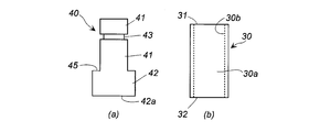
- 2A is a plan view of a projectile used in the electric circuit breaker of FIG. 1 in FIG. 2A
- FIG. 2B is a plan view of a cylinder used in the electric circuit breaker of FIG.
- FIG. 3 is an explanatory diagram of an assembling method of the electric circuit breaker according to the present invention.
- the present invention provides an electric circuit breaker capable of reducing the overall size by reducing the thickness of the housing while maintaining the required strength.
- the electric circuit breaker of the present invention can be used by attaching to various electric circuits such as automobile batteries (lithium ion batteries, etc.), home appliances, etc., and can break the electric circuit when an abnormality occurs in the electric circuit. It is.
- the electric circuit breaker of the present invention is characterized in that a cylinder is used as a member for reinforcing the housing.
- the housing is made of synthetic resin, and the outer shape is appropriately determined according to the attachment site.
- the housing is of a shape, structure, and size that can accommodate and attach components such as an igniter, projectile, cylinder, and conductor piece.
- the igniter is not only an igniter used in a known electric circuit breaker, but also an igniter for a gas generator used in an automobile airbag device.
- the igniter is provided with an igniting portion including an igniting agent and a conductive pin for energizing. When operating, an igniter burns the igniting agent by energizing from an external power source, and combustion products such as combustion gas and flame Is generated.
- the projectile receives the pressure of the combustion products generated by the operation of the igniter, moves in the housing in the axial direction, cuts the conductor pieces, and interrupts the electric circuit.
- the tip of the projectile is US-A No. 2005/0083164, US-A No. 2005/0083165 may be of the arrowhead shape indicated by 34 in FIG. A flat surface such as the piston 6 in FIG. 1 of 2012/0234162 may be used.
- the projectile can be made of the same synthetic resin as the housing.
- the same conductor piece as that used in a known electric circuit breaker can be used.
- the conductor piece is a plate piece composed of a connecting portion at both ends and a cut portion at an intermediate portion, and forms a part of the electric circuit when attached to the electric circuit.
- the shape of the conductor piece is a shape corresponding to the shape and structure of the attachment portion with respect to the housing.
- a cylinder made of metal for reinforcing the housing is disposed between the projectile and the inner wall surface of the housing.
- a cylinder made of stainless steel, iron, or the like can be used.
- the inner wall surface of the housing and the outer peripheral surface of the cylinder are preferably in contact with each other.
- the inner peripheral surface of the cylinder and the outer peripheral surface of the projectile may be in contact with each other, but it is preferable that a slight gap is formed in order to facilitate movement during operation.
- the cross-sectional shape in the width direction of the cylinder and the cross-sectional shape of the projectile are preferably the same, but may be partially different.
- an igniter, a cylinder, and a projectile are sequentially inserted into the cylindrical space of the housing from the second end side, and after attaching a conductor piece, a box-shaped stopper with one side opened is fitted. And fix the conductor piece. At this time, the internal space of the box-shaped stopper becomes an insulating space.
- the igniter when activated, the projectile moves in the axial direction, and the tip of the projectile collides with the cut portion of the conductor piece to cut the cut portion, and then the tip and the cut piece. Enters the insulation space. By cutting the cutting portion in this way, electrical disconnection occurs and the electric circuit is interrupted.
- the apparatus of the present invention uses a cylinder, the following effects can be obtained.
- First effect By reinforcing the housing using a cylinder made of metal, the thickness of the housing can be reduced, so that the device itself can be reduced in size.
- Second effect The combustion product generated by the operation of the igniter passes through the cylinder and collides with the projectile, so that the inner wall surface of the housing is not directly exposed to the heat and pressure of the combustion product. For this reason, the thickness of the housing can be reduced, and it can contribute to the miniaturization of the device itself together with the first effect.
- the cylinder serves as a passage for the combustion products generated by the operation of the igniter, all of the combustion products can collide with the projectile and also function as a guide portion when the projectile moves.
- the electric circuit breaker of the present invention is
- the projectile has a tip enlarged portion and a rod portion having a smaller outer diameter than the tip enlarged portion
- the cylinder has the first end opening side positioned on the igniter side, and the opposite second end opening side contacts the stepped surface between the enlarged diameter portion and the rod portion, and surrounds the rod portion. Those arranged in this way are preferred.
- the projectile has a tip diameter increasing portion and a rod portion having an outer diameter smaller than that of the tip diameter increasing portion.
- the enlarged diameter portion of the tip collides with and breaks the conductor piece, so that the projectile can be reduced in weight while maintaining the breaking strength against the conductor piece (fourth effect).
- the second end opening of the cylinder is in contact with the step surface at the boundary between the enlarged diameter portion and the rod portion, and the cylinder is restricted from moving to the conductor piece before operation, The contact of the conductor pieces is prevented.
- the electric circuit breaker of the present invention is
- the projectile has a tip enlarged portion and a rod portion having a smaller outer diameter than the tip enlarged portion
- the igniter has a resin part in which a part of the igniter main body is surrounded by a resin, and the ignition part protrudes from the resin part
- the cylinder has a first end opening side in contact with a resin portion of the igniter, and an opposite second end opening side in contact with a stepped surface between the enlarged diameter portion and the rod portion. What is arrange
- positioned so that the ignition part and the said rod part of a vessel may be enclosed is preferable.
- the cylinder Since the cylinder is supported in the axial direction by the step surface of the igniter and the projecting part, the cylinder can be easily attached to the housing. At this time, the projectile can be installed in the cylinder. In addition, since the cylinder surrounds the ignition part of the igniter and the rod part of the projectile, the second action effect and the third action effect are enhanced. In addition, since the second end opening of the cylinder is in contact with the step surface at the boundary between the enlarged diameter portion and the rod portion, and the cylinder is restricted from moving to the conductor piece before operation, The contact of the conductor pieces is prevented.
- the electric circuit breaker of the present invention is
- the projectile has a tip enlarged portion and a rod portion having a smaller outer diameter than the tip enlarged portion,
- the cross-sectional shape in the width direction of the tip diameter-enlarged portion is square or circular, and the cross-sectional shape in the width direction of the rod portion is circular, It is preferable that the cylinder has a circular cross-sectional shape in the width direction.
- the cross-sectional shape in the width direction of the tip enlarged-diameter portion is a quadrangle because the cut portion of the conductor piece is easily cut. Since the cross-sectional shape in the width direction of the rod portion and the cross-sectional shape in the width direction of the cylinder are both circular, the projectile can be easily moved.
- the electric circuit breaker of the present invention is
- the projectile has a tip enlarged portion and a rod portion having a smaller outer diameter than the tip enlarged portion,
- the rod portion of the projectile has a constricted portion into which an O-ring is fitted, and the O-ring is brought into contact with the inner peripheral surface of the cylinder, and the outer surface of the rod portion and the inner surface of the cylinder Are not in contact with each other.
- the projectile rod part comes into contact with the inner surface of the cylinder only at the O-ring, so that the projectile is easily moved during operation, and the combustion products generated from the igniter are transferred between the cylinder and the rod part. It is prevented from escaping through. For this reason, the 2nd operation effect and the 3rd operation effect are strengthened.
- the electric circuit breaker of the present invention is reinforced by placing a cylinder made of metal in a housing made of synthetic resin, the thickness of the housing is reduced while maintaining the required strength, and the entire apparatus Can be miniaturized.
- the electric circuit breaker 1 of the present invention is novel in that a cylinder 30 is used, and other parts are also used in known electric circuit breakers. However, since the cylinder 30 is new, the arrangement relationship between the cylinder 30 and other parts is new.
- the housing 10 made of synthetic resin has a cylindrical space 13 that penetrates from the first end 11 to the second end 12. On the first end portion 11 side, a connector fitting portion 15 connected with a power source and a lead wire in use is attached.
- an igniter 20 In the cylindrical space 13 of the housing 10, an igniter 20, a projectile 40 made of synthetic resin, and a conductor piece 50 are arranged in the axial direction from the first end 11 side.
- the igniter 20 has a resin part 22 in which a part of an igniter main body having an ignition part 21 and a conductive pin 23 is surrounded by a resin, and the ignition part 21 protrudes from the resin part 22.
- the projectile 40 shown in FIG. 1 and FIG. 2A has a rod portion 41 and a tip diameter increasing portion 42 formed at the tip of the rod portion 41. Since the outer diameter of the tip enlarged portion 42 is larger than the outer diameter of the rod portion 41, an annular step surface 45 is formed at the boundary between the rod portion 41 and the tip enlarged portion 42.
- the cross-sectional shape in the width direction of the rod portion 41 is a circle, and the cross-sectional shape in the width direction of the tip enlarged diameter portion 42 is a quadrangle (preferably a square) or a circle.
- the rod portion 41 has a constricted portion 43 whose outer diameter is partially reduced, and an O-ring 44 made of rubber (for example, silicone rubber) or synthetic resin is fitted into the constricted portion 43.
- the outer diameter of the rod portion 41 and the outer diameter of the portion where the O-ring 44 is fitted are slightly larger than the outer diameter of the portion where the O-ring 44 is fitted.
- a cylinder 30 shown in FIGS. 1 and 2 (b) is for reinforcing the housing 10, and is made of a metal such as stainless steel or iron.
- the thickness of the cylinder 30 varies depending on the size of the apparatus 1, but is preferably in the range of about 0.5 to 3 mm in order to obtain the first to third effects described above.
- the cylinder 30 is arranged such that the outer surface 30 a is in contact with the inner wall surface 13 a of the cylindrical space 13.
- the cylinder 30 is in contact with the resin portion 22 of the igniter 20 on the first end opening 31 side, and is in contact with the annular step surface 45 of the projectile 40 on the opposite second end opening 32 side.
- the cylinder 30 surrounds the ignition part 21 of the igniter 20 and the rod part 41 of the projectile 40.
- the O-ring 44 fitted in the constricted portion 43 of the projectile 40 is in contact with the inner peripheral surface 30b of the cylinder 30, but the outer surface of the rod portion 41 and the inner surface 30b of the cylinder 30 are not in contact. .
- the cylinder 30 is fixed so as not to move in the axial direction by being press-fitted into the cylindrical space 13.
- a claw portion is formed on the outer surface 30a of the cylinder 30, and a recess corresponding to the claw portion is formed on the inner wall surface of the housing 10 (inner wall surface 13a of the cylindrical space 13) opposed in the radial direction.
- the claw portion can be fitted into the recess, and the cylinder 30 can be fixed so as not to move in the axial direction.
- the conductor piece 50 is for forming a part of the electric circuit when the device 1 is attached to the electric circuit.
- the conductor piece 50 is a plate piece including a first connection portion 51 and a second connection portion 52 on both end sides, and a cut portion 53 at an intermediate portion.
- the holes 51a of the two first connection portions 51 and the holes 52a of the second connection portion 52 are for connecting to other conductors (for example, lead wires) in the electric circuit.
- the conductor piece 50 shown in FIG. 1 is formed so that the surface of the cutting portion 53 and the surfaces of the first connecting portion 51 and the second connecting portion 52 are orthogonal to each other. 51 and the surface of the 2nd connection part 52 may form the same surface.
- the conductor piece 50 has a thickness of a portion from the cut portion 53 of the first connection portion 51 and a portion from the cut portion 53 of the second connection portion 52 depending on the shape and structure of the mounting portion 55 of the housing 10. It may be deformed in the direction.
- the conductor piece 50 is disposed such that the surface of the cutting portion 53 is orthogonal to the axial direction of the housing 10.
- the surface of the cutting part 53 of the conductor piece 50 faces the tip surface 42 a of the tip diameter-enlarging part 42 of the projectile 40.
- the surface of the cutting portion 53 and the tip surface 42 a are in contact with each other, but may be opposed to each other with a gap.
- the cross-sectional shape in the width direction of the tip enlarged diameter portion 42 of the projectile 40 is a square
- a box-shaped stopper 60 having an opening on one side is disposed so that the opening side is on the conductor piece 50 side.
- the box-shaped stopper 60 is made of a synthetic resin and has an insulating space 61 inside.
- the housing 10 has a cylindrical space 13, and further has a mounting portion 55 for mounting a conductor piece 50, which is a known component, and a thickness direction for fitting a box-shaped stopper 60, which is a known component. And has an opening 65 penetrating through.
- the shape and structure of the attachment portion 55 correspond to the shape of the conductor piece 50, and the shape and size of the opening 65 correspond to the shape and size of the box-shaped stopper 60.
- the igniter 20 is inserted into the cylindrical space 13 from the second end 12 side of the housing.
- the cylinder 30 is inserted into the cylindrical space 13 in the same manner as the igniter 20. At this time, the cylinder 30 is inserted until the first end opening 31 side contacts the resin portion 22 of the igniter 20.
- the projectile 40 is inserted into the cylindrical space 13 from the rod part 41 side. At this time, the rod portion 41 enters the previously inserted cylinder 30 and is inserted until the annular step surface 45 of the tip diameter-expanding portion 42 contacts the second opening 32 of the cylinder 30.
- the conductor piece 50 is attached to the attachment portion 55 of the housing 10.
- the box-shaped stopper 60 is fitted into the opening 65 so that the opening surface is on the cutting part 53 side.
- the opening 65 is closed by the side surface of the box-shaped stopper 60
- the opening of the cylindrical space 13 on the second end 12 side of the housing is closed by the bottom surface of the box-shaped stopper 60.
- a claw portion is formed on the side surface of the stopper 60, and a concave portion corresponding to the claw portion is formed on the surface of the opening 65, and the stopper 60 is fixed by fitting the claw portion into the concave portion at the time of attachment. It may be.
- the thickness of the housing 10 is reduced by the first effect described above. And the size of the device itself can be reduced.
- the electric circuit breaker 1 shown in FIG. 1 can reduce the width and thickness of the housing 10 by about 30 to 80% compared to the case where the cylinder 30 is not used.
- the electric circuit breaker 1 shown in FIG. 1 can be combined with a sensor for detecting an abnormal current, for example, so as to automatically start when an abnormal current flows in the electric circuit. It can also be made to operate.
- the conductor piece 50 is connected to the lead wire constituting the electric circuit in the hole 51 a of the first connection portion 51 and the hole 52 a of the second connection portion 52.
- the igniter 20 is activated and combustion products are generated from the ignition unit 21. Since the ignition unit 21 is surrounded on the first end opening 31 side of the cylinder 30, the generated combustion products travel straight through the cylinder 30 and collide with the rod portion 41 of the projectile 40. In this way, the high-temperature combustion product moves in the metal cylinder 30 and collides with the projectile 40, so that the inner wall surface 13a of the cylindrical space 13 is not directly exposed to the heat and pressure of the combustion product. Therefore, the thickness of the housing 10 can be reduced also by the second effect, and the device itself can be downsized.
- the projectile 40 that has received pressure from the combustion product moves in the axial direction due to the third effect described above, and cuts the cutting portion 53 of the conductor piece 50 by the tip enlarged-diameter portion 42. After that, the cut pieces of the tip enlarged diameter portion 42 and the cutting portion 53 move into the insulating space 61 and are electrically insulated. By this operation, the first connection portion 51 and the second connection portion 52 at both ends of the conductor piece 50 are electrically disconnected, so that the electric circuit in which the device 1 is disposed is interrupted.
- the electric circuit breaker of the present invention can be arranged in various electric circuits, and is particularly suitable for electric circuits including automobile batteries (for example, lithium ion batteries) and electric circuits for home appliances.
Landscapes
- Fuses (AREA)
- Air Bags (AREA)
- Circuit Breakers (AREA)
Abstract
本発明は、 合成樹脂からなるハウジングの第1端部から第2端部まで貫通した筒状空間内において、前記ハウジングの第1端部側から軸方向に順に点火器、合成樹脂からなる発射体、電気回路の一部を形成させるための導体片が配置され、前記ハウジングの第2端部と前記導体片の間には、前記導体片の切断部分を受けるための絶縁空間を有している電気回路遮断装置であって、 前記導体片が、両端側の接続部と中間部分の切断部からなる板片であり、前記切断部の面が前記ハウジングの軸方向に直交して配置されているものであり、 前記発射体が、前記導体片の切断部の面とハウジング軸方向に対向して配置されているものであり、 前記発射体と前記ハウジング内壁面の間には、前記ハウジングを補強するための金属からなるシリンダーが配置されている、電気回路遮断装置である。
Description
本発明は、自動車や家庭電化製品などの電気回路に使用することができる電気回路遮断装置に関する。
背景技術
自動車や家庭電化製品などの電気回路自体や前記電気回路を含むシステム全体の異常時などにおいて、電気回路を遮断することで大きな被害を未然に防止する電気回路遮断装置が使用されている。
電気回路遮断装置は、ハウジング内に点火器、発射体(ピストン)、導体などが収容されたものが知られている(US-A No. 2005/0083164、US-A No. 2005/0083165、US-A No. 2012/0234162、JP-A No. H11-232979、 JP-A No. 2014-49300)。
自動車や家庭電化製品などの電気回路自体や前記電気回路を含むシステム全体の異常時などにおいて、電気回路を遮断することで大きな被害を未然に防止する電気回路遮断装置が使用されている。
電気回路遮断装置は、ハウジング内に点火器、発射体(ピストン)、導体などが収容されたものが知られている(US-A No. 2005/0083164、US-A No. 2005/0083165、US-A No. 2012/0234162、JP-A No. H11-232979、 JP-A No. 2014-49300)。
US-A No. 2005/0083164、US-A No. 2005/0083165、では、ハウジングの材質として、金属、セラミックス、ポリマーが例示されており、特定のポリマーが好ましいと記載されている(US-A No. 2005/0083164の2~3頁、US-A No. 2005/0083165の2頁)。
JP-A No. H11-232979では、ケーシング13はステンレスからなるものである(段落番号0011)。
JP-A No. 2014-49300では、ケース30は、電気絶縁性を有し、かつ強度の高い材料( 例えば樹脂材料)によって形成されている(段落番号0034)。
JP-A No. H11-232979では、ケーシング13はステンレスからなるものである(段落番号0011)。
JP-A No. 2014-49300では、ケース30は、電気絶縁性を有し、かつ強度の高い材料( 例えば樹脂材料)によって形成されている(段落番号0034)。
本発明の開示
本発明は、合成樹脂からなるハウジングの第1端部から第2端部まで貫通した筒状空間内において、前記ハウジングの第1端部側から軸方向に順に点火器、合成樹脂からなる発射体、電気回路の一部を形成させるための導体片が配置され、前記ハウジングの第2端部と前記導体片の間には、前記導体片の切断部分を受けるための絶縁空間を有している電気回路遮断装置であって、
前記導体片が、両端側の接続部と中間部分の切断部からなる板片であり、前記切断部の面が前記ハウジングの軸方向に直交して配置されているものであり、
前記発射体が、前記導体片の切断部の面とハウジング軸方向に対向して配置されているものであり、
前記発射体と前記ハウジング内壁面の間には、前記ハウジングを補強するための金属からなるシリンダーが配置されている、電気回路遮断装置を提供する。
本発明は、合成樹脂からなるハウジングの第1端部から第2端部まで貫通した筒状空間内において、前記ハウジングの第1端部側から軸方向に順に点火器、合成樹脂からなる発射体、電気回路の一部を形成させるための導体片が配置され、前記ハウジングの第2端部と前記導体片の間には、前記導体片の切断部分を受けるための絶縁空間を有している電気回路遮断装置であって、
前記導体片が、両端側の接続部と中間部分の切断部からなる板片であり、前記切断部の面が前記ハウジングの軸方向に直交して配置されているものであり、
前記発射体が、前記導体片の切断部の面とハウジング軸方向に対向して配置されているものであり、
前記発射体と前記ハウジング内壁面の間には、前記ハウジングを補強するための金属からなるシリンダーが配置されている、電気回路遮断装置を提供する。
本発明は、以下の詳細な説明と添付された図面により、さらに完全に理解されるものであるが、これらはただ説明のため付されるものであり、本発明を制限するものではない。
本発明の詳細な説明
ポリマー材料(樹脂材料)を使用したときは、例えば、US-A No. 2005/0083164、US-A No. 2005/0083165、JP-A No. 2014-49300のそれぞれの図1などからも理解できるとおり、必要な強度を付与する点から、ハウジング(ケーシング)を厚肉にする必要がある。
JP-A No. H11-232979のようにステンレスのケーシング13を使用したときは、質量の増加が大きくなるほか、絶縁ケース14を組み合わせて配置する必要があるため、構造および組み立てが複雑になる。
ポリマー材料(樹脂材料)を使用したときは、例えば、US-A No. 2005/0083164、US-A No. 2005/0083165、JP-A No. 2014-49300のそれぞれの図1などからも理解できるとおり、必要な強度を付与する点から、ハウジング(ケーシング)を厚肉にする必要がある。
JP-A No. H11-232979のようにステンレスのケーシング13を使用したときは、質量の増加が大きくなるほか、絶縁ケース14を組み合わせて配置する必要があるため、構造および組み立てが複雑になる。
自動車用のバッテリー、例えば、リチウムイオンバッテリーなどに電流遮断装置を使用するときは、できるだけハウジングを薄肉化することで全体を小型化することが望ましい。
本発明は、必要な強度を維持したままでハウジングを薄肉化して、全体を小型化することができる電気回路遮断装置を提供する。
本発明は、必要な強度を維持したままでハウジングを薄肉化して、全体を小型化することができる電気回路遮断装置を提供する。
本発明の電気回路遮断装置は、自動車のバッテリー(リチウムイオンバッテリーなど)、家庭電化製品などの様々な電気回路に取り付けて使用して、電気回路に異常が生じたときには、電気回路を遮断できるものである。
本発明の電気回路遮断装置は、ハウジングを補強するための部材としてシリンダーを使用したことが特徴である。
本発明の電気回路遮断装置は、ハウジングを補強するための部材としてシリンダーを使用したことが特徴である。
ハウジングは、合成樹脂からなるものであり、外形は取り付け部位に応じて適宜決定されるものである。
ハウジングは、点火器、発射体、シリンダー、導体片などの部品を収容したり、取り付けたりすることができる形状、構造および大きさのものである。
ハウジングは、点火器、発射体、シリンダー、導体片などの部品を収容したり、取り付けたりすることができる形状、構造および大きさのものである。
点火器は、公知の電気回路遮断装置で使用されている点火器のほか、自動車のエアバッグ装置で使用するガス発生器用の点火器などである。
点火器は、点火薬を備えた点火部と通電するための導電ピンを備えたものであり、作動時には、外部電源から通電することで点火薬を燃焼させ、燃焼ガスや火炎などの燃焼生成物を発生させるものである。
点火器は、点火薬を備えた点火部と通電するための導電ピンを備えたものであり、作動時には、外部電源から通電することで点火薬を燃焼させ、燃焼ガスや火炎などの燃焼生成物を発生させるものである。
発射体は、点火器の作動により発生した燃焼生成物の圧力を受けて、ハウジング内を軸方向に移動し、導体片を切断して、電気回路を遮断するためのものである。
発射体の先端部は、US-A No. 2005/0083164、US-A No. 2005/0083165の図1の34で示される矢尻形状のものでもよいし、US-A No. 2012/0234162の図1のピストン6のような平坦面のものでもよい。
発射体は、ハウジングと同じ合成樹脂からなるものを使用することができる。
発射体の先端部は、US-A No. 2005/0083164、US-A No. 2005/0083165の図1の34で示される矢尻形状のものでもよいし、US-A No. 2012/0234162の図1のピストン6のような平坦面のものでもよい。
発射体は、ハウジングと同じ合成樹脂からなるものを使用することができる。
導体片は、公知の電気回路遮断装置で使用されているものと同じものを使用することができる。
導体片は、両端側の接続部と中間部分の切断部からなる板片であり、電気回路に取り付けたとき、電気回路の一部を形成するためのものである。
導体片の形状は、ハウジングに対する取り付け部分の形状および構造に対応した形状になっている。
導体片は、両端側の接続部と中間部分の切断部からなる板片であり、電気回路に取り付けたとき、電気回路の一部を形成するためのものである。
導体片の形状は、ハウジングに対する取り付け部分の形状および構造に対応した形状になっている。
本発明の装置は、発射体とハウジング内壁面の間に、ハウジングを補強するための金属からなるシリンダーが配置されている。
シリンダーは、ステンレス、鉄などからなるものを使用することができる。
ハウジング内壁面とシリンダーの外周面は、互いに接触していることが好ましい。
シリンダーの内周面と発射体の外周面は、互いに接触していてもよいが、作動時に移動し易くするため、僅かな隙間が形成されて配置されていることが好ましい。
シリンダーの幅方向の断面形状と発射体の断面形状は、同じであることが好ましいが、部分的に異なっていてもよい。
シリンダーは、ステンレス、鉄などからなるものを使用することができる。
ハウジング内壁面とシリンダーの外周面は、互いに接触していることが好ましい。
シリンダーの内周面と発射体の外周面は、互いに接触していてもよいが、作動時に移動し易くするため、僅かな隙間が形成されて配置されていることが好ましい。
シリンダーの幅方向の断面形状と発射体の断面形状は、同じであることが好ましいが、部分的に異なっていてもよい。
本発明の装置は、ハウジングの筒状空間内に第2端部側から、点火器、シリンダー、発射体を順番に挿入し、導体片を取り付けた後、一面が開口した箱形状のストッパを嵌め込んで導体片を固定する。このとき、箱形状のストッパの内部空間が絶縁空間となる。
本発明の装置では、点火器が作動すると発射体が軸方向に移動して、発射体の先端部が導体片の切断部に衝突して前記切断部を切断したあと、前記先端部と切断片は絶縁空間に入る。
このように切断部が切断されることで、電気的に不通となり、電気回路が遮断される。
本発明の装置では、点火器が作動すると発射体が軸方向に移動して、発射体の先端部が導体片の切断部に衝突して前記切断部を切断したあと、前記先端部と切断片は絶縁空間に入る。
このように切断部が切断されることで、電気的に不通となり、電気回路が遮断される。
本発明の装置では、シリンダーを使用していることから、次の様な作用効果を得ることができる。
(第1の作用効果)
金属からなるシリンダーを使用してハウジングを補強することで、ハウジングの肉厚を小さくすることができるため、装置自体を小型化することができる。
(第2の作用効果)
点火器が作動して生じた燃焼生成物は、シリンダー内を通って発射体と衝突とするため、ハウジング内壁面が燃焼生成物の熱や圧力に直接曝されることがなくなる。このため、ハウジングの肉厚を小さくすることができ、第1の作用効果と合わせて装置自体の小型化に寄与することができる。
(第3の作用効果)
シリンダーは、点火器の作動により発生した燃焼生成物の通路になるため、燃焼生成物の全てを発射体に衝突させることができる共に、発射体が移動するときのガイド部としても機能する。
(第1の作用効果)
金属からなるシリンダーを使用してハウジングを補強することで、ハウジングの肉厚を小さくすることができるため、装置自体を小型化することができる。
(第2の作用効果)
点火器が作動して生じた燃焼生成物は、シリンダー内を通って発射体と衝突とするため、ハウジング内壁面が燃焼生成物の熱や圧力に直接曝されることがなくなる。このため、ハウジングの肉厚を小さくすることができ、第1の作用効果と合わせて装置自体の小型化に寄与することができる。
(第3の作用効果)
シリンダーは、点火器の作動により発生した燃焼生成物の通路になるため、燃焼生成物の全てを発射体に衝突させることができる共に、発射体が移動するときのガイド部としても機能する。
本発明の電気回路遮断装置は、
前記発射体が、先端拡径部と、前記先端拡径部よりも外径の小さいロッド部を有するものであり、
前記シリンダーが、第1端開口部側が前記点火器側に位置し、反対側の第2端開口部側が前記拡径部と前記ロッド部の間の段差面に当接し、前記ロッド部を包囲するように配置されているものが好ましい。
前記発射体が、先端拡径部と、前記先端拡径部よりも外径の小さいロッド部を有するものであり、
前記シリンダーが、第1端開口部側が前記点火器側に位置し、反対側の第2端開口部側が前記拡径部と前記ロッド部の間の段差面に当接し、前記ロッド部を包囲するように配置されているものが好ましい。
発射体は、先端拡径部と、前記先端拡径部よりも外径の小さいロッド部を有している。
作動時には、先端拡径部が導体片に衝突して破壊するものであるため、導体片に対する破壊強度を維持したまま、発射体を軽量化することができる(第4の作用効果)。
また、シリンダーの第2端開口部が拡径部とロッド部の境界にある段差面に当接され、作動前においてシリンダーが導体片側に移動することが制限されているため、金属製のシリンダーと導体片が接触することが防止されている。
作動時には、先端拡径部が導体片に衝突して破壊するものであるため、導体片に対する破壊強度を維持したまま、発射体を軽量化することができる(第4の作用効果)。
また、シリンダーの第2端開口部が拡径部とロッド部の境界にある段差面に当接され、作動前においてシリンダーが導体片側に移動することが制限されているため、金属製のシリンダーと導体片が接触することが防止されている。
本発明の電気回路遮断装置は、
前記発射体が、先端拡径部と、前記先端拡径部よりも外径の小さいロッド部を有するものであり、
前記点火器が、点火器本体の一部が樹脂で包囲された樹脂部を有し、前記樹脂部から点火部が突き出されたものであり、
前記シリンダーが、第1端開口部側が前記点火器の樹脂部に当接し、反対側の第2端開口部側が前記拡径部と前記ロッド部の間の段差面に当接しており、前記点火器の点火部と前記ロッド部を包囲するように配置されているものが好ましい。
前記発射体が、先端拡径部と、前記先端拡径部よりも外径の小さいロッド部を有するものであり、
前記点火器が、点火器本体の一部が樹脂で包囲された樹脂部を有し、前記樹脂部から点火部が突き出されたものであり、
前記シリンダーが、第1端開口部側が前記点火器の樹脂部に当接し、反対側の第2端開口部側が前記拡径部と前記ロッド部の間の段差面に当接しており、前記点火器の点火部と前記ロッド部を包囲するように配置されているものが好ましい。
シリンダーは、点火器の樹脂部と発射体の段差面により軸方向に支持されるものであることから、ハウジングに対する取り付けが容易になる。このとき、シリンダー内に発射体を挿入した状態で取り付けることもできる。
また、シリンダーが点火器の点火部と発射体のロッド部を包囲していることから、第2の作用効果と第3の作用効果が増強される。
また、シリンダーの第2端開口部が拡径部とロッド部の境界にある段差面に当接され、作動前においてシリンダーが導体片側に移動することが制限されているため、金属製のシリンダーと導体片が接触することが防止されている。
また、シリンダーが点火器の点火部と発射体のロッド部を包囲していることから、第2の作用効果と第3の作用効果が増強される。
また、シリンダーの第2端開口部が拡径部とロッド部の境界にある段差面に当接され、作動前においてシリンダーが導体片側に移動することが制限されているため、金属製のシリンダーと導体片が接触することが防止されている。
本発明の電気回路遮断装置は、
前記発射体が、先端拡径部と、前記先端拡径部よりも外径の小さいロッド部を有するものであり、
前記先端拡径部の幅方向の断面形状が四角形または円形、前記ロッド部の幅方向の断面形状が円形であり、
前記シリンダーの幅方向の断面形状が円形であるものが好ましい。
前記発射体が、先端拡径部と、前記先端拡径部よりも外径の小さいロッド部を有するものであり、
前記先端拡径部の幅方向の断面形状が四角形または円形、前記ロッド部の幅方向の断面形状が円形であり、
前記シリンダーの幅方向の断面形状が円形であるものが好ましい。
先端拡径部の幅方向の断面形状が四角形である方が、導体片の切断部を切断し易くなるため好ましい。
ロッド部の幅方向の断面形状とシリンダーの幅方向の断面形状がいずれも円形であることで、発射体の移動が容易になる。
ロッド部の幅方向の断面形状とシリンダーの幅方向の断面形状がいずれも円形であることで、発射体の移動が容易になる。
本発明の電気回路遮断装置は、
前記発射体が、先端拡径部と、前記先端拡径部よりも外径の小さいロッド部を有するものであり、
前記発射体の前記ロッド部が、Oリングが嵌め込まれたくびれ部を有しており、前記Oリングが前記シリンダーの内周面に当接され、前記ロッド部の外表面と前記シリンダーの内表面が接触していないものが好ましい。
前記発射体が、先端拡径部と、前記先端拡径部よりも外径の小さいロッド部を有するものであり、
前記発射体の前記ロッド部が、Oリングが嵌め込まれたくびれ部を有しており、前記Oリングが前記シリンダーの内周面に当接され、前記ロッド部の外表面と前記シリンダーの内表面が接触していないものが好ましい。
このように発射体のロッド部がOリングにおいてのみシリンダーの内表面と接触することで、作動時における発射体の移動が容易になると共に、点火器から生じた燃焼生成物がシリンダーとロッド部の間を通って逃げ出すことが防止される。
このため、第2の作用効果と第3の作用効果が増強される。
このため、第2の作用効果と第3の作用効果が増強される。
本発明の電気回路遮断装置は、合成樹脂からなるハウジング内に金属からなるシリンダーが配置されて補強されているため、必要な強度を維持したままで前記ハウジングの肉厚を小さくして、装置全体を小型化することができる。
発明の実施の形態
図1、図2により本発明の電気回路遮断装置1の実施形態を説明する。
本発明の電気回路遮断装置1は、シリンダー30を使用したことが新規なものであり、他の部品については公知の電気回路遮断装置においても使用されているものである。
但し、シリンダー30が新規なものであるから、シリンダー30と他の部品との配置関係については新規なものとなる。
図1、図2により本発明の電気回路遮断装置1の実施形態を説明する。
本発明の電気回路遮断装置1は、シリンダー30を使用したことが新規なものであり、他の部品については公知の電気回路遮断装置においても使用されているものである。
但し、シリンダー30が新規なものであるから、シリンダー30と他の部品との配置関係については新規なものとなる。
合成樹脂からなるハウジング10は、第1端部11から第2端部12まで貫通した筒状空間13を有している。
第1端部11側には、使用時において電源とリードワイヤで接続されたコネクタ嵌め込み部15が取り付けられている。
第1端部11側には、使用時において電源とリードワイヤで接続されたコネクタ嵌め込み部15が取り付けられている。
ハウジング10の筒状空間13内には、第1端部11側から軸方向に順に点火器20、合成樹脂からなる発射体40、導体片50が配置されている。
点火器20は、点火部21と導電ピン23を有する点火器本体の一部が樹脂で包囲された樹脂部22を有しており、樹脂部22から点火部21が突き出されたものである。
点火器20は、点火部21と導電ピン23を有する点火器本体の一部が樹脂で包囲された樹脂部22を有しており、樹脂部22から点火部21が突き出されたものである。
図1、図2(a)に示す発射体40は、ロッド部41と、ロッド部41の先に形成された先端拡径部42を有している。
先端拡径部42の外径は、ロッド部41の外径よりも大きくなっているため、ロッド部41と先端拡径部42の境界部には環状の段差面45が形成されている。
ロッド部41の幅方向の断面形状は円形であり、先端拡径部42の幅方向の断面形状は四角形(好ましくは正方形)または円形である。
ロッド部41は、一部の外径が小さくなったくびれ部43を有しており、くびれ部43には、ゴム(例えばシリコーンゴム)や合成樹脂からなるOリング44が嵌め込まれている。
ロッド部41の外径とOリング44が嵌め込まれた部分の外径は、Oリング44が嵌め込まれた部分の外径の方が僅かに大きくなっている。
先端拡径部42の外径は、ロッド部41の外径よりも大きくなっているため、ロッド部41と先端拡径部42の境界部には環状の段差面45が形成されている。
ロッド部41の幅方向の断面形状は円形であり、先端拡径部42の幅方向の断面形状は四角形(好ましくは正方形)または円形である。
ロッド部41は、一部の外径が小さくなったくびれ部43を有しており、くびれ部43には、ゴム(例えばシリコーンゴム)や合成樹脂からなるOリング44が嵌め込まれている。
ロッド部41の外径とOリング44が嵌め込まれた部分の外径は、Oリング44が嵌め込まれた部分の外径の方が僅かに大きくなっている。
図1、図2(b)に示すシリンダー30は、ハウジング10を補強するためのものであり、ステンレスや鉄などの金属からなるものである。
シリンダー30の厚みは、装置1の大きさにより異なるが、上記した第1~第3の作用効果を得るためには、約0.5~3mmの範囲が好ましい。
シリンダー30は、外表面30aが筒状空間13の内壁面13aと接触して配置されている。
シリンダー30は、第1端開口部31側が点火器20の樹脂部22に当接し、反対側の第2端開口部32側が発射体40の環状段差面45に当接している。
シリンダー30は、点火器20の点火部21と発射体40のロッド部41を包囲して配置されている。このとき、発射体40のくびれ部43に嵌め込まれたOリング44はシリンダー30の内周面30bに接触しているが、ロッド部41の外表面とシリンダー30の内表面30bは接触していない。
シリンダー30は、筒状空間13内に圧入されることで軸方向に移動しないように固定されている。
なお、シリンダー30の外表面30aに爪部を形成し、半径方向に対向するハウジング10の内壁面(筒状空間13の内壁面13a)に前記爪部に対応する凹部を形成しておき、取り付け時には前記爪部を前記凹部に嵌め込むようにして、シリンダー30が軸方向に移動しないように固定することもできる。
シリンダー30の厚みは、装置1の大きさにより異なるが、上記した第1~第3の作用効果を得るためには、約0.5~3mmの範囲が好ましい。
シリンダー30は、外表面30aが筒状空間13の内壁面13aと接触して配置されている。
シリンダー30は、第1端開口部31側が点火器20の樹脂部22に当接し、反対側の第2端開口部32側が発射体40の環状段差面45に当接している。
シリンダー30は、点火器20の点火部21と発射体40のロッド部41を包囲して配置されている。このとき、発射体40のくびれ部43に嵌め込まれたOリング44はシリンダー30の内周面30bに接触しているが、ロッド部41の外表面とシリンダー30の内表面30bは接触していない。
シリンダー30は、筒状空間13内に圧入されることで軸方向に移動しないように固定されている。
なお、シリンダー30の外表面30aに爪部を形成し、半径方向に対向するハウジング10の内壁面(筒状空間13の内壁面13a)に前記爪部に対応する凹部を形成しておき、取り付け時には前記爪部を前記凹部に嵌め込むようにして、シリンダー30が軸方向に移動しないように固定することもできる。
導体片50は、装置1を電気回路に取り付けたとき、電気回路の一部を形成させるためのものである。
導体片50は、両端側の第1接続部51、第2接続部52と中間部分の切断部53からなる板片である。
2つの第1接続部51の穴51aと第2接続部52の穴52aは、電気回路において他の導体(例えば、リードワイヤ)と接続するためのものである。
図1に示す導体片50は、切断部53の面と第1接続部51、第2接続部52の面は互いに直交するように形成されているが、切断部53の面と第1接続部51、第2接続部52の面が同一面を形成しているものでもよい。
また導体片50は、ハウジング10の取り付け部55の形状および構造に応じて、第1接続部51の切断部53よりの部分と第2接続部52の切断部53よりの部分が、それぞれ厚さ方向に変形されたものでもよい。
導体片50は、両端側の第1接続部51、第2接続部52と中間部分の切断部53からなる板片である。
2つの第1接続部51の穴51aと第2接続部52の穴52aは、電気回路において他の導体(例えば、リードワイヤ)と接続するためのものである。
図1に示す導体片50は、切断部53の面と第1接続部51、第2接続部52の面は互いに直交するように形成されているが、切断部53の面と第1接続部51、第2接続部52の面が同一面を形成しているものでもよい。
また導体片50は、ハウジング10の取り付け部55の形状および構造に応じて、第1接続部51の切断部53よりの部分と第2接続部52の切断部53よりの部分が、それぞれ厚さ方向に変形されたものでもよい。
導体片50は、切断部53の面がハウジング10の軸方向に直交して配置されている。
導体片50の切断部53の面は、発射体40の先端拡径部42の先端面42aと対向している。図1では、切断部53の面と先端面42aが当接されているが、間隔をおいて対向されていてもよい。
また、発射体40の先端拡径部42の幅方向の断面形状が正方形であるとき、1辺の長さ(L1)と導体片50の切断部53の幅(W1)は、L1≧W1の関係を満たしていることが好ましく、L1/W1=1.0~1.2の範囲がより好ましい。
導体片50の切断部53の面は、発射体40の先端拡径部42の先端面42aと対向している。図1では、切断部53の面と先端面42aが当接されているが、間隔をおいて対向されていてもよい。
また、発射体40の先端拡径部42の幅方向の断面形状が正方形であるとき、1辺の長さ(L1)と導体片50の切断部53の幅(W1)は、L1≧W1の関係を満たしていることが好ましく、L1/W1=1.0~1.2の範囲がより好ましい。
導体片50とハウジングの第2端部12の間には、一面が開口した箱形状のストッパ60が、開口部側が導体片50側になるように配置されている。
箱形状のストッパ60は合成樹脂からなるものであり、内部は絶縁空間61になっている。
作動時において、発射体40の先端拡径部42が軸方向に移動して、導体片50の切断部53を切断した後、先端拡径部42と切断部53の切断片が絶縁空間61内に入り込むことで、切断部53の切断による電気回路の遮断が実施される。
箱形状のストッパ60は合成樹脂からなるものであり、内部は絶縁空間61になっている。
作動時において、発射体40の先端拡径部42が軸方向に移動して、導体片50の切断部53を切断した後、先端拡径部42と切断部53の切断片が絶縁空間61内に入り込むことで、切断部53の切断による電気回路の遮断が実施される。
次に、図3により図1に示す装置1の組み立て方法を説明する。
ハウジング10は、筒状空間13を有しており、さらに公知の部品である導体片50を取り付けるための取り付け部55と、公知の部品である箱形状のストッパ60を嵌め込むための厚さ方向に貫通した開口部65を有している。
取り付け部55の形状と構造などは導体片50の形状などに対応しており、開口部65の形状および大きさなどは、箱形状のストッパ60の形状および大きさなどに対応している。
ハウジング10は、筒状空間13を有しており、さらに公知の部品である導体片50を取り付けるための取り付け部55と、公知の部品である箱形状のストッパ60を嵌め込むための厚さ方向に貫通した開口部65を有している。
取り付け部55の形状と構造などは導体片50の形状などに対応しており、開口部65の形状および大きさなどは、箱形状のストッパ60の形状および大きさなどに対応している。
まず、ハウジングの第2端部12側から点火器20を筒状空間13内に挿入する。
次に、点火器20と同様にしてシリンダー30を筒状空間13内に挿入する。このとき、シリンダー30の第1端開口部31側が点火器20の樹脂部22に当たるまで挿入する。
次に、発射体40をロッド部41側から筒状空間13内に挿入する。このとき、ロッド部41が先に挿入したシリンダー30内に入り、先端拡径部42の環状段差面45がシリンダー30の第2開口部32に当接するまで挿入する。
発射体40のロッド部41をシリンダー30内に挿入するとき、シリンダー30の内周面30bにはOリング44が接触するため、挿入作業は容易である。
なお、シリンダー30と発射体40が図1に示すように組み合わされた状態のものを筒状空間13内に挿入することもできる。
次に、点火器20と同様にしてシリンダー30を筒状空間13内に挿入する。このとき、シリンダー30の第1端開口部31側が点火器20の樹脂部22に当たるまで挿入する。
次に、発射体40をロッド部41側から筒状空間13内に挿入する。このとき、ロッド部41が先に挿入したシリンダー30内に入り、先端拡径部42の環状段差面45がシリンダー30の第2開口部32に当接するまで挿入する。
発射体40のロッド部41をシリンダー30内に挿入するとき、シリンダー30の内周面30bにはOリング44が接触するため、挿入作業は容易である。
なお、シリンダー30と発射体40が図1に示すように組み合わされた状態のものを筒状空間13内に挿入することもできる。
次に、導体片50をハウジング10の取り付け部55に取り付ける。
次に、箱形状のストッパ60を開口面が切断部53側になるようにして、開口部65内に嵌め込む。このとき、箱形状のストッパ60の側面により開口部65が閉塞され、箱形状のストッパ60の底面によりハウジングの第2端部12側の筒状空間13の開口部が閉塞される。
なお、ストッパ60の側面に爪部を形成し、開口部65の面に前記爪部に対応する凹部を形成しておき、取り付け時には前記爪部を前記凹部に嵌め込んでストッパ60を固定するようにしてもよい。
次に、箱形状のストッパ60を開口面が切断部53側になるようにして、開口部65内に嵌め込む。このとき、箱形状のストッパ60の側面により開口部65が閉塞され、箱形状のストッパ60の底面によりハウジングの第2端部12側の筒状空間13の開口部が閉塞される。
なお、ストッパ60の側面に爪部を形成し、開口部65の面に前記爪部に対応する凹部を形成しておき、取り付け時には前記爪部を前記凹部に嵌め込んでストッパ60を固定するようにしてもよい。
図1に示す電気回路遮断装置1は、ハウジング10の内部に金属製のシリンダー30が配置されてハウジング10が補強されているため、上記した第1作用効果によりハウジング10の肉厚を小さくすることができ、装置自体を小型化することができる。
図1に示す電気回路遮断装置1は、シリンダー30を使用しない場合と比べると、ハウジング10の幅肉厚を約30~80%小さくすることができる。
図1に示す電気回路遮断装置1は、シリンダー30を使用しない場合と比べると、ハウジング10の幅肉厚を約30~80%小さくすることができる。
次に、図1に示す電気回路遮断装置1を電気回路の一部に配置したときの動作を説明する。
図1に示す電気回路遮断装置1は、異常電流を検知するセンサーなどと組み合わせて、例えば電気回路に異常電流が流れたときに自動的に作動を開始するようにすることができるほか、人為的に作動するようにすることもできる。
図1に示す電気回路遮断装置1は、異常電流を検知するセンサーなどと組み合わせて、例えば電気回路に異常電流が流れたときに自動的に作動を開始するようにすることができるほか、人為的に作動するようにすることもできる。
電気回路遮断装置1を電気回路に配置するときは、導体片50の第1接続部51の穴51aと第2接続部52の穴52aにおいて電気回路を構成するリードワイヤと接続する。
電気回路に異常が生じたときには、点火器20が作動して、点火部21から燃焼生成物が発生する。
点火部21はシリンダー30の第1端開口部31側で包囲されているため、発生した燃焼生成物はシリンダー30内を直進して、発射体40のロッド部41に衝突する。
このように高温の燃焼生成物は金属製のシリンダー30内を移動して発射体40と衝突し、筒状空間13の内壁面13aが燃焼生成物の熱や圧力に直接曝されることがなくなるため、第2の作用効果によってもハウジング10の肉厚を小さくすることができ、装置自体を小型化することができるようになる。
電気回路に異常が生じたときには、点火器20が作動して、点火部21から燃焼生成物が発生する。
点火部21はシリンダー30の第1端開口部31側で包囲されているため、発生した燃焼生成物はシリンダー30内を直進して、発射体40のロッド部41に衝突する。
このように高温の燃焼生成物は金属製のシリンダー30内を移動して発射体40と衝突し、筒状空間13の内壁面13aが燃焼生成物の熱や圧力に直接曝されることがなくなるため、第2の作用効果によってもハウジング10の肉厚を小さくすることができ、装置自体を小型化することができるようになる。
燃焼生成物による圧力を受けた発射体40は、上記した第3の作用効果により軸方向に移動して、先端拡径部42により導体片50の切断部53を切断する。
その後、先端拡径部42と切断部53の切断片が絶縁空間61内に移動して電気絶縁的に保持される。
この動作により導体片50の両端にある第1接続部51と第2接続部52は電気的に不通状態となるため、装置1を配置した電気回路は遮断される。
その後、先端拡径部42と切断部53の切断片が絶縁空間61内に移動して電気絶縁的に保持される。
この動作により導体片50の両端にある第1接続部51と第2接続部52は電気的に不通状態となるため、装置1を配置した電気回路は遮断される。
本発明の電気回路遮断装置は、各種電気回路に配置することができ、特に自動車のバッテリー(例えば、リチウムイオンバッテリー)を含む電気回路用および家庭電化製品の電気回路用として適している。
本発明を以上のように記載した。当然、本発明は様々な形の変形をその範囲に含み、これら変形は本発明の範囲からの逸脱ではない。また当該技術分野における通常の知識を有する者が明らかに本発明の変形とみなすであろうすべては、以下に記載する請求項の範囲にある。
Claims (5)
- 合成樹脂からなるハウジングの第1端部から第2端部まで貫通した筒状空間内において、前記ハウジングの第1端部側から軸方向に順に点火器、合成樹脂からなる発射体、電気回路の一部を形成させるための導体片が配置され、前記ハウジングの第2端部と前記導体片の間には、前記導体片の切断部分を受けるための絶縁空間を有している電気回路遮断装置であって、
前記導体片が、両端側の接続部と中間部分の切断部からなる板片であり、前記切断部の面が前記ハウジングの軸方向に直交して配置されているものであり、
前記発射体が、前記導体片の切断部の面とハウジング軸方向に対向して配置されているものであり、
前記発射体と前記ハウジング内壁面の間には、前記ハウジングを補強するための金属からなるシリンダーが配置されている、電気回路遮断装置。 - 前記発射体が、先端拡径部と、前記先端拡径部よりも外径の小さいロッド部を有するものであり、
前記シリンダーが、第1端開口部側が前記点火器側に位置し、反対側の第2端開口部側が前記拡径部と前記ロッド部の間の段差面に当接し、前記ロッド部を包囲するように配置されている、請求項1記載の電気回路遮断装置。 - 前記発射体が、先端拡径部と、前記先端拡径部よりも外径の小さいロッド部を有するものであり、
前記点火器が、点火器本体の一部が樹脂で包囲された樹脂部を有し、前記樹脂部から点火部が突き出されたものであり、
前記シリンダーが、第1端開口部側が前記点火器の樹脂部に当接し、反対側の第2端開口部側が前記拡径部と前記ロッド部の間の段差面に当接しており、前記点火器の点火部と前記ロッド部を包囲するように配置されている、請求項1記載の電気回路遮断装置。 - 前記発射体が、先端拡径部と、前記先端拡径部よりも外径の小さいロッド部を有するものであり、
前記先端拡径部の幅方向の断面形状が四角形または円形、前記ロッド部の幅方向の断面形状が円形であり、
前記シリンダーの幅方向の断面形状が円形である、請求項1~3のいずれか1記載の電気回路遮断装置。 - 前記発射体が、先端拡径部と、前記先端拡径部よりも外径の小さいロッド部を有するものであり、
前記発射体の前記ロッド部が、Oリングが嵌め込まれたくびれ部を有しており、前記Oリングが前記シリンダーの内周面に当接され、前記ロッド部の外表面と前記シリンダーの内表面が接触していない、請求項1~4のいずれか1項記載の電気回路遮断装置。
Priority Applications (3)
| Application Number | Priority Date | Filing Date | Title |
|---|---|---|---|
| US15/515,102 US10229801B2 (en) | 2014-10-29 | 2015-10-20 | Electric circuit breaker device |
| EP15854402.3A EP3214633B1 (en) | 2014-10-29 | 2015-10-20 | Electric circuit breaker device |
| US16/267,136 US10475610B2 (en) | 2014-10-29 | 2019-02-04 | Electric circuit breaker device |
Applications Claiming Priority (2)
| Application Number | Priority Date | Filing Date | Title |
|---|---|---|---|
| JP2014-220088 | 2014-10-29 | ||
| JP2014220088A JP6414816B2 (ja) | 2014-10-29 | 2014-10-29 | 電気回路遮断装置 |
Related Child Applications (2)
| Application Number | Title | Priority Date | Filing Date |
|---|---|---|---|
| US15/515,102 A-371-Of-International US10229801B2 (en) | 2014-10-29 | 2015-10-20 | Electric circuit breaker device |
| US16/267,136 Division US10475610B2 (en) | 2014-10-29 | 2019-02-04 | Electric circuit breaker device |
Publications (1)
| Publication Number | Publication Date |
|---|---|
| WO2016067958A1 true WO2016067958A1 (ja) | 2016-05-06 |
Family
ID=55857299
Family Applications (1)
| Application Number | Title | Priority Date | Filing Date |
|---|---|---|---|
| PCT/JP2015/079489 Ceased WO2016067958A1 (ja) | 2014-10-29 | 2015-10-20 | 電気回路遮断装置 |
Country Status (4)
| Country | Link |
|---|---|
| US (2) | US10229801B2 (ja) |
| EP (1) | EP3214633B1 (ja) |
| JP (1) | JP6414816B2 (ja) |
| WO (1) | WO2016067958A1 (ja) |
Families Citing this family (15)
| Publication number | Priority date | Publication date | Assignee | Title |
|---|---|---|---|---|
| JP6414816B2 (ja) * | 2014-10-29 | 2018-10-31 | 株式会社ダイセル | 電気回路遮断装置 |
| JP6684170B2 (ja) | 2016-06-29 | 2020-04-22 | 株式会社ダイセル | 電気回路遮断装置 |
| JP6765873B2 (ja) * | 2016-06-29 | 2020-10-07 | 株式会社ダイセル | 電気回路遮断装置 |
| JP6873857B2 (ja) * | 2017-07-28 | 2021-05-19 | 株式会社ダイセル | 並列回路を有する電気回路遮断装置 |
| JP6889065B2 (ja) * | 2017-08-18 | 2021-06-18 | 株式会社ダイセル | 発射体の組立体と電気回路遮断装置 |
| JP6962752B2 (ja) | 2017-09-12 | 2021-11-05 | 株式会社ダイセル | 電気回路遮断装置 |
| JP7037309B2 (ja) | 2017-09-15 | 2022-03-16 | 株式会社ダイセル | 電気回路遮断装置 |
| JP7130360B2 (ja) * | 2017-09-15 | 2022-09-05 | 株式会社ダイセル | 電気回路遮断装置 |
| JP6962756B2 (ja) | 2017-09-15 | 2021-11-05 | 株式会社ダイセル | 電気回路遮断装置 |
| WO2020054580A1 (ja) * | 2018-09-14 | 2020-03-19 | パナソニックIpマネジメント株式会社 | 遮断装置 |
| JP2020136055A (ja) | 2019-02-19 | 2020-08-31 | 株式会社ダイセル | 電気回路遮断装置 |
| CN113490829B (zh) | 2019-03-01 | 2023-05-30 | 株式会社大赛璐 | 发射体的组装体和电路切断装置 |
| JP7413064B2 (ja) * | 2020-02-14 | 2024-01-15 | 株式会社ダイセル | 電気回路遮断装置 |
| DE102020104935A1 (de) * | 2020-02-25 | 2021-08-26 | Bayerische Motoren Werke Aktiengesellschaft | Abschalteinrichtung, Hochvoltbordnetz sowie Kraftfahrzeug |
| JP7637899B2 (ja) * | 2021-10-27 | 2025-03-03 | パナソニックIpマネジメント株式会社 | 遮断装置 |
Citations (2)
| Publication number | Priority date | Publication date | Assignee | Title |
|---|---|---|---|---|
| JP2013239412A (ja) * | 2012-05-17 | 2013-11-28 | Daikin Ind Ltd | 回路切換装置 |
| WO2014001713A1 (fr) * | 2012-06-29 | 2014-01-03 | Herakles | Interrupteur electrique formant coupe-circuit a actionnement rapide |
Family Cites Families (14)
| Publication number | Priority date | Publication date | Assignee | Title |
|---|---|---|---|---|
| US6222439B1 (en) | 1998-02-17 | 2001-04-24 | Sumitomo Wiring Systems, Ltd. | Circuit breaking device |
| JPH11232979A (ja) | 1998-02-17 | 1999-08-27 | Harness Syst Tech Res Ltd | 回路遮断装置 |
| JP3426508B2 (ja) | 1998-06-30 | 2003-07-14 | 矢崎総業株式会社 | 低融点材溶断装置及び回路遮断装置 |
| EP1447640B1 (de) * | 2003-02-04 | 2007-12-05 | Delphi Technologies, Inc. | Pyromechanisches Trennelement |
| US7239225B2 (en) | 2003-10-17 | 2007-07-03 | Special Devices, Inc. | Pyrotechnic circuit breaker |
| US7123124B2 (en) | 2003-10-17 | 2006-10-17 | Special Devices, Inc. | Pyrotechnic circuit breaker |
| JP4915473B1 (ja) * | 2010-12-27 | 2012-04-11 | ダイキン工業株式会社 | 切断装置 |
| JP4973779B1 (ja) * | 2010-12-27 | 2012-07-11 | ダイキン工業株式会社 | 切断装置 |
| JP5056941B2 (ja) * | 2010-12-27 | 2012-10-24 | ダイキン工業株式会社 | 切断装置 |
| WO2012090384A1 (ja) | 2010-12-27 | 2012-07-05 | ダイキン工業株式会社 | 切断装置 |
| US20120234162A1 (en) | 2011-03-15 | 2012-09-20 | Special Devices, Inc. | Pyrotechnic actuator and method of actuating a pyrotechnic actuator |
| EP2787521A4 (en) | 2011-11-28 | 2015-11-18 | Daikin Ind Ltd | CUTTER |
| JP2014049300A (ja) | 2012-08-31 | 2014-03-17 | Toyoda Gosei Co Ltd | 導通遮断装置 |
| JP6414816B2 (ja) * | 2014-10-29 | 2018-10-31 | 株式会社ダイセル | 電気回路遮断装置 |
-
2014
- 2014-10-29 JP JP2014220088A patent/JP6414816B2/ja active Active
-
2015
- 2015-10-20 US US15/515,102 patent/US10229801B2/en active Active
- 2015-10-20 WO PCT/JP2015/079489 patent/WO2016067958A1/ja not_active Ceased
- 2015-10-20 EP EP15854402.3A patent/EP3214633B1/en active Active
-
2019
- 2019-02-04 US US16/267,136 patent/US10475610B2/en active Active
Patent Citations (2)
| Publication number | Priority date | Publication date | Assignee | Title |
|---|---|---|---|---|
| JP2013239412A (ja) * | 2012-05-17 | 2013-11-28 | Daikin Ind Ltd | 回路切換装置 |
| WO2014001713A1 (fr) * | 2012-06-29 | 2014-01-03 | Herakles | Interrupteur electrique formant coupe-circuit a actionnement rapide |
Also Published As
| Publication number | Publication date |
|---|---|
| JP6414816B2 (ja) | 2018-10-31 |
| US10475610B2 (en) | 2019-11-12 |
| JP2016085947A (ja) | 2016-05-19 |
| US20170221662A1 (en) | 2017-08-03 |
| EP3214633A4 (en) | 2018-05-30 |
| EP3214633A1 (en) | 2017-09-06 |
| US10229801B2 (en) | 2019-03-12 |
| EP3214633B1 (en) | 2019-12-18 |
| US20190172669A1 (en) | 2019-06-06 |
Similar Documents
| Publication | Publication Date | Title |
|---|---|---|
| JP6414816B2 (ja) | 電気回路遮断装置 | |
| US10971318B2 (en) | Electric circuit breaker device | |
| KR102376960B1 (ko) | 전기 회로 차단 장치 | |
| KR102376961B1 (ko) | 전기 회로 차단 장치 | |
| KR102584945B1 (ko) | 전기 회로 차단 장치 | |
| JP2020136055A (ja) | 電気回路遮断装置 | |
| US20230368996A1 (en) | Electric circuit breaker device |
Legal Events
| Date | Code | Title | Description |
|---|---|---|---|
| 121 | Ep: the epo has been informed by wipo that ep was designated in this application |
Ref document number: 15854402 Country of ref document: EP Kind code of ref document: A1 |
|
| WWE | Wipo information: entry into national phase |
Ref document number: 15515102 Country of ref document: US |
|
| REEP | Request for entry into the european phase |
Ref document number: 2015854402 Country of ref document: EP |
|
| NENP | Non-entry into the national phase |
Ref country code: DE |