WO2016072016A1 - 軌条車両 - Google Patents
軌条車両 Download PDFInfo
- Publication number
- WO2016072016A1 WO2016072016A1 PCT/JP2014/079586 JP2014079586W WO2016072016A1 WO 2016072016 A1 WO2016072016 A1 WO 2016072016A1 JP 2014079586 W JP2014079586 W JP 2014079586W WO 2016072016 A1 WO2016072016 A1 WO 2016072016A1
- Authority
- WO
- WIPO (PCT)
- Prior art keywords
- casing
- rail vehicle
- conditioned air
- device module
- light emitting
- Prior art date
- Legal status (The legal status is an assumption and is not a legal conclusion. Google has not performed a legal analysis and makes no representation as to the accuracy of the status listed.)
- Ceased
Links
Images


Classifications
-
- B—PERFORMING OPERATIONS; TRANSPORTING
- B60—VEHICLES IN GENERAL
- B60Q—ARRANGEMENT OF SIGNALLING OR LIGHTING DEVICES, THE MOUNTING OR SUPPORTING THEREOF OR CIRCUITS THEREFOR, FOR VEHICLES IN GENERAL
- B60Q3/00—Arrangement of lighting devices for vehicle interiors; Lighting devices specially adapted for vehicle interiors
- B60Q3/40—Arrangement of lighting devices for vehicle interiors; Lighting devices specially adapted for vehicle interiors specially adapted for specific vehicle types
- B60Q3/41—Arrangement of lighting devices for vehicle interiors; Lighting devices specially adapted for vehicle interiors specially adapted for specific vehicle types for mass transit vehicles, e.g. buses
- B60Q3/43—General lighting
-
- B—PERFORMING OPERATIONS; TRANSPORTING
- B60—VEHICLES IN GENERAL
- B60H—ARRANGEMENTS OF HEATING, COOLING, VENTILATING OR OTHER AIR-TREATING DEVICES SPECIALLY ADAPTED FOR PASSENGER OR GOODS SPACES OF VEHICLES
- B60H1/00—Heating, cooling or ventilating devices
- B60H1/00357—Air-conditioning arrangements specially adapted for particular vehicles
- B60H1/00371—Air-conditioning arrangements specially adapted for particular vehicles for vehicles carrying large numbers of passengers, e.g. buses
-
- B—PERFORMING OPERATIONS; TRANSPORTING
- B60—VEHICLES IN GENERAL
- B60H—ARRANGEMENTS OF HEATING, COOLING, VENTILATING OR OTHER AIR-TREATING DEVICES SPECIALLY ADAPTED FOR PASSENGER OR GOODS SPACES OF VEHICLES
- B60H1/00—Heating, cooling or ventilating devices
- B60H1/00507—Details, e.g. mounting arrangements, desaeration devices
- B60H1/00557—Details of ducts or cables
- B60H1/00564—Details of ducts or cables of air ducts
-
- B—PERFORMING OPERATIONS; TRANSPORTING
- B60—VEHICLES IN GENERAL
- B60H—ARRANGEMENTS OF HEATING, COOLING, VENTILATING OR OTHER AIR-TREATING DEVICES SPECIALLY ADAPTED FOR PASSENGER OR GOODS SPACES OF VEHICLES
- B60H1/00—Heating, cooling or ventilating devices
- B60H1/34—Nozzles; Air-diffusers
- B60H1/3407—Nozzles; Air-diffusers providing an air stream in a fixed direction, e.g. using a grid or porous panel
-
- B—PERFORMING OPERATIONS; TRANSPORTING
- B61—RAILWAYS
- B61D—BODY DETAILS OR KINDS OF RAILWAY VEHICLES
- B61D17/00—Construction details of vehicle bodies
- B61D17/04—Construction details of vehicle bodies with bodies of metal; with composite, e.g. metal and wood body structures
- B61D17/18—Internal lining, e.g. insulating
-
- B—PERFORMING OPERATIONS; TRANSPORTING
- B61—RAILWAYS
- B61D—BODY DETAILS OR KINDS OF RAILWAY VEHICLES
- B61D27/00—Heating, cooling, ventilating, or air-conditioning
-
- B—PERFORMING OPERATIONS; TRANSPORTING
- B61—RAILWAYS
- B61D—BODY DETAILS OR KINDS OF RAILWAY VEHICLES
- B61D29/00—Lighting
-
- B—PERFORMING OPERATIONS; TRANSPORTING
- B60—VEHICLES IN GENERAL
- B60H—ARRANGEMENTS OF HEATING, COOLING, VENTILATING OR OTHER AIR-TREATING DEVICES SPECIALLY ADAPTED FOR PASSENGER OR GOODS SPACES OF VEHICLES
- B60H1/00—Heating, cooling or ventilating devices
- B60H1/34—Nozzles; Air-diffusers
- B60H2001/3492—Manufacturing; Assembling
-
- B—PERFORMING OPERATIONS; TRANSPORTING
- B60—VEHICLES IN GENERAL
- B60Q—ARRANGEMENT OF SIGNALLING OR LIGHTING DEVICES, THE MOUNTING OR SUPPORTING THEREOF OR CIRCUITS THEREFOR, FOR VEHICLES IN GENERAL
- B60Q2500/00—Special features or arrangements of vehicle interior lamps
- B60Q2500/20—Special features or arrangements of vehicle interior lamps associated with air conditioning arrangements
Definitions
- the present invention relates to a rail vehicle, and is particularly suitable for application to a rail vehicle equipped with a lighting device module.
- the lighting device provided to the rail vehicle is designed so that, for example, when a long object such as a ski board that a passenger brings into the vehicle collides, debris is not scattered or a part melted at the time of a fire is not dripped into the vehicle. A configuration considering safety is required.
- an advertisement may be posted on the boundary between the ceiling and the side wall of the rail vehicle, and it is required to illuminate this advertisement as well as in the vehicle.
- Patent Document 1 discloses a lighting device that illuminates advertisements as well as in the vehicle. Specifically, the casing main body having a reflecting surface that reflects light emitted from the light source downward and illuminates the interior of the passenger cabin by the reflected indirect light, and direct light directed downward from the light emitted from the light source.
- An illuminating device is disclosed that includes a receiving portion for blocking the light.
- the passenger compartment of a railway vehicle has a large dimension in the longitudinal direction (rail direction) compared with the dimension in the width direction (sleeper direction) and the height direction, so that a balanced temperature distribution is provided in the passenger compartment. Therefore, it is necessary to finely adjust the conditioned air blowing direction and the conditioned air flow rate.
- Patent Document 1 The illuminating device described in Patent Document 1 is only disclosed for the configuration of the illuminating device alone, reduces the number of parts by consolidating the components and functions installed on the ceiling, or is installed or inspected with less man-hours. Or adjusting the flow rate of conditioned air.
- the present invention has been made in consideration of the above points, and proposes a rail vehicle including a lighting device module capable of reducing man-hours and improving maintainability while maintaining safety.
- the lighting device module in the rail vehicle including the lighting device module, is installed in the vicinity of the outlet of the conditioned air duct and divides the conditioned air blown from the outlet. And a casing that is installed below the flow dividing plate and accommodates the light emitting portion.
- the flow dividing plate includes a mounting portion at an end portion in the width direction, and the casing is locked to the end portion in the width direction. When the fixing of the casing is released, the locking part is deployed downward with the locking part as a fulcrum while the locking part is mounted on the mounting part.
- the rail vehicle is a general term for transportation vehicles that operate along the installed rail, and includes railroad vehicles, streetcars, new transportation system vehicles, monorail vehicles, and the like. A description will be given below by taking a railway vehicle as an example.
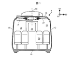
- FIG. 1 shows a cross-sectional configuration in the longitudinal direction of the railway vehicle 1 in the present embodiment.
- a direction related to the railway vehicle 1 is defined.
- the three directions related to the railway vehicle 1 are a vehicle body width direction 80, a vehicle body longitudinal direction 81, and a vehicle body height direction 82 of the railway vehicle 1.
- the width direction 80, the longitudinal direction 81, and the height direction 82 may be simply referred to.
- the railcar 1 includes a base frame 10 that forms a floor, side structures 12 that are erected at both ends in the width direction 80 of the base frame 10, and a side structure 14 that is installed at both ends in the longitudinal direction of the base frame 10. It has a hexahedron box-shaped cabin 20 composed of a roof structure 16 installed at the upper ends of the structure 12 and the wife structure 14.
- the wife structure 14 is provided with a through door 24 for moving to another railway vehicle 1 adjacent in the longitudinal direction 81, and a seat 26, a table (not shown) and the like are installed in the cabin 20.
- an air conditioner 70 that generates conditioned air and adjusts the temperature and humidity environment inside the railway vehicle 1 is installed.
- a ceiling module A having a duct, a ceiling panel and the like for blowing conditioned air to each part of the vehicle body of the railway vehicle 1 is installed.
- the ceiling module A has a plane-symmetric configuration with respect to the central cross section including the center line 90 in the width direction 80.
- FIG. 2 one ceiling module A (FIG. 2) and the lighting device module B (FIG. 3) included in the ceiling module A will be described.
- FIG. 2 shows an enlarged cross-sectional configuration of the ceiling module A.
- the ceiling module A is a member installed on the vehicle interior side of the roof structure 16, and is installed along the longitudinal direction 81 at the center portion in the width direction 80 and the heat insulating material 32 that suppresses the entry and exit of heat between the outside of the vehicle and the inside of the vehicle.
- the conditioned air duct 34, the exhaust air duct 36 installed along the longitudinal direction 81 at both ends in the width direction 80, the ceiling panel 23, and the lighting device module B including the lighting device are included.
- the roof structure 16 is made of an aluminum alloy hollow extruded member in which two facing face plates are connected by a plurality of ribs.
- the underframe 10 and the side structure 12 are similarly configured.
- FIG. 3 shows an enlarged cross-sectional configuration of the lighting device module B
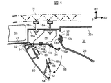
- FIG. 4 shows an enlarged cross-sectional configuration in a state where the lighting device module B is developed
- 5 shows a perspective configuration in a state where the lighting device module B is developed
- FIG. 6 shows a cross-sectional configuration of a casing constituting the lighting device module B.
- the conditioned air generated by the air conditioner 70 is pumped to the conditioned air duct 34 by an indoor blower (not shown).
- the conditioned air duct 34 includes a duct wall 33a disposed substantially horizontally in the vicinity of the roof structure 16, a ceiling panel 23, and a duct wall 33b that connects the duct wall 33a and the ceiling panel 23 and is provided substantially vertically. .
- the duct wall 33a is fixed to the roof structure 16 by a bolt 18a having a head inserted into a slot 16a that is integrally formed with a hollow extruded member constituting the roof structure 16.
- Openings 37 are formed discretely along the longitudinal direction 81 in the duct wall 33b.
- a flow rate adjusting plate 35 that adjusts the flow rate of conditioned air supplied from the conditioned air duct 34 into the cabin 20 by arbitrarily setting the opening ratio is installed in the opening 37.
- the flow rate adjusting plate 35 is fixed to the duct wall 33b with bolts 18d. After the casing 50 is expanded downward in the direction of arrow 98 with the locking portion 56 as a fulcrum, the bolt 18d is loosened to raise the flow rate adjusting plate 35. By adjusting the position in the vertical direction 82, the flow rate of the conditioned air 94 can be arbitrarily adjusted.
- the lighting device module B includes a casing 50 that holds the light emitting unit 52 and a battery 62 that supplies power to the light emitting unit 52 in an emergency, and supports the casing 50 in a deployable manner and conditioned air supplied into the cabin 20 from the opening 37. And a flow dividing plate 39 that branches in the width direction 80.
- the cross-sectional shape intersecting the longitudinal direction 81 of the flow dividing plate 39 is a shape in which one end portion in the width direction 80 is gently inclined downward. Moreover, the cross-sectional shape which cross
- the cross-sectional shape of the lighting device module B provided with the casing 50 below the flow dividing plate 39 has a substantially trapezoidal shape in which the upper side is shorter than the lower side, and the lower side has a convex arc shape downward.
- a placement portion 39a on which a locking portion 56 installed at one end portion of the casing 50 is placed is formed.
- the flow dividing plate 39 constituting the lighting device module B is connected and fixed to one end of the bracket 38 by a bolt 18b.
- the other end of the bracket 38 is connected and fixed to the slot 16a of the roof structure 16 via the bolt 18a.
- the bracket 38 discretely supports the lighting device module B along the longitudinal direction 81, and is installed at a predetermined interval.
- a fastening plate 58 is fixed to the other end of the casing 50.
- the retaining plate 58 is connected to an engaging portion 39b provided at the other end of the flow dividing plate 39 with a bolt 18c.
- the engaging portions 39b are discretely installed at predetermined intervals along the longitudinal direction 81 (FIG. 5).
- the engaging portion 39b may be formed integrally with the flow dividing plate 39 by bending the other end portion of the flow dividing plate 39, or the flow dividing plate 39b prepared as a separate part is attached to the flow dividing plate 39 by spot welding, rivets or the like. It may be fixed.
- the casing 50 can be developed in the direction of the arrow 98 with the locking portion 56 as a fulcrum (FIG. 4).
- a flow path of conditioned air 94 is formed between both ends of the lighting device module B in the width direction 80 and the ceiling panels 23.
- the conditioned air 94 is divided into the conditioned air 94 a that travels from the opening 37 toward the side structure 12 and the conditioned air 94 b that travels toward the center of the cabin 20 in the width direction 80.
- the casing 50 forming the lighting device module B is manufactured by extrusion molding of an aluminum alloy or a nonflammable resin. At both ends of the casing 50 in the width direction 80, accommodating portions 54 in which the light emitting portions 52 are accommodated are formed. The opening part of the accommodating part 54 used for installation or inspection of the light emitting part 52 is closed so that it can be opened and closed by a protective cover 60 having permeability such as polycarbonate resin.
- the light emitting section 52 is a plurality of LED elements arranged at substantially equal intervals on one mounting surface of a substrate extending in a narrow width, and a wiring circuit that electrically connects the LED elements to the other surface of the substrate. And is fixed to the accommodating portion 54 of the casing 50.
- the light trace 96 emitted from the light emitting unit 52 passes through the protective cover 60 and is reflected and diffused by the ceiling panel 23. The reflected light indirectly illuminates the cabin 20.
- the lighting device module B having a substantially trapezoidal cross section is arranged on the flow path downstream of the opening 37 of the conditioned air duct 34. Therefore, the conditioned air 94 supplied into the cabin 20 can be divided into the conditioned air 94a and 94b. Since these conditioned airs 94a and 94b flow along the surface of the ceiling panel 23, it is possible to suppress an unpleasant draft in which passengers are directly exposed to the conditioned air blown out.
- the lower side of the casing 50 having high strength faces the cabin 20 side in a wide range, even if a baggage such as a ski board brought into the cabin 20 by the passenger collides with the lighting device module B, the protective cover 60 and Damage to the light emitting unit 52 can be suppressed.
- the housing unit 54 of the casing 50 holds the fragments or melted material of the protective cover 60. Therefore, it is possible to suppress the protective cover 60 from being scattered or the melt from dripping.
- the accommodating portions 54 are installed at both ends of the substantially trapezoidal width direction 80, the light emitting portion 52 is accommodated in the accommodating portion 54, and the light from the light emitting portion 52 is reflected by the ceiling panel 23. Lighting can be realized.
- the casing 50 is removed from the ceiling module A.
- the flow rate of the conditioned air 94 can be adjusted by the flow rate adjusting plate 35 without being removed. Therefore, the air volume distribution of the railway vehicle 1 can be easily adjusted with less maintenance man-hours.
- the battery 62 can be easily inspected by opening the inspection lid 63 that holds the battery 62 provided in the casing 50 without removing the casing 50.
- the casing 50 is manufactured by extruding an aluminum alloy having high thermal conductivity, the casing 50 is disposed on the flow path of the conditioned air 94, and the housing portion 54 of the casing 50 includes the light emitting portion 52.
- the heat of the light emitting unit 52 can be efficiently removed via the casing 50, and the promotion of deterioration of the light emitting unit 52 can be suppressed. Therefore, the lifetime of the light emitting part 52 can be promoted and the maintenance cost can be suppressed.
Landscapes
- Engineering & Computer Science (AREA)
- Mechanical Engineering (AREA)
- Physics & Mathematics (AREA)
- Thermal Sciences (AREA)
- Life Sciences & Earth Sciences (AREA)
- Wood Science & Technology (AREA)
- Arrangements Of Lighting Devices For Vehicle Interiors, Mounting And Supporting Thereof, Circuits Therefore (AREA)
- Arrangement Of Elements, Cooling, Sealing, Or The Like Of Lighting Devices (AREA)
Abstract
【課題】安全性を維持しつつ、工数を削減するとともに保全性を向上し得る照明装置モジュールを備える軌条車両を提案する。 【解決手段】照明装置モジュールを備える軌条車両において、照明装置モジュールは、調和空気ダクトの吹き出し口近傍に設置され、吹き出し口から吹き出された調和空気を分流する分流板と、分流板の下方に設置されるとともに発光部を収容するケーシングとから構成され、分流板は、幅方向の端部に載置部を備え、ケーシングは、幅方向の端部に係止部を備え、ケーシングの固定を解除すると、係止部を載置部に載置させた状態のまま係止部を支点として下方に展開することを特徴とする。
Description
本発明は、軌条車両に関し、特に照明装置モジュールを備える軌条車両に適用して好適なものである。
軌条車両に供される照明装置は、例えば乗客が車内に持ち込むスキー板等の長尺物が衝突した場合に破片が飛散したり、或いは火災時に溶融した一部が車内に滴下したりしないように安全性を考慮した構成が要求される。
また短時間で点検又は交換することができるように保全性を考慮した構成が望まれる。さらには軌条車両の天井部と側壁との境界部には広告が掲出される場合があり、車内とともにこの広告も照らすことが要求される。
特許文献1には、車内とともに広告も照らす照明装置が開示されている。具体的には、光源から出射された光を下方に向けて反射し、反射した間接光により客室内を照らす反射面を備えるケーシング本体と、光源から出射された光のうち、下方に向かう直接光を遮るための受け部とから構成される照明装置が開示されている。
この特許文献1に記載の照明装置によれば、光源から出射された光のうち、ケーシング本体の下端縁と受け部の上端縁との間から側方に向かう直接光が、天井部と側壁との境界部に掲出された広告を照らすことができるとしている。
ところで軌条車両を少ない工数で製造するためには、従来は別々に取り付けていた部品を一つのまとまった部品に集約して取り付け工数を低減したり、或いは従来は機能ごとに分散して配置されていた部品の機能を一の部品に集約して部品点数を削減したりする等の対策が講じられる。
また軌条車両の天井部には、天井パネル、調和空気の吹き出し口及び照明装置等が設置される。鉄道車両の客室は、幅方向(枕木方向)及び高さ方向の寸法に比較して長手方向(レール方向)に大きな寸法を有しているため、客室内にバランスのよい温度分布を提供するためには調和空気の吹き出し方向や調和空気の流量を微調整する必要がある。
特許文献1に記載の照明装置は、照明装置単体の構成について開示されているだけであり、天井部に設置される部品及び機能を集約して部品点数を削減したり、少ない工数で取り付け又は点検したり、調和空気の流量を調整したりする点で課題がある。
本発明は以上の点を考慮してなされたもので、安全性を維持しつつ、工数を削減するとともに保全性を向上し得る照明装置モジュールを備える軌条車両を提案する。
かかる課題を解決するために、本発明においては、照明装置モジュールを備える軌条車両において、照明装置モジュールは、調和空気ダクトの吹き出し口近傍に設置され、吹き出し口から吹き出された調和空気を分流する分流板と、分流板の下方に設置されるとともに発光部を収容するケーシングとから構成され、分流板は、幅方向の端部に載置部を備え、ケーシングは、幅方向の端部に係止部を備え、ケーシングの固定を解除すると、係止部を載置部に載置させた状態のまま係止部を支点として下方に展開することを特徴とする。
本発明によれば、安全性を維持しつつ、工数を削減するとともに保全性を向上することができる。
以下図面について、本発明の一実施の形態を詳述する。なお軌条車両とは、敷設された軌条に沿って運行する交通車両の総称であり、鉄道車両、路面電車、新交通システム車両及びモノレール車両等が含まれる。以下鉄道車両を例に挙げて説明する。
(1)鉄道車両の構成
図1は、本実施の形態における鉄道車両1の長手方向の断面構成を示す。まず鉄道車両1に関係する方向を定義する。鉄道車両1に関係する3方向は、鉄道車両1の車体幅方向80、車体長手方向81及び車体高さ方向82である。以下では、単に幅方向80、長手方向81及び高さ方向82と称する場合がある。
図1は、本実施の形態における鉄道車両1の長手方向の断面構成を示す。まず鉄道車両1に関係する方向を定義する。鉄道車両1に関係する3方向は、鉄道車両1の車体幅方向80、車体長手方向81及び車体高さ方向82である。以下では、単に幅方向80、長手方向81及び高さ方向82と称する場合がある。
鉄道車両1は、床面をなす台枠10、台枠10の幅方向80の両端部に立設される側構体12、台枠10の長手方向の両端部に設置される妻構体14、側構体12及び妻構体14の上端部に設置される屋根構体16から構成される6面体の箱状の客室20を有する。
妻構体14には、長手方向81に隣接する他の鉄道車両1に移動するための貫通扉24が設置され、また客室20内には、座席26やテーブル(図示省略)等が設置される。
屋根構体16の車外側には、調和空気を生成して鉄道車両1の内部の温湿度環境を整える空調装置70が設置される。屋根構体16の車内側には、調和空気を鉄道車両1の車体の各部に送風するダクトや天井パネル等を有する天井モジュールAが設置される。
天井モジュールAは、幅方向80の中心線90を含む中心断面に対して面対称の構成である。以下では一方の天井モジュールA(図2)及び天井モジュールAに含まれる照明装置モジュールB(図3)について説明する。
(2)天井モジュールの構成
図2は、天井モジュールAの拡大断面構成を示す。天井モジュールAは、屋根構体16の車内側に設置される部材であり、車外と車内との熱の出入りを抑制する断熱材32、幅方向80の中央部に長手方向81に沿って設置される調和空気ダクト34、幅方向80の両端部に長手方向81に沿って設置される排気空気ダクト36、天井パネル23及び照明装置を備える照明装置モジュールB等を含む。
図2は、天井モジュールAの拡大断面構成を示す。天井モジュールAは、屋根構体16の車内側に設置される部材であり、車外と車内との熱の出入りを抑制する断熱材32、幅方向80の中央部に長手方向81に沿って設置される調和空気ダクト34、幅方向80の両端部に長手方向81に沿って設置される排気空気ダクト36、天井パネル23及び照明装置を備える照明装置モジュールB等を含む。
なお屋根構体16は、対向する2枚の面板を複数のリブで接続したアルミ合金製の中空押出形材から構成される。台枠10や側構体12も同様に構成される。
(3)照明装置モジュールの構成
図3は、照明装置モジュールBの拡大断面構成を示し、図4は、照明装置モジュールBを展開した状態の拡大断面構成を示す。また図5は、照明装置モジュールBを展開した状態の斜視構成を示し、図6は、照明装置モジュールBを構成するケーシングの断面構成を示す。以下図3~図6を参照して、照明装置モジュールBの構成について説明する。
図3は、照明装置モジュールBの拡大断面構成を示し、図4は、照明装置モジュールBを展開した状態の拡大断面構成を示す。また図5は、照明装置モジュールBを展開した状態の斜視構成を示し、図6は、照明装置モジュールBを構成するケーシングの断面構成を示す。以下図3~図6を参照して、照明装置モジュールBの構成について説明する。
空調装置70により生成された調和空気は、室内送風機(図示省略)により調和空気ダクト34に圧送される。調和空気ダクト34は、屋根構体16の近傍にほぼ水平に配置されるダクト壁33a、天井パネル23及びダクト壁33aと天井パネル23とを接続するとともにほぼ垂直に備えられるダクト壁33bから構成される。
ダクト壁33aは、屋根構体16を構成する中空押出形材と一体に押出成形されたスロット16aに頭部が挿入されたボルト18aによって、屋根構体16に固定されている。
ダクト壁33bには、長手方向81に沿って離散的に開口部37が形成される。開口部37には、その開口率を任意に設定して調和空気ダクト34から客室20内に供給される調和空気の流量を調整する流量調整板35が設置される。
流量調整板35は、ダクト壁33bにボルト18dで固定されており、ケーシング50を矢印98の方向に係止部56を支点に下方へ展開した後、ボルト18dを緩めて流量調整板35を高さ方向82に位置調整することで調和空気94の流量を任意に調整することができる。
照明装置モジュールBは、発光部52や非常時に発光部52に給電する電池62を保持するケーシング50と、ケーシング50を展開可能に支持するとともに開口部37から客室20内に供給される調和空気を幅方向80に分流する分流板39とから構成される。
分流板39の長手方向81に交差する断面形状は、幅方向80の一方の端部が緩やかに下方に傾斜する形状である。またケーシング50の長手方向81に交差する断面形状は、下面の幅方向の両端部が上方に持ち上げられる円弧形状である。
分流板39の下方にケーシング50を備えた照明装置モジュールBの断面形状は、全体として、上辺が下辺より短い略台形状であり、下辺が下方に向けて凸の円弧形状を有する。
分流板39の幅方向80の一方の端部には、ケーシング50の一方の端部に設置される係止部56が載置される載置部39aが形成される。照明装置モジュールBを構成する分流板39は、ボルト18bによりブラケット38の一端に接続して固定される。
ブラケット38の他端は、ボルト18aを介して屋根構体16のスロット16aに接続して固定される。ブラケット38は、照明装置モジュールBを長手方向81に沿って離散的に支持しており、所定の間隔で設置される。
ケーシング50の他方の端部には、留め板58が固定されている。留め板58は、分流板39の他方の端部に設けられる係合部39bにボルト18cで接続される。係合部39bは、長手方向81に沿って所定の間隔で離散的に設置されている(図5)。
係合部39bは、分流板39の他方の端部を曲げ加工によって分流板39と一体に構成してもよいし、別部品で準備した分流板39bをスポット溶接やリベット等で分流板39に固定してもよい。ボルト18cを取り除くと、係止部56を支点にしてケーシング50を矢印98の方向に展開することができる(図4)。
照明装置モジュールBの幅方向80の両端部と各天井パネル23との間には調和空気94の流路が形成される。調和空気94は、開口部37から側構体12に向かう調和空気94aと、客室20の幅方向80の中央部に向かう調和空気94bとに分流される。
照明装置モジュールBを形成するケーシング50は、アルミニウム合金または不燃性の樹脂を押出成形によって製造される。ケーシング50の幅方向80の両端部には、発光部52が納められる収容部54が形成される。発光部52の設置や点検等に供される収容部54の開口部は、例えばポリカーボネード樹脂のような透過性を有す保護カバー60によって開閉可能に閉じられる。
発光部52は、細幅状に延びる基板の一方の実装面上にほぼ等間隔に配列された複数個のLED素子であり、基板の他方の面にはLED素子を電気的に接続する配線回路が形成されるとともにケーシング50の収容部54に固定される。発光部52から照射される光跡96は、保護カバー60を透過し、天井パネル23で反射して拡散する。反射光は、客室20内を間接的に照らす。
(4)本実施の形態による効果
以上のように本実施の形態によれば、断面形状が略台形状の照明装置モジュールBを調和空気ダクト34の開口部37の下流の流路上に配置するようにしたので、客室20内に供給される調和空気94を調和空気94a及び94bに分流することができる。これら調和空気94a及び94bは、天井パネル23の表面に沿うように流れるため、吹き出された調和空気に乗客が直接さらされる不快なドラフトを抑制することができる。
以上のように本実施の形態によれば、断面形状が略台形状の照明装置モジュールBを調和空気ダクト34の開口部37の下流の流路上に配置するようにしたので、客室20内に供給される調和空気94を調和空気94a及び94bに分流することができる。これら調和空気94a及び94bは、天井パネル23の表面に沿うように流れるため、吹き出された調和空気に乗客が直接さらされる不快なドラフトを抑制することができる。
また高い強度を有するケーシング50の下辺が客室20側に広範囲に対向するようにしたので、乗客が客室20に持ち込んだスキー板等の手荷物が照明装置モジュールBに衝突しても、保護カバー60及び発光部52の破損を抑制することができる。
また万が一、保護カバー60が破損した場合又は発光部52が電気的なショート等の熱で溶融した場合であっても、保護カバー60の破片や溶融物をケーシング50の収容部54が保持するようにしたので、保護カバー60が飛散したり溶融物が滴下したりすることを抑制することができる。
また略台形状の幅方向80の両端部に収容部54を設置し、この収容部54に発光部52を収容し、発光部52からの光を天井パネル23で反射させるようにしたので、間接照明を実現することができる。
また分流板39に設けた載置部39aにケーシング50の係止部56を係止し、係止部56を支点としてケーシング50を下方に展開できる構成としたので、天井モジュールAからケーシング50を取り外すことなく、調和空気94の流量を流量調整板35により調整することができる。よって鉄道車両1の風量分布を少ない保守工数で容易に調整することができる。
またケーシング50を取り外すことなく、ケーシング50に備えられる電池62を保持する点検蓋63を開けて電池62を容易に点検することができる。
またケーシング50は、熱伝導率の高いアルミニウム合金を押出成形して製造し、このケーシング50を調和空気94の流路上に配置し、ケーシング50の収容部54に発光部52を備えるようにしたので、発光部52の熱をケーシング50を介して効率的に取り除くことができ、発光部52の劣化の促進を抑制することができる。よって発光部52の長寿命化を促進して保守コストを抑制することできる。
1 鉄道車両
16 屋根構体
20 客室
22 天井部
23 天井パネル
34 調和空気ダクト
35 流量調整板
37 開口部
38 ブラケット
39 分流板
39a 載置部
50 ケーシング
52 発光部
54 収容部
56 係止部
58 留め板
60 保護カバー
62 電池
63 点検蓋
70 空調装置
80 幅方向
81 長手方向
82 高さ方向
94 調和空気の流れ
96 光線の軌跡
A 天井モジュール
B 照明装置モジュール
16 屋根構体
20 客室
22 天井部
23 天井パネル
34 調和空気ダクト
35 流量調整板
37 開口部
38 ブラケット
39 分流板
39a 載置部
50 ケーシング
52 発光部
54 収容部
56 係止部
58 留め板
60 保護カバー
62 電池
63 点検蓋
70 空調装置
80 幅方向
81 長手方向
82 高さ方向
94 調和空気の流れ
96 光線の軌跡
A 天井モジュール
B 照明装置モジュール
Claims (7)
- 照明装置モジュールを備える軌条車両において、
前記照明装置モジュールは、
調和空気ダクトの吹き出し口近傍に設置され、
前記吹き出し口から吹き出される調和空気を分流する分流板と、
前記分流板の下方に設置されるとともに発光部を収容するケーシングとから構成され、
前記分流板は、幅方向の端部に載置部を備え、
前記ケーシングは、幅方向の端部に係止部を備え、前記ケーシングの固定を解除すると、前記係止部を前記載置部に載置させた状態のまま前記係止部を支点として下方に展開する
ことを特徴とする軌条車両。 - 前記調和空気ダクトは、
前記吹き出し口に該吹き出し口の開口率を調整する流量調整板を備える
ことを特徴とする請求項1に記載の軌条車両。 - 前記照明装置モジュールは、
長手方向に交差する断面形状の上辺が下辺よりも短い略台形状であり、前記下辺は下方に向けて凸の円弧形状である
ことを特徴とする請求項2に記載の軌条車両。 - 前記ケーシングは、
幅方向の両端部に前記発光部を収容する収容部と、
前記収容部に収容された発光部を保護する保護部材とを備える
ことを特徴とする請求項3に記載の軌条車両。 - 前記分流板は、
前記調和空気を幅方向の中央部に向かう流れと、端部に向かう流れとに分流する
ことを特徴とする請求項4に記載の軌条車両。 - 前記ケーシングは、アルミニウム合金を押出成形した形材であり、
前記発光部は、基板の一方の面にLED素子が設置され、他方の面に配線が設置され、
前記発光部の熱は、前記ケーシングを介して前記調和空気によって取り除かれる
ことを特徴とする請求項5に記載の軌条車両。 - 前記発光部から照射された光は、前記照明装置モジュールの近傍に設置される天井パネルに反射した後、前記軌条車両の車内を照らす
ことを特徴とする請求項6に記載の軌条車両。
Priority Applications (3)
| Application Number | Priority Date | Filing Date | Title |
|---|---|---|---|
| PCT/JP2014/079586 WO2016072016A1 (ja) | 2014-11-07 | 2014-11-07 | 軌条車両 |
| EP14905293.8A EP3231684B1 (en) | 2014-11-07 | 2014-11-07 | Rail vehicle |
| JP2016557425A JP6429894B2 (ja) | 2014-11-07 | 2014-11-07 | 軌条車両 |
Applications Claiming Priority (1)
| Application Number | Priority Date | Filing Date | Title |
|---|---|---|---|
| PCT/JP2014/079586 WO2016072016A1 (ja) | 2014-11-07 | 2014-11-07 | 軌条車両 |
Publications (1)
| Publication Number | Publication Date |
|---|---|
| WO2016072016A1 true WO2016072016A1 (ja) | 2016-05-12 |
Family
ID=55908768
Family Applications (1)
| Application Number | Title | Priority Date | Filing Date |
|---|---|---|---|
| PCT/JP2014/079586 Ceased WO2016072016A1 (ja) | 2014-11-07 | 2014-11-07 | 軌条車両 |
Country Status (3)
| Country | Link |
|---|---|
| EP (1) | EP3231684B1 (ja) |
| JP (1) | JP6429894B2 (ja) |
| WO (1) | WO2016072016A1 (ja) |
Cited By (6)
| Publication number | Priority date | Publication date | Assignee | Title |
|---|---|---|---|---|
| CN105936281A (zh) * | 2016-06-20 | 2016-09-14 | 中车青岛四方机车车辆股份有限公司 | 一种轨道车辆防脱落灯具 |
| WO2017202685A1 (de) * | 2016-05-25 | 2017-11-30 | Siemens Ag Österreich | Beleuchtungseinrichtung für ein fahrzeug |
| JP2019006243A (ja) * | 2017-06-23 | 2019-01-17 | 東海旅客鉄道株式会社 | 鉄道車両 |
| JP2019093925A (ja) * | 2017-11-24 | 2019-06-20 | 日本車輌製造株式会社 | 鉄道車両 |
| JP2023049519A (ja) * | 2021-09-29 | 2023-04-10 | コイト電工株式会社 | 照明装置 |
| JP2024094486A (ja) * | 2022-12-28 | 2024-07-10 | 日本車輌製造株式会社 | 鉄道車両 |
Families Citing this family (4)
| Publication number | Priority date | Publication date | Assignee | Title |
|---|---|---|---|---|
| JP6550037B2 (ja) * | 2016-12-26 | 2019-07-24 | 川崎重工業株式会社 | 鉄道車両 |
| US10563859B2 (en) | 2018-05-04 | 2020-02-18 | Ford Global Technologies, Llc | Apparatus for providing independently controlled indirect lighting and airstream to an individual passenger of a motor vehicle |
| IT202100010730A1 (it) * | 2021-04-28 | 2022-10-28 | Iveco France Sas | Sistema di illuminazione per un veicolo per trasporto pubblico |
| EP4442530A1 (en) * | 2023-04-07 | 2024-10-09 | ALSTOM Holdings | Modular ceiling for railway vehicles, and railway vehicle comprising such modular ceiling |
Citations (5)
| Publication number | Priority date | Publication date | Assignee | Title |
|---|---|---|---|---|
| JPH11192942A (ja) * | 1998-01-08 | 1999-07-21 | Hitachi Ltd | 鉄道車両用空調装置 |
| JP2006079918A (ja) * | 2004-09-09 | 2006-03-23 | Kinki Sharyo Co Ltd | 鉄道車両用灯具 |
| JP2007137405A (ja) * | 2005-03-17 | 2007-06-07 | Hitachi Ltd | 軌条車両 |
| JP2011162085A (ja) * | 2010-02-10 | 2011-08-25 | Mitsubishi Heavy Ind Ltd | 空調システム及び空調システムを搭載する車両 |
| CN102372008A (zh) * | 2011-08-29 | 2012-03-14 | 南车南京浦镇车辆有限公司 | 铁路特种车辆会议室送风道安装方法 |
Family Cites Families (7)
| Publication number | Priority date | Publication date | Assignee | Title |
|---|---|---|---|---|
| US2080960A (en) * | 1936-12-03 | 1937-05-18 | New York Central Railroad Co | Dining car illumination and ventilation |
| JPH04334654A (ja) * | 1991-05-10 | 1992-11-20 | Hitachi Ltd | 車両用空調ダクト |
| US5441326A (en) * | 1993-01-22 | 1995-08-15 | Transmatic, Inc. | Combined air conditioning duct, luggage compartment and lighting fixture for mass transit vehicles |
| JP2000213766A (ja) * | 1999-01-21 | 2000-08-02 | Mitsubishi Electric Corp | カセット型空気調和機および躯体蓄熱空調システム |
| US20030173056A1 (en) * | 2002-03-13 | 2003-09-18 | Mccauley Alvin D. | Mass transit vehicle air distribution assembly |
| JP4418411B2 (ja) * | 2005-07-13 | 2010-02-17 | 近畿車輌株式会社 | 照明器具 |
| CN103998318B (zh) * | 2011-12-27 | 2016-09-21 | 川崎重工业株式会社 | 空调系统及具备该空调系统的铁道列车 |
-
2014
- 2014-11-07 EP EP14905293.8A patent/EP3231684B1/en active Active
- 2014-11-07 WO PCT/JP2014/079586 patent/WO2016072016A1/ja not_active Ceased
- 2014-11-07 JP JP2016557425A patent/JP6429894B2/ja active Active
Patent Citations (5)
| Publication number | Priority date | Publication date | Assignee | Title |
|---|---|---|---|---|
| JPH11192942A (ja) * | 1998-01-08 | 1999-07-21 | Hitachi Ltd | 鉄道車両用空調装置 |
| JP2006079918A (ja) * | 2004-09-09 | 2006-03-23 | Kinki Sharyo Co Ltd | 鉄道車両用灯具 |
| JP2007137405A (ja) * | 2005-03-17 | 2007-06-07 | Hitachi Ltd | 軌条車両 |
| JP2011162085A (ja) * | 2010-02-10 | 2011-08-25 | Mitsubishi Heavy Ind Ltd | 空調システム及び空調システムを搭載する車両 |
| CN102372008A (zh) * | 2011-08-29 | 2012-03-14 | 南车南京浦镇车辆有限公司 | 铁路特种车辆会议室送风道安装方法 |
Non-Patent Citations (1)
| Title |
|---|
| See also references of EP3231684A4 * |
Cited By (8)
| Publication number | Priority date | Publication date | Assignee | Title |
|---|---|---|---|---|
| WO2017202685A1 (de) * | 2016-05-25 | 2017-11-30 | Siemens Ag Österreich | Beleuchtungseinrichtung für ein fahrzeug |
| CN105936281A (zh) * | 2016-06-20 | 2016-09-14 | 中车青岛四方机车车辆股份有限公司 | 一种轨道车辆防脱落灯具 |
| JP2019006243A (ja) * | 2017-06-23 | 2019-01-17 | 東海旅客鉄道株式会社 | 鉄道車両 |
| JP2019093925A (ja) * | 2017-11-24 | 2019-06-20 | 日本車輌製造株式会社 | 鉄道車両 |
| JP2023049519A (ja) * | 2021-09-29 | 2023-04-10 | コイト電工株式会社 | 照明装置 |
| JP7712837B2 (ja) | 2021-09-29 | 2025-07-24 | コイト電工株式会社 | 照明装置 |
| JP2024094486A (ja) * | 2022-12-28 | 2024-07-10 | 日本車輌製造株式会社 | 鉄道車両 |
| JP7553540B2 (ja) | 2022-12-28 | 2024-09-18 | 日本車輌製造株式会社 | 鉄道車両 |
Also Published As
| Publication number | Publication date |
|---|---|
| JP6429894B2 (ja) | 2018-11-28 |
| EP3231684A1 (en) | 2017-10-18 |
| EP3231684B1 (en) | 2020-12-30 |
| JPWO2016072016A1 (ja) | 2017-08-03 |
| EP3231684A4 (en) | 2018-08-08 |
Similar Documents
| Publication | Publication Date | Title |
|---|---|---|
| JP6429894B2 (ja) | 軌条車両 | |
| JP6239162B2 (ja) | 鉄道車両用の一体型シーリングアッセンブリ | |
| KR100737489B1 (ko) | 레일차량 | |
| US6082879A (en) | Combination light fixture/HVAC duct/advertising card holder for mass transit vehicles | |
| JP5921649B2 (ja) | 照明装置 | |
| EP2957476A1 (en) | Vehicle air-conditioning duct, and railway vehicle | |
| JP5865797B2 (ja) | Led照明装置 | |
| JP5600657B2 (ja) | 照明装置 | |
| EP3265417A1 (en) | Elevator car | |
| JP4350851B2 (ja) | 鉄道車両用天井構造及びそれに用いられる形材 | |
| RS63577B1 (sr) | Sklop plafona za vozilo i vozilo sa sklopom plafona | |
| EP1031445A1 (de) | Fahrzeug mit Klimakanal und Beleuchtungseinrichtung | |
| RU2005136950A (ru) | Система освещения отраженным светом, используемая в качестве вентиляционного канала для кабины лифта | |
| CA2796896A1 (en) | Use of aircraft cabin surfaces to guide airflow and sound | |
| JPH07186948A (ja) | 車両用空調ダクト構造 | |
| JP7625402B2 (ja) | 鉄道車両の空気浄化装置 | |
| CN105923000A (zh) | 一种轨道车辆照明灯具 | |
| CN104554309A (zh) | 轨道车辆中顶送风结构及轨道车辆 | |
| JP6896244B2 (ja) | 吹出口装置 | |
| JP2014049263A (ja) | 照明装置 | |
| CN206067757U (zh) | 一种轨道车辆集成灯具 | |
| CN105936281B (zh) | 一种轨道车辆防脱落灯具 | |
| JP6469853B2 (ja) | 天井モジュールを備える軌条車両 | |
| JP7452732B1 (ja) | エレベータの天井ユニット、該エレベータの天井ユニットを備えたエレベータ及び該エレベータの天井ユニットを用いたエレベータ天井の改修方法 | |
| US20240300553A1 (en) | Rail vehicle |
Legal Events
| Date | Code | Title | Description |
|---|---|---|---|
| 121 | Ep: the epo has been informed by wipo that ep was designated in this application |
Ref document number: 14905293 Country of ref document: EP Kind code of ref document: A1 |
|
| ENP | Entry into the national phase |
Ref document number: 2016557425 Country of ref document: JP Kind code of ref document: A |
|
| REEP | Request for entry into the european phase |
Ref document number: 2014905293 Country of ref document: EP |
|
| NENP | Non-entry into the national phase |
Ref country code: DE |