WO2016072033A1 - 放電加工用電極線及びその製造方法 - Google Patents
放電加工用電極線及びその製造方法 Download PDFInfo
- Publication number
- WO2016072033A1 WO2016072033A1 PCT/JP2014/079650 JP2014079650W WO2016072033A1 WO 2016072033 A1 WO2016072033 A1 WO 2016072033A1 JP 2014079650 W JP2014079650 W JP 2014079650W WO 2016072033 A1 WO2016072033 A1 WO 2016072033A1
- Authority
- WO
- WIPO (PCT)
- Prior art keywords
- discharge machining
- phase
- electrode wire
- electric discharge
- copper
- Prior art date
- Legal status (The legal status is an assumption and is not a legal conclusion. Google has not performed a legal analysis and makes no representation as to the accuracy of the status listed.)
- Ceased
Links
Images




Classifications
-
- B—PERFORMING OPERATIONS; TRANSPORTING
- B23—MACHINE TOOLS; METAL-WORKING NOT OTHERWISE PROVIDED FOR
- B23H—WORKING OF METAL BY THE ACTION OF A HIGH CONCENTRATION OF ELECTRIC CURRENT ON A WORKPIECE USING AN ELECTRODE WHICH TAKES THE PLACE OF A TOOL; SUCH WORKING COMBINED WITH OTHER FORMS OF WORKING OF METAL
- B23H7/00—Processes or apparatus applicable to both electrical discharge machining and electrochemical machining
- B23H7/02—Wire-cutting
- B23H7/08—Wire electrodes
-
- H—ELECTRICITY
- H01—ELECTRIC ELEMENTS
- H01B—CABLES; CONDUCTORS; INSULATORS; SELECTION OF MATERIALS FOR THEIR CONDUCTIVE, INSULATING OR DIELECTRIC PROPERTIES
- H01B7/00—Insulated conductors or cables characterised by their form
- H01B7/0009—Details relating to the conductive cores
-
- C—CHEMISTRY; METALLURGY
- C22—METALLURGY; FERROUS OR NON-FERROUS ALLOYS; TREATMENT OF ALLOYS OR NON-FERROUS METALS
- C22F—CHANGING THE PHYSICAL STRUCTURE OF NON-FERROUS METALS AND NON-FERROUS ALLOYS
- C22F1/00—Changing the physical structure of non-ferrous metals or alloys by heat treatment or by hot or cold working
- C22F1/08—Changing the physical structure of non-ferrous metals or alloys by heat treatment or by hot or cold working of copper or alloys based thereon
-
- C—CHEMISTRY; METALLURGY
- C25—ELECTROLYTIC OR ELECTROPHORETIC PROCESSES; APPARATUS THEREFOR
- C25D—PROCESSES FOR THE ELECTROLYTIC OR ELECTROPHORETIC PRODUCTION OF COATINGS; ELECTROFORMING; APPARATUS THEREFOR
- C25D3/00—Electroplating: Baths therefor
- C25D3/02—Electroplating: Baths therefor from solutions
- C25D3/22—Electroplating: Baths therefor from solutions of zinc
-
- C—CHEMISTRY; METALLURGY
- C25—ELECTROLYTIC OR ELECTROPHORETIC PROCESSES; APPARATUS THEREFOR
- C25D—PROCESSES FOR THE ELECTROLYTIC OR ELECTROPHORETIC PRODUCTION OF COATINGS; ELECTROFORMING; APPARATUS THEREFOR
- C25D5/00—Electroplating characterised by the process; Pretreatment or after-treatment of workpieces
- C25D5/48—After-treatment of electroplated surfaces
- C25D5/50—After-treatment of electroplated surfaces by heat-treatment
-
- C—CHEMISTRY; METALLURGY
- C25—ELECTROLYTIC OR ELECTROPHORETIC PROCESSES; APPARATUS THEREFOR
- C25D—PROCESSES FOR THE ELECTROLYTIC OR ELECTROPHORETIC PRODUCTION OF COATINGS; ELECTROFORMING; APPARATUS THEREFOR
- C25D7/00—Electroplating characterised by the article coated
- C25D7/06—Wires; Strips; Foils
- C25D7/0607—Wires
-
- H—ELECTRICITY
- H01—ELECTRIC ELEMENTS
- H01B—CABLES; CONDUCTORS; INSULATORS; SELECTION OF MATERIALS FOR THEIR CONDUCTIVE, INSULATING OR DIELECTRIC PROPERTIES
- H01B1/00—Conductors or conductive bodies characterised by the conductive materials; Selection of materials as conductors
- H01B1/02—Conductors or conductive bodies characterised by the conductive materials; Selection of materials as conductors mainly consisting of metals or alloys
-
- H—ELECTRICITY
- H01—ELECTRIC ELEMENTS
- H01B—CABLES; CONDUCTORS; INSULATORS; SELECTION OF MATERIALS FOR THEIR CONDUCTIVE, INSULATING OR DIELECTRIC PROPERTIES
- H01B13/00—Apparatus or processes specially adapted for manufacturing conductors or cables
- H01B13/0026—Apparatus for manufacturing conducting or semi-conducting layers, e.g. deposition of metal
-
- H—ELECTRICITY
- H01—ELECTRIC ELEMENTS
- H01B—CABLES; CONDUCTORS; INSULATORS; SELECTION OF MATERIALS FOR THEIR CONDUCTIVE, INSULATING OR DIELECTRIC PROPERTIES
- H01B13/00—Apparatus or processes specially adapted for manufacturing conductors or cables
- H01B13/0036—Details
-
- H—ELECTRICITY
- H01—ELECTRIC ELEMENTS
- H01B—CABLES; CONDUCTORS; INSULATORS; SELECTION OF MATERIALS FOR THEIR CONDUCTIVE, INSULATING OR DIELECTRIC PROPERTIES
- H01B7/00—Insulated conductors or cables characterised by their form
- H01B7/17—Protection against damage caused by external factors, e.g. sheaths or armouring
Definitions
- the present invention relates to an electrode wire for electric discharge machining and a manufacturing method thereof.
- An electrode wire for electric discharge machining having a zinc coating on the outer periphery of a core material made of copper or a copper alloy (see, for example, Patent Documents 1 to 3), compared with an electrode wire for electric discharge machining made of only a core material made of copper or a copper alloy, There is an advantage that the surface accuracy of the processed portion of the workpiece is good.
- JP 2002-126950 A Japanese Patent No. 3549663 US Patent No. 8,067,689
- the conventional electrode wire for electric discharge machining having zinc coating when the wire is wound around a bobbin or the like and heat-treated in the form of a coil, the curl is strongly attached, so that the automatic wiring property at the time of electric discharge machining is reduced.
- the electrode wire for electric discharge machining having the above zinc coating is disconnected due to some influence during electric discharge machining, the electrode wire for electric discharge machining is automatically and quickly (at a high speed) to the processed part of the workpiece being processed. ) Difficult to insert.
- the workpiece is thick, etc., if the distance for automatically inserting the electrode wire for electric discharge machining becomes longer, it becomes more difficult to automatically connect the electrode wire for electric discharge machining.
- an object of the present invention is to provide an electrode wire for electric discharge machining that is excellent in automatic connection property at the time of electric discharge machining in an electrode wire for electric discharge machining having a zinc coating on the outer periphery of a core material, and a manufacturing method thereof.
- the present invention provides the following electrode wire for electric discharge machining and a manufacturing method thereof.
- the outer periphery of a core material made of copper or a copper alloy is covered with a coating layer containing zinc, and the coating layer is an inner layer containing a ⁇ phase of a copper-zinc alloy covering the outer periphery on the core material And an outer layer containing an ⁇ phase of a copper-zinc alloy covering the outer periphery of the inner layer, and the (0001) X-ray diffraction intensity of the ⁇ phase is equal to the (332) X-ray diffraction intensity of the ⁇ phase.
- Electrode wire for electric discharge machining larger than twice.
- the outer periphery of the core material is subjected to zinc plating or zinc alloy plating once.
- a step of drawing the plated core material, an inner layer in which the coating layer includes a ⁇ phase of a copper-zinc alloy after the drawing, and a copper-zinc alloy that covers the outer periphery of the inner layer A heat treatment under a heat treatment condition in which the (0001) X-ray diffraction intensity of the ⁇ phase is larger than twice the (332) X-ray diffraction intensity of the ⁇ phase;
- the manufacturing method of the electrode wire for electrical discharge machining containing this.
- an electrode wire for electric discharge machining that is excellent in automatic connection property at the time of electric discharge machining in an electrode wire for electric discharge machining having a zinc coating on the outer periphery of a core material, and a method for manufacturing the same.
- the measurement result of X-ray diffraction intensity is shown, and is the measurement result of the (0001) intensity of the ⁇ phase (CuZn 5 ) at each annealing temperature.
- the measurement result of X-ray diffraction intensity is shown, and is the measurement result of (332) intensity of the ⁇ phase (Cu 5 Zn 8 ) at each annealing temperature.
- the measurement result of X-ray diffraction intensity is shown, and is the measurement result of (100) intensity of ⁇ phase (Zn) at each annealing temperature.
- FIG. 1 is a cross-sectional view showing the structure of an electrode wire for electric discharge machining according to an embodiment of the present invention.
- an electrode wire 10 for electric discharge machining according to an embodiment of the present invention has an outer periphery of a core material 1 made of copper or a copper alloy covered with a coating layer 2 containing zinc.
- 2 has an inner layer 2A containing a ⁇ phase of a copper-zinc alloy covering the outer periphery of the core material 1 and an outer layer 2B containing an ⁇ phase of a copper-zinc alloy covering the outer periphery of the inner layer 2A.
- the (0001) X-ray diffraction intensity of the ⁇ phase is greater than twice the (332) X-ray diffraction intensity of the ⁇ phase.
- Core material 1 is made of copper or a copper alloy. Although it does not specifically limit as a copper alloy, It is preferable that it is a brass.
- the coating layer 2 containing zinc provided on the outer periphery of the core material 1 is provided by applying zinc plating or zinc alloy plating, preferably zinc plating.
- the covering layer 2 has an inner layer 2A containing a copper-zinc alloy ⁇ phase covering the outer periphery of the core material 1, and an outer layer 2B containing a copper-zinc alloy ⁇ phase covering the outer periphery of the inner layer 2A.
- the ⁇ phase is generally a Cu—Zn alloy represented by Cu 5 Zn 8 and having a Cu concentration of about 45 to 35 mass% and a Zn concentration of about 55 to 65 mass%.
- the ⁇ phase is generally a Cu—Zn alloy represented by CuZn 5 and having a Cu concentration of about 24 to 12% by mass and a Zn concentration of about 76 to 88% by mass.
- the outer layer 2B including the ⁇ phase is preferably the outermost layer.
- the inner layer 2A containing the ⁇ phase preferably contains 85% by mass or more of the ⁇ phase in the inner layer, more preferably 90% by mass or more, further preferably 95% by mass or more, and more preferably 100% by mass. Is most preferred.
- the outer layer 2B containing the ⁇ phase preferably contains 85 mass% or more of the ⁇ phase in the outer layer, more preferably 90 mass% or more, further preferably 95 mass% or more, and more preferably 100 mass%. Is most preferred.
- the (0001) X-ray diffraction intensity of the ⁇ phase in the outer layer 2B is greater than twice the (332) X-ray diffraction intensity of the ⁇ phase in the inner layer 2A.
- the (0001) X-ray diffraction intensity of the ⁇ phase is preferably 3 times or more, more preferably 4 times or more of the (332) X-ray diffraction intensity of the ⁇ phase. Although an upper limit is not specifically limited, It is preferable that it is 20 times or less.
- the (0001) X-ray diffraction intensity of the ⁇ phase is preferably 500 to 1200 cps, and more preferably 600 to 1100 cps.
- the (332) X-ray diffraction intensity of the ⁇ phase is preferably 30 to 550 cps, and more preferably 400 to 500 cps.
- the X-ray diffraction intensity is a peak intensity measured by a thin film method (a technique in which the X-ray penetration depth is reduced by fixing incident X-rays at a low angle (for example, 10 °) to increase the analysis sensitivity of the surface layer). It is a comparison.
- the thickness of the coating layer 2 is preferably 1 to 20 ⁇ m as a whole.
- the amount of warpage with respect to the axis along the vertical direction when the electric discharge machining electrode wire 10 according to the embodiment of the present invention is vertically suspended is preferably 80 mm / m or less. Moreover, it is preferable that the difference between the maximum value and the minimum value of the warpage amount in the longitudinal direction of the electric discharge machining electrode wire 10 is 30 mm / m or less.
- the manufacturing method of an electrode wire for electric discharge machining is the method for manufacturing an electrode wire for electric discharge machining in which the outer periphery of a core material made of copper or a copper alloy is covered with a coating layer containing zinc.
- the step of applying zinc plating or zinc alloy plating once and the step of drawing can be performed by a known method.
- the electrode wire for electric discharge machining can be manufactured through a process of performing heat treatment after wire drawing.
- the heat treatment conditions are preferably adjusted so that the inner layer 2A and the outer layer 2B can be formed within a range of 100 to 120 ° C. and 3 to 24 hours, more preferably 100 to 120 ° C. and 3 to 18 hours.
- the heat treatment temperature and time are appropriately adjusted according to the diameter of the electrode wire and the thickness of the coating layer. For example, when heat treatment is performed at 100 ° C., it is preferably about 6 to 10 hours if the diameter of the electrode wire is ⁇ 0.20, and about 10 to 17 hours if the diameter of the electrode wire is ⁇ 0.25.
- the thickness of the coating layer is less than 1.5 ⁇ m, and 7 to 18 if the thickness of the coating layer is 1.5 ⁇ m or more. About hours are preferred.
- the electric discharge machining electrode wire can be automatically and quickly inserted into a very small hole in the workpiece, so that the machining operation It is easy to switch. (3) Since it can be manufactured in a single plating step, it is excellent in productivity. (4) Even if heat treatment (annealing) is performed in a coiled state, an electrode wire for electric discharge machining with less curling is obtained, so that not only the automatic connection property is improved but also the productivity is excellent.
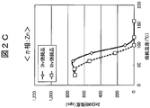
- FIGS. 2A to 2C show the measurement results of the X-ray diffraction intensity
- FIG. 2A shows the measurement results of the (0001) intensity of the ⁇ phase (CuZn 5 ) at each annealing temperature
- FIG. 2B shows the ⁇ at each annealing temperature
- FIG. 2C is a measurement result of (100) strength of ⁇ phase (Zn) at each annealing temperature
- FIG. 2C is a measurement result of (332) strength of phase (Cu 5 Zn 8 ).
- the plots at 25 ° C. in FIGS. 2A to 2C are measurement results of the electric discharge machining electrode wires that were not annealed.
- a zinc plating layer having a thickness of about 10 ⁇ m was formed on the brass wire (wire diameter: 1.2 mm) as the core material 1 by an electrolytic galvanizing method. After drawing the galvanized core material 1 until the wire diameter becomes 0.20 mm (plating layer 1.7 ⁇ m), it is wound around a bobbin (F10: body diameter 100 mm) and annealed in this state. A 10 kg electrode wire for electric discharge machining was produced. The annealing conditions are 40 to 160 ° C. (40, 60, 80, 100, 120, 160 ° C.), 3 hours and 8 hours.
- the (0001) X-ray diffraction intensity of the ⁇ phase is twice the (332) X-ray diffraction intensity of the ⁇ phase at both the annealing time of 3 hours and 8 hours. Can be seen to be large.
- the (100) X-ray diffraction intensity of the ⁇ phase (Zn) becomes 0 at an annealing temperature of 100 ° C.
- the 3-hour annealing product becomes (100) of the ⁇ phase (Zn) at an annealing temperature of 120 ° C.
- the X-ray diffraction intensity was 0 (FIG. 2C).
- the ⁇ phase is a pure Zn phase, and since it is soft, wear powder tends to be produced and accumulates as debris on the pass line of the electric discharge machine. Therefore, it is better to eliminate the ⁇ phase by heat treatment, and it can be seen that heat treatment at 100 ° C. or higher is necessary for that purpose. From the above, heat treatment at 100 ° C. to 120 ° C. is optimal.
- FIG. 3 is a graph showing the straightness evaluation results of the examples and comparative examples.
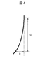
- FIG. 4 is a diagram showing a method for measuring straightness.
- a zinc plating layer having a thickness of about 10 ⁇ m was formed on the brass wire (wire diameter: 1.2 mm) as the core material 1 by an electrolytic galvanizing method. After drawing the galvanized core material 1 until the wire diameter becomes 0.20 mm (plating layer 1.7 ⁇ m), it is wound around a bobbin (F350: trunk diameter 340 mm) and annealed in this state. A 300 kg electric discharge machining electrode wire was produced. The annealing conditions are 100 ° C., 8 hours (Example 1), 160 ° C., 3 hours (Comparative Example 1).
- straightness is the amount of warpage per meter (shown as “D” (width) in FIG. 4) with respect to the axis along the vertical direction when the electric discharge machining electrode wire is suspended vertically. It evaluated by measuring. The amount of warpage was measured approximately every 10 to 15 kg in order from the electrode wire for electric discharge machining outside the bobbin. Since the diameter becomes smaller toward the inside of the bobbin, the amount of warpage becomes larger.
- Example 3 that in Example 1, the amount of warpage was 80 mm / m or less (within a range of 40 to 70 mm / m) over the entire length. The difference between the maximum value and the minimum value of the warp amount was 30 mm / m or less. On the other hand, in Comparative Example 1, the amount of warpage was in the range of 60 to 100 mm / m, and the amount of warpage was 80 mm / m or more from the electrode wire per 75 kg from the outside of the bobbin.
- FIG. 5 is a diagram showing an outline of an apparatus for evaluating the relationship between straightness and automatic connection.
- a zinc plating layer having a thickness of about 10 ⁇ m was formed on a brass wire (wire diameter: 1.2 mm) as the core material 1 by electrolytic galvanization. After drawing the galvanized core material 1 until the wire diameter becomes 0.25 mm (plating layer 2.1 ⁇ m), it is wound around a bobbin (F-350: trunk diameter 340 mm) and annealed in this state. Thereafter, the wire was wound around a bobbin (P-5RT: body diameter 100 mm), and 5 kg of each electrode wire for electric discharge machining was manufactured. The annealing conditions were set at 100 ° C. for 8 hours, and an electric discharge machining electrode wire having a straightness (warping amount) of 40 to 80 mm was produced.
- a zinc plating layer having a thickness of about 10 ⁇ m was formed on a brass wire (wire diameter: 1.2 mm) as the core material 1 by electrolytic galvanization. After drawing the galvanized core material 1 until the wire diameter becomes 0.25 mm (plating layer 2.1 ⁇ m), it is wound around a bobbin (F-350: trunk diameter 340 mm) and annealed in this state. Thereafter, the wire was wound around a bobbin (P-5RT: body diameter 100 mm), and 5 kg of each electrode wire for electric discharge machining was manufactured. The annealing conditions were set at 160 ° C. for 3 hours, and an electric discharge machining electrode wire having a straightness (warping amount) of 90 to 110 mm was produced.
- the manufactured electrode wire 10 of the example or comparative example was set in the apparatus as shown in FIG. Specifically, the electrode wire 10 was passed through the upper guide die 22 ⁇ / b> A and the lower guide die 22 ⁇ / b> B, and the workpiece 20 was processed to make a hole 20 a.
- the upper nozzle 21A and the lower nozzle 21B inject a jet water flow that facilitates the automatic insertion of the electrode wire 10 into the hole 20a (covering the electrode wire with a water pressure of about 2 kgf / cm 2 and a water column of ⁇ 2 mm, To help with insertion).
- the distance from the lower end of the upper nozzle 21A to the upper end of the lower nozzle 21B is the Z-axis height H shown in FIG.
- the processing machine used was a product name: FK-K manufactured by Mitsubishi Electric Corporation
- the pilot hole was fixed to ⁇ 3 mm
- the Z-axis height H was set to 50, 100, and 150 mm, respectively. .
- the disconnected electrode wire 10 was recovered as a scrap wire 25 via a roller 23 and a recovery roller 24.
- the number of measurements was defined as 50 consecutive times, and the automatic connection rate of 80% or higher was defined as a practically acceptable level for any of the Z-axis heights of 50, 100, and 150 mm.
- the connection is automatically retried if it fails once, but only when it succeeds once is counted as a success. The results are shown in Table 1.
- the automatic connection rate was 80% or more at any of the Z-axis heights of 50, 100, and 150 mm. That is, with the electrode wire for electric discharge machining according to the present invention, a high automatic connection rate can be maintained even when the distance for automatic insertion becomes long.
- Electrode wire 20 Work piece, 20a: Hole 21A: Upper nozzle, 21B: Lower nozzle 22A: Upper guide die, 22B: Lower guide die 23: Roller, 24: Recovery roller, 25: Scrap wire
Landscapes
- Chemical & Material Sciences (AREA)
- Engineering & Computer Science (AREA)
- Organic Chemistry (AREA)
- Electrochemistry (AREA)
- Chemical Kinetics & Catalysis (AREA)
- Materials Engineering (AREA)
- Metallurgy (AREA)
- Mechanical Engineering (AREA)
- Manufacturing & Machinery (AREA)
- Physics & Mathematics (AREA)
- Crystallography & Structural Chemistry (AREA)
- Thermal Sciences (AREA)
- Electrical Discharge Machining, Electrochemical Machining, And Combined Machining (AREA)
Abstract
Description
[2]前記放電加工用電極線を鉛直に垂らしたときの鉛直方向に沿った軸に対する反り量が80mm/m以下である前記[1]に記載の放電加工用電極線。
[3]前記外層は、最外層である前記[1]又は[2]に記載の放電加工用電極線。
[4]前記芯材は、黄銅からなる前記[1]~[3]のいずれか1つに記載の放電加工用電極線。
[5]銅又は銅合金からなる芯材の外周が亜鉛を含む被覆層により被覆されている放電加工用電極線の製造方法において、前記芯材の外周に亜鉛めっき又は亜鉛合金めっきを1回施す工程と、めっきを施した前記芯材を伸線する工程と、伸線後に、前記被覆層が銅-亜鉛系合金のγ相を含む内層と、前記内層の外周を被覆する銅-亜鉛系合金のε相を含む外層とを有し、前記ε相の(0001)X線回折強度が、前記γ相の(332)X線回折強度の2倍よりも大きくなる熱処理条件で熱処理を施す工程とを含む放電加工用電極線の製造方法。
図1は、本発明の実施の形態に係る放電加工用電極線の構造を示す横断面図である。
本発明の実施の形態に係る放電加工用電極線10は、図1に示されるように、銅又は銅合金からなる芯材1の外周が亜鉛を含む被覆層2により被覆されており、被覆層2は、芯材1上の外周を被覆する銅-亜鉛系合金のγ相を含む内層2Aと、内層2Aの外周を被覆する銅-亜鉛系合金のε相を含む外層2Bとを有し、ε相の(0001)X線回折強度が、γ相の(332)X線回折強度の2倍よりも大きいことを特徴とする。
本発明の実施の形態に係る放電加工用電極線の製造方法は、銅又は銅合金からなる芯材の外周が亜鉛を含む被覆層により被覆されている放電加工用電極線の製造方法において、前記芯材の外周に亜鉛めっき又は亜鉛合金めっきを1回施す工程と、めっきを施した前記芯材を伸線する工程と、伸線後に、前記被覆層が銅-亜鉛系合金のγ相を含む内層と、前記内層の外周を被覆する銅-亜鉛系合金のε相を含む外層とを有し、前記ε相の(0001)X線回折強度が、前記γ相の(332)X線回折強度の2倍よりも大きくなる熱処理条件で熱処理を施す工程とを含むことを特徴とする。
本発明の実施形態によれば、以下の効果を奏する。
(1)芯材の外周に亜鉛被覆を有する放電加工用電極線において真直性が改善されたことにより放電加工の際の自動結線性に優れる放電加工用電極線及びその製造方法を提供できる。例えば、黄銅線のみからなる放電加工用電極線に匹敵する自動結線のし易さを持つ放電加工用電極線を得ることができる。また、亜鉛濃度の高いε相を含む外層2Bを最外層に設けることにより、放電加工特性が更に優れる放電加工用電極線を得ることができる。
(2)被加工物の他の加工部位へ加工作業を切り替える段取り工程において、被加工物のごく僅かな大きさの孔へ自動で素早く放電加工用電極線を挿通させることができるため、加工作業の切り替えが行いやすい。
(3)1回のめっき工程で製造できるため生産性に優れる。
(4)コイル状に巻いた状態で熱処理(焼鈍)しても巻き癖の少ない放電加工用電極線が得られるため、自動結線性が改善されるのみならず、生産性にも優れる。
下記の方法により放電加工用電極線を製造し、X線回折強度の測定を行なった。図2A~Cは、X線回折強度の測定結果を示しており、図2Aは各焼鈍温度におけるε相(CuZn5)の(0001)強度の測定結果であり、図2Bは各焼鈍温度におけるγ相(Cu5Zn8)の(332)強度の測定結果であり、図2Cは各焼鈍温度におけるη相(Zn)の(100)強度の測定結果である。なお、図2A~Cにおける25℃のプロットは、焼鈍しなかった放電加工用電極線の測定結果である。
上記より100℃~120℃の熱処理が最適である。
下記の方法により放電加工用電極線を製造し、真直性の評価を行なった。図3は、実施例及び比較例の真直性の評価結果を示すグラフである。また、図4は、真直性の測定方法を示す図である。
下記の方法により放電加工用電極線を製造し、真直性(反り量=幅)が自動結線率に及ぼす影響について評価を行なった。図5は、真直性と自動結線性の関係性の評価を行うための装置の概略を示す図である。
芯材1としての黄銅線(線径:1.2mm)上に電解亜鉛めっき法により厚さ約10μmの亜鉛めっき層を形成した。亜鉛めっきを施した芯材1を線径が0.25mm(めっき層2.1μm)になるまで伸線した後、ボビン(F-350:胴径340mm)に巻き取り、この状態で焼鈍を行ない、その後、ボビン(P-5RT:胴径100mm)に巻き替え、各5kgの放電加工用電極線を製造した。焼鈍条件は、100℃、8時間で設定し、真直性(反り量)が40~80mmの放電加工用電極線を製造した。
芯材1としての黄銅線(線径:1.2mm)上に電解亜鉛めっき法により厚さ約10μmの亜鉛めっき層を形成した。亜鉛めっきを施した芯材1を線径が0.25mm(めっき層2.1μm)になるまで伸線した後、ボビン(F-350:胴径340mm)に巻き取り、この状態で焼鈍を行ない、その後、ボビン(P-5RT:胴径100mm)に巻き替え、各5kgの放電加工用電極線を製造した。焼鈍条件は、160℃、3時間で設定し、真直性(反り量)が90~110mmの放電加工用電極線を製造した。

10:電極線
20:加工物、20a:孔
21A:上部ノズル、21B:下部ノズル
22A:上部ガイドダイス、22B:下部ガイドダイス
23:ローラー、24:回収ローラー、25:スクラップワイヤ
Claims (5)
- 銅又は銅合金からなる芯材の外周が亜鉛を含む被覆層により被覆されており、
前記被覆層は、前記芯材上の外周を被覆する銅-亜鉛系合金のγ相を含む内層と、前記内層の外周を被覆する銅-亜鉛系合金のε相を含む外層とを有し、
前記ε相の(0001)X線回折強度が、前記γ相の(332)X線回折強度の2倍よりも大きい放電加工用電極線。 - 前記放電加工用電極線を鉛直に垂らしたときの鉛直方向に沿った軸に対する反り量が80mm/m以下である請求項1に記載の放電加工用電極線。
- 前記外層は、最外層である請求項1又は請求項2に記載の放電加工用電極線。
- 前記芯材は、黄銅からなる請求項1~3のいずれか1項に記載の放電加工用電極線。
- 銅又は銅合金からなる芯材の外周が亜鉛を含む被覆層により被覆されている放電加工用電極線の製造方法において、
前記芯材の外周に亜鉛めっき又は亜鉛合金めっきを1回施す工程と、
めっきを施した前記芯材を伸線する工程と、
伸線後に、前記被覆層が銅-亜鉛系合金のγ相を含む内層と、前記内層の外周を被覆する銅-亜鉛系合金のε相を含む外層とを有し、前記ε相の(0001)X線回折強度が、前記γ相の(332)X線回折強度の2倍よりも大きくなる熱処理条件で熱処理を施す工程とを含む放電加工用電極線の製造方法。
Priority Applications (5)
| Application Number | Priority Date | Filing Date | Title |
|---|---|---|---|
| EP14905649.1A EP3216548B1 (en) | 2014-11-07 | 2014-11-07 | Electrode wire for electrical discharge machining and manufacturing method for same |
| PCT/JP2014/079650 WO2016072033A1 (ja) | 2014-11-07 | 2014-11-07 | 放電加工用電極線及びその製造方法 |
| KR1020167016940A KR101892371B1 (ko) | 2014-11-07 | 2014-11-07 | 방전 가공용 전극선 및 그 제조 방법 |
| JP2016521807A JP6418507B2 (ja) | 2014-11-07 | 2014-11-07 | 放電加工用電極線の製造方法 |
| US15/107,119 US10307848B2 (en) | 2014-11-07 | 2014-11-07 | Electrical discharge machining electrode wire and manufacturing method for same |
Applications Claiming Priority (1)
| Application Number | Priority Date | Filing Date | Title |
|---|---|---|---|
| PCT/JP2014/079650 WO2016072033A1 (ja) | 2014-11-07 | 2014-11-07 | 放電加工用電極線及びその製造方法 |
Publications (1)
| Publication Number | Publication Date |
|---|---|
| WO2016072033A1 true WO2016072033A1 (ja) | 2016-05-12 |
Family
ID=55908784
Family Applications (1)
| Application Number | Title | Priority Date | Filing Date |
|---|---|---|---|
| PCT/JP2014/079650 Ceased WO2016072033A1 (ja) | 2014-11-07 | 2014-11-07 | 放電加工用電極線及びその製造方法 |
Country Status (5)
| Country | Link |
|---|---|
| US (1) | US10307848B2 (ja) |
| EP (1) | EP3216548B1 (ja) |
| JP (1) | JP6418507B2 (ja) |
| KR (1) | KR101892371B1 (ja) |
| WO (1) | WO2016072033A1 (ja) |
Cited By (1)
| Publication number | Priority date | Publication date | Assignee | Title |
|---|---|---|---|---|
| EP3100812A4 (en) * | 2015-01-07 | 2017-10-04 | Hitachi Metals, Ltd. | Electric discharge machining electrode wire and manufacturing method therefor |
Families Citing this family (5)
| Publication number | Priority date | Publication date | Assignee | Title |
|---|---|---|---|---|
| KR20160113285A (ko) | 2015-01-07 | 2016-09-28 | 히타치 긴조쿠 가부시키가이샤 | 방전 가공용 전극선 및 그 제조 방법 |
| CN110093644B (zh) * | 2019-05-15 | 2021-04-16 | 江苏兴达钢帘线股份有限公司 | 一种钢丝、其制造方法、钢丝绳及输送带 |
| CN114211063B (zh) * | 2021-10-18 | 2022-12-20 | 宁波博德高科股份有限公司 | 一种电火花放电加工用电极丝及其制备方法 |
| FR3129098B1 (fr) | 2021-11-16 | 2024-07-26 | Thermocompact Sa | Fil électrode |
| JP7823530B2 (ja) * | 2022-09-09 | 2026-03-04 | 株式会社プロテリアル | ワイヤー放電加工用電極線 |
Citations (2)
| Publication number | Priority date | Publication date | Assignee | Title |
|---|---|---|---|---|
| US5945010A (en) * | 1997-09-02 | 1999-08-31 | Composite Concepts Company, Inc. | Electrode wire for use in electric discharge machining and process for preparing same |
| US20090025959A1 (en) * | 2005-12-01 | 2009-01-29 | Dandridge Tomalin | Edm wire |
Family Cites Families (12)
| Publication number | Priority date | Publication date | Assignee | Title |
|---|---|---|---|---|
| JPS549663A (en) | 1977-06-23 | 1979-01-24 | Seiko Epson Corp | Electronic wristwatch |
| JPS61182729A (ja) * | 1985-02-09 | 1986-08-15 | Fanuc Ltd | ワイヤカツト放電加工機のテ−パ加工制御装置 |
| JP3566988B2 (ja) * | 1994-07-27 | 2004-09-15 | ファナック株式会社 | ワイヤ放電加工方法 |
| US5762726A (en) | 1995-03-24 | 1998-06-09 | Berkenhoff Gmbh | Wire electrode and process for producing a wire electrode, particular for a spark erosion process |
| DE19510740A1 (de) | 1995-03-24 | 1996-10-02 | Berkenhoff Gmbh | Drahtelektrode sowie Verfahren zur Herstellung einer Drahtelektrode, insbesondere für das Funkenerodierverfahren |
| CH690420A5 (fr) * | 1995-05-11 | 2000-09-15 | Charmilles Technologies | Dispositif pour machine d'usinage par électroérosion. |
| JPH10128623A (ja) | 1996-10-30 | 1998-05-19 | Hitachi Cable Ltd | 放電加工用電極線の製造方法及びその装置 |
| JP2002126950A (ja) | 2000-10-23 | 2002-05-08 | Sumitomo Metal Mining Co Ltd | ワイヤ放電加工用電極線の製造方法 |
| KR100528850B1 (ko) * | 2004-02-05 | 2005-11-21 | 주식회사 풍국통상 | 방전가공기용의 다기능 다층 코팅 전극선 및 그의 제조방법 |
| KR20140051734A (ko) * | 2012-10-23 | 2014-05-02 | 성기철 | 방전가공용 전극선 및 그 제조방법 |
| CN104191056B (zh) * | 2014-08-13 | 2016-06-29 | 宁波博威麦特莱科技有限公司 | 一种高精度锌基合金电极丝及其制备方法 |
| KR20160113285A (ko) * | 2015-01-07 | 2016-09-28 | 히타치 긴조쿠 가부시키가이샤 | 방전 가공용 전극선 및 그 제조 방법 |
-
2014
- 2014-11-07 JP JP2016521807A patent/JP6418507B2/ja active Active
- 2014-11-07 KR KR1020167016940A patent/KR101892371B1/ko active Active
- 2014-11-07 EP EP14905649.1A patent/EP3216548B1/en active Active
- 2014-11-07 WO PCT/JP2014/079650 patent/WO2016072033A1/ja not_active Ceased
- 2014-11-07 US US15/107,119 patent/US10307848B2/en active Active
Patent Citations (2)
| Publication number | Priority date | Publication date | Assignee | Title |
|---|---|---|---|---|
| US5945010A (en) * | 1997-09-02 | 1999-08-31 | Composite Concepts Company, Inc. | Electrode wire for use in electric discharge machining and process for preparing same |
| US20090025959A1 (en) * | 2005-12-01 | 2009-01-29 | Dandridge Tomalin | Edm wire |
Non-Patent Citations (1)
| Title |
|---|
| See also references of EP3216548A4 * |
Cited By (2)
| Publication number | Priority date | Publication date | Assignee | Title |
|---|---|---|---|---|
| EP3100812A4 (en) * | 2015-01-07 | 2017-10-04 | Hitachi Metals, Ltd. | Electric discharge machining electrode wire and manufacturing method therefor |
| US10384282B2 (en) | 2015-01-07 | 2019-08-20 | Hitachi Metals, Ltd. | Electric discharge machining electrode wire and manufacturing method therefor |
Also Published As
| Publication number | Publication date |
|---|---|
| KR101892371B1 (ko) | 2018-08-27 |
| JP6418507B2 (ja) | 2018-11-07 |
| EP3216548A1 (en) | 2017-09-13 |
| US20170259361A1 (en) | 2017-09-14 |
| KR20160091376A (ko) | 2016-08-02 |
| JPWO2016072033A1 (ja) | 2017-08-03 |
| EP3216548A4 (en) | 2018-04-25 |
| US10307848B2 (en) | 2019-06-04 |
| EP3216548B1 (en) | 2019-02-27 |
Similar Documents
| Publication | Publication Date | Title |
|---|---|---|
| JP6418507B2 (ja) | 放電加工用電極線の製造方法 | |
| JP6558605B2 (ja) | 放電加工用電極線 | |
| JP6089128B2 (ja) | 放電加工用電極線 | |
| CN104994984B (zh) | 线放电加工用电极线及其制造方法 | |
| EP2551856B1 (en) | High frequency cable and high frequency coil | |
| JP6369546B2 (ja) | 放電加工用電極線及びその製造方法 | |
| JP6317908B2 (ja) | 放電加工用電極線およびその製造方法 | |
| CN110277192B (zh) | 镀锡铜线及其制造方法以及绝缘电线、电缆 | |
| JP6655769B1 (ja) | めっき線棒、当該めっき線棒の製造方法、並びに、当該めっき線棒を用いた、ケーブル、電線、コイル、ワイヤハーネス、ばね部材、エナメル線、及び、リード線 | |
| JP6369545B2 (ja) | 放電加工用電極線及びその製造方法 | |
| CN105283262B (zh) | 用于放电切割物体的电极丝 | |
| JP2014136285A (ja) | 放電加工用ワイヤーおよびその製造方法 | |
| JP2014200872A (ja) | 放電加工用電極線およびその製造方法 | |
| JP2020049573A (ja) | 放電加工用電極線 | |
| JP2005138236A (ja) | 放電加工用電極線の製造方法及び放電加工用電極線 |
Legal Events
| Date | Code | Title | Description |
|---|---|---|---|
| ENP | Entry into the national phase |
Ref document number: 2016521807 Country of ref document: JP Kind code of ref document: A |
|
| 121 | Ep: the epo has been informed by wipo that ep was designated in this application |
Ref document number: 14905649 Country of ref document: EP Kind code of ref document: A1 |
|
| WWE | Wipo information: entry into national phase |
Ref document number: 15107119 Country of ref document: US |
|
| ENP | Entry into the national phase |
Ref document number: 20167016940 Country of ref document: KR Kind code of ref document: A |
|
| REEP | Request for entry into the european phase |
Ref document number: 2014905649 Country of ref document: EP |
|
| WWE | Wipo information: entry into national phase |
Ref document number: 2014905649 Country of ref document: EP |
|
| NENP | Non-entry into the national phase |
Ref country code: DE |