WO2016072416A1 - 核酸導入方法、核酸検出方法、生体成分解析方法、生体成分定量用アレイデバイス、及び生体成分解析キット - Google Patents
核酸導入方法、核酸検出方法、生体成分解析方法、生体成分定量用アレイデバイス、及び生体成分解析キット Download PDFInfo
- Publication number
- WO2016072416A1 WO2016072416A1 PCT/JP2015/081029 JP2015081029W WO2016072416A1 WO 2016072416 A1 WO2016072416 A1 WO 2016072416A1 JP 2015081029 W JP2015081029 W JP 2015081029W WO 2016072416 A1 WO2016072416 A1 WO 2016072416A1
- Authority
- WO
- WIPO (PCT)
- Prior art keywords
- nucleic acid
- biological component
- array device
- modification
- wells
- Prior art date
- Legal status (The legal status is an assumption and is not a legal conclusion. Google has not performed a legal analysis and makes no representation as to the accuracy of the status listed.)
- Ceased
Links
Images











Classifications
-
- C—CHEMISTRY; METALLURGY
- C12—BIOCHEMISTRY; BEER; SPIRITS; WINE; VINEGAR; MICROBIOLOGY; ENZYMOLOGY; MUTATION OR GENETIC ENGINEERING
- C12M—APPARATUS FOR ENZYMOLOGY OR MICROBIOLOGY; APPARATUS FOR CULTURING MICROORGANISMS FOR PRODUCING BIOMASS, FOR GROWING CELLS OR FOR OBTAINING FERMENTATION OR METABOLIC PRODUCTS, i.e. BIOREACTORS OR FERMENTERS
- C12M33/00—Means for introduction, transport, positioning, extraction, harvesting, peeling or sampling of biological material in or from the apparatus
-
- C—CHEMISTRY; METALLURGY
- C12—BIOCHEMISTRY; BEER; SPIRITS; WINE; VINEGAR; MICROBIOLOGY; ENZYMOLOGY; MUTATION OR GENETIC ENGINEERING
- C12Q—MEASURING OR TESTING PROCESSES INVOLVING ENZYMES, NUCLEIC ACIDS OR MICROORGANISMS; COMPOSITIONS OR TEST PAPERS THEREFOR; PROCESSES OF PREPARING SUCH COMPOSITIONS; CONDITION-RESPONSIVE CONTROL IN MICROBIOLOGICAL OR ENZYMOLOGICAL PROCESSES
- C12Q1/00—Measuring or testing processes involving enzymes, nucleic acids or microorganisms; Compositions therefor; Processes of preparing such compositions
- C12Q1/68—Measuring or testing processes involving enzymes, nucleic acids or microorganisms; Compositions therefor; Processes of preparing such compositions involving nucleic acids
- C12Q1/6813—Hybridisation assays
- C12Q1/6816—Hybridisation assays characterised by the detection means
- C12Q1/682—Signal amplification
-
- B—PERFORMING OPERATIONS; TRANSPORTING
- B01—PHYSICAL OR CHEMICAL PROCESSES OR APPARATUS IN GENERAL
- B01L—CHEMICAL OR PHYSICAL LABORATORY APPARATUS FOR GENERAL USE
- B01L3/00—Containers or dishes for laboratory use, e.g. laboratory glassware; Droppers
- B01L3/50—Containers for the purpose of retaining a material to be analysed, e.g. test tubes
- B01L3/502—Containers for the purpose of retaining a material to be analysed, e.g. test tubes with fluid transport, e.g. in multi-compartment structures
- B01L3/5027—Containers for the purpose of retaining a material to be analysed, e.g. test tubes with fluid transport, e.g. in multi-compartment structures by integrated microfluidic structures, i.e. dimensions of channels and chambers are such that surface tension forces are important, e.g. lab-on-a-chip
-
- B—PERFORMING OPERATIONS; TRANSPORTING
- B01—PHYSICAL OR CHEMICAL PROCESSES OR APPARATUS IN GENERAL
- B01L—CHEMICAL OR PHYSICAL LABORATORY APPARATUS FOR GENERAL USE
- B01L3/00—Containers or dishes for laboratory use, e.g. laboratory glassware; Droppers
- B01L3/50—Containers for the purpose of retaining a material to be analysed, e.g. test tubes
- B01L3/508—Rigid containers without fluid transport within
- B01L3/5085—Rigid containers without fluid transport within for multiple samples, e.g. microtitration plates
- B01L3/50853—Rigid containers without fluid transport within for multiple samples, e.g. microtitration plates with covers or lids
-
- C—CHEMISTRY; METALLURGY
- C12—BIOCHEMISTRY; BEER; SPIRITS; WINE; VINEGAR; MICROBIOLOGY; ENZYMOLOGY; MUTATION OR GENETIC ENGINEERING
- C12M—APPARATUS FOR ENZYMOLOGY OR MICROBIOLOGY; APPARATUS FOR CULTURING MICROORGANISMS FOR PRODUCING BIOMASS, FOR GROWING CELLS OR FOR OBTAINING FERMENTATION OR METABOLIC PRODUCTS, i.e. BIOREACTORS OR FERMENTERS
- C12M35/00—Means for application of stress for stimulating the growth of microorganisms or the generation of fermentation or metabolic products; Means for electroporation or cell fusion
-
- C—CHEMISTRY; METALLURGY
- C12—BIOCHEMISTRY; BEER; SPIRITS; WINE; VINEGAR; MICROBIOLOGY; ENZYMOLOGY; MUTATION OR GENETIC ENGINEERING
- C12Q—MEASURING OR TESTING PROCESSES INVOLVING ENZYMES, NUCLEIC ACIDS OR MICROORGANISMS; COMPOSITIONS OR TEST PAPERS THEREFOR; PROCESSES OF PREPARING SUCH COMPOSITIONS; CONDITION-RESPONSIVE CONTROL IN MICROBIOLOGICAL OR ENZYMOLOGICAL PROCESSES
- C12Q1/00—Measuring or testing processes involving enzymes, nucleic acids or microorganisms; Compositions therefor; Processes of preparing such compositions
- C12Q1/68—Measuring or testing processes involving enzymes, nucleic acids or microorganisms; Compositions therefor; Processes of preparing such compositions involving nucleic acids
-
- C—CHEMISTRY; METALLURGY
- C12—BIOCHEMISTRY; BEER; SPIRITS; WINE; VINEGAR; MICROBIOLOGY; ENZYMOLOGY; MUTATION OR GENETIC ENGINEERING
- C12Q—MEASURING OR TESTING PROCESSES INVOLVING ENZYMES, NUCLEIC ACIDS OR MICROORGANISMS; COMPOSITIONS OR TEST PAPERS THEREFOR; PROCESSES OF PREPARING SUCH COMPOSITIONS; CONDITION-RESPONSIVE CONTROL IN MICROBIOLOGICAL OR ENZYMOLOGICAL PROCESSES
- C12Q1/00—Measuring or testing processes involving enzymes, nucleic acids or microorganisms; Compositions therefor; Processes of preparing such compositions
- C12Q1/68—Measuring or testing processes involving enzymes, nucleic acids or microorganisms; Compositions therefor; Processes of preparing such compositions involving nucleic acids
- C12Q1/6813—Hybridisation assays
- C12Q1/6816—Hybridisation assays characterised by the detection means
- C12Q1/6825—Nucleic acid detection involving sensors
-
- G—PHYSICS
- G01—MEASURING; TESTING
- G01N—INVESTIGATING OR ANALYSING MATERIALS BY DETERMINING THEIR CHEMICAL OR PHYSICAL PROPERTIES
- G01N33/00—Investigating or analysing materials by specific methods not covered by groups G01N1/00 - G01N31/00
- G01N33/48—Biological material, e.g. blood, urine; Haemocytometers
- G01N33/50—Chemical analysis of biological material, e.g. blood, urine; Testing involving biospecific ligand binding methods; Immunological testing
- G01N33/53—Immunoassay; Biospecific binding assay; Materials therefor
-
- B—PERFORMING OPERATIONS; TRANSPORTING
- B01—PHYSICAL OR CHEMICAL PROCESSES OR APPARATUS IN GENERAL
- B01L—CHEMICAL OR PHYSICAL LABORATORY APPARATUS FOR GENERAL USE
- B01L2200/00—Solutions for specific problems relating to chemical or physical laboratory apparatus
- B01L2200/06—Fluid handling related problems
- B01L2200/0642—Filling fluids into wells by specific techniques
-
- B—PERFORMING OPERATIONS; TRANSPORTING
- B01—PHYSICAL OR CHEMICAL PROCESSES OR APPARATUS IN GENERAL
- B01L—CHEMICAL OR PHYSICAL LABORATORY APPARATUS FOR GENERAL USE
- B01L2200/00—Solutions for specific problems relating to chemical or physical laboratory apparatus
- B01L2200/06—Fluid handling related problems
- B01L2200/0673—Handling of plugs of fluid surrounded by immiscible fluid
-
- B—PERFORMING OPERATIONS; TRANSPORTING
- B01—PHYSICAL OR CHEMICAL PROCESSES OR APPARATUS IN GENERAL
- B01L—CHEMICAL OR PHYSICAL LABORATORY APPARATUS FOR GENERAL USE
- B01L2200/00—Solutions for specific problems relating to chemical or physical laboratory apparatus
- B01L2200/06—Fluid handling related problems
- B01L2200/0684—Venting, avoiding backpressure, avoid gas bubbles
-
- B—PERFORMING OPERATIONS; TRANSPORTING
- B01—PHYSICAL OR CHEMICAL PROCESSES OR APPARATUS IN GENERAL
- B01L—CHEMICAL OR PHYSICAL LABORATORY APPARATUS FOR GENERAL USE
- B01L2200/00—Solutions for specific problems relating to chemical or physical laboratory apparatus
- B01L2200/06—Fluid handling related problems
- B01L2200/0689—Sealing
-
- B—PERFORMING OPERATIONS; TRANSPORTING
- B01—PHYSICAL OR CHEMICAL PROCESSES OR APPARATUS IN GENERAL
- B01L—CHEMICAL OR PHYSICAL LABORATORY APPARATUS FOR GENERAL USE
- B01L2300/00—Additional constructional details
- B01L2300/04—Closures and closing means
-
- B—PERFORMING OPERATIONS; TRANSPORTING
- B01—PHYSICAL OR CHEMICAL PROCESSES OR APPARATUS IN GENERAL
- B01L—CHEMICAL OR PHYSICAL LABORATORY APPARATUS FOR GENERAL USE
- B01L2300/00—Additional constructional details
- B01L2300/08—Geometry, shape and general structure
- B01L2300/0809—Geometry, shape and general structure rectangular shaped
- B01L2300/0816—Cards, e.g. flat sample carriers usually with flow in two horizontal directions
-
- B—PERFORMING OPERATIONS; TRANSPORTING
- B01—PHYSICAL OR CHEMICAL PROCESSES OR APPARATUS IN GENERAL
- B01L—CHEMICAL OR PHYSICAL LABORATORY APPARATUS FOR GENERAL USE
- B01L2300/00—Additional constructional details
- B01L2300/08—Geometry, shape and general structure
- B01L2300/0809—Geometry, shape and general structure rectangular shaped
- B01L2300/0829—Multi-well plates; Microtitration plates
-
- B—PERFORMING OPERATIONS; TRANSPORTING
- B01—PHYSICAL OR CHEMICAL PROCESSES OR APPARATUS IN GENERAL
- B01L—CHEMICAL OR PHYSICAL LABORATORY APPARATUS FOR GENERAL USE
- B01L2300/00—Additional constructional details
- B01L2300/08—Geometry, shape and general structure
- B01L2300/0848—Specific forms of parts of containers
- B01L2300/0851—Bottom walls
-
- B—PERFORMING OPERATIONS; TRANSPORTING
- B01—PHYSICAL OR CHEMICAL PROCESSES OR APPARATUS IN GENERAL
- B01L—CHEMICAL OR PHYSICAL LABORATORY APPARATUS FOR GENERAL USE
- B01L2300/00—Additional constructional details
- B01L2300/08—Geometry, shape and general structure
- B01L2300/0861—Configuration of multiple channels and/or chambers in a single devices
- B01L2300/0877—Flow chambers
-
- B—PERFORMING OPERATIONS; TRANSPORTING
- B01—PHYSICAL OR CHEMICAL PROCESSES OR APPARATUS IN GENERAL
- B01L—CHEMICAL OR PHYSICAL LABORATORY APPARATUS FOR GENERAL USE
- B01L2300/00—Additional constructional details
- B01L2300/16—Surface properties and coatings
- B01L2300/168—Specific optical properties, e.g. reflective coatings
Definitions
- the present invention relates to a nucleic acid introduction method, a nucleic acid detection method, a biological component analysis method, a biological component quantification array device, and a biological component analysis kit.
- This application claims priority based on Japanese Patent Application No. 2014-224439 filed in Japan on November 4, 2014 and Japanese Patent Application No. 2015-022624 filed in Japan on February 6, 2015. The contents are incorporated herein.
- cancer therapeutic drugs can be used as an index of therapeutic effect by quantifying the copy number of mutant EGFR (epidermal growth factor receptor) before and after administration of EGFR-TKI (tyrosine kinase inhibitor). ing.
- mutant EGFR epidermal growth factor receptor
- EGFR-TKI tyrosine kinase inhibitor
- Digital PCR technology divides a mixture of a PCR reaction reagent and a nucleic acid into a large number of microdroplets, and PCR amplification using the nucleic acids in the mixture as a template for the detection of these microdroplets.
- detecting the signal such as fluorescence by PCR amplification from the microdroplet containing the template nucleic acid, and determining the ratio of the microdroplet in which the signal was detected out of the total number of microdroplets.
- This is a technique for quantifying nucleic acids.
- Patent Document 1 and Non-Patent Document 1 indicate that a biological material test can be performed using digital PCR by performing an enzyme reaction in a minute space having a very small volume.
- Patent Document 2 discloses a method for producing an emulsion in a microchamber in order to acquire a large amount of experimental data in a short time with a small amount of reagent.
- Non-Patent Document 1 discloses a microarray-like reaction vessel formed so that each well has a volume of 6 nl.
- Non-Patent Document 2 discloses that a sample is introduced into each well by flowing the sample into the flow path with respect to a microarray in which a number of wells having a depth of 3 ⁇ m and a diameter of 5 ⁇ m are formed in the flow path. A method of introducing a sample into each well by extruding excess reagent with a sealing solution is disclosed.
- the present invention has been made in view of the above-described circumstances, and an object of the present invention is to provide a nucleic acid introduction method (biological component introduction method) in which bubbles do not easily enter a well, and a simple operation for accurate quantitative analysis.
- a nucleic acid detection method, a biological component analysis method, a biological component nucleic acid quantification array device, and a biological component analysis kit are provided.
- the array device for quantifying biological components has a base portion having a plurality of wells and a gap between the base portion to cover the opening portions of the plurality of wells.
- a cover part overlaid on the base material part, an injection port part communicating with the gap between the base material part and the cover part, and a position away from the injection port part, And a discharge port portion communicated with the gap between the cover portion and the cover portion, and after filling the aqueous solution between the base portion and the cover portion, the liquid containing a biological component is injected
- excess solution outside the plurality of wells of the aqueous solution is discharged from the discharge port portion, and the aqueous solution
- the biological component in a well-filled aqueous solution in the plurality of wells To migrate by diffusion.
- the aqueous solution filled between the base material part and the cover part may be provided.
- At least one of the plurality of wells and the cover portion may have light transmittance.
- the plurality of wells may include an electrode, and the base portion may include a wiring connected to the electrode and a connector for connecting the wiring to a detection circuit.
- a region that has the plurality of wells and that performs a signal amplification reaction may be set.
- a waste liquid container portion that communicates with the discharge port portion and that stores liquid by flowing in through the discharge port portion from the gap between the base material portion and the cover portion may be further provided.
- the signal amplification reaction is performed with the plurality of wells. It may be set.
- the biological component analysis kit is the biological component quantification array device according to the aspect described above, the detection reaction reagent for the biological component, and the injection port between the base portion and the cover portion.
- An oil-based sealing liquid that can be fed from the portion, and the aqueous solution is a buffer solution that does not contain nucleic acid.
- a plurality of wells are formed in a channel, and the inside of the channel in the array device for nucleic acid quantification in which the aqueous solution is filled in the channel and the plurality of wells. Then, a mixed solution containing the template nucleic acid is fed to the mixture, and the mixed solution fed into the flow path is diffused into the aqueous solution in the plurality of wells.
- the mixed solution may contain a signal amplification reaction reagent, perform a signal amplification reaction in the nucleic acid detection reaction container, and perform signal detection in the nucleic acid detection reaction container.
- the signal amplification reaction may be an enzyme reaction.
- the enzyme reaction may be an isothermal reaction.
- the enzyme reaction may be an invader reaction.
- the signal detection may be performed by detecting at least one of fluorescence, luminescence, pH change, absorbance change, and potential change corresponding to the presence or absence of the template nucleic acid in the nucleic acid detection reaction vessel.
- the biological component analysis method according to the fourth aspect of the present invention is a biological component analysis method using the nucleic acid detection method according to the third aspect, wherein the analysis target substance is DNA, RNA, miRNA, mRNA, or protein.
- the mixed solution contains any one of the mixed solution and the aqueous solution in a state in which the template nucleic acid is contained in or bound to a labeled material having specific labeling ability for the analysis target substance. Included in
- the labeling substance may contain at least one of a DNA chain, enzyme, particle, antibody, and liposome different from the template nucleic acid.
- a nucleic acid introduction method in which bubbles do not easily enter the well, and a nucleic acid detection method, a biological component analysis method, and a nucleic acid quantification method capable of performing accurate quantitative analysis with simple operations.
- An array device and a biological component analysis kit can be provided.
- FIG. 1 is a perspective view of a biological component analysis kit according to a first embodiment of the present invention.
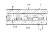
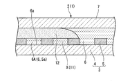
- FIG. 2 is a cross-sectional view taken along line AA in FIG. It is a figure for demonstrating the effect
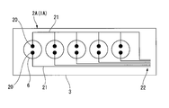
- It is a schematic diagram which shows the base material part of the array device for nucleic acid determination in the biological component analysis kit which concerns on 2nd Embodiment of this invention. It is a top view of the array device for nucleic acid quantification in the living body component analysis kit concerning a 3rd embodiment of the present invention. It is sectional drawing in the BB line of FIG.
- FIG. 1 is a perspective view of a biological component analysis kit according to the present embodiment.
- FIG. 2 is a cross-sectional view taken along line AA in FIG. 3 and 4 are diagrams for explaining the operation of the biological component analysis kit according to the present embodiment.
- the biological component analysis kit 1 is an example of an array device (a biological component quantification array device) for quantifying a biological component, and an array device (a nucleic acid quantification array device 2) that can quantify nucleic acids. ).
- an array device a nucleic acid quantification array device 2 that can quantify nucleic acids.
- the biological component analysis kit 1 according to the present embodiment shown in FIG. 1 is a kit that uses a substance selected from DNA, RNA, miRNA, mRNA, protein, exosome, liposome, and cell as a substance to be analyzed.
- the biological component analysis kit 1 according to the present embodiment is a kit that quantitatively measures the concentration of the analysis target substance contained in the biological component.
- the biological component analysis kit 1 includes an oil-based seal used together with the nucleic acid quantification array device 2, the detection reaction reagent 11 (see FIG. 3), and the nucleic acid quantification array device 2 shown in FIGS. And a stop liquid 12 (see FIG. 4).
- the array device 2 for nucleic acid quantification 2 includes a base material portion 3 having a plurality of wells 6, a cover portion 7, an injection port portion 8, a discharge port portion 9, and an aqueous solution 10. With.
- the base material portion 3 includes a substrate 4 and a micropore array layer 5.
- the substrate 4 is a plate-like member formed from a substantially transparent material.
- the material of the substrate 4 is, for example, resin or glass.
- the substrate 4 may be made of polystyrene or polypropylene.
- the substrate 4 only needs to have such a rigidity that it is not damaged during handling by the apparatus for conveying the nucleic acid quantification array device 2 or the manual operation of the operator.
- the microhole array layer 5 is a layer in which a plurality of through holes 5a are formed side by side.
- the layer thickness of the microhole array layer 5 is 3 ⁇ m, and a gap of 100 ⁇ m is provided between the microhole array layer 5 and the cover portion 7.
- Each through-hole 5a formed in the microhole array layer 5 has a cylindrical shape having a diameter of 5 ⁇ m and a length in the center line direction of 3 ⁇ m. (When the diameter of the through hole 5a is 5 ⁇ m and the length in the center line direction is 3 ⁇ m, the capacity of the minute space formed by one through hole 5a is about 100 femtoliters (fl)).
- each through hole 5a may be set as appropriate, but as an example, the volume of each through hole 5a is 10 picoliters or less.
- the distance between the center lines of each through-hole 5a should just be larger than the diameter of each through-hole 5a.
- Each through hole 5 a is arranged so as to form a triangular lattice shape with respect to the microhole array layer 5. Note that the arrangement of the through holes 5a is not particularly limited.
- the through hole 5a formed in the microhole array layer 5 and the surface 4a of the substrate 4 constitute a bottomed cylindrical well 6 having the substrate 4 as the bottom surface portion 6a.
- the material of the microhole array layer 5 may be resin, glass, or the like.
- the material of the microhole array layer 5 may be the same as the material of the substrate 4 or may be different from the material of the substrate 4.
- the microhole array layer 5 may be integrated with the same material as the substrate 4. Further, the microhole array layer 5 may be integrally formed of the same material as the substrate 4. Examples of the material of the microporous array layer 5 made of resin include cycloolefin polymer, silicon, polypropylene, polycarbonate, polystyrene, polyethylene, polyvinyl acetate, fluororesin, and amorphous fluororesin.
- the micropore array layer 5 may be formed on a glass substrate 4 using a cycloolefin polymer that is a hydrophobic resin.
- a hydrophobic material such as a hydrophobic resin
- the hydrophobic portion of the biomolecule to be detected is easily adsorbed and held by the hydrophobic micropore array layer 5.
- the biomolecules are efficiently collected in the micropore array layer 5 and the biomolecules in the well 6 can be easily detected.
- the hydrophobicity in this embodiment is defined as the contact angle with water in the contact angle test being in the range of 70 ° or more.
- the contact angle with water of the material used in this embodiment the contact angle with water of cycloolefin polymer (COP) is 85 °, and the contact with water of CYTOP which is a hydrophobic resin. The angle is about 110 °.
- COP cycloolefin polymer
- the micropore array layer 5 may be colored.
- the through-hole 5 a is formed by performing a process such as etching, embossing, or cutting on the solid pattern laminated on the substrate 4.
- the portion corresponding to the through holes 5 a of the microhole array layer 5 is subjected to processing such as etching, embossing, or cutting on the substrate 4. Formed by.
- the cover portion 7 is stacked on the base material portion 3 so as to cover the opening portions of the plurality of wells 6 with a gap between the base material portion 3 and the cover portion 7. Between the base material part 3 and the cover part 7, it becomes a flow path through which various liquids flow. In the present embodiment, various liquids flow from the inlet portion 8 toward the outlet portion 9 between the base material portion 3 and the cover portion 7.
- the inlet portion 8 is formed in the cover portion 7.
- the injection port portion 8 may be formed in the base material portion 3.
- the discharge port portion 9 communicates with the gap between the base material portion 3 and the cover portion 7 at a position away from the injection port portion 8.
- the liquid flows from the gap between the base material part 3 and the cover part 7 in the most distant portion when measured along the liquid flow path direction from the injection port part 8.
- the discharge port portion 9 is configured to leak out.
- the discharge port part 9 is connected to the base material part 3 or the cover part 7 so as to have a pipe shape communicated with the gap between the base material part 3 and the cover part 7 at a position away from the injection port part 8. It may be formed and sealable. In this case, it is possible to prevent the liquid existing between the base material part 3 and the cover part 7 from evaporating through the discharge port part 9.
- the discharge port 9 may be sealed by a seal or a plug that closes the discharge port 9.
- the aqueous solution 10 is filled between the base material portion 3 and the cover portion 7.
- the aqueous solution 10 is a liquid having a composition that can be mixed with a sample containing a substance to be analyzed.
- the aqueous solution 10 is a buffer solution that does not contain nucleic acid.
- the aqueous solution 10 only needs to be filled in each well 6. That is, a part or all of the flow path part between the base material part 3 and the cover part 7 may be filled with gas.
- the detection reaction reagent 11 is a reagent for performing a biochemical reaction on the template nucleic acid related to the analysis target substance.
- the biochemical reaction for the template nucleic acid is, for example, a reaction in which signal amplification occurs under conditions where the template nucleic acid is present.
- the detection reaction reagent 11 according to the present embodiment is a reagent that causes an enzyme reaction with respect to a template nucleic acid.
- the detection reaction reagent 11 is selected according to, for example, a method capable of detecting a nucleic acid. For example, reagents used in the Invader (registered trademark) method, the TaqMan (registered trademark) method, the fluorescent probe method, and other methods are included in the biological component analysis kit 1 as the detection reaction reagent 11 according to this embodiment.
- the oil-based sealing liquid 12 (see FIG. 4) is a solution that can be fed from the injection port 8 (see FIG. 1) between the base member 3 and the cover 7.
- the oil-based sealing liquid 12 can be selected from materials that are not mixed with the sample containing the analysis target substance.
- the oil-based sealing liquid 12 according to this embodiment is mineral oil.
- nucleic acid introduction method As a nucleic acid introduction method, a nucleic acid detection method, and a biological component analysis method according to the first embodiment of the present invention, a nucleic acid introduction method, a nucleic acid detection method, and a living body using the biological component analysis kit 1 according to this embodiment.
- a component analysis method is shown with the effect
- the aqueous solution 10 in the state before the use of the biological component analysis kit 1, as shown in FIG. 2, the aqueous solution 10 is preliminarily filled between the base material portion 3 and the cover portion 7, and the inlet portion 8. Both (refer FIG. 1) and the discharge port part 9 (refer FIG. 1) are sealed watertight. For this reason, the aqueous solution 10 between the base material part 3 and the cover part 7 is confined between the base material part 3 and the cover part 7 until the injection port part 8 or the discharge port part 9 is opened. .
- the volume of each well 6 is very small, if the aqueous solution 10 is filled in each well 6 at the time of manufacture of the nucleic acid quantification array device 2, before using the biological component analysis kit 1, Even if the vibrations are transmitted to the nucleic acid quantification array device 2, the aqueous solution 10 (well-filled aqueous solution) in each well 6 is not easily replaced by air.
- the aqueous solution 10 is filled in each well 6 in advance when the biological component analysis kit 1 (array device 2 for nucleic acid quantification) is manufactured, the user can use the biological component analysis kit 1. Since the step of degassing from the biological component analysis kit 1 is not required, the user can easily use the biological component analysis kit 1.
- a sample containing the substance to be analyzed is appropriately diluted with a known solvent.
- the dilution rate of the sample may be referred to the known dilution rate in digital PCR.
- the solvent for diluting the sample containing the substance to be analyzed has a composition that can be mixed with the aqueous solution 10 (well-filled aqueous solution) filled in each well 6. Further, in the step of diluting the sample containing the substance to be analyzed, the detection reaction reagent 11 is mixed at a specified concentration.
- the target substance to be analyzed is a nucleic acid
- the signal amplification reaction is performed by the invader method using the target target nucleic acid as a template nucleic acid.
- the template nucleic acid may be a nucleic acid produced by a living body or an artificial product such as a PCR (polymerase chain reaction) product.
- the template nucleic acid may be an antibody capable of capturing a biological substance or a labeled nucleic acid in a bead labeled with an antibody.
- part or all of the detection reaction reagent 11 is contained in the aqueous solution 10, part or all of the mixing of the detection reaction reagent 11 in the pretreatment is not necessary.
- the inlet 8 and the outlet 9 shown in FIG. 1 are opened, and the mixed solution X of the sample containing the template nucleic acid and the detection reaction reagent 11 for invader reaction passes through the inlet 8 and the base 3 and the cover.
- the liquid is fed into the gap between the parts 7 by, for example, a dispensing pipette.
- the mixed solution X of the sample and the detection reaction reagent 11 spreads in the gap between the base material portion 3 and the cover portion 7 so as to cover all of the plurality of wells 6 (see FIG. 3).
- the aqueous solution 10 is discharged from the discharge port 9 by feeding the mixed solution X of the sample and the detection reaction reagent 11 into the gap between the base 3 and the cover 7.
- the mixed solution X of the sample and the detection reaction reagent 11 has a color different from that of the aqueous solution 10
- the mixed solution X of the sample and the detection reaction reagent 11 is between the base portion 3 and the cover portion 7. It is possible to easily grasp which part of the liquid has been fed.
- a plurality of wells 6 formed by the substrate 4 and the micropore array layer 5 are arranged in the flow path constituted by the base material portion 3 and the cover portion 7.
- the aqueous solution 10 (well-filled aqueous solution) filled in the plurality of wells 6 is maintained while being held on the inner surface of each well 6. Therefore, the mixed solution X of the sample and the detection reaction reagent 11 does not replace the aqueous solution 10 filled in the plurality of wells 6, and the mixed solution X is overlaid on the aqueous solution 10.
- the aqueous solution 10 and the mixed solution X can be easily mixed with each other, after the mixed solution X is overlaid on the aqueous solution 10, the solute in the mixed solution X becomes the aqueous solution 10 (well filling). Diffuses into an aqueous solution).
- the oil-based sealing liquid 12 is fed from the inlet port 8 (see FIG. 1) into the flow path constituted by the base material part 3 and the cover part 7.
- the oil-based sealing liquid 12 seals the plurality of wells 6 with a plurality of independent nucleic acids by sealing the liquid in the plurality of wells 6 (well-filled aqueous solution) in a state where the mixed solution X is diffused into the aqueous solution 10. Let it be reaction container 6A.
- the oil-based sealing liquid 12 pushes the liquid outside the plurality of wells 6 from the discharge port portion 9 within the gap between the base material portion 3 and the cover portion 7.
- one or zero template nucleic acid is present in each of the nucleic acid detection reaction vessels 6A. If the concentration of the sample is too high, a plurality of template nucleic acids may enter one of the nucleic acid detection reaction vessels 6A.
- the detection reaction reagent 11 for invader reaction and the template nucleic acid are enclosed in the well 6 (in the nucleic acid detection reaction vessel 6A) according to the concentration of the template nucleic acid.
- the nucleic acid quantification array device 2 is incubated in an oven at 62 ° C. for a predetermined time.
- signal amplification performed isothermally (isothermal reaction) in the invader reaction suitably proceeds in the nucleic acid detection reaction vessel 6A.
- the nucleic acid quantification array device 2 in which the detection reaction reagent 11 for invader reaction and the template nucleic acid are enclosed in the well 6 (in the nucleic acid detection reaction vessel 6A) is taken out of the oven after a predetermined time,
- the number of nucleic acid detection reaction vessels 6A having fluorescence and the fluorescence amount of the nucleic acid having fluorescence are measured.
- the presence / absence of fluorescence in the nucleic acid detection reaction vessel 6A may be a threshold value with a fluorescence amount exceeding a predetermined S / N ratio with respect to autofluorescence.
- the signal amplification by the invader method proceeds suitably and the signal is saturated in each nucleic acid detection reaction vessel 6A, the fluorescence amount in the nucleic acid detection reaction vessel 6A having fluorescence is unlikely to vary greatly.
- the liquid containing the template nucleic acid is the injection port 8. Is introduced into the gap between the base portion 3 and the cover portion 7, excess solution outside the plurality of wells 6 in the aqueous solution 10 is discharged from the discharge port portion 9, and a plurality of the aqueous solutions 10 are discharged.
- the template nucleic acid is transferred to the aqueous solution 10 (well-filled aqueous solution 10) in the well 6 by diffusion.
- each of the template nucleic acids is transferred to each well 6. Air bubbles are unlikely to enter the well 6.
- the nucleic acid detection method since the possibility of bubbles entering each well 6 is extremely low, in the nucleic acid detection method, the biological component analysis method, the nucleic acid quantification array device 2 and the biological component analysis kit 1 according to the present embodiment, the nucleic acid
- the possibility that the number of the nucleic acid detection reaction containers 6A capable of detecting the difference in presence of bubbles will be kept low.
- the volume of each well 6 is very small, the volume of bubbles in the well 6 cannot be ignored and the progress of the nucleic acid detection reaction may vary from well 6 to each other.
- a detection system for detecting visible light emission, color development, or the like as a signal may be applied.
- a structure which concerns on this embodiment in order to analyze protein.
- a molecule that specifically binds to the target protein is modified with a nucleic acid such as a DNA strand.
- the presence or absence of the target protein can be analyzed by the signal detection procedure in this embodiment by designing an oligo of the invader method using a nucleic acid such as a DNA strand used for modification as a template nucleic acid.
- the substance to be analyzed may be any of DNA, RNA, miRNA, mRNA, or protein, for example.
- the substance to be quantified by the nucleic acid quantification array device 2 and the biological component analysis kit 1 according to the present embodiment is a nucleic acid such as a DNA chain used for modification, and the substance modified by this nucleic acid is indirectly quantified. Is done.
- a substance that modifies a molecule that specifically binds to a target protein is not limited to a DNA strand, and any substance that generates a signal for detection may be used. Examples thereof include fluorescent beads and HPR (horseradish peroxidase).
- a substance that specifically binds to a substance modified with the template nucleic acid as a labeling substance (a partner substance) is a nucleic acid detection method, biological component analysis method, nucleic acid quantification array device 2 according to this embodiment. It is also possible to analyze using the biological component analysis kit 1.
- the substance modified with the template nucleic acid may include at least one of a DNA chain, enzyme, particle, antibody, and liposome different from the template nucleic acid.
- a liquid containing a biological substance that causes a fluorescence, visible light, or color reaction in the well 6 is formed between the inlet 8 and the gap between the base 3 and the cover 7.
- This living body-derived substance can be quantified by being introduced into.
- liposomes, exosomes, and cells are listed as examples of biologically derived substances that are quantified as the analysis target substance.
- the labeling substance that performs such labeling include substances that include, as constituent elements, a low-molecular ligand or an antibody that specifically binds to a biological substance that is an analysis target substance.
- a signal emitted from the biological substance to be analyzed itself is detected by using the biological component quantifying array device according to the present embodiment.
- Quantification of derived substances is possible.
- a biological substance a cell in which a fluorescent protein expression cassette including a promoter for expressing a fluorescent protein and a target gene is incorporated into a chromosome and other gene regions by genetic recombination, or the above fluorescent protein Examples thereof include a cell carrying a plasmid containing an expression cassette.
- the fluorescent protein is expressed by mixing a predetermined reagent that promotes transcription with respect to the fluorescent protein expression cassette and the above-described cells in the well 6, so that cells that emit fluorescence can be quantified.
- the fluorescent protein expression cassette may be constructed as an expression cassette for a reporter gene that is expressed in response to the expression of a gene other than the fluorescent protein.
- Quantification can be performed using the biological component quantification array device according to the present embodiment.
- the well 6 sealed with the oil-based sealing liquid 12 becomes an independent signal detection container for detecting a signal from the biological substance, and can quantify the biological substance.
- the quantification method as described above, it is possible to quantify viruses and cells existing in the living body as the biologically derived substance. It is also possible to qualitatively check the presence or absence.
- the biological component quantification array device can also quantify substances that are not biological components.
- the biological component quantification device can also be used as a virus particle quantification device.
- signal amplification by an enzyme reaction using a signal amplification reaction reagent different from the invader method may be employed.
- This signal amplification reaction reagent may be mixed with a sample containing a substance to be analyzed as in the above embodiment.
- both the bottom surface portions 6a and the cover portions 7 of the plurality of wells 6 are formed of a substantially transparent material, but the bottom surface portions 6a of the plurality of wells 6 As long as at least one of the cover part 7 has optical transparency, optical detection of fluorescence, light emission, absorbance, etc. in the plurality of wells 6 can be performed.
- a suitable configuration is disclosed when the sample containing the template nucleic acid is aqueous (polar).
- the sample containing the template nucleic acid is oily (nonpolar)
- the aqueous solution 10 instead of this, a nonpolar sealing liquid containing an organic solvent or the like is preferably employed.
- a polar substitution solution is employed instead of the oily sealing solution 12 shown in the present embodiment. It is preferable. The selection of these solutions takes into account the solubility of the sample containing the template nucleic acid in the solvent and the type of solvent selected according to the stability of the template nucleic acid and the analyte.
- the sealing liquid when the sample containing the template nucleic acid is an aqueous solution, mineral oil can be selected as the sealing liquid.
- the sealing liquid can be water or an aqueous buffer. Can be selected.
- nucleic acids are polar molecules, they are poorly soluble in non-polar solvents.
- labeled nucleic acids for quantification of analytes are bound to the analytes.
- the sample containing the template nucleic acid may be diluted with a nonpolar solvent.
- FIG. 5 is a schematic diagram showing a base material part of an array device for nucleic acid quantification in the biological component analysis kit according to the present embodiment.
- the same components as those disclosed in the first embodiment described above are denoted by the same reference numerals as those in the first embodiment, and redundant descriptions are omitted.
- the biological component analysis kit 1A uses the nucleic acid quantification array device 2A that can perform electrochemical measurement in the well 6 as the nucleic acid quantification array device 2 of the first embodiment.
- the configuration differs from the first embodiment in that it is provided instead.
- the nucleic acid quantification array device 2A according to the present embodiment includes the base material section 3, the well 6, the cover section 7, the aqueous solution 10, the injection port section 8, and the discharge port section 9 disclosed in the first embodiment. ing.
- the plurality of wells 6 according to the present embodiment have electrodes 20 on the bottom surface portion 6a.
- the base material portion 3 according to the present embodiment includes a wiring 21 connected to the electrode 20 in the well 6 and a connector 22 for connecting the wiring 21 to the detection circuit.
- the electrode 20 can detect, for example, a change in potential of the solution in the well 6 and a change in electrical resistance.
- the wiring 21 and the connector 22 are formed on the base member 3 by, for example, printing.
- the wiring 21 and the connector 22 are patterned on the outer surface of the substrate 4 so as to be sandwiched between the substrate 4 and the microhole array layer 5.
- the materials of the electrode 20, the wiring 21, and the connector 22 are not particularly limited.
- the nucleic acid can be quantified using a pH change or potential change corresponding to the presence or absence of the template nucleic acid as a signal.
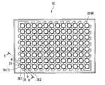
- FIG. 6 is a plan view of an array device for nucleic acid quantification in the biological component analysis kit according to the present embodiment.
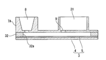
- FIG. 7 is a sectional view taken along line BB in FIG.
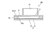
- a biological component analysis kit 1B according to this embodiment shown in FIG. 6 includes a base material portion 3, a microporous array layer 5 having wells, a cover portion 7, an aqueous solution 10, and an injection port portion 8 disclosed in the first embodiment. And a discharge port portion 9. Furthermore, the biological component analysis kit 1 ⁇ / b> B according to the present embodiment further includes a waste liquid container portion 31 that communicates with the discharge port portion 9.
- the waste liquid container part 31 has a space in which liquid flows from the gap between the base part 3 and the cover part 7 through the discharge port part 9 and is stored outside the cover part 7.
- a cover portion 7A in which an inlet portion 8, a discharge port portion 9, and a waste liquid container portion 31 are formed is provided.
- a plurality (96 in this embodiment) of independent nucleic acid quantification array devices 2B1, 2B2,... B96 have The array devices for nucleic acid quantification 2B1, 2B2,... B96 are arranged in a square lattice and connected to each other.
- the plurality of independent nucleic acid quantification array devices 2B1, B2,... B96 are water-tightly separated by a spacer member 32 that connects the base portion 3 and the cover portion 7A.
- the spacer member 32 according to the present embodiment holds the micropore array layer 5 and the cover portion 7A so that the size of the gap between the micropore array layer 5 of the base material portion 3 and the cover portion 7A is 100 ⁇ m. To do.
- the spacer member 32 according to the present embodiment has a through hole 32 a that connects the injection port portion 8 and the discharge port portion 9 and surrounds each through hole 5 a of the microhole array layer 5.
- the waste liquid treatment is easy.
- the biological component analysis kit 1B according to the present embodiment may not have the aqueous solution 10. It should be noted that various liquids may be injected from the discharge port 9 and excess liquid may be discharged from the injection port 8.
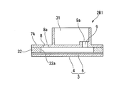
- FIG. 8 is a cross-sectional view showing the configuration of this modification.
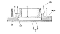
- the base material portion 3 is defined as the lower side and the cover portion 7 ⁇ / b> A is defined as the upper side in the thickness direction of the base material portion 3, the inlet opening end 8 a in the injection port portion 8. Is located below the waste liquid container side opening end 9 a in the discharge port 9. Further, the waste liquid container side opening end 9 a in the discharge port 9 is located above the bottom surface of the waste liquid container part 31.
- the waste liquid container side opening end 9 a in the discharge port portion 9 is above the bottom surface of the waste liquid container portion 31, so that the liquid that has entered the waste liquid container portion 31 passes through the discharge port portion 9. It is difficult to back flow into the gap between the portion 3 and the cover portion 7A.
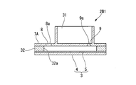
- FIG. 9 is a cross-sectional view showing the configuration of this modification.
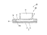
- the base material portion 3 is defined as the lower side and the cover portion 7 ⁇ / b> A is defined as the upper side in the thickness direction of the base material portion 3, the inlet opening end 8 a in the injection port portion 8. Is located above the waste liquid container side opening end 9 a in the discharge port portion 9.
- various liquids are fed from the inlet opening end 8a until the liquid enters the waste liquid container part 31 from the waste liquid container side opening end 9a of the discharge outlet part 9, and then the inlet opening end 8a is opened.
- the liquid in the inlet port 8 is placed between the base member 3 and the cover portion 7A. Enter further into the gap. Further, when the mixed solution X of the sample and the detection reaction reagent 11 and the oil-based sealing liquid 12 are fed into the gap between the base material portion 3 and the cover portion 7A through the inlet port 8, the waste liquid container is discharged from the outlet port 9. A part of the liquid pushed out to the portion 31 tries to return to the gap between the base portion 3 and the cover portion 7A from the discharge port portion 9 by gravity, but antagonizes the mass of the liquid in the injection port portion 8. Thus, the back flow of the liquid from the waste liquid container portion 31 is suppressed.
- FIG. 10 is a cross-sectional view showing the configuration of this modification.
- the opening area of the discharge port 9 is smaller than the opening area of the injection port 8.
- the opening area of the discharge port portion 9 is set to an area where a pipe resistance can be obtained so that the liquid cannot pass through the discharge port portion 9 unless the liquid feeding pressure from the injection port portion 8 is applied.
- the specific opening area of the discharge port 9 may be determined according to the composition of the liquid expected to be discharged from the discharge port 9.
- liquid can be transferred from the inlet 8 to the waste liquid container 31 through the outlet 9 from the gap between the base 3 and the cover 7A during liquid feeding from the inlet 8.
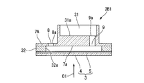
- FIG. 11 is a cross-sectional view showing the configuration of this modification.
- part which comprises the bottom face 31a of the waste-liquid container part 31 is thick compared with the biological component analysis kit 1B of the said 3rd Embodiment.
- the injection port in the injection port portion 8 is defined.
- the position of the opening end 8 a is below the waste liquid container side opening end 9 a in the discharge port portion 9.
- the position of the inlet opening end 8a in the inlet 8 may be above the waste liquid container side opening end 9 a in the outlet 9. In this case, the present modification has the same effect as the second modification.
- the bottom surface of the waste liquid container portion 31 is detected when fluorescence, light emission, color development, or the like is detected from the lower side (lower surface) in the thickness direction of the base material portion 3 (the direction indicated by reference numeral D1 in FIG. 11). Since the site
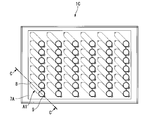
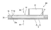
- FIG. 12 is a plan view showing the configuration of this modification.
- 13 is a cross-sectional view taken along the line CC of FIG.
- reaction and detection are performed in an area A1 provided between the inlet 8 and the outlet 9 and not overlapping the waste liquid container 31 in the thickness direction of the base 3. Is possible.
- this region A1 from the lower side (lower surface) in the thickness direction of the base material part 3 (the direction indicated by reference numeral D1 in FIG. 13) or from the upper side (upper surface) in the thickness direction of the base material part 3 (reference numeral in FIG. 13).
- a region capable of detecting fluorescence, light emission, color development, or the like is provided.
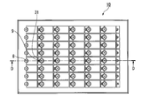
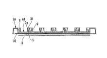
- FIG. 14 is a plan view showing the configuration of this modification.
- 15 is a cross-sectional view taken along the line DD in FIG.
- FIG. 16 is a perspective view showing a cross section taken along line DD of FIG.
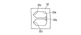
- FIG. 17 is a plan view showing the spacer member 32 in the present modification.
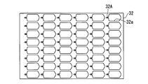
- 18A, 18B, and 18C are plan views showing other configurations of the spacer member 32.
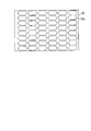
- FIG. 19 is a plan view of the base material portion 3 including the microhole array layer 5 of the present modification.
- the injection port 8 is formed in a funnel shape, and a pipette tip or the like for injecting liquid can be smoothly guided to the injection port 8.
- the position of the inlet port 8 may correspond to the center position of each well in the existing 96 well plate. That is, in the present modification, the injection port portions 8 may be arranged at 48 positions among the central positions (96 positions) of each well in the 96 well plate. Thereby, it is possible to easily correspond to the dispensing operation in the existing ELISA apparatus.
- the discharge port portion 9 connected to the waste liquid container portion 31 is arranged such that the waste liquid container side opening end 9a of the discharge port portion 9 is above the bottom surface of the waste liquid container portion 31 as in the first modification. Molded.
- the spacer member 32 connects the inlet 8 and the outlet 9 shown in FIG. 15, and stores a liquid such as a reagent between the inlet 8 and the outlet 9. Create a gap that can be
- the spacer member 32 includes an inlet portion 32x corresponding to the position of the inlet portion 8, an outlet portion 32z corresponding to the position of the outlet portion 9, and the inlet portion 32x and the outlet portion. As long as it has the flow path part 32y which connects 32z, it is not restricted to the structure shown in FIG.
- the flow path portion 32y is provided so as to connect two of the regions A1 (see FIG. 19) that do not overlap the waste liquid container portion 31. Yes.
- the inlet portion 32x and the opposite of the inlet portion 32x with a region A1 (see FIG. 19) not overlapping the waste liquid container portion 31 interposed therebetween.
- One end of the flow path part 32y is provided at the position, the other end of the flow path part 32y is routed to the inlet part 32x side, and the outlet part 32z is located in the vicinity of the inlet part 32x.
- a recess 32A for holding a solid reagent may be formed in the vicinity of the inlet 8 in the spacer member 32.
- various reagents to be mixed immediately before detection may be held.
- a liquid such as a reagent flows through the inlet port 8
- the reagent disposed in the recess is dissolved in the liquid, thereby causing a reaction.
- a fluorescence, color, or luminescence reaction can be detected in a substantially rectangular region A1 (see FIG. 15) located between the inlet 8 and the outlet 9.
- both the inlet 8 and the outlet 9 may be funnel-shaped.
- the inner surface of the injection port 8 is formed of a plurality of planes, and the injection port 8 is formed in a tapered shape so that it gradually narrows toward the base material 3 side. You may be comprised (so that the diameter of the injection port part 8 may become small).
- Various liquids may be injected from the discharge port portion 9 and excess liquid may be discharged from the injection port portion 8.
- FIG. 25 is a cross-sectional view showing the configuration of this modification.
- the inlet 8 has a funnel shape.
- the inner shape of the inlet port 8 is configured to be relatively large so that liquid does not remain in the inlet port 8 due to capillary action.
- the liquid such as the reagent is fed by the weight of the liquid such as the reagent.
- each well 6 (see the first embodiment) of the microhole array layer 5 can be individually sealed.
- the specific gravity of the oil may be about 1.8, for example.
- FIG. 26 is a plan view showing the configuration of this modification.
- 27 is a cross-sectional view taken along line EE in FIG.
- the waste liquid container portion 31 is also configured on the inlet portion 8 side.
- the waste liquid container part 31 configured on the inlet part 8 side can store the liquid overflowing from the inlet part 8 when the liquid is fed from the outlet part 9 to the inlet part 8 side.
- a liquid containing a detection target, a reagent, and the like is sent from the inlet 8 and then oil is sent from the outlet 9.
- the reagent and oil overflowing from the injection port portion 8 are stored in a waste liquid container portion 31 provided on the injection port portion 8 side.
- the liquid stored in the waste liquid container part 31 provided on the inlet part 8 side is not mixed with the liquid stored in the waste liquid container part 31 provided on the discharge port part 9 side. It should be noted that various liquids may be injected from the discharge port 9 and excess liquid may be discharged from the injection port 8.
- FIG. 28 is a cross-sectional view showing a configuration of this modification.
- the present modification is different from the biological component analysis kit 1B disclosed in the third embodiment in that the cover portion 7A is made of a light-impermeable material.
- the cover portion 7A may be made of a material that selectively transmits light of a specific wavelength.
- the non-transmission in this modification may be to absorb light having a specific wavelength or reflect light having a specific wavelength.
- the cover portion 7A may have a configuration that transmits visible light but does not transmit ultraviolet light.
- the cover portion 7A transmits the excitation light for detecting the fluorescence, but does not transmit the fluorescence generated by the excitation light.
- the cover portion 7A transmits the excitation light for detecting the fluorescence, but does not transmit the fluorescence generated by the excitation light.
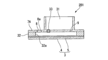
- FIG. 29 is a cross-sectional view showing a configuration of this modification.
- the cover portion 7A has a filter 33 for moving the air bubbles that have entered between the micropore array layer 5 and the cover portion 7A to the outside of the cover portion 7A.
- the filter 33 has a structure that can transmit gas but cannot transmit liquid.
- the injection port portion 8 and the discharge port portion 9 are provided as in the third embodiment.
- the filter 33 provided in the cover portion 7 ⁇ / b> A is disposed downstream of the inlet portion 8 and in the vicinity of the inlet portion 8. Thereby, the air bubbles mixed in the reagent, the oil and the like are captured by the filter 33 before reaching the region used for detection in the micropore array layer 5.
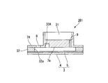
- FIG. 30 is a cross-sectional view showing the configuration of this modification.
- a recess 33A for storing bubbles is formed in the cover portion 7A.
- the position of the recess 33 ⁇ / b> A formed in the cover portion 7 ⁇ / b> A is preferably downstream of the injection port portion 8 and in the vicinity of the injection port portion 8, similarly to the above-described modification 10. Even with such a configuration, the same effects as those of Modification 10 described above can be obtained. Further, in this modification, larger bubbles can be captured more efficiently than when the filter 33 disclosed in the modification 10 is provided.
- FIG. 31 is a cross-sectional view showing the configuration of this modification.
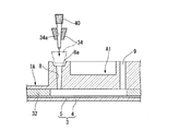
- the adapter 34 is provided with a through-hole 34 a that is in contact with the inlet opening end 8 a of the inlet 8 and through which the pipette tip 40 can be inserted into the inlet 8.
- the adapter 34 is used in a state where it is combined with a pipette tip 40 that is used when a reagent or oil is fed.
- the outer shape of the adapter 34 is not particularly limited.
- the external shape of the adapter 34 according to the present embodiment is a truncated cone shape whose diameter gradually decreases toward the tip of the pipette tip 40 when the pipette tip 40 is attached to the adapter 34.
- the adapter 34 when the adapter 34 is attached to the pipette tip 40 and the tip of the pipette tip 40 is inserted into the inlet 8, the adapter 34 contacts the inlet opening 8 a. Thereby, the cover part 7A is pushed to the base material part 3 side. As a result, the volume of the gap between the cover portion 7A and the base material portion 3 is reduced, so that the liquid between the cover portion 7A and the base material portion 3 is slightly from the injection port portion 8 and the discharge port portion 9. Leaks out.
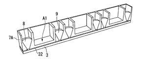
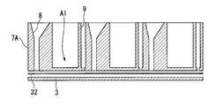
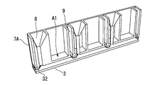
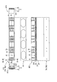
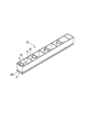
- FIG. 32A is a perspective view showing a configuration of a biological component analysis kit 1F of the present modification.
- FIG. 32B shows a plan view 1F1 (corresponding to a plan view 7Aa of the cover portion 7A) in the biological component analysis kit 1F, a sectional view 1F2 in the AA section, a sectional view 1F3 in the BB section, and a side view. 1F4, a plan view of the seal member 101, and a bottom view 7Ab of the cover portion 7A are shown.
- the biological component analysis kit 1F of the present modified example is similar to the modified example 6 described above in that the fluorescence in the micropore array layer 5 is not affected by the presence or absence of waste liquid or the amount of waste liquid.
- a micro-hole array between the inlet 8 and the outlet 9 so as not to overlap the waste liquid container 31 in the thickness direction of the base 3 so that light emission or color development can be detected. It has area
- the injection port 8 is formed in a funnel shape, and a pipette tip or the like for injecting liquid can be smoothly guided to the injection port 8.
- the discharge port part 9 connected to the waste liquid container part 31 in this modified example has a funnel shape like the injection port part 8, and the discharge port part 9 It has a shape that can smoothly guide pipette tips and the like.
- the liquid containing the detection target, the reagent, and the like is fed from the injection port 8 and then the oil is fed from the discharge port 9. .
- the liquid flows into the waste liquid container 31 through the outlet 9 through the gap between the cover 7 ⁇ / b> A and the base 3.
- the seal member 101 connects the inlet port 8 and the outlet port 9 shown in FIG. 32B to each other like the spacer member 32 in the other modified examples.
- a gap in which a liquid such as a reagent can be stored is generated.
- the seal member 101 includes an inlet portion corresponding to the position of the inlet portion 8, an outlet portion corresponding to the position of the outlet portion 9, and an inlet portion. As long as it has the flow path part which connects an exit part and an exit part, it is not restricted to the structure shown to FIG. 32B.
- a fluorescence, color, or luminescence reaction can be detected in a substantially rectangular area A1 (see FIG. 32B) located between the inlet 8 and the outlet 9.
- one inlet portion 8, one area A1, one outlet portion 9 and one waste liquid container portion 31 is regarded as one unit. It can also be used. That is, the biological component analysis kit 1F according to the present modification may be used as a single-row kit, or may be separated from the single-row kit and used as an individual analysis kit.
- FIG. 32A shows a one-row kit.
- the biological component analysis kit 1F according to this modification may have a 96-hole shape.
- the position of the injection port 8 may correspond to the center position of each well in the existing 96 well plate. That is, in the present modification, the injection port portions 8 may be arranged at 48 positions among the central positions (96 positions) of each well in the 96 well plate. Thereby, it is possible to easily correspond to the dispensing operation in the existing ELISA apparatus.
- FIG. 32B shows a configuration in which the seal member 101 is provided separately from the base material portion 3 formed from the substrate 4 and the micropore array layer 5, but the seal member 101 and the base material portion 3 are integrally formed. You may have the structure made.
- FIG. 33A is a perspective view showing a configuration of a biological component analysis kit 1G of the present modification.
- 33B shows a plan view 1G1 (corresponding to a plan view 7Aa of the cover portion 7A) in the biological component analysis kit 1G, a sectional view 1G2, a left side view 1G3, and a right side view 1G4 in the AA cross section.
- a plan view of the member 101 and a bottom view 7Ab of the cover portion 7A are shown.
- the biological component analysis kit 1G according to the present modified example is similar to the modified example 6 described above in that the fluorescence in the micropore array layer 5 is not affected by the presence or absence of the waste liquid or the amount of the waste liquid.
- a micro-hole array between the inlet 8 and the outlet 9 so as not to overlap the waste liquid container 31 in the thickness direction of the base 3 so that light emission or color development can be detected. It has area
- the injection port 8 is formed in a funnel shape, and a pipette tip or the like for injecting liquid can be smoothly guided to the injection port 8.
- the inlet opening end 8a in the injection port portion 8 is defined. Is located below the waste liquid container side opening end 9 a in the discharge port 9. Further, the waste liquid container side opening end 9 a in the discharge port 9 is located above the bottom surface of the waste liquid container part 31.
- various liquids are fed from the inlet opening end 8a until the liquid enters the waste liquid container part 31 from the waste liquid container side opening end 9a of the discharge outlet part 9, and then the inlet opening end 8a is opened.
- the liquid amount from the inlet opening end 8a is limited to the liquid amount in the outlet port 9 as the upper limit. Flows backward. For this reason, even if there is a bubble in the vicinity of the inlet opening end 8a, the bubble is caused to flow by the back flow of the liquid and is pushed out from the inlet opening end 8a. In the present modification, bubbles are unlikely to remain between the base material portion 3 and the cover portion 7A in the vicinity of the injection port portion 8.
- the waste liquid container side opening end 9 a in the discharge port portion 9 is above the bottom surface of the waste liquid container portion 31, so that the liquid that has entered the waste liquid container portion 31 passes through the discharge port portion 9. It is difficult to back flow into the gap between the portion 3 and the cover portion 7A.
- the waste liquid container 31 is formed so that the volume of the waste liquid container 31 is larger than the total amount of the reagent and oil injected. Therefore, there is no possibility that the liquid leaks from the waste liquid container part 31 to the outside of the biological component analysis kit 1G when the reagent and oil are injected.
- the sealing member 101 connects the inlet port 8 and the outlet port 9 shown in FIG. 33B to connect the inlet port 8 and the outlet port 9 as in the thirteenth modified example.
- a gap in which a liquid such as a reagent can be stored is generated between them.
- the seal member 101 includes an inlet portion corresponding to the position of the inlet portion 8, an outlet portion corresponding to the position of the outlet portion 9, and a flow path connecting the inlet portion and the outlet portion. If it has a part, it will not be restricted to the structure shown to FIG. 33B.
- a fluorescence, color, or luminescence reaction can be detected in a substantially rectangular region A1 (see FIG. 33B) located between the inlet 8 and the outlet 9.
- one inlet portion 8, one area A1, one outlet portion 9 and one waste liquid container portion 31 is regarded as one unit.
- the biological component analysis kit 1G of the present modification may be used as a single-row kit, or may be separated from the single-row kit and used as an individual analysis kit.
- FIG. 33A shows a one-row kit, but the kit may have a 96-hole shape, as shown in another modification.
- the position of the injection port 8 may correspond to the center position of each well in the existing 96 well plate. That is, in the present modification, the injection port portions 8 may be arranged at 48 positions among the central positions (96 positions) of each well in the 96 well plate. Thereby, it is possible to easily correspond to the dispensing operation in the existing ELISA apparatus.
- FIG. 33B shows a configuration in which the seal member 101 is provided separately from the base material portion 3 formed from the substrate 4 and the micropore array layer 5, but the seal member 101 and the base material portion 3 are integrally formed. You may have the structure made.
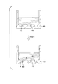
- FIG. 34 is a diagram for explaining the operation of this modification.
- a single-row kit can be cut out and used for each unit.
- a container 103 which is integrally formed and has a beaker shape or a tube shape can also be used.
- the flow path is not formed, and the operation of introducing the biological component 102 such as a nucleic acid into the well 6 and the detection operation can be performed in a state where the batch type container 103 is filled with the liquid.
- the container 103 can be provided with a plurality of wells 6.
- the well 6 is filled with the aqueous solution 10 in advance during the manufacturing process, the user of the kit can perform an analytical test on site. Then, the biological component 102 such as a nucleic acid to be detected diffuses into the well 6, and the biological component 102 is introduced into the well 6 to enable detection.
- the well 6 is not filled in advance with the aqueous solution 10 in the manufacturing process, it is difficult for the user of the kit to degas bubbles that have entered the well 6 when performing an on-site analysis test. It is. Therefore, in this modification, it is preferable that the well 6 is filled with the aqueous solution 10 in advance during the manufacturing process. It should be noted that the operation of introducing a biological component such as a nucleic acid, analysis operation such as detection and observation in the present modification can be performed in the same manner as in the above-described embodiment.
- the nucleic acid introduction method in the above-described embodiment, is shown as an example.
- the biological component introduction method includes DNA, RNA, miRNA, mRNA, protein, exosome, liposome, and cells. There may be.
- the biological component introduction method according to the present embodiment can be performed in the same manner as the above-described nucleic acid introduction method, and the biological component is not limited to only nucleic acids.
- DNA, RNA, miRNA, mRNA, protein, exosome, liposome, and Biological components including cells and the like may be targeted, and the analysis target is not limited to the above-described embodiment.
- nucleic acid introduction method biological component introduction method
- biological component analysis method biological component analysis method
- nucleic acid quantification array device 2 nucleic acid quantification array device 1
- biological component analysis kit 1 biological component analysis kit 1
- CYTOP registered trademark
- Asahi Glass which is a hydrophobic resin
- CYTOP manufactured by Asahi Glass
- the base material part 3 which has 1 million was produced.
- a layer formed on the substrate 4 by spin coating CYTOP (registered trademark) was formed by photolithography, thereby forming the microhole array layer 5 disclosed in the above embodiment.
- the thickness of the layer formed on the substrate 4 by spin coating CYTOP (registered trademark) is 3 ⁇ m.
- the cover glass was installed on the base material part 3 as the cover part 7 so that the clearance gap with the base material part 3 might be set to 100 micrometers.
- the spacer which consists of adhesive tapes was distribute
- the aqueous liquid which does not contain a nucleic acid is sent as a replacement liquid, and a hole with a diameter of 5 ⁇ m and a gap between the base material part 3 and the cover part 7 The whole was filled with an aqueous liquid.
- the composition of the aqueous liquid is 20 ⁇ M MOPS pH 7.5, 15 mM NaCl, 6.25 mM MgCl 2 .
- Invader reaction reagent (2 ⁇ M allele probe, 1 ⁇ M invader oligo, 1 ⁇ M FAM labeled arm, 20 ⁇ M MOPS pH 7.5, 15 mM NaCl, 6.25 mM MgCl 2 , 50 U / ⁇ L Chrybase (registered trademark)) is mixed with artificially synthesized DNA.
- the mixed solution X was fed into the gap between the base material portion 3 and the cover portion 7.
- the artificially synthesized DNA is mixed so that the concentration of the artificially synthesized DNA is 30 pM so that one molecule enters one of the holes of 5 ⁇ m in diameter formed in the base part 3.
- a cylindrical micropore having a diameter of 5 ⁇ m and a height of 3 ⁇ m has a volume of 59 fL, and assuming that it follows a Poisson distribution, at an artificially synthesized DNA concentration of 30 pM, it is estimated that 65% of 1 million micropores will enter micropores.
- FC-40 SIGMA was fed into the gap between the base part 3 and the cover part 7 as the oil-based sealing liquid 12, and the diameter was 5 ⁇ m.
- One million nucleic acid detection reaction vessels 6A were configured by sealing the holes.
- the array device 2 for nucleic acid quantification of this example having 1 million independent nucleic acid detection reaction vessels 6A is incubated in an oven at 62 ° C., taken out after 15 minutes, photographed with a fluorescence microscope, and taken in each hole. The fluorescence intensity was observed.
- the nucleic acid detection reaction vessel 6A after the reaction includes a fluorescence microscope (Zeiss, AX10), a light source (LEJ, FluoArc001.26A Usable with HBO 10), a sensor (Hamamatsu Photonics, EM-CCD C9100), a filter ( Olympus, U-MNIBA2), analysis software (Hamamatsu Photonics, AQUACOSMOS 2.6: exposure time 488 ms, EM gain 120, offset 0, binning ⁇ 1) The number of nucleic acid detection reaction vessels 6A that emit fluorescence with an N ratio was counted.
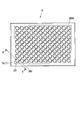
- FIG. 35 is a photograph showing the biological component analysis results in this example.
- fluorescence emission by the invader reaction was observed from approximately 65% of the total number of nucleic acid detection reaction vessels 6A. This is consistent with the above estimation based on the Poisson distribution, and the invader reaction reagent and the artificially synthesized DNA are suitably contained in the nucleic acid detection reaction vessel 6A so that the invader reaction proceeds, corresponding to the concentration of the artificially synthesized DNA. It shows that the measurement result was obtained.
Landscapes
- Chemical & Material Sciences (AREA)
- Health & Medical Sciences (AREA)
- Life Sciences & Earth Sciences (AREA)
- Engineering & Computer Science (AREA)
- Organic Chemistry (AREA)
- Zoology (AREA)
- Wood Science & Technology (AREA)
- General Health & Medical Sciences (AREA)
- Bioinformatics & Cheminformatics (AREA)
- Biotechnology (AREA)
- Genetics & Genomics (AREA)
- Microbiology (AREA)
- Biochemistry (AREA)
- Molecular Biology (AREA)
- Immunology (AREA)
- Analytical Chemistry (AREA)
- Proteomics, Peptides & Aminoacids (AREA)
- General Engineering & Computer Science (AREA)
- Biomedical Technology (AREA)
- Physics & Mathematics (AREA)
- Hematology (AREA)
- Biophysics (AREA)
- Sustainable Development (AREA)
- Cell Biology (AREA)
- Urology & Nephrology (AREA)
- Clinical Laboratory Science (AREA)
- Chemical Kinetics & Catalysis (AREA)
- Food Science & Technology (AREA)
- Medicinal Chemistry (AREA)
- General Physics & Mathematics (AREA)
- Pathology (AREA)
- Dispersion Chemistry (AREA)
- Apparatus Associated With Microorganisms And Enzymes (AREA)
- Measuring Or Testing Involving Enzymes Or Micro-Organisms (AREA)
Abstract
生体成分定量用アレイデバイスであって、複数のウェルを有する基材部と、前記基材部との間に隙間を有して前記複数のウェルの開口部分を覆うように前記基材部に重ねられたカバー部と、前記基材部と前記カバー部との間の前記隙間に連通された注入口部と、前記注入口部から離れた位置に形成され、前記基材部と前記カバー部との間の前記隙間に連通された排出口部と、を備え、前記基材部と前記カバー部との間に水性溶液を充填した後に、生体成分を含む液体が前記注入口部から前記基材部と前記カバー部との間の前記隙間に導入されることで、前記水性溶液のうち前記複数のウェル外にある余剰溶液は前記排出口部から排出され、前記水性溶液のうち前記複数のウェル内にあるウェル充填水性溶液に前記生体成分が拡散により移行する。
Description
本発明は、核酸導入方法、核酸検出方法、生体成分解析方法、生体成分定量用アレイデバイス、及び生体成分解析キットに関する。
本願は、2014年11月4日に日本に出願された特願2014-224639号、および2015年2月6日に日本に出願された特願2015-022624号に基づき優先権を主張し、その内容をここに援用する。
本願は、2014年11月4日に日本に出願された特願2014-224639号、および2015年2月6日に日本に出願された特願2015-022624号に基づき優先権を主張し、その内容をここに援用する。
従来、疾患や体質の診断を、生体分子を解析することによって行うことが知られている。たとえば、一塩基多型(Single Nucleotide Polymorphism:SNP)解析による体質診断、体細胞変異解析による抗がん剤の投与判断、ウィルスのタンパク質やDNAの解析による感染症対策などが知られている。
たとえば、がんの治療薬では、EGFR-TKI(チロシンキナーゼ阻害薬)の投与前後で変異型EGFR(上皮成長因子受容体)のコピー数を定量することで、治療効果の指標とできることが示唆されている。従来、リアルタイムPCRを用いた定量が行われていたが、検査に使用された核酸の総量が変化することが定量性に影響を与えることがわかっており、今日では核酸の総量が定量性に影響しないデジタルPCR技術が開発されている。
デジタルPCR技術とは、PCR反応試薬と核酸との混合物を多数の微小液滴に分割し、これらの微小液滴に対して、混合物中の核酸のうち検出対象となる核酸を鋳型とするPCR増幅を行うことにより、鋳型核酸を含んだ微小液滴からPCR増幅による蛍光などのシグナルを検出し、微小液滴の全数のうちシグナルが検出された微小液滴の割合を求めることによって、試料中の核酸を定量する技術である。
たとえば特許文献1や非特許文献1には、微少量の容積を有する微小空間内で酵素反応を行うことで、デジタルPCRを利用して生体物質検査をすることができることが示されている。
たとえば特許文献1や非特許文献1には、微少量の容積を有する微小空間内で酵素反応を行うことで、デジタルPCRを利用して生体物質検査をすることができることが示されている。
デジタルPCRに使用される微小液滴の作製方法として、試薬と核酸の混合物を封止液で分断化することで微小液滴を作製する方法や、基板上に孔を空けた中に試薬と核酸の混合物を入れた後に封止液で孔を封止することで微小液滴を作製する方法などが知られている。また、特許文献2には、少量の試薬で大量の実験データを短時間で獲得するためにマイクロチャンバー内でエマルジョンを製造する方法が開示されている。
デジタルPCRでは、1つの微小液滴に存在する鋳型核酸が1個又は0個となるように、PCR反応試薬と核酸との混合物は希釈されている。デジタルPCRでは、核酸増幅の感度を高めるために、また多数の微小液滴に対して同時に核酸増幅を行うために、各微小液滴の体積は小さい方が好ましい。たとえば非特許文献1には、各ウェルの容積が6nlとなるように形成されたマイクロアレイ状の反応容器が開示されている。また、非特許文献2には、深さ3μm、直径5μmのウェルが流路内に多数形成されたマイクロアレイに対して流路に試料を流して各ウェルに試料を導入した後、流路内の余剰試薬を封止液で押し出すことによって、各ウェル内に試料を導入する方法が開示されている。
PLOS ONE,3(8),e2876,(2008)
LAB ON A CHIP,DOI:10.1039/c21c40632b,(2012)
しかしながら、上記非特許文献1,2に開示された技術では、ウェル内に気泡が入ってしまった場合には各ウェルから気泡を除去する必要があり、精度のよい定量分析をするためには煩雑な操作が必要である。
本発明は、上述した事情に鑑みてなされたものであって、本発明の目的は、ウェル内に気泡が入りにくい核酸導入方法(生体成分導入方法)、並びに精度のよい定量分析を簡便な操作で行える核酸検出方法、生体成分解析方法、生体成分核酸定量用アレイデバイス、及び生体成分解析キットを提供することである。
本発明の第一態様に係る生体成分定量用アレイデバイスは、複数のウェルを有する基材部と、前記基材部との間に隙間を有して前記複数のウェルの開口部分を覆うように前記基材部に重ねられたカバー部と、前記基材部と前記カバー部との間の前記隙間に連通された注入口部と、前記注入口部から離れた位置に形成され、前記基材部と前記カバー部との間の前記隙間に連通された排出口部と、を備え、前記基材部と前記カバー部との間に水性溶液を充填した後に、生体成分を含む液体が前記注入口部から前記基材部と前記カバー部との間の前記隙間に導入されることで、前記水性溶液のうち前記複数のウェル外にある余剰溶液は前記排出口部から排出され、前記水性溶液のうち前記複数のウェル内にあるウェル充填水性溶液に前記生体成分が拡散により移行する。
前記基材部と前記カバー部との間に充填された前記水性溶液を備えていてもよい。
前記複数のウェルと前記カバー部との少なくともいずれかは光透過性を有していてもよい。
前記複数のウェルは電極を有し、前記基材部は、前記電極に繋がる配線と、前記配線を検出回路に接続するためのコネクタと、を有していてもよい。
前記基材部の厚さ方向から見たときに前記注入口部及び前記排出口部と重ならない領域内に、前記複数のウェルを有してシグナル増幅反応を行う領域が設定されていてもよい。
前記排出口部と連通し、前記基材部と前記カバー部との間の前記隙間から前記排出口部を通じて液体が流入して貯まる廃液容器部をさらに備えていてもよい。
前記基材部の厚さ方向から見たときに前記注入口部,前記廃液容器部,及び前記排出口部と重ならない領域内に、前記複数のウェルを有してシグナル増幅反応を行う領域が設定されていてもよい。
本発明の第二態様に係る生体成分解析キットは、上記態様に係る生体成分定量用アレイデバイスと、前記生体成分に対する検出反応試薬と、前記基材部と前記カバー部との間に前記注入口部から送液可能な油性封止液と、を備え、前記水性溶液は核酸を含まない緩衝液である。
本発明の第三態様に係る核酸導入方法は、流路内に複数のウェルが形成され前記流路内及び前記複数のウェル内に水性溶液が充填された核酸定量用アレイデバイスにおける前記流路内に鋳型核酸を含む混合液を送液し、前記流路内に送液された混合液を前記複数のウェル内の前記水性溶液に拡散させる。
油性封止液を前記流路内に送液して前記複数のウェル内の前記混合液及び前記水性溶液を前記油性封止液により封止することにより前記複数のウェルを複数の独立した核酸検出反応容器としてもよい。
前記混合液がシグナル増幅反応試薬を含み、前記核酸検出反応容器内でシグナル増幅反応を行い、前記核酸検出反応容器内に対してシグナル検出を行ってもよい。
前記シグナル増幅反応が酵素反応であってもよい。
前記酵素反応が等温反応であってもよい。
前記酵素反応がインベーダー反応であってもよい。
前記シグナル検出は、前記核酸検出反応容器内における前記鋳型核酸の有無に対応した蛍光、発光、pH変化、吸光度変化、および電位変化のうちの少なくとも1つの検出によってもよい。
本発明の第四態様に係る生体成分解析方法は、上記第三態様に係る核酸検出方法を用いた生体成分解析方法であって、解析対象物質となるDNA、RNA、miRNA、mRNA、又はタンパク質のいずれかを前記混合液が含み、前記解析対象物質に対する特異的標識能を有する標識物質に前記鋳型核酸が含まれまたは結合可能な状態で前記標識物質が前記混合液と前記水性溶液との少なくともいずれかに含まれている。
前記標識物質が、前記鋳型核酸とは異なるDNA鎖、酵素、粒子、抗体、及びリポソームのうちの少なくとも一つを含んでいてもよい。
本発明の上記態様によれば、ウェル内に気泡が入りにくい核酸導入方法(生体成分導入方法)、並びに精度のよい定量分析を簡便な操作で行える核酸検出方法、生体成分解析方法、核酸定量用アレイデバイス、及び生体成分解析キットを提供することができる。
(第1実施形態)
本発明の第1実施形態に係る核酸導入方法、核酸検出方法、生体成分解析方法、生体成分定量用アレイデバイス、及び生体成分解析キットについて説明する。図1は、本実施形態に係る生体成分解析キットの斜視図である。図2は、図1のA-A線における断面図である。図3及び図4は、本実施形態に係る生体成分解析キットの作用を説明するための図である。
本発明の第1実施形態に係る核酸導入方法、核酸検出方法、生体成分解析方法、生体成分定量用アレイデバイス、及び生体成分解析キットについて説明する。図1は、本実施形態に係る生体成分解析キットの斜視図である。図2は、図1のA-A線における断面図である。図3及び図4は、本実施形態に係る生体成分解析キットの作用を説明するための図である。
本実施形態に係る生体成分解析キット1は、生体成分を定量するためのアレイデバイス(生体成分定量用アレイデバイス)の一例として、核酸を定量することが可能なアレイデバイス(核酸定量用アレイデバイス2)を備えたキットである。
まず、本実施形態に係る核酸定量用アレイデバイス2を備えた生体成分解析キット1の構成について説明する。図1に示す本実施形態に係る生体成分解析キット1は、DNA、RNA、miRNA、mRNA、タンパク質、エクソソーム、リポソーム、及び細胞のいずれかが選ばれる物質を解析対象物質とするキットである。具体的には、本実施形態に係る生体成分解析キット1は、生体成分に含まれる解析対象物質の濃度を定量的に測定するキットである。
まず、本実施形態に係る核酸定量用アレイデバイス2を備えた生体成分解析キット1の構成について説明する。図1に示す本実施形態に係る生体成分解析キット1は、DNA、RNA、miRNA、mRNA、タンパク質、エクソソーム、リポソーム、及び細胞のいずれかが選ばれる物質を解析対象物質とするキットである。具体的には、本実施形態に係る生体成分解析キット1は、生体成分に含まれる解析対象物質の濃度を定量的に測定するキットである。
本実施形態に係る生体成分解析キット1は、図1及び図2に示す核酸定量用アレイデバイス2と、検出反応試薬11(図3参照)と、核酸定量用アレイデバイス2とともに使用される油性封止液12(図4参照)とを備える。
図1及び図2に示すように、核酸定量用アレイデバイス2は、複数のウェル6を有する基材部3と、カバー部7と、注入口部8と、排出口部9と、水性溶液10とを備える。
図2に示すように、基材部3は、基板4と、微小孔アレイ層5とを備える。
基板4は、実質的に透明な材料から形成される板状部材である。基板4の材質は、たとえば樹脂やガラスである。具体的には、基板4は、ポリスチレンやポリプロピレンから形成されていてもよい。基板4は、核酸定量用アレイデバイス2を搬送する装置や作業者の手作業による取扱い時に破損しない程度の剛性を持っていればよい。
基板4は、実質的に透明な材料から形成される板状部材である。基板4の材質は、たとえば樹脂やガラスである。具体的には、基板4は、ポリスチレンやポリプロピレンから形成されていてもよい。基板4は、核酸定量用アレイデバイス2を搬送する装置や作業者の手作業による取扱い時に破損しない程度の剛性を持っていればよい。
微小孔アレイ層5は、複数の貫通孔5aが並べて形成された層である。微小孔アレイ層5の層厚は3μmで、微小孔アレイ層5とカバー部7との間には100μmの隙間が空けられている。微小孔アレイ層5に形成された各貫通孔5aは、直径が5μm、中心線方向の長さが3μmの円柱形状である。(貫通孔5aの直径が5μm、中心線方向の長さが3μmの場合、1つの貫通孔5aにより形成された微小空間の容量は約100フェムトリットル(fl)となる。)。
各貫通孔5aの容積は適宜設定されてもよいが一例としては、各貫通孔5aの容積は、10ピコリットル以下である。各貫通孔5a同士の中心線間の距離は、各貫通孔5aの直径よりも大きければよい。各貫通孔5aは微小孔アレイ層5に対して三角格子状を形成するように配列されている。なお、各貫通孔5aの配列のされ方は特に限定されない。
微小孔アレイ層5に形成された貫通孔5aと、基板4の表面4aとによって、基材部3には、基板4を底面部6aとする有底筒状のウェル6が構成されている。
各貫通孔5aの容積は適宜設定されてもよいが一例としては、各貫通孔5aの容積は、10ピコリットル以下である。各貫通孔5a同士の中心線間の距離は、各貫通孔5aの直径よりも大きければよい。各貫通孔5aは微小孔アレイ層5に対して三角格子状を形成するように配列されている。なお、各貫通孔5aの配列のされ方は特に限定されない。
微小孔アレイ層5に形成された貫通孔5aと、基板4の表面4aとによって、基材部3には、基板4を底面部6aとする有底筒状のウェル6が構成されている。
微小孔アレイ層5の材質は、樹脂やガラス等であってよい。微小孔アレイ層5の材質は、基板4の材質と同じでもよいし基板4の材質と異なっていてもよい。また、微小孔アレイ層5は基板4と同じ材料で一体化されていてもよい。また、微小孔アレイ層5は基板4と同じ材料で一体成型されていてもよい。樹脂からなる微小孔アレイ層5の材質の例としては、シクロオレフィンポリマー、シリコン、ポリプロピレン、ポリカーボネート、ポリスチレン、ポリエチレン、ポリ酢酸ビニル、フッ素樹脂、アモルファスフッ素樹脂などが挙げられる。
なお、微小孔アレイ層5の例として示されたこれらの材質はあくまでも例であり、微小孔アレイ層5の材質はこれらの材質には限られない。
例えば、ガラスの基板4上に、疎水性樹脂であるシクロオレフィンポリマーを用いて微小孔アレイ層5を形成してもよい。このような構成においては、ガラス基板4の表面が親水性であるため、インベーダー反応により加熱して試料を分析する際に、親水性の試料をウェル6内に保持しやすい。
また、微小孔アレイ層5が疎水性樹脂のような疎水性材料で形成されていれば、検出対象である生体分子の疎水性部位が疎水性の微小孔アレイ層5に吸着および保持されやすいため、生体分子が微小孔アレイ層5に効率よく捕集され、ウェル6における生体分子の検出が容易となる。
なお、本実施形態における疎水性とは、接触角試験における水との接触角が70°以上の範囲にあることと定義される。
なお、本実施形態において使用される材料の水との接触角の一例としては、シクロオレフィンポリマー(COP)の水との接触角は85°であり、疎水性樹脂であるCYTOPの水との接触角は110°程度である。
なお、接触角試験には、液滴法を用いた。
なお、微小孔アレイ層5の例として示されたこれらの材質はあくまでも例であり、微小孔アレイ層5の材質はこれらの材質には限られない。
例えば、ガラスの基板4上に、疎水性樹脂であるシクロオレフィンポリマーを用いて微小孔アレイ層5を形成してもよい。このような構成においては、ガラス基板4の表面が親水性であるため、インベーダー反応により加熱して試料を分析する際に、親水性の試料をウェル6内に保持しやすい。
また、微小孔アレイ層5が疎水性樹脂のような疎水性材料で形成されていれば、検出対象である生体分子の疎水性部位が疎水性の微小孔アレイ層5に吸着および保持されやすいため、生体分子が微小孔アレイ層5に効率よく捕集され、ウェル6における生体分子の検出が容易となる。
なお、本実施形態における疎水性とは、接触角試験における水との接触角が70°以上の範囲にあることと定義される。
なお、本実施形態において使用される材料の水との接触角の一例としては、シクロオレフィンポリマー(COP)の水との接触角は85°であり、疎水性樹脂であるCYTOPの水との接触角は110°程度である。
なお、接触角試験には、液滴法を用いた。
また、微小孔アレイ層5は着色されていてもよい。微小孔アレイ層5が着色されていると、ウェル6内で蛍光、発光、吸光度等の光を用いた測定をする場合に、測定対象となるウェル6に近接する他のウェル6からの光の影響が軽減される。
微小孔アレイ層5は、基板4上に積層されたベタパターンに対してエッチング,エンボス形成,あるいは切削等の加工が施されることによって貫通孔5aが成形される。また、微小孔アレイ層5が基板4と一体成型される場合は、微小孔アレイ層5の貫通孔5aに相当する部分は、基板4にエッチング,エンボス形成、あるいは切削等の加工が施されることによって形成される。
微小孔アレイ層5は、基板4上に積層されたベタパターンに対してエッチング,エンボス形成,あるいは切削等の加工が施されることによって貫通孔5aが成形される。また、微小孔アレイ層5が基板4と一体成型される場合は、微小孔アレイ層5の貫通孔5aに相当する部分は、基板4にエッチング,エンボス形成、あるいは切削等の加工が施されることによって形成される。
カバー部7は、基材部3とカバー部7との間に隙間を有して複数のウェル6の開口部分を覆うように基材部3に重ねられている。基材部3とカバー部7との間は、各種の液体が流れる流路となる。本実施形態では、基材部3とカバー部7との間を、注入口部8から排出口部9へ向かって各種の液体が流れる。
図1に示す注入口部8は、基材部3とカバー部7との間の隙間に連通された管路形状を有している。本実施形態では、注入口部8はカバー部7に形成されている。なお、注入口部8は、基材部3に形成されていてもよい。
排出口部9は、注入口部8から離れた位置で基材部3とカバー部7との間の隙間に連通する。本実施形態では、基材部3及びカバー部7において注入口部8から液体の流路方向に沿って測ったときに最も離れた部分における基材部3とカバー部7との隙間から液体が漏れ出すように排出口部9が構成されている。
なお、排出口部9は、注入口部8から離れた位置で基材部3とカバー部7との間の隙間に連通された管路形状を有するように基材部3又はカバー部7に形成され、封止可能であってもよい。この場合、基材部3とカバー部7との間に存在する液体が排出口部9を通じて蒸発することを防止できる。排出口部9の封止は、排出口部9を塞ぐシールや栓によって行われてもよい。
なお、排出口部9は、注入口部8から離れた位置で基材部3とカバー部7との間の隙間に連通された管路形状を有するように基材部3又はカバー部7に形成され、封止可能であってもよい。この場合、基材部3とカバー部7との間に存在する液体が排出口部9を通じて蒸発することを防止できる。排出口部9の封止は、排出口部9を塞ぐシールや栓によって行われてもよい。
図2に示すように、水性溶液10は、基材部3とカバー部7との間に充填されている。
水性溶液10は、解析対象物質を含む試料と混合可能な組成を有する液体である。本実施形態では、水性溶液10は、核酸を含まない緩衝液である。なお、水性溶液10は、各ウェル6内に満たされていればよい。すなわち、基材部3とカバー部7との間の流路部分の一部又は全部が気体で満たされていてもよい。
水性溶液10は、解析対象物質を含む試料と混合可能な組成を有する液体である。本実施形態では、水性溶液10は、核酸を含まない緩衝液である。なお、水性溶液10は、各ウェル6内に満たされていればよい。すなわち、基材部3とカバー部7との間の流路部分の一部又は全部が気体で満たされていてもよい。
検出反応試薬11(図3,4参照)は、解析対象物質に関連する鋳型核酸に対する生化学的反応を行うための試薬である。鋳型核酸に対する生化学的反応は、たとえば、鋳型核酸が存在する条件下でシグナル増幅が起こるような反応である。本実施形態に係る検出反応試薬11は、鋳型核酸に対する酵素反応を生じさせる試薬である。検出反応試薬11は、たとえば核酸を検出可能な方法に応じて選択される。たとえば、インベーダー(登録商標)法や、TaqMan(登録商標)法または、蛍光プローブ法やその他の方法に使用される試薬が本実施形態に係る検出反応試薬11として生体成分解析キット1に含まれる。
油性封止液12(図4参照)は、基材部3とカバー部7との間に注入口部8(図1参照)から送液可能な溶液である。油性封止液12は、解析対象物質を含む試料と混合しない材料から選ぶことができる。本実施形態に係る油性封止液12はミネラルオイルである。
次に、本発明の第1実施形態に係る核酸導入方法、核酸検出方法、及び生体成分解析方法として、本実施形態に係る生体成分解析キット1を用いた核酸導入方法、核酸検出方法、及び生体成分解析方法を、本実施形態に係る生体成分解析キット1の作用とともに示す。
本実施形態では、生体成分解析キット1の使用前の状態では、図2に示すように基材部3とカバー部7との間に水性溶液10があらかじめ充填された状態で、注入口部8(図1参照)と排出口部9(図1参照)との両方が水密に封止されている。このため、基材部3とカバー部7との間にある水性溶液10は、注入口部8または排出口部9を開放するまで基材部3とカバー部7との間に閉じ込められている。
本実施形態では各ウェル6の容積が非常に小さいので、核酸定量用アレイデバイス2の製造時に各ウェル6内に水性溶液10が満たされていれば、生体成分解析キット1の使用前に、多少の振動等が核酸定量用アレイデバイス2に伝わっても各ウェル6内の水性溶液10(ウェル充填水性溶液)が空気に置き換わりにくい。
また、本実施形態では、生体成分解析キット1(核酸定量用アレイデバイス2)の製造時にあらかじめ各ウェル6内に水性溶液10を充填しておけば、ユーザーが生体成分解析キット1を用いる際に、生体成分解析キット1から脱気する工程が不要となるため、ユーザーが簡便に生体成分解析キット1を使用することができる。
本実施形態では各ウェル6の容積が非常に小さいので、核酸定量用アレイデバイス2の製造時に各ウェル6内に水性溶液10が満たされていれば、生体成分解析キット1の使用前に、多少の振動等が核酸定量用アレイデバイス2に伝わっても各ウェル6内の水性溶液10(ウェル充填水性溶液)が空気に置き換わりにくい。
また、本実施形態では、生体成分解析キット1(核酸定量用アレイデバイス2)の製造時にあらかじめ各ウェル6内に水性溶液10を充填しておけば、ユーザーが生体成分解析キット1を用いる際に、生体成分解析キット1から脱気する工程が不要となるため、ユーザーが簡便に生体成分解析キット1を使用することができる。
生体成分解析キット1の使用時には、前処理として、解析対象物質を含む試料を、公知の溶媒で適宜希釈する。試料の希釈率は公知のデジタルPCRにおける希釈率を参考にしてよい。また、解析対象物質を含む試料を希釈する溶媒は、各ウェル6内に満たされた水性溶液10(ウェル充填水性溶液)と混合可能な組成であることが好ましい。また、解析対象物質を含む試料を希釈する工程において、検出反応試薬11を規定の濃度で混合する。
以下では、解析対象物質が核酸であり、解析対象物質となる核酸を鋳型核酸としてシグナル増幅反応をインベーダー法により行う例を示す。なお、鋳型核酸は生体が産生した核酸であってもよいし、PCR(ポリメラーゼチェーンリアクション)産物等の人工物であってもよい。また、鋳型核酸は、生体物質を捕捉可能な抗体や抗体を標識したビーズにおける標識核酸でもよい。なお、検出反応試薬11の一部又は全部が水性溶液10中に含まれている場合には、上記の前処理における検出反応試薬11の混合の一部又は全部が不要である。
以下では、解析対象物質が核酸であり、解析対象物質となる核酸を鋳型核酸としてシグナル増幅反応をインベーダー法により行う例を示す。なお、鋳型核酸は生体が産生した核酸であってもよいし、PCR(ポリメラーゼチェーンリアクション)産物等の人工物であってもよい。また、鋳型核酸は、生体物質を捕捉可能な抗体や抗体を標識したビーズにおける標識核酸でもよい。なお、検出反応試薬11の一部又は全部が水性溶液10中に含まれている場合には、上記の前処理における検出反応試薬11の混合の一部又は全部が不要である。
まず、図1に示す注入口部8及び排出口部9が開放され、鋳型核酸を含む試料とインベーダー反応用の検出反応試薬11との混合液Xが注入口部8を通じて基材部3とカバー部7との間の隙間へと、たとえば分注ピペット等によって送液される。試料と検出反応試薬11との混合液Xは、複数のウェル6の全てを覆うように、基材部3とカバー部7との間の隙間内で広がる(図3参照)。また、試料と検出反応試薬11との混合液Xが基材部3とカバー部7との間の隙間に送液されることにより、水性溶液10は排出口部9から排出される。なお、このとき、試料と検出反応試薬11との混合液Xが水性溶液10と異なる色であると、試料と検出反応試薬11との混合液Xが基材部3とカバー部7との間のどの部分に送液されたかを容易に把握できる。
図3に示すように、基材部3とカバー部7とによって構成される流路には、基板4と微小孔アレイ層5とによって形成された複数のウェル6が配されている。複数のウェル6内に満たされた水性溶液10(ウェル充填水性溶液)は、各ウェル6の内面に保持された状態で維持される。このため、試料と検出反応試薬11との混合液Xは複数のウェル6内に満たされた水性溶液10と置き換わることなく、水性溶液10に混合液Xが重層された状態となる。しかしながら、水性溶液10と混合液Xとは互いに容易に混合可能であるので、水性溶液10に混合液Xが重層された状態となった後、混合液X中の溶質は水性溶液10(ウェル充填水性溶液)中へと拡散する。
次に、図4に示すように、基材部3とカバー部7とによって構成される流路内に、注入口部8(図1参照)から油性封止液12を送液する。油性封止液12は、混合液Xが水性溶液10に拡散した状態で複数のウェル6内の液体(ウェル充填水性溶液)を封止することにより、複数のウェル6を複数の独立した核酸検出反応容器6Aとする。また、油性封止液12は、基材部3とカバー部7との間の隙間内で複数のウェル6の外部にある液体を排出口部9から押し出す。
上記の前処理における試料の希釈によって、核酸検出反応容器6Aの1つにつき存在する鋳型核酸が1個又は0個となっている。試料の濃度が高すぎる場合には核酸検出反応容器6Aの1つにつき複数の鋳型核酸が入る可能性もある。
上記の前処理における試料の希釈によって、核酸検出反応容器6Aの1つにつき存在する鋳型核酸が1個又は0個となっている。試料の濃度が高すぎる場合には核酸検出反応容器6Aの1つにつき複数の鋳型核酸が入る可能性もある。
本実施形態では、インベーダー反応用の検出反応試薬11と、鋳型核酸とが、鋳型核酸の濃度に応じてウェル6内(核酸検出反応容器6A内)に封入されている。この状態で、核酸定量用アレイデバイス2を62℃のオーブンにて所定時間インキュベートする。核酸定量用アレイデバイス2を62℃のオーブンにて所定時間インキュベートすることで、核酸検出反応容器6A内で、インベーダー反応において等温(等温反応)で行われるシグナル増幅が好適に進行する。
続いて、インベーダー反応用の検出反応試薬11及び鋳型核酸がウェル6内(核酸検出反応容器6A内)に封入された核酸定量用アレイデバイス2が、あらかじめ定められた時間の後にオーブンから取り出され、蛍光を有する核酸検出反応容器6A数および当該蛍光を有する核酸の蛍光量が計測される。なお、本実施形態では、核酸検出反応容器6Aにおける蛍光の有無は、自家蛍光に対して所定のS/N比を超える蛍光量を閾値としてよい。また、本実施形態では、インベーダー法によるシグナル増幅が好適に進行して各核酸検出反応容器6A内でシグナルが飽和すれば、蛍光を有する核酸検出反応容器6Aにおける蛍光量に大きなばらつきが生じにくい。
以上に説明したように、本実施形態に係る核酸導入方法、核酸検出方法、生体成分解析方法、核酸定量用アレイデバイス2、及び生体成分解析キット1では、鋳型核酸を含む液体が注入口部8から基材部3とカバー部7との間の隙間に導入されることで、水性溶液10のうち複数のウェル6外にある余剰溶液は排出口部9から排出され、水性溶液10のうち複数のウェル6内にある水性溶液10(ウェル充填水性溶液10)に鋳型核酸が拡散により移行する。このため、本実施形態に係る核酸導入方法、核酸検出方法、生体成分解析方法、核酸定量用アレイデバイス2、及び生体成分解析キット1によれば、各ウェル6に対する鋳型核酸の移行の際に各ウェル6内に気泡が入りにくい。
また、本実施形態では各ウェル6に気泡が入り込む可能性が極めて低いので、本実施形態に係る核酸検出方法、生体成分解析方法、核酸定量用アレイデバイス2、及び生体成分解析キット1では、核酸を検出することが可能な核酸検出反応容器6Aの数が気泡の存在によりばらつく可能性を低く抑えることができる。さらに、各ウェル6の容積がきわめて小さい場合、ウェル6内の気泡の体積を無視できず核酸検出反応の進行がウェル6ごとにばらつく可能性が考えられるが、本実施形態ではウェル6内に気泡が存在する可能性を考慮する必要がないのでウェル6から気泡を除去する操作が不要となり、精度のよい定量分析を簡便な操作で行える。
なお、本実施形態において、蛍光の検出以外に、可視光の発光、発色等をシグナルとして検出する検出系を適用してもよい。
また、タンパク質を解析するために本実施形態に係る構成を適用することも可能である。タンパク質を解析する場合には、目的のタンパク質に特異的に結合する分子にDNA鎖などの核酸で修飾しておく。この場合、修飾に用いたDNA鎖などの核酸を鋳型核酸としたインベーダー法のオリゴ設計をすることで、本実施形態におけるシグナル検出手順で目的タンパク質の有無を解析することができる。解析対象物質となる物質は、たとえば、DNA、RNA、miRNA、mRNA、又はタンパク質のいずれかであってよい。この場合、本実施形態に係る核酸定量用アレイデバイス2及び生体成分解析キット1により定量される物質は修飾に用いたDNA鎖などの核酸であり、この核酸によって修飾された物質が間接的に定量される。また、目的のタンパク質に特異的に結合する分子に修飾する物質はDNA鎖に限らず、検出のためのシグナルを発生する物質であればよい。例えば蛍光ビーズや、HPR(ホースラディッシュペルオキシダーゼ)などが挙げられる。
また、タンパク質を解析するために本実施形態に係る構成を適用することも可能である。タンパク質を解析する場合には、目的のタンパク質に特異的に結合する分子にDNA鎖などの核酸で修飾しておく。この場合、修飾に用いたDNA鎖などの核酸を鋳型核酸としたインベーダー法のオリゴ設計をすることで、本実施形態におけるシグナル検出手順で目的タンパク質の有無を解析することができる。解析対象物質となる物質は、たとえば、DNA、RNA、miRNA、mRNA、又はタンパク質のいずれかであってよい。この場合、本実施形態に係る核酸定量用アレイデバイス2及び生体成分解析キット1により定量される物質は修飾に用いたDNA鎖などの核酸であり、この核酸によって修飾された物質が間接的に定量される。また、目的のタンパク質に特異的に結合する分子に修飾する物質はDNA鎖に限らず、検出のためのシグナルを発生する物質であればよい。例えば蛍光ビーズや、HPR(ホースラディッシュペルオキシダーゼ)などが挙げられる。
さらに、上記の鋳型核酸により修飾された物質が標識物質となって特異的に結合する物質(相手となる物質)を本実施形態に係る核酸検出方法、生体成分解析方法、核酸定量用アレイデバイス2、及び生体成分解析キット1によって解析することも可能である。この場合、上記の鋳型核酸により修飾された物質とは、鋳型核酸とは異なるDNA鎖、酵素、粒子、抗体、及びリポソームのうちの少なくとも一つを含んでいてもよい。
なお、上記の鋳型核酸に代えて、ウェル6内で蛍光,可視光,又は発色の反応を生じる生体由来物質を含む液体が注入口部8から基材部3とカバー部7との間の隙間に導入されることで、この生体由来物質を定量することができる。
たとえば、解析対象物質として定量される生体由来物質の例として、リポソーム,エクソソーム,細胞が挙げられる。これらの生体由来物質に特異的に存在する物質に対して蛍光標識その他の標識をすることで、これらの生体由来物質を定量することができる。このような標識をする標識物質としては、解析対象物質となる生体由来物質に特異的に結合する低分子リガンドや抗体などを構成要素に含む物質が挙げられる。
たとえば、解析対象物質として定量される生体由来物質の例として、リポソーム,エクソソーム,細胞が挙げられる。これらの生体由来物質に特異的に存在する物質に対して蛍光標識その他の標識をすることで、これらの生体由来物質を定量することができる。このような標識をする標識物質としては、解析対象物質となる生体由来物質に特異的に結合する低分子リガンドや抗体などを構成要素に含む物質が挙げられる。
また、鋳型核酸を介して解析対象物質を定量することに代えて、解析対象となる生体由来物質自体が発するシグナルを本実施形態に係る生体成分定量用アレイデバイスを用いて検出することにより、生体由来物質の定量が可能である。
このような生体由来物質の一例として、蛍光蛋白質を発現するためのプロモータ及び目的遺伝子等を含む蛍光蛋白質発現カセットが遺伝子組み換えにより染色体およびその他の遺伝子領域等に組み込まれた細胞や、上記の蛍光蛋白質発現カセットを含むプラスミド等を保持する細胞が挙げられる。
たとえば、蛍光蛋白質発現カセットに対する転写を促進する所定の試薬と上記の細胞とがウェル6内において混合状態とされることによって蛍光蛋白質が発現することにより、蛍光を発する細胞を定量することができる。蛍光蛋白質発現カセットは、蛍光蛋白質以外の遺伝子の発現に対応して発現するレポーター遺伝子の発現カセットとして構築されてもよい。この場合、細胞外リガンドの存在その他のシグナル伝達に対応して所定の遺伝子を発現する細胞内シグナル伝達がウェル6内で起こっている細胞を、レポーター遺伝子由来の蛍光蛋白質からの蛍光を利用して、本実施形態に係る生体成分定量用アレイデバイスを用いて定量できる。
このような生体由来物質の一例として、蛍光蛋白質を発現するためのプロモータ及び目的遺伝子等を含む蛍光蛋白質発現カセットが遺伝子組み換えにより染色体およびその他の遺伝子領域等に組み込まれた細胞や、上記の蛍光蛋白質発現カセットを含むプラスミド等を保持する細胞が挙げられる。
たとえば、蛍光蛋白質発現カセットに対する転写を促進する所定の試薬と上記の細胞とがウェル6内において混合状態とされることによって蛍光蛋白質が発現することにより、蛍光を発する細胞を定量することができる。蛍光蛋白質発現カセットは、蛍光蛋白質以外の遺伝子の発現に対応して発現するレポーター遺伝子の発現カセットとして構築されてもよい。この場合、細胞外リガンドの存在その他のシグナル伝達に対応して所定の遺伝子を発現する細胞内シグナル伝達がウェル6内で起こっている細胞を、レポーター遺伝子由来の蛍光蛋白質からの蛍光を利用して、本実施形態に係る生体成分定量用アレイデバイスを用いて定量できる。
このように、油性封止液12により封止されたウェル6は、生体由来物質からのシグナルを検出するための独立したシグナル検出容器となり、生体由来物質の定量をすることができる。
上記のような定量方法を利用することで、生体由来物質として、生体内に存在するウィルスや細胞についても定量することができる。また、存在の有無を定性的に確認することも可能である。
なお、本実施形態に係る生体成分定量用アレイデバイスは、生体成分ではない物質を定量することもできる。たとえば、本実施形態に係る生体成分定量用デバイスを、ウィルス粒子定量用デバイスとして使用することもできる。
上記のような定量方法を利用することで、生体由来物質として、生体内に存在するウィルスや細胞についても定量することができる。また、存在の有無を定性的に確認することも可能である。
なお、本実施形態に係る生体成分定量用アレイデバイスは、生体成分ではない物質を定量することもできる。たとえば、本実施形態に係る生体成分定量用デバイスを、ウィルス粒子定量用デバイスとして使用することもできる。
また、本実施形態に開示されたインベーダー法に代えて、インベーダー法とは異なるシグナル増幅反応試薬を用いた酵素反応によるシグナル増幅が採用されてもよい。このシグナル増幅反応試薬は、上記実施形態と同様に解析対象物質を含む試料に混合されてよい。
なお、本実施形態では複数のウェル6の底面部6aとカバー部7との両方が実質的に透明な材料によって形成されている例が開示されているが、複数のウェル6の底面部6aとカバー部7とのうち少なくともいずれか1つが光透過性を有していれば、複数のウェル6内における蛍光、発光、吸光度などの光学的な検出をすることができる。
また、本実施形態では鋳型核酸を含む試料が水性(極性)である場合に好適な構成が開示されているが、鋳型核酸を含む試料が油性(非極性)である場合には、水性溶液10に代えて、有機溶媒等を含んだ非極性の封止液が採用されることが好ましい。さらに、鋳型核酸を含む試料が油性(非極性)である場合、ウェル6を封止するためには、本実施形態に示された油性封止液12に代えて、極性の置換液が採用されることが好ましい。これらの溶液の選択には、鋳型核酸を含む試料の溶媒への溶けやすさ並びに鋳型核酸及び解析対象物の安定性に応じて選択される溶媒の種類が考慮される。例えば、鋳型核酸を含む試料が水溶液の場合には封止液としてミネラルオイルを選ぶことができ、鋳型核酸を含む試料がミネラルオイルを溶媒としている場合には封止液は水や水性緩衝液等を選ぶことができる。
核酸は極性分子なので非極性溶媒に対しては難溶性であるが、たとえば蛋白質や脂質を解析対象物質とする場合に、解析対象物質の定量のための標識核酸を解析対象物質に結合させた状態では、溶媒に対する標識核酸の溶解性に加えて溶媒に対する解析対象物質の溶解性が考慮されることが好ましい。この場合に、鋳型核酸(標識核酸)を含む試料が非極性溶媒により希釈されることがある。
(第2実施形態)
次に、本発明の第2実施形態について説明する。図5は、本実施形態に係る生体成分解析キットにおける核酸定量用アレイデバイスの基材部を示す模式図である。なお、以下の各実施形態において上述の第1実施形態に開示された構成要素と同様の構成要素には、第1実施形態と同一の符号が付され、重複する説明は省略される。
次に、本発明の第2実施形態について説明する。図5は、本実施形態に係る生体成分解析キットにおける核酸定量用アレイデバイスの基材部を示す模式図である。なお、以下の各実施形態において上述の第1実施形態に開示された構成要素と同様の構成要素には、第1実施形態と同一の符号が付され、重複する説明は省略される。
図5に示す本実施形態に係る生体成分解析キット1Aは、ウェル6内で電気化学的な測定をすることができる核酸定量用アレイデバイス2Aを上記第1実施形態の核酸定量用アレイデバイス2に代えて備えている点で、上記第1実施形態と構成が異なっている。
本実施形態に係る核酸定量用アレイデバイス2Aは、第1実施形態に開示された基材部3、ウェル6、カバー部7、水性溶液10、注入口部8、及び排出口部9を有している。
本実施形態に係る核酸定量用アレイデバイス2Aは、第1実施形態に開示された基材部3、ウェル6、カバー部7、水性溶液10、注入口部8、及び排出口部9を有している。
さらに、本実施形態に係る複数のウェル6は、電極20を底面部6aに有する。さらに、本実施形態に係る基材部3は、ウェル6内の電極20に繋がる配線21と、配線21を検出回路に接続するためのコネクタ22とを有している。
電極20は、たとえばウェル6内の溶液の電位変化や電気抵抗の変動を検出することができる。
配線21及びコネクタ22は、基材部3に対してたとえば印刷等によって形成されている。一例を挙げると、配線21及びコネクタ22は、基板4と微小孔アレイ層5との間に挟まれるように、基板4の外面にパターン形成される。
電極20、配線21、及びコネクタ22の材質は特に限定されない。
配線21及びコネクタ22は、基材部3に対してたとえば印刷等によって形成されている。一例を挙げると、配線21及びコネクタ22は、基板4と微小孔アレイ層5との間に挟まれるように、基板4の外面にパターン形成される。
電極20、配線21、及びコネクタ22の材質は特に限定されない。
本実施形態では、ウェル6の底面部6aの電極20を用いて、鋳型核酸の存在の有無に対応したpH変化や電位変化をシグナルとして核酸の定量をすることができる。
(第3実施形態)
次に、本発明の第3実施形態について説明する。図6は、本実施形態に係る生体成分解析キットにおける核酸定量用アレイデバイスの平面図である。図7は、図6のB-B線における断面図である。
次に、本発明の第3実施形態について説明する。図6は、本実施形態に係る生体成分解析キットにおける核酸定量用アレイデバイスの平面図である。図7は、図6のB-B線における断面図である。
図6に示す本実施形態に係る生体成分解析キット1Bは、第1実施形態に開示された基材部3、ウェルを有する微小孔アレイ層5、カバー部7、水性溶液10、注入口部8、及び排出口部9を有している。さらに、本実施形態に係る生体成分解析キット1Bは、排出口部9と連通する廃液容器部31をさらに備える。
廃液容器部31は、基材部3とカバー部7との間の隙間から排出口部9を通じて液体が流入して貯まる空間を有し、カバー部7の外部に配されている。本実施形態では、第1実施形態に開示されたカバー部7に代えて、注入口部8、排出口部9、及び廃液容器部31が形成されたカバー部7Aを有している。
また、本実施形態では、第1実施形態に開示された核酸定量用アレイデバイス2に代えて、複数(本実施形態では96個)の独立した核酸定量用アレイデバイス2B1、2B2、・・・B96を有する。核酸定量用アレイデバイス2B1、2B2、・・・B96は、正方格子状に並べて互いに連結されている。複数の独立した核酸定量用アレイデバイス2B1、B2、・・・B96は、基材部3とカバー部7Aとを繋ぐスペーサー部材32によって水密に区切られている。本実施形態に係るスペーサー部材32は、基材部3の微小孔アレイ層5とカバー部7Aとの間の隙間の大きさが100μmとなるように微小孔アレイ層5とカバー部7Aとを保持する。本実施形態に係るスペーサー部材32は、注入口部8と排出口部9とを繋ぎ微小孔アレイ層5の各貫通孔5aを囲む貫通孔32aを有している。
本実施形態では、排出口部9から排出される各種の液体が廃液容器部31に貯まるので、廃液処理が容易である。
なお、本実施形態に係る生体成分解析キット1Bは水性溶液10を有していなくてもよい。
なお、排出口部9から各種の液体が注入され、注入口部8から余剰の液体が排出されるようになっていてもよい。
なお、本実施形態に係る生体成分解析キット1Bは水性溶液10を有していなくてもよい。
なお、排出口部9から各種の液体が注入され、注入口部8から余剰の液体が排出されるようになっていてもよい。
(変形例1)
次に、本実施形態に係る変形例1について説明する。図8は、本変形例の構成を示す断面図である。
図8に示すように、本変形例では、基材部3の厚さ方向において基材部3を下側、カバー部7Aを上側と定義したときに、注入口部8における注入口開口端8aの位置が排出口部9における廃液容器部側開口端9aよりも下にある。さらに、排出口部9における廃液容器部側開口端9aは、廃液容器部31の底面よりも上にある。
本変形例では、排出口部9における廃液容器部側開口端9aから廃液容器部31内に液体が入るまで注入口開口端8aから各種の液体を送液した後、注入口開口端8aが開放されると、注入口部8と排出口部9とのそれぞれの液面の高さが重力により一致する過程で、注入口開口端8aから、排出口部9内にある液量を上限として液体が逆流する。このため、注入口開口端8a近傍に気泡があってもその気泡は液体の逆流により流されて注入口開口端8aから外に押し出される。本変形例では、注入口部8の近傍において、基材部3とカバー部7Aとの間に気泡が留まりにくい。
さらに、本変形例では、排出口部9における廃液容器部側開口端9aが廃液容器部31の底面よりも上にあるので、廃液容器部31内に入った液体が排出口部9を通じて基材部3とカバー部7Aとの間の隙間に逆流しにくい。
次に、本実施形態に係る変形例1について説明する。図8は、本変形例の構成を示す断面図である。
図8に示すように、本変形例では、基材部3の厚さ方向において基材部3を下側、カバー部7Aを上側と定義したときに、注入口部8における注入口開口端8aの位置が排出口部9における廃液容器部側開口端9aよりも下にある。さらに、排出口部9における廃液容器部側開口端9aは、廃液容器部31の底面よりも上にある。
本変形例では、排出口部9における廃液容器部側開口端9aから廃液容器部31内に液体が入るまで注入口開口端8aから各種の液体を送液した後、注入口開口端8aが開放されると、注入口部8と排出口部9とのそれぞれの液面の高さが重力により一致する過程で、注入口開口端8aから、排出口部9内にある液量を上限として液体が逆流する。このため、注入口開口端8a近傍に気泡があってもその気泡は液体の逆流により流されて注入口開口端8aから外に押し出される。本変形例では、注入口部8の近傍において、基材部3とカバー部7Aとの間に気泡が留まりにくい。
さらに、本変形例では、排出口部9における廃液容器部側開口端9aが廃液容器部31の底面よりも上にあるので、廃液容器部31内に入った液体が排出口部9を通じて基材部3とカバー部7Aとの間の隙間に逆流しにくい。
(変形例2)
次に、本実施形態に係る変形例2について説明する。図9は、本変形例の構成を示す断面図である。
図9に示すように、本変形例では、基材部3の厚さ方向において基材部3を下側、カバー部7Aを上側と定義したときに、注入口部8における注入口開口端8aの位置が排出口部9における廃液容器部側開口端9aよりも上にある。本変形例では、排出口部9における廃液容器部側開口端9aから廃液容器部31内に液体が入るまで注入口開口端8aから各種の液体を送液した後、注入口開口端8aが開放されると、注入口部8と排出口部9とのそれぞれの液面の高さが重力により一致する過程で、注入口部8にある液体が基材部3とカバー部7Aとの間の隙間にさらに入り込む。また、試料と検出反応試薬11との混合液X及び油性封止液12を基材部3とカバー部7Aとの間の隙間に注入口部8を通じて送液すると、排出口部9から廃液容器部31に押し出された液体の一部は排出口部9から基材部3とカバー部7Aとの間の隙間へ重力により戻ろうとするが、注入口部8内にある液体の質量と拮抗することで廃液容器部31からの液体の逆流が抑えられる。
次に、本実施形態に係る変形例2について説明する。図9は、本変形例の構成を示す断面図である。
図9に示すように、本変形例では、基材部3の厚さ方向において基材部3を下側、カバー部7Aを上側と定義したときに、注入口部8における注入口開口端8aの位置が排出口部9における廃液容器部側開口端9aよりも上にある。本変形例では、排出口部9における廃液容器部側開口端9aから廃液容器部31内に液体が入るまで注入口開口端8aから各種の液体を送液した後、注入口開口端8aが開放されると、注入口部8と排出口部9とのそれぞれの液面の高さが重力により一致する過程で、注入口部8にある液体が基材部3とカバー部7Aとの間の隙間にさらに入り込む。また、試料と検出反応試薬11との混合液X及び油性封止液12を基材部3とカバー部7Aとの間の隙間に注入口部8を通じて送液すると、排出口部9から廃液容器部31に押し出された液体の一部は排出口部9から基材部3とカバー部7Aとの間の隙間へ重力により戻ろうとするが、注入口部8内にある液体の質量と拮抗することで廃液容器部31からの液体の逆流が抑えられる。
(変形例3)
次に、本実施形態に係る変形例3について説明する。図10は、本変形例の構成を示す断面図である。
図10に示すように、本変形例では、注入口部8の開口面積よりも排出口部9の開口面積の方が小さい。
排出口部9の開口面積は、注入口部8からの送液圧力がかからなければ排出口部9を液体が通過できない程度の管路抵抗を得ることができる面積に設定されている。排出口部9の具体的な開口面積は、排出口部9から排出されることが想定される液体の組成に応じて決められてよい。
本変形例では、注入口部8からの送液時には基材部3とカバー部7Aとの間の隙間から排出口部9を通じて廃液容器部31に液体が移動可能であり、注入口部8から当該隙間への送液の終了後は、排出口部9を通じた液体の流れは起こらない。このため、本変形例では、廃液容器部31から基材部3とカバー部7Aとの間の隙間への液体の逆流が抑えられる。
なお、排出口部9から各種の液体が注入され、注入口部8から余剰の液体が排出されるようになっていてもよい。
次に、本実施形態に係る変形例3について説明する。図10は、本変形例の構成を示す断面図である。
図10に示すように、本変形例では、注入口部8の開口面積よりも排出口部9の開口面積の方が小さい。
排出口部9の開口面積は、注入口部8からの送液圧力がかからなければ排出口部9を液体が通過できない程度の管路抵抗を得ることができる面積に設定されている。排出口部9の具体的な開口面積は、排出口部9から排出されることが想定される液体の組成に応じて決められてよい。
本変形例では、注入口部8からの送液時には基材部3とカバー部7Aとの間の隙間から排出口部9を通じて廃液容器部31に液体が移動可能であり、注入口部8から当該隙間への送液の終了後は、排出口部9を通じた液体の流れは起こらない。このため、本変形例では、廃液容器部31から基材部3とカバー部7Aとの間の隙間への液体の逆流が抑えられる。
なお、排出口部9から各種の液体が注入され、注入口部8から余剰の液体が排出されるようになっていてもよい。
(変形例4)
次に、本実施形態に係る変形例4について説明する。図11は、本変形例の構成を示す断面図である。
次に、本実施形態に係る変形例4について説明する。図11は、本変形例の構成を示す断面図である。
図11に示すように、本変形例では、上記第3実施形態の生体成分解析キット1Bと比較して廃液容器部31の底面31aを構成する部位が厚い。さらに本変形例では、上記の変形例1と同様に、基材部3の厚さ方向において基材部3を下側、カバー部7Aを上側と定義したときに、注入口部8における注入口開口端8aの位置が排出口部9における廃液容器部側開口端9aよりも下にある。本変形例では、注入口部8における注入口開口端8aの位置が排出口部9における廃液容器部側開口端9aよりも下にあることにより、上記の変形例1と同様の効果を奏する。また、注入口部8における注入口開口端8aの位置が排出口部9における廃液容器部側開口端9aよりも上にあってもよい。この場合には、本変形例は上記の変形例2と同様の効果を奏する。
本変形例では、基材部3の厚さ方向における下側(下面)(図11に符号D1に示す方向)から蛍光,発光,又は発色などの検出を行う場合に、廃液容器部31の底面31aを構成する部位が厚いので、廃液容器部31内にたまった廃液からの蛍光や廃液自体の色等の影響を緩和することができる。
なお、排出口部9から各種の液体が注入され、注入口部8から余剰の液体が排出されるようになっていてもよい。
なお、排出口部9から各種の液体が注入され、注入口部8から余剰の液体が排出されるようになっていてもよい。
(変形例5)
次に、本実施形態に係る変形例5について説明する。図12は、本変形例の構成を示す平面図である。図13は、図12のC-C線における断面図である。
次に、本実施形態に係る変形例5について説明する。図12は、本変形例の構成を示す平面図である。図13は、図12のC-C線における断面図である。
本変形例の生体成分解析キット1Cでは、注入口部8と排出口部9との間に設けられ、基材部3の厚さ方向において廃液容器部31と重ならない領域A1において反応及び検出が可能である。この領域A1では、基材部3の厚さ方向における下側(下面)から(図13に符号D1に示す方向)又は基材部3の厚さ方向における上側(上面)から(図13に符号D2に示す方向)、蛍光,発光,又は発色などの検出をすることが可能な領域が設けられている。
本変形例では、廃液の有無や廃液の量の影響を受けずに微小孔アレイ層5における蛍光,発光,又は発色などの検出を行うことができる。
なお、排出口部9から各種の液体が注入され、注入口部8から余剰の液体が排出されるようになっていてもよい。
本変形例では、廃液の有無や廃液の量の影響を受けずに微小孔アレイ層5における蛍光,発光,又は発色などの検出を行うことができる。
なお、排出口部9から各種の液体が注入され、注入口部8から余剰の液体が排出されるようになっていてもよい。
(変形例6)
次に、本実施形態に係る変形例6について説明する。図14は、本変形例の構成を示す平面図である。図15は、図14のD-D線における断面図である。図16は、図14のD-D線における断面を示す斜視図である。図17は、本変形例におけるスペーサー部材32を示す平面図である。図18A,図18B,及び図18Cは、スペーサー部材32の他の構成を示す平面図である。図19は、本変形例の微小孔アレイ層5を備えた基材部3の平面図である。
次に、本実施形態に係る変形例6について説明する。図14は、本変形例の構成を示す平面図である。図15は、図14のD-D線における断面図である。図16は、図14のD-D線における断面を示す斜視図である。図17は、本変形例におけるスペーサー部材32を示す平面図である。図18A,図18B,及び図18Cは、スペーサー部材32の他の構成を示す平面図である。図19は、本変形例の微小孔アレイ層5を備えた基材部3の平面図である。
図14から図16までに示すように、本変形例の生体成分解析キット1Dでは、上記の変形例5と同様に、廃液の有無や廃液の量の影響を受けずに微小孔アレイ層5における蛍光,発光,又は発色などの検出を行うことができるように、注入口部8と排出口部9との間に、基材部3の厚さ方向において廃液容器部31と重ならないように微小孔アレイ層5が配された領域A1を有している。
また、本変形例では注入口部8は漏斗状に形成されており、注入口部8に対して液体を注入するためのピペットチップ等をスムーズに案内することができる。注入口部8の位置は、既存の96ウェルプレートにおける各ウェルの中央位置に対応していてもよい。すなわち、本変形例では、96ウェルプレートにおける各ウェルの中央位置(96か所)のうちの48か所に注入口部8が配置されていてもよい。これにより、既存のELISA装置における分注動作に容易に対応させることができる。
また、廃液容器部31に繋がる排出口部9は、上記の変形例1と同様に、排出口部9における廃液容器部側開口端9aが、廃液容器部31の底面よりも上にあるように成形されている。
図17に示すように、スペーサー部材32は、図15に示す注入口部8と排出口部9とを繋ぎ、注入口部8と排出口部9との間に試薬等の液体を貯留させることができる隙間を生じさせる。
また、図18A及び図18Bに示すように、スペーサー部材32は、注入口部8の位置に対応する入口部32x,排出口部9の位置に対応する出口部32z,及び入口部32xと出口部32zとを繋ぐ流路部32yを有していれば、図17に示す構造には限られない。
たとえばスペーサー部材32の他の構成例として図18Aに示された構成では、廃液容器部31と重ならない領域A1(図19参照)のうちの2つを繋ぐように流路部32yが設けられている。
また、たとえばスペーサー部材32の他の構成例として図18Bに示された構成では、廃液容器部31と重ならない領域A1(図19参照)を間に挟んで入口部32xと、入口部32xの反対の位置に流路部32yの一端が設けられ、流路部32yの他端が、入口部32x側まで引き回されて出口部32zが入口部32xの近傍に位置している。
また、図18Cに示すように、スペーサー部材32において注入口部8の近傍に、固体状の試薬を保持するための窪み32Aが形成されていてもよい。この窪みには、検出の直前に混合されるべき各種の試薬が保持されてよい。注入口部8を通じて試薬等の液体が流れることによってこの液体に窪みに配された試薬が溶け出すことにより、反応を生じさせることができる。
本変形例では、注入口部8と排出口部9との間に位置する略長方形状の領域A1(図15参照)内で蛍光,発色,又は発光の反応を検出することができる。
図14及び図19に示すように、本変形例では、微小孔アレイ層5において最大48か所で互いに異なる反応をさせることができる。なお、微小孔アレイ層5において互いに異なる反応をさせることができる上限は48か所には限られない。
なお、カバー部7A及びスペーサー部材32の形状は、上記の形状に限られない。
たとえば、図20から図22に示すように、注入口部8及び排出口部9がいずれも漏斗状であってよい。
また、図23及び図24に示すように、注入口部8の内面が複数の平面からなり、注入口部8がテーパー状に形成されて基材部3側へ向かって漸次小さく窄まるように(注入口部8の径が小さくなるように)構成されていてもよい。
なお、排出口部9から各種の液体が注入され、注入口部8から余剰の液体が排出されるようになっていてもよい。
たとえば、図20から図22に示すように、注入口部8及び排出口部9がいずれも漏斗状であってよい。
また、図23及び図24に示すように、注入口部8の内面が複数の平面からなり、注入口部8がテーパー状に形成されて基材部3側へ向かって漸次小さく窄まるように(注入口部8の径が小さくなるように)構成されていてもよい。
なお、排出口部9から各種の液体が注入され、注入口部8から余剰の液体が排出されるようになっていてもよい。
(変形例7)
次に、本実施形態に係る変形例7について説明する。図25は、本変形例の構成を示す断面図である。
次に、本実施形態に係る変形例7について説明する。図25は、本変形例の構成を示す断面図である。
図25に示すように、本変形例では、注入口部8が漏斗状を有している。注入口部8の内部形状は、毛細管現象で注入口部8に液体が留まることがないように、比較的大きく構成されている。本変形例では、注入口部8に試薬等の液体を滴下することにより、試薬等の液体の自重により、試薬等の液体が送液される。
たとえば、注入口部8を通じて検出対象物や試薬等を含む液体を当該液体の自重により送液した後、当該液体よりも比重の高いオイルを注入口部8に重層すると、オイルが自重により注入口部8から排出口部9へと流れる過程で、微小孔アレイ層5の各ウェル6(第1実施形態参照)を個別に封止できる。
本変形例では、検出対象物や試薬等を含む液体の比重がほぼ1である場合に、オイルの比重は、例えば1.8程度であってよい。
本変形例では、検出対象物や試薬等を含む液体の比重がほぼ1である場合に、オイルの比重は、例えば1.8程度であってよい。
(変形例8)
次に、本実施形態に係る変形例8について説明する。図26は、本変形例の構成を示す平面図である。図27は、図26のE-E線における断面図である。
次に、本実施形態に係る変形例8について説明する。図26は、本変形例の構成を示す平面図である。図27は、図26のE-E線における断面図である。
図26及び図27に示すように、本変形例の生体成分解析キット1Eでは、注入口部8側にも廃液容器部31が構成されている。注入口部8側に構成された廃液容器部31は、排出口部9から注入口部8側へと液体を送液した時に注入口部8からあふれる液体を貯めることができる。
本変形例では、検出対象物や試薬等を含む液体は注入口部8から送液され、その後、排出口部9からオイルが送液されるという使い方が可能である。排出口部9からオイルが送液された場合、注入口部8からあふれた試薬及びオイルは、注入口部8側に設けられた廃液容器部31に貯まる。注入口部8側に設けられた廃液容器部31に貯まった液体は排出口部9側に設けられた廃液容器部31に貯まった液体とは混ざらない。
なお、排出口部9から各種の液体が注入され、注入口部8から余剰の液体が排出されるようになっていてもよい。
本変形例では、検出対象物や試薬等を含む液体は注入口部8から送液され、その後、排出口部9からオイルが送液されるという使い方が可能である。排出口部9からオイルが送液された場合、注入口部8からあふれた試薬及びオイルは、注入口部8側に設けられた廃液容器部31に貯まる。注入口部8側に設けられた廃液容器部31に貯まった液体は排出口部9側に設けられた廃液容器部31に貯まった液体とは混ざらない。
なお、排出口部9から各種の液体が注入され、注入口部8から余剰の液体が排出されるようになっていてもよい。
(変形例9)
次に、本実施形態に係る変形例9について説明する。図28は、本変形例の構成を示す断面図である。
次に、本実施形態に係る変形例9について説明する。図28は、本変形例の構成を示す断面図である。
図28に示すように、本変形例は、上記の第3実施形態に開示された生体成分解析キット1Bにおいて、カバー部7Aが光不透過の材料からなる点が異なっている。この場合、基材部3の厚さ方向において、下側から蛍光,発光,又は発色を検出する場合に、廃液容器部31にたまった廃液の影響を受けにくい。
また、本変形例では、カバー部7Aが特定の波長の光を選択的に不透過とする材料からなっていてもよい。本変形例における不透過とは、特定の波長の光を吸収することであってもよいし、特定の波長の光を反射することであってもよい。たとえば、カバー部7Aは、可視光を透過するが紫外線は不透過であるなどの構成を有していてもよい。この場合、カバー部7Aは、蛍光を検出するための励起光は透過するがこの励起光によって生じる蛍光は透過しない。この結果、基材部3の厚さ方向において下側(下面)から励起光を照射して且つ下側(下面)から蛍光を観察する場合に廃液容器部31内の液体の影響を受けにくく、またカバー部7Aを透過する可視光を照明光とする明視野の観察も可能となる。
また、本変形例では、カバー部7Aが特定の波長の光を選択的に不透過とする材料からなっていてもよい。本変形例における不透過とは、特定の波長の光を吸収することであってもよいし、特定の波長の光を反射することであってもよい。たとえば、カバー部7Aは、可視光を透過するが紫外線は不透過であるなどの構成を有していてもよい。この場合、カバー部7Aは、蛍光を検出するための励起光は透過するがこの励起光によって生じる蛍光は透過しない。この結果、基材部3の厚さ方向において下側(下面)から励起光を照射して且つ下側(下面)から蛍光を観察する場合に廃液容器部31内の液体の影響を受けにくく、またカバー部7Aを透過する可視光を照明光とする明視野の観察も可能となる。
(変形例10)
次に、本実施形態に係る変形例10について説明する。図29は、本変形例の構成を示す断面図である。
次に、本実施形態に係る変形例10について説明する。図29は、本変形例の構成を示す断面図である。
図29に示すように、本変形例では、微小孔アレイ層5とカバー部7Aとの間に入った気泡をカバー部7Aの外へと移動させるためのフィルター33をカバー部7Aが有している。フィルター33は、気体を透過させることは可能であるが液体を透過させることができない構造を有している。
また、本変形例では上記の第3実施形態と同様に、注入口部8及び排出口部9が設けられている。
本変形例においてカバー部7Aに設けられたフィルター33は、注入口部8の下流且つ注入口部8の近傍に配置される。これにより、試薬やオイル等に混入した気泡は、微小孔アレイ層5のうち検出に利用される領域に到達する前にフィルター33に捕捉される。
また、本変形例では上記の第3実施形態と同様に、注入口部8及び排出口部9が設けられている。
本変形例においてカバー部7Aに設けられたフィルター33は、注入口部8の下流且つ注入口部8の近傍に配置される。これにより、試薬やオイル等に混入した気泡は、微小孔アレイ層5のうち検出に利用される領域に到達する前にフィルター33に捕捉される。
(変形例11)
次に、本実施形態に係る変形例11について説明する。図30は、本変形例の構成を示す断面図である。
次に、本実施形態に係る変形例11について説明する。図30は、本変形例の構成を示す断面図である。
本変形例では、上記の変形例10に開示されたフィルター33に代えて、気泡を貯めるための窪み33Aがカバー部7Aに形成されている。
カバー部7Aに形成された窪み33Aの位置は、上記の変形例10と同様に、注入口部8の下流且つ注入口部8の近傍であることが好ましい。このような構成であっても上記の変形例10と同様の効果を奏する。
また、本変形例では、上記の変形例10に開示されたフィルター33を備えた場合よりも、大きな気泡を効率よく捕捉することもできる。
カバー部7Aに形成された窪み33Aの位置は、上記の変形例10と同様に、注入口部8の下流且つ注入口部8の近傍であることが好ましい。このような構成であっても上記の変形例10と同様の効果を奏する。
また、本変形例では、上記の変形例10に開示されたフィルター33を備えた場合よりも、大きな気泡を効率よく捕捉することもできる。
(変形例12)
次に、本実施形態に係る変形例12について説明する。図31は、本変形例の構成を示す断面図である。
次に、本実施形態に係る変形例12について説明する。図31は、本変形例の構成を示す断面図である。
本変形例では、注入口部8の注入口開口端8aに当接し、ピペットチップ40を注入口部8に挿通可能な貫通孔34aが形成されたアダプタ34を有している。
アダプタ34は、試薬やオイルを送液する際に使用されるピペットチップ40と組み合わされた状態で使用される。アダプタ34の外形形状は特に限定されない。本実施形態に係るアダプタ34の外形形状は、アダプタ34にピペットチップ40が取り付けられた際のピペットチップ40の先端に向かって漸次径が小さくなる円錐台状である。
アダプタ34は、試薬やオイルを送液する際に使用されるピペットチップ40と組み合わされた状態で使用される。アダプタ34の外形形状は特に限定されない。本実施形態に係るアダプタ34の外形形状は、アダプタ34にピペットチップ40が取り付けられた際のピペットチップ40の先端に向かって漸次径が小さくなる円錐台状である。
本変形例では、たとえば、アダプタ34がピペットチップ40に取り付けられ、ピペットチップ40の先端が注入口部8に挿入されると、アダプタ34が注入口開口端8aに当接する。これにより、カバー部7Aは基材部3側へと押される。その結果、カバー部7Aと基材部3との間の隙間の容積が減少することで、カバー部7Aと基材部3との間にある液体が注入口部8及び排出口部9から僅かに漏れ出る。このときに、注入口部8の注入口開口端8a近傍に気泡があった場合には気泡が注入口開口端8aから押し出されることにより、ピペットチップ40内の試薬やオイルの送液時に、注入口開口端8a近傍に位置する気泡が巻き込まれにくい。
(変形例13)
次に、本発明の実施形態に係る変形例13について説明する。図32Aは、本変形例の生体成分解析キット1Fの構成を示す斜視図である。また、図32Bには、生体成分解析キット1Fにおける平面図1F1(カバー部7Aの平面図7Aaに相当する)、A-A断面における断面図1F2、B-B断面における断面図1F3、および側面図1F4、ならびに、シール部材101の平面図、および、カバー部7Aの底面図7Abが示されている。
次に、本発明の実施形態に係る変形例13について説明する。図32Aは、本変形例の生体成分解析キット1Fの構成を示す斜視図である。また、図32Bには、生体成分解析キット1Fにおける平面図1F1(カバー部7Aの平面図7Aaに相当する)、A-A断面における断面図1F2、B-B断面における断面図1F3、および側面図1F4、ならびに、シール部材101の平面図、および、カバー部7Aの底面図7Abが示されている。
図32Aおよび32Bに示すように、本変形例の生体成分解析キット1Fは、上記の変形例6と同様に、廃液の有無や廃液の量の影響を受けずに微小孔アレイ層5における蛍光,発光,又は発色などの検出を行うことができるように、注入口部8と排出口部9との間に、基材部3の厚さ方向において廃液容器部31と重ならないように微小孔アレイ層5が配された領域A1を有している。
また、本変形例では注入口部8は漏斗状に形成されており、注入口部8に対して液体を注入するためのピペットチップ等をスムーズに案内することができる。
また、本変形例における廃液容器部31に繋がる排出口部9は、図32Aおよび図32Bに示すように、注入口部8と同様に排出口部9が漏斗状であり、排出口部9はピペットチップ等をスムーズに案内することができる形状を有している。
本変形例では、変形例8と同様に、検出対象物や試薬等を含む液体は注入口部8から送液され、その後、排出口部9からオイルが送液されるという使い方が可能である。
注入口部8から検出対象物や試薬等を含む液体を注入した後は、排出口部9を通じてカバー部7Aと基材部3の間の隙間より廃液容器部31に液体が流入する。廃液容器部31および排出口部9周辺に液体が存在するので、排出口部9よりピペット等を用いてオイルを注入する際に、カバー部7Aと基材部3の間の隙間の液体に空気が混入しにくい。
すなわち、本変形例によれば、カバー部7Aと基材部3の間の隙間の液体に、オイルを注入する際に、空気が混入することを防ぎやすい。
そのため、本変形例によれば、仮に液体の注液時に、カバー部7Aと、基材部3との間の隙間に充填された液体中に気泡が入る可能性が低減されるため、精度のよい定量分析を簡便な操作で行うことができる。
本変形例では、変形例8と同様に、検出対象物や試薬等を含む液体は注入口部8から送液され、その後、排出口部9からオイルが送液されるという使い方が可能である。
注入口部8から検出対象物や試薬等を含む液体を注入した後は、排出口部9を通じてカバー部7Aと基材部3の間の隙間より廃液容器部31に液体が流入する。廃液容器部31および排出口部9周辺に液体が存在するので、排出口部9よりピペット等を用いてオイルを注入する際に、カバー部7Aと基材部3の間の隙間の液体に空気が混入しにくい。
すなわち、本変形例によれば、カバー部7Aと基材部3の間の隙間の液体に、オイルを注入する際に、空気が混入することを防ぎやすい。
そのため、本変形例によれば、仮に液体の注液時に、カバー部7Aと、基材部3との間の隙間に充填された液体中に気泡が入る可能性が低減されるため、精度のよい定量分析を簡便な操作で行うことができる。
図32Bに示すように、シール部材101は、他の変形例におけるスペーサー部材32と同様に、図32Bに示す注入口部8と排出口部9とを繋ぎ、注入口部8と排出口部9との間に試薬等の液体を貯留させることができる隙間を生じさせる。
また、図18A及び図18Bに示されたスペーサー部材32と同様に、シール部材101は、注入口部8の位置に対応する入口部,排出口部9の位置に対応する出口部,及び入口部と出口部とを繋ぐ流路部を有していれば、図32Bに示す構造には限られない。
本変形例では、注入口部8と排出口部9との間に位置する略長方形状の領域A1(図32B参照)内で蛍光,発色,又は発光の反応を検出することができる。
なお、図32Aおよび図32Bに示された一列式のキットのうち、「1つの注入口部8、1つの領域A1、1つの排出口部9および1つの廃液容器部31」を1つのユニットとして用いることもできる。すなわち、本変形例に係る生体成分解析キット1Fは、一列式のキットとして用いてもよく、当該一列式のキットより1ユニットごとに切り離して個別の分析キットとして用いてもよい。
また、図32Aには、一列式のキットが示されているが、他の変形例に示したように、本変形例に係る生体成分解析キット1Fは96穴式の形状を有していてもよい。この場合、注入口部8の位置は、既存の96ウェルプレートにおける各ウェルの中央位置に対応していてもよい。すなわち、本変形例では、96ウェルプレートにおける各ウェルの中央位置(96か所)のうちの48か所に注入口部8が配置されていてもよい。これにより、既存のELISA装置における分注動作に容易に対応させることができる。
また、図32Bには、シール部材101が、基板4および微小孔アレイ層5から形成される基材部3と別途設けられる構成を示したが、シール部材101と基材部3とが一体形成された構成を有していてもよい。
(変形例14)
次に、本発明の実施形態に係る変形例14について説明する。図33Aは、本変形例の生体成分解析キット1Gの構成を示す斜視図である。また、図33Bには、生体成分解析キット1Gにおける平面図1G1(カバー部7Aの平面図7Aaに相当する)、A-A断面における断面図1G2、左側面図1G3、および右側面図1G4、シール部材101の平面図、および、カバー部7Aの底面図7Abが示されている。
次に、本発明の実施形態に係る変形例14について説明する。図33Aは、本変形例の生体成分解析キット1Gの構成を示す斜視図である。また、図33Bには、生体成分解析キット1Gにおける平面図1G1(カバー部7Aの平面図7Aaに相当する)、A-A断面における断面図1G2、左側面図1G3、および右側面図1G4、シール部材101の平面図、および、カバー部7Aの底面図7Abが示されている。
図33Aおよび33Bに示すように、本変形例の生体成分解析キット1Gは、上記の変形例6と同様に、廃液の有無や廃液の量の影響を受けずに微小孔アレイ層5における蛍光,発光,又は発色などの検出を行うことができるように、注入口部8と排出口部9との間に、基材部3の厚さ方向において廃液容器部31と重ならないように微小孔アレイ層5が配された領域A1を有している。
また、本変形例では注入口部8は漏斗状に形成されており、注入口部8に対して液体を注入するためのピペットチップ等をスムーズに案内することができる。
図33Bに示すように、本変形例では、基材部3の厚さ方向において基材部3を下側、カバー部7Aを上側と定義したときに、注入口部8における注入口開口端8aの位置が排出口部9における廃液容器部側開口端9aよりも下にある。さらに、排出口部9における廃液容器部側開口端9aは、廃液容器部31の底面よりも上にある。
本変形例では、排出口部9における廃液容器部側開口端9aから廃液容器部31内に液体が入るまで注入口開口端8aから各種の液体を送液した後、注入口開口端8aが開放されると、注入口部8と排出口部9とのそれぞれの液面の高さが重力により一致する過程で、注入口開口端8aから、排出口部9内にある液量を上限として液体が逆流する。このため、注入口開口端8a近傍に気泡があってもその気泡は液体の逆流により流されて注入口開口端8aから外に押し出される。本変形例では、注入口部8の近傍において、基材部3とカバー部7Aとの間に気泡が留まりにくい。
さらに、本変形例では、排出口部9における廃液容器部側開口端9aが廃液容器部31の底面よりも上にあるので、廃液容器部31内に入った液体が排出口部9を通じて基材部3とカバー部7Aとの間の隙間に逆流しにくい。
本変形例では、排出口部9における廃液容器部側開口端9aから廃液容器部31内に液体が入るまで注入口開口端8aから各種の液体を送液した後、注入口開口端8aが開放されると、注入口部8と排出口部9とのそれぞれの液面の高さが重力により一致する過程で、注入口開口端8aから、排出口部9内にある液量を上限として液体が逆流する。このため、注入口開口端8a近傍に気泡があってもその気泡は液体の逆流により流されて注入口開口端8aから外に押し出される。本変形例では、注入口部8の近傍において、基材部3とカバー部7Aとの間に気泡が留まりにくい。
さらに、本変形例では、排出口部9における廃液容器部側開口端9aが廃液容器部31の底面よりも上にあるので、廃液容器部31内に入った液体が排出口部9を通じて基材部3とカバー部7Aとの間の隙間に逆流しにくい。
なお、本変形例の生体成分解析キット1Gにおいては、廃液容器部31の容積が試薬およびオイルの注入量の合計よりも大きくなるように廃液容器部31は形成されている。そのため、試薬およびオイルを注入した際に、廃液容器部31から生体成分解析キット1Gの外部に液体が漏れだすおそれがない。
図33Bに示すように、シール部材101は、上述の第13変形例と同様に、図33Bに示す注入口部8と排出口部9とを繋ぎ、注入口部8と排出口部9との間に試薬等の液体を貯留させることができる隙間を生じさせる。
また、第13変形例と同様に、シール部材101は、注入口部8の位置に対応する入口部,排出口部9の位置に対応する出口部,及び入口部と出口部とを繋ぐ流路部を有していれば、図33Bに示す構造には限られない。
本変形例では、注入口部8と排出口部9との間に位置する略長方形状の領域A1(図33B参照)内で蛍光,発色,又は発光の反応を検出することができる。
なお、図33Aおよび図33Bに示された一列式のキットのうち、「1つの注入口部8、1つの領域A1、1つの排出口部9および1つの廃液容器部31」を1つのユニットとして用いることができる。すなわち、本変形例の生体成分解析キット1Gは、一列式のキットとして用いてもよく、当該一列式のキットより1ユニットごとに切り離して個別の分析キットとして用いてもよい。
また、図33Aには、一列式のキットが示されているが、他の変形例に示したように、キットは96穴式の形状を有していてもよい。この場合、注入口部8の位置は、既存の96ウェルプレートにおける各ウェルの中央位置に対応していてもよい。すなわち、本変形例では、96ウェルプレートにおける各ウェルの中央位置(96か所)のうちの48か所に注入口部8が配置されていてもよい。これにより、既存のELISA装置における分注動作に容易に対応させることができる。
また、図33Bには、シール部材101が、基板4および微小孔アレイ層5から形成される基材部3と別途設けられる構成を示したが、シール部材101と基材部3とが一体形成された構成を有していてもよい。
(変形例15)
次に、本発明の実施形態に係る変形例15について説明する。図34は、本変形例の作用を説明するための図である。
上述の変形例13および14において、一列式のキットを1つのユニットごとに切り出して使うことが可能であることを示したが、図34に示すように、基材部3とシール部材101とを一体形成し、ビーカー状、チューブ状を有する容器103を用いることもできる。
この場合、流路は形成されず、バッチ式の容器103に液体が満たされた状態で、核酸等の生体成分102をウェル6に導入する操作、および、検出操作が可能である。
また、容器103には、ウェル6を複数設けることが可能である。
図34に示すようなバッチ式の容器103を用いた場合にも、製造工程の際にあらかじめ水性溶液10をウェル6に充填しておけば、キットの使用者が現場で分析試験を行う際に、検出対象である核酸等の生体成分102がウェル6内に拡散し、ウェル6内に生体成分102が導入され、検出が可能となる。
一方、製造工程においてあらかじめ水性溶液10をウェル6に充填していない場合には、キットの使用者が現場での分析試験を行う際に、ウェル6内に入り込んだ気泡を脱気することが困難である。
そのため、本変形例においては、製造工程の際にあらかじめ水性溶液10がウェル6に充填されていることが好ましい。
なお、本変形例における核酸等の生体成分の導入操作、検出および観察等の分析操作は、上述した実施形態と同様に実施することができる。
次に、本発明の実施形態に係る変形例15について説明する。図34は、本変形例の作用を説明するための図である。
上述の変形例13および14において、一列式のキットを1つのユニットごとに切り出して使うことが可能であることを示したが、図34に示すように、基材部3とシール部材101とを一体形成し、ビーカー状、チューブ状を有する容器103を用いることもできる。
この場合、流路は形成されず、バッチ式の容器103に液体が満たされた状態で、核酸等の生体成分102をウェル6に導入する操作、および、検出操作が可能である。
また、容器103には、ウェル6を複数設けることが可能である。
図34に示すようなバッチ式の容器103を用いた場合にも、製造工程の際にあらかじめ水性溶液10をウェル6に充填しておけば、キットの使用者が現場で分析試験を行う際に、検出対象である核酸等の生体成分102がウェル6内に拡散し、ウェル6内に生体成分102が導入され、検出が可能となる。
一方、製造工程においてあらかじめ水性溶液10をウェル6に充填していない場合には、キットの使用者が現場での分析試験を行う際に、ウェル6内に入り込んだ気泡を脱気することが困難である。
そのため、本変形例においては、製造工程の際にあらかじめ水性溶液10がウェル6に充填されていることが好ましい。
なお、本変形例における核酸等の生体成分の導入操作、検出および観察等の分析操作は、上述した実施形態と同様に実施することができる。
なお、上述の実施形態における生体成分の導入方法では、核酸の導入方法を一例として示したが、DNA、RNA、miRNA、mRNA、タンパク質、エクソソーム、リポソーム、及び細胞等を含む生体成分の導入方法であってもよい。
本実施形態に係る生体成分の導入方法は、上述の核酸導入方法と同様に行うことができ、生体成分は核酸のみに限定されない。
また、同様に、上述の実施形態に係る核酸検出方法、生体成分解析方法、生体成分定量用アレイデバイス、及び生体成分解析キットにおいても、DNA、RNA、miRNA、mRNA、タンパク質、エクソソーム、リポソーム、及び細胞等を含む生体成分などを対象としてよく、分析対象は上述の実施形態に限定されない。
本実施形態に係る生体成分の導入方法は、上述の核酸導入方法と同様に行うことができ、生体成分は核酸のみに限定されない。
また、同様に、上述の実施形態に係る核酸検出方法、生体成分解析方法、生体成分定量用アレイデバイス、及び生体成分解析キットにおいても、DNA、RNA、miRNA、mRNA、タンパク質、エクソソーム、リポソーム、及び細胞等を含む生体成分などを対象としてよく、分析対象は上述の実施形態に限定されない。
次に、本発明の上記実施形態に係る核酸導入方法(生体成分導入方法)、生体成分解析方法、核酸定量用アレイデバイス2、及び生体成分解析キット1について、実施例を示して詳細に説明する。なお、下記の実施例は、本発明が適用された具体的な一例であり、本発明を何ら限定しない。
<核酸定量用アレイデバイスの作製>
0.5mm厚のガラス製の基板4に、疎水性樹脂であるCYTOP(登録商標)(旭硝子製)をスピンコートし、180℃で3時間熱硬化させ、フォトリソグラフィー技術を使って直径5μmの孔を100万個持つ基材部3を作製した。CYTOP(登録商標)をスピンコートすることにより基板4に形成された層がフォトリソグラフィーにより成形されることにより、上記実施形態に開示された微小孔アレイ層5を形成した。CYTOP(登録商標)をスピンコートすることにより基板4に形成された層の厚さは3μmである。
0.5mm厚のガラス製の基板4に、疎水性樹脂であるCYTOP(登録商標)(旭硝子製)をスピンコートし、180℃で3時間熱硬化させ、フォトリソグラフィー技術を使って直径5μmの孔を100万個持つ基材部3を作製した。CYTOP(登録商標)をスピンコートすることにより基板4に形成された層がフォトリソグラフィーにより成形されることにより、上記実施形態に開示された微小孔アレイ層5を形成した。CYTOP(登録商標)をスピンコートすることにより基板4に形成された層の厚さは3μmである。
続いて、基材部3との隙間が100μmとなるように、カバー部7としてカバーガラスを基材部3上に設置した。基材部3とカバー部7との間には、粘着テープからなるスペーサーが配された。さらに、基材部3とカバー部7との間に、核酸を含まない水性液体を置換液として送液し、直径5μmの孔と、基材部3とカバー部7との間の隙間との全体に、水性液体を満たした。本実施例では水性液体の組成は20μM MOPS pH7.5、15mM NaCl、6.25mM MgCl2である。
<試料と検出反応試薬との混合液の送液>
インベーダー反応試薬(2μM アレルプローブ、1μM インベーダーオリゴ、1μM FAM標識アーム、20μM MOPS pH7.5、15mM NaCl、6.25mM MgCl2、50U/μL クリベース(登録商標))と、人工合成DNAとを混合し、この混合液Xを基材部3とカバー部7との間の隙間に送液した。ここで、人工合成DNAの濃度については、基材部3に形成された直径5μmの孔の1つに1分子が入るように、人工合成DNAの濃度が30pMとなるように人工合成DNAを混合液Xに添加した。
直径5μm高さ3μmの円柱の微小孔は59fLの体積となり、ポアソン分布に従うと仮定すると30pMの人工合成DNA濃度では100万個の微小孔のうち65%の微小孔に入ると推定される。インベーダー反応試薬と人工合成DNAとの混合物を送液した後、油性封止液12として、基材部3とカバー部7との間の隙間にFC-40(SIGMA)を送液し、直径5μmの孔を封止することで、100万個の独立した核酸検出反応容器6Aを構成した。
インベーダー反応試薬(2μM アレルプローブ、1μM インベーダーオリゴ、1μM FAM標識アーム、20μM MOPS pH7.5、15mM NaCl、6.25mM MgCl2、50U/μL クリベース(登録商標))と、人工合成DNAとを混合し、この混合液Xを基材部3とカバー部7との間の隙間に送液した。ここで、人工合成DNAの濃度については、基材部3に形成された直径5μmの孔の1つに1分子が入るように、人工合成DNAの濃度が30pMとなるように人工合成DNAを混合液Xに添加した。
直径5μm高さ3μmの円柱の微小孔は59fLの体積となり、ポアソン分布に従うと仮定すると30pMの人工合成DNA濃度では100万個の微小孔のうち65%の微小孔に入ると推定される。インベーダー反応試薬と人工合成DNAとの混合物を送液した後、油性封止液12として、基材部3とカバー部7との間の隙間にFC-40(SIGMA)を送液し、直径5μmの孔を封止することで、100万個の独立した核酸検出反応容器6Aを構成した。
<蛍光強度の測定>
次に、100万個の独立した核酸検出反応容器6Aを有する本実施例の核酸定量用アレイデバイス2を、62℃のオーブンにてインキュベートし、15分後に取り出し、蛍光顕微鏡で撮影し各孔の蛍光強度を観察した。ここでは、反応後の核酸検出反応容器6Aは、蛍光顕微鏡(ツァイス社、AX10)、光源(LEJ社、FluoArc001.26A Usable with HBO 10)、センサー(浜松ホトニクス社、EM-CCD C9100)、フィルター(オリンパス社、U-MNIBA2)、解析ソフト(浜松ホトニクス社、AQUACOSMOS 2.6:露光時間 488ms、EMゲイン 120、オフセット 0、ビニング ×1)を用いて撮影され、自家蛍光に対して十分なS/N比を有して蛍光を発する核酸検出反応容器6Aの数が計測された。
次に、100万個の独立した核酸検出反応容器6Aを有する本実施例の核酸定量用アレイデバイス2を、62℃のオーブンにてインキュベートし、15分後に取り出し、蛍光顕微鏡で撮影し各孔の蛍光強度を観察した。ここでは、反応後の核酸検出反応容器6Aは、蛍光顕微鏡(ツァイス社、AX10)、光源(LEJ社、FluoArc001.26A Usable with HBO 10)、センサー(浜松ホトニクス社、EM-CCD C9100)、フィルター(オリンパス社、U-MNIBA2)、解析ソフト(浜松ホトニクス社、AQUACOSMOS 2.6:露光時間 488ms、EMゲイン 120、オフセット 0、ビニング ×1)を用いて撮影され、自家蛍光に対して十分なS/N比を有して蛍光を発する核酸検出反応容器6Aの数が計測された。
図35は、本実施例における生体成分解析結果を示す写真である。本実施例では、図35に示されるように、核酸検出反応容器6Aの全数のうち、おおよそ65%の核酸検出反応容器6Aからインベーダー反応による蛍光発光が観察された。これは、上記のポアソン分布に基づく推定と一致しており、核酸検出反応容器6Aに対して好適にインベーダー反応試薬と人工合成DNAが入ってインベーダー反応が進行し、人工合成DNAの濃度に対応した計測結果が得られたことを示している。
以上、本発明の実施形態について図面及び実施例を参照して詳述したが、具体的な構成はこの実施形態に限られるものではなく、本発明の要旨を逸脱しない範囲の設計変更等も含まれる。
1,1A,1B,1C,1D,1E,1F,1G 生体成分解析キット
2,2A,2B1~2B96 核酸定量用アレイデバイス
3 基材部
4 基板
4a 基板の表面
5 微小孔アレイ層
5a 貫通孔
6 ウェル
6a 底面部
6A 核酸検出反応容器
7,7A カバー部
8 注入口部
8a 注入口開口端
9 排出口部
9a 廃液容器部側開口端
10 水性溶液
11 検出反応試薬
12 油性封止液
20 電極
21 配線
22 コネクタ
31 廃液容器部
32 スペーサー部材
32a 貫通孔
33 フィルター
34 アダプタ
40 ピペットチップ
101 シール部材
102 生体成分
103 容器
2,2A,2B1~2B96 核酸定量用アレイデバイス
3 基材部
4 基板
4a 基板の表面
5 微小孔アレイ層
5a 貫通孔
6 ウェル
6a 底面部
6A 核酸検出反応容器
7,7A カバー部
8 注入口部
8a 注入口開口端
9 排出口部
9a 廃液容器部側開口端
10 水性溶液
11 検出反応試薬
12 油性封止液
20 電極
21 配線
22 コネクタ
31 廃液容器部
32 スペーサー部材
32a 貫通孔
33 フィルター
34 アダプタ
40 ピペットチップ
101 シール部材
102 生体成分
103 容器
Claims (17)
- 生体成分定量用アレイデバイスであって、
複数のウェルを有する基材部と、
前記基材部との間に隙間を有して前記複数のウェルの開口部分を覆うように前記基材部に重ねられたカバー部と、
前記基材部と前記カバー部との間の前記隙間に連通された注入口部と、
前記注入口部から離れた位置に形成され、前記基材部と前記カバー部との間の前記隙間に連通された排出口部と、
を備え、
前記基材部と前記カバー部との間に水性溶液を充填した後に、生体成分を含む液体が前記注入口部から前記基材部と前記カバー部との間の前記隙間に導入されることで、前記水性溶液のうち前記複数のウェル外にある余剰溶液は前記排出口部から排出され、前記水性溶液のうち前記複数のウェル内にあるウェル充填水性溶液に前記生体成分が拡散により移行する
生体成分定量用アレイデバイス。 - 請求項1に記載の生体成分定量用アレイデバイスであって、
前記基材部と前記カバー部との間に充填された前記水性溶液を備えた
生体成分定量用アレイデバイス。 - 請求項1に記載の生体成分定量用アレイデバイスであって、
前記複数のウェルと前記カバー部との少なくともいずれかは光透過性を有している
生体成分定量用アレイデバイス。 - 請求項1に記載の生体成分定量用アレイデバイスであって、
前記複数のウェルは電極を有し、
前記基材部は、
前記電極に繋がる配線と、
前記配線を検出回路に接続するためのコネクタと、
を有する
生体成分定量用アレイデバイス。 - 請求項1に記載の生体成分定量用アレイデバイスであって、
前記基材部の厚さ方向から見たときに前記注入口部及び前記排出口部と重ならない領域内に、前記複数のウェルを有してシグナル増幅反応を行う領域が設定されている
生体成分定量用アレイデバイス。 - 請求項1に記載の生体成分定量用アレイデバイスであって、
前記排出口部と連通し、前記基材部と前記カバー部との間の前記隙間から前記排出口部を通じて液体が流入して貯まる廃液容器部をさらに備える
生体成分定量用アレイデバイス。 - 請求項6に記載の生体成分定量用アレイデバイスであって、
前記基材部の厚さ方向から見たときに前記注入口部,前記廃液容器部,及び前記排出口部と重ならない領域内に、前記複数のウェルを有してシグナル増幅反応を行う領域が設定されている
生体成分定量用アレイデバイス。 - 請求項1に記載の生体成分定量用アレイデバイスと、
前記生体成分に対する検出反応試薬と、
前記基材部と前記カバー部との間に前記注入口部から送液可能な油性封止液と、
を備え、
前記水性溶液は核酸を含まない緩衝液である、
生体成分解析キット。 - 核酸導入方法であって、
流路内に複数のウェルが形成され前記流路内及び前記複数のウェル内に水性溶液が充填された核酸定量用アレイデバイスにおける前記流路内に鋳型核酸を含む混合液を送液し、
前記流路内に送液された混合液を前記複数のウェル内の前記水性溶液に拡散させる
核酸導入方法。 - 請求項9に記載の核酸導入方法を用いた核酸検出方法であって、
油性封止液を前記流路内に送液して前記複数のウェル内の前記混合液及び前記水性溶液を前記油性封止液により封止することにより前記複数のウェルを複数の独立した核酸検出反応容器とする、
核酸導入方法。 - 請求項10に記載の核酸導入方法を用いた核酸検出方法であって、
前記混合液がシグナル増幅反応試薬を含み、前記核酸検出反応容器内でシグナル増幅反応を行い、
前記核酸検出反応容器内に対してシグナル検出を行う
核酸検出方法。 - 請求項11に記載の核酸検出方法であって、
前記シグナル増幅反応が酵素反応である
核酸検出方法。 - 請求項12に記載の核酸検出方法であって、
前記酵素反応が等温反応である
核酸検出方法。 - 請求項13に記載の核酸検出方法であって、
前記酵素反応がインベーダー反応である
核酸検出方法。 - 請求項11に記載の核酸検出方法であって、
前記シグナル検出は、前記核酸検出反応容器内における前記鋳型核酸の有無に対応した蛍光、発光、pH変化、吸光度変化、および電位変化のうちの少なくとも1つの検出による
核酸検出方法。 - 請求項11から請求項15のいずれか一項に記載の核酸検出方法を用いた生体成分解析方法であって、
解析対象物質となるDNA、RNA、miRNA、mRNA、又はタンパク質のいずれかを前記混合液が含み、
前記解析対象物質に対する特異的標識能を有する標識物質に前記鋳型核酸が含まれまたは結合可能な状態で前記標識物質が前記混合液と前記水性溶液との少なくともいずれかに含まれている
生体成分解析方法。 - 請求項16に記載の生体成分解析方法であって、
前記標識物質が、前記鋳型核酸とは異なるDNA鎖、酵素、粒子、抗体、及びリポソームのうちの少なくとも一つを含む
生体成分解析方法。
Priority Applications (6)
| Application Number | Priority Date | Filing Date | Title |
|---|---|---|---|
| CN202110828097.5A CN113549525B (zh) | 2014-11-04 | 2015-11-04 | 核酸导入方法、核酸检测方法、生物体成分解析方法及试剂盒、生物体成分定量用阵列器件 |
| EP15857010.1A EP3216852B1 (en) | 2014-11-04 | 2015-11-04 | Method for introducing nucleic acid, method for detecting nucleic acid, method for analyzing biological component, array device for biological component assay, and kit for analyzing biological component |
| CN201580058902.3A CN107109320B (zh) | 2014-11-04 | 2015-11-04 | 核酸导入方法、核酸检测方法、生物体成分解析方法及试剂盒、生物体成分定量用阵列器件 |
| EP24187811.5A EP4421494A3 (en) | 2014-11-04 | 2015-11-04 | Nucleic acid introduction method, nucleic acid detection method, biomolecule analysis method, array device for biomolecule quantification, and biomolecule analysis kit |
| JP2016557774A JP6812797B2 (ja) | 2014-11-04 | 2015-11-04 | 核酸導入方法、核酸検出方法、生体成分解析方法、生体成分定量用アレイデバイス、及び生体成分解析キット |
| US15/586,622 US10894973B2 (en) | 2014-11-04 | 2017-05-04 | Nucleic acid introduction method, nucleic acid detection method, biomolecule analysis method, array device for biomolecule quantification, and biomolecule analysis kit |
Applications Claiming Priority (4)
| Application Number | Priority Date | Filing Date | Title |
|---|---|---|---|
| JP2014-224639 | 2014-11-04 | ||
| JP2014224639 | 2014-11-04 | ||
| JP2015022624 | 2015-02-06 | ||
| JP2015-022624 | 2015-02-06 |
Related Child Applications (1)
| Application Number | Title | Priority Date | Filing Date |
|---|---|---|---|
| US15/586,622 Continuation US10894973B2 (en) | 2014-11-04 | 2017-05-04 | Nucleic acid introduction method, nucleic acid detection method, biomolecule analysis method, array device for biomolecule quantification, and biomolecule analysis kit |
Publications (1)
| Publication Number | Publication Date |
|---|---|
| WO2016072416A1 true WO2016072416A1 (ja) | 2016-05-12 |
Family
ID=55909141
Family Applications (1)
| Application Number | Title | Priority Date | Filing Date |
|---|---|---|---|
| PCT/JP2015/081029 Ceased WO2016072416A1 (ja) | 2014-11-04 | 2015-11-04 | 核酸導入方法、核酸検出方法、生体成分解析方法、生体成分定量用アレイデバイス、及び生体成分解析キット |
Country Status (5)
| Country | Link |
|---|---|
| US (1) | US10894973B2 (ja) |
| EP (2) | EP3216852B1 (ja) |
| JP (1) | JP6812797B2 (ja) |
| CN (2) | CN107109320B (ja) |
| WO (1) | WO2016072416A1 (ja) |
Cited By (7)
| Publication number | Priority date | Publication date | Assignee | Title |
|---|---|---|---|---|
| JPWO2017200070A1 (ja) * | 2016-05-19 | 2019-03-22 | 凸版印刷株式会社 | 標的分子の検出方法及び標的分子検出キット |
| WO2019131592A1 (ja) * | 2017-12-26 | 2019-07-04 | 凸版印刷株式会社 | 標的分子の検出における偽陰性判定の発生を抑制する方法および検出デバイス |
| JP2020025537A (ja) * | 2018-08-17 | 2020-02-20 | エフ.ホフマン−ラ ロシュ アーゲーF. Hoffmann−La Roche Aktiengesellschaft | 生物学的試料のデジタルポリメラーゼ連鎖反応のためのマイクロ流体システム、及びそれぞれの方法 |
| WO2022050247A1 (ja) * | 2020-09-02 | 2022-03-10 | 凸版印刷株式会社 | 流体デバイス及びその使用 |
| EP3974844A4 (en) * | 2019-05-21 | 2022-08-03 | Toppan Inc. | PROCEDURE FOR DETECTING A TARGET MOLECULE |
| WO2023214516A1 (ja) * | 2022-05-02 | 2023-11-09 | 凸版印刷株式会社 | 検出キット、封止液、封止液の保存方法及び試料検出方法 |
| JPWO2023218588A1 (ja) * | 2022-05-12 | 2023-11-16 |
Families Citing this family (7)
| Publication number | Priority date | Publication date | Assignee | Title |
|---|---|---|---|---|
| TWI669390B (zh) * | 2018-08-08 | 2019-08-21 | 奎克生技光電股份有限公司 | 具有儲存槽的多工試片裝置 |
| EP3719504B1 (en) * | 2017-11-29 | 2024-07-03 | Eiken Kagaku Kabushiki Kaisha | Tip set |
| CZ308111B6 (cs) * | 2018-12-17 | 2020-01-08 | Univerzita Pardubice | Víko držáku membrány pro přenos biomolekul a držák membrány pro přenos biomolekul pro provádění metody odsátí skvrn |
| JP7464038B2 (ja) * | 2019-03-01 | 2024-04-09 | Toppanホールディングス株式会社 | マイクロ流体デバイスおよび試料分析方法 |
| JP7517336B2 (ja) | 2019-05-30 | 2024-07-17 | Toppanホールディングス株式会社 | ウェルに液体を導入する方法 |
| TW202214851A (zh) * | 2020-10-07 | 2022-04-16 | 國立中央大學 | 外泌體核酸萃取方法 |
| KR102448538B1 (ko) * | 2021-10-15 | 2022-09-30 | 주식회사 진시스템 | 분주 가이드가 구비된 피시알 반응용기 및 이를 포함하는 피시알 키트 |
Citations (4)
| Publication number | Priority date | Publication date | Assignee | Title |
|---|---|---|---|---|
| WO2004051266A1 (ja) * | 2002-11-14 | 2004-06-17 | Atsushi Muraguchi | 抗原特異的リンパ球検出用マイクロウェルアレイチップ、抗原特異的リンパ球の検出法及び製造方法、並びに抗原特異的リンパ球抗原受容体遺伝子のクローニング方法 |
| WO2008088395A2 (en) * | 2006-08-31 | 2008-07-24 | Massachusetts Institute Ot Technology | Optofluidic-based particle sorting |
| JP2011506998A (ja) * | 2007-12-17 | 2011-03-03 | ハイ−チング ゴング | マイクロ流体デバイス |
| WO2014034781A1 (ja) * | 2012-08-31 | 2014-03-06 | 国立大学法人東京大学 | 検出装置及び検出方法 |
Family Cites Families (19)
| Publication number | Priority date | Publication date | Assignee | Title |
|---|---|---|---|---|
| JPS4911592B1 (ja) | 1970-03-31 | 1974-03-18 | ||
| US5545531A (en) * | 1995-06-07 | 1996-08-13 | Affymax Technologies N.V. | Methods for making a device for concurrently processing multiple biological chip assays |
| US6143496A (en) * | 1997-04-17 | 2000-11-07 | Cytonix Corporation | Method of sampling, amplifying and quantifying segment of nucleic acid, polymerase chain reaction assembly having nanoliter-sized sample chambers, and method of filling assembly |
| US6440706B1 (en) | 1999-08-02 | 2002-08-27 | Johns Hopkins University | Digital amplification |
| CA2422230C (en) * | 2000-09-13 | 2011-03-15 | Csir | Bio-reactor device |
| WO2002072264A1 (en) * | 2001-03-09 | 2002-09-19 | Biomicro Systems, Inc. | Method and system for microfluidic interfacing to arrays |
| US7390463B2 (en) * | 2001-09-07 | 2008-06-24 | Corning Incorporated | Microcolumn-based, high-throughput microfluidic device |
| US20030087292A1 (en) * | 2001-10-04 | 2003-05-08 | Shiping Chen | Methods and systems for promoting interactions between probes and target molecules in fluid in microarrays |
| US7338760B2 (en) * | 2001-10-26 | 2008-03-04 | Ntu Ventures Private Limited | Sample preparation integrated chip |
| DE602004026033D1 (de) * | 2003-01-29 | 2010-04-29 | 454 Corp | Zweiendige sequenzierung |
| DE102004021822B3 (de) * | 2004-04-30 | 2005-11-17 | Siemens Ag | Verfahren und Anordnung zur DNA-Amplifikation mittels PCR unter Einsatz von Trockenreagenzien |
| JP4623716B2 (ja) * | 2004-11-25 | 2011-02-02 | 旭化成株式会社 | 核酸検出用カートリッジ及び核酸検出方法 |
| JP4911592B2 (ja) * | 2006-11-01 | 2012-04-04 | 財団法人生産技術研究奨励会 | エマルジョンの製造方法及びその製造装置 |
| TWI523950B (zh) * | 2009-09-30 | 2016-03-01 | 凸版印刷股份有限公司 | 核酸分析裝置 |
| US9920356B2 (en) * | 2010-11-24 | 2018-03-20 | Kaneka Corporation | Amplified nucleic acid detection method and detection device |
| JP5616773B2 (ja) * | 2010-12-21 | 2014-10-29 | 株式会社日立ハイテクノロジーズ | 核酸分析用反応デバイス、及び核酸分析装置 |
| JP6200948B2 (ja) * | 2012-05-25 | 2017-09-20 | ザ・ユニヴァーシティ・オヴ・ノース・キャロライナ・アト・チャペル・ヒル | マイクロ流体デバイス |
| JP2014224639A (ja) | 2013-05-16 | 2014-12-04 | パナソニック株式会社 | 給湯装置 |
| JP2015022624A (ja) | 2013-07-22 | 2015-02-02 | キヤノン株式会社 | 情報処理装置およびその制御方法、コンピュータプログラム、記憶媒体 |
-
2015
- 2015-11-04 WO PCT/JP2015/081029 patent/WO2016072416A1/ja not_active Ceased
- 2015-11-04 CN CN201580058902.3A patent/CN107109320B/zh active Active
- 2015-11-04 EP EP15857010.1A patent/EP3216852B1/en active Active
- 2015-11-04 JP JP2016557774A patent/JP6812797B2/ja active Active
- 2015-11-04 EP EP24187811.5A patent/EP4421494A3/en active Pending
- 2015-11-04 CN CN202110828097.5A patent/CN113549525B/zh active Active
-
2017
- 2017-05-04 US US15/586,622 patent/US10894973B2/en active Active
Patent Citations (4)
| Publication number | Priority date | Publication date | Assignee | Title |
|---|---|---|---|---|
| WO2004051266A1 (ja) * | 2002-11-14 | 2004-06-17 | Atsushi Muraguchi | 抗原特異的リンパ球検出用マイクロウェルアレイチップ、抗原特異的リンパ球の検出法及び製造方法、並びに抗原特異的リンパ球抗原受容体遺伝子のクローニング方法 |
| WO2008088395A2 (en) * | 2006-08-31 | 2008-07-24 | Massachusetts Institute Ot Technology | Optofluidic-based particle sorting |
| JP2011506998A (ja) * | 2007-12-17 | 2011-03-03 | ハイ−チング ゴング | マイクロ流体デバイス |
| WO2014034781A1 (ja) * | 2012-08-31 | 2014-03-06 | 国立大学法人東京大学 | 検出装置及び検出方法 |
Non-Patent Citations (3)
| Title |
|---|
| NOMURA, S. ET AL.: "Development of a novel nano-Invader DNA chipsystem", J. BIOCHEM. BIOPHYS. METHODS, vol. 70, no. 5, 2007, pages 787 - 795, XP022144591, ISSN: 0165-022X * |
| See also references of EP3216852A4 * |
| ZHANG, R. ET AL.: "A microfluidic liquid phase nucleic acid purification chip to selectively isolate DNA or RNA from low copy/single bacterial cells in minute sample volume followed bydirect on-chip quantitative PCR assay", ANAL. CHEM., vol. 85, no. 3, 2013, pages 1484 - 1491, XP002719600, ISSN: 0003-2700 * |
Cited By (16)
| Publication number | Priority date | Publication date | Assignee | Title |
|---|---|---|---|---|
| JP6996502B2 (ja) | 2016-05-19 | 2022-01-17 | 凸版印刷株式会社 | 標的分子の検出方法 |
| JPWO2017200070A1 (ja) * | 2016-05-19 | 2019-03-22 | 凸版印刷株式会社 | 標的分子の検出方法及び標的分子検出キット |
| WO2019131592A1 (ja) * | 2017-12-26 | 2019-07-04 | 凸版印刷株式会社 | 標的分子の検出における偽陰性判定の発生を抑制する方法および検出デバイス |
| JP7702451B2 (ja) | 2018-08-17 | 2025-07-03 | エフ. ホフマン-ラ ロシュ アーゲー | 生物学的試料のデジタルポリメラーゼ連鎖反応のためのマイクロ流体システム、及びそれぞれの方法 |
| JP7319861B2 (ja) | 2018-08-17 | 2023-08-02 | エフ. ホフマン-ラ ロシュ アーゲー | 生物学的試料のデジタルポリメラーゼ連鎖反応のためのマイクロ流体システム、及びそれぞれの方法 |
| JP2023139156A (ja) * | 2018-08-17 | 2023-10-03 | エフ. ホフマン-ラ ロシュ アーゲー | 生物学的試料のデジタルポリメラーゼ連鎖反応のためのマイクロ流体システム、及びそれぞれの方法 |
| JP2020025537A (ja) * | 2018-08-17 | 2020-02-20 | エフ.ホフマン−ラ ロシュ アーゲーF. Hoffmann−La Roche Aktiengesellschaft | 生物学的試料のデジタルポリメラーゼ連鎖反応のためのマイクロ流体システム、及びそれぞれの方法 |
| EP3974844A4 (en) * | 2019-05-21 | 2022-08-03 | Toppan Inc. | PROCEDURE FOR DETECTING A TARGET MOLECULE |
| US12509737B2 (en) | 2019-05-21 | 2025-12-30 | Toppan Inc. | Method for detecting target molecule |
| WO2022050247A1 (ja) * | 2020-09-02 | 2022-03-10 | 凸版印刷株式会社 | 流体デバイス及びその使用 |
| JPWO2022050247A1 (ja) * | 2020-09-02 | 2022-03-10 | ||
| JP7831297B2 (ja) | 2020-09-02 | 2026-03-17 | Toppanホールディングス株式会社 | 流体デバイス及びその使用 |
| WO2023214516A1 (ja) * | 2022-05-02 | 2023-11-09 | 凸版印刷株式会社 | 検出キット、封止液、封止液の保存方法及び試料検出方法 |
| JPWO2023218588A1 (ja) * | 2022-05-12 | 2023-11-16 | ||
| WO2023218588A1 (ja) * | 2022-05-12 | 2023-11-16 | 株式会社日立ハイテク | 計測デバイスおよび測定方法 |
| JP7810791B2 (ja) | 2022-05-12 | 2026-02-03 | 株式会社日立ハイテク | 計測デバイスおよび測定方法 |
Also Published As
| Publication number | Publication date |
|---|---|
| CN107109320A (zh) | 2017-08-29 |
| EP4421494A3 (en) | 2025-01-01 |
| EP3216852A4 (en) | 2018-09-26 |
| CN113549525A (zh) | 2021-10-26 |
| JP6812797B2 (ja) | 2021-01-13 |
| US20170233790A1 (en) | 2017-08-17 |
| CN113549525B (zh) | 2024-08-06 |
| US10894973B2 (en) | 2021-01-19 |
| JPWO2016072416A1 (ja) | 2017-09-21 |
| CN107109320B (zh) | 2021-08-06 |
| EP3216852A1 (en) | 2017-09-13 |
| EP3216852B1 (en) | 2024-10-23 |
| EP4421494A2 (en) | 2024-08-28 |
Similar Documents
| Publication | Publication Date | Title |
|---|---|---|
| JP6812797B2 (ja) | 核酸導入方法、核酸検出方法、生体成分解析方法、生体成分定量用アレイデバイス、及び生体成分解析キット | |
| JP6968544B2 (ja) | バックグラウンド低下剤及びその使用 | |
| US10718776B2 (en) | Method for detecting biological substance | |
| CN108290158A (zh) | 测定板及其用途 | |
| US20190160466A1 (en) | Analysis cell, analysis device, analysis apparatus, and analysis system | |
| US10775370B2 (en) | Fluidic system for performing assays | |
| CN110713922A (zh) | 实时监测单细胞或单细胞的活动 | |
| JP7831518B2 (ja) | ウェルに液体を導入する方法 | |
| WO2019131592A1 (ja) | 標的分子の検出における偽陰性判定の発生を抑制する方法および検出デバイス | |
| WO2024085226A1 (ja) | 検出キット及び標的分子の検出方法 | |
| JP5077945B2 (ja) | マイクロチップ | |
| US9989526B2 (en) | Method and device for bioassays | |
| EP4607192A1 (en) | Fluid device, and method for detecting target molecule | |
| JP6808940B2 (ja) | アレイデバイス、生体分子解析用キット及び溶媒の封止方法 | |
| CN119968566A (zh) | 检测设备及靶分子的检测方法 | |
| JP2018174811A (ja) | 解析方法および解析システム | |
| HK1256696B (en) | Fluidic system for performing assays | |
| HK1219456B (en) | Method and device for bioassays |
Legal Events
| Date | Code | Title | Description |
|---|---|---|---|
| 121 | Ep: the epo has been informed by wipo that ep was designated in this application |
Ref document number: 15857010 Country of ref document: EP Kind code of ref document: A1 |
|
| NENP | Non-entry into the national phase |
Ref country code: DE |
|
| ENP | Entry into the national phase |
Ref document number: 2016557774 Country of ref document: JP Kind code of ref document: A |
|
| REEP | Request for entry into the european phase |
Ref document number: 2015857010 Country of ref document: EP |