WO2016072443A1 - ユーザ装置、基地局及びアップリンクキャリアアグリゲーション通信方法 - Google Patents
ユーザ装置、基地局及びアップリンクキャリアアグリゲーション通信方法 Download PDFInfo
- Publication number
- WO2016072443A1 WO2016072443A1 PCT/JP2015/081128 JP2015081128W WO2016072443A1 WO 2016072443 A1 WO2016072443 A1 WO 2016072443A1 JP 2015081128 W JP2015081128 W JP 2015081128W WO 2016072443 A1 WO2016072443 A1 WO 2016072443A1
- Authority
- WO
- WIPO (PCT)
- Prior art keywords
- base station
- positioning
- user apparatus
- carrier aggregation
- radio
- Prior art date
- Legal status (The legal status is an assumption and is not a legal conclusion. Google has not performed a legal analysis and makes no representation as to the accuracy of the status listed.)
- Ceased
Links
Images






Classifications
-
- H—ELECTRICITY
- H04—ELECTRIC COMMUNICATION TECHNIQUE
- H04W—WIRELESS COMMUNICATION NETWORKS
- H04W24/00—Supervisory, monitoring or testing arrangements
- H04W24/10—Scheduling measurement reports ; Arrangements for measurement reports
-
- G—PHYSICS
- G01—MEASURING; TESTING
- G01S—RADIO DIRECTION-FINDING; RADIO NAVIGATION; DETERMINING DISTANCE OR VELOCITY BY USE OF RADIO WAVES; LOCATING OR PRESENCE-DETECTING BY USE OF THE REFLECTION OR RERADIATION OF RADIO WAVES; ANALOGOUS ARRANGEMENTS USING OTHER WAVES
- G01S19/00—Satellite radio beacon positioning systems; Determining position, velocity or attitude using signals transmitted by such systems
- G01S19/01—Satellite radio beacon positioning systems transmitting time-stamped messages, e.g. GPS [Global Positioning System], GLONASS [Global Orbiting Navigation Satellite System] or GALILEO
- G01S19/13—Receivers
- G01S19/14—Receivers specially adapted for specific applications
- G01S19/17—Emergency applications
-
- G—PHYSICS
- G01—MEASURING; TESTING
- G01S—RADIO DIRECTION-FINDING; RADIO NAVIGATION; DETERMINING DISTANCE OR VELOCITY BY USE OF RADIO WAVES; LOCATING OR PRESENCE-DETECTING BY USE OF THE REFLECTION OR RERADIATION OF RADIO WAVES; ANALOGOUS ARRANGEMENTS USING OTHER WAVES
- G01S19/00—Satellite radio beacon positioning systems; Determining position, velocity or attitude using signals transmitted by such systems
- G01S19/01—Satellite radio beacon positioning systems transmitting time-stamped messages, e.g. GPS [Global Positioning System], GLONASS [Global Orbiting Navigation Satellite System] or GALILEO
- G01S19/13—Receivers
- G01S19/21—Interference related issues ; Issues related to cross-correlation, spoofing or other methods of denial of service
-
- G—PHYSICS
- G01—MEASURING; TESTING
- G01S—RADIO DIRECTION-FINDING; RADIO NAVIGATION; DETERMINING DISTANCE OR VELOCITY BY USE OF RADIO WAVES; LOCATING OR PRESENCE-DETECTING BY USE OF THE REFLECTION OR RERADIATION OF RADIO WAVES; ANALOGOUS ARRANGEMENTS USING OTHER WAVES
- G01S19/00—Satellite radio beacon positioning systems; Determining position, velocity or attitude using signals transmitted by such systems
- G01S19/01—Satellite radio beacon positioning systems transmitting time-stamped messages, e.g. GPS [Global Positioning System], GLONASS [Global Orbiting Navigation Satellite System] or GALILEO
- G01S19/13—Receivers
- G01S19/34—Power consumption
-
- G—PHYSICS
- G01—MEASURING; TESTING
- G01S—RADIO DIRECTION-FINDING; RADIO NAVIGATION; DETERMINING DISTANCE OR VELOCITY BY USE OF RADIO WAVES; LOCATING OR PRESENCE-DETECTING BY USE OF THE REFLECTION OR RERADIATION OF RADIO WAVES; ANALOGOUS ARRANGEMENTS USING OTHER WAVES
- G01S5/00—Position-fixing by co-ordinating two or more direction or position line determinations; Position-fixing by co-ordinating two or more distance determinations
- G01S5/0009—Transmission of position information to remote stations
- G01S5/0018—Transmission from mobile station to base station
- G01S5/0036—Transmission from mobile station to base station of measured values, i.e. measurement on mobile and position calculation on base station
-
- H—ELECTRICITY
- H04—ELECTRIC COMMUNICATION TECHNIQUE
- H04W—WIRELESS COMMUNICATION NETWORKS
- H04W16/00—Network planning, e.g. coverage or traffic planning tools; Network deployment, e.g. resource partitioning or cells structures
- H04W16/14—Spectrum sharing arrangements between different networks
-
- H—ELECTRICITY
- H04—ELECTRIC COMMUNICATION TECHNIQUE
- H04W—WIRELESS COMMUNICATION NETWORKS
- H04W4/00—Services specially adapted for wireless communication networks; Facilities therefor
- H04W4/90—Services for handling of emergency or hazardous situations, e.g. earthquake and tsunami warning systems [ETWS]
-
- H—ELECTRICITY
- H04—ELECTRIC COMMUNICATION TECHNIQUE
- H04W—WIRELESS COMMUNICATION NETWORKS
- H04W52/00—Power management, e.g. Transmission Power Control [TPC] or power classes
- H04W52/02—Power saving arrangements
- H04W52/0209—Power saving arrangements in terminal devices
- H04W52/0212—Power saving arrangements in terminal devices managed by the network, e.g. network or access point is leader and terminal is follower
-
- H—ELECTRICITY
- H04—ELECTRIC COMMUNICATION TECHNIQUE
- H04W—WIRELESS COMMUNICATION NETWORKS
- H04W52/00—Power management, e.g. Transmission Power Control [TPC] or power classes
- H04W52/04—Transmission power control [TPC]
- H04W52/30—Transmission power control [TPC] using constraints in the total amount of available transmission power
- H04W52/34—TPC management, i.e. sharing limited amount of power among users or channels or data types, e.g. cell loading
-
- H—ELECTRICITY
- H04—ELECTRIC COMMUNICATION TECHNIQUE
- H04W—WIRELESS COMMUNICATION NETWORKS
- H04W72/00—Local resource management
- H04W72/04—Wireless resource allocation
- H04W72/044—Wireless resource allocation based on the type of the allocated resource
- H04W72/0453—Resources in frequency domain, e.g. a carrier in FDMA
-
- H—ELECTRICITY
- H04—ELECTRIC COMMUNICATION TECHNIQUE
- H04W—WIRELESS COMMUNICATION NETWORKS
- H04W72/00—Local resource management
- H04W72/20—Control channels or signalling for resource management
- H04W72/21—Control channels or signalling for resource management in the uplink direction of a wireless link, i.e. towards the network
-
- H—ELECTRICITY
- H04—ELECTRIC COMMUNICATION TECHNIQUE
- H04W—WIRELESS COMMUNICATION NETWORKS
- H04W88/00—Devices specially adapted for wireless communication networks, e.g. terminals, base stations or access point devices
- H04W88/02—Terminal devices
- H04W88/06—Terminal devices adapted for operation in multiple networks or having at least two operational modes, e.g. multi-mode terminals
-
- H—ELECTRICITY
- H04—ELECTRIC COMMUNICATION TECHNIQUE
- H04L—TRANSMISSION OF DIGITAL INFORMATION, e.g. TELEGRAPHIC COMMUNICATION
- H04L5/00—Arrangements affording multiple use of the transmission path
- H04L5/0001—Arrangements for dividing the transmission path
- H04L5/0003—Two-dimensional division
- H04L5/0005—Time-frequency
- H04L5/0007—Time-frequency the frequencies being orthogonal, e.g. OFDM(A) or DMT
- H04L5/001—Time-frequency the frequencies being orthogonal, e.g. OFDM(A) or DMT the frequencies being arranged in component carriers
-
- H—ELECTRICITY
- H04—ELECTRIC COMMUNICATION TECHNIQUE
- H04W—WIRELESS COMMUNICATION NETWORKS
- H04W64/00—Locating users or terminals or network equipment for network management purposes, e.g. mobility management
-
- Y—GENERAL TAGGING OF NEW TECHNOLOGICAL DEVELOPMENTS; GENERAL TAGGING OF CROSS-SECTIONAL TECHNOLOGIES SPANNING OVER SEVERAL SECTIONS OF THE IPC; TECHNICAL SUBJECTS COVERED BY FORMER USPC CROSS-REFERENCE ART COLLECTIONS [XRACs] AND DIGESTS
- Y02—TECHNOLOGIES OR APPLICATIONS FOR MITIGATION OR ADAPTATION AGAINST CLIMATE CHANGE
- Y02D—CLIMATE CHANGE MITIGATION TECHNOLOGIES IN INFORMATION AND COMMUNICATION TECHNOLOGIES [ICT], I.E. INFORMATION AND COMMUNICATION TECHNOLOGIES AIMING AT THE REDUCTION OF THEIR OWN ENERGY USE
- Y02D30/00—Reducing energy consumption in communication networks
- Y02D30/70—Reducing energy consumption in communication networks in wireless communication networks
Definitions
- the present invention relates to a wireless communication system.
- uplink carrier aggregation In uplink carrier aggregation, a user apparatus (User Equipment: UE) transmits an uplink signal to a base station (evolved NodeB: eNB) by simultaneously using a plurality of component carriers (Component Carrier: CC).
- UE User Equipment
- eNB evolved NodeB
- Component Carrier CC
- a user apparatus such as a smartphone or a tablet typically performs wireless communication with a GNSS (Global Navigation System) such as GPS (Global Positioning System) or another wireless system during communication with a base station.
- GNSS Global Navigation System
- GPS Global Positioning System
- another wireless system such as GNSS or another wireless system during communication with a base station.
- IMD Inter-Modulation Distortion
- IMD5 fifth-order intermodulation distortion
- IMD5 generation region overlaps with the reception bands of various GNSS signals, interference occurs between devices in the user apparatus.
- the user apparatus cannot receive the GNSS signal and cannot acquire the position information.
- a radio positioning function when activated in a user apparatus during uplink carrier aggregation, control by a base station to prevent occurrence of interference is being studied. For example, when the user apparatus transmits simultaneously on a plurality of carriers, the base station may schedule a resource block that does not cause interference with the GNSS signal, and cause the user apparatus to transmit uplink data using the resource block. Further, even when uplink carrier aggregation is set, the base station may cause the user apparatus to transmit uplink data using only one carrier. Further, the base station may delete the setting of uplink carrier aggregation. The base station may make the secondary cell (SCell) inactive. Further, the base station may reduce transmission power to the user apparatus by A-MPR (Additional-Maximum Power Reduction) or the like.
- A-MPR Additional-Maximum Power Reduction
- the base station needs to recognize whether the user apparatus has started (on) or stopped (off) the wireless positioning function.
- a means for the base station to recognize the start / stop of the radio positioning function in the user apparatus has not been studied.
- control for reducing the transmission power of the user apparatus only when the wireless positioning function is activated has not been studied.
- an object of the present invention is to provide a technique for realizing wireless positioning during uplink carrier aggregation communication.
- an aspect of the present invention is a user apparatus having an uplink carrier aggregation function, which includes a radio communication control unit that controls radio communication with a base station, and a radio signal received from a positioning system.
- the present invention relates to a user apparatus having a wireless positioning unit that executes a wireless positioning function based on the wireless positioning state and a wireless positioning state reporting unit that reports activation or stop of the wireless positioning function to a base station when uplink carrier aggregation is set.
- Another aspect of the present invention is a base station having an uplink carrier aggregation function, wherein a radio communication control unit that controls radio communication with a user apparatus, and activation of a radio positioning function based on a radio signal received from a positioning system
- a radio positioning report control unit that controls a radio positioning report function for the user apparatus that reports a stop, and a frequency band that causes interference with a radio signal from the positioning system in uplink carrier aggregation are set in the user apparatus.
- the radio positioning report control unit relates to a base station that causes the user apparatus to activate the radio positioning report function.
- Still another aspect of the present invention is an uplink carrier aggregation communication method between a user apparatus and a base station, wherein the base station causes interference with a radio signal from a positioning system in the uplink carrier aggregation.
- Setting a frequency band in the user apparatus causing the base station to activate a radio positioning report function for reporting activation or deactivation of a radio positioning function based on a radio signal received from the positioning system;
- An uplink carrier comprising: a step in which the user apparatus reports activation of the radio positioning function to the base station; and a step in which the base station controls radio communication with the user apparatus so as to avoid the interference.
- the present invention relates to an aggregation communication method.
- Still another aspect of the present invention is a user apparatus having an uplink carrier aggregation function, comprising: a radio communication control unit that controls radio communication with a base station; and an interfered system that receives interference due to uplink carrier aggregation.
- the present invention relates to a user apparatus having an interfered system information report unit for reporting system information to the base station.
- Still another aspect of the present invention is a user apparatus having an uplink carrier aggregation function, a radio communication control unit that controls radio communication with a base station, and notifies the cause of uplink interference to the base station
- the present invention relates to a user apparatus having an interference cause notification unit.
- wireless positioning can be realized during uplink carrier aggregation communication.
- FIG. 1 is a diagram showing interference between a GNSS reception band and UL CA intermodulation distortion.
- FIG. 2A is a schematic diagram illustrating a wireless communication system according to an embodiment of the present invention.
- FIG. 2B is a block diagram illustrating a hardware configuration of a user apparatus according to an embodiment of the present invention.
- FIG. 2C is a block diagram illustrating a hardware configuration of a base station according to an embodiment of the present invention.
- FIG. 3 is a block diagram illustrating a functional configuration of a user apparatus according to an embodiment of the present invention.
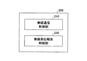
- FIG. 4 is a block diagram showing a functional configuration of a base station according to an embodiment of the present invention.
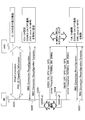
- FIG. 5 is a sequence diagram illustrating uplink carrier aggregation communication processing according to an embodiment of the present invention.
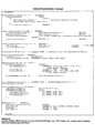
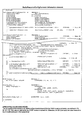
- FIG. 6 is a diagram illustrating a signaling data structure according to an embodiment of the present invention.
- FIG. 7 is a diagram illustrating a signaling data structure according to an embodiment of the present invention.
- FIG. 8 is a sequence diagram illustrating uplink carrier aggregation communication processing according to another embodiment of the present invention.
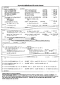
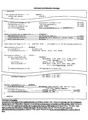
- FIG. 9 is a diagram illustrating a signaling data structure according to an embodiment of the present invention.
- FIG. 10 is a diagram illustrating a signaling data structure according to an embodiment of the present invention.
- FIG. 11 is a sequence diagram illustrating uplink carrier aggregation communication processing according to another embodiment of the present invention.
- FIG. 12 is a diagram illustrating a signaling data structure according to an embodiment of the present invention.
- FIG. 13 is a block diagram illustrating a functional configuration of a user apparatus according to another embodiment of the present invention.
- FIG. 14 is a diagram illustrating a signaling data structure according to another embodiment of the present invention.
- FIG. 15 is a diagram illustrating a signaling data structure according to another embodiment of the present invention.
- FIG. 16 is a block diagram showing a functional configuration of a user apparatus according to still another embodiment of the present invention.
- FIG. 17 is a diagram illustrating a signaling data structure according to still another embodiment of the present invention.
- a user apparatus and a base station having an uplink carrier aggregation function are disclosed.
- the base station sets a frequency band that causes interference with a positioning signal from a positioning system due to intermodulation distortion due to uplink carrier aggregation
- the base station sets a radio positioning function of the user apparatus. Set to report start or stop.
- the wireless positioning report function is set, the user apparatus reports the activation of the wireless positioning function to the base station when the wireless positioning function is activated.
- the base station controls wireless communication with the user apparatus so as to avoid occurrence of interference.
- the base station may reduce the transmission power to the user apparatus so as to avoid interference with the positioning signal while performing the wireless positioning at the time of setting up the uplink carrier aggregation. Thereby, it is possible to simultaneously perform uplink carrier aggregation communication and radio positioning.
- FIG. 2A is a schematic diagram illustrating a wireless communication system according to an embodiment of the present invention.
- the radio communication system 10 includes a user apparatus 100 and a base station 200.
- the radio communication system 10 supports uplink carrier aggregation, and the user apparatus 100 transmits radio signals to the base station 200 using a plurality of component carriers CC # 1 and CC # 2 at the same time as shown in the figure. Can do.
- the user apparatus 100 is only shown to perform uplink carrier aggregation communication with one base station 200, but the present invention is not limited to this.
- the user apparatus 100 may perform uplink transmission simultaneously with the plurality of base stations 200 by simultaneously using component carriers provided by the plurality of base stations 200.
- only one base station 200 is shown, but a number of base stations 200 are arranged to cover the service area of the wireless communication system 10.
- User apparatus 100 has an uplink carrier aggregation function for transmitting radio signals to base station 200 by simultaneously using a plurality of carriers provided by base station 200. Moreover, the user apparatus 100 has a communication function for performing wireless communication with other wireless communication systems such as the positioning system 300 (GNSS system).
- GNSS system positioning system 300
- the user apparatus 100 may be any appropriate information processing apparatus having a wireless communication function such as a smartphone, a mobile phone, a tablet, a mobile router, and a wearable terminal as illustrated.
- the user apparatus 100 transmits and receives radio signals to and from the base station 200, such as a CPU (Central Processing Unit) 101 such as a processor, a memory apparatus 102 such as a RAM (Random Access Memory) and flash memory, and the like.
- each function and process of the user device 100 described later may be realized by the CPU 101 processing or executing data or a program stored in the memory device 102.
- the user apparatus 100 is not limited to the hardware configuration described above, and may be configured by a circuit that realizes one or more of the processes described below.
- the base station 200 wirelessly connects to the user apparatus 100, thereby receiving, in the user apparatus 100, a downlink (DL) packet received from a network apparatus such as an upper station or a server that is communicatively connected to a core network (not shown). At the same time, the uplink (UL) packet received from the user apparatus 100 is transmitted to the network apparatus.
- the base station 200 has an uplink carrier aggregation function that simultaneously receives radio signals from the user apparatus 100 via a plurality of carriers.
- the base station 200 typically includes an antenna 201 for transmitting and receiving radio signals to and from the user apparatus 100, and a first communication interface (for communicating with an adjacent base station 200). 202, a second communication interface (S1 interface, etc.) 203 for communicating with the core network, a processor 204 and a circuit for processing transmission / reception signals with the user device 100, a hardware resource such as a memory device 205, etc. Composed.
- a hardware resource such as a memory device 205, etc. Composed.
- Each function and process of the base station 200 to be described later may be realized by the processor 204 processing or executing data or a program stored in the memory device 205.
- the base station 200 is not limited to the hardware configuration described above, and may have any other appropriate hardware configuration.
- the positioning system 300 transmits a positioning signal to the user device 100.
- the positioning system 300 is, for example, a GNSS system such as a GPS system, a Glonass system, a Galileo system, or a Beidou system, and transmits a positioning signal to the user apparatus 100 in each frequency band using a plurality of satellites.
- a GNSS system such as a GPS system, a Glonass system, a Galileo system, or a Beidou system
- a reception band of a radio signal from the positioning system 300 as a frequency band overlapping with a generation region of intermodulation distortion due to uplink carrier aggregation.
- the present invention is not limited to the positioning system 300, and may be applied to any other wireless communication system that uses a frequency band that receives interference due to uplink transmission from the user apparatus 100.
- FIG. 3 is a block diagram illustrating a functional configuration of a user apparatus according to an embodiment of the present invention.
- the user apparatus 100 includes a wireless communication control unit 110, a wireless positioning unit 120, and a wireless positioning state report unit 130.
- the wireless communication control unit 110 controls wireless communication with the base station 200. Specifically, the radio communication control unit 110 transmits / receives various radio channels such as an uplink / downlink control channel and an uplink / downlink data channel to / from the base station 200, and is provided by the base station 200. Uplink carrier aggregation is performed in which a plurality of carriers are simultaneously used to transmit radio signals to the base station 200.
- the wireless positioning unit 120 executes a wireless positioning function based on the wireless signal received from the positioning system 300.
- the wireless positioning function measures the position of the user device 100 based on the positioning signal received from the positioning system 300.
- the wireless positioning unit 120 receives the positioning signal transmitted from the positioning system 300 and specifies the position of the user device 100 based on the received positioning signal.
- the radio positioning unit 120 receives positioning signals transmitted from a plurality of satellites of the positioning system 300, and specifies the position of the user apparatus 100 based on a known positioning algorithm from the received plurality of positioning signals.
- the wireless positioning unit 120 is activated in response to an activation request from an application used by the user (for example, an application that provides location-related information such as a map application).
- the radio positioning status reporting unit 130 reports the activation or deactivation of the radio positioning function to the base station 200 when uplink carrier aggregation is set. Specifically, in response to the radio positioning unit 120 starting and / or stopping the radio positioning function while the uplink carrier aggregation is set in the user apparatus 100, the radio positioning state reporting unit 130 The base station 200 is notified that the wireless positioning function has been activated and / or stopped.
- the radio positioning status reporting unit 130 may be activated or deactivated by an instruction from the base station 200. Specifically, only when the base station 200 instructs the user apparatus 100 to report activation and / or suspension of the radio positioning function and receives the report instruction, the radio positioning status report unit 130 performs radio positioning. The activation and / or deactivation of the function may be reported to the base station 200. Thereby, the base station 200 activates and / or stops the radio positioning function only when a carrier that causes interference with the positioning signal from the positioning system 300 is set in the user apparatus 100 during the uplink carrier aggregation. Can be reported to the user device 100.
- the base station 200 may cause the user apparatus 100 to stop reporting on activation and / or termination of the radio positioning function.
- the base station 200 can control wireless communication with the user apparatus 100 so as to avoid interference. For example, the base station 200 schedules a resource block that does not cause interference with a positioning signal in uplink carrier aggregation to the user apparatus 100 while the radio positioning function is activated by the user apparatus 100, and the resource block causes the user apparatus 100 to Uplink data may be transmitted. Further, even when uplink carrier aggregation is set, the base station 200 causes the user apparatus 100 to transmit uplink data using only one carrier while the radio positioning function by the user apparatus 100 is activated. Alternatively, the uplink carrier aggregation setting may be deleted, or the secondary cell (SCell) may be deactivated.
- SCell secondary cell
- the radio communication control unit 110 when the base station 200 instructs the base station 200 to reduce the transmission power for the radio positioning function, the radio communication control unit 110 reduces the transmission power while the radio positioning function is activated, and the base station 200. Uplink carrier aggregation communication may be executed. In order to reduce interference with a positioning signal from the positioning system 300 due to intermodulation distortion that occurs during uplink carrier aggregation, the radio communication control unit 110 increases transmission power reduction instructed from the base station 200. You may apply to link communication. In the LTE standard, the base station 200 may indicate the maximum transmission power to be reduced by the user apparatus 100 when the radio positioning function is activated during uplink carrier aggregation setting by using an A-MPR (Additional Maximum Power Reduction) parameter. . At this time, when the wireless positioning function is activated during the setting of uplink carrier aggregation, the wireless communication control unit 110 reduces the maximum transmission power by the amount of power instructed by the A-MPR while the wireless positioning is being performed. .
- A-MPR Additional Maximum Power Reduction
- the radio positioning status reporting unit 130 may further report the positioning system 300, the reception center frequency of the positioning system 300, and the reception bandwidth of the positioning system 300 to the base station 200. That is, when the radio positioning unit 120 activates or stops the radio positioning function, the radio positioning state report unit 130 reports activation or deactivation of the radio positioning function, and receives the type and reception of the positioning system 300 used by the user device 100. The center frequency and reception bandwidth may be reported.
- the user apparatus 100 can use various positioning systems 300 such as GPS, and each positioning system 300 uses a unique frequency band, and each user apparatus 100 typically includes: Only a part of the frequency band of the positioning system 300 is used instead of the entire frequency band.
- the radio positioning status reporting unit 130 may report the type, the reception center frequency, and the reception bandwidth of the positioning system 300 being used to the base station 200 together with the activation or stop of the radio positioning function. Thereby, the base station 200 can know the details of the frequency band used by the user apparatus 100 for receiving positioning signals, and can appropriately control the radio communication with the user apparatus 100 to avoid interference. become.
- FIG. 4 is a block diagram showing a functional configuration of a base station according to an embodiment of the present invention.
- the base station 200 includes a radio communication control unit 210 and a radio positioning report control unit 220.
- the wireless communication control unit 210 controls wireless communication with the user device 100. Specifically, the radio communication control unit 210 transmits / receives various control signals and data signals to / from the user apparatus 100, and receives radio signals from the user apparatus 100 by a plurality of carriers while setting up uplink carrier aggregation. To do.
- the radio positioning report control unit 220 controls the radio positioning report function for the user apparatus 100 that reports activation or deactivation of the radio positioning function based on the radio signal received from the positioning system 300, and receives the radio positioning report from the positioning system 300 in uplink carrier aggregation.
- the user apparatus 100 is activated with a radio positioning report function. That is, as described above, the user apparatus 100 has a wireless positioning report function for reporting the start and / or stop of the wireless positioning function to the base station 200. The start and stop of the wireless positioning report function is performed by the wireless positioning report control. Controlled by the unit 220.
- the radio positioning report control unit 220 When the radio positioning report control unit 220 causes the user apparatus 100 to activate the radio positioning report function, the user apparatus 100 reports the activation and / or stop of the radio positioning function to the base station 200. On the other hand, when the radio positioning report control unit 220 causes the user apparatus 100 to stop the radio positioning report function, the user apparatus 100 stops reporting the activation and / or stop of the radio positioning function.
- the radio positioning report control unit 220 activates the radio positioning report function in the user apparatus 100, and the radio positioning report function When starting and / or stopping the wireless positioning function during activation, the user apparatus 100 is made to report the start and / or stop of the wireless positioning function.
- the wireless communication control unit 210 may control wireless communication with the user device 100 so as to avoid interference. Specifically, the radio communication control unit 210 schedules a resource block that does not cause interference with a positioning signal in the uplink carrier aggregation to the user apparatus 100 while the radio positioning function by the user apparatus 100 is activated, and the resource block Thus, the uplink data may be transmitted to the user apparatus 100. In addition, even when uplink carrier aggregation is set, the wireless communication control unit 210 transmits uplink data to the user apparatus 100 using only one carrier while the wireless positioning function is activated by the user apparatus 100. It may be transmitted, the uplink carrier aggregation setting may be deleted, or the secondary cell (SCell) may be deactivated.
- SCell secondary cell
- the wireless communication control unit 210 may notify the user apparatus 100 of transmission power that should be reduced during activation of the wireless positioning function.
- the radio communication control unit 210 transmits uplink data by using the A-MPR parameter when the radio positioning function during the uplink carrier aggregation setting is activated and the number of resource blocks specified by the standard is exceeded. In this case, the maximum transmission power to be reduced may be indicated.
- the user apparatus 100 transmits the uplink data with the number of resource blocks or more, and the maximum transmission power is the amount of power indicated by the A-MPR. Reduce.
- the radio positioning report control unit 220 transmits a radio positioning report function to the user apparatus 100. May be stopped. That is, when deleting the uplink carrier aggregation setting for the user apparatus 100, or when deleting the setting of the frequency band that causes interference, the wireless positioning report control is performed in order to stop unnecessary wireless positioning reports from the user apparatus 100.
- the unit 220 may cause the user apparatus 100 to stop the wireless positioning report function. That is, when the frequency band that causes interference with the positioning signal in the uplink carrier aggregation is not set in the user apparatus 100, the radio positioning report control unit 220 does not activate the radio positioning report function in the user apparatus 100. Thereby, when interference does not occur due to intermodulation distortion of uplink carrier aggregation, unnecessary radio positioning reports from the user apparatus 100 can be stopped.
- FIG. 5 is a sequence diagram illustrating uplink carrier aggregation communication processing according to an embodiment of the present invention.
- the uplink carrier aggregation communication process is described in relation to the LTE standard.
- the illustrated uplink carrier aggregation communication processing is based on a specific resource of the LTE standard, but the present invention is not limited to the release, and uses uplink carrier aggregation such as a subsequent release. It may apply to any other release.
- step S101 connection processing is executed between the user apparatus 100 and the base station 200, and user capability information indicating that the uplink carrier aggregation function is supported is transmitted to the base station 200. Be notified. Note that if the connection has already been established between the user apparatus 100 and the base station 200 and the base station 200 has already acquired the user capability information of the user apparatus 100, step S101 may be omitted.
- the base station 200 sets a frequency band that causes interference with a radio signal from the positioning system 300 in the uplink carrier aggregation in the user apparatus 100, and a radio positioning function based on the radio signal received from the positioning system 300.
- the user apparatus 100 is activated with a wireless positioning report function for reporting activation or deactivation of the user.
- the base station 200 sets the uplink carrier aggregation by transmitting RRC (Radio Resource Control) Connection Reconfiguration to the user apparatus 100, and the information shown in FIG.
- step S103 when the radio positioning function is activated (GNSS on), the user apparatus 100 reports the activation of the radio positioning function to the base station 200 and performs uplink transmission.
- the user apparatus 100 may further report the positioning system 300, the reception center frequency of the positioning system 300, and the reception bandwidth of the positioning system 300 to the base station 200.
- the base station 200 controls wireless communication with the user apparatus 100 so as to avoid interference as described above. For example, the base station 200 schedules a resource block that does not cause interference with a positioning signal in uplink carrier aggregation to the user apparatus 100 while the radio positioning function is activated by the user apparatus 100, and the resource block causes the user apparatus 100 to Uplink data may be transmitted. Further, even when uplink carrier aggregation is set, the base station 200 causes the user apparatus 100 to transmit uplink data using only one carrier while the radio positioning function by the user apparatus 100 is activated. Alternatively, the uplink carrier aggregation setting may be deleted, or the secondary cell (SCell) may be deactivated.
- SCell secondary cell
- step S104 when the radio positioning function is stopped (GNSS off), the user apparatus 100 reports the stop of the radio positioning function to the base station 200.
- the user apparatus 100 may further report the positioning system 300, the reception center frequency of the positioning system 300, and the reception bandwidth of the positioning system 300 to the base station 200.
- the base station 200 deletes the uplink carrier aggregation setting and causes the user apparatus 100 to stop the radio positioning report function.
- FIG. 8 is a sequence diagram illustrating uplink carrier aggregation communication processing according to another embodiment of the present invention.
- the uplink carrier aggregation communication processing relates to an embodiment in which transmission power is reduced when uplink data is transmitted with more than a certain number of resource blocks according to A-MPR during activation of a radio positioning function in uplink carrier aggregation. Will be described in connection with the LTE standard.
- the illustrated uplink carrier aggregation communication processing is based on a specific resource of the LTE standard, but the present invention is not limited to the release, and uses uplink carrier aggregation such as a subsequent release. It may apply to any other release.
- step S201 connection processing is executed between the user apparatus 100 and the base station 200, and user capability information indicating that the uplink carrier aggregation function is supported is transmitted to the base station 200. Be notified. Note that if the connection has already been established between the user apparatus 100 and the base station 200 and the base station 200 has already acquired the user capability information of the user apparatus 100, step S201 may be omitted.
- the base station 200 sets a frequency band that causes interference with a radio signal from the positioning system 300 in the uplink carrier aggregation in the user apparatus 100, and a radio positioning function based on the radio signal received from the positioning system 300.
- the user apparatus 100 is activated with a wireless positioning report function for reporting activation or deactivation of the user.
- the base station 200 transmits an RRC Connection Reconfiguration to the user apparatus 100, thereby setting up uplink carrier aggregation and reporting a start and / or stop of the radio positioning function.
- the base station 200 notifies the user apparatus 100 of an A-MPR for reducing transmission power during activation of the radio positioning function in uplink carrier aggregation.
- the base station 200 may notify the transmission power to be individually reduced to the primary cell and the secondary cell of uplink carrier aggregation.
- the base station 200 may notify the A-MPR for the primary cell (PCell) of uplink carrier aggregation by “additionalSpectrumEmissionPcell2-r12” of the information element shown in FIG.
- the base station 200 may notify the A-MPR for the primary cell (SCell) of uplink carrier aggregation by the “additional Spectrum Emission Scell2-r12” of the information element shown in FIG.
- step S203 when the radio positioning function is activated (GNSS on), the user apparatus 100 reports the activation of the radio positioning function to the base station 200 and increases the number of resource blocks according to the instruction from the base station 200.
- the transmission power is reduced and uplink transmission is performed.
- the user apparatus 100 may further report the positioning system 300, the reception center frequency of the positioning system 300, and the reception bandwidth of the positioning system 300 to the base station 200.
- the base station 200 controls wireless communication with the user apparatus 100 so as to avoid interference as described above. For example, the base station 200 schedules a resource block that does not cause interference with a positioning signal in uplink carrier aggregation to the user apparatus 100 while the radio positioning function is activated by the user apparatus 100, and the resource block causes the user apparatus 100 to Uplink data may be transmitted. Further, even when uplink carrier aggregation is set, the base station 200 causes the user apparatus 100 to transmit uplink data using only one carrier while the radio positioning function by the user apparatus 100 is activated. Alternatively, the uplink carrier aggregation setting may be deleted, or the secondary cell (SCell) may be deactivated.
- SCell secondary cell
- step S204 when the wireless positioning function is stopped (GNSS off), the user apparatus 100 reports the stop of the wireless positioning function to the base station 200.
- the user apparatus 100 may further report the positioning system 300, the reception center frequency of the positioning system 300, and the reception bandwidth of the positioning system 300 to the base station 200.
- the base station 200 deletes the uplink carrier aggregation setting and causes the user apparatus 100 to stop the radio positioning report function.
- the base station 200 notifies the user apparatus 100 of deletion of A-MPR for reducing transmission power during activation of the radio positioning function in uplink carrier aggregation.
- the uplink carrier aggregation communication process for avoiding the interference of the positioning signal due to the intermodulation distortion caused by the uplink carrier aggregation has been described.
- the present invention is not limited to interference with positioning signals, and can be applied to other wireless communication systems that receive interference due to intermodulation distortion caused by uplink carrier aggregation.
- FIG. 11 is a sequence diagram illustrating uplink carrier aggregation communication processing according to another embodiment of the present invention.
- the uplink carrier aggregation communication processing relates to an embodiment in which the base station 200 controls the autonomous operation by the user apparatus 100 for ensuring the activation of the radio positioning function during an emergency call, and will be described in relation to the LTE standard. Is done.
- the illustrated uplink carrier aggregation communication processing is based on a specific resource of the LTE standard, but the present invention is not limited to the release, and uses uplink carrier aggregation such as a subsequent release. It may apply to any other release.
- An emergency call location notification function that automatically obtains location information about the location of the call and notifies the destination of the location information when an emergency call is sent to the emergency response organization such as the police or fire department. is there.
- a control in which the base station 200 does not allocate resources in a plurality of uplink component carriers to the user apparatus 100 that has made an emergency call under the LTE standard is being studied (3GPP R4 -148117). If the base station 200 allocates resources to the user apparatus 100 that is in an emergency call in a plurality of uplink component carriers, the user apparatus 100 can autonomously stop the uplink transmission of the secondary cell. Yes.
- the base station 200 cannot quickly grasp the autonomous operation, and may allocate unnecessary uplink resources to the user apparatus 100. There is. For this reason, in the present embodiment, the base station 200 can control the autonomous operation by the user apparatus 100.
- step S301 connection processing is executed between the user apparatus 100 and the base station 200, and user capability information indicating that the uplink carrier aggregation function is supported is transmitted to the base station 200. Be notified.
- wireless communication control part 110 of the user apparatus 100 has the autonomous transmission cancellation function which cancels the uplink transmission of a secondary cell during an emergency call, when the uplink resource is allocated on the some component carrier.
- the autonomous transmission stop function can be activated by activation permission from the base station 200. Note that if the connection is already established between the user apparatus 100 and the base station 200 and the base station 200 has already acquired the user capability information of the user apparatus 100, step S301 may be omitted.
- the base station 200 sets a frequency band that causes interference with the radio signal from the positioning system 300 in the uplink carrier aggregation in the user apparatus 100, and the radio positioning function based on the radio signal received from the positioning system 300.
- the user apparatus 100 is activated with a wireless positioning report function for reporting activation or deactivation of the user.
- the base station 200 stops the uplink transmission of the secondary cell during the emergency call. Allows activation of the autonomous transmission stop function.
- step S303 the user device 100 sends an emergency call to an emergency response organization such as the police or fire department.
- an emergency response organization such as the police or fire department.
- step S304 the base station 200 allocates resources to the user equipment 100 on a plurality of uplink component carriers.
- autonomousDenialSCell setup
- the base station 200 can control the activation of the autonomous transmission stop function by the user device 100 during an emergency call, and the base station 200 can grasp the operation assumed by the user device 100 and It is possible to avoid assigning unnecessary uplink resources to the user apparatus 100 that has transmitted the call.
- the present invention is not limited to the positioning system 300, and may be applied to any other wireless communication system that uses a frequency band that receives interference due to uplink transmission from the user apparatus 100.
- a wireless communication system Wi-Fi, Bluetooth (registered trademark), etc.
- an unlicensed band such as 2.4 GHz or 5 GHz
- an interfered system 400 not shown
- FIG. 13 is a block diagram showing a functional configuration of a user apparatus according to another embodiment of the present invention.
- the user apparatus 100A includes a wireless communication control unit 110A and an interfered system information report unit 140A.
- the wireless communication control unit 110A controls wireless communication with the base station 200. Specifically, similarly to the radio communication control unit 110, the radio communication control unit 110A transmits and receives various radio channels such as an uplink / downlink control channel and an uplink / downlink data channel to and from the base station 200. In addition, uplink carrier aggregation is performed in which a plurality of carriers provided by the base station 200 are simultaneously used to transmit radio signals to the base station 200.
- the interfered system information reporting unit 140A reports the system information of the interfered system 400 that receives interference due to uplink carrier aggregation to the base station 200.
- the user apparatus 100A can wirelessly communicate with an interfered system 400 such as Wi-Fi or Bluetooth (registered trademark) that uses an unlicensed band that is interfered by uplink carrier aggregation. It is.
- the interfered system information reporting unit 140A determines whether to start and / or stop the wireless communication. Report to 200.
- the system information may include the center frequency of the interfered system 400 and the reception bandwidth.
- the user apparatus 100A can use various interfered systems 400 such as Wi-Fi and Bluetooth (registered trademark), and the interfered system information report unit 140A bases the center frequency and the reception bandwidth on the interfered system 400. Notify the station 200.
- the base station 200 uses a band (such as an unlicensed band) used for wireless communication between the user apparatus 100A and the interfered system 400. It is possible to know details and to more appropriately control wireless communication with the user apparatus 100A so as to avoid interference.
- the interfered system information reporting unit 140A uses the signaling data structure as shown in FIG.
- the interfered system information report unit 140A may report the system information of each of the multiple interfered systems 400 to the base station 200.
- the interfered system information reporting unit 140A may be activated or deactivated by an instruction from the base station 200. Specifically, only when the base station 200 instructs the user apparatus 100A to report the start and / or stop of wireless communication with the interfered system 400 and receives the report instruction, the interfered system information The reporting unit 140A may report the start and / or stop of wireless communication with the interfered system 400 to the base station 200. Thus, the base station 200 performs wireless communication with the interfered system 400 only when the carrier that causes interference in wireless communication with the interfered system 400 is set in the user apparatus 100A during uplink carrier aggregation. It is possible to cause the user device 100A to report the start and / or stop of the user.
- the base station 200 performs wireless communication with the interfered system 400. Unnecessary reporting of start and / or stop can be avoided.
- the base station 200 bases the in-device coexistence notification “InDeviceCoexIndication” including the system information “VictimSystemInfo” of the interfered system 400.
- the user apparatus 100A may be instructed to transmit to the station 200.
- the interfered system information reporting unit 140A In response to the uplink carrier aggregation being set, the interfered system information reporting unit 140A An in-device coexistence notification “InDeviceCoexIndication” including the system information “VictimSystemInfo” of the system 400 may be transmitted to the base station 200. Moreover, when deleting the setting of the uplink carrier aggregation with respect to the user apparatus 100A, the base station 200 may stop the user apparatus 100A from reporting start and / or stop of wireless communication with the interfered system 400.
- the base station 200 can control the wireless communication with the user apparatus 100A so as to avoid the interference. For example, the base station 200 schedules resource blocks that do not cause interference with the interfered system 400 in the uplink carrier aggregation to the user apparatus 100A during activation of wireless communication with the interfered system 400 by the user apparatus 100A, and The uplink data may be transmitted to the user apparatus 100A using the resource block. In addition, even when uplink carrier aggregation is set, the base station 200 is up to the user apparatus 100A using only one carrier while the user apparatus 100A is starting wireless communication with the interfered system 400. Link data may be transmitted, the uplink carrier aggregation setting may be deleted, or the secondary cell (SCell) may be deactivated.
- SCell secondary cell
- the wireless communication control unit 110A when the base station 200 instructs to reduce transmission power for wireless communication with the interfered system 400, the wireless communication control unit 110A performs the communication during activation of wireless communication with the interfered system 400. Transmission power may be reduced and uplink carrier aggregation communication with the base station 200 may be executed. In order to reduce interference with the interfered system 400 due to intermodulation distortion occurring during the execution of uplink carrier aggregation, the radio communication control unit 110A reduces the transmission power instructed by the base station 200 to uplink communication. You may apply. In the LTE standard, the base station 200 may instruct the maximum transmission power that the user apparatus 100A should reduce when starting wireless communication with the interfered system 400 during the uplink carrier aggregation setting by the A-MPR parameter. At this time, when wireless communication with the interfered system 400 is activated during the setting of uplink carrier aggregation, the wireless communication control unit 110A maximizes the amount of power indicated by the A-MPR during execution of the wireless communication. Reduce transmission power.
- uplink interference is not limited to inter-modulation distortion (IMD) caused by uplink carrier aggregation as described above, but is also caused by other causes such as harmonic components of single carrier uplink transmission. sell. For this reason, by notifying the base station 200 of the cause of interference, the base station 200 can appropriately cope with uplink interference.
- IMD inter-modulation distortion
- FIG. 16 is a block diagram showing a functional configuration of a user apparatus according to still another embodiment of the present invention.
- the user apparatus 100B includes a wireless communication control unit 110B and an interference cause notification unit 120B.
- the wireless communication control unit 110B controls wireless communication with the base station 200. Specifically, similarly to the wireless communication control units 110 and 110A, the wireless communication control unit 110B performs various wireless channels such as an uplink / downlink control channel and an uplink / downlink data channel with the base station 200. In addition, uplink carrier aggregation is performed in which a plurality of carriers provided by the base station 200 are simultaneously used to transmit radio signals to the base station 200. Further, the radio communication control unit 110B supports uplink transmission by a single carrier method. In single carrier uplink transmission, it is known that harmonic components cause interference.
- the interference cause notification unit 120B notifies the base station 200 of the cause of the uplink interference.
- the cause of uplink interference may be intermodulation distortion caused by uplink carrier aggregation or a harmonic of single carrier uplink transmission.
- the interference cause notifying unit 120B determines that the intermodulation distortion (IMD) caused by uplink carrier aggregation is the cause of interference.
- IMD intermodulation distortion
- the interference cause notifying unit 120B notifies the base station 200 that the harmonic component of the single carrier uplink transmission is the cause of the interference.
- the interference cause notification unit 120B may notify the cause of interference in the information element “interferenceCauseUL” of the in-device coexistence notification “InDeviceCoexIndication”. For example, when the cause of interference is intermodulation distortion caused by uplink carrier aggregation, the interference cause notification unit 120B sets the value of “interferenceCauseUL” to “imd” and notifies the base station 200 of “InDeviceCoexIndication”. Good. Further, when the cause of interference is a harmonic component of single carrier uplink transmission, the interference cause notification unit 120B sets the value of “interferenceCauseUL” to “harmonics” and notifies the base station 200 of “InDeviceCoexIndication”. Good.
- the cause of uplink interference is not limited to these, and any other cause may be notified to base station 200.
- the present application includes Japanese Patent Application No. 2014-227473 filed on November 7, 2014, Japanese Patent Application No. 2015-014550 filed on January 28, 2015, and Japanese Patent Application filed on May 14, 2015. This is claimed based on the benefit of priority of Japanese Patent Application No. 2015-098863 and Japanese Patent Application No. 2015-160090 filed on Aug. 14, 2015. No. 2014-227473, No. 2015-014550 , 2015-098863 and 2015-160090 are hereby incorporated by reference.
Landscapes
- Engineering & Computer Science (AREA)
- Computer Networks & Wireless Communication (AREA)
- Signal Processing (AREA)
- Radar, Positioning & Navigation (AREA)
- Remote Sensing (AREA)
- Physics & Mathematics (AREA)
- General Physics & Mathematics (AREA)
- Business, Economics & Management (AREA)
- Health & Medical Sciences (AREA)
- Emergency Management (AREA)
- Environmental & Geological Engineering (AREA)
- Public Health (AREA)
- Mobile Radio Communication Systems (AREA)
Abstract
Description
100、100A、100B ユーザ装置
200 基地局
300 測位システム
400 被干渉システム
Claims (15)
- アップリンクキャリアアグリゲーション機能を有するユーザ装置であって、
基地局との無線通信を制御する無線通信制御部と、
測位システムから受信した無線信号に基づく無線測位機能を実行する無線測位部と、
アップリンクキャリアアグリゲーションが設定されているとき、前記無線測位機能の起動又は停止を基地局に報告する無線測位状態報告部と、
を有するユーザ装置。 - 前記無線測位状態報告部は、前記基地局からの指示によって起動又は停止される、請求項1記載のユーザ装置。
- 前記無線測位状態報告部は更に、前記測位システム、前記測位システムの受信中心周波数及び前記測位システムの受信帯域幅を前記基地局に報告する、請求項1又は2記載のユーザ装置。
- 前記無線測位機能のための送信電力の低減を前記基地局から指示されると、前記無線通信制御部は、前記無線測位機能の起動中に前記送信電力を低減して、前記基地局とのアップリンクキャリアアグリゲーション通信を実行する、請求項1乃至3何れか一項記載のユーザ装置。
- 前記無線通信制御部は、複数のコンポーネントキャリア上でアップリンクリソースが割り当てられている場合、緊急呼中にセカンダリセルのアップリンク送信を中止する自律送信中止機能を有し、
前記無線通信制御部は、前記基地局からの起動許可によって前記自律送信中止機能を起動する、請求項1乃至4何れか一項記載のユーザ装置。 - アップリンクキャリアアグリゲーション機能を有する基地局であって、
ユーザ装置との無線通信を制御する無線通信制御部と、
測位システムから受信した無線信号に基づく無線測位機能の起動又は停止を報告する前記ユーザ装置に対する無線測位報告機能を制御する無線測位報告制御部と、
アップリンクキャリアアグリゲーションにおいて前記測位システムからの無線信号と干渉を生じさせる周波数帯域を前記ユーザ装置に設定しているとき、前記無線測位報告制御部は、前記ユーザ装置に前記無線測位報告機能を起動させる基地局。 - 前記ユーザ装置に対するアップリンクキャリアアグリゲーションの設定を削除するとき、又は前記干渉を生じさせる周波数帯の設定を削除するとき、前記無線測位報告制御部は、前記ユーザ装置に前記無線測位報告機能を停止させる、請求項6記載の基地局。
- 前記ユーザ装置から前記無線測位機能の起動の報告を受信すると、前記無線通信制御部は、前記干渉を回避するよう前記ユーザ装置との無線通信を制御する、請求項6又は7記載の基地局。
- 前記無線通信制御部は、前記無線測位機能の起動中にあるリソースブロック数以上でアップリンクデータを送信する場合に低減すべき送信電力を前記ユーザ装置に通知する、請求項6乃至8何れか一項記載の基地局。
- 前記無線測位報告制御部は、複数のコンポーネントキャリア上でアップリンクリソースが割り当てられている場合、前記ユーザ装置が緊急呼中にセカンダリセルのアップリンク送信を中止する自律送信中止機能の起動を許可する、請求項6乃至9何れか一項記載の基地局。
- ユーザ装置と基地局との間のアップリンクキャリアアグリゲーション通信方法であって、
前記基地局が、アップリンクキャリアアグリゲーションにおいて測位システムからの無線信号と干渉を生じさせる周波数帯域を前記ユーザ装置に設定するステップと、
前記基地局が、前記測位システムから受信した無線信号に基づく無線測位機能の起動又は停止を報告する無線測位報告機能を前記ユーザ装置に起動させるステップと、
前記ユーザ装置が、前記無線測位機能の起動を前記基地局に報告するステップと、
前記基地局が、前記干渉を回避するよう前記ユーザ装置との無線通信を制御するステップと、
を有するアップリンクキャリアアグリゲーション通信方法。 - アップリンクキャリアアグリゲーション機能を有するユーザ装置であって、
基地局との無線通信を制御する無線通信制御部と、
アップリンクキャリアアグリゲーションにより干渉を受ける被干渉システムのシステム情報を前記基地局に報告する被干渉システム情報報告部と、
を有するユーザ装置。 - 前記システム情報は、前記被干渉システムの中心周波数及び受信帯域幅を含む、請求項12記載のユーザ装置。
- アップリンクキャリアアグリゲーション機能を有するユーザ装置であって、
基地局との無線通信を制御する無線通信制御部と、
アップリンク干渉の原因を前記基地局に通知する干渉原因通知部と、
を有するユーザ装置。 - 前記アップリンク干渉の原因は、アップリンクキャリアアグリゲーションにより生じる相互変調歪み、又はシングルキャリアアップリンク送信の高調波である、請求項14記載のユーザ装置。
Priority Applications (5)
| Application Number | Priority Date | Filing Date | Title |
|---|---|---|---|
| CN201580006273.XA CN105940696A (zh) | 2014-11-07 | 2015-11-05 | 用户装置、基站以及上行链路载波聚合通信方法 |
| JP2016534742A JPWO2016072443A1 (ja) | 2014-11-07 | 2015-11-05 | ユーザ装置、基地局及びアップリンクキャリアアグリゲーション通信方法 |
| US15/114,425 US10757594B2 (en) | 2014-11-07 | 2015-11-05 | User equipment, base station and uplink carrier aggregation communication method |
| EP15857607.4A EP3217702A4 (en) | 2014-11-07 | 2015-11-05 | User device, base station, and uplink carrier aggregation communication method |
| EP20192626.8A EP3761693A1 (en) | 2014-11-07 | 2015-11-05 | User equipment, base station and uplink carrier aggregation communication method |
Applications Claiming Priority (8)
| Application Number | Priority Date | Filing Date | Title |
|---|---|---|---|
| JP2014227473 | 2014-11-07 | ||
| JP2014-227473 | 2014-11-07 | ||
| JP2015-014550 | 2015-01-28 | ||
| JP2015014550 | 2015-01-28 | ||
| JP2015098863 | 2015-05-14 | ||
| JP2015-098863 | 2015-05-14 | ||
| JP2015-160090 | 2015-08-14 | ||
| JP2015160090 | 2015-08-14 |
Publications (1)
| Publication Number | Publication Date |
|---|---|
| WO2016072443A1 true WO2016072443A1 (ja) | 2016-05-12 |
Family
ID=55909167
Family Applications (1)
| Application Number | Title | Priority Date | Filing Date |
|---|---|---|---|
| PCT/JP2015/081128 Ceased WO2016072443A1 (ja) | 2014-11-07 | 2015-11-05 | ユーザ装置、基地局及びアップリンクキャリアアグリゲーション通信方法 |
Country Status (5)
| Country | Link |
|---|---|
| US (1) | US10757594B2 (ja) |
| EP (2) | EP3217702A4 (ja) |
| JP (1) | JPWO2016072443A1 (ja) |
| CN (1) | CN105940696A (ja) |
| WO (1) | WO2016072443A1 (ja) |
Cited By (1)
| Publication number | Priority date | Publication date | Assignee | Title |
|---|---|---|---|---|
| JPWO2019065634A1 (ja) * | 2017-09-27 | 2020-08-06 | 株式会社Nttドコモ | ユーザ装置及び干渉制御方法 |
Families Citing this family (15)
| Publication number | Priority date | Publication date | Assignee | Title |
|---|---|---|---|---|
| WO2017030480A1 (en) * | 2015-08-14 | 2017-02-23 | Telefonaktiebolaget Lm Ericsson (Publ) | Signaling of idc problems |
| US10772113B2 (en) * | 2017-02-06 | 2020-09-08 | Qualcomm Incorporated | Autonomous uplink transmission techniques using shared radio frequency spectrum |
| CN106851729B (zh) * | 2017-02-27 | 2019-06-14 | 中国联合网络通信集团有限公司 | 一种载波最大发送功率的分配方法及装置 |
| DE102017106858A1 (de) * | 2017-03-30 | 2018-10-04 | Intel Corporation | Verbesserungen für den Aufbau von Notrufen |
| WO2019023857A1 (en) * | 2017-07-31 | 2019-02-07 | Zte Corporation | METHODS AND COMPUTER DEVICE FOR PERFORMING WIRELESS DEVICE DEVICE COMMUNICATION USING AGGREGATION OF LATERAL BINDING CARRIERS |
| EP3462622B1 (en) | 2017-09-11 | 2021-11-24 | Apple Inc. | Detection of intermodulation issues and transmission scheme configuration to remedy intermodulation issues |
| WO2019047217A1 (en) * | 2017-09-11 | 2019-03-14 | Apple Inc. | DETECTION OF INTERMODULATION PROBLEMS AND CONFIGURATION OF TRANSMISSION METHOD FOR ADDRESSING INTERMODULATION PROBLEMS |
| DE102017222356A1 (de) * | 2017-12-11 | 2019-06-13 | Robert Bosch Gmbh | Verfahren zum Betreiben eines GNSS-Sensors eines Fahrzeugs |
| CN109996351B (zh) * | 2017-12-29 | 2020-11-17 | 维沃移动通信有限公司 | 一种配置信息的传输方法和相关设备 |
| US11496264B2 (en) * | 2019-02-15 | 2022-11-08 | Qualcomm Incorporated | Interaction of positioning and media access control procedures |
| CN110505684A (zh) * | 2019-07-22 | 2019-11-26 | 维沃移动通信有限公司 | 定位方法及移动终端 |
| JP7677986B2 (ja) * | 2020-02-19 | 2025-05-15 | クゥアルコム・インコーポレイテッド | 衝突する測位状態情報(psi)報告についての優先度および衝突ルールのための方法および装置 |
| PH12022551660A1 (en) | 2020-02-21 | 2024-01-29 | Qualcomm Inc | Positioning reference signal processing |
| US11985597B2 (en) * | 2021-08-05 | 2024-05-14 | Qualcomm Incorporated | Techniques for aperiodic discontinuous reception mode communications |
| US12041000B2 (en) | 2021-08-05 | 2024-07-16 | Qualcomm Incorporated | Techniques for communicating data channel transmissions |
Citations (5)
| Publication number | Priority date | Publication date | Assignee | Title |
|---|---|---|---|---|
| WO2014020172A1 (en) * | 2012-08-03 | 2014-02-06 | Panasonic Corporation | Power headroom reporting for in-device coexistence interference avoidance |
| JP2014505422A (ja) * | 2011-01-07 | 2014-02-27 | パンテック カンパニー リミテッド | 無線通信システムにおける機器内共存干渉を調整する装置及び方法 |
| WO2014044436A1 (en) * | 2012-09-18 | 2014-03-27 | Panasonic Corporation | Maximization of scheduling opportunities in in-device coexistence interference scenarios |
| WO2014047894A1 (en) * | 2012-09-28 | 2014-04-03 | Broadcom Corporation | Mechanism for controlling multi-band communication |
| WO2014067131A1 (en) * | 2012-11-02 | 2014-05-08 | Broadcom Corporation | Signaling notification scheme for in-device coexistence interference |
Family Cites Families (12)
| Publication number | Priority date | Publication date | Assignee | Title |
|---|---|---|---|---|
| US8583159B2 (en) | 2009-10-08 | 2013-11-12 | Qualcomm Incorporated | Methods and apparatus for scaling transmit power of signals in wireless communications |
| US8750926B2 (en) * | 2010-06-18 | 2014-06-10 | Mediatek Inc. | System and method for coordinating multiple radio transceivers within the same device platform |
| US8838046B2 (en) * | 2010-06-18 | 2014-09-16 | Mediatek Inc. | System and method of hybrid FDM/TDM coexistence interference avoidance |
| US8879999B2 (en) | 2011-09-14 | 2014-11-04 | Marvell World Trade Ltd. | Using frequency bands characterized by type of unwanted interference for coexistence among multiple wireless communication technologies |
| KR101868865B1 (ko) * | 2012-03-19 | 2018-06-19 | 주식회사 골드피크이노베이션즈 | 무선통신 시스템에서 기기 내 공존 간섭을 제어하는 장치 및 방법 |
| EP2663113A1 (en) * | 2012-05-08 | 2013-11-13 | Panasonic Corporation | Improved coexistence interference reporting mechanism |
| CN103391180A (zh) * | 2012-05-10 | 2013-11-13 | 中国移动通信集团公司 | 一种终端内不同通信模块间共存的方法和装置 |
| US9497644B2 (en) | 2012-10-01 | 2016-11-15 | Telefonaktiebolaget Lm Ericsson (Publ) | User equipment, network node and methods therein |
| JP2014227473A (ja) | 2013-05-23 | 2014-12-08 | 東レ株式会社 | 複合材料用エポキシ樹脂組成物、繊維強化複合材料およびそれらの製造方法 |
| JP2015014550A (ja) | 2013-07-08 | 2015-01-22 | 積水化学工業株式会社 | 圧電センサシート原反及び圧電素子 |
| JP2015098863A (ja) | 2013-11-20 | 2015-05-28 | 株式会社東芝 | ディーゼル発電設備のオイルミスト管配管構造及びオイルミスト排出方法 |
| JP2015160090A (ja) | 2014-02-28 | 2015-09-07 | ブラザー工業株式会社 | 生体情報検出装置 |
-
2015
- 2015-11-05 EP EP15857607.4A patent/EP3217702A4/en not_active Withdrawn
- 2015-11-05 US US15/114,425 patent/US10757594B2/en active Active
- 2015-11-05 WO PCT/JP2015/081128 patent/WO2016072443A1/ja not_active Ceased
- 2015-11-05 JP JP2016534742A patent/JPWO2016072443A1/ja active Pending
- 2015-11-05 CN CN201580006273.XA patent/CN105940696A/zh active Pending
- 2015-11-05 EP EP20192626.8A patent/EP3761693A1/en not_active Withdrawn
Patent Citations (5)
| Publication number | Priority date | Publication date | Assignee | Title |
|---|---|---|---|---|
| JP2014505422A (ja) * | 2011-01-07 | 2014-02-27 | パンテック カンパニー リミテッド | 無線通信システムにおける機器内共存干渉を調整する装置及び方法 |
| WO2014020172A1 (en) * | 2012-08-03 | 2014-02-06 | Panasonic Corporation | Power headroom reporting for in-device coexistence interference avoidance |
| WO2014044436A1 (en) * | 2012-09-18 | 2014-03-27 | Panasonic Corporation | Maximization of scheduling opportunities in in-device coexistence interference scenarios |
| WO2014047894A1 (en) * | 2012-09-28 | 2014-04-03 | Broadcom Corporation | Mechanism for controlling multi-band communication |
| WO2014067131A1 (en) * | 2012-11-02 | 2014-05-08 | Broadcom Corporation | Signaling notification scheme for in-device coexistence interference |
Non-Patent Citations (3)
| Title |
|---|
| NTT DOCOMO, INC.: "LS on 2UL inter-band CA protection of GNSS", 3GPP TSG-RAN WG4 MEETING #73 R4-148117, 25 November 2014 (2014-11-25), XP050921457, Retrieved from the Internet <URL:http://www.3gpp.org/ftp/tsg_ran/WG4_Radio/TSGR4_73/Docs/R4-148117.zip> [retrieved on 20151225] * |
| NTT DOCOMO, INC.: "WF on 2UL inter-band CA protection of GNSS", 3GPP TSG-RAN WG4 MEETING #73 R4-147274, XP050879368, Retrieved from the Internet <URL:http://www.3gpp.org/ftp/tsg_ran/WG4_Radio/TSGR4_73/Docs/R4-147274.zip> [retrieved on 20151225] * |
| See also references of EP3217702A4 * |
Cited By (1)
| Publication number | Priority date | Publication date | Assignee | Title |
|---|---|---|---|---|
| JPWO2019065634A1 (ja) * | 2017-09-27 | 2020-08-06 | 株式会社Nttドコモ | ユーザ装置及び干渉制御方法 |
Also Published As
| Publication number | Publication date |
|---|---|
| US10757594B2 (en) | 2020-08-25 |
| EP3217702A4 (en) | 2017-11-01 |
| EP3761693A1 (en) | 2021-01-06 |
| US20160345193A1 (en) | 2016-11-24 |
| CN105940696A (zh) | 2016-09-14 |
| JPWO2016072443A1 (ja) | 2017-04-27 |
| EP3217702A1 (en) | 2017-09-13 |
Similar Documents
| Publication | Publication Date | Title |
|---|---|---|
| JPWO2016072443A1 (ja) | ユーザ装置、基地局及びアップリンクキャリアアグリゲーション通信方法 | |
| US10492233B2 (en) | System and method for switching frequencies in a wireless access solution based on dynamic spectrum allocation | |
| EP2494809B1 (en) | Method and system of tdm in-device coexistence interference avoidance | |
| US11116021B2 (en) | Communication apparatus and terminal apparatus | |
| JP7349363B2 (ja) | ユーザ装置及び干渉制御方法 | |
| JP6410927B2 (ja) | 通信システム、ネットワークノード、通信デバイス、方法及びコンピュータプログラム | |
| US9071976B2 (en) | Communication network device, communication device, method for managing communication resource allocation and method for communication resource allocation | |
| WO2017024659A1 (zh) | 无线通信系统中的电子设备和无线通信方法 | |
| CN116828553A (zh) | 一种通信方法及装置 | |
| JP7409533B2 (ja) | 通信制御装置、通信制御方法およびコンピュータプログラム | |
| JP7842178B2 (ja) | パス切替の方法、端末及びネットワーク側機器 | |
| CN112218368A (zh) | 一种通信方法及装置 | |
| WO2011086229A1 (en) | Systems, methods, and apparatuses for modem coordination | |
| US20250374095A1 (en) | Communication methods and communication apparatuses | |
| JP2019110352A (ja) | ユーザ装置 | |
| EP4233473B1 (en) | Data arrival indication | |
| CN121080114A (zh) | 用于ue到ue中继的层2中的直接端到端pc5链路支持的方法和信令过程 | |
| JP6442235B2 (ja) | ユーザ装置及び基地局 | |
| WO2024092606A1 (zh) | 无线通信的方法、终端设备和网络设备 | |
| WO2016080260A1 (ja) | 通信システム | |
| HK1229128B (zh) | 通信系统、网络节点、通信设备、方法和计算机程序 | |
| HK1229128A1 (en) | Communication system, network node, communication device, methods and computer programs |
Legal Events
| Date | Code | Title | Description |
|---|---|---|---|
| ENP | Entry into the national phase |
Ref document number: 2016534742 Country of ref document: JP Kind code of ref document: A |
|
| REEP | Request for entry into the european phase |
Ref document number: 2015857607 Country of ref document: EP |
|
| WWE | Wipo information: entry into national phase |
Ref document number: 2015857607 Country of ref document: EP |
|
| 121 | Ep: the epo has been informed by wipo that ep was designated in this application |
Ref document number: 15857607 Country of ref document: EP Kind code of ref document: A1 |
|
| WWE | Wipo information: entry into national phase |
Ref document number: 15114425 Country of ref document: US |
|
| NENP | Non-entry into the national phase |
Ref country code: DE |