WO2016072460A1 - 細胞培養システムおよび細胞培養容器 - Google Patents
細胞培養システムおよび細胞培養容器 Download PDFInfo
- Publication number
- WO2016072460A1 WO2016072460A1 PCT/JP2015/081200 JP2015081200W WO2016072460A1 WO 2016072460 A1 WO2016072460 A1 WO 2016072460A1 JP 2015081200 W JP2015081200 W JP 2015081200W WO 2016072460 A1 WO2016072460 A1 WO 2016072460A1
- Authority
- WO
- WIPO (PCT)
- Prior art keywords
- medium
- cell culture
- culture container
- supply
- temporary holding
- Prior art date
- Legal status (The legal status is an assumption and is not a legal conclusion. Google has not performed a legal analysis and makes no representation as to the accuracy of the status listed.)
- Ceased
Links
- 0 *=*1CCCC1 Chemical compound *=*1CCCC1 0.000 description 1
- OHDLZTDSTWANIC-UHFFFAOYSA-N C[I]1CCCC1 Chemical compound C[I]1CCCC1 OHDLZTDSTWANIC-UHFFFAOYSA-N 0.000 description 1
Images


Classifications
-
- C—CHEMISTRY; METALLURGY
- C12—BIOCHEMISTRY; BEER; SPIRITS; WINE; VINEGAR; MICROBIOLOGY; ENZYMOLOGY; MUTATION OR GENETIC ENGINEERING
- C12M—APPARATUS FOR ENZYMOLOGY OR MICROBIOLOGY; APPARATUS FOR CULTURING MICROORGANISMS FOR PRODUCING BIOMASS, FOR GROWING CELLS OR FOR OBTAINING FERMENTATION OR METABOLIC PRODUCTS, i.e. BIOREACTORS OR FERMENTERS
- C12M41/00—Means for regulation, monitoring, measurement or control, e.g. flow regulation
- C12M41/44—Means for regulation, monitoring, measurement or control, e.g. flow regulation of volume or liquid level
-
- C—CHEMISTRY; METALLURGY
- C12—BIOCHEMISTRY; BEER; SPIRITS; WINE; VINEGAR; MICROBIOLOGY; ENZYMOLOGY; MUTATION OR GENETIC ENGINEERING
- C12M—APPARATUS FOR ENZYMOLOGY OR MICROBIOLOGY; APPARATUS FOR CULTURING MICROORGANISMS FOR PRODUCING BIOMASS, FOR GROWING CELLS OR FOR OBTAINING FERMENTATION OR METABOLIC PRODUCTS, i.e. BIOREACTORS OR FERMENTERS
- C12M23/00—Constructional details, e.g. recesses, hinges
- C12M23/40—Manifolds; Distribution pieces
-
- C—CHEMISTRY; METALLURGY
- C12—BIOCHEMISTRY; BEER; SPIRITS; WINE; VINEGAR; MICROBIOLOGY; ENZYMOLOGY; MUTATION OR GENETIC ENGINEERING
- C12M—APPARATUS FOR ENZYMOLOGY OR MICROBIOLOGY; APPARATUS FOR CULTURING MICROORGANISMS FOR PRODUCING BIOMASS, FOR GROWING CELLS OR FOR OBTAINING FERMENTATION OR METABOLIC PRODUCTS, i.e. BIOREACTORS OR FERMENTERS
- C12M23/00—Constructional details, e.g. recesses, hinges
- C12M23/34—Internal compartments or partitions
-
- C—CHEMISTRY; METALLURGY
- C12—BIOCHEMISTRY; BEER; SPIRITS; WINE; VINEGAR; MICROBIOLOGY; ENZYMOLOGY; MUTATION OR GENETIC ENGINEERING
- C12M—APPARATUS FOR ENZYMOLOGY OR MICROBIOLOGY; APPARATUS FOR CULTURING MICROORGANISMS FOR PRODUCING BIOMASS, FOR GROWING CELLS OR FOR OBTAINING FERMENTATION OR METABOLIC PRODUCTS, i.e. BIOREACTORS OR FERMENTERS
- C12M29/00—Means for introduction, extraction or recirculation of materials, e.g. pumps
- C12M29/10—Perfusion
Definitions
- the present invention relates to a cell culture system and a cell culture container that can automatically replace the medium in the cell culture container.
- the present invention has been made in view of the above-described circumstances, and it is possible to easily and automatically replace the medium in the cell culture container in the cell culture space, and to make a system trouble by making the system simple.
- a cell culture system and a cell culture container that can reduce the risk of the occurrence of the above.
- One aspect of the present invention is a medium storage means for holding a medium for culturing cells, a holding space connected to the medium storage means and temporarily holding the medium supplied from the medium storage means, A temporary holding means having a discharge port for discharging the medium, a medium supply means connected to the discharge port of the temporary holding means and supplying the medium discharged from the temporary holding means to a cell culture container, and the cells
- the supply means is a cell culture system provided with a flow path capable of intermittently supplying a medium from the temporary holding means to the cell culture container according to the principle of siphon.
- a solution such as a medium can be intermittently supplied to the cell culture container with a simple configuration.
- Another aspect of the present invention is a medium storage means for holding a medium for culturing cells, a holding space connected to the medium storage means and temporarily holding the medium supplied from the medium storage means, A temporary holding means having a discharge port for discharging the medium; a medium supply means connected to the discharge port of the temporary holding means and supplying the medium discharged from the temporary holding means to the cell culture container; A medium discharge means for discharging a medium from the cell culture container, wherein the cell culture container is connected to the medium supply means at a position lower than the medium supply means in the direction of gravity,
- the culture medium supply means is a cell culture system including a supply gate that opens a flow path when the culture medium in the holding space reaches a predetermined amount.
- the temporary holding means employs a gate that opens and closes according to the amount of the medium in the medium, so that a solution such as a medium can be intermittently supplied to the cell culture container with a simple configuration.
- the medium supply unit is configured so that the medium before being supplied to the cell culture container is positioned above the discharge port of the temporary holding unit in the direction of gravity and has a maximum height in the direction of gravity of the holding space. You may provide the flow path which lets a lower position pass.
- the discharge port is disposed on a side surface of the temporary holding unit at a predetermined height from the bottom surface of the temporary holding unit, and the medium supply unit is disposed outside the temporary holding unit from the discharge port.
- a flow path may be formed.
- the medium supply means forms a flow path from the discharge port of the temporary holding means to the inside of the temporary holding means, and is connected to the discharge port of the temporary holding means.
- the opposite end may have an opening in the vicinity of a gap from the bottom surface of the temporary holding means.
- the supply gate opens the flow path when the medium in the holding space reaches a predetermined weight or when the upper surface of the medium in the holding space reaches a predetermined height. May be.
- the cell culture container may include a discharge port for discharging the medium to the outside when the height of the inner medium upper surface reaches a predetermined height. This makes it possible to automatically supply and discharge a solution such as a medium to and from the cell culture container with a simple configuration.
- a supply speed adjusting means for controlling a supply speed of the medium supplied from the medium storage means to the temporary holding means may be provided. This makes it possible to arbitrarily set the cycle for intermittently supplying the medium to the cell culture container.
- Another aspect of the present invention is a cell culture container including a supply port for supplying a culture medium, a discharge port for discharging the culture medium, and a tubular member connected to the discharge port, the tubular member Is a cell culture container that forms a flow path capable of intermittently discharging the medium in the cell culture container according to the principle of siphon.
- the tubular member may form a flow path that passes through a position above the discharge port in the direction of gravity and lower than the maximum height in the direction of gravity of the space in the cell culture vessel.
- the said discharge port is arrange
- the said tubular member is the said cell culture container from the said discharge port.
- a channel may be formed outside.
- the tubular member forms a flow path from the outlet to the inside of the cell culture container, and an end opposite to an end connected to the outlet of the tubular member is the cell culture.
- You may have an opening part in the vicinity which opened the gap
- Another aspect of the present invention is a cell culture system comprising the cell culture container described above and a medium supply means for supplying a medium from the supply port of the cell culture container.
- the present invention it is possible to change the medium even when the worker is not present, and the number of times the worker enters the work space can be reduced. This can reduce labor and costs such as changing to disposable work clothes, and can reduce the risk of contamination of the cell culture system by bacteria and the like. Moreover, since the system configuration is simple, the risk of system errors can be reduced, and the risk of affecting the culture conditions due to errors can be avoided.
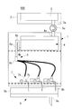
- a cell culture system 100 according to the present embodiment is a system having the configuration shown in FIGS. 1A and 1B, and is a system for exchanging a medium in a cell culture container (culture container) installed in an incubator.
- the medium storage means 3 is installed outside the incubator 1 and stores the medium (cell culture solution) inside.
- a temperature control means 2 is provided in order to maintain the temperature of the culture medium at a temperature suitable for storage (for example, 4 ° C.).
- the medium storage means 3 is connected to a temporary holding means 4 installed inside the incubator 1 via a tubular member (tube or the like). Since the culture medium storage means 3 is installed at a position above the temporary holding means 4 in the direction of gravity, the culture medium in the culture medium storage means 3 is supplied to the temporary holding means 4 via a tubular member (tube or the like) by gravity. The The medium supplied to the temporary holding means 4 is held in a space (holding space) in the temporary holding means 4 and warmed to a temperature in an incubator (for example, 37 ° C.) that is a temperature suitable for cell culture.
- a temperature in an incubator for example, 37 ° C.
- the tubular member connecting the medium storage means 3 and the temporary holding means 4 is provided with a supply speed adjusting means 5, and the medium flow rate in the tubular member is controlled to control the flow rate of the medium flowing from the medium storage means 3 to the temporary holding means 4.
- the supply rate of the medium can be adjusted.
- the medium heated to a temperature suitable for cell culture (for example, 37 ° C.) by the temporary holding means 4 is supplied to the cell culture container 7 through the medium supply means 6 in the incubator 1.
- the temporary holding means 4 includes a supply port 4a through which a culture medium is supplied from the culture medium holding means 3 via a tubular member, and a discharge port 4b through which the culture medium is discharged to the culture medium supply means 6.
- the installation position of the supply port 4a is arbitrary, it is preferable that the culture medium installed and supplied in the upper part of the temporary holding means 4 is dripped in internal space. Thereby, the back flow of the medium can be prevented, and the medium in the medium storage means 3 can be prevented from being contaminated (contamination occurs).
- the installation place of the discharge port 4b is preferably a place where the internal medium can be discharged to the end, that is, the bottom surface of the temporary holding means 4 or the lower part of the side surface.
- the medium supply means 6 includes a siphon mechanism 6a (medium intermittent supply mechanism).
- the siphon mechanism 6 a is connected to the discharge port 4 b of the temporary holding means 4.
- the flow path as shown in FIGS. 1A and 1B is folded. That is, the flow path of the siphon mechanism 6a extends from the discharge port 4b of the temporary holding means 4 upward to a predetermined height in the direction of gravity, and then turns back to extend downward in the direction of gravity.
- the predetermined height at which the flow path of the siphon mechanism 6a reaches upward in the direction of gravity is set to a position lower than the maximum height at which the medium retained in the temporary holding means 4 can reach in the direction of gravity (hereinafter referred to as “the height of the medium”).
- This set height is referred to as “folding point 6b”).
- folding point 6b the medium in the temporary holding means 4 is discharged through the flow path of the siphon mechanism 6a according to the siphon principle.
- the discharge continues until the height of the medium in the temporary holding means 4 reaches the discharge port 4b of the temporary holding means 4.
- the height of the medium in the temporary holding means 4 starts to rise due to the medium supplied from the medium storage means 3, and discharge occurs again when the position reaches a position higher than the turn-around point 6b of the flow path of the siphon mechanism 6a. repeat.
- the flow path of the siphon mechanism 6a rises upward in the direction of gravity from the discharge port 4b side of the temporary medium holding means 4 to the folding point 6b, passes through the folding point 6b, and descends downward in the direction of gravity to reach the branching means 6c. .
- a plurality of tubular members (tubes or the like) branch from the branching means 6c. The plurality of branched tubular members are connected to different cell culture containers 7 to supply a medium.
- the cell culture container 7 has a supply port 7a connected to the tubular member of the medium supply means 6, and a discharge port 7b for discharging the medium outside the cell culture container.
- the discharge port 7b is arranged on the side surface of the cell culture container 7, and when the amount of medium (height of the medium) in the cell culture container exceeds a certain value, the medium is discharged to the medium discharge means 8 through the discharge port 7b. ing.
- the amount of the medium retained in the cell culture container 7 is determined by the installation height of the discharge port 7b.
- the installation position of the supply port 7a is arbitrary, but the conversion efficiency of the medium can be increased by separating the distance from the discharge port 7b as much as possible.
- the medium that is installed and supplied at the top of the cell culture container 7 is dropped inside the cell culture container, the medium can be prevented from flowing back, and the medium supply means 6 and the temporary medium holding means that are arranged upstream of the system. 4. It is possible to prevent the medium in the medium storage means 3 from being contaminated (contamination occurs).
- the medium discharge means 8 includes a waste liquid holding means 8a.
- the waste liquid holding means 8a includes a waste liquid supply port 8b connected to the tubular member from the cell culture vessel 7, and a waste liquid discharge port 8c for discharging the medium outside the waste liquid holding means 8a.
- the waste liquid supply port 8b is installed on the upper surface of the waste liquid holding means 8a, and the medium supplied from the waste liquid supply port 8b is dropped in the space in the waste liquid holding means 8a and discharged through the waste liquid discharge port 8c. In this way, the medium is dropped in the space in the waste liquid holding means 8a, so that the back flow of the medium can be prevented and the inside of the cell culture container 7 can be prevented from being contaminated (contamination occurs). it can.
- the supply speed adjusting means 5 is disposed on a tubular member (tube or the like) that connects the discharge port 3a of the culture medium storage means 3 and the supply port 4a of the temporary holding means 4, and is deformed by applying an external force to the tubular member. By reducing the cross-sectional area of the cavity, the flow rate of the solution is limited to suppress the flow rate. Conversely, when the external force is released, the tubular member returns to its original state by the elastic force of the tubular member, and the flow velocity can be increased. As described above, the supply speed adjusting means 5 adjusts the flow rate of the solution flowing in the tubular member by the strength of the external force applied to the tubular member.
- FIGS. 2A to 2D Examples of how external force is applied to the tubular member by the supply speed adjusting means 5 are shown in FIGS. 2A to 2D.
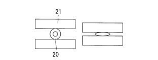
- 2A shows an example in which the tubular member 20 is sandwiched by two plate-like members 21
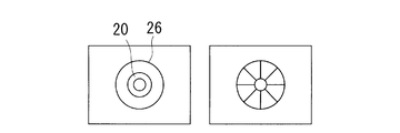
- FIG. 2B shows an example in which the tubular member 20 passed through the through hole 23 is sandwiched by a plurality of spherical (or cylindrical) members 22
- FIG. 2D shows an example in which the inner diameter of the through hole 26 through the tubular member 20 is reduced and the tubular member is deformed.
- a liquid feed pump such as a peristaltic pump may be used as the supply speed adjusting means 5.
- the user of this system sets the system to a state where the supply rate of the culture medium is 0, that is, a state where the supply is stopped, by the supply rate adjusting means 5 and replenishes the culture medium storage means 3 with the culture medium.
- a cell culture container 7 containing a culture medium and cells is prepared.
- the supply port 7a of the cell culture container 7 is used as a tubular member of the medium supply means 6, and the discharge port 7b of the cell culture container 7 is used as a waste liquid through the tubular member. Connected to the waste liquid supply port 8b of the holding means 8a.
- the user first adjusts the supply speed adjusting means 5 to set the supply speed to an appropriate speed.
- the supply rate adjusting unit 5 releases the state where the supply rate is 0, the medium starts to drip in the temporary medium holding unit 4 due to gravity.
- the adjustment of the supply speed may be set to a predetermined speed, or may be adjusted to an appropriate supply speed while being visually observed by the user.
- a culture medium is supplied to the temporary culture medium holding means 4, and the medium level in the temporary culture medium holding means 4 rises (FIG. 3A).
- the level of the medium in the temporary medium holding means 4 becomes higher than the height of the turning point 6b of the medium supply means 6 (FIG. 3B)
- the medium in the temporary holding means 4 is discharged via the medium supply means 6 according to the principle of siphon.
- the discharge continues until the height of the medium in the temporary holding means 4 reaches the discharge port 4b of the temporary holding means 4, and the discharge stops (FIG. 3D). Thereafter, the height of the medium in the temporary holding means 4 starts to rise due to the medium supplied from the medium storage means 3, and the process of discharging again when reaching a position higher than the turning point 6b of the medium supply means 6 is repeated.
- the medium discharged from the temporary holding means 4 is supplied to the plurality of cell culture containers 7 via the branching means 6 c of the medium supply means 6.
- the medium exceeding the specified amount in the cell culture container 7 is discharged from the discharge port 7b of the cell culture container 7, and is discharged outside the incubator through the waste liquid holding means 8a.
- the old medium in the cell culture vessel 7 is replaced with a new medium, and the rate at which the medium deteriorates can be reduced.
- the siphon mechanism 6a may be formed of a tubular member (tube or the like) that forms a flow path. That is, the tubular member connected to the discharge port 4b of the temporary holding means 4 only needs to have a structure that extends upward in the direction of gravity to the height of the folding point 6b and then folds back and extends downward in the direction of gravity.
- the tubular member extending downward past the turning point 6b reaches the branching means 6c, and the plurality of tubular members branched from the branching means 6c are connected to different cell culture vessels 7 to supply the medium.
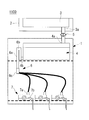
- the cell culture system 300 is a system having the configuration shown in FIGS. 4A and 4B and is a system for exchanging a medium in a cell culture container (culture container) installed in an incubator.
- the medium storage means 3 is installed outside the incubator 1 and stores the medium (cell culture solution) inside.
- a temperature control means 2 is provided in order to maintain the temperature of the culture medium at a temperature suitable for storage (for example, 4 ° C.).
- the medium storage means 3 is connected to a temporary holding means 4 installed inside the incubator 1 via a tubular member (tube or the like). Since the culture medium storage means 3 is installed at a position above the temporary holding means 4 in the direction of gravity, the culture medium in the culture medium storage means 3 is supplied to the temporary holding means 4 via a tubular member (tube or the like) by gravity. The The medium supplied to the temporary holding means 4 is warmed to a temperature in an incubator (for example, 37 ° C.) that is a temperature suitable for cell culture.
- the tubular member connecting the medium storage means 3 and the temporary holding means 4 is provided with a supply speed adjusting means 5, and the medium flow rate in the tubular member is controlled to control the flow rate of the medium flowing from the medium storage means 3 to the temporary holding means 4. The supply rate of the medium can be adjusted.
- the medium heated to a temperature suitable for cell culture (for example, 37 ° C.) by the temporary holding means 4 is supplied to the cell culture container 7 through the medium supply means 6 in the incubator 1.
- the temporary holding means 4 includes a supply port 4a through which a culture medium is supplied from the culture medium holding means 3 via a tubular member, and a discharge port 4b through which the culture medium is discharged to the culture medium supply means 6.
- the installation position of the supply port 4a is arbitrary, it is preferable that the culture medium installed and supplied in the upper part of the temporary holding means 4 is dripped in internal space. Thereby, the back flow of the medium can be prevented, and the medium in the medium storage means 3 can be prevented from being contaminated (contamination occurs).
- the installation place of the discharge port 4b is preferably the temporary holding means 4 that can discharge the internal culture medium to the end.
- the culture medium supply means 6 includes a supply gate 6d (medium intermittent supply mechanism) at the connection with the temporary culture medium holding means 4.
- the supply gate 6d is a means capable of opening and closing the flow path in accordance with the amount of the medium in the temporary holding means 4, and when the medium in the temporary medium holding means 4 exceeds a predetermined amount, the gate is opened and the medium from the temporary holding means 4 is opened. When the medium in the temporary holding means 4 is reduced to a predetermined amount, the gate is closed and the discharge of the medium from the temporary holding means 4 is blocked.
- the supply gate 6d is connected to the cell culture container 7 through a tubular member.
- the tubular member of the culture medium supply means 6 coming out from the supply gate 6d branches into a plurality of tubular members when reaching the branching means 6c.
- the plurality of branched tubular members are connected to different cell culture containers 7 to supply a medium.
- the cell culture container 7 has a supply port 7a connected to the tubular member of the medium supply means 6, and a discharge port 7b for discharging the medium outside the cell culture container.
- the discharge port 7b is arranged on the side surface of the cell culture container 7, and when the amount of medium (height of the medium) in the cell culture container exceeds a certain value, the medium is discharged to the medium discharge means 8 through the discharge port 7b. ing.
- the amount of the medium retained in the cell culture container is determined by the installation height of the discharge port 7b.
- the installation position of the supply port 7a is arbitrary, but the conversion efficiency of the medium can be increased by separating the distance from the discharge port 7b as much as possible.
- the medium discharge means 8 includes a waste liquid holding means 8a.
- the waste liquid holding means 8a includes a waste liquid supply port 8b connected to the tubular member from the cell culture vessel 7, and a waste liquid discharge port 8c for discharging the medium outside the waste liquid holding means 8a.
- the waste liquid supply port 8b is installed on the upper surface of the waste liquid holding means 8a, and the medium supplied from the waste liquid supply port 8b is dropped in the space in the waste liquid holding means 8a and discharged through the waste liquid discharge port 8c. In this way, the medium is dropped in the space in the waste liquid holding means 8a, so that the back flow of the medium can be prevented and the inside of the cell culture container 7 can be prevented from being contaminated (contamination occurs). it can.
- the supply speed adjusting means 5 is the same as that in the first embodiment.
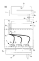
- the supply gate 6d is a means capable of opening and closing the flow path in accordance with the amount of the medium in the temporary holding means 4, and has a configuration as shown in FIGS. 5A to 5D, for example.
- 5A and 5B are examples in which the flow path is blocked by the valve 31.
- FIG. The valve 31 is disposed at a position where the flow path is blocked by the elastic force when no force is applied.
- the pressure from the culture medium in the temporary holding means 4 exceeds the threshold value, the valve 31 is opened to open the flow path. Is opened, and the medium is discharged from the temporary holding means 4.
- the pressure applied to the valve 31 from the culture medium begins to decrease.
- FIG. 5A is an aspect in which the ring member 32 prevents the valve 31 from falling in the reverse direction of the flow path
- FIG. 5B is a view in which the valve 31 is reverse to the flow path by adopting a structure in which the flow path expands in the flow direction. There is a mode for preventing the body from falling in the direction.
- FIG. 5C and 5D are examples in which the flow path is blocked by the balls 33.
- FIG. 1 In a state where no force is applied to the ball 33, the ball 33 is arranged at a position to close the flow path by being pushed by the ring member 32 by an elastic member 34 (for example, a spring), but the pressure from the medium in the temporary holding means 4 Exceeds the threshold, the ball 33 is pushed in the flow direction to open the flow path, and the medium is discharged from the temporary holding means 4.
- the pressure applied to the ball 33 from the medium decreases, and when the pressure becomes lower than the threshold, the ball 33 returns to the position where the elastic member 34 closes the flow path, and the medium from the temporary holding means 4 is returned. Is blocked.
- FIG. 5C shows a mode in which the ball 33 is pressed against the ring member 32 to block the flow path
- FIG. 5D has a structure in which the flow path expands in the flow path direction, and the ball 33 is pressed against the narrowed flow path.
- the user of this system first sets the system to a state where the supply rate is zero, that is, the state where the supply is stopped, by the supply rate adjusting means 5, and replenishes the culture medium storage means 3 with the medium.
- a cell culture container 7 containing a culture medium and cells is prepared.
- the supply port 7a of the cell culture container 7 is used as a tubular member of the medium supply means 6, and the discharge port 7b of the cell culture container 7 is used as a waste liquid through the tubular member. Connected to the waste liquid supply port 8b of the holding means 8a.
- the user first adjusts the supply speed adjusting means 5 to set the supply speed to an appropriate speed.
- the supply rate adjusting unit 5 releases the state where the supply rate is 0, the medium starts to drip in the temporary medium holding unit 4 due to gravity.
- the adjustment of the supply speed may be set to a predetermined speed, or may be adjusted to an appropriate supply speed while being visually observed by the user.
- the medium is supplied to the temporary medium holding means 4, and the amount of medium in the temporary medium holding means 4 increases.
- the gate opens, and the medium in the temporary holding means 4 begins to be discharged through the medium supply means 6, and the temporary pressure applied to the supply gate 6d.
- the discharge continues until the pressure from the medium in the medium holding means 4 decreases to the threshold value, and when the pressure decreases to the threshold value, the discharge stops. Thereafter, the amount of the medium in the temporary holding means 4 starts to increase due to the medium supplied from the medium storage means 3, and discharge occurs again when the pressure from the medium in the temporary medium holding means 4 applied to the supply gate 4d exceeds the threshold value. Repeat the process.
- the medium discharged from the temporary holding means 4 is supplied to the plurality of cell culture containers 7 via the branching means 6 c of the medium supply means 6.
- the medium exceeding the specified amount in the cell culture container 7 is discharged from the discharge port 7b of the cell culture container 7, and is discharged outside the incubator through the waste liquid holding means 8a.
- the old medium in the cell culture vessel 7 is replaced with a new medium, and the rate at which the medium deteriorates can be reduced.
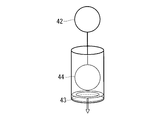
- FIGS. 6A to 6D Another aspect of the supply gate of this embodiment is shown in FIGS. 6A to 6D.
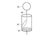
- 6A and 6B are examples in which the flow path is blocked by the valve 41.
- FIG. The valve 41 is connected to the float 42 via a string-like member 45.
- the float 42 has a structure that floats on the upper surface of the medium in the temporary holding means 4. When the medium in the temporary holding means 4 increases, the height of the upper surface of the medium rises, and the float 42 rises accordingly. As the float 42 rises, tension is generated in the string-like member 45, and the valve 41 receives an upward force by the string-like member 45.
- the valve 41 When the height of the upper surface of the medium exceeds the threshold value, the valve 41 is opened to open the flow path, and the medium is discharged from the temporary holding means 4.
- the upper surface of the culture medium in the temporary holding means 4 starts to descend, and the float 42 also descends, whereby the tension of the string-like member 45 is reduced, and the valve 41 has a flow path by its elastic force (or gravity).
- the valve 41 Returning to the position where the medium is closed, the discharge of the medium from the temporary holding means 4 is blocked. Thereafter, when the amount of the culture medium in the temporary holding means 4 increases and the height of the upper surface of the culture medium exceeds the threshold value, the valve 41 is raised again to open the flow path.
- FIG. 6A is a mode in which the valve 41 is prevented from falling in the reverse direction of the flow path by the ring member 43
- FIG. 6B is a view in which the valve 41 is reverse to the flow path by adopting a structure in which the flow path narrows in the flow direction.
- 6C and 6D are examples in which the flow path is blocked by a ball 44 instead of the valve 41.
- FIG. 6C shows a mode in which the ball 44 is pressed against the ring member 43 to block the flow path
- FIG. 6D has a structure in which the flow path is narrowed in the flow path direction, and the ball 44 is pressed against the narrowed flow path.
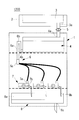
- the cell culture system 500 according to the present embodiment is different from the above embodiments in that it includes pressure load means 51 for applying pressure to the medium in the medium storage means 3.
- FIG. 7 is an example corresponding to the first embodiment, but the other embodiments are also the same.
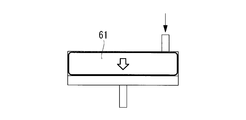
- An example of the pressure loading means 51 is a means for sending gas into the culture medium storage means 3 by a pump. Thereby, the pressure of the air layer in the culture medium storage means 3 is increased, and an external pressure can be applied to the culture medium. It is preferable to use a sterilized gas to be fed into the culture medium storage means 3.
- gas (or liquid) is fed into the bag-like member 61, and pressure is applied to the culture medium with the bag having an increased volume.
- the member 62 may be used to block the air layer 63 and the medium, and a gas (or liquid) may be sent to the air layer 63 to apply pressure to the medium using the isolation member 62. This can reduce the risk of medium contamination. As shown in FIG.
- the weight 65 having a predetermined weight is placed on the upper portion of the separating member 64 for isolation.
- a constant pressure may be applied to the member 64.
- the medium holding means and the partition member are structured like a syringe cylinder and a pusher (plunger), respectively, and the partition member, which is a pusher (plunger), is mechanically moved to apply pressure to the medium inside the medium holding means. It is okay to spend.
- the movement of the partition member may be controlled by the control unit in a wired or wireless manner.
- the medium holding means has a cylindrical structure
- the partition wall member has a disk-like structure that fits on the inner wall of the cylindrical structure
- the screw structure that meshes with the inner wall of the cylindrical structure and the outer periphery of the disk-like structure.
- the pressure load means 51 is preferably controlled so that the pressure in the culture medium storage means 3 does not rise above a certain level.
- the culture medium storage unit 3 does not necessarily have to be installed at a higher position than the temporary holding unit 4.
- the temporary holding means 4 is not necessarily installed at a position higher than the medium supply means 6.
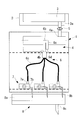
- the cell culture system 600 As shown in FIG. 9, the cell culture system 600 according to this embodiment is different from the above embodiments in that it includes negative pressure supply means 71 for applying a negative pressure to the discharge port 7 b of the cell culture container 7. ing. Other than that is the same as each said embodiment.
- FIG. 9 is an example corresponding to the first embodiment, but the other embodiments are also the same.
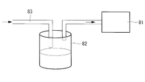
- Examples of the negative pressure supply means 71 include a means provided with a pump 81 and a waste liquid container 82 as shown in FIG.
- the suction port 83 of the negative pressure supply means 71 By connecting the suction port 83 of the negative pressure supply means 71 to the waste liquid discharge port 8b of the waste liquid holding means 8a, the inside of the waste liquid holding means 8a is set to a negative pressure, and the discharge port 7b of the cell culture vessel 7 is set to a negative pressure. It is possible to aspirate the culture medium from the container 7.
- a liquid feed pump such as a peristaltic pump may be used as a pump for the negative pressure supply means. In this case, a liquid feed pump may be installed on the tubular member of the suction port 83.
- the cell culture system 700 can be remotely operated wirelessly or wired by the control unit 19 in which the supply speed adjusting means 5 is installed outside the incubator. It has become. Other than that is the same as each said embodiment.
- FIG. 11 is an example corresponding to the first embodiment, but the other embodiments are also the same.
- the supply speed adjusting means 5 is capable of exchanging information with a control unit 19 installed outside the incubator by wireless or wired, and remotely supplies a solution such as a medium flowing in a tubular member (tube or the like).
- the flow rate can be controlled.
- the user remotely adjusts the supply speed adjusting means 5 by the control unit 19 to set the supply speed to an appropriate speed.
- the supply speed may be adjusted to a predetermined speed, or may be adjusted to an appropriate supply speed while monitoring the dropping speed with a monitoring system (not shown).
- the user can remotely start medium exchange at any timing during cell culture or can remotely change the supply rate.
- a system not shown
- it can start medium exchange remotely at any time during cell culture according to the state of cells, or remotely The feeding speed can be changed.
- the user can work without entering the work space, so that the labor and cost of changing to disposable work clothes can be reduced, and contamination of the cell culture system by bacteria etc. can be reduced. Risk can be reduced.
- the control unit 19 of this embodiment can exchange information with the temperature control means 2, the pressure application means 51, and the negative pressure supply means 71 in each of the above embodiments wirelessly or by wire, and can control them remotely. Also good. As a result, the efficiency of remote work by the user can be increased.
- the discharge port of the cell culture container is the mode shown in FIG. 12A, that is, the discharge port 7 b is arranged on the side surface of the cell culture container 7, and the amount of medium (height of the medium) in the cell culture container is constant.
- the mode in which the medium is discharged to the medium discharging unit 8 through the discharge port 7b is shown.
- the present invention is not limited to this.
- the modes shown in FIGS. 12A, 12B, 12C, and 12D are not limited to this.
- the modes shown in FIGS. 12A, 12B, 12C, and 12D are examples of the modes shown in FIGS. 12A, 12B, 12C, and 12D .
- the mode of FIG. 12B and FIG. 12C is a mode provided with the mechanism (discharge siphon mechanism 7d) similar to the siphon mechanism 6a of the culture medium supply means 6. That is, the discharge siphon mechanism 7d has a structure in which a flow path extends upward to a predetermined height in the direction of gravity from the discharge port 7b of the cell culture container, and then the flow path folds back and extends downward in the direction of gravity.
- the predetermined height at which the flow path extends upward in the direction of gravity is set to a position lower than the maximum height that the medium retained in the cell culture container can reach in the direction of gravity (hereinafter, this set height is referred to as the “turning point”). 7e ").
- the discharge siphon mechanism 7d functions as a medium intermittent discharge mechanism.
- the aspect of FIG. 12D is an aspect applicable to the system provided with the negative pressure supply means 71 for applying a negative pressure to the cell culture container 7.
- the tubular member of the medium discharge means 8 penetrates through the discharge port 7b of the cell culture container and extends from the bottom surface of the cell culture container to a predetermined height (7f).
- the predetermined height (7f) is set according to the type of cells to be cultured and the culture conditions.
- FIGS. 12A to 12D show a flask-like cell culture container, but a petri-like cell culture container or the like may be used as shown in FIGS. 13A to 13D.
- FIGS. 13A to 13D portions corresponding to FIGS. 12A to 12D are assigned the same numbers.
- a flask-like culture container is shown as a cell culture container to be used in the drawings, but a petri dish-like culture container or the like may be used as shown in FIGS. 13A to 13D.
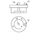
- a cell culture container having a threshold for forming a flow path may be used. If the supply port 141 and the discharge port 142 are installed at positions separated along the flow path using the container, the exchange efficiency of the medium is improved.
- FIG. 15A is an example corresponding to 1st Embodiment, other embodiment is also the same.
- a backup discharge port 4c may be installed in the temporary holding means 4. If the backup discharge port 4c is connected to the medium supply means 6 (for example, the branching means 6c) by a tubular member, the medium is removed when the medium in the temporary holding means 4 reaches the backup discharge port 4c without the siphon mechanism 6a functioning. It can be discharged to the medium supply means.
- the tubular member from the backup discharge port 4c may be connected to the medium discharge means 8 instead of the medium supply means 6, or may be connected to the medium storage means 3, for example.
- FIG. 15B is an example corresponding to the first embodiment, but the other embodiments are also the same.
- the medium storage means 3 is connected to the temporary holding means 4 via a tubular member (tube or the like), and the medium storage means 3 is installed at a position higher than the temporary holding means 4 in the direction of gravity. Therefore, although the culture medium in the culture medium storage means 3 has been shown to be supplied to the temporary holding means 4 via a tubular member (such as a tube) by gravity, for example, as shown in FIG. 16, the culture medium storage means and the temporary storage means A liquid feeding pump 5a such as a peristaltic pump may be installed as a supply speed adjusting means in a tubular member (tube or the like) connecting the medium, and the medium may be supplied from the medium storage means 3 to the temporary holding means 4.
- a liquid feeding pump 5a such as a peristaltic pump
- the culture medium holding means 3 does not necessarily have to be installed at a position above the temporary holding means 4 in the direction of gravity, and the degree of freedom of the installation place of the culture medium holding means 3 is increased.
- the liquid feed pump 5a such as a peristaltic pump may be remotely operated by the control means. The remote operation may be wired or wireless.
- FIG. 16 is an example corresponding to the first embodiment, but the other embodiments are also the same.
- the medium supply means 6 may include a supply speed adjusting means 5b.
- the installation location is preferably installed upstream of the branching means 6c.
- the configuration of the supply speed adjusting means 5b may be the same as that of the supply speed adjusting means 5 connected to the medium storage means 3 and the temporary holding means, which is installed in a tubular member (tube or the like).
- the control means may be remotely operated by wire or wirelessly.
- the waste liquid discharged from the discharge port of the culture container has been shown to be discharged through the waste liquid holding means.
- FIG. 18A is an example corresponding to 1st Embodiment, other embodiment is also the same.
- the suction port of the negative pressure supply means may be connected to each discharge port of the cell culture container.
- the medium temperature monitoring means for monitoring the medium temperature may be installed in the temporary holding means. At this time, information on the medium temperature monitored by the medium temperature monitoring means may be sent to the control unit remotely. As a result, it is possible to prevent a medium having a temperature not suitable for cell culture from being erroneously supplied.
- the medium exchange efficiency can be improved by making the amount of the medium retained in the cell culture container as small as possible. What is necessary is just to optimize the quantity of the culture medium hold
- a control unit installed outside the incubator can exchange information wirelessly or by wire with a temperature control unit, a pressure applying unit, a negative pressure supply unit, a liquid feed pump in each of the above embodiments, and remotely. You may be able to control them. As a result, the efficiency of remote work by the user can be increased.
- control unit may remotely operate the medium replacement based on a schedule (program) set in advance by the user.
- the temporary holding means may be installed outside the incubator.
- a temperature control means for maintaining the solution in the temporary holding means at a temperature suitable for cell culture (for example, 37 ° C.).
- the waste liquid holding unit may be installed outside the incubator.
- the waste liquid holding unit may be installed in the incubator.
- control unit of the present invention is a PC, and the PC can perform control executed by the control unit in each of the above embodiments. That is, the control unit is, for example, a PC having a CPU and a memory, and the function as the control unit is realized by the CPU executing a control program described in the memory.
- the medium temperature in the medium storage means 3 may be set to an appropriate temperature depending on the culture conditions. You may maintain at 37 degreeC with the temperature control means 2.
- FIG. Moreover, the culture medium storage means 3 may be installed in the incubator. In this case, the temperature control means 2 may be omitted if the culture medium temperature is maintained at 37 ° C.
- the medium storage means and the temporary medium holding means are means capable of holding a culture medium and other solutions (for example, a washing solution) and function as solution holding means.
- a culture medium and other solutions for example, a washing solution
- Each of the medium storage means and the temporary medium holding means functions as a solution holding means, and both means function as a solution holding means as a unit.
- medium storage means for holding a medium for culturing cells
- a temporary holding means connected to the medium storage means, a holding space for temporarily holding the medium supplied from the medium storage means, and a discharge port for discharging the medium
- Medium supply means connected to the discharge port of the temporary holding means and supplying the medium discharged from the temporary holding means to a cell culture container
- Medium discharge means for discharging the medium from the cell culture vessel
- a cell culture system comprising:
- the medium supply means can provide a cell culture system provided with a medium intermittent supply mechanism for supplying the medium discharged from the temporary holding means intermittently to the cell culture container at a predetermined cycle.
- medium storage means for holding a medium for culturing cells
- a temporary holding means connected to the medium storage means, a holding space for temporarily holding the medium supplied from the medium storage means, and a discharge port for discharging the medium
- Medium supply means connected to the discharge port of the temporary holding means and supplying the medium discharged from the temporary holding means to a cell culture container
- Medium discharge means for discharging the medium from the cell culture vessel
- a cell culture system comprising:
- the medium discharge means can provide a cell culture system provided with a medium intermittent discharge mechanism for discharging the medium inside the cell culture container to the outside intermittently at a predetermined cycle.
- the siphon mechanism 6a is installed outside the temporary holding unit 4.
- the tubular member forming the flow path of the siphon mechanism 6a extends upward from the discharge port 4b of the temporary holding means 4 toward the inside of the temporary holding means 4 to a predetermined height in the gravitational direction, and then turns back in the direction of gravity. It has a structure that extends downward.
- the end of the tubular member extending downward in the direction of gravity has a structure having an opening 6d in the vicinity of a gap from the bottom surface of the temporary holding means 4.
- the predetermined height at which the flow path of the siphon mechanism 6a reaches upward in the direction of gravity is set to a position lower than the maximum height at which the medium retained in the temporary holding means 4 can reach in the direction of gravity (hereinafter referred to as “the height of the medium”). This set height is referred to as “folding point 6b”).
- the siphon mechanism 6a of the present invention is a mechanism provided with a flow channel capable of intermittently supplying the medium from the temporary holding means 4 to the cell culture container according to the siphon principle.
- a cell culture container comprising a supply port for supplying a culture medium, a discharge port for discharging the culture medium, and a tubular member (discharge siphon mechanism) connected to the discharge port,
- the tubular member can provide a cell culture container that forms a flow path capable of intermittently discharging the medium in the cell culture container according to the principle of siphon.
- the cell culture vessel 7 illustrated in FIGS. 12B, 12C, 13B, and 13C can be provided. That is, the cell culture vessel 7 includes a supply port 7a for supplying a culture medium, a discharge port 7b for discharging the culture medium, and a tubular member (discharge siphon mechanism) connected to the discharge port 7b.
- the outlet 7b is disposed on the side of the container at a predetermined height from the bottom of the container, and the tubular member is positioned above the discharge port 7b in the direction of gravity and lower than the maximum height in the direction of gravity of the space in the container. It is the cell culture container 7 which forms the flow path to pass.
- the cell culture container 7 illustrated in FIGS. 20A and 20B can be provided. That is, the cell culture container 7 includes a supply port 7a for supplying a culture medium, a discharge port 7b for discharging the culture medium, and a tubular member (discharge siphon mechanism) connected to the discharge port 7b.
- the member is installed inside the cell culture container 7 and forms a flow path that passes through a position above the discharge port 7b in the direction of gravity and lower than the maximum height in the direction of gravity of the space in the container, and the discharge port of the tubular member
- the other end opposite to the end connected to 7b is the cell culture container 7 having an opening in the vicinity of the gap from the bottom surface of the cell culture container 7.
- the medium supply means 6 for supplying a medium to the inside of the cell culture container 7 can be connected to the supply port of the cell culture container 7 to form a cell culture system.
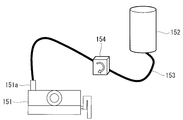
- a medium storage container 152 and a supply port 151a may be connected by a tubular member 153 such as a tube, and a liquid feed pump 154 may be installed on the tubular member 153.
- the supply port may be disposed on the upper surface of the cell culture vessel 7 and the medium may be dropped from the supply port onto the upper surface of the medium by the medium supply means 6.
- a medium is supplied into the cell culture container 7 by the medium supply means 6, and when the medium in the cell culture container 7 exceeds a predetermined amount, the discharge siphon mechanism 6a is set in accordance with the principle of siphon.
- the medium is discharged to a height, and the old medium and the new medium can be intermittently replaced.
- FIG. 22A An example of the cell culture container in this embodiment is shown in FIG. 22A.
- a culture medium and cells are accommodated in the cell culture bag 162 made of a porous membrane.
- the cell culture bag 162 is stored in the dialysis container 161 in a state immersed in a solution such as dialysis solution.
- the dialysis container 161 includes a supply port 161a for supplying a solution to the inside and a discharge port 161b for discharging the solution to the outside.
- the dialysis container 161 and the cell culture bag 162 function as the cell culture container in each of the above embodiments and modifications thereof.
- FIG. 22B Another example of the cell culture container is shown in FIG. 22B.
- a culture medium and cells are stored in the culture container 164.
- a solution such as dialysate is stored inside the dialysis bag 163 made of a porous membrane, and stored in the culture vessel 164 while immersed in a culture medium.
- the dialysis bag 163 includes a supply port 163a for supplying a solution to the inside and a discharge port 163b for discharging the solution to the outside.
- the dialysis bag 163 and the culture container 164 function as the cell culture container in each of the above embodiments and modifications thereof. According to this embodiment, the present invention can be applied not only to adherent cells but also to floating cells.
- Solution storage means for holding the solution
- Temporary holding means connected to the solution storage means, temporarily holding a solution supplied from the solution storage means, and a discharge port for discharging the solution
- a solution supply means connected to the discharge port of the temporary holding means and supplying the solution discharged from the temporary holding means to a cell culture container
- Discharging means for discharging the solution from the cell culture vessel
- a cell culture system comprising: The cell culture container is connected to the solution supply means at a position below the solution supply means in the direction of gravity, The solution supply means can provide a cell culture system provided with a flow path capable of intermittently supplying the solution from the temporary holding means to the cell culture container according to the principle of siphon.
- Temporary holding means having a solution storage means for holding the solution, a holding space for temporarily holding the solution supplied from the solution storage means, and a discharge port for discharging the solution, connected to the solution storage means
- a solution supply means connected to the discharge port of the temporary holding means and supplying the solution discharged from the temporary holding means to a cell culture container;
- Discharging means for discharging the solution from the cell culture vessel;
- a cell culture system comprising: The cell culture container is connected to the solution supply means at a position below the solution supply means in the direction of gravity, The solution supply means can provide a cell culture system including a supply gate that opens a flow path when a medium in the holding space reaches a predetermined amount.
Landscapes
- Health & Medical Sciences (AREA)
- Chemical & Material Sciences (AREA)
- Organic Chemistry (AREA)
- Life Sciences & Earth Sciences (AREA)
- Engineering & Computer Science (AREA)
- Bioinformatics & Cheminformatics (AREA)
- Zoology (AREA)
- Wood Science & Technology (AREA)
- Sustainable Development (AREA)
- Microbiology (AREA)
- Biotechnology (AREA)
- Biomedical Technology (AREA)
- Biochemistry (AREA)
- General Engineering & Computer Science (AREA)
- General Health & Medical Sciences (AREA)
- Genetics & Genomics (AREA)
- Clinical Laboratory Science (AREA)
- Analytical Chemistry (AREA)
- Apparatus Associated With Microorganisms And Enzymes (AREA)
Abstract
インキュベータ内に設置された細胞培養容器中の培地を簡易に自動で交換可能にすることを目的として、本発明の細胞培養システムは、細胞を培養するための培地を保持する培地保存手段(3)と、培地保存手段(3)と連結し、培地保存手段(3)から供給された培地を一時保持するための保持空間と、培地を排出するための排出口を備えた一時保持手段(4)と、該一時保持手段(4)の排出口と連結し、一時保持手段(4)から排出された培地を細胞培養容器(7)に供給する培地供給手段(6)と、細胞培養容器(4)から培地を排出する排出手段(8)とを備えた細胞培養システムであって、培地供給手段は、一時保持手段から排出された培地を、所定の周期で断続的に細胞培養容器(4)に供給するための培地断続供給機構を備える。
Description
本発明は、細胞培養容器内の培地を自動交換可能な細胞培養システムおよび細胞培養容器に関するものである。
近年、幹細胞研究や再生医療の進展に伴い、臨床用途の細胞を大量に調製することが要求されている。臨床用途の細胞の調製には厳しい基準に適った環境での作業が求められ、そのため、作業者が作業空間に立ち入る際には使い捨ての作業着に着替えたりするなど大変な手間とコストが発生している。また、作業者による作業工程は培養系が汚染される機会となっている。したがって、作業者が作業空間に立ち入り作業をする回数をできる限り少なくし、可能な作業については人手によらず自動で行うことが求められている。
細胞を培養するには定期的に培地(細胞培養液)の交換が必要となるが、培地交換は培養系の汚染(コンタミネーション)のリスクを伴い、可能な限り人手を介さずに自動で行えることが望ましい。自動で培地を交換するシステムとして、搬送ロボットにより培養容器をインキュベータと培地交換ロボットの間で移動させるシステムが知られている(特許文献1)。
細胞を培養するには定期的に培地(細胞培養液)の交換が必要となるが、培地交換は培養系の汚染(コンタミネーション)のリスクを伴い、可能な限り人手を介さずに自動で行えることが望ましい。自動で培地を交換するシステムとして、搬送ロボットにより培養容器をインキュベータと培地交換ロボットの間で移動させるシステムが知られている(特許文献1)。
臨床用途の細胞の調製には厳しい基準が設定されており、培養系が汚染されるリスクはなるべく排除する必要があるため、培地交換の過程を自動化することが有利となるが、特許文献1のような自動培地交換システムでは、搬送ロボット等を採用するためシステムが非常に複雑となり、システムエラーを起こすリスクが高くなる。また、培養容器をインキュベータから出し入れするため、培養容器内の細胞に温度変化のよるストレスがかかることになる。それをさけるためにシステムをインキュベータ内に設置すると、インキュベータ内は多湿の環境にあるため、機械的、電気的な構造物がトラブルを起こすリスクがあり、インキュベータ内のシステム構成物はなるべく簡単な構成が好ましい。
本発明は、上述した事情に鑑みてなされたものであって、細胞培養空間における細胞培養容器内の培地を簡易に自動で交換することができるとともに、システムを簡単な構成とすることでシステムトラブルの発生リスクを軽減できる細胞培養システムおよび細胞培養容器を提供する。
本発明の一態様は、細胞を培養するための培地を保持する培地保存手段と、前記培地保存手段と連結し、前記培地保存手段から供給された培地を一時保持するための保持空間と、培地を排出するための排出口を備えた一時保持手段と、該一時保持手段の前記排出口と連結し、前記一時保持手段から排出された培地を細胞培養容器に供給する培地供給手段と、前記細胞培養容器から培地を排出する培地排出手段と、を備えた細胞培養システムであって、前記細胞培養容器は、前記培地供給手段より重力方向で下の位置で前記培地供給手段と連結し、前記培地供給手段は、サイフォンの原理により前記一時保持手段から前記細胞培養容器に培地を断続的に供給することができる流路を備えている細胞培養システムである。
本態様によって、ユーザがその場にいない場合も培地等の溶液を自動で細胞培養容器に対して供給・排出することが可能である。サイフォンの原理を利用しており、簡単な構成によって培地等の溶液を断続的に細胞培養容器に供給することができる。
本発明のほかの一態様は、細胞を培養するための培地を保持する培地保存手段と、前記培地保存手段と連結し、前記培地保存手段から供給された培地を一時保持するための保持空間と、培地を排出するための排出口を備えた一時保持手段と、該一時保持手段の前記排出口と連結し、前記一時保持手段から排出された培地を細胞培養容器に供給する培地供給手段と、前記細胞培養容器から培地を排出する培地排出手段と、を備えた細胞培養システムであって、前記細胞培養容器は、前記培地供給手段より重力方向で下の位置で前記培地供給手段と連結し、前記培地供給手段は、前記保持空間内の培地が所定の量に達した時に流路を開く供給ゲート備えている細胞培養システムである。
本態様によって、ユーザがその場にいない場合も培地等の溶液を自動で細胞培養容器に対して供給・排出することが可能である。一時保持手段に内の培地の量に応じて開閉するゲートを採用しており、簡単な構成によって培地等の溶液を断続的に細胞培養容器に供給することができる。
また、上記態様においては、前記培地供給手段は、前記細胞培養容器に供給する前の培地を、前記一時保持手段の排出口より重力方向で上の位置かつ前記保持空間の重力方向で最大の高さより低い位置を通過させる流路を備えていても良い。
また、上記態様においては、前記排出口は、前記一時保持手段底面から所定の高さの位置の前記一時保持手段側面に配置され前記培地供給手段は、前記排出口から前記一時保持手段の外部に流路を形成していても良い。
また、上記態様においては、前記培地供給手段は、前記一時保持手段の排出口から前記一時保持手段の内部に流路を形成し、前記一時保持手段の排出口に接続した前記培地供給手段の端とは逆の端が、前記一時保持手段の底面から間隙を開けた近傍に開口部を有していても良い。
また、上記態様においては、前記供給ゲートが、前記保持空間内の培地が所定の重さに達したとき、または前記保持空間内の培地上面が所定の高さに達したときに流路を開いても良い。このことにより、簡単な構成により培地等の溶液を断続的に細胞培養容器に供給することができる。
また、上記態様においては、前記細胞培養容器は、内部の培地上面の高さが所定の高さに達したときに培地を外部に排出するための排出口を備えていても良い。このことにより、簡単な構成によって培地等の溶液を自動で細胞培養容器に対して供給・排出することが可能である。
また、上記態様においては、前記培地保存手段から前記一時保持手段に供給される培地の供給速度を制御する供給速度調整手段を備えていても良い。このことにより、細胞培養容器に培地を断続的に供給する周期を任意に設定することが可能になる。
本発明のほかの一態様は、培地を供給するための供給口と、培地を排出するための排出口と、該排出口に接続した管状部材を備えた細胞培養容器であって、前記管状部材は、サイフォンの原理により前記細胞培養容器内の培地を断続的に排出することができる流路を形成する細胞培養容器である。
本態様によって、前記管状部材は、前記排出口より重力方向で上の位置かつ前記細胞培養容器内の空間の重力方向で最大の高さより低い位置を通過する流路を形成しても良い。
また、上記態様においては、前記排出口は、前記細胞培養容器の底面から所定の高さの位置の前記細胞培養容器の側面に配置され、前記管状部材は、前記排出口から前記細胞培養容器の外部に流路を形成しても良い。
また、上記態様においては、前記管状部材は、前記排出口から前記細胞培養容器の内部に流路を形成し、前記管状部材の前記排出口に接続した端とは逆の端が、前記細胞培養容器の前記底面から間隙を開けた近傍に開口部を有していても良い。
本発明のほかの一態様は、上記に記載の細胞培養容器と、該細胞培養容器の前記供給口から内部に培地を供給する培地供給手段とを備えた細胞培養システムである。
本発明によれば、作業者がその場にいなくても培地交換が可能となり、作業者が作業空間に立ち入る回数を減らすことができる。このことにより、使い捨ての作業着に着替えたりするなどの手間とコストを削減できるとともに、細菌等による細胞培養系へのコンタミネーションのリスクを低減することができる。また、システムの構成が単純なので、システムエラーのリスクを軽減することができ、エラーにより培養条件に影響を及ぼしてしまうリスクを回避することができる。
本発明の実施形態に係る細胞培養システムについて、図面を参照して以下に説明する。
(第1実施形態)
本実施形態に係る細胞培養システム100は、図1Aおよび図1Bに示される構成のシステムであり、インキュベータ内に設置された細胞培養容器(培養容器)内の培地を交換するシステムである。
(第1実施形態)
本実施形態に係る細胞培養システム100は、図1Aおよび図1Bに示される構成のシステムであり、インキュベータ内に設置された細胞培養容器(培養容器)内の培地を交換するシステムである。
培地保存手段3は、インキュベータ1の外部に設置されており、内部に培地(細胞培養液)を保存するためのものである。培地の温度を保存に適した温度(例えば4℃)に維持するために温度制御手段2を備えている。
培地保存手段3は管状部材(チューブ等)を介してインキュベータ1の内部に設置された一時保持手段4に連結している。培地保存手段3は一時保持手段4よりも重力方向で上の位置に設置されているため、培地保存手段3内の培地は重力により管状部材(チューブ等)を介して一時保持手段4に供給される。一時保持手段4に供給された培地は、一時保持手段4内の空間(保持空間)で保持され、細胞培養に適した温度であるインキュベータ内の温度(例えば37℃)に温められる。
培地保存手段3と一時保持手段4をつなぐ管状部材には供給速度調整手段5が備えられており、管状部材内を流れる培地の流速を制御することで培地保存手段3から一時保持手段4への培地の供給速度を調整することができる。
培地保存手段3と一時保持手段4をつなぐ管状部材には供給速度調整手段5が備えられており、管状部材内を流れる培地の流速を制御することで培地保存手段3から一時保持手段4への培地の供給速度を調整することができる。
一時保持手段4で細胞培養に適した温度(例えば37℃)に温められた培地は、インキュベータ1内で培地供給手段6を介して細胞培養容器7に供給される。一時保持手段4は管状部材を介して培地保持手段3から培地が供給される供給口4aと、培地供給手段6に培地を排出する排出口4bを備えている。供給口4aの設置位置は任意であるが、一時保持手段4の上部に設置して供給された培地を内部空間で滴下させることが好ましい。このことにより、培地の逆流を防ぐことができ、培地保存手段3内の培地が汚染される(コンタミネーションが起こる)ことを防止することができる。一方、排出口4bの設置場所は、内部の培地を最後まで排出できる場所、つまり、一時保持手段4の底面または、側面の下部が好ましい。
培地供給手段6はサイフォン機構6a(培地断続供給機構)を備えている。サイフォン機構6aは一時保持手段4の排出口4bに接続している。図1Aおよび図1Bに示すような流路が折り返した構造をしている。つまり、サイフォン機構6aの流路は、一時保持手段4の排出口4bから重力方向で上方に所定の高さまで延び、そこで折り返して重力方向の下方に延びる構造をしている。ここで、サイフォン機構6aの流路が重力方向で上方に達する所定の高さは、一時保持手段4内に保持される培地が重力方向で達し得る最高の高さより低い位置に設定される(以降この設定高さを「折り返し点6b」という)。このことにより、一時保持手段4内の培地の高さが折り返し点6bの高さ以上に達すると、サイフォンの原理に従い、一時保持手段4内の培地はサイフォン機構6aの流路を介して排出され始め、一時保持手段4内の培地の高さが一時保持手段4の排出口4bに達するまで排出が継続する。その後、培地保存手段3から供給される培地により一時保持手段4内の培地に高さは上昇し始め、サイフォン機構6aの流路の折り返し点6bより高い位置に達すると再び排出が起こるという工程を繰り返す。
サイフォン機構6aの流路は、一時培地保持手段4の排出口4b側から重力方向で上方に折り返し点6bまで上昇し、折り返し点6bを通過して重力方向で下方に下降し分岐手段6cに達する。分岐手段6cからは複数の管状部材(チューブ等)が分岐する。分岐した複数の管状部材はそれぞれ別の細胞培養容器7に接続し培地を供給する。
細胞培養容器7は培地供給手段6の管状部材と接続する供給口7aと、細胞培養容器外に培地を排出する排出口7bを有している。排出口7bは細胞培養容器7の側面に配置され、細胞培養容器内の培地量(培地の高さ)が一定値を超えると排出口7bを通して培地が培地排出手段8へ排出されるようになっている。細胞培養容器7内に保持される培地の量は排出口7bの設置高さによりが決定されることになる。一方、供給口7aの設置位置は任意であるが、排出口7bとの距離を可能な限り離した方が培地の変換効率を上げることができる。また、細胞培養容器7の上部に設置して供給された培地を細胞培養容器内部で滴下させると培地の逆流を防ぐことができ、システム上流に配置されている培地供給手段6、一時培地保持手段4、培地保存手段3内の培地が汚染される(コンタミネーションが起こる)ことを防止することができる。
培地排出手段8は、廃液保持手段8aを備え、廃液保持手段8aは細胞培養容器7からの管状部材と接続する廃液供給口8bと、廃液保持手段8a外に培地を排出する廃液排出口8cを有している。廃液供給口8bは廃液保持手段8aの上面に設置されており、廃液供給口8bから供給された培地は廃液保持手段8a内の空間を滴下され、廃液排出口8cを通して排出される。このように、培地が廃液保持手段8a内の空間を滴下されることで、培地の逆流を防ぐことができ、細胞培養容器7内が汚染される(コンタミネーションが起こる)ことを防止することができる。
次に、供給速度調整手段5について説明をする。
供給速度調整手段5は培地保存手段3の排出口3aと一時保持手段4の供給口4aをつなぐ管状部材(チューブ等)に配置されており、管状部材に外力を加えて変形させ、管状部材内腔の断面積を小さくすることで溶液の流量を制限して流速を抑制する。逆に外力を解除すると、管状部材の弾性力により管状部材が元の状態に戻り、流速を上げることができる。このように、供給速度調整手段5は管状部材に対する外力の強弱により管状部材内に流れる溶液の流速を調整する。供給速度調整手段5による管状部材への外力の加え方について図2Aから図2Dに例を示す。図2Aは2枚の板状部材21により管状部材20を挟む例、図2Bは複数の球状(または円柱状)部材22により貫通穴23に通した管状部材20を挟む例、図2Cはシャッター状部材24で貫通穴25に通した管状部材20を挟む例、図2Dは管状部材20を通した貫通穴26の内径が小さくなり管状部材を変形させる例である。これ以外でも外力を加えて管状部材を変形させることができる機構であれば良い。
また、供給速度調整手段5としてペリスタポンプ等の送液ポンプを使用しても良い。この場合、培地保存手段3は一時保持手段4より重力方向で上方に配置する必要はなくなり、培地保存手段3の設置場所の自由度があがる。
次に、本実施形態に係る培地交換システム100を用いて培地を交換する手順について一例を説明する。
本システムのユーザは、まず供給速度調整手段5により、培地の供給速度が0の状態つまり供給が止まった状態にシステムを設定し、培地保存手段3に培地を補充する。培地及び細胞が入った細胞培養容器7を用意し、インキュベータ内で細胞培養容器7の供給口7aを培地供給手段6の管状部材に、細胞培養容器7の排出口7bを管状部材を介して廃液保持手段8aの廃液供給口8bに接続する。
培地交換が必要になった際、ユーザはまず供給速度調整手段5を調整して供給速度を適当な速度にする。供給速度調整手段5により供給速度が0の状態を解除すると、一時培地保持手段4内で培地は重力により滴下し始める。供給速度の調整はあらかじめ決められた速度に設定しても良いし、ユーザが目視しながら適当な供給速度に調整しても良い。
一時培地保持手段4に培地が供給され、一時培地保持手段4内の培地液面が上昇する(図3A)。一時培地保持手段4内の培地液面が培地供給手段6の折り返し点6bの高さより高くなると(図3B)サイフォンの原理に従い、一時保持手段4内の培地は培地供給手段6を介して排出され始め(図3C)、一時保持手段4内の培地の高さが一時保持手段4の排出口4bに達するまで排出が継続し、排出が停止する(図3D)。その後、培地保存手段3から供給される培地により一時保持手段4内の培地に高さは上昇し始め、培地供給手段6の折り返し点6bより高い位置に達すると再び排出が起こるという工程を繰り返す。
一時保持手段4から排出された培地は、培地供給手段6の分岐手段6cを介して複数の細胞培養容器7に供給さる。細胞培養容器7内で規定量を超えた培地は細胞培養容器7の排出口7bから排出され、廃液保持手段8aを介してインキュベータ外に排出される。このことにより、細胞培養容器7内の古くなった培地は新しい培地と置き換わり、培地の劣化する速度を遅くすることが可能となる。
本実施形態において、サイフォン機構6aとして図1Bに示すように管状部材(チューブ等)が流路を形成していても良い。つまり、一時保持手段4の排出口4bに接続した管状部材が重力方向で上方に折り返し点6bの高さまで延び、そこで折り返して重力方向の下方に延びる構造をしていれば良い。折り返し点6bを過ぎて下方に延びた管状部材は分岐手段6cに達し、分岐手段6cから分岐した複数の管状部材はそれぞれ別の細胞培養容器7に接続し培地を供給する。
(第2実施形態)
本実施形態に係る細胞培養システム300は、図4Aおよび図4Bに示される構成のシステムであり、インキュベータ内に設置された細胞培養容器(培養容器)内の培地を交換するシステムである。
本実施形態に係る細胞培養システム300は、図4Aおよび図4Bに示される構成のシステムであり、インキュベータ内に設置された細胞培養容器(培養容器)内の培地を交換するシステムである。
培地保存手段3は、インキュベータ1の外部に設置されており、内部に培地(細胞培養液)を保存するためのものである。培地の温度を保存に適した温度(例えば4℃)に維持するために温度制御手段2を備えている。
培地保存手段3は管状部材(チューブ等)を介してインキュベータ1の内部に設置された一時保持手段4に連結している。培地保存手段3は一時保持手段4よりも重力方向で上の位置に設置されているため、培地保存手段3内の培地は重力により管状部材(チューブ等)を介して一時保持手段4に供給される。一時保持手段4に供給された培地は、細胞培養に適した温度であるインキュベータ内の温度(例えば37℃)に温められる。
培地保存手段3と一時保持手段4をつなぐ管状部材には供給速度調整手段5が備えられており、管状部材内を流れる培地の流速を制御することで培地保存手段3から一時保持手段4への培地の供給速度を調整することができる。
培地保存手段3と一時保持手段4をつなぐ管状部材には供給速度調整手段5が備えられており、管状部材内を流れる培地の流速を制御することで培地保存手段3から一時保持手段4への培地の供給速度を調整することができる。
一時保持手段4で細胞培養に適した温度(例えば37℃)に温められた培地は、インキュベータ1内で培地供給手段6を介して細胞培養容器7に供給される。一時保持手段4は管状部材を介して培地保持手段3から培地が供給される供給口4aと、培地供給手段6に培地を排出する排出口4bを備えている。供給口4aの設置位置は任意であるが、一時保持手段4の上部に設置して供給された培地を内部空間で滴下させることが好ましい。このことにより、培地の逆流を防ぐことができ、培地保存手段3内の培地が汚染される(コンタミネーションが起こる)ことを防止することができる。一方、排出口4bの設置場所は、内部の培地を最後まで排出できる一時保持手段4が好ましい。
培地供給手段6は一時培地保持手段4との接続部に供給ゲート6d(培地断続供給機構)を備えている。供給ゲート6dは一時保持手段4内の培地量に応じて流路を開閉することができる手段であり、一時培地保持手段4内の培地が所定量を超えるとゲートを開き一時保持手段4から培地を排出させ、一時保持手段4内の培地が所定量まで減るとゲートを閉じ一時保持手段4からの培地の排出を遮断する手段である。供給ゲート6dは管状部材を介して細胞培養容器7に接続している。
供給ゲート6dから出た培地供給手段6の管状部材は、分岐手段6cに達すると複数の管状部材に分岐する。分岐した複数の管状部材はそれぞれ別の細胞培養容器7に接続し培地を供給する。
供給ゲート6dから出た培地供給手段6の管状部材は、分岐手段6cに達すると複数の管状部材に分岐する。分岐した複数の管状部材はそれぞれ別の細胞培養容器7に接続し培地を供給する。
細胞培養容器7は培地供給手段6の管状部材と接続する供給口7aと、細胞培養容器外に培地を排出する排出口7bを有している。排出口7bは細胞培養容器7の側面に配置され、細胞培養容器内の培地量(培地の高さ)が一定値を超えると排出口7bを通して培地が培地排出手段8へ排出されるようになっている。細胞培養容器内に保持される培地の量は排出口7bの設置高さによりが決定されることになる。一方、供給口7aの設置位置は任意であるが、排出口7bとの距離を可能な限り離した方が培地の変換効率を上げることができる。また、細胞培養容器7の上部に設置して供給された培地を細胞培養容器7内部で滴下させると培地の逆流を防ぐことができ、システム上流に配置されている培地供給手段6、一時培地保持手段4、培地保存手段3内の培地が汚染される(コンタミネーションが起こる)ことを防止することができる。
培地排出手段8は、廃液保持手段8aを備え、廃液保持手段8aは細胞培養容器7からの管状部材と接続する廃液供給口8bと、廃液保持手段8a外に培地を排出する廃液排出口8cを有している。廃液供給口8bは廃液保持手段8aの上面に設置されており、廃液供給口8bから供給された培地は廃液保持手段8a内の空間を滴下され、廃液排出口8cを通して排出される。このように、培地が廃液保持手段8a内の空間を滴下されることで、培地の逆流を防ぐことができ、細胞培養容器7内が汚染される(コンタミネーションが起こる)ことを防止することができる。
供給速度調整手段5については、第1実施形態と同様である。
次に、供給ゲート6dについて説明をする。
供給ゲート6dは一時保持手段4内の培地量に応じて流路を開閉することができる手段であり、例えば図5Aから図5Dに示すような構成をしている。
図5Aおよび図5Bは、弁31により流路を遮断する例である。弁31はなにも力がかからない状態ではその弾性力により流路を塞ぐ位置に配置しているが、一時保持手段4内の培地からの圧力が閾値をこえると弁31が開くことで流路が開放され、一時保持手段4から培地が排出される。培地が排出されることにより弁31にかかる培地からの圧力が減少し始め、閾値より圧力が低くなると弁31はその弾性力により流路を塞ぐ位置にもどり、一時保持手段4からの培地の排出が遮断される。その後一時保持手段4内の培地の量が増加し、培地から弁31にかかる圧力が閾値をこえると再度弁31が押され流路が開くという工程を繰り返す。ここで、図5Aはリング部材32により弁31が流路の逆方向に倒れることを防ぐ態様であり、図5Bは流路が流れの方向に広がる構造をとることで弁31が流路の逆方向に倒れることを防ぐ態様ある。
図5Cおよび図5Dは、ボール33により流路を遮断する例である。ボール33はなにも力がかからない状態では、弾性部材34(例えばバネ)によりリング部材32に押されることで流路を塞ぐ位置に配置されているが、一時保持手段4内の培地からの圧力が閾値をこえるとボール33が流れ方向に押されることで流路が開放され、一時保持手段4から培地が排出される。培地が排出されることによりボール33にかかる培地からの圧力が減少し、閾値より圧力が低くなるとボール33は弾性部材34の弾性力により流路を塞ぐ位置にもどり、一時保持手段4からの培地の排出が遮断される。その後一時保持手段4内の培地の量が増加し、培地からボール33にかかる圧力が閾値をこえると再度ボール33押され流路が開くという工程を繰り返す。ここで、図5Cはボール33がリング部材32に押し付けられることで流路を塞ぐ態様であり、図5Dは流路が流路方向に広がる構造をとり、ボール33が狭まった流路に押し付けられることで流路塞ぐ態様ある。
次に、本実施形態に係る培地交換システム300を用いて培地を交換する手順について一例を説明する。
本システムのユーザは、まず供給速度調整手段5により、培地に供給速度が0の状態つまり供給が止まった状態にシステムを設定し、培地保存手段3に培地を補充する。培地及び細胞が入った細胞培養容器7を用意し、インキュベータ内で細胞培養容器7の供給口7aを培地供給手段6の管状部材に、細胞培養容器7の排出口7bを管状部材を介して廃液保持手段8aの廃液供給口8bに接続する。
培地交換が必要になった際、ユーザはまず供給速度調整手段5を調整して供給速度を適当な速度にする。供給速度調整手段5により供給速度が0の状態を解除すると、一時培地保持手段4内で培地は重力により滴下し始める。供給速度の調整はあらかじめ決められた速度に設定しても良いし、ユーザが目視しながら適当な供給速度に調整しても良い。
一時培地保持手段4に培地が供給され、一時培地保持手段4内の培地量が増加する。供給ゲート6dにかかる一時培地保持手段4内の培地からの圧力が閾値を超えるとゲートが開き、一時保持手段4内の培地は培地供給手段6を介して排出され始め、供給ゲート6dにかかる一時培地保持手段4内の培地からの圧力が閾値に減少するまで排出が継続し、閾値まで減少すると排出が停止する。その後、培地保存手段3から供給される培地により一時保持手段4内の培地量が増加し始め、供給ゲート4dにかかる一時培地保持手段4内の培地からの圧力が閾値を超えると再び排出が起こるという工程を繰り返す。
一時保持手段4から排出された培地は、培地供給手段6の分岐手段6cを介して複数の細胞培養容器7に供給さる。細胞培養容器7内で規定量を超えた培地は細胞培養容器7の排出口7bから排出され、廃液保持手段8aを介してインキュベータ外に排出される。このことにより、細胞培養容器7内の古くなった培地は新しい培地と置き換わり、培地の劣化する速度を遅くすることが可能となる。
本実施形態の供給ゲートの別の態様を図6Aから図6Dに示す。
図6Aおよび図6Bは、弁41により流路を遮断する例である。弁41はひも状部材45を介してフロート42と接続している。フロート42は一時保持手段4内の培地上面に浮く構造をしている。一時保持手段4内の培地が増加すると培地上面の高さが上昇し、それにともないフロート42も上昇をする。フロート42が上昇することでひも状部材45に張力が生じ、弁41はひも状部材45により上方に力を受けることになる。培地上面の高さが閾値を超えると弁41が開き流路が開放され、一時保持手段4から培地が排出される。培地が排出されることにより一時保持手段4内の培地上面が下降し始め、フロート42も下降することでひも状部材45の張力が減少し、弁41はその弾性力(または重力)により流路を塞ぐ位置にもどり、一時保持手段4からの培地の排出が遮断される。その後一時保持手段4内の培地の量が増加し、培地上面の高さが閾値をこえると再度弁41が引き上げられ流路が開くという工程を繰り返す。ここで、図6Aはリング部材43により弁41が流路の逆方向に倒れることを防ぐ態様であり、図6Bは流路が流れの方向に狭まる構造をとることで弁41が流路の逆方向に倒れることを防ぐ態様ある。
図6Cおよび図6Dは、弁41の代わりにボール44により流路を遮断する例である。図6Cはボール44がリング部材43に押し付けられることで流路を塞ぐ態様であり、図6Dは流路が流路方向に狭まる構造をとり、ボール44が狭まった流路に押し付けられることで流路を塞ぐ態様ある。
(第3実施形態)
本実施形態に係る細胞培養システム500は、図7に示すように、培地保存手段3内の培地に圧力をかけるための圧力負荷手段51を備えている点で上記各実施形態と異なっている。それ以外は上記各実施形態と同様である。図7は第1実施形態に対応する例であるが、他の実施形態も同様である。
本実施形態に係る細胞培養システム500は、図7に示すように、培地保存手段3内の培地に圧力をかけるための圧力負荷手段51を備えている点で上記各実施形態と異なっている。それ以外は上記各実施形態と同様である。図7は第1実施形態に対応する例であるが、他の実施形態も同様である。
圧力負荷手段51としては、培地保存手段3内にポンプにより気体を送り込む手段を例として挙げることができる。これにより、培地保存手段3内の空気層の圧力が高まり、培地に外圧を加えることが可能となる。培地保存手段3内に送り込む気体は滅菌されたものを用いるのが好ましい。図8Aに示すように袋状部材61の中に気体(または液体)を送り込み、体積が増加した袋により培地に圧力を加えたり、図8Bに示すように気密性を確保しながら移動可能な隔離部材62を用いて空気層63と培地を遮断し、空気層63に気体(または液体)を送りこみ隔離部材62により培地に圧力を加えるたりすることもできる。これにより、培地の汚染のリスクを下げることが可能となる。なお、図8Cに示すように、図8Cに示した隔離部材を用いた態様で気体(または液体)を送り込むかわりに、所定の重さの重り65を隔離部材64の上部にのせることで隔離部材64に一定の圧力をかけても良い。培地保持手段と隔壁部材がそれぞれシリンジの筒と押子(プランジャ)のような構造をしていて、押子(プランジャ)である隔壁部材を機械的に移動させて培地保持手段内部の培地に圧力をかけても良い。この場合、制御部によって有線または無線で隔壁部材の移動を制御しても良い。
また、培地保持手段が円柱状構造をし、隔壁部材がその円柱状構造の内壁に気密性を保ちながらはまる円盤状構造をし、円柱状構造の内壁と円盤状構造の外周に互いにかみ合うネジ構造を有する態様にしても良い。この場合、隔壁部材を培地保持手段の内部に取り付けて円盤周方向に回転させると隔壁部材が円柱構造の高さ方向に移動して培地保持手段内部の培地に圧力をかる(または圧力を除く)ことができる。隔壁部材の回転を機械的行い、制御部によって有線または無線で隔壁部材の回転を制御しても良い。
また、培地保持手段が円柱状構造をし、隔壁部材がその円柱状構造の内壁に気密性を保ちながらはまる円盤状構造をし、円柱状構造の内壁と円盤状構造の外周に互いにかみ合うネジ構造を有する態様にしても良い。この場合、隔壁部材を培地保持手段の内部に取り付けて円盤周方向に回転させると隔壁部材が円柱構造の高さ方向に移動して培地保持手段内部の培地に圧力をかる(または圧力を除く)ことができる。隔壁部材の回転を機械的行い、制御部によって有線または無線で隔壁部材の回転を制御しても良い。
ここで、圧力負荷手段51は、培地保存手段3内の圧力が一定以上に上がらないように制御されたものが好ましい。
なお、本実施形態においては、培地保存手段3は一時保持手段4よりも必ずしも高い位置に設置されている必要はない。また、一時保持手段4は培地供給手段6よりも必ずしも高い位置に設置されている必要はない。
なお、本実施形態においては、培地保存手段3は一時保持手段4よりも必ずしも高い位置に設置されている必要はない。また、一時保持手段4は培地供給手段6よりも必ずしも高い位置に設置されている必要はない。
(第4実施形態)
本実施形態に係る細胞培養システム600は、図9に示すように、細胞培養容器7の排出口7bに陰圧をかけるための陰圧供給手段71を備えている点で上記各実施形態と異なっている。それ以外は上記各実施形態と同様である。図9は第1実施形態に対応する例であるが、他の実施形態も同様である。
本実施形態に係る細胞培養システム600は、図9に示すように、細胞培養容器7の排出口7bに陰圧をかけるための陰圧供給手段71を備えている点で上記各実施形態と異なっている。それ以外は上記各実施形態と同様である。図9は第1実施形態に対応する例であるが、他の実施形態も同様である。
陰圧供給手段71としては、図10に示すようなポンプ81と廃液容器82を備えた手段を挙げることができる。陰圧供給手段71の吸引口83を廃液保持手段8aの廃液排出口8bと接続して廃液保持手段8a内を陰圧にし、細胞培養容器7の排出口7bを陰圧にすることで細胞培養容器7から培地を吸引することが可能である。
陰圧供給手段のポンプとしてペリスタポンプ等の送液ポンプを使用しても良い。この場合、送液ポンプを吸引口83の管状部材に設置しても良い。
陰圧供給手段のポンプとしてペリスタポンプ等の送液ポンプを使用しても良い。この場合、送液ポンプを吸引口83の管状部材に設置しても良い。
(第5実施形態)
本実施形態に係る細胞培養システム700は、図11に示すように、上記各実施形態において、供給速度調整手段5がインキュベータ外に設置された制御部19により無線または有線により遠隔的に操作可能となっている。それ以外は上記各実施形態と同様である。 図11は第1実施形態に対応する例であるが、他の実施形態も同様である。
本実施形態に係る細胞培養システム700は、図11に示すように、上記各実施形態において、供給速度調整手段5がインキュベータ外に設置された制御部19により無線または有線により遠隔的に操作可能となっている。それ以外は上記各実施形態と同様である。 図11は第1実施形態に対応する例であるが、他の実施形態も同様である。
本実施形態において、供給速度調整手段5はインキュベータ外に設置された制御部19と無線または有線により情報交換可能となっており、遠隔的に管状部材(チューブ等)内を流れる培地等の溶液の流速をコントロール可能となっている。
培地交換が必要になった際、ユーザは制御部19により遠隔的に供給速度調整手段5を調整して供給速度を適当な速度にする。供給速度の調整はあらかじめ決められた速度に設定しても良いし、図示しないモニタリングシステムで滴下速度を監視しながら適当な供給速度に調整しても良い。
培地交換が必要になった際、ユーザは制御部19により遠隔的に供給速度調整手段5を調整して供給速度を適当な速度にする。供給速度の調整はあらかじめ決められた速度に設定しても良いし、図示しないモニタリングシステムで滴下速度を監視しながら適当な供給速度に調整しても良い。
本実施形態によれば、ユーザは細胞培養中の任意のタイミングで遠隔的に培地交換を開始したり、遠隔的に供給速度を変更することができる。例えば、遠隔的に細胞の状態を監視できるシステム(図示せず)と併用することにより、細胞の状態に合わせて、細胞培養中の任意のタイミングで遠隔的に培地交換を開始したり、遠隔的に供給速度を変更することができる。こうすることで、ユーザは作業空間に入ることなく作業をすることができるので、使い捨ての作業着に着替えたりするなどの手間とコストを削減できるとともに、細菌等による細胞培養系へのコンタミネーションのリスクを低減することができる。
本実施形態の制御部19は、上記各実施形態における温度制御手段2、圧力付加手段51、陰圧供給手段71と無線または有線により情報交換可能して遠隔的にそれらをコントロール可能になっていても良い。このことにより、ユーザによる遠隔作業の効率を上げることができる。
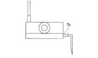
上記各実施形態において、細胞培養容器の排出口は図12Aに示す態様、つまり、排出口7bは細胞培養容器7の側面に配置され、細胞培養容器内の培地量(培地の高さ)が一定値を超えると排出口7bを通して培地が培地排出手段8へ排出されるようになっている態様を示したが、これに限らず例えば図12A、図12B、図12Cおよび図12Dに示す態様でも良い。
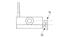
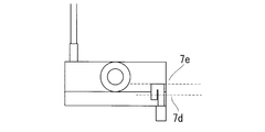
図12Bおよび図12Cの態様は、培地供給手段6のサイフォン機構6aと同様な機構(排出サイフォン機構7d)を備えた態様である。つまり、排出サイフォン機構7dは、細胞培養容器の排出口7bから重力方向で上方に所定の高さまで流路が延び、そこで折り返して重力方向の下方に流路が延びる構造をしている。流路が重力方向で上方にのびる所定の高さは、細胞培養容器内に保持される培地が重力方向で達し得る最高の高さより低い位置に設定される(以降この設定高さを「折り返し点7e」という)。このことにより、細胞培養容器内の培地の高さが折り返し点7eの高さ以上に達すると、サイフォンの原理に従い、細胞培養容器内の培地は排出サイフォン機構7dの流路を介して排出され始め、細胞培養容器内の培地の高さが細胞培養容器の排出口7bに達するまで排出が継続する。
その後、培地供給手段6から培地が供給され、細胞培養容器内の培地に高さが排出サイフォン機構7dの流路の折り返し点7eより高い位置に達すると再び排出が起こるという工程を繰り返すことになる。ここで、排出サイフォン機構7dは、培地断続排出機構として機能する。
その後、培地供給手段6から培地が供給され、細胞培養容器内の培地に高さが排出サイフォン機構7dの流路の折り返し点7eより高い位置に達すると再び排出が起こるという工程を繰り返すことになる。ここで、排出サイフォン機構7dは、培地断続排出機構として機能する。
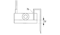
図12Dの態様は、細胞培養容器7に陰圧をかけるための陰圧供給手段71を備えているシステムに適用可能な態様である。本態様は、培地排出手段8の管状部材が細胞培養容器の排出口7bを突き抜けて細胞培養容器の底面から所定の高さ(7f)にまで延びている。このことにより、細胞培養容器内の培地の高さが所定の高さ(7f)以上に達すると、培地排出手段8の管状部材内の陰圧により所定の高さ(7f)を超える培地が細胞培養容器外に排出される。
その後、培地供給手段6から培地が供給され、細胞培養容器内の培地の高さが所定の高さ(7f)に達すると再び排出が起こるという工程を繰り返すことになる。所定の高さ(7f)は培養する細胞の種類や培養条件により設定する。
その後、培地供給手段6から培地が供給され、細胞培養容器内の培地の高さが所定の高さ(7f)に達すると再び排出が起こるという工程を繰り返すことになる。所定の高さ(7f)は培養する細胞の種類や培養条件により設定する。
図12Aから図12Dでは、フラスコ様の細胞培養容器を示したが、図13Aから図13Dに示すようにシャーレ様の細胞培養容器などを用いても良い。図13Aから図13Dにおいて図12Aから図12Dに対応する箇所は同じ番号を付している。
上記各実施形態において、使用する細胞培養容器として図面では、フラスコ様の培養容器を示したが、図13Aから図13Dに示すようにシャーレ様の培養容器などを用いても良い。また、溶液を供給する供給口、溶液を排出する排出口を備えた袋状の細胞培養バッグを用いても良い。さらに、図14Aおよび図14Bに示すように流路を形成するしきいを有した細胞培養容器を用いても良い。当該容器を用い、供給口141と排出口142を流路に沿って離れた位置に設置すれば培地の交換効率が向上する。
上記各実施形態のサイフォン機構を備えた態様において、培地供給手段のサイフォン機構を1つ備えた態様を示したが、図15Aに示すように、サイフォン機構を複数備えていても良い。この場合、各サイフォン機構と一時保持手段4の接続部を重力方向の高さを違えて配置しておくと、重力方向で下のサイフォン機構が機能しなかった場合に重力方向で上のサイフォン機構でバックアップをすることができる。図15Aは第1実施形態に対応する例であるが、他の実施形態も同様である。
上記各実施形態において、図15Bに示すように、一時保持手段4にバックアップ排出口4cを設置しても良い。バックアップ排出口4cを管状部材で培地供給手段6(例えば分岐手段6c)に接続すれば、サイフォン機構6aが機能せずに一時保持手段4内の培地がバックアップ排出口4cまで達した場合に培地を培地供給手段に流出させることができる。バックアップ排出口4cからの管状部材を培地供給手段6ではなく、例えば培地排出手段8につないでも良いし、培地保存手段3につないでも良い。図15Bは第1実施形態に対応する例であるが、他の実施形態も同様である。
上記各実施形態において、培地保存手段3は管状部材(チューブ等)を介して一時保持手段4に連結し、培地保存手段3は一時保持手段4よりも重力方向で上の位置に設置されているため、培地保存手段3内の培地は重力により管状部材(チューブ等)を介して一時保持手段4に供給される態様を示したが、例えば図16に示すように、培地保存手段と一時保持手段をつなぐ管状部材(チューブ等)に供給速度調整手段としてペリスタポンプなどの送液ポンプ5aを設置して、培地保存手段3から一時保持手段4へ培地を供給しても良い。この場合、培地保持手段3は必ずしも一時保持手段4より重力方向で上の位置に設置する必要がなく、培地保持手段3の設置場所の自由度が上がる。この場合、ペリスタポンプなどの送液ポンプ5aは、制御手段により遠隔的に操作されても良い。遠隔的な操作は有線でも無線でも良い。図16は第1実施形態に対応する例であるが、他の実施形態も同様である。
上記各実施形態において、例えば図17に示すように、培地供給手段6が供給速度調整手段5bを備えていても良い。設置場所は分岐手段6cより流路上流に設置することが好ましい。これにより、培養条件により細胞培養容器に供給される培地の供給速度を調整することができ利便性が向上する。供給速度調整手段5bの構成は、培地保存手段3と一時保持手段をつなぐは管状部材(チューブ等)に設置する供給速度調整手段5と同様の構成を有していれば良い。また、供給速度調整手段5と同様、制御手段により有線または無線で遠隔的に操作されても良い。
上記各実施形態においては、培養容器の排出口から排出された廃液は廃液保持手段を介して排出される例を示したが、例えば図18Aに示すように、廃液保持手段を設けず、細胞培養容器の排出口から直接排出されることにしても良い。図18Aは第1実施形態に対応する例であるが、他の実施形態も同様である。
この場合、第3実施形態では細胞培養容器の各排出口に陰圧供給手段の吸引口を接続すれば良い。
この場合、第3実施形態では細胞培養容器の各排出口に陰圧供給手段の吸引口を接続すれば良い。
上記各実施形態において、培地保持手段や一時保持手段をそれぞれ1つずつ備えた態様を示したが、培地保持手段や一時保持手段をそれぞれ複数備えていても良い。この場合、複数種類の培地を細胞培養容器に供給することが可能となる。
上記各実施形態において、1つの培地供給手段から複数の細胞培養容器につながる態様を示したが、1つの培地供給手段から1つの細胞培養容器につながる態様でも良い。
上記各実施形態において、一時保持手段に培地温度をモニタリングする培地温度モニタリング手段を設置しても良い。このとき培地温度モニタリング手段がモニタリングした培地温度の情報を遠隔的に制御部に送るようにしても良い。このことで、細胞培養に適していない温度の培地を誤って供給してしまうことを防ぐことができる。
また、細胞培養容器内に保持する培地の量を可能な限り少量とすることで、培地の交換効率を向上させることができる。細胞培養容器内に保持する培地の量は、培養する細胞の種類により最適化すれば良い。
上記各実施形態において、インキュベータ外に設置された制御部が、上記各実施形態における温度制御手段、圧力付加手段、陰圧供給手段、送液ポンプと無線または有線により情報交換可能して遠隔的にそれらをコントロール可能になっていても良い。このことにより、ユーザによる遠隔作業の効率を上げることができる。
上記各実施形態において、ユーザが制御部により遠隔的に培地交換の操作をする態様については、ユーザがあらかじめ設定したスケジュール(プログラム)に基づき制御部が培地交換を遠隔的に操作しても良い。
上記各実施形態において、一時保持手段がインキュベータ内に設置された態様を示したが、一時保持手段がインキュベータの外に設置されていても良い。その場合、一時保持手段内の溶液を細胞培養に適した温度(例えば37℃)に維持するための温度制御手段を設置することが好ましい。
また、上記各実施形態において、廃液保持手段がインキュベータ外に設置された態様を示したが、例えば図18Bに示すように、廃液保持手段がインキュベータ内に設置されていても良い。
また、上記各実施形態において、廃液保持手段がインキュベータ外に設置された態様を示したが、例えば図18Bに示すように、廃液保持手段がインキュベータ内に設置されていても良い。
本発明の制御部の例としてはPCを挙げることができ、PCが上記各実施形態における制御部が実行する制御を行うことができる。
つまり、制御部は、例えばCPUとメモリを有するPCであり、メモリに記載された制御プログラムをCPUが実行することで制御部としての機能を実現する。
つまり、制御部は、例えばCPUとメモリを有するPCであり、メモリに記載された制御プログラムをCPUが実行することで制御部としての機能を実現する。
本発明において、培地保存手段3内部の培地温度は、培養条件により適当な温度を設定すれば良い。温度制御手段2で37℃に維持しても良い。また、培地保存手段3をインキュベータ内に設置しても良く、その場合培地温度を37℃に維持するのであれば温度制御手段2はなくても良い。
本発明において、培地保存手段、一時培地保持手段は、培地やその他の溶液(例えば洗浄液など)を保持することが可能な手段であり、溶液保持手段として機能するものである。培地保存手段、一時培地保持手段それぞれが溶液保持手段として機能するとともに、両手段が一体として溶液保持手段としても機能する。
本発明により、細胞を培養するための培地を保持する培地保存手段と、
前記培地保存手段と連結し、前記培地保存手段から供給された培地を一時保持するための保持空間と、培地を排出するための排出口を備えた一時保持手段と、
該一時保持手段の前記排出口と連結し、前記一時保持手段から排出された培地を細胞培養容器に供給する培地供給手段と、
前記細胞培養容器から培地を排出する培地排出手段と、
を備えた細胞培養システムであって、
前記培地供給手段は、前記一時保持手段から排出された培地を、所定の周期で断続的に前記細胞培養容器に供給するための培地断続供給機構を備えた細胞培養システムを提供することができる。
前記培地保存手段と連結し、前記培地保存手段から供給された培地を一時保持するための保持空間と、培地を排出するための排出口を備えた一時保持手段と、
該一時保持手段の前記排出口と連結し、前記一時保持手段から排出された培地を細胞培養容器に供給する培地供給手段と、
前記細胞培養容器から培地を排出する培地排出手段と、
を備えた細胞培養システムであって、
前記培地供給手段は、前記一時保持手段から排出された培地を、所定の周期で断続的に前記細胞培養容器に供給するための培地断続供給機構を備えた細胞培養システムを提供することができる。
本発明により、細胞を培養するための培地を保持する培地保存手段と、
前記培地保存手段と連結し、前記培地保存手段から供給された培地を一時保持するための保持空間と、培地を排出するための排出口を備えた一時保持手段と、
該一時保持手段の前記排出口と連結し、前記一時保持手段から排出された培地を細胞培養容器に供給する培地供給手段と、
前記細胞培養容器から培地を排出する培地排出手段と、
を備えた細胞培養システムであって、
前記培地排出手段は、所定の周期で断続的に前記細胞培養容器内部の培地を外部に排出するための培地断続排出機構を備えた細胞培養システムを提供することができる。
前記培地保存手段と連結し、前記培地保存手段から供給された培地を一時保持するための保持空間と、培地を排出するための排出口を備えた一時保持手段と、
該一時保持手段の前記排出口と連結し、前記一時保持手段から排出された培地を細胞培養容器に供給する培地供給手段と、
前記細胞培養容器から培地を排出する培地排出手段と、
を備えた細胞培養システムであって、
前記培地排出手段は、所定の周期で断続的に前記細胞培養容器内部の培地を外部に排出するための培地断続排出機構を備えた細胞培養システムを提供することができる。
上記第1実施形態およびその変形例において、サイフォン機構6aが一時保持手段4の外部に設置された態様を示したが、例えば図19に示すように、一時保持手段4の内部に設置しても良い。この場合、サイフォン機構6aの流路を形成する管状部材は、一時保持手段4の排出口4bから一時保持手段4内部に向けて重力方向で上方に所定の高さまで延び、そこで折り返して重力方向の下方に延びる構造をしている。重力方向の下方に延びた管状部材の端は、一時保持手段4の底面から間隙を開けた近傍に開口部6dを有する構造となっている。ここで、サイフォン機構6aの流路が重力方向で上方に達する所定の高さは、一時保持手段4内に保持される培地が重力方向で達し得る最高の高さより低い位置に設定される(以降この設定高さを「折り返し点6b」という)。
このことにより、一時保持手段4内の培地の高さが折り返し点6bの高さ以上に達すると、サイフォンの原理に従い、一時保持手段4内の培地はサイフォン機構6aの流路を介して排出口4bから排出され始め、一時保持手段4内の培地の高さがサイフォン機構6aの開口部6dに達するまで排出が継続する。その後、培地保存手段3から供給される培地により一時保持手段4内の培地の高さは上昇し始め、サイフォン機構6aの流路の折り返し点6bより高い位置に達すると再び排出が起こるという工程を繰り返す。
つまり、本発明のサイフォン機構6aは、サイフォンの原理により一時保持手段4から細胞培養容器に培地を断続的に供給することができる流路を備えた機構である。
つまり、本発明のサイフォン機構6aは、サイフォンの原理により一時保持手段4から細胞培養容器に培地を断続的に供給することができる流路を備えた機構である。
本発明によれば、培地を供給するための供給口と、培地を排出するための排出口と、該排出口に接続した管状部材(排出サイフォン機構)を備えた細胞培養容器であって、前記管状部材はサイフォンの原理により細胞培養容器内の培地を断続的に排出することができる流路を形成する細胞培養容器を提供することができる。
例えば、図12B、図12C、図13Bおよび図13Cに例示するような細胞培養容器7を提供することができる。つまり、培地を供給するための供給口7aと、培地を排出するための排出口7bと、該排出口7bに接続した管状部材(排出サイフォン機構)を備えた細胞培養容器7であって、排出口7bは、容器底面から所定の高さの位置の容器側面に配置され、管状部材は、排出口7bより重力方向で上の位置かつ容器内の空間の重力方向で最大の高さより低い位置を通過させる流路を形成する細胞培養容器7である。
また、図20Aおよび図20Bに例示するような細胞培養容器7を提供することができる。つまり、培地を供給するための供給口7aと、培地を排出するための排出口7bと、該排出口7bに接続した管状部材(排出サイフォン機構)を備えた細胞培養容器7であって、管状部材は細胞培養容器7内部に設置され、排出口7bより重力方向で上の位置かつ容器内の空間の重力方向で最大の高さより低い位置を通過させる流路を形成し、管状部材の排出口7bに接続した端とは逆の他端は、細胞培養容器7の底面から間隙を開けた近傍に開口部を有する細胞培養容器7である。
これらの細胞培養容器7の内部に培地を供給する培地供給手段6を、細胞培養容器7の供給口に接続して細胞培養システムとすることができる。培地供給手段6としては、例えば図21に示すように、培地保存容器152と供給口151aをチューブ等の管状部材153で接続し、管状部材153に送液ポンプ154を設置した手段でも良い。
また、供給口を細胞培養容器7の上面に配置し、培地供給手段6により供給口から培地上面に培地を滴下しても良い。こうすることで、培地の逆流を防ぐことができ、システム上流に配置されている培地保持容器内の培地が汚染される(コンタミネーションが起こる)ことを防止することができる。
この細胞培養システムによれば、培地供給手段6によって細胞培養容器7内に培地が供給され、細胞培養容器7内の培地が所定量を超えるとサイフォンの原理に基づき、排出サイフォン機構6aが所定の高さまで培地を排出することになり、断続的に古い培地と新しい培地を入れ換えることができる。
上記各実施形態およびその変形例において、サイフォンの原理により培地を断続的に供給、排出する態様を示したが、透析膜等の多孔質膜を用いる細胞培養系においては、透析液等の溶液をサイフォンの原理により断続的に供給、排出しても良い。
この態様における細胞培養容器の一例を図22Aに示す。多孔質膜でできた細胞培養バッグ162内部には培地および細胞が収納されている。細胞培養バッグ162は、透析液等の溶液に漬かった状態で透析容器161内に格納されている。透析容器161は内部に溶液を供給するための供給口161aと外部に溶液を排出するための排出口161bを備えている。透析容器161および細胞培養バッグ162が上記各実施形態およびその変形例における細胞培養容器として機能する。
また、細胞培養容器の他の一例を図22Bに示す。培養容器164内部には培地および細胞が収納されている。多孔質膜でできた透析バッグ163内部には透析液等の溶液が収納され、培地に漬かった状態で培養容器164の内に格納されている。透析バッグ163は内部に溶液を供給するための供給口163aと外部に溶液を排出するための排出口163bを備えている。透析バッグ163および培養容器164が上記各実施形態およびその変形例における細胞培養容器として機能する。
この態様によれば、接着細胞はもちろんのこと浮遊細胞にも適用可能である。
この態様によれば、接着細胞はもちろんのこと浮遊細胞にも適用可能である。
つまり、本発明によれば、
溶液を保持する溶液保存手段と、
該溶液保存手段と連結し、前記溶液保存手段から供給された溶液を一時保持するための保持空間と、溶液を排出するための排出口を備えた一時保持手段と、
該一時保持手段の前記排出口と連結し、前記一時保持手段から排出された溶液を細胞培養容器に供給する溶液供給手段と、
前記細胞培養容器から溶液を排出する排出手段と、
を備えた細胞培養システムであって、
前記細胞培養容器は、前記溶液供給手段より重力方向で下の位置で前記溶液供給手段と連結し、
前記溶液供給手段は、サイフォンの原理により前記一時保持手段から前記細胞培養容器に溶液を断続的に供給することができる流路を備えている細胞培養システムを提供することができる。
また、本発明によれば、
溶液を保持する溶液保存手段と、前記溶液保存手段と連結し、前記溶液保存手段から供給された溶液を一時保持するための保持空間と、溶液を排出するための排出口を備えた一時保持手段と、
該一時保持手段の前記排出口と連結し、前記一時保持手段から排出された溶液を細胞培養容器に供給する溶液供給手段と、
前記細胞培養容器から溶液を排出する排出手段と、
を備えた細胞培養システムであって、
前記細胞培養容器は、前記溶液供給手段より重力方向で下の位置で前記溶液供給手段と連結し、
前記溶液供給手段は、前記保持空間内の培地が所定の量に達した時に流路を開く供給ゲート備えている細胞培養システムを提供することができる。
溶液を保持する溶液保存手段と、前記溶液保存手段と連結し、前記溶液保存手段から供給された溶液を一時保持するための保持空間と、溶液を排出するための排出口を備えた一時保持手段と、
該一時保持手段の前記排出口と連結し、前記一時保持手段から排出された溶液を細胞培養容器に供給する溶液供給手段と、
前記細胞培養容器から溶液を排出する排出手段と、
を備えた細胞培養システムであって、
前記細胞培養容器は、前記溶液供給手段より重力方向で下の位置で前記溶液供給手段と連結し、
前記溶液供給手段は、前記保持空間内の培地が所定の量に達した時に流路を開く供給ゲート備えている細胞培養システムを提供することができる。
1 インキュベータ
2 温度制御手段
3 培地保存手段
4 一時保持手段
4c バックアップ排出口
5 供給速度調整手段
5a 送液ポンプ
5b 供給速度調整手段
6 培地供給手段
6a サイフォン機構
6c 分岐手段
6d 供給ゲート
7 細胞培養容器
8 培地排出手段
8a 廃液保持手段
19 制御部
20 管状部材(チューブ)
21 板状部材
22 球状(円柱状)部材
23、25、26 貫通穴
24 シャッター状部材
31 弁
32 リング部材
33 ボール
34 弾性部材
41 弁
42 フロート
43 リング部材
44 ボール
45 ひも状部材
51 圧力負荷手段
61 袋状部材
62、64 隔離部材
65 重り
71 陰圧供給手段
81 ポンプ
82 廃液容器
83 吸引口
91 培養容器
92 蓋部
95 供給管部
96 排出管部
97 首部
100、200、300、400、500、600、700、800、900、1000、1100、1200 細胞培養システム
101 凸部
102 リング状部材
103 凹部
111 円盤状部材
112 蓋本体
113 リング状部材
Claims (14)
- 細胞を培養するための培地を保持する培地保存手段と、
前記培地保存手段と連結し、前記培地保存手段から供給された培地を一時保持するための保持空間と、培地を排出するための排出口を備えた一時保持手段と、
該一時保持手段の前記排出口と連結し、前記一時保持手段から排出された培地を細胞培養容器に供給する培地供給手段と、
前記細胞培養容器から培地を排出する排出手段と、
を備えた細胞培養システムであって、
前記細胞培養容器は、前記培地供給手段より重力方向で下の位置で前記培地供給手段と連結し、
前記培地供給手段は、サイフォンの原理により前記一時保持手段から前記細胞培養容器に培地を断続的に供給することができる流路を備えている細胞培養システム。 - 細胞を培養するための培地を保持する培地保存手段と、
前記培地保存手段と連結し、前記培地保存手段から供給された培地を一時保持するための保持空間と、培地を排出するための排出口を備えた一時保持手段と、
該一時保持手段の前記排出口と連結し、前記一時保持手段から排出された培地を細胞培養容器に供給する培地供給手段と、
前記細胞培養容器から培地を排出する排出手段と、
を備えた細胞培養システムであって、
前記細胞培養容器は、前記培地供給手段より重力方向で下の位置で前記培地供給手段と連結し、
前記培地供給手段は、前記保持空間内の培地が所定の量に達した時に流路を開く供給ゲート備えている細胞培養システム。 - 前記培地供給手段は、前記細胞培養容器に供給する前の培地を、前記一時保持手段の排出口より重力方向で上の位置かつ前記保持空間の重力方向で最大の高さより低い位置を通過させる流路を備えた請求項1に記載の細胞培養システム。
- 前記排出口は、前記一時保持手段底面から所定の高さの位置の前記一時保持手段側面に配置され、
前記培地供給手段は、前記排出口から前記一時保持手段の外部に流路を形成する請求項3に記載の細胞培養システム。 - 前記培地供給手段は、前記一時保持手段の排出口から前記一時保持手段の内部に流路を形成し、
前記一時保持手段の排出口に接続した前記培地供給手段の端とは逆の端が、前記一時保持手段の底面から間隙を開けた近傍に開口部を有している請求項3に記載の細胞培養システム。 - 前記供給ゲートが、前記保持空間内の培地が所定の重さに達したときに流路を開く請求項2に記載の細胞培養システム。
- 前記供給ゲートが、前記保持空間内の培地上面が所定の高さに達したときに流路を開く請求項2に記載の細胞培養システム。
- 前記細胞培養容器は、内部の培地上面の高さが所定の高さに達したときに培地を外部に排出するための排出口を備えた請求項1から請求項7のいずれかに記載の細胞培養システム。
- 前記培地保存手段から前記一時保持手段に供給される培地の供給速度を制御する供給速度調整手段を備えた請求項1から請求項8のいずれかに記載の細胞培養システム。
- 培地を供給するための供給口と、培地を排出するための排出口と、該排出口に接続した管状部材を備えた細胞培養容器であって、
前記管状部材は、サイフォンの原理により前記細胞培養容器内の培地を断続的に排出することができる流路を形成する細胞培養容器。 - 前記管状部材は、前記排出口より重力方向で上の位置かつ前記細胞培養容器内の空間の重力方向で最大の高さより低い位置を通過する流路を形成する請求項10に記載の細胞培養容器。
- 前記排出口は、前記細胞培養容器の底面から所定の高さの位置の前記細胞培養容器の側面に配置され、
前記管状部材は、前記排出口から前記細胞培養容器の外部に流路を形成する請求項11に記載の細胞培養容器。 - 前記管状部材は、前記排出口から前記細胞培養容器の内部に流路を形成し、
前記管状部材の前記排出口に接続した端とは逆の端が、前記細胞培養容器の前記底面から間隙を開けた近傍に開口部を有している請求項11に記載の細胞培養容器。 - 請求項10から請求項13のいずれかに記載の細胞培養容器と、
該細胞培養容器の前記供給口から内部に培地を供給する培地供給手段とを備えた細胞培養システム。
Priority Applications (4)
| Application Number | Priority Date | Filing Date | Title |
|---|---|---|---|
| JP2016557801A JPWO2016072460A1 (ja) | 2014-11-06 | 2015-11-05 | 細胞培養システムおよび細胞培養容器 |
| EP15857361.8A EP3216857A4 (en) | 2014-11-06 | 2015-11-05 | Cell culture system and cell culture container |
| CN201580059368.8A CN107109336A (zh) | 2014-11-06 | 2015-11-05 | 细胞培养系统以及细胞培养容器 |
| US15/495,435 US20170226465A1 (en) | 2014-11-06 | 2017-04-24 | Cell culture system and cell culture vessel |
Applications Claiming Priority (2)
| Application Number | Priority Date | Filing Date | Title |
|---|---|---|---|
| JP2014-225781 | 2014-11-06 | ||
| JP2014225781 | 2014-11-06 |
Related Child Applications (1)
| Application Number | Title | Priority Date | Filing Date |
|---|---|---|---|
| US15/495,435 Continuation US20170226465A1 (en) | 2014-11-06 | 2017-04-24 | Cell culture system and cell culture vessel |
Publications (1)
| Publication Number | Publication Date |
|---|---|
| WO2016072460A1 true WO2016072460A1 (ja) | 2016-05-12 |
Family
ID=55909184
Family Applications (1)
| Application Number | Title | Priority Date | Filing Date |
|---|---|---|---|
| PCT/JP2015/081200 Ceased WO2016072460A1 (ja) | 2014-11-06 | 2015-11-05 | 細胞培養システムおよび細胞培養容器 |
Country Status (5)
| Country | Link |
|---|---|
| US (1) | US20170226465A1 (ja) |
| EP (1) | EP3216857A4 (ja) |
| JP (1) | JPWO2016072460A1 (ja) |
| CN (1) | CN107109336A (ja) |
| WO (1) | WO2016072460A1 (ja) |
Cited By (4)
| Publication number | Priority date | Publication date | Assignee | Title |
|---|---|---|---|---|
| WO2016157865A1 (ja) * | 2015-03-27 | 2016-10-06 | 川崎重工業株式会社 | 薬液ピペット装置、薬液移送システムおよび薬液移送方法 |
| WO2018186426A1 (ja) * | 2017-04-07 | 2018-10-11 | オリンパス株式会社 | 培地交換装置および培養システム |
| KR102019437B1 (ko) * | 2018-05-21 | 2019-09-09 | 주식회사 다나그린 | 세포 배양액 자동공급시스템 |
| WO2024150585A1 (ja) * | 2023-01-12 | 2024-07-18 | パナソニックIpマネジメント株式会社 | 培養容器及び細胞培養装置 |
Families Citing this family (7)
| Publication number | Priority date | Publication date | Assignee | Title |
|---|---|---|---|---|
| JP7451877B2 (ja) * | 2019-04-27 | 2024-03-19 | 東洋製罐グループホールディングス株式会社 | 細胞培養システム |
| CN112574883B (zh) * | 2020-12-15 | 2022-10-14 | 山东省农业科学院畜牧兽医研究所 | 一种动物肌肉细胞培养用装置 |
| WO2022202731A1 (ja) * | 2021-03-26 | 2022-09-29 | テルモ株式会社 | 細胞培養システム |
| JP7720162B2 (ja) * | 2021-04-27 | 2025-08-07 | 株式会社日立製作所 | 細胞培養システム |
| CN113353307B (zh) * | 2021-06-03 | 2022-08-02 | 北京君立康生物科技有限公司 | 物料分装设备 |
| US12606791B2 (en) | 2023-01-19 | 2026-04-21 | Drsignal Biotechnology Co., Ltd. | Gravitational liquid-splitting device, cell passaging device with the same, and cell passaging method |
| EP4410950B1 (en) * | 2023-02-02 | 2025-05-28 | Drsignal Biotechnology Co., Ltd | Gravitational liquid-splitting device, cell passaging device with the same, and cell passaging method |
Citations (3)
| Publication number | Priority date | Publication date | Assignee | Title |
|---|---|---|---|---|
| JPH06165624A (ja) * | 1992-12-02 | 1994-06-14 | Iwate Pref Gov | 植物体の培養方法及びバイオリアクタ |
| JP2002159241A (ja) * | 2000-11-27 | 2002-06-04 | Central Res Inst Of Electric Power Ind | 魚介類飼育装置 |
| JP2004089137A (ja) * | 2002-09-03 | 2004-03-25 | Olympus Corp | 培養装置および培地交換方法 |
Family Cites Families (6)
| Publication number | Priority date | Publication date | Assignee | Title |
|---|---|---|---|---|
| GB2314343B (en) * | 1996-06-18 | 2000-08-23 | Liau Ming Yi | Method and apparatus for cultivating anchorage dependent monolayer cells |
| CN2582624Y (zh) * | 2002-09-08 | 2003-10-29 | 高建国 | 一次性自动控制输液器 |
| CN2827400Y (zh) * | 2005-09-14 | 2006-10-18 | 王佰河 | 自动报警输液器 |
| CN101457205B (zh) * | 2009-01-08 | 2011-11-16 | 上海交通大学 | 虹吸式间歇喷雾生物反应器 |
| CN102998198B (zh) * | 2012-12-04 | 2014-10-15 | 上海交通大学 | 测定植物离体根比生长速率的装置和方法 |
| CN203820795U (zh) * | 2014-05-05 | 2014-09-10 | 王贺民 | 虹吸式高密度细胞培养瓶 |
-
2015
- 2015-11-05 WO PCT/JP2015/081200 patent/WO2016072460A1/ja not_active Ceased
- 2015-11-05 CN CN201580059368.8A patent/CN107109336A/zh active Pending
- 2015-11-05 EP EP15857361.8A patent/EP3216857A4/en not_active Withdrawn
- 2015-11-05 JP JP2016557801A patent/JPWO2016072460A1/ja active Pending
-
2017
- 2017-04-24 US US15/495,435 patent/US20170226465A1/en not_active Abandoned
Patent Citations (3)
| Publication number | Priority date | Publication date | Assignee | Title |
|---|---|---|---|---|
| JPH06165624A (ja) * | 1992-12-02 | 1994-06-14 | Iwate Pref Gov | 植物体の培養方法及びバイオリアクタ |
| JP2002159241A (ja) * | 2000-11-27 | 2002-06-04 | Central Res Inst Of Electric Power Ind | 魚介類飼育装置 |
| JP2004089137A (ja) * | 2002-09-03 | 2004-03-25 | Olympus Corp | 培養装置および培地交換方法 |
Non-Patent Citations (1)
| Title |
|---|
| See also references of EP3216857A4 * |
Cited By (10)
| Publication number | Priority date | Publication date | Assignee | Title |
|---|---|---|---|---|
| WO2016157865A1 (ja) * | 2015-03-27 | 2016-10-06 | 川崎重工業株式会社 | 薬液ピペット装置、薬液移送システムおよび薬液移送方法 |
| WO2018186426A1 (ja) * | 2017-04-07 | 2018-10-11 | オリンパス株式会社 | 培地交換装置および培養システム |
| KR102019437B1 (ko) * | 2018-05-21 | 2019-09-09 | 주식회사 다나그린 | 세포 배양액 자동공급시스템 |
| WO2019225893A1 (ko) * | 2018-05-21 | 2019-11-28 | 주식회사 다나그린 | 3차원 세포 자동 배양기 |
| JP2021524284A (ja) * | 2018-05-21 | 2021-09-13 | ダナグリーン カンパニー リミテッドDanagreen Co., Ltd. | 3次元自動細胞培養装置 |
| JP7263508B2 (ja) | 2018-05-21 | 2023-04-24 | ダナグリーン カンパニー リミテッド | 3次元自動細胞培養装置 |
| JP2023089137A (ja) * | 2018-05-21 | 2023-06-27 | ダナグリーン カンパニー リミテッド | 3次元自動細胞培養装置 |
| US11884908B2 (en) | 2018-05-21 | 2024-01-30 | Danagreen Co., Ltd. | 3D cell automated incubator |
| JP7573901B2 (ja) | 2018-05-21 | 2024-10-28 | ダナグリーン カンパニー リミテッド | 3次元自動細胞培養装置 |
| WO2024150585A1 (ja) * | 2023-01-12 | 2024-07-18 | パナソニックIpマネジメント株式会社 | 培養容器及び細胞培養装置 |
Also Published As
| Publication number | Publication date |
|---|---|
| JPWO2016072460A1 (ja) | 2017-08-31 |
| EP3216857A1 (en) | 2017-09-13 |
| US20170226465A1 (en) | 2017-08-10 |
| CN107109336A (zh) | 2017-08-29 |
| EP3216857A4 (en) | 2018-08-01 |
Similar Documents
| Publication | Publication Date | Title |
|---|---|---|
| WO2016072460A1 (ja) | 細胞培養システムおよび細胞培養容器 | |
| JP6675309B2 (ja) | 細胞培養システム | |
| US20150017711A1 (en) | Cell culture systems | |
| US11441114B2 (en) | Liquid feed device, and cell culture device and method using same | |
| WO2016027800A1 (ja) | 細胞培養バッグ、細胞培養装置および細胞培養容器 | |
| CN106367342A (zh) | 细胞培养装置 | |
| JP4732187B2 (ja) | 自動培養装置 | |
| EP3039115A1 (en) | Bioreactor with addition tube | |
| JP2015084686A (ja) | 細胞培養用ジグおよび自動培地交換システム | |
| JP2017023131A (ja) | 細胞培養装置 | |
| US20170275579A1 (en) | Cell culture apparatus and cell culture bag | |
| JPWO2015111348A1 (ja) | 細胞培養装置 | |
| TWI756886B (zh) | 細胞培養裝置 | |
| JP6294485B2 (ja) | 送液装置、及び細胞培養装置 | |
| KR102350723B1 (ko) | 자동 배지 교체 시스템 | |
| JPWO2017122658A1 (ja) | 細胞培養容器および容器ホルダ | |
| JP6858653B2 (ja) | 送液装置およびそれを用いた細胞培養装置 | |
| CN102670412A (zh) | 微量补液装置 | |
| AU2014205437B2 (en) | Multiple channel single spike for a liquid dispensing system | |
| JP7237225B1 (ja) | 充填針モジュール及び充填装置 | |
| JP6604467B2 (ja) | 細胞懸濁液の供給装置 | |
| JP2008292186A (ja) | バッチプラントにおける精密計量システム | |
| JP6505942B2 (ja) | 培養容器、培養装置、培養方法 |
Legal Events
| Date | Code | Title | Description |
|---|---|---|---|
| 121 | Ep: the epo has been informed by wipo that ep was designated in this application |
Ref document number: 15857361 Country of ref document: EP Kind code of ref document: A1 |
|
| ENP | Entry into the national phase |
Ref document number: 2016557801 Country of ref document: JP Kind code of ref document: A |
|
| NENP | Non-entry into the national phase |
Ref country code: DE |
|
| REEP | Request for entry into the european phase |
Ref document number: 2015857361 Country of ref document: EP |