WO2016076190A1 - 除害装置 - Google Patents
除害装置 Download PDFInfo
- Publication number
- WO2016076190A1 WO2016076190A1 PCT/JP2015/081146 JP2015081146W WO2016076190A1 WO 2016076190 A1 WO2016076190 A1 WO 2016076190A1 JP 2015081146 W JP2015081146 W JP 2015081146W WO 2016076190 A1 WO2016076190 A1 WO 2016076190A1
- Authority
- WO
- WIPO (PCT)
- Prior art keywords
- circulating water
- flow rate
- concentration
- hydrogen fluoride
- water
- Prior art date
- Legal status (The legal status is an assumption and is not a legal conclusion. Google has not performed a legal analysis and makes no representation as to the accuracy of the status listed.)
- Ceased
Links
Images

Classifications
-
- B—PERFORMING OPERATIONS; TRANSPORTING
- B01—PHYSICAL OR CHEMICAL PROCESSES OR APPARATUS IN GENERAL
- B01D—SEPARATION
- B01D53/00—Separation of gases or vapours; Recovering vapours of volatile solvents from gases; Chemical or biological purification of waste gases, e.g. engine exhaust gases, smoke, fumes, flue gases, aerosols
- B01D53/34—Chemical or biological purification of waste gases
- B01D53/96—Regeneration, reactivation or recycling of reactants
-
- B—PERFORMING OPERATIONS; TRANSPORTING
- B01—PHYSICAL OR CHEMICAL PROCESSES OR APPARATUS IN GENERAL
- B01D—SEPARATION
- B01D21/00—Separation of suspended solid particles from liquids by sedimentation
- B01D21/26—Separation of sediment aided by centrifugal force or centripetal force
-
- B—PERFORMING OPERATIONS; TRANSPORTING
- B01—PHYSICAL OR CHEMICAL PROCESSES OR APPARATUS IN GENERAL
- B01D—SEPARATION
- B01D21/00—Separation of suspended solid particles from liquids by sedimentation
- B01D21/26—Separation of sediment aided by centrifugal force or centripetal force
- B01D21/267—Separation of sediment aided by centrifugal force or centripetal force by using a cyclone
-
- B—PERFORMING OPERATIONS; TRANSPORTING
- B01—PHYSICAL OR CHEMICAL PROCESSES OR APPARATUS IN GENERAL
- B01D—SEPARATION
- B01D47/00—Separating dispersed particles from gases, air or vapours by liquid as separating agent
- B01D47/14—Packed scrubbers
-
- B—PERFORMING OPERATIONS; TRANSPORTING
- B01—PHYSICAL OR CHEMICAL PROCESSES OR APPARATUS IN GENERAL
- B01D—SEPARATION
- B01D53/00—Separation of gases or vapours; Recovering vapours of volatile solvents from gases; Chemical or biological purification of waste gases, e.g. engine exhaust gases, smoke, fumes, flue gases, aerosols
- B01D53/34—Chemical or biological purification of waste gases
- B01D53/38—Removing components of undefined structure
- B01D53/40—Acidic components
-
- B—PERFORMING OPERATIONS; TRANSPORTING
- B01—PHYSICAL OR CHEMICAL PROCESSES OR APPARATUS IN GENERAL
- B01D—SEPARATION
- B01D53/00—Separation of gases or vapours; Recovering vapours of volatile solvents from gases; Chemical or biological purification of waste gases, e.g. engine exhaust gases, smoke, fumes, flue gases, aerosols
- B01D53/34—Chemical or biological purification of waste gases
- B01D53/46—Removing components of defined structure
- B01D53/68—Halogens or halogen compounds
-
- B—PERFORMING OPERATIONS; TRANSPORTING
- B01—PHYSICAL OR CHEMICAL PROCESSES OR APPARATUS IN GENERAL
- B01D—SEPARATION
- B01D53/00—Separation of gases or vapours; Recovering vapours of volatile solvents from gases; Chemical or biological purification of waste gases, e.g. engine exhaust gases, smoke, fumes, flue gases, aerosols
- B01D53/34—Chemical or biological purification of waste gases
- B01D53/74—General processes for purification of waste gases; Apparatus or devices specially adapted therefor
- B01D53/77—Liquid phase processes
- B01D53/78—Liquid phase processes with gas-liquid contact
-
- C—CHEMISTRY; METALLURGY
- C23—COATING METALLIC MATERIAL; COATING MATERIAL WITH METALLIC MATERIAL; CHEMICAL SURFACE TREATMENT; DIFFUSION TREATMENT OF METALLIC MATERIAL; COATING BY VACUUM EVAPORATION, BY SPUTTERING, BY ION IMPLANTATION OR BY CHEMICAL VAPOUR DEPOSITION, IN GENERAL; INHIBITING CORROSION OF METALLIC MATERIAL OR INCRUSTATION IN GENERAL
- C23C—COATING METALLIC MATERIAL; COATING MATERIAL WITH METALLIC MATERIAL; SURFACE TREATMENT OF METALLIC MATERIAL BY DIFFUSION INTO THE SURFACE, BY CHEMICAL CONVERSION OR SUBSTITUTION; COATING BY VACUUM EVAPORATION, BY SPUTTERING, BY ION IMPLANTATION OR BY CHEMICAL VAPOUR DEPOSITION, IN GENERAL
- C23C16/00—Chemical coating by decomposition of gaseous compounds, without leaving reaction products of surface material in the coating, i.e. chemical vapour deposition [CVD] processes
- C23C16/44—Chemical coating by decomposition of gaseous compounds, without leaving reaction products of surface material in the coating, i.e. chemical vapour deposition [CVD] processes characterised by the method of coating
- C23C16/4412—Details relating to the exhausts, e.g. pumps, filters, scrubbers, particle traps
-
- C—CHEMISTRY; METALLURGY
- C23—COATING METALLIC MATERIAL; COATING MATERIAL WITH METALLIC MATERIAL; CHEMICAL SURFACE TREATMENT; DIFFUSION TREATMENT OF METALLIC MATERIAL; COATING BY VACUUM EVAPORATION, BY SPUTTERING, BY ION IMPLANTATION OR BY CHEMICAL VAPOUR DEPOSITION, IN GENERAL; INHIBITING CORROSION OF METALLIC MATERIAL OR INCRUSTATION IN GENERAL
- C23C—COATING METALLIC MATERIAL; COATING MATERIAL WITH METALLIC MATERIAL; SURFACE TREATMENT OF METALLIC MATERIAL BY DIFFUSION INTO THE SURFACE, BY CHEMICAL CONVERSION OR SUBSTITUTION; COATING BY VACUUM EVAPORATION, BY SPUTTERING, BY ION IMPLANTATION OR BY CHEMICAL VAPOUR DEPOSITION, IN GENERAL
- C23C16/00—Chemical coating by decomposition of gaseous compounds, without leaving reaction products of surface material in the coating, i.e. chemical vapour deposition [CVD] processes
- C23C16/44—Chemical coating by decomposition of gaseous compounds, without leaving reaction products of surface material in the coating, i.e. chemical vapour deposition [CVD] processes characterised by the method of coating
- C23C16/52—Controlling or regulating the coating process
-
- H—ELECTRICITY
- H10—SEMICONDUCTOR DEVICES; ELECTRIC SOLID-STATE DEVICES NOT OTHERWISE PROVIDED FOR
- H10P—GENERIC PROCESSES OR APPARATUS FOR THE MANUFACTURE OR TREATMENT OF DEVICES COVERED BY CLASS H10
- H10P14/00—Formation of materials, e.g. in the shape of layers or pillars
- H10P14/60—Formation of materials, e.g. in the shape of layers or pillars of insulating materials
-
- B—PERFORMING OPERATIONS; TRANSPORTING
- B01—PHYSICAL OR CHEMICAL PROCESSES OR APPARATUS IN GENERAL
- B01D—SEPARATION
- B01D2252/00—Absorbents, i.e. solvents and liquid materials for gas absorption
- B01D2252/10—Inorganic absorbents
- B01D2252/103—Water
-
- B—PERFORMING OPERATIONS; TRANSPORTING
- B01—PHYSICAL OR CHEMICAL PROCESSES OR APPARATUS IN GENERAL
- B01D—SEPARATION
- B01D2257/00—Components to be removed
- B01D2257/20—Halogens or halogen compounds
- B01D2257/204—Inorganic halogen compounds
- B01D2257/2047—Hydrofluoric acid
-
- B—PERFORMING OPERATIONS; TRANSPORTING
- B01—PHYSICAL OR CHEMICAL PROCESSES OR APPARATUS IN GENERAL
- B01D—SEPARATION
- B01D2257/00—Components to be removed
- B01D2257/55—Compounds of silicon, phosphorus, germanium or arsenic
- B01D2257/553—Compounds comprising hydrogen, e.g. silanes
-
- B—PERFORMING OPERATIONS; TRANSPORTING
- B01—PHYSICAL OR CHEMICAL PROCESSES OR APPARATUS IN GENERAL
- B01D—SEPARATION
- B01D2258/00—Sources of waste gases
- B01D2258/02—Other waste gases
- B01D2258/0216—Other waste gases from CVD treatment or semi-conductor manufacturing
-
- B—PERFORMING OPERATIONS; TRANSPORTING
- B01—PHYSICAL OR CHEMICAL PROCESSES OR APPARATUS IN GENERAL
- B01D—SEPARATION
- B01D53/00—Separation of gases or vapours; Recovering vapours of volatile solvents from gases; Chemical or biological purification of waste gases, e.g. engine exhaust gases, smoke, fumes, flue gases, aerosols
- B01D53/34—Chemical or biological purification of waste gases
- B01D53/346—Controlling the process
-
- Y—GENERAL TAGGING OF NEW TECHNOLOGICAL DEVELOPMENTS; GENERAL TAGGING OF CROSS-SECTIONAL TECHNOLOGIES SPANNING OVER SEVERAL SECTIONS OF THE IPC; TECHNICAL SUBJECTS COVERED BY FORMER USPC CROSS-REFERENCE ART COLLECTIONS [XRACs] AND DIGESTS
- Y02—TECHNOLOGIES OR APPLICATIONS FOR MITIGATION OR ADAPTATION AGAINST CLIMATE CHANGE
- Y02C—CAPTURE, STORAGE, SEQUESTRATION OR DISPOSAL OF GREENHOUSE GASES [GHG]
- Y02C20/00—Capture or disposal of greenhouse gases
- Y02C20/30—Capture or disposal of greenhouse gases of perfluorocarbons [PFC], hydrofluorocarbons [HFC] or sulfur hexafluoride [SF6]
-
- Y—GENERAL TAGGING OF NEW TECHNOLOGICAL DEVELOPMENTS; GENERAL TAGGING OF CROSS-SECTIONAL TECHNOLOGIES SPANNING OVER SEVERAL SECTIONS OF THE IPC; TECHNICAL SUBJECTS COVERED BY FORMER USPC CROSS-REFERENCE ART COLLECTIONS [XRACs] AND DIGESTS
- Y02—TECHNOLOGIES OR APPLICATIONS FOR MITIGATION OR ADAPTATION AGAINST CLIMATE CHANGE
- Y02P—CLIMATE CHANGE MITIGATION TECHNOLOGIES IN THE PRODUCTION OR PROCESSING OF GOODS
- Y02P70/00—Climate change mitigation technologies in the production process for final industrial or consumer products
- Y02P70/50—Manufacturing or production processes characterised by the final manufactured product
Definitions
- the present invention relates to an abatement apparatus, and more particularly to an abatement apparatus for treating a process gas containing silicon and a cleaning gas containing fluorine.
- Semiconductor manufacturing equipment, liquid crystal panel manufacturing equipment, solar cell manufacturing equipment, etc. use process gas containing silicon (Si) and cleaning gas containing fluorine (F).
- process gas containing silicon (Si) and cleaning gas containing fluorine (F) For example, in a semiconductor manufacturing process, an insulator, a metal film, or the like is deposited on a semiconductor wafer, and a CVD (Chemical Vapor Deposition) process is performed to form a film using a chemical vapor reaction.
- a process gas such as monosilane (SiH 4) is introduced.
- a cleaning gas such as nitrogen trifluoride (NF3) corresponding to the type of the product is periodically introduced into the process chamber to decompose the adhering matter.
- NF3 nitrogen trifluoride
- the process gas and the cleaning gas discharged from the process chamber are introduced into the abatement apparatus, and the abatement apparatus performs the abatement process to make it harmless.
- a detoxifying device one having an acid removal unit that reduces the acidity of the circulating water of the gas scrubbing unit and a filter unit that captures solid particles in the circulating water is known (for example, Patent Document 1).
- This invention was made in view of such a conventional subject, and it aims at providing the abatement apparatus which reduces the drainage amount of circulating water.
- the present invention has been proposed to achieve the above object, and the invention according to claim 1 is an abatement apparatus for treating exhaust gas containing silicon and exhaust gas containing fluorine, which contains the silicon.
- a drain tank that contains circulating water that dissolves silicon dioxide generated from the exhaust gas and hydrogen fluoride generated from the exhaust gas containing fluorine, a circulation path that communicates with the drain tank, and a circulation path provided in the circulation path
- a drain valve for draining a part of the circulating water to the outside; a makeup water supply means for supplying makeup water to the circulation path; and controlling the drain valve and the makeup water supply means to control the inside of the circulation path.
- Control means for controlling an average drainage flow rate of the circulating water, wherein the control means has a ratio between the concentration of the silicon dioxide in the circulating water and the concentration of the hydrogen fluoride in the circulating water.
- the hydrofluoric acid is not less than a predetermined value capable of generating hydrofluoric acid
- the average drainage flow rate of the circulating water is lowered to a low flow rate, the concentration of the silicon dioxide in the circulating water and the concentration of the hydrogen fluoride in the circulating water
- a detoxifying device that raises the average drainage flow rate of the circulating water to a higher flow rate than the low flow rate.
- the “average drainage flow rate” means an average drainage amount per unit time when circulating water is discharged to the outside.
- the average drainage flow rate of circulating water is lowered to a low flow rate while suppressing the volatilization of fluorine hydrogen in the circulating water. Therefore, the average drainage flow rate of circulating water can be reduced.
- control means includes an integrated flow rate of the exhaust gas containing silicon, the average drainage flow rate of the circulating water, and the flow rate of the makeup water.
- a detoxifying device for deriving the concentration of silicon dioxide based on the above is provided.
- the process gas is removed when the process chamber is cleaned. Even when it does not flow into the inside, the average drainage flow rate of the circulating water can be reduced.
- control means includes the integrated flow rate of the exhaust gas containing fluorine, the average drainage flow rate of the circulating water, and the makeup water.
- a detoxifying device for deriving the concentration of the hydrogen fluoride based on the flow rate is provided.
- the cleaning gas since it is possible to determine whether or not hydrofluoric acid can be generated based on the concentration of hydrogen fluoride remaining in the abatement apparatus, the cleaning gas does not flow into the abatement apparatus during CVD processing or the like. Even in this case, the average drainage flow rate of the circulating water can be reduced.
- the invention described in claim 4 provides a detoxifying device provided with an acidity measuring means for measuring the acidity of the circulating water in addition to the configuration of the invention described in any one of claims 1 to 3. .
- a detoxifying device in addition to the configuration of the fourth aspect of the present invention, there is provided a detoxifying device in which the acidity is derived based on a concentration of hydrogen fluoride in the circulating water measured by a conductivity sensor. To do.
- the abatement device by deriving the acidity of the circulating water based on the hydrogen fluoride concentration measured by the conductivity sensor, the abatement device can be operated for a long period of time with low cost and easy maintenance.
- a sixth aspect of the present invention provides a detoxification apparatus comprising a centrifuge for separating the silicon dioxide from the circulating water in addition to the configuration of the first aspect of the present invention.
- the volatilization of fluorine hydrogen in the circulating water is suppressed even when the average drainage flow rate of the circulating water is lowered to a low flow rate. Therefore, the average drainage flow rate can be reduced.
- the block diagram which shows the connection relation of a process chamber, a dry pump, and an abatement apparatus.
- the schematic diagram which shows the abatement apparatus which concerns on one Example of this invention.
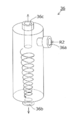
- the perspective view which shows a centrifuge.
- the present invention is an abatement apparatus for treating exhaust gas containing silicon and exhaust gas containing fluorine, wherein the exhaust gas contains silicon.
- a drain tank containing circulating water for dissolving hydrogen fluoride generated from exhaust gas containing silicon dioxide and fluorine generated from gas, a circulating path communicating with the drain tank, and circulating water provided in the circulating path.
- the drainage valve that drains a part of the water to the outside, the supplementary water supply means that supplies makeup water to the circulation path, the drain valve and the supplementary water supply means, and controls the average drainage flow rate of the circulating water in the circulation path Control means, and the control means circulates when the ratio of the concentration of silicon dioxide in the circulating water and the concentration of hydrogen fluoride in the circulating water is greater than or equal to a predetermined value capable of producing hydrofluoric acid.
- the average drainage flow rate of the circulating water is set to a higher flow rate that is greater than the low flow rate. Realized by raising.
- FIG. 1 is a diagram showing a connection relationship between the process chamber 10, the dry pump 20, and the abatement apparatus 30.
- the process chamber 10 is a part of a semiconductor manufacturing apparatus (not shown).
- a device is obtained by performing a CVD process for depositing a thin film on the surface of a semiconductor wafer (not shown) disposed in the process chamber 10.
- one process chamber is connected to one abatement apparatus, but a plurality of process chambers may be connected to one abatement apparatus.
- a process gas G1 containing silicon is supplied in the process chamber 10.
- the process gas G1 is supplied as a reactant for the CVD process in the process chamber 10.
- Part of the process gas G ⁇ b> 1 supplied to the process chamber 10 is consumed during the CVD process, and the other is sucked into the dry pump 20.
- a cleaning gas G2 containing fluorine is supplied into the process chamber 10.
- the cleaning gas G2 volatilizes the residue of the CVD process by performing plasma etching while being filled in the process chamber 10.
- a part of the cleaning gas G ⁇ b> 2 supplied to the process chamber 10 is consumed during the cleaning process, and the other is sucked into the dry pump 20.
- the mass flow controller 11a measures the flow rate of the process gas G1 and sends it to the control means 31.
- the mass flow controller 11b measures the flow rate of the cleaning gas G2 and sends it to the control means 31.
- the flow rates of the process gas G1 and the cleaning gas G2 may be calculated based on the processing conditions of the semiconductor manufacturing apparatus.
- the process chamber 10 and the abatement apparatus 30 are connected via a dry pump 20.
- the dry pump 20 sucks the process gas G1 and the cleaning gas G2 remaining in the process chamber 10 and introduces them into the abatement apparatus 30.
- the abatement device 30 converts the process gas G1 and the cleaning gas G2 introduced from the dry pump 20 into granular silicon dioxide (SiO2) and hydrogen fluoride (HF) gas G3, and then separates them from the exhaust gas and circulates them. It is taken into water R2 and discharged into acid drainage R1 to make it harmless. Specifically, the concentration of hydrogen fluoride contained in the exhaust gas is reduced to a predetermined value (for example, 3 ppm) or less. Further, the acid waste water R1 in which hydrogen fluoride gas is dissolved is drained.
- the shape of silicon dioxide is not limited to granular form, For example, you may be a paste form.
- the control means 31 adjusts the flow rates of the process gas G1 and the cleaning gas G2 sent from the mass flow controllers 11a and 11b, the average drainage flow rate of the hydrogen fluoride gas G3 and the acid wastewater R1 sent from the flow meter 32a, and the flow rate of makeup water described later. Based on this, the average drainage flow rate of the circulating water of the abatement apparatus 30 is controlled.
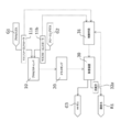
- FIG. 2 is a schematic view showing the abatement apparatus.
- FIG. 3 is a perspective view showing the centrifuge.
- the abatement apparatus 30 includes a heating means 33, a drain tank 34, and a packed tower 35.
- the process gas G1 and the cleaning gas G2 introduced into the abatement apparatus 30 flow in the order of the heating means 33, the drain tank 34, and the packed tower 35, and are exhausted to the outside from the exhaust port 30a.
- the heating means 33 heats the process gas G1 and the cleaning gas G2 to a high temperature.
- the temperature in the heating means 33 is set to 600 to 800 ° C., for example.
- a gas burner is employed as the heating means 33.
- the heating means 33 may have any configuration as long as the process gas G1 and the cleaning gas G2 can be heated, and may be a heater method that heats by the radiant heat of an electric heater, a plasma method that heats by plasma, or the like.
- the drain tank 34 is disposed below the heating means 33 and contains a predetermined amount of circulating water R2.
- the drain tank 34 is made of a corrosion-resistant plastic such as polypropylene, and the temperature of the circulating water R2 is preferably maintained at 60 degrees or less.
- the packed tower 35 is provided above the drain tank 34.
- the packed tower 35 is filled with plastic fine particles (not shown), and water is sprinkled from the water nozzle 35 a installed above the packed tower 35 toward the fine particles.
- the water-soluble hydrogen fluoride gas dissolves in the water on the surface of the microparticles and drops together with the water into the drain tank 34.
- the drain tank 34 communicates with the circulation path r, and the circulating water R2 in the drain tank 34 circulates in the circulation path r.
- the upstream end of the circulation path r is connected to the drain tank 34.
- the circulation path r branches at the centrifuge 36, one being connected to the heat exchanger 37 and the other being connected to the drain tank 34.
- symbol P is a booster pump.
- a centrifuge 36 for separating granular silicon dioxide in the circulating water R2 is provided in the circulation path r. As shown in FIG. 3, the centrifugal separator 36 centrifuges the circulating water R2 flowing in from the inlet 36a as indicated by an arrow, thereby discharging granular silicon dioxide from the lower outlet 36b. Circulating water R2 not included is drained from the upper drainage port 36c.
- the heat exchanger 37 cools the temperature of the circulating water R2, and maintains the water temperature of the circulating water R2 at a predetermined value (for example, 60 degrees) or less.
- the circulating water R2 cooled by the heat exchanger 37 is returned to the drain tank 34.
- a conductivity sensor 38 is provided as acidity measuring means.
- the acidity measuring means employs the transmission rate sensor 38 which is inexpensive and easy to maintain, but may be a pH meter or the like capable of measuring the acidity more accurately.
- Supply water supply means 39 supplies supply water (pure water) to the packed tower 35.
- a water level detection means (not shown) installed in the drain tank 34 sends the water level of the circulating water R2 in the drain tank 34 to the control means 31, and when the water level of the circulating water R2 is below a predetermined value, the control means 31 Make-up water is supplied to the make-up water supply means 39. Further, the control means 31 opens the third valve v3 and closes the fourth valve v4, so that makeup water is supplied into the packed tower 35.
- the supply amount of makeup water is controlled so that the concentration of the hydrogen fluoride gas G3 is a predetermined value or less.
- symbol 39a is a flowmeter which measures the flow volume of makeup water.
- the control means 31 controls the first valve v1, the second valve v2, and the third valve.
- the valve v3 and the fourth valve v4 are opened and closed. Specifically, when the acidity of the circulating water R2 rises above the threshold, the first valve v1 and the third valve v3 are opened, the acid drainage R1 is discharged, and the circulating water R2 is diluted with water. Decrease the degree.
- the second valve v3 and the fourth valve v4 are opened, and the circulating water R2 is circulated in the circulation path r.
- the drain valve v1 can adjust the average drain flow rate of the circulating water R2 by controlling the opening and closing time.
- the process gas G1 is used as the process gas G1
- nitrogen trifluoride (NF3) is used as the cleaning gas G2.
- the process gas G1 is not limited to monosilane
- the cleaning gas G2 is It is not limited to hydrogen trifluoride.
- the ratio of the silicon dioxide present in the drain tank 34 and the silicon dioxide exhausted to the outside varies depending on the type of the abatement apparatus 30 and the like, for example, the former is 60% and the latter is 40%.
- the hydrogen fluoride that has flowed into the packed tower 35 via the drain tank 34 is dissolved in water and dropped into the drain tank 34 when passing through the packed tower 35, and is thus exhausted to the outside through the exhaust port 30 a.
- the hydrogen fluoride concentration is slight (for example, 3 ppm or less).
- the corrosion resistance of the abatement apparatus 30 becomes a problem.
- stainless steel SUS316 grade
- the hydrogen fluoride concentration should be 0.5% or less. Preferably it is managed.
- the average drainage flow rate increases, and as a result, the running cost of the abatement apparatus 30 increases.
- the conductivity sensor 38 measures the conductivity of the circulating water R2, and if the acidity is equal to or higher than a predetermined threshold, the first valve v1 and the third valve v3 are opened to increase the flow rate of the acid drainage R1. At the same time, the supply amount of makeup water is increased, and the acidity of the circulating water R2 is lowered.
- the acidity threshold value can be arbitrarily set, and may be set to 0.5%, for example.
- the threshold value is set to 0.5% and only hydrogen fluoride is present in the circulating water R2, that is, when silicon dioxide is not present in the circulating water R2, the fluorine in the circulating water R2 is present.
- the threshold value is set to 0.5% and only hydrogen fluoride is present in the circulating water R2 that is, when silicon dioxide is not present in the circulating water R2, the fluorine in the circulating water R2 is present.
- hydrogen fluoride will re-volatilize and the hydrogen fluoride concentration of the exhausted hydrogen fluoride gas will increase.
- the detoxification device 30 into which monosilane and nitrogen trifluoride are introduced has a granular dioxide dioxide present in the circulating water R2 circulating in the drain tank 34 and the circulation path r. Silicon and hydrogen fluoride dissolved in circulating water R2 are present. Then, silicon dioxide and hydrogen fluoride generate hydrosilicofluoric acid based on the reaction formula of Formula 3.
- the hydrosilicofluoric acid produced based on the reaction formula of Formula 3 shows acidity similar to hydrogen fluoride when dissolved in the circulating water R2, that is, increases the conductivity of the circulating water R2, but the hydrogen fluoride There is no risk of re-evaporation. Accordingly, the acidity R2 of the circulating water R2 is managed below the threshold value by using the conductivity sensor 38 described above to ensure the reliability of the abatement apparatus 30, and hydrogen fluoride is reduced and hydrosilicic acid is generated. By doing so, an increase in acidity due to hydrogen fluoride as described above is suppressed, so that the flow rate of the acid waste water can be reduced.
- the molar ratio of silicon dioxide and hydrogen fluoride required for the production of hydrosilicofluoric acid is 1: 6.
- silicon dioxide / hydrogen fluoride molar ratio in circulating water R2 is greater than 1/6, that is, about 0.17, hydrogen fluoride reacts with silicon dioxide to produce hydrofluoric acid. The reaction in which is produced occurs.
- the control means 31 calculates the concentration of silicon dioxide in the circulating water R2 based on the flow rate of the process gas G1 and the average drainage flow rate of the circulating water R2. Part of the silicon dioxide remains in the abatement apparatus 30, and the other is discharged to the outside. A part of the silicon dioxide remaining in the abatement apparatus 30 is accommodated in the circulating water R2, and the other is accommodated in the abatement apparatus 30. Therefore, the circulating water R2 is obtained by multiplying the number of moles of silicon dioxide, that is, the number of moles of monosilane in the process gas G1, by the ratio of silicon dioxide accommodated in the abatement apparatus 30 and the ratio accommodated in the circulating water R2. Calculate the concentration of silicon dioxide in it. For example, the former value is 60% and the latter value is 75%. In this case, the number of moles of silicon dioxide in the circulating water R2 is multiplied by 0.6 and 0.75, 0.45 times the number of moles of monosilane.
- the silicon dioxide concentration in the circulating water R2 is calculated based on the integrated flow rate of the process gas G1, the makeup water flow rate, and the average drainage flow rate of the circulating water R2.
- control means 31 calculates the concentration of hydrogen fluoride in the circulating water R2 based on the flow rate of the cleaning gas G2, the makeup water flow rate, and the average drainage flow rate of the circulating water R2. Almost all of the hydrogen fluoride is dissolved in the circulating water R2. Therefore, the number of moles of hydrogen fluoride is three times the number of moles of nitrogen trifluoride.
- the concentration of hydrogen fluoride is calculated based on the integrated flow rate of the cleaning gas G2.
- the concentration of silicon dioxide and the concentration of hydrogen fluoride in the circulating water R2 are calculated, and when the ratio between the concentration of silicon dioxide and the concentration of hydrogen fluoride is not less than a predetermined value, that is, about 0.17.
- a predetermined value for example, 10 lL / min.
- the average drainage flow rate of the circulating water R2 is lowered to a low flow rate (for example, 10 lL / min).
- the ratio of the concentration of silicon dioxide to the concentration of hydrogen fluoride is less than a predetermined value, that is, less than about 0.17, in order to suppress the re-volatilization of hydrogen fluoride,
- the average drainage flow rate is increased to a high flow rate (for example, 20 L / min). If the silicon dioxide concentration and the hydrogen fluoride concentration in the circulating water R2 are sufficiently low, the average drainage flow rate of the circulating water R2 can be made zero.
- the flow rate per unit time of the process gas G1 is set to 20 slm
- the flow rate per unit time of the cleaning gas G2 is set to 50 slm.
- the average drainage flow rate and the makeup water flow rate of the circulating water R2 are zero, and the drain tank 34 and the circulation path r
- the flow rate of the circulating water R2 that circulates is set to 80 L / min as a flow rate necessary for the detoxification process of the detoxification device 30.
- the return amount of the circulating water R2 circulated via the heat exchanger 37 is set to 70 L / min, the second valve v2 is opened, and the return to the drain tank 34 is performed.
- Set volume to 10 L / min.
- the drainage valve v1 In the low flow rate mode (when the acidity of the circulating water R2 is equal to or less than the threshold value and satisfies the conditions for generating hydrofluoric acid), the drainage valve v1 is opened and the circulating water R2 is drained as the acid drainage R1.
- the drainage flow rate when the drainage valve v1 is opened is set to 30 L / min, and the average drainage flow rate of the circulating water R2 is controlled to 10 L / min by opening / closing control of the drainage valve v1. Accordingly, the flow rate of the circulating water R2 in the drain tank 34 and the circulation path r is set to 80 L / min to 100 L / min.
- the minimum flow rate of the circulating water R2 is when the drain valve v1 is closed, and the return amount (70 L / min) of the circulating water R2 circulated via the heat exchanger 37 and the drain tank 34 Is set to 80 L / min which is the sum of the return amount (10 L / min).
- the maximum flow rate of the circulating water R2 is when the drain valve v1 is open, and the return amount (70 L / min) of the circulating water R2 circulated via the heat exchanger 37 and the drain valve v1. It is set to 100 L / min, which is the sum of the drainage flow rate (30 L / min) drained to the outside.
- the flow rate of makeup water when the third valve v3 is opened is set to 20 L / min, and the average flow rate of makeup water is controlled to 10 L / min by opening / closing control of the third valve v3.
- the drain valve v1 In the high flow rate mode (when the acidity of the circulating water R2 is equal to or higher than the threshold value or when the conditions for generating silicofluoric acid are not satisfied), the drain valve v1 is opened and the circulating water R2 is drained as the acid drainage R1.
- the average drainage flow rate of the circulating water R2 is controlled to 20 L / min by opening / closing control of the drainage valve v1. Accordingly, the flow rate of the circulating water R2 in the drain tank 34 and the circulation path r is set to 80 L / min to 100 L / min, as in the low flow rate mode.
- the third valve v3 In the high flow rate mode, the third valve v3 is always open, and the flow rate of makeup water is constant at 20 L / min.
- the abatement apparatus can circulate water R2 even when the average drainage flow rate of circulating water R2 is lowered to a low flow rate when hydrosilicic acid can be generated with silicon dioxide and hydrogen fluoride. Since volatilization of fluorine hydrogen in the inside is suppressed, the acid drainage flow rate can be reduced. Furthermore, it is possible to suppress clogging of granular silicon dioxide in equipment downstream of the centrifuge 36 provided in the circulation path r. can do.
- the present invention can be applied to a liquid crystal panel manufacturing apparatus, a solar cell manufacturing apparatus and the like in addition to a semiconductor manufacturing apparatus.
Landscapes
- Chemical & Material Sciences (AREA)
- Engineering & Computer Science (AREA)
- Chemical Kinetics & Catalysis (AREA)
- General Chemical & Material Sciences (AREA)
- Environmental & Geological Engineering (AREA)
- Oil, Petroleum & Natural Gas (AREA)
- Analytical Chemistry (AREA)
- Biomedical Technology (AREA)
- Health & Medical Sciences (AREA)
- Organic Chemistry (AREA)
- Mechanical Engineering (AREA)
- Metallurgy (AREA)
- Materials Engineering (AREA)
- Life Sciences & Earth Sciences (AREA)
- Sustainable Development (AREA)
- Treating Waste Gases (AREA)
- Gas Separation By Absorption (AREA)
- Cleaning Or Drying Semiconductors (AREA)
- Drying Of Semiconductors (AREA)
Abstract
Description
プロセスチャンバ10は、図示しない半導体製造装置の一部である。プロセスチャンバ10内に配置された図示しない半導体ウェーハの表面に薄膜を被着させるCVD処理を施すことにより、デバイスを得る。なお、図1では、除害装置1台に対してプロセスチャンバ1台が接続されているが、除害装置1台に複数のプロセスチャンバが接続されても構わない。



することができる。
20・・・ ドライポンプ
30・・・ 除害装置
31・・・ 制御装置
32a・・・流量計
33・・・ 加熱手段
34・・・ ドレインタンク
35・・・ パックドタワー
36・・・ 遠心分離器
37・・・ 熱交換器
38・・・ 伝導率センサ(酸性度計測手段)
39・・・ 補給水供給手段
G1・・・ プロセスガス
G2・・・ クリーニングガス
G3・・・ フッ化水素ガス
R1・・・ 酸排水
R2・・・ 循環水
r ・・・ 循環経路
v1・・・ 第1の弁(排水弁)
v2・・・ 第2の弁
v3・・・ 第3の弁
v4・・・ 第4の弁
Claims (6)
- ケイ素を含む排出ガス及びフッ素を含む排出ガスを処理する除害装置であって、
前記ケイ素を含む排出ガスから生成された二酸化ケイ素及び前記フッ素を含む排出ガスから生成されたフッ化水素を溶解させる循環水を収容するドレインタンクと、
前記ドレインタンクに連通された循環経路と、
前記循環経路に設けられて前記循環水の一部を外部に排水する排水弁と、
前記循環経路に補給水を供給する補給水供給手段と、
前記排水弁及び前記補給水供給手段を制御して、前記循環経路内の前記循環水の平均排水流量を制御する制御手段と、
を備え、
前記制御手段は、
前記循環水中の前記二酸化ケイ素の濃度と前記循環水中の前記フッ化水素の濃度との比が珪フッ化水素酸を生成可能な所定値以上の場合には、前記循環水の前記平均排水流量を低流量に下げ、
前記循環水中の前記二酸化ケイ素の濃度と前記循環水中の前記フッ化水素の濃度との比が前記所定値未満の場合には、前記循環水の前記平均排水流量を前記低流量より大きい高流量に上げることを特徴とする除害装置。 - 前記制御手段は、前記ケイ素を含む排出ガスの積算流量と前記循環水の前記平均排水流量と前記補給水の流量とに基づいて前記二酸化ケイ素の濃度を導出することを特徴とする請求項1記載の除害装置。
- 前記制御手段は、前記フッ素を含む排出ガスの積算流量と前記循環水の前記平均排水流量と前記補給水の流量とに基づいて前記フッ化水素の濃度を導出することを特徴とする請求項1又は2記載の除害装置。
- 前記循環水の酸性度を計測する酸性度計測手段を備えていることを特徴とする請求項1乃至3の何れか1項記載の除害装置。
- 前記酸性度は、伝導率センサが計測した前記循環水中のフッ化水素濃度に基づいて導出されることを特徴とする請求項4記載の除害装置。
- 前記循環水から前記二酸化ケイ素を分離する遠心分離器を備えていることを特徴とする請求項1乃至5のいずれか1項記載の除害装置。
Priority Applications (5)
| Application Number | Priority Date | Filing Date | Title |
|---|---|---|---|
| KR1020177010912A KR102406433B1 (ko) | 2014-11-14 | 2015-11-05 | 제해 장치 |
| CN201580059249.2A CN107106976B (zh) | 2014-11-14 | 2015-11-05 | 除害装置 |
| US15/523,787 US10618004B2 (en) | 2014-11-14 | 2015-11-05 | Abatement device |
| SG11201703833UA SG11201703833UA (en) | 2014-11-14 | 2015-11-05 | Abatement device |
| EP15858179.3A EP3219380B1 (en) | 2014-11-14 | 2015-11-05 | Detoxifying device |
Applications Claiming Priority (2)
| Application Number | Priority Date | Filing Date | Title |
|---|---|---|---|
| JP2014-231944 | 2014-11-14 | ||
| JP2014231944A JP6370684B2 (ja) | 2014-11-14 | 2014-11-14 | 除害装置 |
Publications (1)
| Publication Number | Publication Date |
|---|---|
| WO2016076190A1 true WO2016076190A1 (ja) | 2016-05-19 |
Family
ID=55954279
Family Applications (1)
| Application Number | Title | Priority Date | Filing Date |
|---|---|---|---|
| PCT/JP2015/081146 Ceased WO2016076190A1 (ja) | 2014-11-14 | 2015-11-05 | 除害装置 |
Country Status (7)
| Country | Link |
|---|---|
| US (1) | US10618004B2 (ja) |
| EP (1) | EP3219380B1 (ja) |
| JP (1) | JP6370684B2 (ja) |
| KR (1) | KR102406433B1 (ja) |
| CN (1) | CN107106976B (ja) |
| SG (1) | SG11201703833UA (ja) |
| WO (1) | WO2016076190A1 (ja) |
Cited By (1)
| Publication number | Priority date | Publication date | Assignee | Title |
|---|---|---|---|---|
| CN110291611A (zh) * | 2017-02-09 | 2019-09-27 | 应用材料公司 | 利用水蒸气和氧试剂的等离子体减量技术 |
Families Citing this family (4)
| Publication number | Priority date | Publication date | Assignee | Title |
|---|---|---|---|---|
| WO2021142028A1 (en) * | 2020-01-10 | 2021-07-15 | Lam Research Corporation | Ammonia abatement for improved roughing pump performance |
| GB2604652A (en) * | 2021-03-12 | 2022-09-14 | Edwards Ltd | Abatement apparatus |
| CN114100352B (zh) * | 2021-10-19 | 2024-02-02 | 安徽京仪自动化装备技术有限公司 | 一种废气洗涤处理系统及控制方法 |
| US12546015B2 (en) * | 2023-04-26 | 2026-02-10 | Ge Infrastructure Technology Llc | Fluoride ion cleaning systems and methods including post-retort fluid stream processing |
Citations (6)
| Publication number | Priority date | Publication date | Assignee | Title |
|---|---|---|---|---|
| JP2005334729A (ja) * | 2004-05-25 | 2005-12-08 | Canon Inc | ガス処理方法 |
| JP2006095486A (ja) * | 2004-09-30 | 2006-04-13 | Hitachi Ltd | フッ素化合物含有ガスの処理方法及び処理装置 |
| JP2006159017A (ja) * | 2004-12-03 | 2006-06-22 | Ebara Corp | 排ガスの処理方法及び処理装置 |
| JP2010063951A (ja) * | 2008-09-08 | 2010-03-25 | Taiyo Nippon Sanso Corp | 排ガス処理方法および処理装置 |
| JP5457193B2 (ja) * | 2006-12-14 | 2014-04-02 | エドワーズ リミテッド | ガス流を処理する方法 |
| JP2014113583A (ja) * | 2012-11-15 | 2014-06-26 | Og Corp | Si含有フッ酸系廃液からSiを除去する方法及びSi含有フッ酸系混酸廃液からフッ酸を回収する方法並びに回収装置 |
Family Cites Families (17)
| Publication number | Priority date | Publication date | Assignee | Title |
|---|---|---|---|---|
| US1417064A (en) * | 1921-02-25 | 1922-05-23 | Charles H Holmgren | Centrifugal separator |
| GB9224594D0 (en) * | 1991-12-10 | 1993-01-13 | Ici Plc | Water separation process |
| US6986874B2 (en) | 2000-12-14 | 2006-01-17 | The Boc Group, Inc. | Method and apparatus for the production of nitrogen trifluoride |
| KR100521398B1 (ko) * | 2003-12-30 | 2005-10-12 | 손복남 | 산성가스를 처리하기 위한 스크러버 시스템 |
| ITMI20041677A1 (it) | 2004-08-30 | 2004-11-30 | E T C Epitaxial Technology Ct | Processo di pulitura e processo operativo per un reattore cvd. |
| DE102004044592A1 (de) | 2004-09-13 | 2006-03-30 | Basf Ag | Verfahren zur Trennung von Chlorwasserstoff und Phosgen |
| JP4576312B2 (ja) * | 2005-10-03 | 2010-11-04 | 東北電力株式会社 | 四フッ化ケイ素の製造方法、及びそれに用いる製造装置 |
| US7718151B1 (en) | 2006-04-07 | 2010-05-18 | Liang Hu | Methods and systems for deacidizing gaseous mixtures |
| JP2009018290A (ja) | 2007-07-13 | 2009-01-29 | Ebara Corp | 排ガス洗浄装置 |
| US20110020187A1 (en) | 2008-03-06 | 2011-01-27 | Toyo Tanso Co., Ltd. | Surface treatment apparatus |
| SK6016Y1 (sk) * | 2008-09-26 | 2012-02-03 | Siemens Vai Metals Tech Gmbh | Device for separating dust and dry-cleaning gas in the manufacture of iron or coal gasification |
| US20100126349A1 (en) * | 2008-11-26 | 2010-05-27 | Applied Materials, Inc. | Reduced temperature scrubbing of effluent gas |
| EA024657B1 (ru) | 2009-01-27 | 2016-10-31 | Шлюмбергер Норге Ас | Способы перемещения нейтрализующего гранулированного материала |
| DK2539281T3 (da) * | 2010-02-25 | 2016-04-18 | Alfa Laval Corp Ab | Rensningsudstyr til udstødningsgas og gas-scrubber-fluid og fremgangsmåde |
| US8642252B2 (en) | 2010-03-10 | 2014-02-04 | International Business Machines Corporation | Methods for fabrication of an air gap-containing interconnect structure |
| JPWO2011162023A1 (ja) * | 2010-06-21 | 2013-08-19 | エドワーズ株式会社 | ガス処理システム |
| US8937186B2 (en) * | 2012-08-21 | 2015-01-20 | Uop Llc | Acids removal and methane conversion process using a supersonic flow reactor |
-
2014
- 2014-11-14 JP JP2014231944A patent/JP6370684B2/ja active Active
-
2015
- 2015-11-05 CN CN201580059249.2A patent/CN107106976B/zh active Active
- 2015-11-05 KR KR1020177010912A patent/KR102406433B1/ko active Active
- 2015-11-05 EP EP15858179.3A patent/EP3219380B1/en active Active
- 2015-11-05 WO PCT/JP2015/081146 patent/WO2016076190A1/ja not_active Ceased
- 2015-11-05 US US15/523,787 patent/US10618004B2/en active Active
- 2015-11-05 SG SG11201703833UA patent/SG11201703833UA/en unknown
Patent Citations (6)
| Publication number | Priority date | Publication date | Assignee | Title |
|---|---|---|---|---|
| JP2005334729A (ja) * | 2004-05-25 | 2005-12-08 | Canon Inc | ガス処理方法 |
| JP2006095486A (ja) * | 2004-09-30 | 2006-04-13 | Hitachi Ltd | フッ素化合物含有ガスの処理方法及び処理装置 |
| JP2006159017A (ja) * | 2004-12-03 | 2006-06-22 | Ebara Corp | 排ガスの処理方法及び処理装置 |
| JP5457193B2 (ja) * | 2006-12-14 | 2014-04-02 | エドワーズ リミテッド | ガス流を処理する方法 |
| JP2010063951A (ja) * | 2008-09-08 | 2010-03-25 | Taiyo Nippon Sanso Corp | 排ガス処理方法および処理装置 |
| JP2014113583A (ja) * | 2012-11-15 | 2014-06-26 | Og Corp | Si含有フッ酸系廃液からSiを除去する方法及びSi含有フッ酸系混酸廃液からフッ酸を回収する方法並びに回収装置 |
Non-Patent Citations (1)
| Title |
|---|
| See also references of EP3219380A4 * |
Cited By (2)
| Publication number | Priority date | Publication date | Assignee | Title |
|---|---|---|---|---|
| CN110291611A (zh) * | 2017-02-09 | 2019-09-27 | 应用材料公司 | 利用水蒸气和氧试剂的等离子体减量技术 |
| CN110291611B (zh) * | 2017-02-09 | 2022-05-17 | 应用材料公司 | 利用水蒸气和氧试剂的等离子体减量技术 |
Also Published As
| Publication number | Publication date |
|---|---|
| US20180015413A1 (en) | 2018-01-18 |
| EP3219380A4 (en) | 2018-06-06 |
| JP2016093792A (ja) | 2016-05-26 |
| CN107106976A (zh) | 2017-08-29 |
| CN107106976B (zh) | 2020-09-25 |
| EP3219380A1 (en) | 2017-09-20 |
| SG11201703833UA (en) | 2017-06-29 |
| KR102406433B1 (ko) | 2022-06-08 |
| JP6370684B2 (ja) | 2018-08-08 |
| EP3219380B1 (en) | 2020-10-21 |
| US10618004B2 (en) | 2020-04-14 |
| KR20170083538A (ko) | 2017-07-18 |
Similar Documents
| Publication | Publication Date | Title |
|---|---|---|
| JP6370684B2 (ja) | 除害装置 | |
| CN114797403B (zh) | 利用水蒸气和氧试剂的等离子体减量技术 | |
| TWI353635B (en) | Substrate processing apparatus | |
| KR100709950B1 (ko) | 기판처리방법 및 기판처리장치 | |
| KR100481256B1 (ko) | 유출 기체류의 사용점 처리 장치 및 방법 | |
| US9957611B2 (en) | Removal device for semiconductor manufacturing apparatus and semiconductor manufacturing apparatus | |
| CN106044709B (zh) | 一种废酸再生系统及工艺 | |
| CN105923606A (zh) | 一种高浓度废酸再生系统及工艺 | |
| JP2010207771A (ja) | 排ガス処理装置および排ガス処理方法 | |
| KR20010022345A (ko) | 습식배기가스처리장치내의 스케일생성방지방법 | |
| CN105377392A (zh) | 用于处理包含氯硅烷的液体的装置和方法 | |
| CN100522319C (zh) | 废气处理 | |
| JP3928998B2 (ja) | エッチング液の再生処理装置及びそれを用いたエッチング装置 | |
| JP5457193B2 (ja) | ガス流を処理する方法 | |
| JP2009213961A (ja) | 空気洗浄器 | |
| JP5699022B2 (ja) | 排ガス処理装置及び排ガス処理方法 | |
| JP2014140786A (ja) | クロロシラン類の廃ガス処理システムおよび廃ガス処理方法 | |
| TW200534391A (en) | Etching composition and method for etching a substrate | |
| KR102621792B1 (ko) | 배가스 처리장치 | |
| JP2005324102A (ja) | 排ガスの除害装置及びその除害方法、電子デバイスの製造システム | |
| JP2002066256A (ja) | 排気ガス処理装置及び排気ガス処理方法 | |
| JP2022108061A (ja) | 排ガス処理設備 | |
| JPH021555B2 (ja) | ||
| CN109966820A (zh) | 处理气体物流的方法 | |
| JP2004179310A (ja) | エッチング液、このエッチング液を用いた処理方法および処理装置、ならびに半導体装置の製造方法 |
Legal Events
| Date | Code | Title | Description |
|---|---|---|---|
| 121 | Ep: the epo has been informed by wipo that ep was designated in this application |
Ref document number: 15858179 Country of ref document: EP Kind code of ref document: A1 |
|
| ENP | Entry into the national phase |
Ref document number: 20177010912 Country of ref document: KR Kind code of ref document: A |
|
| REEP | Request for entry into the european phase |
Ref document number: 2015858179 Country of ref document: EP |
|
| NENP | Non-entry into the national phase |
Ref country code: DE |
|
| WWE | Wipo information: entry into national phase |
Ref document number: 11201703833U Country of ref document: SG |
|
| WWE | Wipo information: entry into national phase |
Ref document number: 15523787 Country of ref document: US |