WO2016076206A1 - ウェイストゲートバルブ - Google Patents
ウェイストゲートバルブ Download PDFInfo
- Publication number
- WO2016076206A1 WO2016076206A1 PCT/JP2015/081229 JP2015081229W WO2016076206A1 WO 2016076206 A1 WO2016076206 A1 WO 2016076206A1 JP 2015081229 W JP2015081229 W JP 2015081229W WO 2016076206 A1 WO2016076206 A1 WO 2016076206A1
- Authority
- WO
- WIPO (PCT)
- Prior art keywords
- valve
- waste gate
- gate valve
- drive gear
- urging
- Prior art date
- Legal status (The legal status is an assumption and is not a legal conclusion. Google has not performed a legal analysis and makes no representation as to the accuracy of the status listed.)
- Ceased
Links
Images


Classifications
-
- F—MECHANICAL ENGINEERING; LIGHTING; HEATING; WEAPONS; BLASTING
- F16—ENGINEERING ELEMENTS AND UNITS; GENERAL MEASURES FOR PRODUCING AND MAINTAINING EFFECTIVE FUNCTIONING OF MACHINES OR INSTALLATIONS; THERMAL INSULATION IN GENERAL
- F16K—VALVES; TAPS; COCKS; ACTUATING-FLOATS; DEVICES FOR VENTING OR AERATING
- F16K47/00—Means in valves for absorbing fluid energy
- F16K47/02—Means in valves for absorbing fluid energy for preventing water-hammer or noise
- F16K47/023—Means in valves for absorbing fluid energy for preventing water-hammer or noise for preventing water-hammer, e.g. damping of the valve movement
-
- F—MECHANICAL ENGINEERING; LIGHTING; HEATING; WEAPONS; BLASTING
- F02—COMBUSTION ENGINES; HOT-GAS OR COMBUSTION-PRODUCT ENGINE PLANTS
- F02B—INTERNAL-COMBUSTION PISTON ENGINES; COMBUSTION ENGINES IN GENERAL
- F02B37/00—Engines characterised by provision of pumps driven at least for part of the time by exhaust
- F02B37/12—Control of the pumps
- F02B37/18—Control of the pumps by bypassing exhaust from the inlet to the outlet of turbine or to the atmosphere
- F02B37/183—Arrangements of bypass valves or actuators therefor
- F02B37/186—Arrangements of actuators or linkage for bypass valves
-
- F—MECHANICAL ENGINEERING; LIGHTING; HEATING; WEAPONS; BLASTING
- F02—COMBUSTION ENGINES; HOT-GAS OR COMBUSTION-PRODUCT ENGINE PLANTS
- F02B—INTERNAL-COMBUSTION PISTON ENGINES; COMBUSTION ENGINES IN GENERAL
- F02B37/00—Engines characterised by provision of pumps driven at least for part of the time by exhaust
- F02B37/12—Control of the pumps
- F02B37/18—Control of the pumps by bypassing exhaust from the inlet to the outlet of turbine or to the atmosphere
-
- F—MECHANICAL ENGINEERING; LIGHTING; HEATING; WEAPONS; BLASTING
- F16—ENGINEERING ELEMENTS AND UNITS; GENERAL MEASURES FOR PRODUCING AND MAINTAINING EFFECTIVE FUNCTIONING OF MACHINES OR INSTALLATIONS; THERMAL INSULATION IN GENERAL
- F16K—VALVES; TAPS; COCKS; ACTUATING-FLOATS; DEVICES FOR VENTING OR AERATING
- F16K1/00—Lift valves or globe valves, i.e. cut-off apparatus with closure members having at least a component of their opening and closing motion perpendicular to the closing faces
- F16K1/16—Lift valves or globe valves, i.e. cut-off apparatus with closure members having at least a component of their opening and closing motion perpendicular to the closing faces with pivoted closure-members
- F16K1/18—Lift valves or globe valves, i.e. cut-off apparatus with closure members having at least a component of their opening and closing motion perpendicular to the closing faces with pivoted closure-members with pivoted discs or flaps
- F16K1/20—Lift valves or globe valves, i.e. cut-off apparatus with closure members having at least a component of their opening and closing motion perpendicular to the closing faces with pivoted closure-members with pivoted discs or flaps with axis of rotation arranged externally of valve member
- F16K1/2007—Lift valves or globe valves, i.e. cut-off apparatus with closure members having at least a component of their opening and closing motion perpendicular to the closing faces with pivoted closure-members with pivoted discs or flaps with axis of rotation arranged externally of valve member specially adapted operating means therefor
-
- Y—GENERAL TAGGING OF NEW TECHNOLOGICAL DEVELOPMENTS; GENERAL TAGGING OF CROSS-SECTIONAL TECHNOLOGIES SPANNING OVER SEVERAL SECTIONS OF THE IPC; TECHNICAL SUBJECTS COVERED BY FORMER USPC CROSS-REFERENCE ART COLLECTIONS [XRACs] AND DIGESTS
- Y02—TECHNOLOGIES OR APPLICATIONS FOR MITIGATION OR ADAPTATION AGAINST CLIMATE CHANGE
- Y02T—CLIMATE CHANGE MITIGATION TECHNOLOGIES RELATED TO TRANSPORTATION
- Y02T10/00—Road transport of goods or passengers
- Y02T10/10—Internal combustion engine [ICE] based vehicles
- Y02T10/12—Improving ICE efficiencies
Definitions
- the present invention relates to a waste gate valve technology.
- the waste gate valve is known as a valve having a structure in which the valve moves from the valve seat and opens and closes the flow path (for example, Patent Document 1).
- the waste gate valve is provided in the supercharger and adjusts the amount of exhaust gas flowing into the turbine by diverting a part of the exhaust gas.
- a waste gate valve 160 will be described as a conventional waste gate valve.
- FIG. 5 shows a state in which the valve 161 is fully closed.
- the waste gate valve 160 includes a valve 161, a valve seat 162, a valve shaft 165, a drive gear 170, a valve casing 180, and a main spring 191.
- the drive gear 170 is rotationally driven by the drive motor, and when the drive gear 170 is rotationally driven, the valve shaft 165 is advanced and retracted in the axial direction, and the valve shaft 165 is advanced and retracted in the axial direction. 167 rotates around the fulcrum S, the valve 161 moves from the valve seat 162, and the flow path is opened and closed.
- the main spring 191 urges the valve 161, the valve shaft 165, and the drive gear 170 toward the upper side in the vertical direction with respect to the valve casing 180 by the urging force F1, and passes through the flow path.
- the force acting by the exhaust gas exhaust pressure is urged upward in the vertical direction. Therefore, the waste gate valve 160 is always urged upward in the vertical direction.
- valve 161 since the valve 161 is always urged upward in the vertical direction, it cannot follow the pulsation speed of the exhaust pressure. Further, the opening / closing control of the valve 161 by the drive motor cannot follow the pulsation speed of the exhaust pressure.
- the problem to be solved by the present invention is to provide a waste gate valve capable of absorbing pulsation following the pulsation of fluid pressure.
- the drive gear is rotationally driven by the drive means, and the drive gear is rotationally driven to advance and retract the valve shaft screwed to the drive gear in the axial direction, and to advance and retract the valve shaft.
- Fluid pressure acting on the valve is provided with first biasing means for moving the valve provided on the valve shaft from the valve seat to open and close the flow path and biasing the valve in the closing direction.
- a waste gate valve that is transmitted as a load to the driving means, and is preferably provided with second urging means for urging the valve in the opening direction.
- the urging force of each of the first urging means and the second urging means is a force exerted by a fluid pressure passing through the flow path when the valve is fully open.
- the urging force of the first urging means and the urging force of the second urging means are set so as to be balanced.
- the pulsation can be absorbed following the pulsation of the fluid pressure.
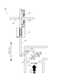
- FIG. 1 The configuration of the engine 100 will be described with reference to FIG.
- the structure of the engine 100 is typically represented with the block diagram.
- the broken line of FIG. 1 represents the electric signal line.
- the engine 100 includes a waste gate valve 60 that is an embodiment of the waste gate valve of the present invention.
- the engine 100 includes an air supply path 10, an exhaust path 20, an engine body 30, a supercharger 40, and an engine control unit (hereinafter referred to as ECU) 50 as control means.
- the engine 100 is a direct injection 6-cylinder diesel engine equipped with a supercharger.
- the air supply path 10 is a path for supplying air to the engine body 30, and is configured by connecting an air supply manifold 11, an intercooler 12, a compressor 41, and an air cleaner 14 to an air supply pipe. .
- the air supply manifold 11, the intercooler 12, the compressor 41, and the air cleaner 14 are arranged in the order of the air cleaner 14, the compressor 41, the intercooler 12, and the air supply manifold 11 from the outside toward the engine body 30.
- the air supply manifold 11, the intercooler 12, the compressor 41, and the air cleaner 14 are connected by an air supply pipe.
- the air supply manifold 11 is a manifold for introducing air into the cylinders 31 of the engine body 30.
- the intercooler 12 is a heat exchanger that cools air whose temperature has been increased by the compression of the compressor 41.
- the compressor 41 is a component of the supercharger 40 and will be described in detail later.
- the air cleaner 14 separates dust contained in the air supply with a filter medium such as a nonwoven fabric.
- the exhaust path 20 is a path for discharging air (exhaust gas) from the engine body 30 and is configured by connecting an exhaust manifold 21 and a turbine 42 to an exhaust pipe.
- the exhaust manifold 21 and the turbine 42 are arranged in the order of the exhaust manifold 21 and the turbine 42 from the engine body 30 toward the outside.
- the exhaust manifold 21 and the turbine 42 are connected by an exhaust pipe.
- the exhaust manifold 21 is a manifold that combines a plurality of exhaust pipes from the cylinders 31 of the engine main body 30 into one.
- the turbine 42 is a component of the supercharger 40 and will be described in detail later.
- the engine main body 30 includes a cylinder block (not shown), a cylinder head (not shown), and a fuel injection device 35.
- a plurality of (six) cylinders 31,..., 31 are formed in the cylinder block.
- the fuel injection device 35 is a device that injects fuel accumulated in the common rail into each cylinder by an injector.
- the supercharger 40 is a device that raises the pressure of air taken in by the engine 100 to atmospheric pressure or higher.
- the supercharger 40 includes a compressor 41 and a turbine 42.
- the turbine 42 is rotated at high speed using the internal energy of the exhaust gas discharged from the exhaust pipe.
- the compressor 41 is driven by a turbine 42 and sends compressed air from an air supply pipe to the engine 100.
- the bypass path 45 connects the upstream side and the downstream side of the turbine 42 by a bypass pipe 46.
- a waste gate valve 60 is provided in the bypass path 45. The waste gate valve 60 limits the exhaust flow rate that passes through the bypass path 45.
- the ECU 50 comprehensively electronically controls the engine 100.
- the ECU 50 is connected to the waste gate valve 60.
- the ECU 50 has a function of controlling the flow rate of the exhaust gas that passes through the bypass path 45 by controlling the opening and closing of the waste gate valve 60.
- the configuration of the waste gate valve 60 will be described with reference to FIG. In FIG. 2, the configuration of the waste gate valve 60 is shown as a partial cross-sectional view and a side view. In the following, description will be made according to the vertical direction shown in FIG.
- the waste gate valve 60 includes a drive motor 55 as drive means, a valve 61, a valve seat 62, a valve shaft 65, a drive gear 70, a valve casing 80, and a main spring 91 as first biasing means. And a damper spring 92 as a second urging means.
- the valve 61 opens and closes the flow path 82 formed in the valve casing 80 by moving from the valve seat 62.
- the valve 61 is fixed to one end side of an arm 67 that is pivotally supported by the valve shaft 65.
- the valve seat 62 is provided along the flow path 82 formed in the valve casing 80.
- the arm 67 is configured in a substantially L shape and is arranged to be rotatable about the fulcrum S.
- One end side of the arm 67 supports the valve 61.
- the other end side of the arm 67 is pivotally supported by the lower end portion of the valve shaft 65.
- a storage chamber 81 and a flow path 82 are formed in the valve casing 80.
- the storage chamber 81 is formed above the flow path 82.
- the flow path 82 is formed in a substantially L shape.
- a bypass pipe 46 is connected to the upstream side and the downstream side of the flow path 82, and a bypass path 45 is configured.
- the valve shaft 65 moves the valve 61 from the valve seat 62 by rotating the arm 67 by moving back and forth in the axial direction.
- the valve shaft 65 is disposed through the storage chamber 81 and the flow path 82 formed in the valve casing 80.
- a spiral portion 65R (lead screw) is formed in the middle portion of the valve shaft 65.
- valve shaft 65 passes through the valve casing 80 via the guide bush 64 and extends from the valve casing 80.
- a flange 63 is provided at the upper end of the valve shaft 65.
- a midway portion of the valve shaft 65 is disposed through the drive gear 70 in the storage chamber 81 by screwing the spiral portion 65R with the spiral portion 70R of the drive gear 70.
- the main spring 91 is interposed between the valve casing 80 and the flange 63, and urges the valve 61 and the valve shaft 65 upward with respect to the valve casing 80.
- the drive gear 70 is configured such that a spiral portion 70R is formed inside a substantially cylindrical shape, and a gear portion is formed in the middle portion of the substantially cylindrical shape.
- Each of the upper and lower ends of the drive gear 70 is supported by a bearing 75 so as to be rotatable with respect to the storage chamber 81 (valve casing 80).
- the drive gear 70 is configured to be slidable in the vertical direction with respect to the respective bearings 75.
- the gear portion of the drive gear 70 is screwed with the pinion 71.
- the pinion 71 is rotatably arranged in the storage chamber 81.
- the pinion 71 is screwed with the drive pinion 72.
- the drive pinion 72 is driven by the drive motor 55.
- the damper spring 92 is interposed between the bearing plate 66 and the drive gear 70 and urges the drive gear 70 downward with respect to the valve casing 80.
- the drive pinion 72 is rotationally driven by the drive motor 55, and the drive gear 70 is rotated via the pinion 71 by the drive pinion 72 being rotationally driven.
- the gear 70 is rotated, the valve shaft 65 is advanced and retracted in the axial direction, and when the valve shaft 65 is advanced and retracted in the axial direction, the arm 67 is rotated, and the valve 61 moves from the valve seat 62 and flows.
- the path 82 is opened and closed.
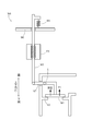
- the configuration of the waste gate valve 60 will be described with reference to FIG. In FIG. 3, the configuration of the waste gate valve 60 is schematically shown. In the following, description will be made according to the vertical direction shown in FIG. Furthermore, in FIG. 3, the valve 61 represents a fully closed state.
- the waste gate valve 60 includes the valve 61, the valve seat 62, the valve shaft 65, the drive gear 70, the valve casing 80, the main spring 91 as the first urging means, and the second attachment. And a damper spring 92 as a biasing means.
- valve 61 In the waste gate valve 60, the valve 61, the valve shaft 65 and the drive gear 70 are urged upward by the urging force F ⁇ b> 1 with respect to the valve casing 80 by the main spring 91, and the valve 61, valve shaft is urged by the damper spring 92. 65 and the drive gear 70 are urged downward by the urging force F ⁇ b> 2 with respect to the valve casing 80.
- the main spring 91 and the damper spring 92 are configured such that when the valve 61 is fully open, the force acting on the exhaust pressure of the exhaust gas passing through the flow path 82 acting on the valve 61 and the main spring acting on the valve 61.
- the load and the spring constant are set so that the urging force F1 of 91 and the urging force F2 of the damper spring 92 acting on the valve 61 are balanced.
- valve 61, the valve shaft 65, and the drive gear 70 are configured so that all the forces acting on the valve 61 including the force acting by the exhaust gas exhaust pressure are balanced in the fully opened state.
- FIG. 4 the operation of the waste gate valve 60 is schematically shown. In FIG. 4, the valve 61 is fully opened.
- the valve 61, the valve shaft 65, and the drive gear 70 are configured so that all the forces acting on the valve 61 including the force acting on the exhaust gas exhaust pressure are balanced in a fully opened state. Therefore, it is configured to be capable of minute vibrations at a predetermined opening position.
- pulsation may occur in the exhaust gas exhaust pressure passing through the flow path 82.
- the valve 61 follows the vibration of the exhaust pressure in synchronization with the pulsation of the exhaust pressure. Will be absorbed.
- the pulsation can be absorbed following the pulsation of the exhaust gas.
- the waste gate valve of the present invention is the waste gate valve 60.
- the waste gate valve of the present invention may be EGR (Exhaust Gas Recirculation).
- the present invention can be used for an engine.
Landscapes
- Engineering & Computer Science (AREA)
- General Engineering & Computer Science (AREA)
- Mechanical Engineering (AREA)
- Chemical & Material Sciences (AREA)
- Combustion & Propulsion (AREA)
- Supercharger (AREA)
- Mechanically-Actuated Valves (AREA)
Abstract
流体圧の脈動に追従して脈動を吸収することができるウェイストゲートバルブを提供する。駆動モータ(55)によって駆動ギア(70)を回転駆動し、駆動ギア(70)を回転駆動することによって駆動ギア(70)に螺合されるバルブシャフト(65)を軸方向に進退させ、バルブシャフト(65)を進退させることによってバルブシャフト(65)に設けられたバルブ(61)をバルブシート(62)から移動させて流路(82)を開閉させ、バルブ(61)を閉方向に向けて付勢するメインスプリング(91)を備え、バルブ(61)に作用する流体圧力が駆動モータ(55)に対し負荷として伝達されるウェイストゲートバルブ(60)であって、バルブ(61)を開方向に向けて付勢するダンパースプリング(92)が設けられる。
Description
本発明は、ウェイストゲートバルブの技術に関する。
ウェイストゲートバルブは、バルブがバルブシートから移動して流路を開閉する構造のバルブとして公知である(例えば、特許文献1)。ウェイストゲートバルブは、過給機に設けられ、排気ガスの一部を分流させることによりタービンへの排気ガスの流入量を調節するものである。
ところで、排気経路では、排気ガスの排圧が脈動してタービンの効率が低下する場合がある。そこで、排圧の脈動を抑えるべく、ウェイストゲートバルブを排圧の脈動に追従させて排圧の脈動を吸収することが考えられる。以下に、従来のウェイストゲートバルブとしてウェイストゲートバルブ160について説明する。
図5を用いて、ウェイストゲートバルブ160の構成について説明する。
なお、図5では、ウェイストゲートバルブ160の構成を模式的に表している。また、図5では、バルブ161が全閉の状態を表している。
なお、図5では、ウェイストゲートバルブ160の構成を模式的に表している。また、図5では、バルブ161が全閉の状態を表している。
ウェイストゲートバルブ160は、バルブ161と、バルブシート162と、バルブシャフト165と、駆動ギア170と、バルブケーシング180と、メインスプリング191と、を具備している。
ウェイストゲートバルブ160では、駆動モータによって駆動ギア170が回転駆動され、駆動ギア170が回転駆動することによってバルブシャフト165が軸方向に進退され、バルブシャフト165が軸方向に進退されることによって、アーム167が支点Sを中心に回動し、バルブ161がバルブシート162から移動して流路が開閉される。
このとき、ウェイストゲートバルブ160では、メインスプリング191によって、バルブ161、バルブシャフト165及び駆動ギア170がバルブケーシング180に対して上下方向の上側に向けて付勢力F1によって付勢され、流路を通過する排気ガスの排圧によって作用する力が上下方向の上側に向けて付勢されている。そのため、ウェイストゲートバルブ160は、常時、上下方向の上側に向けて付勢されていることになる。
つまり、ウェイストゲートバルブ160では、バルブ161が常時、上下方向の上側に向けて付勢されているため、排圧の脈動速度に追従することができない。また、駆動モータによるバルブ161の開閉制御では、排圧の脈動速度に追従することができない。
本発明の解決しようとする課題は、流体圧の脈動に追従して脈動を吸収することができるウェイストゲートバルブを提供することである。
本発明のウェイストゲートバルブにおいては、駆動手段によって駆動ギアを回転駆動し、該駆動ギアを回転駆動することによって該駆動ギアに螺合されるバルブシャフトを軸方向に進退させ、該バルブシャフトを進退させることによって該バルブシャフトに設けられたバルブをバルブシートから移動させて流路を開閉させ、該バルブを閉方向に向けて付勢する第一付勢手段を備え、該バルブに作用する流体圧力が前記駆動手段に対し負荷として伝達されるウェイストゲートバルブであって、前記バルブを開方向に向けて付勢する第二付勢手段が設けられることが好ましい。
本発明のウェイストゲートバルブにおいては、前記第一付勢手段及び前記第二付勢手段のそれぞれの付勢力は、前記バルブが全開の状態にて前記流路を通過する流体圧が作用する力と該第一付勢手段の付勢力と該第二付勢手段の付勢力とがつり合うように設定されているものである。
本発明のウェイストゲートバルブによれば、流体圧の脈動に追従して脈動を吸収することができる。
図1を用いて、エンジン100の構成について説明する。
なお、図1では、エンジン100の構成をブロック線図にて模式的に表している。また、図1の破線は、電気信号線を表している。
なお、図1では、エンジン100の構成をブロック線図にて模式的に表している。また、図1の破線は、電気信号線を表している。
エンジン100は、本発明のウェイストゲートバルブの実施形態であるウェイストゲートバルブ60を備えるものである。エンジン100は、給気経路10と、排気経路20と、エンジン本体30と、過給機40と、制御手段としてのEngine Control Unit(以下、ECU)50と、を備えている。エンジン100は、過給機を備えた直噴式6気筒ディーゼルエンジンとされている。
給気経路10は、エンジン本体30に空気を供給する経路であって、給気配管に給気マニホールド11と、インタークーラー12と、コンプレッサ41と、エアクリーナー14と、を接続して構成されている。
給気マニホールド11、インタークーラー12、コンプレッサ41及びエアクリーナー14は、外部からエンジン本体30に向かって、エアクリーナー14、コンプレッサ41、インタークーラー12、給気マニホールド11の順に配置されている。給気マニホールド11、インタークーラー12、コンプレッサ41及びエアクリーナー14は、給気配管によって接続されている。
給気マニホールド11は、エンジン本体30の気筒31、・・・・、31に空気を導入するための多岐管である。インタークーラー12は、コンプレッサ41の圧縮により温度が上がった空気を冷却する熱交換器である。コンプレッサ41は、過給機40の構成部品であって詳しくは後述する。エアクリーナー14は、不織布等の濾材で給気中に含まれる粉塵などを分離するものである。
排気経路20は、エンジン本体30から空気(排気)を排出する経路であって、排気管に排気マニホールド21と、タービン42と、を接続して構成されている。排気マニホールド21、タービン42は、エンジン本体30から外部に向かって、排気マニホールド21、タービン42の順に配置されている。排気マニホールド21、タービン42は、排気管によって接続されている。
排気マニホールド21は、エンジン本体30の気筒31、・・・・、31からの複数の排気管を1つにまとめる多岐管である。タービン42は、過給機40の構成部品であって詳しくは後述する。
エンジン本体30は、シリンダブロック(図示略)と、シリンダヘッド(図示略)と、燃料噴射装置35と、を備えている。シリンダブロックには、複数(6つ)の気筒31、・・・・、31が形成されている。燃料噴射装置35は、コモンレールに蓄圧された燃料をインジェクタによって各気筒に噴射する装置である。
過給機40は、エンジン100が吸入する空気の圧力を大気圧以上に高める装置である。過給機40は、コンプレッサ41と、タービン42と、を備えている。タービン42は、排気配管から排出される排気ガスの内部エネルギーを利用して高速回転されるものである。コンプレッサ41は、タービン42によって駆動され、圧縮した空気を給気管からエンジン100に送り込むものである。
バイパス経路45は、バイパス配管46によってタービン42の上流側と下流側とを接続している。バイパス経路45には、ウェイストゲートバルブ60が設けられている。ウェイストゲートバルブ60は、バイパス経路45を通過する排気流量を制限するものである。
ECU50は、エンジン100を総合的に電子制御するものである。ECU50は、ウェイストゲートバルブ60と接続されている。ECU50は、ウェイストゲートバルブ60を開閉制御して、バイパス経路45を通過する排気の流量を制御する機能を有している。
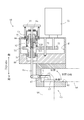
図2を用いて、ウェイストゲートバルブ60の構成について説明する。
なお、図2では、ウェイストゲートバルブ60の構成を一部断面視かつ側面視として表している。また、以下では図2に示す上下方向に従って説明するものとする。
なお、図2では、ウェイストゲートバルブ60の構成を一部断面視かつ側面視として表している。また、以下では図2に示す上下方向に従って説明するものとする。
ウェイストゲートバルブ60は、駆動手段としての駆動モータ55と、バルブ61と、バルブシート62と、バルブシャフト65と、駆動ギア70と、バルブケーシング80と、第一付勢手段としてのメインスプリング91と、第二付勢手段としてのダンパースプリング92と、を具備している。
バルブ61は、バルブシート62から移動することによってバルブケーシング80に形成される流路82を開閉するものである。バルブ61は、バルブシャフト65に軸支されるアーム67の一端側に固設されている。バルブシート62は、バルブケーシング80に形成される流路82の途上に設けられている。
アーム67は略L字形状に構成され、支点Sを中心に回動自在に配置されている。アーム67の一端側は、バルブ61を支持している。アーム67の他端側は、バルブシャフト65の下端部に軸支されている。
バルブケーシング80には、収納室81と、流路82と、が形成されている。収納室81は、流路82の上側に形成されている。流路82は、略L字形状に形成されている。流路82の上流側及び下流側には、バイパス配管46が接続され、バイパス経路45が構成されている。
バルブシャフト65は、軸方向に進退することによって、アーム67を回動してバルブ61をバルブシート62から移動させるものである。バルブシャフト65は、バルブケーシング80に形成される収納室81及び流路82を貫通して配置されている。バルブシャフト65の中途部には螺旋部65R(リードスクリュー)が形成されている。
バルブシャフト65の上側は、ガイドブッシュ64を介してバルブケーシング80を貫通して、バルブケーシング80から延出されている。バルブシャフト65の上側先端には、フランジ63が設けられている。バルブシャフト65の中途部は、収納室81にて、螺旋部65Rを駆動ギア70の螺旋部70Rに螺合させて、駆動ギア70を貫通して配置されている。
メインスプリング91は、バルブケーシング80とフランジ63との間に介装され、バルブ61及びバルブシャフト65をバルブケーシング80に対して上側に向けて付勢している。
駆動ギア70は、略円筒形状の内部に螺旋部70Rが形成され、略円筒形状の中途部にギア部が形成されて構成されている。駆動ギア70は、上下端部のそれぞれがベアリング75によって収納室81(バルブケーシング80)に対して回動可能に支持されている。また、駆動ギア70は、それぞれのベアリング75に対して上下方向に摺動可能に構成されている。
駆動ギア70のギア部は、ピニオン71と螺合されている。ピニオン71は、収納室81にて回動自在に配置されている。ピニオン71は、駆動ピニオン72と螺合されている。駆動ピニオン72は、駆動モータ55によって駆動されるものである。
ダンパースプリング92は、ベアリングプレート66と駆動ギア70との間に介装され、駆動ギア70をバルブケーシング80に対して下側に向けて付勢している。
このような構成とすることで、ウェイストゲートバルブ60では、駆動モータ55によって駆動ピニオン72が回転駆動され、駆動ピニオン72が回転駆動されることによってピニオン71を介して駆動ギア70が回転され、駆動ギア70が回転されることによってバルブシャフト65が軸方向に進退され、バルブシャフト65が軸方向に進退されることによって、アーム67を回動して、バルブ61がバルブシート62から移動して流路82が開閉される。
なお、ウェイストゲートバルブ60では、バルブ61に作用する流体圧力が駆動モータ55に対し負荷として伝達されるものとする。
図3を用いて、ウェイストゲートバルブ60の構成について説明する。
なお、図3では、ウェイストゲートバルブ60の構成を模式的に表している。また、以下では図3に示す上下方向に従って説明するものとする。さらに、図3では、バルブ61が全閉の状態を表している。
なお、図3では、ウェイストゲートバルブ60の構成を模式的に表している。また、以下では図3に示す上下方向に従って説明するものとする。さらに、図3では、バルブ61が全閉の状態を表している。
ウェイストゲートバルブ60は、上述したように、バルブ61と、バルブシート62と、バルブシャフト65と、駆動ギア70と、バルブケーシング80と、第一付勢手段としてのメインスプリング91と、第二付勢手段としてのダンパースプリング92と、を具備している。
ウェイストゲートバルブ60では、メインスプリング91によって、バルブ61、バルブシャフト65及び駆動ギア70がバルブケーシング80に対して上側に向けて付勢力F1によって付勢され、ダンパースプリング92によって、バルブ61、バルブシャフト65及び駆動ギア70がバルブケーシング80に対して下側に向けて付勢力F2によって付勢されている。
ここで、メインスプリング91及びダンパースプリング92は、バルブ61が全開の状態にて、バルブ61に作用する流路82を通過する排気ガスの排圧によって作用する力と、バルブ61に作用するメインスプリング91の付勢力F1と、バルブ61に作用するダンパースプリング92の付勢力F2と、がつり合うようにそれぞれ荷重とバネ定数が設定されている。
言い換えれば、バルブ61、バルブシャフト65及び駆動ギア70は、全開の状態にて、排気ガスの排圧によって作用する力を含めたバルブ61に作用する力が全てつり合うように構成されている。
図4を用いて、ウェイストゲートバルブ60の作用について説明する。
なお、図4では、ウェイストゲートバルブ60の作用を模式的に表している。また、図4では、バルブ61が全開の状態を表している。
なお、図4では、ウェイストゲートバルブ60の作用を模式的に表している。また、図4では、バルブ61が全開の状態を表している。
ウェイストゲートバルブ60では、バルブ61、バルブシャフト65及び駆動ギア70は、全開の状態にて、排気ガスの排圧によって作用する力を含めたバルブ61に作用する力が全てつり合うように構成されているため、所定の開度位置にて微小振動可能なように構成されている。
ウェイストゲートバルブ60では、流路82を通過する排気ガスの排圧に脈動が発生する場合がある。このとき、ウェイストゲートバルブ60が微小振動可能なように構成されているため、排圧の脈動に同調してバルブ61が微小振動して追従し、バルブ61の微小振動挙動に排圧の脈動が吸収されることになる。
ウェイストゲートバルブ60の効果について説明する。
ウェイストゲートバルブ60によれば、排気ガスの脈動に追従して脈動を吸収することができる。
ウェイストゲートバルブ60によれば、排気ガスの脈動に追従して脈動を吸収することができる。
なお、本実施形態では、本発明のウェイストゲートバルブをウェイストゲートバルブ60とする構成としたがこれに限定されない。本発明のウェイストゲートバルブをEGR(Exhaust Gas Recirculation)とする構成であっても良い。
本発明は、エンジンに利用可能である。
60 ウェイストゲートバルブ
61 バルブ
62 バルブシート
65 バルブシャフト
70 駆動ギア
80 バルブケーシング
91 メインスプリング(第一付勢手段)
92 ダンパースプリング(第二付勢手段)
100 エンジン
61 バルブ
62 バルブシート
65 バルブシャフト
70 駆動ギア
80 バルブケーシング
91 メインスプリング(第一付勢手段)
92 ダンパースプリング(第二付勢手段)
100 エンジン
Claims (2)
- 駆動手段によって駆動ギアを回転駆動し、該駆動ギアを回転駆動することによって該駆動ギアに螺合されるバルブシャフトを軸方向に進退させ、該バルブシャフトを進退させることによって該バルブシャフトに設けられたバルブをバルブシートから移動させて流路を開閉させ、該バルブを閉方向に向けて付勢する第一付勢手段を備え、該バルブに作用する流体圧力が前記駆動手段に対し負荷として伝達されるウェイストゲートバルブであって、
前記バルブを開方向に向けて付勢する第二付勢手段が設けられる、
ウェイストゲートバルブ。 - 請求項1記載のウェイストゲートバルブであって、
前記第一付勢手段及び前記第二付勢手段のそれぞれの付勢力は、前記バルブが全開の状態にて前記流路を通過する流体圧が作用する力と該第一付勢手段の付勢力と該第二付勢手段の付勢力とがつり合うように設定されている、
ウェイストゲートバルブ。
Priority Applications (3)
| Application Number | Priority Date | Filing Date | Title |
|---|---|---|---|
| US15/511,438 US20170292631A1 (en) | 2014-11-10 | 2015-11-05 | Waste gate valve |
| CN201580058432.0A CN107076014A (zh) | 2014-11-10 | 2015-11-05 | 废气泄压阀 |
| EP15858128.0A EP3219950A4 (en) | 2014-11-10 | 2015-11-05 | Waste gate valve |
Applications Claiming Priority (2)
| Application Number | Priority Date | Filing Date | Title |
|---|---|---|---|
| JP2014-228493 | 2014-11-10 | ||
| JP2014228493A JP2016089792A (ja) | 2014-11-10 | 2014-11-10 | ウェイストゲートバルブ |
Publications (1)
| Publication Number | Publication Date |
|---|---|
| WO2016076206A1 true WO2016076206A1 (ja) | 2016-05-19 |
Family
ID=55954295
Family Applications (1)
| Application Number | Title | Priority Date | Filing Date |
|---|---|---|---|
| PCT/JP2015/081229 Ceased WO2016076206A1 (ja) | 2014-11-10 | 2015-11-05 | ウェイストゲートバルブ |
Country Status (5)
| Country | Link |
|---|---|
| US (1) | US20170292631A1 (ja) |
| EP (1) | EP3219950A4 (ja) |
| JP (1) | JP2016089792A (ja) |
| CN (1) | CN107076014A (ja) |
| WO (1) | WO2016076206A1 (ja) |
Families Citing this family (11)
| Publication number | Priority date | Publication date | Assignee | Title |
|---|---|---|---|---|
| CN108591491A (zh) * | 2018-06-30 | 2018-09-28 | 唐山三友盐化有限公司 | 盐池排水装置 |
| US11828239B2 (en) | 2018-12-07 | 2023-11-28 | Polaris Industries Inc. | Method and system for controlling a turbocharged two stroke engine based on boost error |
| US11639684B2 (en) | 2018-12-07 | 2023-05-02 | Polaris Industries Inc. | Exhaust gas bypass valve control for a turbocharger for a two-stroke engine |
| US11174779B2 (en) | 2018-12-07 | 2021-11-16 | Polaris Industries Inc. | Turbocharger system for a two-stroke engine |
| US11725573B2 (en) | 2018-12-07 | 2023-08-15 | Polaris Industries Inc. | Two-passage exhaust system for an engine |
| US20200182164A1 (en) | 2018-12-07 | 2020-06-11 | Polaris Industries Inc. | Method And System For Predicting Trapped Air Mass In A Two-Stroke Engine |
| US11384697B2 (en) | 2020-01-13 | 2022-07-12 | Polaris Industries Inc. | System and method for controlling operation of a two-stroke engine having a turbocharger |
| CA3217527A1 (en) | 2020-01-13 | 2021-07-13 | Polaris Industries Inc. | Turbocharger lubrication system for a two-stroke engine |
| US11788432B2 (en) | 2020-01-13 | 2023-10-17 | Polaris Industries Inc. | Turbocharger lubrication system for a two-stroke engine |
| CA3201948A1 (en) * | 2020-01-13 | 2021-07-13 | Polaris Industries Inc. | Turbocharger system for a two-stroke engine having selectable boost modes |
| CN111911282A (zh) * | 2020-08-18 | 2020-11-10 | 吉林大学 | 一种发动机二级涡轮增压器用电控阀系统及控制方法 |
Citations (3)
| Publication number | Priority date | Publication date | Assignee | Title |
|---|---|---|---|---|
| JPH0610775A (ja) * | 1992-06-30 | 1994-01-18 | Fuji Oozx Inc | 流体制御用バルブ装置 |
| JP2000039082A (ja) * | 1999-07-22 | 2000-02-08 | Mitsubishi Electric Engineering Co Ltd | 電動制御弁装置 |
| WO2011111090A1 (ja) * | 2010-03-09 | 2011-09-15 | 三菱電機株式会社 | ターボ用ウェストゲートアクチュエータ |
Family Cites Families (10)
| Publication number | Priority date | Publication date | Assignee | Title |
|---|---|---|---|---|
| JPS594534B2 (ja) * | 1978-05-12 | 1984-01-30 | 川崎重工業株式会社 | 車両用過給エンジンの制御機構 |
| JP2978677B2 (ja) * | 1993-07-07 | 1999-11-15 | 三菱電機エンジニアリング株式会社 | 電動制御弁装置 |
| US5364066A (en) * | 1993-07-15 | 1994-11-15 | Sporlan Valve Company | Dual port valve with stepper motor actuator |
| JP3204043B2 (ja) * | 1995-06-22 | 2001-09-04 | 日産自動車株式会社 | 流量制御バルブ |
| US6227183B1 (en) * | 1998-05-06 | 2001-05-08 | Mitsubishi Denki Kabushiki Kaisha | Mounting device for exhaust gas re-circulation valve |
| US7017882B2 (en) * | 2004-05-10 | 2006-03-28 | Eaton Corporation | Valve assembly |
| WO2011062944A1 (en) * | 2009-11-18 | 2011-05-26 | Parker Hannifin Corporation | Electric expansion valve |
| US9702479B2 (en) * | 2011-12-27 | 2017-07-11 | Taiho Kogyo Co., Ltd. | Rotationally driven poppet valve |
| JP5988853B2 (ja) * | 2012-12-07 | 2016-09-07 | 愛三工業株式会社 | 排気還流バルブ |
| DE112015006422B4 (de) * | 2015-04-06 | 2022-02-17 | Mitsubishi Electric Corporation | Wastegate-Stellantrieb und Wastegate-Ventil-Antriebseinrichtung |
-
2014
- 2014-11-10 JP JP2014228493A patent/JP2016089792A/ja active Pending
-
2015
- 2015-11-05 EP EP15858128.0A patent/EP3219950A4/en not_active Withdrawn
- 2015-11-05 CN CN201580058432.0A patent/CN107076014A/zh active Pending
- 2015-11-05 US US15/511,438 patent/US20170292631A1/en not_active Abandoned
- 2015-11-05 WO PCT/JP2015/081229 patent/WO2016076206A1/ja not_active Ceased
Patent Citations (3)
| Publication number | Priority date | Publication date | Assignee | Title |
|---|---|---|---|---|
| JPH0610775A (ja) * | 1992-06-30 | 1994-01-18 | Fuji Oozx Inc | 流体制御用バルブ装置 |
| JP2000039082A (ja) * | 1999-07-22 | 2000-02-08 | Mitsubishi Electric Engineering Co Ltd | 電動制御弁装置 |
| WO2011111090A1 (ja) * | 2010-03-09 | 2011-09-15 | 三菱電機株式会社 | ターボ用ウェストゲートアクチュエータ |
Non-Patent Citations (1)
| Title |
|---|
| See also references of EP3219950A4 * |
Also Published As
| Publication number | Publication date |
|---|---|
| EP3219950A4 (en) | 2018-04-11 |
| EP3219950A1 (en) | 2017-09-20 |
| JP2016089792A (ja) | 2016-05-23 |
| US20170292631A1 (en) | 2017-10-12 |
| CN107076014A (zh) | 2017-08-18 |
Similar Documents
| Publication | Publication Date | Title |
|---|---|---|
| WO2016076206A1 (ja) | ウェイストゲートバルブ | |
| JP6059299B2 (ja) | 燃焼機関用強制導入装置、燃焼機関及び燃焼機関の動作方法 | |
| KR101324882B1 (ko) | 웨이스트 게이트 밸브 | |
| CN104879206B (zh) | 发动机的排气装置 | |
| KR101794365B1 (ko) | 내연 엔진용 신선 가스 공급 장치 및 이런 신선 가스 공급 장치의 작동 방법 | |
| US10234038B2 (en) | Valve | |
| CN102099554A (zh) | 用于燃料计量的装置 | |
| CN105020069B (zh) | 一种可变进气歧管长度的fsae赛车进气系统 | |
| JP5863490B2 (ja) | 内燃機関の吸気循環装置 | |
| US20160090928A1 (en) | Exhaust control apparatus for engine | |
| JP2017057813A (ja) | アクチュエータの動弁機構 | |
| KR20120109414A (ko) | 연소엔진, 청정공기시스템 및 관련 작동방법 | |
| US8695336B2 (en) | Exhaust gas waste gate system with charge pressure control | |
| KR101526388B1 (ko) | 엔진 시스템 | |
| KR20110049153A (ko) | Cng엔진의 공기량 제어장치 | |
| KR20120015386A (ko) | 터보차져의 웨이스트 게이트 작동 제어 시스템 | |
| JP2017057814A (ja) | アクチュエータの動弁機構 | |
| JP2016098953A (ja) | アクチュエータの動弁機構 | |
| JP2016514797A (ja) | 排気ガスターボチャージャ | |
| CN204941705U (zh) | 一种用于提高涡轮增压柴油机制动功率的装置 | |
| JP2013532254A (ja) | 内燃機関用の新鮮ガス供給装置 | |
| JP6044572B2 (ja) | ターボ過給機付エンジンの制御装置 | |
| JP5682163B2 (ja) | 過給補助付き過給装置及び放出調節バルブ | |
| JP2018059495A (ja) | エンジンシステム | |
| CN105736197B (zh) | 内燃式发动机进气系统及其控制装置和方法 |
Legal Events
| Date | Code | Title | Description |
|---|---|---|---|
| 121 | Ep: the epo has been informed by wipo that ep was designated in this application |
Ref document number: 15858128 Country of ref document: EP Kind code of ref document: A1 |
|
| REEP | Request for entry into the european phase |
Ref document number: 2015858128 Country of ref document: EP |
|
| WWE | Wipo information: entry into national phase |
Ref document number: 2015858128 Country of ref document: EP |
|
| WWE | Wipo information: entry into national phase |
Ref document number: 15511438 Country of ref document: US |
|
| NENP | Non-entry into the national phase |
Ref country code: DE |