WO2016076346A1 - 穿孔プラスチックフィルム - Google Patents
穿孔プラスチックフィルム Download PDFInfo
- Publication number
- WO2016076346A1 WO2016076346A1 PCT/JP2015/081695 JP2015081695W WO2016076346A1 WO 2016076346 A1 WO2016076346 A1 WO 2016076346A1 JP 2015081695 W JP2015081695 W JP 2015081695W WO 2016076346 A1 WO2016076346 A1 WO 2016076346A1
- Authority
- WO
- WIPO (PCT)
- Prior art keywords
- plastic film
- film
- tearing
- perforated plastic
- perforated
- Prior art date
- Legal status (The legal status is an assumption and is not a legal conclusion. Google has not performed a legal analysis and makes no representation as to the accuracy of the status listed.)
- Ceased
Links
Images

Classifications
-
- A—HUMAN NECESSITIES
- A61—MEDICAL OR VETERINARY SCIENCE; HYGIENE
- A61F—FILTERS IMPLANTABLE INTO BLOOD VESSELS; PROSTHESES; DEVICES PROVIDING PATENCY TO, OR PREVENTING COLLAPSING OF, TUBULAR STRUCTURES OF THE BODY, e.g. STENTS; ORTHOPAEDIC, NURSING OR CONTRACEPTIVE DEVICES; FOMENTATION; TREATMENT OR PROTECTION OF EYES OR EARS; BANDAGES, DRESSINGS OR ABSORBENT PADS; FIRST-AID KITS
- A61F13/00—Bandages or dressings; Absorbent pads
- A61F13/15—Absorbent pads, e.g. sanitary towels, swabs or tampons for external or internal application to the body; Supporting or fastening means therefor; Tampon applicators
- A61F13/51—Absorbent pads, e.g. sanitary towels, swabs or tampons for external or internal application to the body; Supporting or fastening means therefor; Tampon applicators characterised by the outer layers of the pads
- A61F13/511—Topsheet, i.e. the permeable cover or layer facing the skin
- A61F13/512—Topsheet, i.e. the permeable cover or layer facing the skin characterised by its apertures, e.g. perforations
-
- A—HUMAN NECESSITIES
- A61—MEDICAL OR VETERINARY SCIENCE; HYGIENE
- A61F—FILTERS IMPLANTABLE INTO BLOOD VESSELS; PROSTHESES; DEVICES PROVIDING PATENCY TO, OR PREVENTING COLLAPSING OF, TUBULAR STRUCTURES OF THE BODY, e.g. STENTS; ORTHOPAEDIC, NURSING OR CONTRACEPTIVE DEVICES; FOMENTATION; TREATMENT OR PROTECTION OF EYES OR EARS; BANDAGES, DRESSINGS OR ABSORBENT PADS; FIRST-AID KITS
- A61F13/00—Bandages or dressings; Absorbent pads
- A61F13/01—Non-adhesive bandages or dressings
- A61F13/01034—Non-adhesive bandages or dressings characterised by a property
- A61F13/01046—Air-vapor permeability
-
- A—HUMAN NECESSITIES
- A61—MEDICAL OR VETERINARY SCIENCE; HYGIENE
- A61L—METHODS OR APPARATUS FOR STERILISING MATERIALS OR OBJECTS IN GENERAL; DISINFECTION, STERILISATION OR DEODORISATION OF AIR; CHEMICAL ASPECTS OF BANDAGES, DRESSINGS, ABSORBENT PADS OR SURGICAL ARTICLES; MATERIALS FOR BANDAGES, DRESSINGS, ABSORBENT PADS OR SURGICAL ARTICLES
- A61L15/00—Chemical aspects of, or use of materials for, bandages, dressings or absorbent pads
-
- A—HUMAN NECESSITIES
- A61—MEDICAL OR VETERINARY SCIENCE; HYGIENE
- A61F—FILTERS IMPLANTABLE INTO BLOOD VESSELS; PROSTHESES; DEVICES PROVIDING PATENCY TO, OR PREVENTING COLLAPSING OF, TUBULAR STRUCTURES OF THE BODY, e.g. STENTS; ORTHOPAEDIC, NURSING OR CONTRACEPTIVE DEVICES; FOMENTATION; TREATMENT OR PROTECTION OF EYES OR EARS; BANDAGES, DRESSINGS OR ABSORBENT PADS; FIRST-AID KITS
- A61F13/00—Bandages or dressings; Absorbent pads
- A61F2013/00089—Wound bandages
- A61F2013/00246—Wound bandages in a special way pervious to air or vapours
- A61F2013/00251—Wound bandages in a special way pervious to air or vapours with macroscopic openings
-
- A—HUMAN NECESSITIES
- A61—MEDICAL OR VETERINARY SCIENCE; HYGIENE
- A61F—FILTERS IMPLANTABLE INTO BLOOD VESSELS; PROSTHESES; DEVICES PROVIDING PATENCY TO, OR PREVENTING COLLAPSING OF, TUBULAR STRUCTURES OF THE BODY, e.g. STENTS; ORTHOPAEDIC, NURSING OR CONTRACEPTIVE DEVICES; FOMENTATION; TREATMENT OR PROTECTION OF EYES OR EARS; BANDAGES, DRESSINGS OR ABSORBENT PADS; FIRST-AID KITS
- A61F13/00—Bandages or dressings; Absorbent pads
- A61F2013/00089—Wound bandages
- A61F2013/00246—Wound bandages in a special way pervious to air or vapours
- A61F2013/00255—Wound bandages in a special way pervious to air or vapours with pores
-
- A—HUMAN NECESSITIES
- A61—MEDICAL OR VETERINARY SCIENCE; HYGIENE
- A61F—FILTERS IMPLANTABLE INTO BLOOD VESSELS; PROSTHESES; DEVICES PROVIDING PATENCY TO, OR PREVENTING COLLAPSING OF, TUBULAR STRUCTURES OF THE BODY, e.g. STENTS; ORTHOPAEDIC, NURSING OR CONTRACEPTIVE DEVICES; FOMENTATION; TREATMENT OR PROTECTION OF EYES OR EARS; BANDAGES, DRESSINGS OR ABSORBENT PADS; FIRST-AID KITS
- A61F13/00—Bandages or dressings; Absorbent pads
- A61F2013/00089—Wound bandages
- A61F2013/00246—Wound bandages in a special way pervious to air or vapours
- A61F2013/00263—Wound bandages in a special way pervious to air or vapours vapour permeability >500 g/m2/24h
Definitions
- the present invention relates to a perforated plastic film having a large number of through holes.
- the present invention relates to a plastic film that has low skin irritation (skin irritation) and is suitable for use in protecting the skin.
- plastic films such as polyurethane have been used for skin protection such as wound prevention and wound treatment.
- skin protection such as wound prevention and wound treatment.
- the plastic film has a problem that it is difficult to appropriately release moisture evaporated from human skin, and the skin is steamed and macerated to become brittle, and the macerated portion induces a wound.
- porous films with improved moisture permeability have been proposed.
- Patent Document 1 proposes a wound protective material comprising a fiber aggregate on which metal is deposited, a fiber aggregate for absorbing body fluid, and a microporous film having water repellency.
- the pore diameter is usually 100 to 100 ⁇ m, and the porosity is usually 5 to 90%.
- Patent Document 2 a sheet-like material for wound dressing composed of a water vapor permeable polymer material and a porous polymer material is proposed, and a porous polymer material having a porosity of 40% or more is 20 ⁇ m or less.
- the water vapor permeability is 130 g / m 2 ⁇ hr or more by combining with the silicone layer.
- Patent Document 3 proposes that a soft elastomer film with a hole is used as a wound bandage in combination with a gas-permeable fabric pad, and the end of the hole is not sharp and the wound tissue is not easily damaged. Is described.
- Patent Document 3 a soft elastomer is used as a film material so that the end of the hole does not become sharp, but on the contrary, the coefficient of friction against the skin becomes high and the skin irritation is low. That's not true.
- an object of the present invention is to provide a plastic film having moderate moisture permeability and low skin irritation.
- the present inventors have provided a large number of through-holes by perforating instead of a so-called porous film having a large number of discontinuous fine holes therein.
- a plastic film By using a plastic film, it was conceived that a desired moisture permeability can be easily realized by using a film made of any polymer material. Further, the inventors have found that a plastic film having a large number of through-holes has a moisture permeability of 300 to 3500 g / m 2 ⁇ 24 hr, has low skin irritation, and can be used for skin protection, thereby completing the present invention. I let you.
- a perforated plastic film comprising a plastic film having a large number of through-holes and having a moisture permeability of 300 to 3500 g / m 2 ⁇ 24 h.
- the acute angle between the tear direction and the cutting line when tearing in the direction of 45 ° with the flow direction is 30 to 60 °, and the tear strength when tearing in the direction of 45 ° with the flow direction is 10 g or less
- tear in either the flow direction or the width direction tear in either the flow direction or the width direction.
- the acute angle between the tear direction and the cutting line when it tears in the direction of 45 ° with the flow direction is 30 to 60 °, and the tear strength when it tears in the direction of 45 ° with the flow direction is 10 g or less.
- Preparing a plastic film A method for producing a perforated plastic film, comprising a perforating process step of forming a large number of holes in the plastic film. [11] The method for producing a perforated plastic film according to [10], wherein the step of preparing the plastic film includes a step of electron beam cross-linking the plastic film. [12] A composite comprising a nonwoven fabric and the perforated plastic film according to any one of [1] to [8]. [13] A wound body including a core tube and the perforated plastic film according to any one of [1] to [8] wound around the core tube.
- a plastic film having moderate moisture permeability and low skin irritation can be provided.
- the perforated plastic film of the present invention is a plastic film having a large number of through holes and a moisture permeability of 300 to 3500 g / m 2 ⁇ 24 h.
- the moisture permeability referred to here is a moisture permeability test method described later, and measures the mass of water vapor that passes through the film at 40 ° C. and a humidity of 50%, and the obtained measurement value per 1 m 2 ⁇ 24 hours of the film. The value converted to. Further, the number of through holes is 10 to 40000 co / 100 cm 2 .
- Patent Document 2 There are various parameters for evaluating the water vapor transmission rate.
- Patent Document 2 described above employs a measurement method in which a sample is directly immersed in water.
- parameters based on this method of directly immersing the sample in water should be measured when evaluating the water vapor permeability of the sample from the standpoint of skin maceration and resistance to drying when applied to the skin. Since the environment is very different from the actual usage situation, it is not suitable for the purpose of evaluation. Therefore, even if the water vapor transmission rate is set to a specific range using such parameters (for example, a range equivalent to a value referred to as a water vapor transpiration rate from the wound surface), actually, the skin irritation is sufficiently low. It is thought that it was not a thing.
- the moisture permeability employed in the present invention measures the mass of water vapor that passes through the sample in a normal outside air environment (40 ° C., humidity 50%), and the measurement environment is a skin protective film. It is suitable for evaluating the characteristics (hardness of maceration and drying) of films for skin protection applications.
- the water vapor transmission rate of the plastic film is set within a range of 300 to 3500 g / m 2 ⁇ 24 h, the water evaporated from the human skin is appropriately released, and the water is vaporized and softened.
- the skin irritation can be suppressed without excessively drying and without reducing the physical irritation due to the friction when the film slides on the skin and the wound as described below and without impairing the cutting ability.
- the water vapor transmission rate is 300 to 2000 g / m 2 ⁇ 24 h.
- the moisture permeability is set within this range, the moisture state of the skin can be kept moderate and skin irritation can be suppressed. More preferably 300 ⁇ 1800g / m 2 ⁇ 24h , and most preferably 600 ⁇ 1700g / m 2 ⁇ 24h .
- the moisture permeability of the perforated plastic film in this embodiment is the total amount of moisture permeability derived from moisture passing through the through-hole part and moisture permeability derived from moisture passing through the plastic part.
- the former depends on the aperture ratio of the holes, and the latter depends on the material (water vapor permeability, etc.) and thickness of the plastic film.
- the moisture permeability may be adjusted by any of the material and thickness of the film and the aperture ratio. Adjusting the moisture permeability by the aperture ratio is preferable in that a film material can be selected in consideration of characteristics other than the water vapor permeability, and the degree of freedom in selecting the film material is increased.
- the many through holes of the perforated plastic film may have a uniform opening or may have a distribution in the opening area, but the average hole diameter is preferably 5 to 1000 ⁇ m. More preferably, it is 300 ⁇ m.
- hole diameter means the diameter of the opening on the film plane.
- hole diameter means the opening directly above. (The field of view is set parallel to the film surface), and the diameter of a perfect circle (equivalent circle diameter) having the same area as the area of the opening in the image when observed with an optical microscope.
- the defective portion is also regarded as an opening.
- the average pore diameter of the film can be measured as follows. Using an optical microscope (for example, Keyence Corporation VHX-900), set an observation magnification of 100 times and an observation field of 1 cm square. First, arbitrary five visual fields are selected for the first surface of the film.
- an optical microscope for example, Keyence Corporation VHX-900
- the process of measuring the hole diameter of all openings in the field of view and calculating the average value is repeated five times, and the average of the five average values obtained is further calculated, and the average hole diameter of the first surface
- the film is turned over, and arbitrary five visual fields are similarly selected for the second surface, and the average of the average values of the five visual fields is further calculated as the average pore diameter of the second surface.
- the average pore diameters of the first and second surfaces the smaller value is defined as the average pore diameter of the film.
- the average pore diameter is more preferably 5 to 250 ⁇ m, further preferably 7 to 200 ⁇ m, and most preferably 10 to 150 ⁇ m.
- the aperture ratio of the perforated plastic film ((total area of the opening / film area) ⁇ 100) can be appropriately determined according to the material constituting the film and the target moisture permeability, but as a guideline, 0.0003 It is preferable to be ⁇ 4.5%.
- the aperture ratio within the above range, it is possible to achieve the desired moisture permeability while maintaining the strength of the film.
- the above-described appropriate moisture permeability can be ensured by setting the aperture ratio within the range.
- a more preferable aperture ratio is 0.0015 to 2.0%, an even more preferable aperture ratio is 0.003 to 2.0%, and most preferably 0.01 to 1.5%.
- the aperture ratio of the film can be measured as follows in the same manner as the average pore diameter. Any five visual fields are selected for the surface having the smaller average pore diameter among the first surface and the second surface of the film. Then, for each field of view, measure the area of all openings in the field of view and calculate the average value, count the number of openings in the field of view, and multiply the average value of the area of the opening by the number of openings. In addition, the opening area is calculated.
- the aperture ratio can be set to a desired value by adjusting the average hole diameter and the perforation density of the through holes perforated in the film.
- the actual aperture ratio of the through holes of the perforated plastic film is 80 to 100%.
- the substantial aperture ratio can be measured as follows. Any five visual fields are selected for the surface having the smaller average pore diameter among the first surface and the second surface of the film.
- the area of only the complete through part in the opening part (hereinafter referred to as “substantial opening area”) is measured for all the openings in the field of view. At this time, the area of the poorly perforated portion is not included in the substantial opening area. And the average value of the value which divided the sum total of the real opening area of all the opening parts in a visual field by the sum total of the area of all the opening parts is calculated, and let this be a real opening ratio.
- the coefficient of friction is 1.7 or less because skin irritation is reduced.
- the friction coefficient here means a value of a dynamic friction coefficient when a running distance of 80 mm is slid on the artificial skin at a speed of 1000 m / min using a test method described later. If the coefficient of friction is within this range, the physical irritation caused by friction when the film slides on the skin or wound area is reduced, and there is no problem even if it is in direct contact with the skin or applied. Can suppress irritation.
- the coefficient of friction is more preferably 1.3 or less, still more preferably 1.2 or less, and even more preferably 1.0 or less.
- the skin irritation reduction effect by setting the friction coefficient to 1.7 or less is that the moisture permeability is 700 to 1500 g / m 2 ⁇ 24 h, more particularly 800 to 1400 g / m 2 ⁇ 24 h, and particularly 900 to 1300 g / m. This is more noticeable when it is 2 ⁇ 24 h, more particularly 1000 to 1200 g / m 2 ⁇ 24 h.
- a plastic film that is torn is easy to perforate without causing burrs or the like.
- the acute angle between the tear direction and the cutting line is 30-60 °
- the tear strength when the plastic film is torn in the direction of 45 ° with the flow direction Is 10 g or less, the occurrence of burrs and the like is further suppressed to a low level.
- the plastic film contains a polyethylene resin and has a gel fraction (ASTM-D2765) of 10 to 60% by mass, it can be easily perforated without causing burrs or the like.
- a gel fraction ASTM-D2765
- the conditions listed in the above a to c are appropriately combined (that is, any one of the conditions listed in a to c is employed, any two are employed in combination, or all By adopting), a perforated plastic film having a large number of through holes and having a friction coefficient of 1.7 or less can be manufactured.
- it is effective to employ the condition c and it is more preferable to employ any one of the conditions a and b in addition to this, and it is further preferable to combine both the conditions a and b in addition to the condition c. preferable.
- the moisture permeability can be freely designed according to the aperture ratio of the holes, so the material can be freely selected from a wide range of materials without being restricted by the water vapor transmission rate, etc.
- examples include, for example, homopolymers of olefins such as polyethylene, polypropylene, polybutene, poly-4-methylpentene; copolymers of two or more olefins and one or more olefins and different components other than olefins.
- the copolymer of these is mentioned, It is preferable that a polyethylene-type resin is included, and it is especially preferable to consist of a polyethylene-type resin.
- the polyethylene resin refers to a polymer compound containing an ethylene unit.
- Such polyethylene resins are not particularly limited, but include, for example, polyethylene; ethylene-vinyl acetate copolymers; ethylene-aliphatic unsaturated carboxylic acids such as ethylene-acrylic acid copolymers and ethylene-methacrylic acid copolymers.
- Acid copolymer ethylene-methyl acrylate copolymer, ethylene-methyl methacrylate copolymer, ethylene-ethyl acrylate copolymer, ethylene-ethyl methacrylate copolymer, ethylene-butyl acrylate copolymer, ethylene-butyl methacrylate copolymer And ethylene-aliphatic unsaturated carboxylic acid ester copolymer such as a polymer. These may be used alone or in combination of two or more.
- ultra-low density polyethylene high-pressure method low-density polyethylene
- linear low-density polyethylene linear low-density polyethylene
- medium-density polyethylene low-pressure method high-density polyethylene
- ethylene-vinyl acetate copolymer ethylene-vinyl acetate copolymer
- the polyethylene resin may contain a known plasticizer as necessary.
- a known plasticizer such as tributyl acetylcitrate, dimethyl phthalate, diethyl phthalate, dioctyl phthalate
- citrate esters such as tributyl acetylcitrate, dimethyl phthalate, diethyl phthalate, dioctyl phthalate
- examples include glycerin, glycerin ester, wax, liquid paraffin, phosphate ester and epoxidized soybean oil, glycerin fatty acid ester, sorbitan fatty acid ester, polyoxyethylene fatty acid alcohol ether, polyoxyethylene glycerin fatty acid ester, and polyoxyethylene sorbitan Fatty acid esters are preferred. These may be used alone or in combination of two or more.
- Such a plastic film containing a polyethylene resin has low chemical irritation to the skin, and because it is flexible, it sticks along the skin, so there is little physical damage to the skin, and skin irritation is reduced. Can be suppressed. Furthermore, it is also preferable in that the generation of burrs and the like is small during drilling.
- the gel fraction (ASTM-D2765) of the film is preferably 10 to 60% by mass.
- the gel fraction is more preferably 15 to 50% by mass, and further preferably 25 to 40% by mass.
- the gel fraction is a value generally used as an index of the degree of crosslinking. In order to obtain a gel fraction of 10 to 60% by mass, the polymer compound constituting the film may be crosslinked.
- crosslinking method there is no limitation on the crosslinking method, and for example, a crosslinking agent may be used, and the gel fraction may be adjusted by performing radiation crosslinking (electron beam crosslinking) on the film.
- Radiation crosslinking unlike chemical crosslinking using a crosslinking agent, allows the polymer compound constituting the film to be crosslinked directly without using a crosslinking agent. It is preferable in terms of suppressing skin irritation.
- the perforated plastic film is preferably highly stretched in the orthogonal direction. Specifically, the film is torn in the flow direction at the time of tearing in the flow direction (MD direction during film formation), and is torn in the width direction at the time of tearing in the width direction (direction perpendicular to the flow direction, TD direction). When it is torn in the direction of °, it is preferably torn in either the flow direction or the width direction. Since the plastic film having such characteristics can be perforated without causing burrs or the like, the perforated plastic film having a low friction coefficient can be obtained. It is also possible to cut to an arbitrary size by hand so that becomes linear.
- “torn in the flow direction” and “torn in the width direction” means that the acute angle formed by the flow direction or the width direction and the cutting line (cut direction) is 0 to 15 °, respectively.
- “Cut line” means a line connecting a tear start point and an end point (intersection of the edge of the film test piece and the actually torn line).
- the acute angle formed by the flow direction or the width direction and the cutting line is more preferably 0 to 10 °, and further preferably 0 to 5 °.
- a tear test is performed in the same manner as the tear test method B (Elmendorf method) of JIS K 7128, and an acute angle formed between the flow direction or the width direction and the cut direction is measured.
- the size of the test piece is 60 ⁇ 60 mm
- the slit length is 10 mm
- the test piece is 45 ° with respect to the flow direction from the original film. Collect in the direction of.
- the result of the tearing evaluation of the film is not substantially changed before and after the perforating process, but in this embodiment, it is defined for the perforated plastic film (after perforation).
- the acute angle formed between the tear direction and the cutting line when the film is torn in the direction of 45 ° with respect to the flow direction is preferably 30 to 60 °, more preferably 35 to 55 °. 40 to 50 ° is more preferable.
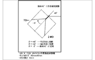
- the tear direction when the acute angle between the tear direction and the cutting line when the film is torn in the direction of 45 ° with the flow direction of the film is 45 ° is the flow direction or the width direction (see FIG. 1).
- the angle between the tearing direction and the cutting line is within the above range, there is a tendency that drilling can be performed while reducing the occurrence of burrs and the like, and there is a tendency that the straightness when cut by hand is excellent.
- the angle between the tear direction and the cutting line can be controlled by the stretching conditions during film production and the degree of orientation caused thereby.
- it tends to be torn in the direction in which the molecules are strongly oriented. That is, it is easy to tear in the MD and TD directions, and it is difficult to tear in the other direction, for example, 45 ° with respect to the MD direction. Therefore, even if it tears at 45 ° with the flow direction, it tears in the MD or TD direction.
- Such a film is a wound body wound around a core tube or the like, and when it is pulled out from here and cut by hand, a tension is applied in the pulling direction and a finger is bitten into the film to make a starting point for cutting. Then, it can be easily cut in the width direction of the wound body by propagating in the width direction from the starting point.
- the tear strength when tearing in the direction of 45 ° to the MD direction of the film is preferably 10 g or less, more preferably 1 to 8 g, and even more preferably 2 to 6 g. If the tear strength in the MD direction and the 45 ° direction is within the above range, the cutability in the MD direction and the TD direction tends to be excellent, and moreover, the generation of burrs and the like can be reduced and drilling can be performed. is there. If the tear strength is 10 g or less, it can be easily cut by hand.
- the tear strength when the film is torn in the direction of 45 ° with respect to the MD direction refers to the tear strength in the case where the tear test is performed in the same manner as the tear test B method (Elmendorf method) of JIS K 7128. Refers to the tear strength measured.
- the tear strength when the film is torn in the MD direction is preferably 10 g or less, more preferably 1 to 8 g, and even more preferably 2 to 6 g.
- the tear strength when the film is torn in the TD direction is preferably 10 g or less, more preferably 1 to 8 g, and even more preferably 2 to 6 g.
- the tear strength in the TD direction is within the above range, it tends to be superior in hand cutability in the TD direction, and there is a tendency that drilling can be performed while reducing the occurrence of burrs and the like. If the tear strength is greater than 10 g, it cannot be easily cut by hand.
- the thickness of the perforated plastic film is preferably 5.0 to 40.0 ⁇ m, more preferably 5.0 to 20.0 ⁇ m, and even more preferably 5.0 to 15.0 ⁇ m. If the thickness is 5.0 ⁇ m or more, it tends to be difficult to break. Moreover, it exists in the tendency for cut property to improve that thickness is 40 micrometers or less.
- the perforated plastic film of this embodiment may be laminated with another porous film, non-woven fabric or paper, or a functional layer such as an adhesive layer or a water repellent layer may be formed.
- a functional layer such as an adhesive layer or a water repellent layer
- the perforated plastic film is on the side in contact with the skin.
- the moisture permeability of the entire laminate preferably satisfies 300 to 3500 g / m 2 ⁇ 24 h.
- the perforated plastic film When used in skin protection applications, the perforated plastic film is cut to an appropriate size as necessary, and is applied to the skin so as to cover the wound generation part (or the part where the generation of the wound is to be prevented). It can be used by being fixed on the skin, for example, by overlaying and attaching with surgical tape. Alternatively, an ointment such as petrolatum may be applied to a wounded part of the skin (or a part where it is desired to prevent the occurrence of the wound), and the film may be placed thereon and applied using the adhesive effect of the ointment.
- an ointment such as petrolatum may be applied to a wounded part of the skin (or a part where it is desired to prevent the occurrence of the wound), and the film may be placed thereon and applied using the adhesive effect of the ointment.
- a laminate is prepared by laminating a film-like adhesive layer on the film cut to an appropriate size, and the wounded part of the skin (or the part where the occurrence of wounding is to be prevented) It can be used by being affixed to the skin so as to be within the frame of the adhesive layer.
- Manufacturing method of perforated plastic film Although there is no limitation in the manufacturing method of the perforated plastic film of this embodiment, it can manufacture by the manufacturing method of this embodiment including the process of preparing a base film, and a perforation process, for example.
- the manufacturing method of this embodiment may further have an electron beam crosslinking treatment step and / or a stretching treatment step as a part of the step of preparing the base film as an option.
- the step of preparing the base film is a step of preparing a base film as a raw material for the perforated plastic film of the present embodiment, and for example, a known film manufacturing method can be employed.
- This process includes, for example, a process of extruding a resin and a plasticizer from a circular die as a single layer or a multilayer raw material, a step of cooling and solidifying the extruded raw material, and a step of stretching the cooled and solid raw material.
- the stretching process is a known process in which stretching is performed in a uniaxial or biaxial direction with respect to the original film.
- the stretching method preferably biaxial stretching, more preferably sequential or simultaneous biaxial stretching method or inflation biaxial stretching method, among which the inflation biaxial stretching method is preferable. Biaxial stretching tends to improve cutability.
- the draw ratio in the MD and TD directions is preferably 5.0 to 12 times, more preferably 5.5 to 11 times, and even more preferably 6.0 to 10 times.
- the draw ratio is in the above range, the degree of orientation of the polymer compound constituting the film is increased, the film has excellent cutability by hand, and tearing trouble is suppressed (that is, tearing in the MD direction when tearing in the MD direction).
- tearing in the TD direction if the film is torn in the direction of 45 ° with respect to the MD direction, a film that is torn in either the MD direction or the TD direction tends to be obtained.
- the stretching ratio in the TD direction is a ratio of (film width after stretching) / (parison width before stretching), and the stretching ratio in the MD direction is (line speed after stretching) / (line speed before stretching). Is the ratio.
- the draw area ratio is preferably 5 to 70 times, and more preferably 20 to 60 times. When the stretched area ratio is 5 times or more, the cutting property tends to be more excellent. Moreover, it exists in the tendency for a stretched area magnification to become smaller than the dimensional change of a product because it is 70 times or less.
- the stretching temperature is preferably the melting point of the material constituting the film + 60 ° C. or less, more preferably the melting point + 40 ° C. or less, and further preferably the melting point + 30 ° C. or less. When the stretching temperature is in the above range, the degree of orientation of the polymer compound constituting the film is increased and the cutting property by hand tends to be excellent.
- the plastic film contains a polyethylene resin
- a crosslinking treatment by irradiating the parison or the stretched film with radiation.
- the radiation used in the radiation crosslinking treatment method is not particularly limited, and examples thereof include ionizing radiation such as ultraviolet rays, electron beams, X rays, ⁇ rays, ⁇ rays, ⁇ rays, and neutron rays.
- an electron beam is preferable.
- Examples of the irradiation method by electron beam irradiation include a method in which an electron beam is irradiated onto the entire parison or film with an energy voltage of 100 kV to 1 MV.
- the gel fraction determined in ASTM-D2765 of the treated film is preferably 10 to 60% by mass from the viewpoint of suppressing the occurrence of burrs and the like during perforation. Furthermore, when the crosslinking treatment is performed before stretching, it becomes possible to perform stretching at a high magnification, so that the polymer chains constituting the film become highly oriented by stretching at a high magnification, and the blade is used. The film can be easily cut by hand without doing.
- the gel fraction of the film is generally used as an index of the degree of crosslinking. If the gel fraction is increased, it becomes possible to stretch at a high magnification. On the other hand, if the gel fraction is too high, stretching tends to be difficult. Therefore, in this embodiment, the gel fraction is more preferably 15 to 50% by mass, and further preferably 25 to 40% by mass.
- the perforating process is a process of providing fine holes in the base film.
- a known method such as piercing with a hot needle or laser irradiation can be used.
- the average hole diameter can be adjusted by appropriately setting the diameter of the hot needle and the laser output according to the thickness and material of the film.
- the drilling conditions laser output, needle diameter, drilling density, etc.
- the hole diameter and hole density can be freely adjusted, and as a result, the aperture ratio can also be freely adjusted. Therefore, it is possible to easily design the moisture permeability of the perforated plastic film.
- a laser when a laser is used for perforation, when a substrate such as paper or film is laminated on the surface opposite to the film surface to be irradiated at the time of laser irradiation, perforation is performed by irradiation.
- the peripheral portion of the hole is preferably lightly bonded to the substrate, and the perforated portion can be processed without being thermally contracted and closed.
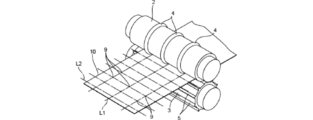
- a perforating apparatus including a pair of roll cutters having different cutting blade installation patterns as shown in FIGS. 2 and 3 may be used.
- the film 10 passing between the rolls is a portion where the cutting blade 4 provided on the roll 2 and the cutting blade 5 provided on the roll 3 intersect, That is, in the vicinity of the portion where the line L1 and the line L2 intersect in plan view, the pressure is applied simultaneously from the upper surface and the lower surface. For this reason, the film 10 is perforated at a portion 9 where the cutting edge 4 and the cutting edge 5 intersect to form a through hole.
- Perforation with such a roll cutter makes it easy to produce a perforated plastic film with a flat surface and a low coefficient of friction even after the hole is formed, because irregularities such as burrs and burrs are unlikely to occur at the end of the hole. can do.
- the perforated plastic film perforated with such a roll cutter has a flat surface, it is difficult to generate wrinkles and bumps even when wound into a roll, and the winding shape is good and winding marks are attached. However, a good product can be obtained.
- surface treatment such as corona treatment or plasma treatment, printing, or adhesive coating may be further performed.
- the perforated plastic film can be a wound body wound around a core tube.
- the handleability is good and a desired area can be easily cut out.
- the film is torn in the flow direction when tearing in the pulling direction, torn in the width direction when tearing in the width direction, and torn in the direction of 45 ° with respect to the pulling direction, the film is torn in either the pulling direction or the width direction.
- the acute angle between the tearing direction and the cutting line when tearing in the direction of 45 ° with the pulling direction is 30 to 60 °, and the tear strength when tearing in the direction of 45 ° with the pulling direction is 10 g or less.
- the film drawn from the wound body can be easily cut linearly by hand.
- the material of the core tube is not limited, and for example, paper, plastic, metal, or the like can be used.
- the core tube may be a hollow cylindrical object or a hollow cylindrical object.
- the other hand is used to apply tension to the direction of the film drawn by grasping the scroll by hand. It is preferable to use a thickness of 0.5 mm or more so that it can cope with the force (gripping force) applied when making the starting point of the cut with a finger.
- the diameter of the core tube is not limited, and can be, for example, 10 mm to 50 mm.
- Example 1 EXAMPLES Next, although an Example and a comparative example demonstrate this invention further in detail, this invention is not limited to this Example.
- moisture permeability, average pore diameter, aperture ratio, substantial aperture ratio, friction coefficient, gel fraction, oblique tearing, and thickness were measured by the following methods.
- the specimen was left at a position where the wind speed 10 mm above the test piece in a constant temperature / humidity device of 40 ⁇ 2 ° C. and 50 ⁇ 5% RH did not exceed 0.8 m / s, and the specimen after 8 hours.
- the weight change of was measured.
- the observation magnification is 100 times, the observation field of view is 1 cm square, and the field of view is set 5 cm inside from the edge of the first surface of the film (end in the MD direction).
- the hole diameters of all the openings were calculated, and the average value was obtained.
- the average value was calculated by measuring the same value in the same field of view at four points every 1 m in the MD direction (unwinding direction) of the film.
- the average pore diameter of the first surface of the film was averaged.
- the film was turned over, and the average pore diameter of the second surface was measured. And the smaller one of the average pore diameter of the first surface and the average pore diameter of the second surface was taken as the average pore diameter of the film.
- FIG. 1 shows an outline of an oblique tear test (tearability test in the MD direction and 45 ° direction) in the examples.
- the tear strength in the direction of 45 ° with respect to the MD direction of the base film is 45 ° from the MD direction by making a 1 cm cut into a 60 cm ⁇ 60 cm film using an Elmendorf tear strength tester (manufactured by Toyo Seiki) according to JISK7128. Measured according to JISK7128 except that the film was torn in the direction of.
- an acute angle between the actually teared direction and the tearing direction was measured.
- the cut property of the oblique tear test was evaluated by evaluating the acute angle formed between the tear direction and the tear direction (MD direction and 45 ° direction) according to the following evaluation criteria.
- ⁇ Evaluation criteria> A The acute angle formed by the tear direction and the tear direction is 40 to 50 °, and the tear strength is 2 to 6 g.
- ⁇ The acute angle formed by the tearing direction and the tearing direction is 30 ° or more and less than 40 °, or more than 50 ° and 60 ° or less, and the tear strength is 10 g or less.
- X The acute angle formed between the tearing direction and the tearing direction is more than 60 ° or less than 30 °, or the tear strength is more than 10 g.
- MD direction, TD direction tear test For the tear test in the MD direction and TD direction of the base film, an Elmendorf tear strength tester (manufactured by Toyo Seiki Co., Ltd.) is used according to JISK7128, and a 1 cm cut is made in a 60 cm ⁇ 60 cm film to tear in the MD direction and TD direction. Tests were conducted and evaluated according to the following criteria. ⁇ Evaluation criteria> ⁇ : The acute angle between the torn direction and the tearing direction is 15 ° or less. ⁇ : The acute angle between the torn direction and the tearing direction exceeds 15 °.
- the thickness of the film was measured according to ASTME-252. Specifically, the measurement was performed using TECLOCK US-26 manufactured by TECLOCK CORPORATION.
- LL ethylene-1-octene copolymer density 0.926 g / cm 3 MI 2.0 g / 10 min
- LD high pressure method low density polyethylene density 0.921 g / cm 3 MI 0.4 g / 10 min
- 70: 30 A material obtained by adding 0.5% by mass of glycerin monooleate to a polyethylene resin (composition) of a single-layer original fabric (Examples 1 and 4), a three-layer original fabric (Example 2), or 5 After extruding as a layer original (Example 3), it was cooled and solidified with cold water to produce a tubular original with a folding width of 120 mm and a thickness of 500 ⁇ m.
- Example 1 An electron beam irradiation apparatus, irradiated with an electron beam accelerated to 500 kV, and subjected to a crosslinking treatment so that the absorbed dose was 80 kGy.
- This is induced in a stretching machine, reheated, passed between two pairs of differential nip rolls, and bubbles are formed by air injection, MD direction is 8 times TD direction is 6 times (Examples 1 and 3), MD direction
- Example 2 An electron beam irradiation apparatus, irradiated with an electron beam accelerated to 500 kV, and subjected to a crosslinking treatment so that the absorbed dose was 80 kGy.
- Example 1 the obtained base film was irradiated with laser, and in Example 2, the hot needle was appropriately adjusted in the range of 135 to 170 ° C. in consideration of the gelation temperature and melting temperature of the resin. Then, perforation processing was performed to obtain a perforated plastic film. The average hole diameter was adjusted by adjusting the laser output in Examples 1 and 3 and the diameter of the hot needle in Example 2.
- Example 5 In the same manner as in Examples 1 and 3 (extruded as a single-layer original fabric and stretched in the MD direction 8 times and the TD direction 6 times), a pair of roll cutters 21 having different cutting blade installation patterns and A perforated plastic film was obtained by performing perforation using a roll cutter device 2 composed of 22.
- the roll cutter apparatus 2 used for FIG. 3 is shown.
- the roll cutter 21 and the roll cutter 22 are arranged to face each other with a cylindrical or columnar cutter.
- the axis of the roll cutter 21 and the axis of the roll cutter 22 are parallel to each other, and the roll cutter 21 and the roll cutter 22 are separated so as to sandwich the drilled object.
- Support portions 24 are provided at both ends of the roll cutter 21 in the axial direction, and the roll cutter 21 is supported by the frame 23 via the support portion 24 so as to be rotatable around the axis.
- Support portions 25 are provided at both ends of the roll cutter 22 in the axial direction, and the roll cutter 22 is supported by the frame 23 via the support portion 25 so as to be rotatable around the axis.
- the roll cutter 21 and the roll cutter 22 rotate in conjunction with each other, and the rotation direction C1 of the roll cutter 21 is opposite to the rotation direction C2 of the roll cutter 22.
- a cutting blade 211 is provided on the peripheral surface of the roll cutter 21.
- Cutting edge 211 is inclined at an angle theta 1 provided continuously in the circumferential direction with respect to the axial direction of the roll cutter 21, it is provided with a plurality at a pitch P1.
- a cutting blade 221 is provided on the peripheral surface of the roll cutter 22.
- the cutting blades 221 are continuously provided in the circumferential direction inclined at an angle ⁇ 2 with respect to the axial direction of the roll cutter 22, and a plurality of cutting blades 221 are provided at a pitch P 2.
- the cutting blade 211 and the cutting blade 221 are inclined in the same direction with respect to the axial direction.
- the cutting blade 211 and the cutting blade 221 are intermittently given with the pitch P1 and the pitch P2 in FIG. 2, they may be given in a spiral shape, for example.
- one end of the base film is sandwiched between the roll cutter 21 and the roll cutter 22 of the device 2 in the same manner as in the example shown in FIG. 2.
- the cutting blade 211 of the roll cutter 21 contacts the upper surface of the base film
- the cutting blade 221 of the roll cutter 22 contacts the lower surface of the base film.
- the base film is conveyed and processed along the longitudinal direction of the film.
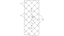
- the top view of the base film which passed between a pair of roll cutters 21 and 22 of the roll cutter apparatus 2 in FIG. 4 is shown.
- the cutting blade 211 is pressed against the upper surface of the base film, and a line L1 that is a trace of the cutting blade 211 is formed on the upper surface. Further, the cutting blade 221 is pressed against the lower surface of the base film, and a line L2 which is a trace of the cutting blade 221 is formed on the lower surface.
- Line L1 when viewed from the top side of the base film, extend in the longitudinal direction of the base film is inclined at an angle theta 1 with respect to the width direction of the base film, is formed with a plurality at a pitch P1.
- the line L2 When viewed from the lower surface side of the base film, the line L2 extends in the longitudinal direction of the base film inclined at an angle ⁇ 2 on the opposite side of the direction in which the line L1 is inclined with respect to the width direction of the base film, A plurality of pitches P2 are formed. In this way, the holes 11 are continuously formed in the base film at the portion where the cutting blade 211 and the cutting blade 221 intersect, and a perforated film is produced.
- PVDC vinylidene chloride-vinyl chloride copolymer
- Example 5 perforation processing was performed using the roll cutter device 2 to obtain a perforated plastic film.
- Example 7 LD (high pressure method low density polyethylene density 0.921 g / cm 3 MI 0.4 g / 10 min) was extruded into a cylindrical shape with a melt extruder to form bubbles and wound up to prepare a base film. Next, in the same manner as in Example 2, the hot needle was appropriately adjusted in the range of 135 to 170 ° C. to perform perforation processing to obtain a perforated plastic film.
- Example 8 Polypropylene was extruded with a melt extruder, cooled and solidified, then reheated, and biaxially stretched sequentially in the MD direction 4 times in the TD direction 8 times to obtain a base film.
- Example 9 A base film was prepared in the same manner as in Example 1 and bonded to an olefinic spunbonded nonwoven fabric at the time of laser irradiation, and perforated by laser irradiation in the same manner as in Example 1 to form a composite of the base film and the nonwoven fabric together with the perforation. Then, a perforated plastic film laminate was obtained.
- Example 10 A perforated plastic film was obtained in the same manner as in Example 5 except that the base film was extruded as a three-layer original and was stretched 6 times in the MD direction and 6 times in the TD direction.
- Example 11 A perforated plastic film was obtained in the same manner as in Example 5 except that the base film was extruded as a five-layer original.
- Example 12 Polyethylene terephthalate was extruded with a melt extruder and successively biaxially stretched to obtain a base film. In the same manner as in Example 5, a perforated plastic film was obtained by performing perforation using a roll cutter.
- Example 13 6 nylon was extruded with a melt extruder and biaxially stretched to obtain a base film. In the same manner as in Example 5, a perforated plastic film was obtained by performing perforation using a roll cutter.
- Example 14 In the same manner as in Example 1, a base film made of LL / LD was obtained. Next, in the same manner as in Example 2, the temperature of the hot needle was appropriately adjusted in the range of 135 to 170 ° C., and perforation was performed to obtain a perforated plastic film.
- a base film was obtained in the same manner as in Example 7. Next, a perforated plastic film was obtained by performing a perforating process by a porous process for pressure bonding to a protrusion described in Japanese Patent No. 1995281.
- Example 2 A tube-shaped original fabric was prepared in the same manner as in Example 1, and this was guided to an electron beam irradiation device, irradiated with an electron beam, and the absorbed dose was adjusted to perform a crosslinking treatment so that the gel fraction was 61% by mass. went. This was introduced into a stretching machine, reheated, passed between two pairs of differential nip rolls, and bubbles were formed by air injection. Films could not be collected because bubbles could not be formed. .
- Comparative Example 3 Polyethylene terephthalate was extruded with a melt extruder and successively biaxially stretched to obtain a base film. A hot needle was appropriately adjusted in the range of 150 to 220 ° C. in consideration of the gelation temperature and melting temperature of the resin, and perforated to give a perforated plastic film.
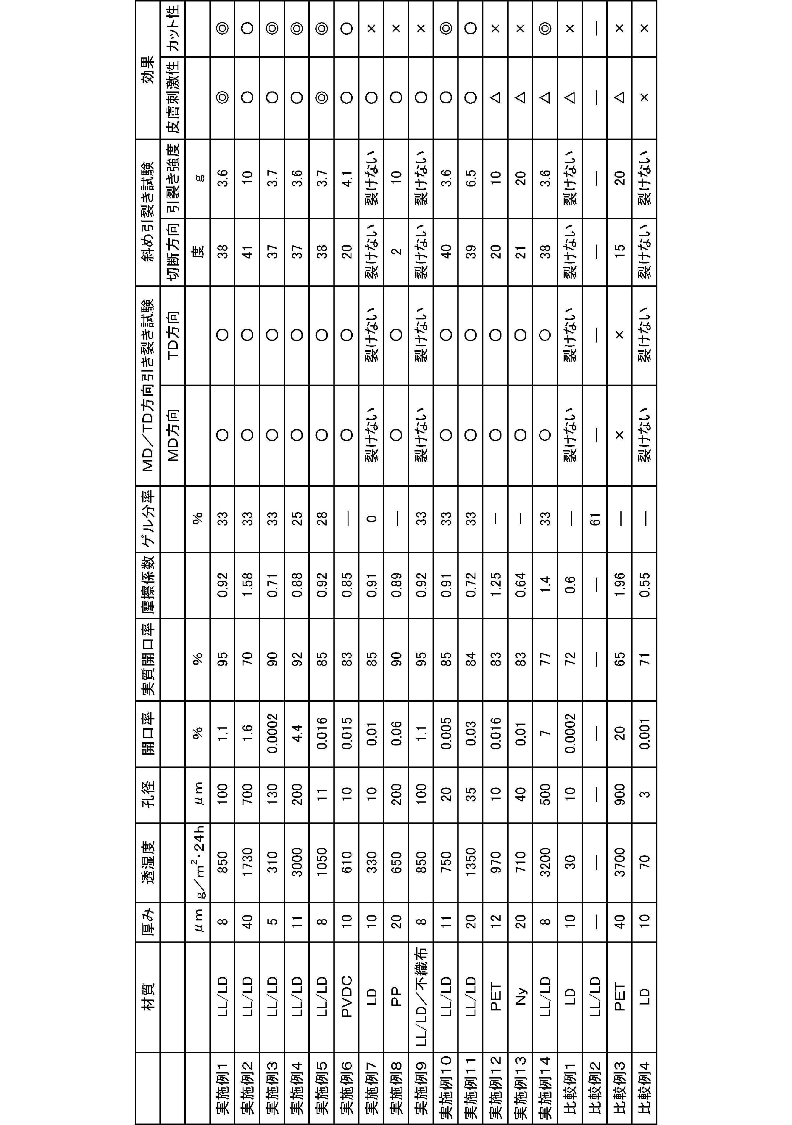
- Table 1 shows various physical properties of the perforated plastic films produced in Examples and Comparative Examples, and results of an oblique tear test and a skin irritation sensory test performed on the films.
- the plastic film for skin protection of the present invention can be suitably used for wound prevention, wound protection, wound treatment, and other uses for protecting the skin.
Landscapes
- Health & Medical Sciences (AREA)
- Animal Behavior & Ethology (AREA)
- Veterinary Medicine (AREA)
- Engineering & Computer Science (AREA)
- Public Health (AREA)
- General Health & Medical Sciences (AREA)
- Life Sciences & Earth Sciences (AREA)
- Heart & Thoracic Surgery (AREA)
- Vascular Medicine (AREA)
- Biomedical Technology (AREA)
- Epidemiology (AREA)
- Chemical & Material Sciences (AREA)
- Materials Engineering (AREA)
- Manufacture Of Porous Articles, And Recovery And Treatment Of Waste Products (AREA)
- Materials For Medical Uses (AREA)
- Laminated Bodies (AREA)
Abstract
Description
一方プラスチックフィルムは人の皮膚から蒸発する水分を適度に逃がすことが難しく、皮膚が蒸れて浸軟して脆弱化し、浸軟部が創傷を誘発するなどの問題を抱えている。このような問題を解決するため、透湿性を改善した多孔質フィルムが提案されている。
また、特許文献2においては、水蒸気透過性高分子材料と多孔性高分子材料からなる創傷被覆材用シート状素材が提案されており、空孔率40%以上の多孔質高分子材料を20μm以下のシリコーン層と組み合わせることで水蒸気透過性を130g/m2・hr以上とした旨の記載がある。
そして、このような多数の貫通孔を有するプラスチックフィルムの透湿度が300~3500g/m2・24hrであると皮膚刺激性が低く、皮膚保護用途にも用いることができることを見出し、本発明を完成させた。
[1]多数の貫通孔を有するプラスチックフィルムからなり、透湿度が300~3500g/m2・24hである、穿孔プラスチックフィルム。
[2]前記多数の貫通孔の平均孔径が5~300μmで、前記プラスチックフィルムの開口率が0.0003~4.5%である、[1]記載の穿孔プラスチックフィルム。
[3]前記多数の貫通孔の実質開口率が80~100%である[1]または[2]に記載の穿孔プラスチックフィルム。
[4]前記プラスチックフィルムの摩擦係数が1.7以下である[1]~[3]のいずれかに記載の穿孔プラスチックフィルム。
[5]前記プラスチックフィルムがポリエチレン系樹脂を含む、[1]~[4]いずれかに記載の穿孔プラスチックフィルム。
[6]前記プラスチックフィルムが、ゲル分率が10~60質量%であるポリエチレンからなる、[5]に記載の穿孔プラスチックフィルム。
[7]流れ方向引き裂き時には流れ方向に引き裂かれ、巾方向引き裂き時には巾方向に引き裂かれ、かつ流れ方向と45°の方向に引き裂いた場合は、流れ方向又は巾方向のいずれかの方向に引き裂かれる、[1]~[6]のいずれかに記載の穿孔プラスチックフィルム。
[8]流れ方向と45°の方向に引き裂いた場合の引き裂き方向と、切断線とのなす鋭角が30~60°であり、流れ方向と45°の方向に引き裂いた場合の引裂強度が10g以下である、[7]に記載の穿孔プラスチックフィルム。
[9]皮膚保護用である[1]~[8]のいずれかに記載の穿孔プラスチックフィルム。
[10]流れ方向引き裂き時には流れ方向に引き裂かれ、巾方向引き裂き時には巾方向に引き裂かれ、かつ流れ方向と45°の方向に引き裂いた場合は、流れ方向又は巾方向のいずれかの方向に、引き裂かれ、流れ方向と45°の方向に引き裂いた場合の引き裂き方向と、切断線とのなす鋭角が30~60°であり、流れ方向と45°の方向に引き裂いた場合の引裂強度が10g以下であるプラスチックフィルムを用意する工程と、
前記プラスチックフィルムに多数の孔を形成する穿孔加工工程
を含む、穿孔プラスチックフィルムの製造方法。
[11]前記プラスチックフィルムを用意する工程が、前記プラスチックフィルムを電子線架橋する工程を含む、[10]に記載の穿孔プラスチックフィルムの製造方法。
[12]不織布と[1]~[8]のいずれかに記載の穿孔プラスチックフィルムとを含む複合体。
[13]芯管と、該芯管に巻回された[1]~[8]のいずれかに記載の穿孔プラスチックフィルムとを含む、巻回体。
(穿孔プラスチックフィルム)
本発明の穿孔プラスチックフィルムは、多数の貫通孔を有する透湿度が300~3500g/m2・24hのプラスチックフィルムである。
ここでいう透湿度とは、後述する透湿度試験方法を用いて、40℃、湿度50%においてフィルムを通過する水蒸気の質量を測定し、得られた測定値を該フィルム1m2・24時間当たりに換算した値をいう。
また、多数の貫通孔とは、10~40000コ/100cm2とする。
これに対して、本発明において採用する透湿度は、通常の外気環境下(40℃、湿度50%)においてサンプルを通過する水蒸気の質量を測定するものであって、その測定環境が皮膚保護フィルムの実際の使用状況と類似しているので、皮膚保護用途のフィルムの特性(浸軟や乾燥のしにくさ)を評価するのに適している。そして、本発明者らが鋭意検討したところ、プラスチックフィルムの透湿度を300~3500g/m2・24hという範囲内に設定すると、人の皮膚から蒸発する水分を適度に逃がし、蒸れて浸軟したり、逆に乾燥し過ぎることなく、さらに後述する皮膚や創傷部の上をフィルムが滑る際の摩擦による物理的な刺激低減やカット性を損なうことなく皮膚刺激性を抑えることができることが分かった。
透湿度は、より好ましくは、300~2000g/m2・24hでありこの範囲に設定すると、さらに皮膚の水分状態を適度に保ち皮膚刺激性を抑えることができる。さらに好ましくは300~1800g/m2・24h、最も好ましくは600~1700g/m2・24hである。
透湿度は、フィルムの材質や厚み、並びに、開口率いずれによって調整してもよい。
開口率によって透湿度を調整すると、水蒸気透過度以外の特性も考慮してフィルム材料を選択することができ、フィルム材料の選択の自由度が高くなるという点で好ましい。
本発明において、「孔径」とはフィルム平面上の開口部の直径を意味するが、開口部は必ずしも真円とは限らないので、本発明においては、「孔径」とは、開口部を真上から(フィルム面に平行に視野を設定して)光学顕微鏡で観察したときの画像における開口部の面積と同一面積を有する真円の直径(円相当径)を意味するものとする。なお、開口部内において穿孔不良があった場合、その不良部も開口部とみなす。
孔径を測定する際の画像処理に用いる機器やソフトには特に制限はなく公知のものを用いることができる。本実施形態においては、以下のようにしてフィルムの平均孔径を測定することができる。
光学顕微鏡(例えば、キーエンス社VHX-900)で、観察倍率100倍、観察視野を1cm角に設定する。
まず、フィルムの第一面について任意の5か所の視野を選択する。そして、各視野について、視野内の全開口部の孔径を測定しその平均値を算出するという作業を5回繰り返し、得られた5つ平均値の平均をさらに算出し、第一面の平均孔径とする。
次いで、フィルムをひっくり返して、第二面についても同様に任意の5か所の視野を選択し、5つの視野の平均値の平均をさらに算出し、第二面の平均孔径とする。
第一面と第二面の平均孔径のうち、小さい方の値をフィルムの平均孔径とする。
平均孔径は、より好ましくは5~250μmであり、さらに好ましくは7~200μmであり、最も好ましくは10~150μmである。
本実施形態において、フィルムの開口率は平均孔径と同様に以下のようにして測定することができる。
フィルムの第一面と第二面のうち平均孔径の小さかった方の面について、任意の5か所の視野を選択する。そして、各視野について、視野内の全開口部の面積を測定しその平均値を算出すると共に、同視野内の開口部の個数をカウントし、開口部の面積の平均値と開口部個数を掛け合わせて開口面積を算出する。この作業を5回繰り返し、これら5点の開口面積の総和を視野の総面積5cm2で割り返し、フィルムの開口率とする。
なお、開口率は、フィルムに穿孔する貫通孔の平均孔径や穿孔密度を調整することにより所望の値とすることができる。
本実施形態において、実質開口率は次のようにして測定することができる。
フィルムの第一面と第二面のうち平均孔径の小さかった方の面について、任意の5か所の視野を選択する。そして各視野について視野内の全開口部について、開口部分における完全な貫通部のみの面積(以下、「実質開口面積」という。)を測定する。この際、穿孔不良部の面積は実質開口面積に含まない。そして視野内の全開口部の実質開口面積の合計を全開口部の面積の合計で割り返した値の平均値を算出し、これを実質開口率とする。
ここでいう摩擦係数とは、後述の試験方法を用いて、人工皮膚の上を速度1000m/minで走行距離80mmを滑らせたときの動摩擦係数の値をいう。摩擦係数が当該範囲であれば、皮膚や創傷部の上をフィルムが滑る際の摩擦による物理的な刺激を低減し、皮膚に直接接触させたり、貼付したりしても問題がないほどに皮膚刺激性を抑えることができる。
摩擦係数は、より好ましくは1.3以下、なお好ましくは1.2以下、さらに好ましくは1.0以下である。
上記摩擦係数を1.7以下とすることによる皮膚刺激性低減効果は、透湿度が、特に700~1500g/m2・24h、さらには800~1400g/m2・24h、とりわけ900~1300g/m2・24h、さらにとりわけ1000~1200g/m2・24hである場合に、より顕著に奏される。
この点について、本発明者らが鋭意検討したところ、以下のような知見a~cが得られた。
a.直交する二方向に高延伸されたプラスチックフィルムはバリ等を発生させることなく穿孔加工しやすい。
具体的には、流れ方向引き裂き時には流れ方向に引き裂かれ、巾方向引き裂き時には巾方向に引き裂かれ、かつ流れ方向と45°の方向に引き裂いた場合は、流れ方向又は巾方向のいずれかの方向に引き裂かれるようなプラスチックフィルムは、バリ等を発生させることなく穿孔加工しやすい。
特に、プラスチックフィルムが、流れ方向と45°の方向に引き裂いた場合の引き裂き方向と、切断線とのなす鋭角が30~60°であり、流れ方向と45°の方向に引き裂いた場合の引裂強度が10g以下であると、よりバリ等の発生は低く抑えられる。
b.プラスチックフィルムが、ポリエチレン系樹脂を含み、かつ、ゲル分率(ASTM-D2765)が10~60質量%であるものであると、バリ等を発生させることなく穿孔加工しやすい。
c.穿孔加工方法として、例えば、後述する一対のロールカッターやレーザーを用いた方法を採用すると、バリ等の発生が少ない。
したがって、上記a~cに挙げた条件を適宜組み合わせる(すなわち、a~cに挙げた条件のうちのいずれか一つを採用したり、いずれか二つを組み合わせて採用したり、或いは、全てを採用する)ことによって、多数の貫通孔を有し、しかも、摩擦係数が1.7以下である穿孔プラスチックフィルムを製造することができる。特に、条件cを採用することが効果的であり、これに加えてさらに条件a、bのいずれかを採用することがより好ましく、条件cに加えて条件a、bの両方を組み合わせることがさらに好ましい。
このようなポリエチレン系樹脂としては、特に限定されないが、例えば、ポリエチレン;エチレン-酢酸ビニル共重合体;エチレン-アクリル酸共重合体、エチレン-メタクリル酸共重合体等のエチレン-脂肪族不飽和カルボン酸共重合体;エチレン-メチルアクリレート共重合体、エチレン-メチルメタクリレート共重合体、エチレン-エチルアクリレート共重合体、エチレン-エチルメタクリレート共重合体、エチレン-ブチルアクリレート共重合体、エチレン-ブチルメタクリレート共重合体等のエチレン-脂肪族不飽和カルボン酸エステル共重合体等が挙げられる。
これらは、1種単独で用いても、2種以上を併用してもよい。
これらは1種単独で用いても又は2種以上を併用してもよい。
ゲル分率は、架橋度の指標として一般に用いられている値であり、ゲル分率を10~60質量%とするには、フィルムを構成する高分子化合物を架橋させればよい。架橋方法に限定はなく、例えば、架橋剤を使用してもよいし、フィルムに対して放射線架橋(電子線架橋)を行うことによってゲル分率を調整することもできる。放射線架橋は、架橋剤を使用する化学的架橋と異なり、フィルムを構成する高分子化合物を架橋剤を介さず直接的に架橋させることができるので、添加剤を添加することなく架橋させることができ、皮膚刺激性を抑えるという点で好ましい。
具体的には、流れ方向(フィルム製膜時のMD方向)引き裂き時には流れ方向に引き裂かれ、巾方向(流れ方向と直交する方向、TD方向)引き裂き時には巾方向に引き裂かれ、かつ流れ方向と45°の方向に引き裂いた場合は、流れ方向又は巾方向のいずれかの方向に引き裂かれるものであることが好ましい。
このような特性を有するプラスチックフィルムは、バリ等をあまり発生させることなく穿孔加工することができるので、その結果、摩擦係数の低い穿孔プラスチックフィルムとすることができ、さらに、穿孔プラスチックフィルムをカット面が直線的になるように手で任意の寸法にカットすることも可能となる。
ここで、「流れ方向に引き裂かれる」、「巾方向に引き裂かれる」とは、各々、流れ方向、又は、巾方向と切断線(切断した方向)のなす鋭角が0~15°であることをいい、「切断線」とは、引き裂き開始点と終了点(フィルム試験片の端辺と実際に引き裂かれた線の交点)を結ぶ線をいう。流れ方向、又は、幅方向と切断線のなす鋭角は、0~10°であることがより好ましく、0~5°であることがさらに好ましい。
ここで、試験片の大きさは60×60mm、スリット長さは10mmとし、フィルムの流れ方向と45°の方向への引き裂き評価の場合は、試験片はフィルムの原反から流れ方向と45°の方向で採取する。
なお、フィルムの引き裂き評価の結果は、穿孔加工前後において実質的に変わりはないが、本実施形態においては、穿孔プラスチックフィルム(穿孔後)について定義されるものとする。
引き裂き方向と切断線の角度が上記範囲内であると、バリ等の発生を低減して穿孔加工することができる傾向にあり、しかも、手でカットした場合の直進性により優れる傾向にある。
MD方向と45°の方向の引裂強度が上記範囲内であると、MD方向及びTD方向のカット性により優れる傾向にあり、しかも、バリ等の発生を低減して穿孔加工することができる傾向にある。なお、引裂強度が10g以下であると、手により容易にカットすることができる。
ここで、フィルムのMD方向と45°の方向に引き裂いた場合の引裂強度とは、JIS K 7128の引裂試験B法(エルメンドルフ法)と同様にして引き裂き試験を行った場合において、引き裂かれた際に測定される引裂強度をいう。
フィルムのTD方向に引き裂いた場合の引裂強度は、10g以下が好ましく、1~8gがより好ましく、2~6gがさらに好ましい。TD方向の引裂強度が上記範囲内であると、TD方向の手によるカット性により優れる傾向にあり、バリ等の発生を低減して穿孔加工することができる傾向にある。なお、引裂強度が10gより大きいと、手により容易にカットすることができない。
本実施形態の穿孔プラスチックフィルムは、別の多孔性フィルムや不織布や紙と積層したり、粘着層や撥水層などの機能層を設けるなどして積層体を構成するようにしてもよい。皮膚保護用途に用いる場合には、穿孔プラスチックフィルムを皮膚に接する側とすることが好ましい。
また、この場合、積層体全体の透湿度もまた、300~3500g/m2・24hを満たすことが好ましい。
穿孔プラスチックフィルムは、皮膚保護用途に用いる場合、必要に応じて適切な大きさに切断し、創傷発生部(または、創傷の発生を予防したい部分)の上を被覆した状態になるように皮膚上に重ね、サージカルテープ等で貼り付けるなどして皮膚上に固定して使用できる。また、ワセリンなどの軟膏を皮膚の創傷発生部(または、創傷の発生を予防したい部分)に塗布し、その上から該フィルムをのせて、軟膏の粘着効果を利用して貼付してもよい。
別法としては、適切な大きさに切断した該フィルムに枠状の粘着層を積層した積層体を作成し、皮膚の創傷発生部(または、創傷の発生を予防したい部分)が該枠状の粘着層の枠内に入るように皮膚に貼り付けて使用することができる。
本実施形態の穿孔プラスチックフィルムの製造方法に限定はないが、例えば、ベースフィルムを用意する工程と穿孔加工工程とを含む本実施形態の製造方法によって製造することができる。本実施形態の製造方法は、さらにオプションとして、ベースフィルムを用意する工程の一部として、電子線架橋処理工程及び/または延伸処理工程を有していてもよい。
延伸処理工程は、フィルム原反に対して一軸または二軸方向に延伸処理を行う公知の工程である。延伸方法に限定はなく、好ましくは2軸延伸、より好ましくは逐次または同時2軸延伸法又はインフレーション2軸延伸法を採用することができ、この中でもインフレーション2軸延伸法が好ましい。2軸延伸をすることでカット性がより向上する傾向にある。
また、延伸面積倍率は、5~70倍が好ましく、20~60倍がより好ましい。延伸面積倍率が、5倍以上であることによりカット性により優れる傾向にある。また、延伸面積倍率が、70倍以下であることにより製品の寸法変化より小さくなる傾向にある。
延伸温度は、フィルムを構成する材料の融点+60℃以下が好ましく、融点+40℃以下がより好ましく、融点+30℃以下がさらに好ましい。延伸温度が上記範囲であることにより、フィルムを構成する高分子化合物の配向度が高くなり手によるカット性により優れる傾向にある。
さらに、延伸前に架橋処理を行った場合には、高倍率での延伸を行うことが可能になるため、高倍率での延伸により、フィルムを構成する高分子鎖が高配向となり、刃物を利用することなく容易に手でフィルムを切れるようにすることができる。
フィルムのゲル分率は、一般に、架橋度の指標として用いられる。ゲル分率を高めると高倍率での延伸が可能となるが、一方でゲル分率があまり高くなりすぎると逆に延伸が困難になる傾向にある。そのため、本実施形態においてゲル分率は、15~50質量%がより好ましく、25~40質量%がさらに好ましい。
平均孔径は、熱針の径やレーザー出力を、フィルムの厚みや材料に合わせて適宜設定することにより調整できる。
本実施形態においては、穿孔加工工程における穿孔条件(レーザー出力、針径、穿孔密度等)を制御することで、孔径や孔密度を自由に調整でき、その結果、開口率もまた自由に調整できるので、穿孔プラスチックフィルムの透湿度の設計が容易にできる。
なお、本実施形態において、穿孔にレーザーを用いる場合には、レーザー照射の際に、照射するフィルム面とは反対側の面に、紙やフィルムといった基材を積層しておくと、照射により穿孔した孔の周縁部が基材に軽接着し、穿孔部が熱収縮して塞がることなく加工することができるため好ましい。
例えば、図2に示された穿孔装置においては、ロールの間を通過するフィルム10は、ロール2上に設けられた切刃4とロール3上に設けられた切刃5とが交差する部分、つまり平面視で線L1と線L2とが交差する部分の近傍において、上面及び下面から同時に加圧される。このため、フィルム10は切刃4と切刃5とが交差する部分9において穿孔され、貫通孔が形成される。
このようなロールカッターによる穿孔によれば、孔の端部にバリ及びカエリ等の凹凸が生じにくいため、孔が形成された後もフラットな表面を有する摩擦係数の低い穿孔プラスチックフィルムを簡単に製造することができる。
また、このようなロールカッターで穿孔された穿孔プラスチックフィルムは、フラットな表面を有するため、ロール状に巻き取ってもシワ及びコブ等が生じづらく、巻き姿が良好であると共に、巻き痕が付かず、良好な製品が得られる。
また、芯管の直径に限定はなく、例えば10mm~50mmとすることができる。
次に、実施例及び比較例によって本発明を更に詳細に説明するが、本発明はこの実施例に限定されるものではない。実施例及び比較例に於いて、透湿度、平均孔径、開口率、実質開口率、摩擦係数、ゲル分率、斜め引裂き、厚みは以下の方法で測定した。
JIS1099繊維製品の透湿度試験方法A-2法ウォーター法と同じ測定装置を使用して、以下の手順で評価した。
あらかじめ40℃に温めた直径60mm深さ25mmのアルミ製カップに40℃の精製水30mlを入れ、直径70mmの試験片を、後述する平均孔径の小さい方の面を水側に向けて、カップに対して同心円になるように乗せ、パッキン及びリングを装着し、ちょうナットで固定して試験体とした。この試験体を40±2℃、50±5%RHの恒温・恒湿装置内の試験片上の10mm上部の風速が0.8m/sを超えない位置に静置し、8時間後の試験体の重量変化を測定した。下記式にて透湿度を算出した。
透湿度(g/m2・24h)=〔重量変化(g)/透湿面積(m2)〕×3
光学顕微鏡(キーエンス社VHX-900)で観察の倍率100倍、観察の視野は1cm角とし、フィルムの第一面の端(MD方向の端)から5cm内側のところに視野を設定し、当該視野内のすべての開口部の孔径を算出し、その平均値を求めた。
さらに、前記視野からフィルムのMD方向(巻出方向)に1mおきに4点のところで、同様の視野で同じく測定してそれぞれ平均値を算出し、最終的にはこれら5点の平均値をさらに平均して、そのフィルムの第一面の平均孔径とした。
同様にしてフィルムをひっくり返して、第二面の平均孔径を測定した。そして、第一面の平均孔径と第二面の平均孔径のうち、小さい方の値をフィルムの平均孔径とした。
上記平均孔径と同様の方法で、フィルムの第一面と第二面のうち平均孔径の小さかった方の面について、光学顕微鏡で1cm角の視野を設定し、この視野内のすべての開口部の面積を測定してその平均値を算出すると共に、同視野内の開口部の個数をカウントし、前記平均値と開口部個数を掛け合わせて開口面積を算出した。
フィルムのMD方向に1mおきに計5つの視野を設定し、同様の操作を実施して各視野の開口面積を算出し、これら5点の開口面積の総和を視野の総面積5cm2で割り返し、フィルムの開口率とした。
上記平均孔径と同様の方法で、フィルムの第一面と第二面のうち平均孔径の小さかった方の面について、光学顕微鏡で1cm角の視野を設定し、視野内のすべての開口部について、開口部の面積と開口部分における完全な貫通部のみの面積(実質開口面積)を測定し、各々の合計を算出した。この際、穿孔不良部の面積は実質開口面積に含まないようにした。
フィルムのMD方向に1mおきに計5つの視野を設定し、同様の操作を実施して、各視野について実質開口面積の合計を開口部の面積の合計で割り返した値を求め、その平均値を算出した。
株式会社東洋精機製作所friction tester(TR-2)を用いて、長さ100mm×巾64mm重さ200gの摩擦面発泡体の金属製ライダーに、測定する穿孔フィルム(長さ100mm×巾64mm)を貼り付け、人工皮膚であるバイオスキンプレートノーマル(長さ195mm×巾130mm)(株式会社ビューラックス製)上を速度1000m/minで走行距離80mmを滑らせ、動摩擦係数を測定した。
ASTM-D2765に準拠し以下のように測定した。
沸騰パラキシレン中にフィルムを12時間浸漬した後の不溶分の質量分率を次式により表示したものをゲル分率とした。尚、試料は、延伸されたフィルムを140℃で熱収縮させてパリソン状に戻したものを使用した。
ゲル分率(質量%)=(浸漬後の試料質量/浸漬前の試料質量)×100
図1に実施例における斜め引き裂き試験(MD方向と45°の方向の引き裂き性試験)の概略を示す。
ベースフィルムのMD方向と45°の方向の引裂強度は、JISK7128に準じたエルメンドルフ引裂強度試験機(東洋精機製)を用いて、60cm×60cmのフィルムに1cmの切れ目を入れてMD方向から45°の方向に引き裂いたこと以外は、JISK7128に準じて測定した。
上記斜め引裂試験の測定において、実際に引き裂かれた方向と引き裂き方向(MD方向と45°の方向)とのなす鋭角を測定した。
斜め引裂試験のカット性評価は、引き裂かれた方向と引き裂き方向(MD方向と45°の方向)とのなす鋭角を下記評価基準により評価することにより行なった。
<評価基準>
◎:引き裂かれた方向と引き裂き方向とのなす鋭角が40以上50°以下、かつ引裂強度が2~6gである。
○:引き裂かれた方向と引き裂き方向とのなす鋭角が30°以上40°未満、又は、50°超過60°以下かつ引裂強度が10g以下である。
×:引き裂かれた方向と引き裂き方向とのなす鋭角が60°超過又は30°未満である、又は引裂強度が10g超過である。
ベースフィルムのMD方向及びTD方向の引裂試験は、JISK7128に準じてエルメンドルフ引裂強度試験機(東洋精機製)を用いて、60cm×60cmのフィルムに1cmの切れ目を入れてMD方向及びTD方向に引裂き試験を行い、下記の基準で評価した。
<評価基準>
○:引き裂かれた方向と引き裂き方向とのなす鋭角が15°以下
×:引き裂かれた方向と引き裂き方向とのなす鋭角が15°超
フィルムの厚みは、ASTME-252に準じて測定した。具体的には、TECLOCKCORPORATION製 TECLOCK US-26を使用して測定を行った。
フィルムを5cm角に切り出し、サージカルテープを用いて健常な皮膚の被験者20人の上腕部皮膚へ貼り付け、24時間経過後に剥離し、30分放置後にフィルムが接触していた皮膚の様子を下記のように判定した。
<評価基準>
◎浸軟、かゆみなどの違和感なしが19人以上かつ発赤者なし
○浸軟、かゆみなどの違和感なしが16人~18人かつ発赤者なし
△浸軟、かゆみなどの違和感なしが10人~15人かつ発赤者なし
×浸軟、かゆみなどの違和感なしが9人以下、若しくは発赤1人以上
LL(エチレン-1-オクテン共重合体 密度0.926g/cm3 MI2.0g/10分):LD(高圧法低密度ポリエチレン 密度0.921g/cm3 MI0.4g/10分)=70:30のポリエチレン系樹脂(組成物)に、グリセリンモノオレートを0.5質量%添加したものを環状ダイより単層原反(実施例1、4)、3層原反(実施例2)、又は5層原反(実施例3)として押出した後、冷水にて冷却固化して、折り巾120mm、厚さ500μmのチューブ状原反を作製した。
これを電子線照射装置に誘導し、500kVに加速した電子線を照射し、吸収線量として80kGyになるように架橋処理を行った。
これを延伸機内に誘導して再加熱を行い、2対の差動ニップロール間に通して、エアー注入によりバブルを形成し、MD方向8倍TD方向6倍(実施例1、3)、MD方向6倍TD方向6倍(実施例2)の延伸条件でそれぞれ延伸を行いダブルプライフィルムを得た。さらに実施例1、3、4については、スリット工程でシングルフィルムに剥いで各ベースフィルムを得た。
得られたベースフィルムに、実施例1、3、4おいてはレーザー照射で、実施例2においては熱針を樹脂のゲル化温度、溶融温度を考慮して135~170℃の範囲で適宜調整し、穿孔加工を施して、穿孔プラスチックフィルムを得た。
なお、平均孔径は、実施例1及び3においてはレーザーの出力を、実施例2においては熱針の径を調整することにより調整した。
実施例1、3と同様にして(ただし、単層原反として押出し、MD方向8倍TD方向6倍に延伸)得られたベースフィルムに、切り刃の設置パターンの異なる一対のロールカッター21及び22からなるロールカッター装置2を用いて穿孔加工を施して穿孔プラスチックフィルムを得た。
図3に使用したロールカッター装置2を示す。
ロールカッター装置2において、ロールカッター21及びロールカッター22は、円筒状または円柱状のカッターで互いに対向して配置されている。ロールカッター21の軸とロールカッター22の軸とは互いに平行であって、ロールカッター21とロールカッター22とは、被穿孔物を挟み込める程度に離間している。ロールカッター21の軸方向の両端には支持部24が設けられており、ロールカッター21は支持部24を介して軸回りに回転可能にフレーム23に支持されている。ロールカッター22の軸方向の両端には支持部25が設けられており、ロールカッター22は支持部25を介して軸回りに回転可能にフレーム23に支持されている。ロールカッター21とロールカッター22とは連動して回転し、ロールカッター21の回転方向C1は、ロールカッター22の回転方向C2と反対である。
ロールカッター21の周面には、切刃211が設けられている。切刃211は、ロールカッター21の軸方向に対して角度θ1で傾斜して周方向に連続して設けられ、ピッチP1で複数設けられている。ロールカッター22の周面には、切刃221が設けられている。切刃221は、ロールカッター22の軸方向に対して角度θ2で傾斜して周方向に連続して設けられ、ピッチP2で複数設けられている。切刃211及び切刃221は、軸方向に対して同じ方向に傾いている。なお、切刃211及び切刃221は、図2においてはピッチP1、及びピッチP2で間欠的に施されているが、例えばらせん状に施されていても良い。
このようなロールカッター装置2を使用し、図2に示される例と同様にして、ベースフィルムの一端を装置2のロールカッター21及びロールカッター22の間に挟み込む。このとき、ロールカッター21の切刃211はベースフィルムの上面に当接し、ロールカッター22の切刃221はベースフィルムの下面に当接する。この状態で、ロールカッター21とロールカッター22とを連動して回転させることにより、ベースフィルムをフィルムの長手方向に沿って搬送して加工する。
図4にロールカッター装置2の一対のロールカッター21及び22の間を通ったベースフィルムの平面図を示す。ロールカッター装置2では、ベースフィルムの上面に切刃211が押し当てられて、切刃211の跡である線L1が上面に形成される。また、ベースフィルムの下面に切刃221が押し当てられて、切刃221の跡である線L2が下面に形成される。線L1は、ベースフィルムの上面側から見た場合、ベースフィルムの幅方向に対して角度θ1で傾斜してベースフィルムの長手方向に延びており、ピッチP1で複数形成される。線L2は、ベースフィルムの下面側から見た場合、ベースフィルムの幅方向に対して線L1が傾斜する方向とは反対側に角度θ2で傾斜してベースフィルムの長手方向に延びており、ピッチP2で複数形成される。
このようにして、切刃211と切刃221とが交差する部分において、ベースフィルムに孔11が連続して形成され、穿孔フィルムが作製される。
塩化ビニリデン-塩化ビニル共重合体PVDC(塩化ビニリデン単量体単位含有量/塩化ビニル単量体単位含有量=80質量%/20質量%、質量平均分子量12万)100質量部に対し、脂肪酸エステル類としてジブチルセバケートを3質量部、アセチルトリブチルシトレートを4質量部、エポキシ化化合物としてエポキシ化大豆油を2質量部、添加してヘンシェルミキサーで5分混合した。得られた混合物を溶融押出機で管状に押出し、約10℃の冷水槽で過冷却後、35℃の水中に通し、延伸温度30℃、MD方向に3.0倍、TD方向に4.0倍のインフレーション2軸延伸を行って得た管状フィルムをピンチロールで折りたたみ、厚み10μmの平坦長尺状のベースフィルムを得た。
実施例5と同様にロールカッター装置2を用いて穿孔加工を施して穿孔プラスチックフィルムを得た。
LD(高圧法低密度ポリエチレン 密度0.921g/cm3 MI0.4g/10分)を溶融押出機で筒状に押出してバブルを形成して巻き取り、ベースフィルムを作製した。
次いで、実施例2と同様に熱針を135~170℃の範囲で適宜調整して穿孔加工を施して穿孔プラスチックフィルムを得た。
[実施例8]
ポリプロピレンを溶融押出機で押出し冷却固化後、再加熱し、MD方向4倍TD方向8倍に逐次2軸延伸を行いベースフィルムを得た。
次いで、実施例2と同様に熱針の温度を180~220℃の範囲で適宜調整し、穿孔加工を施して穿孔プラスチックフィルムを得た。
[実施例9]
実施例1と同様にしてベースフィルムを作成し、レーザー照射時にオレフィン系スパンボンド不織布と貼り合わせ、実施例1と同様にレーザー照射により穿孔加工を施して、穿孔と共ににベースフィルムと不織布との複合化を行い、穿孔プラスチックフィルム積層体を得た。
ベースフィルム製造時に3層原反として押出し、MD方向6倍TD方向6倍に延伸した以外は実施例5と同様にして、穿孔プラスチックフィルムを得た。
ベースフィルム製造時に5層原反として押出した以外は実施例5と同様にして、穿孔プラスチックフィルムを得た。
ポリエチレンテレフタレートを溶融押出機で押出し、逐次2軸延伸を行いベースフィルムを得た。実施例5と同様にロール状カッターを用いて穿孔加工を施して穿孔プラスチックフィルムを得た。
6ナイロンを溶融押出機で押出し、2軸延伸してベースフィルムを得た。実施例5と同様にロール状カッターを用いて穿孔加工を施して穿孔プラスチックフィルムを得た。
実施例1と同様にして、LL/LDからなるベースフィルムを得た。
次いで、実施例2と同様に熱針の温度を135~170℃の範囲で適宜調整し、穿孔加工を施して穿孔プラスチックフィルムを得た。
[比較例1]
実施例7と同様の方法でベースフィルムを得た。
次いで、特許1995281号明細書に記載される突起物へ圧着するポーラス加工により穿孔加工を施して穿孔プラスチックフィルムを得た。
[比較例2]
実施例1と同様にしてチューブ状原反を作成し、これを電子線照射装置に誘導して電子線を照射し、吸収線量を調整してゲル分率が61質量%となるよう架橋処理を行った。
これを延伸機内に誘導して再加熱を行い、2対の差動ニップロール間に通して、エアー注入によりバブルを形成したところ、バブルを形成することができずにフィルム採取が不可能であった。
[比較例3]
ポリエチレンテレフタレートを溶融押出機で押出し、逐次2軸延伸を行いベースフィルムを得た。熱針を樹脂のゲル化温度、溶融温度を考慮して150~220℃の範囲で適宜調整し、穿孔加工を施して穿孔プラスチックフィルムを得た。
低密度ポリエチレン(密度0.921g/cm3 MI0.4g/10分)を溶融押出機で筒状に押出してバブルを形成して巻き取り、ベースフィルムを作製した。次いで、特許1995281号明細書に記載される突起物へ圧着するポーラス加工により穿孔加工を施して穿孔プラスチックフィルムを得た。
具体的には、絆創膏、創傷被覆材、ドレッシング材、包帯、サージカルテープ、閉鎖密閉療法用フィルム、熱傷用ラップ、手術用被覆保護材、褥瘡予防フィルム、けい皮吸収材用フィルム、患者識別用リストバンド用フィルム、テーピング剤、サポーター、留置針固定用フィルム、パッチ試験用フィルム等として使用することができる。
Claims (13)
- 多数の貫通孔を有するプラスチックフィルムからなり、透湿度が300~3500g/m2・24hである、穿孔プラスチックフィルム。
- 前記多数の貫通孔の平均孔径が5~300μmで、
前記プラスチックフィルムの開口率が0.0003~4.5%である、
請求項1記載の穿孔プラスチックフィルム。 - 前記多数の貫通孔の実質開口率が80~100%である請求項1または2に記載の穿孔プラスチックフィルム。
- 前記プラスチックフィルムの摩擦係数が1.7以下である請求項1~3のいずれか1項に記載の穿孔プラスチックフィルム。
- 前記プラスチックフィルムがポリエチレン系樹脂を含む、請求項1~4いずれか1項に記載の穿孔プラスチックフィルム。
- 前記プラスチックフィルムが、ゲル分率が10~60質量%であるポリエチレンからなる、請求項5に記載の穿孔プラスチックフィルム。
- 流れ方向引き裂き時には流れ方向に引き裂かれ、巾方向引き裂き時には巾方向に引き裂かれ、かつ流れ方向と45°の方向に引き裂いた場合は、流れ方向又は巾方向のいずれかの方向に引き裂かれる、請求項1~6のいずれか1項に記載の穿孔プラスチックフィルム。
- 流れ方向と45°の方向に引き裂いた場合の引き裂き方向と、切断線とのなす鋭角が30~60°であり、
流れ方向と45°の方向に引き裂いた場合の引裂強度が10g以下である、
請求項7に記載の穿孔プラスチックフィルム。 - 皮膚保護用である請求項1~8のいずれか1項に記載の穿孔プラスチックフィルム。
- 流れ方向引き裂き時には流れ方向に引き裂かれ、巾方向引き裂き時には巾方向に引き裂かれ、かつ流れ方向と45°の方向に引き裂いた場合は、流れ方向又は巾方向のいずれかの方向に、引き裂かれ、流れ方向と45°の方向に引き裂いた場合の引き裂き方向と、切断線とのなす鋭角が30~60°であり、流れ方向と45°の方向に引き裂いた場合の引裂強度が10g以下であるプラスチックフィルムを用意する工程と、
前記プラスチックフィルムに多数の孔を形成する穿孔加工工程
を含む、穿孔プラスチックフィルムの製造方法。 - 前記プラスチックフィルムを用意する工程が、前記プラスチックフィルムを電子線架橋する工程を含む、請求項10に記載の穿孔プラスチックフィルムの製造方法。
- 不織布と請求項1~8のいずれか1項に記載の穿孔プラスチックフィルムとを含む複合体。
- 芯管と、該芯管に巻回された請求項1~8のいずれか1項に記載の穿孔プラスチックフィルムとを含む、巻回体。
Priority Applications (4)
| Application Number | Priority Date | Filing Date | Title |
|---|---|---|---|
| CN201580057688.XA CN107073160A (zh) | 2014-11-12 | 2015-11-11 | 穿孔塑料膜 |
| US15/519,852 US20170239093A1 (en) | 2014-11-12 | 2015-11-11 | Perforated Plastic Film |
| JP2016559083A JP6363729B2 (ja) | 2014-11-12 | 2015-11-11 | 穿孔プラスチックフィルム |
| EP15858670.1A EP3219334B1 (en) | 2014-11-12 | 2015-11-11 | Perforated plastic film |
Applications Claiming Priority (4)
| Application Number | Priority Date | Filing Date | Title |
|---|---|---|---|
| JP2014229488 | 2014-11-12 | ||
| JP2014-229490 | 2014-11-12 | ||
| JP2014229490 | 2014-11-12 | ||
| JP2014-229488 | 2014-11-12 |
Publications (1)
| Publication Number | Publication Date |
|---|---|
| WO2016076346A1 true WO2016076346A1 (ja) | 2016-05-19 |
Family
ID=55954425
Family Applications (1)
| Application Number | Title | Priority Date | Filing Date |
|---|---|---|---|
| PCT/JP2015/081695 Ceased WO2016076346A1 (ja) | 2014-11-12 | 2015-11-11 | 穿孔プラスチックフィルム |
Country Status (5)
| Country | Link |
|---|---|
| US (1) | US20170239093A1 (ja) |
| EP (1) | EP3219334B1 (ja) |
| JP (1) | JP6363729B2 (ja) |
| CN (1) | CN107073160A (ja) |
| WO (1) | WO2016076346A1 (ja) |
Cited By (2)
| Publication number | Priority date | Publication date | Assignee | Title |
|---|---|---|---|---|
| JP2018187901A (ja) * | 2017-05-11 | 2018-11-29 | スリーエム イノベイティブ プロパティズ カンパニー | 伸縮材、伸縮材の製造方法、伸縮性部材、伸縮性部材の製造方法、及び衣料製品 |
| EP3486195A4 (en) * | 2016-07-12 | 2019-08-28 | Asahi Kasei Kabushiki Kaisha | CONTAINER FOR RECEIVING A ADHESIVE ADHESIVE FILM, DEVICE WITH ADHESIVE FILM AND INFECTIVE FILM |
Families Citing this family (1)
| Publication number | Priority date | Publication date | Assignee | Title |
|---|---|---|---|---|
| CN116135141A (zh) * | 2021-11-18 | 2023-05-19 | 霍尼韦尔国际公司 | 用于出血检测的装置和方法 |
Citations (8)
| Publication number | Priority date | Publication date | Assignee | Title |
|---|---|---|---|---|
| JPS62148246A (ja) * | 1985-12-23 | 1987-07-02 | Oji Yuka Gouseishi Kk | 有孔樹脂フイルムの製造方法 |
| JPH042499A (ja) * | 1990-04-20 | 1992-01-07 | Norito Sudo | 樹脂フィルムの穿孔装置および穿孔方法 |
| JPH0586216A (ja) * | 1991-09-27 | 1993-04-06 | Tonen Chem Corp | 多孔性プラスチツクフイルムの製造方法 |
| JP2002519117A (ja) * | 1998-06-30 | 2002-07-02 | キンバリー クラーク ワールドワイド インコーポレイテッド | 局所的濡れ性を持つ穿孔フィルム・カバー及びその製造方法 |
| JP2005178365A (ja) * | 2003-11-12 | 2005-07-07 | Tredegar Film Products Corp | 複合弾性織物 |
| JP2007089493A (ja) * | 2005-09-29 | 2007-04-12 | Mitsubishi Chem Mkv Co | 農業用フィルム |
| WO2012096020A1 (ja) * | 2011-01-12 | 2012-07-19 | 株式会社江東彫刻 | 穿孔装置、穿孔方法、被穿孔物 |
| JP2014237810A (ja) * | 2013-05-09 | 2014-12-18 | 旭化成パックス株式会社 | 穿孔フィルム |
Family Cites Families (7)
| Publication number | Priority date | Publication date | Assignee | Title |
|---|---|---|---|---|
| US3171830A (en) * | 1962-06-19 | 1965-03-02 | Grace W R & Co | Crosslinking process |
| GB1537036A (en) * | 1975-04-22 | 1978-12-29 | Ici Ltd | Core for use in reeling up sheet materials |
| US4499896A (en) * | 1982-03-30 | 1985-02-19 | Minnesota Mining And Manufacturing Co. | Reservoir wound dressing |
| US5759467A (en) * | 1996-03-08 | 1998-06-02 | Minnesota Mining And Manufacturing Company | Method for making multilayer polyester film |
| US6635334B1 (en) * | 2000-08-08 | 2003-10-21 | 3M Innovative Properties Company | Cloth-like polymeric films |
| DE102010001702A1 (de) * | 2009-12-03 | 2011-06-09 | Evonik Degussa Gmbh | Perforierte Folie |
| KR101787801B1 (ko) * | 2010-07-12 | 2017-10-18 | 데이고꾸세이약꾸가부시끼가이샤 | 3층구조의 지지체 및 이를 이용한 수성 패치제 |
-
2015
- 2015-11-11 US US15/519,852 patent/US20170239093A1/en not_active Abandoned
- 2015-11-11 WO PCT/JP2015/081695 patent/WO2016076346A1/ja not_active Ceased
- 2015-11-11 EP EP15858670.1A patent/EP3219334B1/en not_active Not-in-force
- 2015-11-11 CN CN201580057688.XA patent/CN107073160A/zh active Pending
- 2015-11-11 JP JP2016559083A patent/JP6363729B2/ja active Active
Patent Citations (8)
| Publication number | Priority date | Publication date | Assignee | Title |
|---|---|---|---|---|
| JPS62148246A (ja) * | 1985-12-23 | 1987-07-02 | Oji Yuka Gouseishi Kk | 有孔樹脂フイルムの製造方法 |
| JPH042499A (ja) * | 1990-04-20 | 1992-01-07 | Norito Sudo | 樹脂フィルムの穿孔装置および穿孔方法 |
| JPH0586216A (ja) * | 1991-09-27 | 1993-04-06 | Tonen Chem Corp | 多孔性プラスチツクフイルムの製造方法 |
| JP2002519117A (ja) * | 1998-06-30 | 2002-07-02 | キンバリー クラーク ワールドワイド インコーポレイテッド | 局所的濡れ性を持つ穿孔フィルム・カバー及びその製造方法 |
| JP2005178365A (ja) * | 2003-11-12 | 2005-07-07 | Tredegar Film Products Corp | 複合弾性織物 |
| JP2007089493A (ja) * | 2005-09-29 | 2007-04-12 | Mitsubishi Chem Mkv Co | 農業用フィルム |
| WO2012096020A1 (ja) * | 2011-01-12 | 2012-07-19 | 株式会社江東彫刻 | 穿孔装置、穿孔方法、被穿孔物 |
| JP2014237810A (ja) * | 2013-05-09 | 2014-12-18 | 旭化成パックス株式会社 | 穿孔フィルム |
Non-Patent Citations (1)
| Title |
|---|
| See also references of EP3219334A4 * |
Cited By (3)
| Publication number | Priority date | Publication date | Assignee | Title |
|---|---|---|---|---|
| EP3486195A4 (en) * | 2016-07-12 | 2019-08-28 | Asahi Kasei Kabushiki Kaisha | CONTAINER FOR RECEIVING A ADHESIVE ADHESIVE FILM, DEVICE WITH ADHESIVE FILM AND INFECTIVE FILM |
| JP2018187901A (ja) * | 2017-05-11 | 2018-11-29 | スリーエム イノベイティブ プロパティズ カンパニー | 伸縮材、伸縮材の製造方法、伸縮性部材、伸縮性部材の製造方法、及び衣料製品 |
| JP7065570B2 (ja) | 2017-05-11 | 2022-05-12 | スリーエム イノベイティブ プロパティズ カンパニー | 伸縮材、伸縮材の製造方法、伸縮性部材、伸縮性部材の製造方法、及び衣料製品 |
Also Published As
| Publication number | Publication date |
|---|---|
| JPWO2016076346A1 (ja) | 2017-06-08 |
| CN107073160A (zh) | 2017-08-18 |
| EP3219334B1 (en) | 2019-05-08 |
| EP3219334A1 (en) | 2017-09-20 |
| US20170239093A1 (en) | 2017-08-24 |
| EP3219334A4 (en) | 2017-09-20 |
| JP6363729B2 (ja) | 2018-07-25 |
Similar Documents
| Publication | Publication Date | Title |
|---|---|---|
| DE3344334C2 (de) | Folienverband | |
| TW583093B (en) | Three-dimensional highly elastic film/non-woven composite, and method for forming same | |
| RU2176187C2 (ru) | Многослойная воздухопроницаемая пленка и способ ее изготовления | |
| CN100358587C (zh) | 用于粘贴绷带的粘性膜和使用所述粘性膜的粘贴绷带 | |
| TWI495442B (zh) | 化妝品浸漬片及其製造方法 | |
| US20120172777A1 (en) | Stabilized foam for medical psa substrate | |
| JP2023101615A (ja) | 伸張可能な手当用品 | |
| JP5285356B2 (ja) | 貼付剤 | |
| JP6363729B2 (ja) | 穿孔プラスチックフィルム | |
| JP2004130079A5 (ja) | ||
| TW393401B (en) | Apertured films having durable wettability and process for making them | |
| CN118876379A (zh) | 微孔透气膜和制造该微孔透气膜的方法 | |
| CN110167391A (zh) | 具有可溶性膜的阻隔贴片 | |
| CN110177536A (zh) | 具有可溶性膜的阻隔贴片和改善皮肤外观的方法 | |
| US20140349053A1 (en) | Multi-Layered Assembly With Tight Peel Control | |
| JP2013255856A (ja) | 貼付体シート | |
| KR20160026976A (ko) | 상처 드레싱 | |
| JP5033602B2 (ja) | 貼付剤用複合不織布 | |
| JP4153751B2 (ja) | 医療用粘着テープ及びその製造方法 | |
| US20130164495A1 (en) | Patch backing for water-based pasty preparation | |
| KR20200126358A (ko) | 반창고 및 반창고용 폴리우레탄 부직포 | |
| JP4551084B2 (ja) | 支持体及びそれを用いた貼付剤 | |
| JP2019025078A (ja) | ドレナージ用穿孔プラスチックフィルム | |
| JP3203717U (ja) | 透湿耐水性を有する易引裂性複合層構造 | |
| EP1140490A1 (en) | Breathable elastic laminates |
Legal Events
| Date | Code | Title | Description |
|---|---|---|---|
| 121 | Ep: the epo has been informed by wipo that ep was designated in this application |
Ref document number: 15858670 Country of ref document: EP Kind code of ref document: A1 |
|
| ENP | Entry into the national phase |
Ref document number: 2016559083 Country of ref document: JP Kind code of ref document: A |
|
| WWE | Wipo information: entry into national phase |
Ref document number: 15519852 Country of ref document: US |
|
| REEP | Request for entry into the european phase |
Ref document number: 2015858670 Country of ref document: EP |
|
| NENP | Non-entry into the national phase |
Ref country code: DE |