WO2016076378A1 - 無線制御装置、端末装置および通信方法 - Google Patents
無線制御装置、端末装置および通信方法 Download PDFInfo
- Publication number
- WO2016076378A1 WO2016076378A1 PCT/JP2015/081804 JP2015081804W WO2016076378A1 WO 2016076378 A1 WO2016076378 A1 WO 2016076378A1 JP 2015081804 W JP2015081804 W JP 2015081804W WO 2016076378 A1 WO2016076378 A1 WO 2016076378A1
- Authority
- WO
- WIPO (PCT)
- Prior art keywords
- communication
- radio
- terminal device
- terminal
- base station
- Prior art date
- Legal status (The legal status is an assumption and is not a legal conclusion. Google has not performed a legal analysis and makes no representation as to the accuracy of the status listed.)
- Ceased
Links
Images







Classifications
-
- H—ELECTRICITY
- H04—ELECTRIC COMMUNICATION TECHNIQUE
- H04W—WIRELESS COMMUNICATION NETWORKS
- H04W76/00—Connection management
- H04W76/10—Connection setup
- H04W76/14—Direct-mode setup
-
- H—ELECTRICITY
- H04—ELECTRIC COMMUNICATION TECHNIQUE
- H04W—WIRELESS COMMUNICATION NETWORKS
- H04W16/00—Network planning, e.g. coverage or traffic planning tools; Network deployment, e.g. resource partitioning or cells structures
- H04W16/14—Spectrum sharing arrangements between different networks
-
- H—ELECTRICITY
- H04—ELECTRIC COMMUNICATION TECHNIQUE
- H04W—WIRELESS COMMUNICATION NETWORKS
- H04W24/00—Supervisory, monitoring or testing arrangements
- H04W24/10—Scheduling measurement reports ; Arrangements for measurement reports
-
- H—ELECTRICITY
- H04—ELECTRIC COMMUNICATION TECHNIQUE
- H04W—WIRELESS COMMUNICATION NETWORKS
- H04W72/00—Local resource management
- H04W72/04—Wireless resource allocation
-
- H—ELECTRICITY
- H04—ELECTRIC COMMUNICATION TECHNIQUE
- H04W—WIRELESS COMMUNICATION NETWORKS
- H04W72/00—Local resource management
- H04W72/04—Wireless resource allocation
- H04W72/044—Wireless resource allocation based on the type of the allocated resource
- H04W72/0446—Resources in time domain, e.g. slots or frames
-
- H—ELECTRICITY
- H04—ELECTRIC COMMUNICATION TECHNIQUE
- H04W—WIRELESS COMMUNICATION NETWORKS
- H04W72/00—Local resource management
- H04W72/04—Wireless resource allocation
- H04W72/044—Wireless resource allocation based on the type of the allocated resource
- H04W72/0453—Resources in frequency domain, e.g. a carrier in FDMA
-
- H—ELECTRICITY
- H04—ELECTRIC COMMUNICATION TECHNIQUE
- H04W—WIRELESS COMMUNICATION NETWORKS
- H04W72/00—Local resource management
- H04W72/20—Control channels or signalling for resource management
- H04W72/23—Control channels or signalling for resource management in the downlink direction of a wireless link, i.e. towards a terminal
-
- H—ELECTRICITY
- H04—ELECTRIC COMMUNICATION TECHNIQUE
- H04W—WIRELESS COMMUNICATION NETWORKS
- H04W92/00—Interfaces specially adapted for wireless communication networks
- H04W92/16—Interfaces between hierarchically similar devices
- H04W92/18—Interfaces between hierarchically similar devices between terminal devices
-
- H—ELECTRICITY
- H04—ELECTRIC COMMUNICATION TECHNIQUE
- H04W—WIRELESS COMMUNICATION NETWORKS
- H04W76/00—Connection management
- H04W76/20—Manipulation of established connections
- H04W76/23—Manipulation of direct-mode connections
Definitions
- the present invention relates to a radio control apparatus, a terminal apparatus, and a communication method, and more specifically, to a radio control apparatus, a terminal apparatus, and a communication method for performing direct communication between terminal apparatuses in a radio communication system. It is.
- E-UTRAN Evolved Universal Terrestrial Radio Access Network
- UE User Equipment
- D2D communication Device to Device Communication
- D2D communication is executed using a part of radio resources used for uplink of cellular communication such as LTE, for example. It is said that the distance between terminal devices to which D2D communication can be applied is about several hundred meters.
- 3GPP (3rd Generation Partnership Project) Release 12 a method of detecting a terminal in the vicinity of a terminal device and a method of broadcasting data to an unspecified terminal device have been proposed (for example, Non-Patent Document 1). Or see 2.)
- the present invention has been made in view of such a problem, and an object thereof is to provide a radio control device, a terminal device, and a communication method that realize high continuity of communication between terminals.
- a radio control apparatus is a radio control apparatus that controls inter-terminal communication in which radio communication is performed directly between a plurality of terminal apparatuses without using a base station apparatus.
- a control unit that allocates a frequency band that is not supported by the control unit as a radio resource that can be used for inter-terminal communication, and a radio communication unit that transmits resource information regarding the radio resource allocated by the control unit to the terminal device.
- the wireless communication unit may transmit the resource information through a broadcast channel.
- the radio communication unit may transmit information on frequency resources and / or information on time resources as resource information.
- the wireless communication unit may further transmit information on one or more service types that are permitted in the communication between terminals using the wireless resource allocated by the control unit.
- the radio control apparatus is a concept including, for example, E-UTRAN, including a base station apparatus or a host apparatus thereof.
- control unit may allocate radio resources for each terminal device, and the radio communication unit may transmit resource information specifying the radio resources allocated for each terminal device using an individual channel.
- the radio communication unit receives radio resource measurement information reported from the terminal device after allocating radio resources for each terminal device in the control unit, and the control unit, based on the measurement information from the terminal device, It is determined whether or not to switch the allocated radio resource, and when it is determined that switching should be performed, switching information regarding switching is generated, and the wireless communication unit transmits the switching information generated by the control unit to the terminal device. May be.
- the radio communication unit receives radio resource measurement information reported from the terminal device after allocating radio resources to the terminal device in the control unit, and the control unit allocates based on the measurement information from the terminal device.
- control unit may allocate a radio resource to be used for the service type based on the service type that is performed in the inter-terminal communication and requested from the terminal device.
- a terminal apparatus is a terminal apparatus that performs inter-terminal communication that directly performs wireless communication between a plurality of terminal apparatuses without going through the base station apparatus, and is supported in the base station apparatus
- a communication unit that receives resource information that specifies a frequency band that is not used as a radio resource that can be used for inter-terminal communication, and determines whether or not the terminal device supports the radio resource specified by the resource information. If not, perform inter-terminal communication using radio resources. If not, it is supported by the base station device and can be used for inter-terminal communication.
- a control unit that executes communication between terminals using radio resources.
- the terminal device when the terminal device supports the radio resource specified by the resource information, the terminal device can continuously execute the inter-terminal communication using the radio resource. Moreover, an unused band can be used effectively and the use of radio resources for cellular communication can be saved.
- a communication method includes a radio control apparatus that controls inter-terminal communication that directly performs radio communication between a plurality of terminal apparatuses and not via a base station apparatus.
- the radio control apparatus allocates frequency information that is not supported by the base station apparatus as radio resources that can be used for communication between terminals, and specifies resource information that specifies the allocated radio resources.
- the terminal device receives the resource information, determines whether the terminal device supports the radio resource specified by the resource information, and if so, uses the radio resource. If this is not supported, radio resources that can be used for inter-terminal communication within the frequency band supported by the base station device are And use to perform communication between terminals.
- the present invention it is possible to provide a radio control device, a terminal device, and a communication method that realize high continuity of communication between terminals and enable effective use of radio resources.
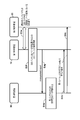
- FIG. 3 is a sequence diagram illustrating an operation example of the wireless communication system according to the first embodiment. It is a figure which shows an example of the frequency band designator for D2D. It is a figure which shows an example of the resource allocation designator of a time direction. 3 is a flowchart illustrating an operation example of the terminal device according to the first embodiment;
- FIG. 3 is a diagram illustrating a configuration example of a wireless communication system according to a second embodiment.
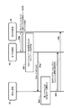
- FIG. 10 is a sequence diagram illustrating an operation example of the wireless communication system according to the second embodiment. It is a sequence diagram which shows an example of the band transition process concerning Example 2.
- FIG. It is a sequence diagram which shows an example of the band transition process concerning Example 2.
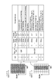
- FIG. 10 is a diagram illustrating an example of D2D resource allocation in the third embodiment.
- FIG. 10 is a sequence diagram illustrating an operation example of the wireless communication system according to the third embodiment.
- FIG. 10 is a sequence diagram illustrating an operation example of the wireless communication system according to the third embodiment.
- the present invention relates to D2D communication technology in which terminal devices directly perform wireless communication.
- the radio control apparatus allocates a frequency band that is not supported by the base station apparatus as radio resources that can be used for D2D communication, and transmits resource information specifying the allocated radio resources to the terminal apparatus.
- the terminal device receives the resource information, the terminal device determines whether the terminal device is compatible with the radio resource specified by the resource information. If the terminal device is compatible, the terminal device uses the radio resource to If communication is not performed and the communication is not supported, communication between terminals is performed using radio resources that can be used for communication between terminals within the frequency band supported by the base station apparatus.
- the base station Normally, in order for a terminal device to perform communication in a cellular system, the base station needs to be deployed in an area where the terminal device exists. However, installation of a base station requires various procedures and is a very expensive operation.
- the above-described D2D communication technique is a technique for performing direct communication between the terminal devices without using a base station. The implementation of this D2D communication does not necessarily require the presence of a base station, and thus can be realized without the installation cost of the base station as described above.
- the cost of installing the base station is very high, it is very difficult to expand a base station with a small area covered by one base station such as a small cell throughout the country. For this reason, for example, even when there is a band (frequency band) that can be used exclusively for a small cell, the band cannot be used for communication in an area where the small cell is not expanded. If the above-described D2D communication technique is used, communication using the band is possible, but there is no way for the terminal device to know that the band can be used for D2D communication. Moreover, although it is possible by the prior art to use the said band as an independent ad hoc band, there also existed a subject that communication cannot be continued when the said band becomes unusable also in this case .
- the present invention solves the above-described problems, enables a dynamic radio resource change from the radio network side, and appropriately manages a band for performing communication between terminals. Thereby, it is possible to provide communication between terminals while maintaining high communication continuity, and furthermore, it is possible to effectively use radio resources.
- FIG. 1 is a diagram illustrating a configuration example of a wireless communication system according to an embodiment of the present invention.
- the radio communication system 100 includes a first terminal apparatus 10, a second terminal apparatus 20, and a base station apparatus (E-UTRAN) 30 that configures an LTE radio access network.
- E-UTRAN base station apparatus
- the base station device 30 supports the band f1 for cellular communication.
- the first terminal apparatus 10 and the second terminal apparatus 20 are located in the cell area of the band f1, and can perform cellular communication with the base station apparatus 30 using the band f1.
- the first terminal device 10 and the second terminal device 20 are terminals that can perform inter-terminal communication (D2D communication) that does not pass through the base station device 30 by using radio resources in the band f1.
- D2D communication inter-terminal communication
- the first terminal apparatus 10 and the second terminal apparatus 20 are in the RRC_CONNECTED state with respect to the base station apparatus 30.
- the RRC_CONNECTED state refers to a state in which radio resources are managed by the base station apparatus and the terminal apparatus can transmit and receive data. Functions such as data transmission / reception and feedback of information such as CQI (Channel Quality Indicator) to the base station apparatus are provided. It is ready to run.
- CQI Channel Quality Indicator
- the base station device 30 sends a notification (resource information) that permits use of radio resources in the band f2 that is not supported by the base station for D2D communication to the first terminal device 10 and It can be transmitted to the second terminal device 20.
- the first terminal device 10 and the second terminal device 20 can perform D2D communication with the counterpart terminal device using the radio resource in the band f2.
- an unused band can be used effectively and the use of radio resources for cellular communication can be saved.
- “supported / not supported” includes not having a communication function for the band, and also includes having a communication function but not being allowed to use the band. .
- any of the 1st terminal device 10 and the 2nd terminal device 20 should just be a RRC_CONNECTED state with respect to the base station apparatus 30.
- FIG. For example, only the first terminal apparatus 10 receives a notification permitting the radio resource in the band f2 to be used for D2D communication from the base station apparatus 30, and the first terminal apparatus 10 replaces the base station apparatus 30 with the second terminal. It is also possible to notify the device 20 that the band f2 is available. The same applies to each embodiment described below.
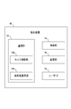
- FIG. 2 is a diagram illustrating a configuration example of terminal devices used as the first terminal device 10 and the second terminal device 20 of FIG.
- the terminal device includes a communication unit 12, a control unit 14, a storage unit 16, and a user interface (user IF) 18.
- user IF user interface
- the communication unit 12 includes a cellular communication unit 122 and an inter-terminal communication unit 124.
- the cellular communication unit 122 performs wireless communication with the base station device 30.
- the inter-terminal communication unit 124 directly uses the radio resource for D2D communication allocated by the base station apparatus, and does not pass through the base station apparatus 30 with the terminal apparatus that is the partner of D2D communication. To communicate. For these communication processes, known modulation / demodulation techniques and antenna techniques may be used.
- the storage unit 16 stores data transmitted from the base station device 30 or the D2D communication counterpart terminal device, and transmits the data to the base station device 30 or the D2D communication counterpart terminal device through the user IF 18.
- the obtained data may be stored.
- the user IF 18 may include a screen interface, an input interface that receives input from a user such as operation buttons and a touch panel, and an image capturing unit such as a camera.
- the control unit 14 is configured by a CPU, for example, and comprehensively controls each unit using information received from the cellular communication unit 122 or the terminal-to-terminal communication unit 124 or information stored in the storage unit 16.
- the control unit 14 designates the terminal device with the resource information. It is determined whether it corresponds to the radio resource of the band f2.
- the control unit 14 supports the band f2 the inter-terminal communication unit 124 controls the execution of the D2D communication with the counterpart terminal device using the radio resource of the band f2.
- the band f1 The D2D communication can be executed using the wireless resources.
- the control unit 14 uses the radio signal received by the cellular communication unit 122 to measure the downlink radio quality for each cell in the base station device 30 and surrounding base station devices. Moreover, the control part 14 may measure the radio
- RSRP Reference Signal Received Power
- RSRQ Reference Signal Received Quality
- ID identifier
- FIG. 3 is a diagram illustrating a configuration example of the base station apparatus 30 of FIG.
- Base station apparatus 30 includes a communication unit 32, a control unit 34, and a storage unit 36.
- the communication unit 32 includes a wireless communication unit 322 and a network communication unit 324.
- the wireless communication unit 322 uses the information stored in the storage unit 36 while the control unit 34 uses a predetermined cellular method with each of the first terminal device 10 and the second terminal device 20 belonging to the cell area of the local station. To perform cellular wireless communication.
- the network communication unit 324 performs inter-base station communication with another adjacent base station apparatus via the X2 interface or the like.
- the storage unit 36 stores, for example, TDD config information acquired from another adjacent base station device via the network communication unit 324.
- the radio communication unit 322 transmits resource information related to the radio resource allocated by the control unit 34 to the terminal device.
- This resource information may be transmitted by broadcast using a broadcast channel, or may be transmitted toward a specific terminal device using a dedicated channel. Further, the resource information may include information on frequency resources and / or information on time resources.
- the radio communication unit 322 receives the measurement information related to the radio quality reported from the terminal device after the control unit 34 assigns the radio resource to each terminal device, and generates the control unit 34 based on the measurement information.
- the switched information may be transmitted to the terminal device.
- the wireless communication unit 322 may further transmit information on one or more service types that are permitted in the communication between terminals using the wireless resource allocated by the control unit 34. Details of the service type will be described later.
- the control unit 34 notifies the first terminal device 10 and the second terminal device 20 of a radio resource that can be used for D2D communication in the band f1 supported by the base station device 30 by a control message or the like. Furthermore, the control unit 34 allocates the band f2 that is not supported by the base station device 30 as a radio resource that can be used for D2D communication, and sets resource information that specifies the allocated radio resource to the first terminal device 10 and the second terminal device. 20 can be transmitted. This resource information can be broadcasted via a broadcast channel to terminal devices located in the cell area of the band f1. In addition, the control unit 34 may allocate radio resources in the band f2 for each terminal device, and transmit resource information specifying the radio resources allocated for each terminal device using an individual channel.
- control unit 34 determines whether or not to switch the assigned radio resource based on the measurement information reported from the terminal device. If it is determined that the switching should be performed, the control unit 34 may generate switching information regarding the switching. Good. The switching information may include information regarding the switching destination radio resource. Further, the control unit 34 may assign a radio resource to be used for the service type based on the service type that is performed in the inter-terminal communication and requested from the terminal device.
- switching may be replaced with terms such as “change”, “correction”, “transition”, “migration”, “replacement”, “alternative”, “replacement”, “setting”, and “resetting”.
- QCI QoS Class Identifier
- the base station apparatus 30 stores information related to QCI (QCI table) in the storage unit 36 in advance.
- the control unit 34 can allocate radio resources in the band f2 or the band f1 based on a quality of service (QoS) class (QCI) required for D2D communication.
- QoS quality of service
- Resource information includes, for example, band information that can be used for D2D communication, frequency resource area within the band, EARFCN (E-UTRAN absolute radio frequency channel number), bandwidth of D2D radio resources, system frame number, and retransmission control Format setting channel (PHICH) setting information, or downlink bandwidth, or any combination of the above information may be included.
- band information that can be used for D2D communication
- frequency resource area within the band EARFCN (E-UTRAN absolute radio frequency channel number), bandwidth of D2D radio resources, system frame number, and retransmission control Format setting channel (PHICH) setting information, or downlink bandwidth, or any combination of the above information may be included.
- EARFCN E-UTRAN absolute radio frequency channel number
- bandwidth of D2D radio resources bandwidth of D2D radio resources
- system frame number system frame number
- PHICH retransmission control Format setting channel
- Example 1 A first embodiment of the present invention will be described with reference to FIGS.
- the first terminal device 10 and the second terminal device 20 exist in the cell area of the band f ⁇ b> 1 supported by the base station device 30.
- radio resources that can be used for D2D communication in the cell area of the band f1 the band information of the band f2 that is not supported by the base station, the frequency resource region in the band f2, or both Is included in the broadcast channel from the base station device 30 of the cell and notified to the first terminal device 10 and the second terminal device 20.
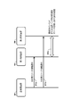
- FIG. 4 is a sequence diagram illustrating an operation example of the wireless communication system according to the first embodiment.
- the base station device 30 includes resource information (D2D resource information) that designates a band f2 that is not supported by the base station as a radio resource that can be used for D2D communication in a SIB (System Information Block). Then, broadcast notification is made to the first terminal device 10 and the second terminal device 20 (S1a, S1b).
- D2D resource information designates a band f2 that is not supported by the base station as a radio resource that can be used for D2D communication in a SIB (System Information Block).
- SIB System Information Block
- the resource information for D2D is band information that can be used for D2D communication, a frequency resource region in the band, a bandwidth of a radio resource for D2D, a system frame number, or a retransmission control format designation channel (PHICH) setting information, or downlink bandwidth, or any combination of the above information.
- band information that can be used for D2D communication
- a frequency resource region in the band a bandwidth of a radio resource for D2D
- a system frame number or a retransmission control format designation channel (PHICH) setting information
- PHICH retransmission control format designation channel
- Band information can be notified by, for example, a band specifier.
- the band specifiers are specifiers f1, f2, f3,..., Fn corresponding to different frequency bands in advance.
- a specifier for example, the band indicator described in Reference Document 1 (TS36.101 Ver. 12.0.0, July 2013) or the EARFCN described in Reference Document 2 (TS36.104)
- the carrier frequency number specified by (E-UTRAN absolute radio frequency channel number) can be used.
- the frequency resource region in the band is notified by designating the frequency direction D2D frequency band designator and the time direction resource allocation designator, for example, only the frequency direction D2D frequency band designator is notified, or Only the resource allocation specifier in the time direction can be notified.
- the D2D frequency band designator is a resource block intended to be assigned for D2D by assigning an index (RB index) in the frequency direction to the resource block (RB) in the band.
- RB index index in the frequency direction
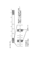
- FIG. 5 shows an example in which the frequency resource area indicated by the diagonal line pattern is designated as a D2D resource when the start RB index is set to “3” and the end RB index is set to “7”. Yes.
- the time direction resource allocation specifier is a radio frame start offset (start radio frame index) and D2D that can use the UL subframe in the radio frame for D2D, as shown in FIG.
- This is a specifier indicating the allocation period of the radio frame for use.
- the resource allocation specifier in the time direction is set to “1” for the start radio frame index and “6” as the allocation period of the radio frame for D2D, the horizontal line of the radio frame indicated by the diagonal line pattern
- the resource allocation specifier in the time direction in the case of the FDD system is a specifier indicating a subframe number that can be used for D2D, a start offset of the radio frame, and an allocation period of the radio frame for D2D.
- the first terminal device 10 and the second terminal device 20 perform the processing shown in the flowchart of FIG. 7, respectively, so that the band f2 notified in S1a and S1b or the frequency resource region in the band f2 D2D communication can be performed (S1c).
- the first terminal device 10 and the second terminal device 20 determine whether the terminal corresponds to the band f2 specified by the D2D resource information (S2a). Based on the D2D resource information, D2D communication is started using the specified resource (S2b). On the other hand, if the band f2 is not supported, it is determined whether the base station apparatus 30 has instructed the frequency resource region for D2D in the band f1 supported by the base station apparatus 30 currently performing the cellular communication. If it is instructed (S2c), D2D communication is started in the designated resource in the band f1 currently being cellular communication (S2d).
- the start of D2D communication is canceled and the base station device 30 is notified of abnormal termination (S2e).
- the notification of abnormal termination in S2e may be omitted.
- the base station apparatus notifies the broadcast information including D2D resource information in a band that is not supported by the base station, and the terminal apparatus is designated by this resource information. If the device is compatible with a band, communication between terminals is executed using the radio resource. Thereby, for example, an unused band in the cell can be effectively used, and the use of radio resources for cellular communication can be saved.
- Example 2 A second embodiment of the present invention will be described with reference to FIGS. 8, 9, 10A, and 10B.
- the second embodiment is a modification of the first embodiment.
- the difference from the first embodiment is that the resource information for D2D that has been notified by broadcasting in SIB or the like is notified through an individual channel such as RRC signaling. .
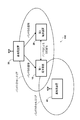
- FIG. 8 is a diagram of a configuration example of the wireless communication system according to the second embodiment.
- the first terminal apparatus 10 and the second terminal apparatus 20 exist in the cell area of the band f1 supported by the base station apparatus 30.
- D2D communication by the band f2 can be performed.
- the first terminal apparatus 10 during D2D communication using the band f2 moves, approaches the cell area of the base station apparatus 40 that supports the band f2 for cellular communication, and interference occurs in D2D communication. Assume a case.
- different D2D resource information for each terminal device since the notification is broadcast by SIB, different D2D resource information for each terminal device cannot be notified.
- different D2D resource information for each terminal device is RRC signaling. Can be notified individually.
- the D2D communication is performed depending on the position of each terminal apparatus or the measurement result of each terminal apparatus.
- the band that implements can be changed dynamically. As a result, it is possible to prevent the terminal device from erroneously using an unintended band.
- FIG. 9 is a sequence diagram illustrating an operation example of the wireless communication system according to the second embodiment.
- the first terminal apparatus 10 transmits a request signal for starting D2D communication with the second terminal apparatus 20 to the base station apparatus 30 (S3a).
- the base station device 30 sets the resource information for D2D that designates the band f2 that is not supported by the base station or the frequency resource region in the band f2 as a radio resource that can be used for D2D communication. Notification is made by RRC signaling (S3b).
- the base station device 30 transmits a measurement instruction of the D2D band f2 to the first terminal device 10 and the second terminal device 20 (S3c, S3d).
- the first terminal device 10 and the second terminal device 20 perform the D2D communication in the band f2 notified in S3b or the frequency resource region in the band f2 by performing the processing shown in the flowchart of FIG. (S3e).
- the first terminal apparatus 10 and the second terminal apparatus 20 measure the downlink radio quality for each cell in the base station apparatus 30 and the surrounding base station apparatuses. Then, when the first terminal apparatus 10 receives a cell reference signal from the base station apparatus 40 having a certain reception power or higher in the D2D band f2 (S3f), the first terminal apparatus 10 receives a measurement report to the base station apparatus 30.
- a signal related to measurement (measurement report) is transmitted (S3g). This measurement report can include the RSRP value and RSRQ value measured in S3f.
- the base station apparatus 30 performs a band reconfiguration determination process (B3h) for determining whether to change the band, using the S3g measurement report as a trigger (S3h). And based on this Band configuration decision, D2D resource pool configuration for notifying the change of the resource information for D2D is transmitted for each terminal device on an individual channel (S3i, S3j). For example, when there is an unused band f3, the base station apparatus 30 notifies the first terminal apparatus 10 and the second terminal apparatus 20 that are in D2D communication of D2D resource information including band information of the band f3. , The band f2 can be transited to the band f3. Note that if the base station apparatus 30 determines that the band should not be changed in the band reconfiguration determination process in S3h, the base station apparatus 30 does not transmit the change notification of the D2D resource information in S3i and S3j.
- B3h band reconfiguration determination process for determining whether to change the band, using the S3g measurement report as a trigger
- the band reconfiguration decision of S3h will be described.
- the band in which the terminal performs D2D communication can be changed for each terminal device.
- the base station device 30 uses information such as the RSRP value and the RSRQ value in the different band cell (f2) included in the measurement report from the terminal device as a trigger condition for this change, and uses the following Alt. It is determined whether or not a band should be transitioned according to any combination condition of 1 to 4, and a transition process is executed.
- band transition is executed. If the RSRP value or RSRQ value in the different band cell (f2) implementing D2D is equal to or greater than a predetermined threshold value, band transition is executed. If the RSRP value or the RSRQ value in the different band cell increases, there is a possibility of interference with the ongoing D2D communication. Therefore, the influence of interference is avoided by performing band transition to a frequency that does not interfere with the band f2.
- the amount of interference with respect to the different band cell (f2) performing D2D is estimated, and if the amount of interference is equal to or greater than a certain threshold, band transition is executed.
- the amount of interference can be estimated based on the transmission power of the base station and the cell size (for example, macro cell / micro cell).
- the terminal device If the RSRP value or the RSRQ value in the different band cell (f2) implementing D2D is a value equal to or greater than a predetermined threshold value, the terminal device is notified of the TDD config information. In the case of Alt.4, execution of band transition or resource allocation for D2D is entrusted to the terminal device.
- FIGS. 10A and 10B show the band transition processing procedure of Alt.4.
- FIG. 10A shows a case where a cell (for example, a 3.5 GHz cell) of a base station device 40 adjacent to the base station device 30 is not connected to a neighbor.
- FIG. 10B shows a case where the cell of the base station device 40 adjacent to the base station device 30 is connected to the neighbor. Note that S3e to S3g in FIGS. 10A and 10B indicate the same processing as S3e to S3g in FIG.
- the base station apparatus 30 when the base station apparatus 30 receives the measurement report in S3g as described in FIG. 9 above, the RSRP value or the RSRQ value in the different band cell (f2) included in the measurement report is greater than or equal to a predetermined threshold value.
- the first terminal apparatus 10 and the second terminal apparatus 20 are instructed to follow TDD config in a different band cell (S4b, S4c).
- the terminal device autonomously avoids the DL subframe of the band f2. Note that if the base station apparatus 30 determines in S4a that the RSRP value or RSRQ value in the different band cell (f2) is not equal to or greater than a predetermined threshold value, the base station apparatus 30 does not instruct S4b and S4c.
- the base station apparatus 30 when the base station apparatus 30 receives the measurement report in S3g, the RSRP value or the RSRQ value in the different band cell (f2) included in the measurement report is equal to or greater than a predetermined threshold.
- resource pool information corresponding to the TDD config of the neighboring cell is notified to the first terminal device 10 and the second terminal device 20 (S5b, S5c).
- the base station apparatus 30 does not perform notification of S5b and S5c, when it determines with the RSRP value or RSRQ value in a different band cell (f2) not being more than a predetermined threshold value in S5a.
- the second embodiment it is possible to dynamically change wireless resources from the wireless network side, and it is possible to appropriately manage a band for performing D2D communication. As a result, D2D communication can be provided while maintaining high communication continuity, and wireless resources can be effectively used.
- Example 3 A third embodiment of the present invention will be described with reference to FIGS.
- the third embodiment is a modification of the first and second embodiments.
- a band for performing D2D communication is distributed in consideration of QoS (Quality of Service). This makes it possible to provide appropriate radio quality according to the service request for each terminal device.
- QoS Quality of Service
- Example 3 for example, for each QCI (QoS Class indicator) described in Reference Document 3 (TS23.203 Ver.13.0.1, June 2014), a band for performing D2D communication, or a resource pool.
- Link areas For example, as shown in FIG. 11, QCI1 to QCI4 are linked to the D2D execution band f2, and QCI5 to 9 are linked to the D2D execution band f1.
- GBR Guard Bit Rate
- a D2D resource in a band in which cellular communication coexists is specified for a terminal device that performs service, and D2D resource allocation is performed with priority on cellular communication.
- the QCI table shown in FIG. 11 is not limited to this, and can be arbitrarily set. The QCI table may be changed as appropriate, for example, by determining the degree of congestion of each band in the base station.
- FIG. 12 is a sequence diagram illustrating an operation example of the wireless communication system according to the third embodiment when the first embodiment is used as a base.
- the base station apparatus 30 uses D2D resources including band information that can be used for D2D, or a frequency resource area in the band, and a D2D service type or an ID (for example, QCI) that identifies a service type permitted in each band.
- Information is notified to the 1st terminal device 10 and the 2nd terminal device 20 by SIB (S6a, S6b).
- SIB SIB
- the QCI1 to 4 are linked to the D2D execution band f2.
- the first terminal device 10 and the second terminal device 20 collate the QCI notified by the D2D resource information with the service type of the D2D traffic performed by the terminal itself, and perform D2D communication in the corresponding band (S6c). .
- FIG. 13 is a sequence diagram illustrating an operation example of the wireless communication system according to the third embodiment when the second embodiment is used as a base.
- the first terminal apparatus 10 transmits a request signal for starting D2D communication with the second terminal apparatus 20 to the base station apparatus 30 (S7a).
- this D2D communication request signal is notified to the base station apparatus 30 including information on the type of service performed by the terminal itself, in order to determine an appropriate band in the base station apparatus 30.
- the information regarding the type of service can include, for example, a service type or an ID (QCI or the like) for identifying the service type.
- the base station apparatus 30 instructs an appropriate band for the user to perform D2D communication related to the service type by RRC signaling individually (S7b).
- the base station device 30 transmits a measurement instruction for the D2D band to the first terminal device 10 and the second terminal device 20 (S7c, S7d).
- the first terminal apparatus 10 and the second terminal apparatus 20 perform the D2D communication in the band notified in S7b or the frequency resource region in the band by performing the processing shown in the flowchart of FIG. 7 (S7e). .
- the third embodiment it is possible to allocate an optimal radio resource for performing D2D communication according to a service type required in D2D communication, and to perform a band for performing D2D communication. Can be appropriately managed, and wireless resources can be used more effectively.
- the present invention has been described based on the embodiments.
- the present invention is not limited to the above-described embodiments and the contents of each embodiment, and various modifications can be made within the scope of the gist of the present invention.
- the above-mentioned embodiment is an exemplification, and various modifications can be made to the combination of each component and each processing process by combining each embodiment, and such a modification is also within the scope of the present invention. Will be understood by those skilled in the art.
Landscapes
- Engineering & Computer Science (AREA)
- Computer Networks & Wireless Communication (AREA)
- Signal Processing (AREA)
- Mobile Radio Communication Systems (AREA)
Abstract
基地局装置(E-UTRAN)は、その基地局装置においてサポートしていない周波数帯域を端末間通信に利用可能な無線リソースとして割り当て、割り当てた無線リソースを指定するリソース情報を第1端末装置および第2端末装置に対して送信する。
Description
本発明は、無線制御装置、端末装置および通信方法に関するものであり、具体的には、無線通信システムにおいて、端末装置間で直接通信を行うための無線制御装置、端末装置、および通信方法に関するものである。
近年、E-UTRAN(Evolved Universal Terrestrial Radio Access Network)においては、複数の端末装置(User Equipment。以下、UEという。)が基地局を介さずに直接通信を行うための技術である端末間通信(Device to Device Communication。以下、D2D通信という。)について議論がなされている。
D2D通信は、例えば、LTEなどのセルラ通信のアップリンクに使用されている無線リソースの一部を用いて実行される。D2D通信が適用可能となる端末装置間の距離は、数100m程度と言われている。3GPP(3rd Generation Partnership Project) Release 12では、端末装置が近傍に位置する端末を検出する方法や、不特定の端末装置に対してデータをブロードキャストする手法が提案されている(たとえば、非特許文献1または2を参照。)。
3GPP TR23.703 Ver.0.4.1 "study on architecture enhancements to support proximity services (ProSe)" 2013年1月
3GPP TR36.843 Ver.12.0.1 "Study on LTE Device to Device Proximity Services" 2014年3月
しかしながら、端末間通信に用いられていた周波数バンドが利用不可能もしくは利用に適さないような状態となった場合に端末間通信を継続することができないという課題があった。
本発明はかかる課題に鑑みてなされたものであり、その目的は、端末間通信の高い継続性を実現する無線制御装置、端末装置、および通信方法を提供することにある。
本発明の一態様に係る無線制御装置は、複数の端末装置の間で、基地局装置を介さずに直接的に無線通信を行う端末間通信を制御する無線制御装置であって、基地局装置においてサポートしていない周波数帯域を端末間通信に利用可能な無線リソースとして割り当てる制御部と、制御部によって割り当てた無線リソースに関するリソース情報を端末装置に対して送信する無線通信部とを備える。また、無線通信部は、リソース情報を報知チャネルで送信してもよい。また、無線通信部は、リソース情報として、周波数リソースに関する情報および/または時間リソースに関する情報を送信してもよい。また、無線通信部は、制御部によって割り当てた無線リソースを用いた端末間通信において許可される1以上のサービスタイプに関する情報をさらに送信してもよい。
このような態様によると、無線ネットワーク側から動的な無線リソースの変更が可能となり、端末間通信を実施するバンドを適切に管理することが可能になる。これにより、端末間通信を高い通信継続性を保持した上で提供でき、無線リソースの有効活用が可能になる。なお、無線制御装置とは、たとえば、E-UTRANを含み、基地局装置、あるいは、その上位装置を含めた概念である。
また、制御部は、端末装置ごとに無線リソースを割り当て、無線通信部は、端末装置ごとに割り当てた無線リソースを指定するリソース情報を個別チャネルで送信してもよい。また、無線通信部は、制御部において端末装置ごとに無線リソースを割り当てた後に、端末装置から報告された無線品質に関する測定情報を受信し、制御部は、端末装置からの測定情報を基に、割り当てた無線リソースを切り替えるか否かを判定し、切り替えるべきと判定された場合には切り替えに関する切替情報を生成し、無線通信部は、制御部によって生成された切替情報を当該端末装置に送信してもよい。また、無線通信部は、制御部において端末装置に無線リソースを割り当てた後に、端末装置から報告された無線品質に関する測定情報を受信し、制御部は、端末装置からの測定情報を基に、割り当てた無線リソースを切り替えるか否かを判定し、切り替えるべきではないと判定された場合には切り替えに関する切替情報を当該端末装置に送信しないようにしてもよい。また、制御部は、端末間通信においてなされるサービスタイプであって端末装置からの要求されたサービスタイプに基づいて、そのサービスタイプに使用すべき無線リソースを割り当ててもよい。
このような態様によると、無線ネットワーク側から、より適切な無線リソースへの変更が可能となり、端末間通信を実施するバンドを適切に管理することが可能になる。これにより、端末間通信を高い通信継続性を保持した上で提供でき、無線リソースの有効活用が可能になる。
本発明の別の一態様に係る端末装置は、複数の端末装置の間で基地局装置を介さずに直接的に無線通信を行う端末間通信を行う端末装置であって、基地局装置においてサポートしていない周波数帯域を端末間通信に利用可能な無線リソースとして指定するリソース情報を受信する通信部と、当該端末装置がリソース情報で指定される無線リソースに対応しているかを判断し、対応している場合は無線リソースを利用して端末間通信を実行し、対応していない場合は、基地局装置においてサポートしており、かつ、端末間通信のために使用が許可されている利用可能な無線リソースを利用して端末間通信を実行する制御部とを備える。
このような態様によると、端末装置は、リソース情報で指定される無線リソースに対応している場合には、当該無線リソースを利用して端末間通信を継続して実行できる。また、未使用バンドを有効利用でき、セルラ通信の無線リソースの利用を節約できる。
本発明のさらに別の一態様に係る通信方法は、複数の端末装置と、複数の端末装置の間で基地局装置を介さずに直接的に無線通信を行う端末間通信を制御する無線制御装置とを備える通信システムにおける通信方法であって、無線制御装置は、基地局装置においてサポートしていない周波数帯域を端末間通信に利用可能な無線リソースとして割り当て、割り当てた無線リソースを指定するリソース情報を端末装置に対して送信し、端末装置は、リソース情報を受信し、当該端末装置がリソース情報で指定される無線リソースに対応しているかを判断し、対応している場合は、無線リソースを利用して端末間通信を実行し、対応していない場合は、基地局装置がサポートしている周波数帯域内における端末間通信に利用可能な無線リソースを利用して端末間通信を実行する。
なお、以上の構成要素の任意の組み合わせ、本発明の表現を方法、装置、システム、コンピュータプログラムなどの間で変換したものもまた、本発明の態様として有効である。
本発明によれば、端末間通信の高い継続性を実現し、無線リソースの有効活用を可能にする無線制御装置、端末装置、および通信方法を提供できる。
本発明のその他の特徴及び利点は、添付図面を参照とした以下の説明により明らかになるであろう。なお、添付図面においては、同じ若しくは同様の構成には、同じ参照番号を付す。
添付図面は明細書に含まれ、その一部を構成し、本発明の実施の形態を示し、その記述と共に本発明の原理を説明するために用いられる。
本発明の一実施形態にかかる無線通信システムの構成例を示す図である。
図1の端末装置の構成例を示す図である。
図1の基地局装置の構成例を示す図である。
実施例1にかかる無線通信システムの動作例を示すシーケンス図である。
D2D用周波数帯域指定子の一例を示す図である。
時間方向のリソース割当指定子の一例を示す図である。
実施例1にかかる端末装置の動作例を示すフローチャートである。
実施例2にかかる無線通信システムの構成例を示す図である。
実施例2にかかる無線通信システムの動作例を示すシーケンス図である。
実施例2にかかるバンド遷移処理の一例を示すシーケンス図である。
実施例2にかかるバンド遷移処理の一例を示すシーケンス図である。
実施例3におけるD2D用リソースの割当例を示す図である。
実施例3にかかる無線通信システムの動作例を示すシーケンス図である。
実施例3にかかる無線通信システムの動作例を示すシーケンス図である。
(本発明の概要)
本発明の実施例を説明する前に、まず、本発明の概要を述べる。本発明は、端末装置同士が直接的に無線通信を行うD2D通信の技術に関する。本発明にかかる無線制御装置は、基地局装置においてサポートしていない周波数帯域をD2D通信に利用可能な無線リソースとして割り当て、割り当てた無線リソースを指定するリソース情報を端末装置に対して送信する。また、端末装置は、上記リソース情報を受信すると、当該端末装置がリソース情報で指定される無線リソースに対応しているかを判断し、対応している場合は、この無線リソースを利用して端末間通信を実行し、対応していない場合は、基地局装置がサポートしている周波数帯域内における端末間通信に利用可能な無線リソースを利用して端末間通信を実行するものである。
本発明の実施例を説明する前に、まず、本発明の概要を述べる。本発明は、端末装置同士が直接的に無線通信を行うD2D通信の技術に関する。本発明にかかる無線制御装置は、基地局装置においてサポートしていない周波数帯域をD2D通信に利用可能な無線リソースとして割り当て、割り当てた無線リソースを指定するリソース情報を端末装置に対して送信する。また、端末装置は、上記リソース情報を受信すると、当該端末装置がリソース情報で指定される無線リソースに対応しているかを判断し、対応している場合は、この無線リソースを利用して端末間通信を実行し、対応していない場合は、基地局装置がサポートしている周波数帯域内における端末間通信に利用可能な無線リソースを利用して端末間通信を実行するものである。
通常、セルラシステムにおいて端末装置が通信を実施するためには、基地局が端末装置の存在するエリアに展開されている必要がある。しかしながら、基地局の設置は、様々な手続きが必要であり、非常にコストのかかる作業である。一方で、例えば、上述したD2D通信技術は、基地局を介さずに当該端末装置間で直接通信をする技術である。このD2D通信の実施のためには、必ずしも基地局の存在を必要としないため、前述のような基地局の設置コスト無しに実現可能である。
このように基地局の設置作業のコストは非常に高いため、小セルのような1基地局あたりでカバーする面積の狭い基地局を、全国に展開することは非常に困難である。このため、例えば小セル専用に利用可能なバンド(周波数帯域)がある場合でも、当該バンドを小セルが未展開となるエリアにおいては、そのバンドを通信に利用できないこととなる。前述のD2D通信技術を用いれば当該バンドを利用した通信が可能であるが、端末装置が当該バンドをD2D通信に利用可能であることを知る術がない。また、当該バンドを独立したアドホックバンドとして利用することが従来技術により可能であるが、この場合にも当該バンドが利用不可能となった場合に通信を継続することができない、という課題があった。
本発明は、以上の課題を解決しており、無線ネットワーク側から動的な無線リソースの変更が可能となり、端末間通信を実施するバンドを適切に管理することが可能になる。これにより、端末間通信を高い通信継続性を保持した上で提供でき、さらには、無線リソースの有効活用が可能になる。
(無線通信システムの構成例)
図1は、本発明の一実施形態にかかる無線通信システムの構成例を示す図である。例えば、無線通信システム100は、第1端末装置10と、第2端末装置20と、LTE方式の無線アクセスネットワークを構成する基地局装置(E-UTRAN)30とを含む。
図1は、本発明の一実施形態にかかる無線通信システムの構成例を示す図である。例えば、無線通信システム100は、第1端末装置10と、第2端末装置20と、LTE方式の無線アクセスネットワークを構成する基地局装置(E-UTRAN)30とを含む。
基地局装置30は、セルラ通信用にバンドf1をサポートしている。第1端末装置10および第2端末装置20は、バンドf1のセルエリアに位置しており、バンドf1を利用して基地局装置30との間でセルラ通信を実施可能である。また、第1端末装置10および第2端末装置20は、バンドf1内の無線リソースを利用して、基地局装置30を経由しない端末間通信(D2D通信)が実行可能な端末である。ここでは、第1端末装置10および第2端末装置20は、基地局装置30に対してRRC_CONNECTED状態であるものとする。RRC_CONNECTED状態とは、基地局装置によって無線リソースが管理され、端末装置がデータを送受信できる状態を指し、データの送受信、CQI(Channel Quality Indicator)などの情報の基地局装置へのフィードバックなどの機能が実行可能な状態となっている。
さらに、本実施形態においては、基地局装置30は、当該基地局がサポートしていないバンドf2における無線リソースをD2D通信に利用することを許可する通知(リソース情報)を、第1端末装置10および第2端末装置20に送信することができる。この通知を受信することにより、第1端末装置10および第2端末装置20は、バンドf2における無線リソースを利用して、相手方の端末装置との間でD2D通信を実施することが可能になる。これにより未使用バンドを有効利用でき、セルラ通信の無線リソースの利用を節約できる。なお、サポートしている/サポートしていないとは、当該バンドについての通信機能を備えていないことを含み、また、通信機能を備えているが当該バンドの使用が許可されていないことなども含む。なお、本発明は上記構成に限定されるものではなく、第1端末装置10および第2端末装置20のいずれかが基地局装置30に対してRRC_CONNECTED状態であればよい。例えば、第1端末装置10のみが基地局装置30からバンドf2における無線リソースをD2D通信に利用することを許可する通知を受信し、基地局装置30の替わりに第1端末装置10が第2端末装置20に対して、当該バンドf2が利用可能であることを通知することも可能である。以降で説明する各実施例についても同様である。
(端末装置の構成例)
図2は、図1の第1端末装置10および第2端末装置20として用いられる端末装置の構成例を示す図である。端末装置は、通信部12と、制御部14と、記憶部16と、ユーザインタフェース(ユーザIF)18とを備える。
図2は、図1の第1端末装置10および第2端末装置20として用いられる端末装置の構成例を示す図である。端末装置は、通信部12と、制御部14と、記憶部16と、ユーザインタフェース(ユーザIF)18とを備える。
通信部12は、セルラ通信部122と、端末間通信部124とを含む。セルラ通信部122は、基地局装置30との間で無線により通信を行う。端末間通信部124は、基地局装置によって割り当てられたD2D通信のための無線リソースを利用して、D2D通信の相手方となる端末装置との間で、基地局装置30を経由せずに直接的に通信を行う。これらの通信処理は、公知の変復調技術、アンテナ技術が用いられてもよい。
記憶部16は、基地局装置30もしくはD2D通信の相手方の端末装置から送信されたデータを記憶し、また、基地局装置30もしくはD2D通信の相手方の端末装置に対して送信すべき、ユーザIF18を通じて得たデータを記憶してもよい。ユーザIF18は、画面インタフェースと、操作ボタンやタッチパネルなどのユーザからの入力を受け付ける入力インタフェースと、カメラなどの画像撮像手段を含んでもよい。
制御部14は、例えば、CPUにより構成され、セルラ通信部122もしくは端末間通信部124から受信された情報、または記憶部16に記憶された情報を用いて、各部を統括的に制御する。
制御部14は、基地局装置30においてサポートしていないバンドf2を端末間通信に利用可能な無線リソースとして指定するリソース情報をセルラ通信部122により受信すると、当該端末装置がこのリソース情報で指定されるバンドf2の無線リソースに対応しているかを判断する。制御部14は、バンドf2に対応している場合は、バンドf2の無線リソースを利用して、端末間通信部124により相手方の端末装置との間におけるD2D通信の実行を制御する。対応していない場合は、基地局装置30からの制御メッセージ等により、基地局装置30がサポートしているバンドf1内におけるD2D通信に利用可能な無線リソースが予め通知されている場合は、バンドf1の無線リソースを利用して、D2D通信を実行することができる。
また、制御部14は、セルラ通信部122により受信した無線信号を用いて、基地局装置30および周辺の基地局装置におけるセル毎のダウンリンクの無線品質を測定する。また、制御部14は、端末間通信においてお互いに既知信号を送信しあうことにより、端末間通信に用いられている無線リソースについての無線品質を測定してもよい。例えば、LTEシステムにおいては、無線品質として、参照信号の受信信号電力(RSRP:Reference Signal Received Power)および/または受信信号品質(RSRQ:Reference Signal Received Quality)が測定される。制御部14は、必要に応じて、セル毎の識別子(ID)などの測定対象と、測定した無線品質とを含む無線品質情報を基地局装置30に報告する。
(基地局装置30の構成例)
図3は、図1の基地局装置30の構成例を示す図である。基地局装置30は、通信部32と、制御部34と、記憶部36とを含む。
図3は、図1の基地局装置30の構成例を示す図である。基地局装置30は、通信部32と、制御部34と、記憶部36とを含む。
通信部32は、無線通信部322と、ネットワーク通信部324とを含む。無線通信部322は、記憶部36に記憶された情報を制御部34が使用しながら、自局のセルエリアに属する第1端末装置10、第2端末装置20のそれぞれと、所定のセルラ方式を用いてセルラ無線通信を実行する。ネットワーク通信部324は、X2インタフェース等を介して、隣接する他の基地局装置との間で基地局間通信を行う。記憶部36には、ネットワーク通信部324を介して隣接する他の基地局装置から取得されるTDD config情報などが記憶される。
無線通信部322は、制御部34によって割り当てた無線リソースに関するリソース情報を端末装置に対して送信する。このリソース情報は、報知チャネルを用いて報知により送信されてもよいし、個別チャネルにて特定の端末装置に向けて送信されてもよい。また、リソース情報は、周波数リソースに関する情報および/または時間リソースに関する情報を含んでもよい。また、無線通信部322は、制御部34において端末装置ごとに無線リソースを割り当てた後に、端末装置から報告された無線品質に関する測定情報を受信し、この測定情報をもとに制御部34によって生成された切替情報を当該端末装置に送信してもよい。また、無線通信部322は、制御部34によって割り当てた無線リソースを用いた端末間通信において許可される1以上のサービスタイプに関する情報をさらに送信してもよい。なお、サービスタイプの詳細については後述する。
制御部34は、基地局装置30がサポートしているバンドf1内におけるD2D通信に利用可能な無線リソースを制御メッセージ等により、第1端末装置10および第2端末装置20に通知する。さらに、制御部34は、基地局装置30においてサポートしていないバンドf2をD2D通信に利用可能な無線リソースとして割り当て、割り当てた無線リソースを指定するリソース情報を第1端末装置10および第2端末装置20に対して送信することができる。このリソース情報は、バンドf1のセルエリアに位置する端末装置に対して、報知チャネルでブロードキャスト通知することができる。また、制御部34は、端末装置ごとにバンドf2における無線リソースを割り当て、端末装置ごとに割り当てた無線リソースを指定するリソース情報を個別チャネルで送信してもよい。
また、制御部34は、端末装置から報告された測定情報を基に、割り当てた無線リソースを切り替えるか否かを判定し、切り替えるべきと判定された場合には切り替えに関する切替情報を生成してもよい。切替情報には、切り替え先の無線リソースに関する情報が含まれていてもよい。また、制御部34は、端末間通信においてなされるサービスタイプであって端末装置からの要求されたサービスタイプに基づいて、そのサービスタイプに使用すべき無線リソースを割り当ててもよい。なお、「切替」という用語は、「変更」「修正」「遷移」「移行」「取替」「代替」「取替」「設定」「再設定」などの用語に置き換えられてもよい。
また、LTEにおいては、QoS(Quality of Service)制御におけるクラスを定めるQCI(QoS Class Identifier)が定義されている。基地局装置30は、QCIに関する情報(QCIテーブル)を記憶部36に予め記憶している。制御部34は、D2D通信に要求されるサービス品質(QoS)のクラス(QCI)に基づいて、バンドf2あるいはバンドf1における無線リソースを割り当てることができる。
リソース情報は、例えば、D2D通信に利用可能なバンド情報、当該バンド内の周波数リソース領域、EARFCN(E-UTRAN absolute radio frequency channel number)、D2D用の無線リソースの帯域幅、システムフレームナンバー、再送制御フォーマット指定チャネル(PHICH)の設定情報、あるいは下り帯域幅、または上記情報の任意の組み合わせを含むことができる。
次に、このように構成された無線通信システムの動作について、各実施例に従って説明する。なお、各実施例において、既出の構成、動作については、同じ符号を用いることによってその説明を簡略化する。以下、本明細書において同様である。
(実施例1)
本発明の実施例1について、図4乃至図7を用いて説明する。実施例1においては、上記図1に示したように、基地局装置30のサポートするバンドf1のセルエリアに第1端末装置10および第2端末装置20が存在する。実施例1では、当該バンドf1のセルエリアにおいて、D2D通信に利用可能な無線リソースとして、当該基地局のサポートしていないバンドf2のバンド情報、または当該バンドf2内の周波数リソース領域、またはその両方を含むリソース情報を、当該セルの基地局装置30から報知チャネルに含めて第1端末装置10および第2端末装置20に通知する。
本発明の実施例1について、図4乃至図7を用いて説明する。実施例1においては、上記図1に示したように、基地局装置30のサポートするバンドf1のセルエリアに第1端末装置10および第2端末装置20が存在する。実施例1では、当該バンドf1のセルエリアにおいて、D2D通信に利用可能な無線リソースとして、当該基地局のサポートしていないバンドf2のバンド情報、または当該バンドf2内の周波数リソース領域、またはその両方を含むリソース情報を、当該セルの基地局装置30から報知チャネルに含めて第1端末装置10および第2端末装置20に通知する。
図4は、実施例1にかかる無線通信システムの動作例を示すシーケンス図である。図4において、基地局装置30は、当該基地局がサポートしていないバンドf2をD2D通信に利用可能な無線リソースとして指定するリソース情報(D2D用リソース情報)をSIB(System Information Block)に含めて、第1端末装置10および第2端末装置20にブロードキャスト通知する(S1a,S1b)。
ここで、D2D用リソース情報とは、D2D通信に利用可能なバンド情報、または当該バンド内の周波数リソース領域、またはD2D用の無線リソースの帯域幅、またはシステムフレームナンバー、または再送制御フォーマット指定チャネル(PHICH)の設定情報、または下り帯域幅、または上記情報の任意の組み合わせである。
バンド情報は、例えばバンド指定子により通知することができる。バンド指定子とは、予め異なる周波数帯域に対応している指定子、f1,f2,f3,…,fnである。そのような指定子として、例えば、参考文献1(TS36.101 Ver.12.0.0, 2013年7月)に記載されるband indicatorや、参考文献2(TS36.104)に記載されるEARFCN(E-UTRAN absolute radio frequency channel number)により指定されるキャリア周波数番号が利用可能である。
当該バンド内の周波数リソース領域は、例えば、周波数方向のD2D用周波数帯域指定子と時間方向のリソース割当指定子とを指定することで通知、周波数方向のD2D用周波数帯域指定子のみを通知、または、時間方向のリソース割当指定子のみを通知することができる。
D2D用周波数帯域指定子とは、図5に示すように、当該バンド内のリソースブロック(RB)に対して周波数方向にインデックス(RB index)を付与し、D2D用に割り当てることを意図するリソースブロックを示すインデックスrange(開始RB index、終了RB index)を通知する指定子である。図5では、周波数帯域指定子を、開始RB indexを“3”、終了RB indexを“7”とする場合に、斜線パターンで示される周波数リソース領域がD2D用リソースとして指定される例を表している。
時間方向のリソース割当指定子とは、TDDシステムの場合は、図6に示すように、当該radio frame内のUL subframeをD2D用に利用可能なradio frameの開始オフセット(開始radio frame index)とD2D用radio frameの割当周期とを示す指定子とする。図6では、時間方向のリソース割当指定子を、開始radio frame indexを“1”、D2D用radio frameの割当周期を“6”とする場合に、斜線パターンで示されるradio frameのうちの、横線パターンで示すUL subframeがD2D用リソースとして指定される例を表している。また、FDDシステムの場合の時間方向のリソース割当指定子は、D2D用に利用可能なsubframe番号と、radio frameの開始オフセットと、D2D用radio frameの割当周期を示す指定子とする。
図4に戻って、第1端末装置10および第2端末装置20は、図7のフローチャートに示す処理をそれぞれ行うことで、S1a,S1bにおいて通知されたバンドf2または当該バンドf2内の周波数リソース領域におけるD2D通信を実施することができる(S1c)。
図7において、先ず、第1端末装置10および第2端末装置20は、D2D用リソース情報により指定されたバンドf2に当該端末が対応しているかを判断し(S2a)、対応している場合は、当該D2D用リソース情報に基づき、指定されたリソースを利用してD2D通信を開始する(S2b)。一方、バンドf2に対応していない場合は、現在セルラ通信を実施中の基地局装置30のサポートしているバンドf1内におけるD2D用の周波数リソース領域が基地局装置30から指示されているかを判断し(S2c)、指示されている場合は、現在セルラ通信中のバンドf1における指定されたリソースにおいてD2D通信を開始する(S2d)。バンドf1内におけるD2D用の周波数リソース領域が基地局装置30から指示されていない場合は、D2D通信の開始をキャンセルし、異常終了した旨を基地局装置30に通知する(S2e)。S2eの異常終了の通知は省略してもよい。
以上述べたように、実施例1によれば、基地局装置において、報知情報に当該基地局がサポートしないバンドにおけるD2D用リソース情報を含めて通知し、端末装置は、このリソース情報で指定されるバンドに対応している場合には、当該無線リソースを利用して端末間通信を実行する。これにより、例えば、当該セル内で未使用のバンドを有効利用でき、セルラ通信の無線リソースの利用を節約することが可能になる。
(実施例2)
本発明の実施例2について、図8、図9、図10A、および図10Bを用いて説明する。実施例2は、実施例1の変形例であり、実施例1との相違点は、SIB等でブロードキャストにより通知していたD2D用リソース情報を、RRC signaling等の個別チャネルで通知する点にある。
本発明の実施例2について、図8、図9、図10A、および図10Bを用いて説明する。実施例2は、実施例1の変形例であり、実施例1との相違点は、SIB等でブロードキャストにより通知していたD2D用リソース情報を、RRC signaling等の個別チャネルで通知する点にある。
図8は、実施例2にかかる無線通信システムの構成例を示す図である。無線通信システム110には、図1と同様に、基地局装置30のサポートするバンドf1のセルエリアに第1端末装置10および第2端末装置20が存在している。そして、第1端末装置10と第2端末装置20との間では、基地局装置30から通知されるリソース情報に基づいて、バンドf2によるD2D通信を実行することができる。さらに、実施例2では、バンドf2によるD2D通信中の第1端末装置10が移動して、当該バンドf2をセルラ通信用にサポートする基地局装置40のセルエリアに近づき、D2D通信に干渉が生じる場合を想定する。
実施例1ではSIBでブロードキャストによる通知であるために、端末装置ごとに異なるD2D用リソース情報を通知することができなかったが、実施例2では、端末装置ごとに異なるD2D用リソース情報をRRC signalingで個別に通知できるようになる。これによって、当該バンドf2をセルラ通信用にサポートする基地局装置40とサポートしない基地局装置30とが混在するエリアでは、各端末装置の位置または各端末装置によるmeasurementの結果に応じて、D2D通信を実施するバンドを動的に変更することができる。これによって、意図しないバンドを端末装置が誤って利用することを抑制することができる。
図9は、実施例2にかかる無線通信システムの動作例を示すシーケンス図である。図9において、第1端末装置10は、第2端末装置20との間でD2D通信を開始するための要求信号を基地局装置30へ送信する(S3a)。基地局装置30は、S3aの要求信号を受信すると、当該基地局がサポートしていないバンドf2または当該バンドf2内の周波数リソース領域をD2D通信に利用可能な無線リソースとして指定するD2D用リソース情報をRRC signallingで通知する(S3b)。さらに、基地局装置30は、D2D用バンドf2のmeasurement指示を第1端末装置10および第2端末装置20に送信する(S3c,S3d)。
第1端末装置10および第2端末装置20は、上記図7のフローチャートに示す処理をそれぞれ行うことで、S3bにおいて通知されたバンドf2または当該バンドf2内の周波数リソース領域におけるD2D通信を実施することができる(S3e)。D2D通信中において、第1端末装置10および第2端末装置20は、基地局装置30および周辺の基地局装置におけるセル毎のダウンリンクの無線品質を測定している。そして、図8に示すような状態となり、第1端末装置10は、D2Dバンドf2において一定受信電力以上の基地局装置40からのセルリファレンス信号を受信すると(S3f)、基地局装置30へ測定報告に関する信号(measurement report)を送信する(S3g)。このmeasurement reportには、S3fで測定したRSRP値やRSRQ値を含むことができる。
基地局装置30は、S3gのmeasurement reportをトリガにして、バンド遷移するかを決定するためのバンド再設定判定処理(Band reconfiguration decision)を行う(S3h)。そして、このBand reconfiguration decisionに基づいて、D2D用リソース情報の変更を通知するためのD2D resource pool reconfigurationを端末装置ごとに個別チャネルで送信する(S3i,S3j)。例えば、基地局装置30は、未使用のバンドf3が存在する場合には、バンドf3のバンド情報を含むD2D用リソース情報をD2D通信中の第1端末装置10および第2端末装置20に通知し、バンドf2からバンドf3へ遷移させることができる。なお、基地局装置30は、S3hのバンド再設定判定処理においてバンドを遷移すべきでないと判定した場合は、S3i、S3jのD2D用リソース情報の変更通知の送信は行わない。
ここで、S3hのBand reconfiguration decisionについて説明する。実施例2では、S3i,S3jのように、端末装置ごとに当該端末がD2D通信を実施するバンドを変更することができる。例えば、基地局装置30は、この変更のためのトリガ条件として、端末装置からのmeasurement reportに含まれる異バンドセル(f2)におけるRSRP値やRSRQ値等の情報を利用して、以下のAlt.1~4の任意の組み合わせ条件によってバンドを遷移すべきか否かを判定し、遷移処理を実行する。
[Alt.1]D2Dを実施している異バンドセル(f2)におけるRSRP値またはRSRQ値が、所定の閾値以上の値であれば、バンド遷移を実行する。異バンドセルにおけるRSRP値またはRSRQ値が大きくなると、実施中のD2D通信に干渉を与える可能性があるため、バンドf2と干渉しない周波数にバンド遷移させることで干渉の影響を避けるようにする。
[Alt.2]D2Dを実施している異バンドセル(f2)に対する与干渉量を見積もり、与干渉量が一定閾値以上であれば、バンド遷移を実行する。与干渉量は、基地局の送信電力やセルサイズ(例えば、マクロセル/ミクロセル)によって見積もることができる。
[Alt.3]D2Dを実施している異バンドセル(f2)におけるRSRP値またはRSRQ値が、所定の閾値以上の値であれば、バンドf2のUL subframeにおいてのみリソースを割り当てるようにする。基地局装置40のサポートするバンドf2のDL subframeの使用を避けることで、近隣に存在する端末の実施する下りセルラ通信に与える干渉を低減することが可能になる。
[Alt.4]D2Dを実施している異バンドセル(f2)におけるRSRP値またはRSRQ値が、所定の閾値以上の値であれば、端末装置に対して当該TDD config情報を通知する。このAlt.4の場合は、端末装置にD2D用のバンド遷移またはリソース割り当ての実行を委ねることになる。
図10Aおよび図10Bに、Alt.4のバンド遷移処理の手順を示す。図10Aは、基地局装置30が隣接する基地局装置40のセル(例えば3.5GHzセル)とネイバーがはられていない場合を示す。図10Bは、基地局装置30が隣接する基地局装置40のセルとネイバーがはられている場合を示す。なお、図10Aおよび図10BのS3e~S3gは、上記図9のS3e~S3gと同一の処理を示している。
図10Aにおいて、基地局装置30は、上記図9で説明したように、S3gでmeasurement reportを受信すると、measurement reportに含まれる異バンドセル(f2)におけるRSRP値またはRSRQ値が、所定の閾値以上の場合に(S4a)、異バンドセルにおけるTDD configに従うように第1端末装置10および第2端末装置20に指示する(S4b,S4c)。例えば、基地局装置30が隣接する基地局装置40のバンドf2セルとの間でネイバーがはられて(X2インタフェースやバックホールリンクなどを介して互いに通信可能な状態が確立されて)いなければ、当該バンドf2セルにおける基地局装置40のTDD Configも把握できないため、端末装置において自律的にバンドf2のDL subframeを避けてもらうようにする。なお、基地局装置30は、S4aにおいて異バンドセル(f2)におけるRSRP値またはRSRQ値が、所定の閾値以上でないと判定した場合は、S4b、S4cの指示は行わない。
図10Bにおいて、基地局装置30は、上記図9で説明したように、S3gでmeasurement reportを受信すると、measurement reportに含まれる異バンドセル(f2)におけるRSRP値またはRSRQ値が、所定の閾値以上の場合に(S5a)、隣接セルのTDD configに応じたresource pool情報を第1端末装置10および第2端末装置20に通知する(S5b,S5c)。例えば、基地局装置30が隣接する基地局装置40のバンドf2のセルとネイバーがはられていれば、当該セルにおける基地局装置40のTDD config情報をX2インタフェースで取得することができる。取得したTDD config情報に合わせたリソース情報をRRC signallingで通知する。なお、基地局装置30は、S5aにおいて異バンドセル(f2)におけるRSRP値またはRSRQ値が、所定の閾値以上でないと判定した場合は、S5b、S5cの通知は行わない。
以上述べたように、上記実施例2によれば、無線ネットワーク側から動的な無線リソースの変更が可能となり、D2D通信を実施するバンドを適切に管理することが可能になる。これにより、D2D通信を高い通信継続性を保持した上で提供でき、無線リソースの有効活用が可能になる。
(実施例3)
本発明の実施例3について、図11乃至図13を用いて説明する。実施例3は、実施例1および2の変形例であり、実施例1または2において、QoS(Quality of Service)を考慮して、D2D通信を実施するバンドを振り分けるようにする。これにより、端末装置ごとのサービス要求に応じた適切な無線品質を提供可能になる。
本発明の実施例3について、図11乃至図13を用いて説明する。実施例3は、実施例1および2の変形例であり、実施例1または2において、QoS(Quality of Service)を考慮して、D2D通信を実施するバンドを振り分けるようにする。これにより、端末装置ごとのサービス要求に応じた適切な無線品質を提供可能になる。
実施例3では、例えば、参考文献3(TS23.203 Ver.13.0.1, 2014年6月)に記載されるQCI(QoS Class indicator)ごとに、D2D通信を実施するバンド、またはresource pool領域を紐づける。例えば、図11に示すように、D2D実施用バンドf2にQCI1~4を紐付け、D2D実施用バンドf1にQCI5~9を紐付けておく。すなわち、GBR(Guaranteed Bit Rate)トラフィックに分類されるサービスを実施する端末装置に対してはセルラ通信の存在しないバンドを指定することでリソース割当の自由度を高め、non-GBRトラフィックに分類されるサービスを実施する端末装置に対してはセルラ通信が共存するバンドにおけるD2D用リソースを指定し、セルラ通信を優先したD2Dリソース割当を行う。なお、図11に示したQCIテーブルは、これに限らず任意の設定が可能であるとする。QCIテーブルは、例えば基地局における各バンドの混雑度の判断などによって適宜変更されてもよい。
図12は、実施例1をベースとする場合の実施例3にかかる無線通信システムの動作例を示すシーケンス図である。基地局装置30は、D2D用に利用可能なバンド情報、または当該バンド内の周波数リソース領域と、各バンドにおいて許可するD2Dサービスタイプまたはサービスタイプを識別するID(例えばQCI)とを含むD2D用リソース情報を、SIBで第1端末装置10および第2端末装置20へ通知する(S6a,S6b)。例えば、D2D実施用バンドf2にQCI1~4を紐付けて通知する。第1端末装置10および第2端末装置20は、D2D用リソース情報により通知されたQCIと自端末が行うD2Dトラフィックのサービスの種別とを照合し、対応するバンドにおけるD2D通信を実施する(S6c)。
図13は、実施例2をベースとする場合の実施例3にかかる無線通信システムの動作例を示すシーケンス図である。第1端末装置10は、第2端末装置20との間でD2D通信を開始するための要求信号を基地局装置30へ送信する(S7a)。実施例3では、このD2D通信要求信号に、基地局装置30における適切なバンドの判断のために、自端末が行うサービスの種別に関する情報を含めて基地局装置30に対して通知する。サービスの種別に関する情報とは、例えば、サービスタイプ、またはサービスタイプを識別するID(QCIなど)などを含むことができる。基地局装置30は、要求信号により通知されたサービスタイプに基づいて、当該端末がそのサービスタイプにかかるD2D通信を実施するのに適切なバンドをユーザ個別にRRC signallingで指示する(S7b)。
その後は、実施例2と同様に、基地局装置30は、D2D用バンドのmeasurement指示を第1端末装置10および第2端末装置20に送信する(S7c,S7d)。第1端末装置10および第2端末装置20は、上記図7のフローチャートに示す処理をそれぞれ行うことで、S7bにおいて通知されたバンドまたは当該バンド内の周波数リソース領域におけるD2D通信を実施する(S7e)。
以上述べたように、上記実施例3によれば、D2D通信において要求されるサービスタイプに応じて、D2D通信を実施すべき最適な無線リソースを割り当てることができ、また、D2D通信を実施するバンドを適切に管理することができ、無線リソースをさらに有効活用することが可能になる。
以上、本発明を実施例をもとに説明した。本発明は上述した実施例並びに各実施例の内容に限定されるものではなく、本発明の要旨の範囲内において種々に変形して実施をすることが可能である。上記実施例は例示であり、各実施例を組み合わせるなどして、それらの各構成要素や各処理プロセスの組み合わせにいろいろな変形例が可能なこと、またそうした変形例も本発明の範囲にあることは当業者に理解されるところである。
本発明は上記実施の形態に制限されるものではなく、本発明の精神及び範囲から離脱することなく、様々な変更及び変形が可能である。従って、本発明の範囲を公にするために、以下の請求項を添付する。
本願は、2014年11月14日提出の日本国特許出願特願2014-232085を基礎として優先権を主張するものであり、その記載内容の全てを、ここに援用する。
Claims (10)
- 複数の端末装置の間で、基地局装置を介さない直接的な無線通信を行う端末間通信を制御する無線制御装置であって、
前記基地局装置においてサポートしていない周波数帯域を端末間通信に利用可能な無線リソースとして割り当てる制御部と、
前記制御部によって割り当てた無線リソースに関するリソース情報を前記端末装置に対して送信する無線通信部と
を備えることを特徴とする無線制御装置。 - 前記無線通信部は、前記リソース情報を報知チャネルで送信する
ことを特徴とする請求項1に記載の無線制御装置。 - 前記無線通信部は、リソース情報として、周波数リソースに関する情報および/または時間リソースに関する情報を送信する
ことを特徴とする請求項1または2に記載の無線制御装置。 - 前記制御部は、前記端末装置ごとに前記無線リソースを割り当て、
前記無線通信部は、前記端末装置ごとに割り当てた無線リソースを指定するリソース情報を個別チャネルで送信することを特徴とする請求項1に記載の無線制御装置。 - 前記無線通信部は、前記制御部において端末装置に無線リソースを割り当てた後に、端末装置から報告された無線品質に関する測定情報を受信し、
前記制御部は、端末装置からの測定情報を基に、割り当てた無線リソースを切り替えるか否かを判定し、切り替えるべきと判定された場合には切り替えに関する切替情報を生成し、
前記無線通信部は、前記制御部によって生成された切替情報を当該端末装置に送信する
ことを特徴とする請求項4に記載の無線制御装置。 - 前記無線通信部は、前記制御部において端末装置に無線リソースを割り当てた後に、端末装置から報告された無線品質に関する測定情報を受信し、
前記制御部は、端末装置からの測定情報を基に、割り当てた無線リソースを切り替えるか否かを判定し、切り替えるべきではないと判定された場合には切り替えに関する切替情報を当該端末装置に送信しないようにすることを特徴とする請求項4に記載の無線制御装置。 - 前記無線通信部は、前記制御部によって割り当てた無線リソースを用いた端末間通信において許可される1以上のサービスタイプに関する情報をさらに送信することを特徴とする請求項2または3に記載の無線制御装置。
- 前記制御部は、端末間通信においてなされるサービスタイプであって前記端末装置からの要求されたサービスタイプに基づいて、そのサービスタイプに使用すべき無線リソースを割り当てることを特徴とする請求項4ないし6のいずれか1項に記載の無線制御装置。
- 複数の端末装置の間で基地局装置を介さずに直接的に無線通信を行う端末間通信を行う端末装置であって、
前記基地局装置においてサポートしていない周波数帯域を端末間通信に利用可能な無線リソースとして指定するリソース情報を受信する通信部と、
当該端末装置が前記リソース情報で指定される無線リソースに対応しているかを判断し、対応している場合は前記無線リソースを利用して端末間通信を制御し、対応していない場合は、前記基地局装置においてサポートしており、かつ、端末間通信のために使用が許可されている利用可能な無線リソースを利用して端末間通信を制御する制御部と
を備えることを特徴とする端末装置。 - 複数の端末装置と、前記複数の端末装置の間で基地局装置を介さずに直接的に無線通信を行う端末間通信を制御する無線制御装置とを備える通信システムにおける通信方法であって、
前記無線制御装置は、
前記基地局装置においてサポートしていない周波数帯域を端末間通信に利用可能な無線リソースとして割り当て、
割り当てた前記無線リソースを指定するリソース情報を前記端末装置に対して送信し、
前記端末装置は、
前記リソース情報を受信し、
当該端末装置が前記リソース情報で指定される無線リソースに対応しているかを判断し、対応している場合は、前記無線リソースを利用して端末間通信を実行し、対応していない場合は、前記基地局装置がサポートしている周波数帯域内における端末間通信に利用可能な無線リソースを利用して端末間通信を実行する
ことを特徴とする通信方法。
Priority Applications (3)
| Application Number | Priority Date | Filing Date | Title |
|---|---|---|---|
| EP15858596.8A EP3220714B1 (en) | 2014-11-14 | 2015-11-12 | Radio control device, terminal device and communication method |
| CN201580061707.6A CN107006072B (zh) | 2014-11-14 | 2015-11-12 | 无线控制设备、终端设备以及通信方法 |
| US15/593,074 US10555353B2 (en) | 2014-11-14 | 2017-05-11 | Radio control device, terminal device, and communication method |
Applications Claiming Priority (2)
| Application Number | Priority Date | Filing Date | Title |
|---|---|---|---|
| JP2014-232085 | 2014-11-14 | ||
| JP2014232085A JP2016096475A (ja) | 2014-11-14 | 2014-11-14 | 無線制御装置、端末装置、および通信方法 |
Related Child Applications (1)
| Application Number | Title | Priority Date | Filing Date |
|---|---|---|---|
| US15/593,074 Continuation US10555353B2 (en) | 2014-11-14 | 2017-05-11 | Radio control device, terminal device, and communication method |
Publications (1)
| Publication Number | Publication Date |
|---|---|
| WO2016076378A1 true WO2016076378A1 (ja) | 2016-05-19 |
Family
ID=55954456
Family Applications (1)
| Application Number | Title | Priority Date | Filing Date |
|---|---|---|---|
| PCT/JP2015/081804 Ceased WO2016076378A1 (ja) | 2014-11-14 | 2015-11-12 | 無線制御装置、端末装置および通信方法 |
Country Status (5)
| Country | Link |
|---|---|
| US (1) | US10555353B2 (ja) |
| EP (1) | EP3220714B1 (ja) |
| JP (1) | JP2016096475A (ja) |
| CN (1) | CN107006072B (ja) |
| WO (1) | WO2016076378A1 (ja) |
Cited By (1)
| Publication number | Priority date | Publication date | Assignee | Title |
|---|---|---|---|---|
| US10091784B1 (en) * | 2016-12-31 | 2018-10-02 | Sprint Communications Company L.P. | Device-to-device (D2D) scheduling control in orthogonal frequency division multiplexing (OFDM) wireless system |
Families Citing this family (11)
| Publication number | Priority date | Publication date | Assignee | Title |
|---|---|---|---|---|
| KR20190002449A (ko) * | 2016-04-29 | 2019-01-08 | 광동 오포 모바일 텔레커뮤니케이션즈 코포레이션 리미티드 | 장비 간 통신 방법 및 장치 |
| US11159932B1 (en) | 2016-09-16 | 2021-10-26 | Apple Inc. | Electronic devices with intuitive sharing capabilities |
| US11076261B1 (en) * | 2016-09-16 | 2021-07-27 | Apple Inc. | Location systems for electronic device communications |
| US11147074B2 (en) | 2016-11-25 | 2021-10-12 | Guangdong Oppo Mobile | Data transmission method and apparatus |
| CN110121909B (zh) * | 2017-01-25 | 2022-04-12 | 华为技术有限公司 | 一种业务数据传输方法、第一通信节点及基站 |
| WO2020039487A1 (ja) * | 2018-08-20 | 2020-02-27 | 富士通株式会社 | 端末装置、基地局装置、及び通信システム |
| JP7116341B2 (ja) * | 2018-09-19 | 2022-08-10 | 富士通株式会社 | 通信装置、基地局装置、及び通信システム |
| JP6889141B2 (ja) * | 2018-11-15 | 2021-06-18 | 株式会社Kddi総合研究所 | 制御装置、基地局装置、端末装置、制御方法、及びプログラム |
| CN111510920B (zh) * | 2019-01-31 | 2021-11-19 | 华为技术有限公司 | 连接管理的方法和设备 |
| US12238752B2 (en) | 2019-12-16 | 2025-02-25 | Telefonaktiebolaget Lm Ericsson (Publ) | Reliable device-to-device communication |
| US11653383B2 (en) * | 2020-03-23 | 2023-05-16 | Qualcomm Incorporated | Techniques for performing random access procedures in sidelink wireless communications |
Citations (3)
| Publication number | Priority date | Publication date | Assignee | Title |
|---|---|---|---|---|
| JP2014195249A (ja) * | 2013-03-28 | 2014-10-09 | Fujitsu Ltd | 動作方法、無線通信システム、基地局及び端末 |
| WO2015053382A1 (ja) * | 2013-10-11 | 2015-04-16 | 京セラ株式会社 | 通信制御方法、ユーザ端末及び通信装置 |
| JP2015126393A (ja) * | 2013-12-26 | 2015-07-06 | 株式会社Nttドコモ | ユーザ端末、無線基地局、無線通信システムおよび無線通信方法 |
Family Cites Families (8)
| Publication number | Priority date | Publication date | Assignee | Title |
|---|---|---|---|---|
| WO2012068731A1 (en) * | 2010-11-25 | 2012-05-31 | Nokia Corporation | Network assisted sensing on a shared band for local communications |
| EP2566079B1 (en) * | 2011-08-31 | 2013-10-02 | Alcatel Lucent | Method for coordinating at least one first transmission from a single-point transmitter to a single-point receiver and at least one second transmission from a multipoint transmitter or to a multipoint receiver in a radio communication system, and mobile station thereof |
| AU2012376802A1 (en) * | 2012-04-11 | 2014-10-02 | Intel Corporation | Operator-assisted device-to-device (D2D) discovery |
| JP5939299B2 (ja) * | 2012-05-31 | 2016-06-22 | 富士通株式会社 | 無線通信システム、無線基地局装置、端末装置、及び無線リソースの割り当て方法 |
| JP2014014038A (ja) * | 2012-07-05 | 2014-01-23 | Kddi Corp | パラメータ調整装置、及びパラメータ調整プログラム |
| US9313607B2 (en) * | 2013-01-18 | 2016-04-12 | Telefonaktiebolaget L M Ericsson (Publ) | Network-assisted UE detection in direct mode UE-to-UE communication |
| US20140204847A1 (en) * | 2013-01-18 | 2014-07-24 | Telefonaktiebolaget L M Ericsson (Publ) | Network-assisted d2d communication using d2d capability information |
| KR102073902B1 (ko) * | 2014-08-07 | 2020-02-05 | 엘지전자 주식회사 | 무선 통신 시스템에서 단말에 의해 수행되는 d2d(device-to-device) 동작 방법 및 상기 방법을 이용하는 단말 |
-
2014
- 2014-11-14 JP JP2014232085A patent/JP2016096475A/ja active Pending
-
2015
- 2015-11-12 EP EP15858596.8A patent/EP3220714B1/en active Active
- 2015-11-12 WO PCT/JP2015/081804 patent/WO2016076378A1/ja not_active Ceased
- 2015-11-12 CN CN201580061707.6A patent/CN107006072B/zh active Active
-
2017
- 2017-05-11 US US15/593,074 patent/US10555353B2/en active Active
Patent Citations (3)
| Publication number | Priority date | Publication date | Assignee | Title |
|---|---|---|---|---|
| JP2014195249A (ja) * | 2013-03-28 | 2014-10-09 | Fujitsu Ltd | 動作方法、無線通信システム、基地局及び端末 |
| WO2015053382A1 (ja) * | 2013-10-11 | 2015-04-16 | 京セラ株式会社 | 通信制御方法、ユーザ端末及び通信装置 |
| JP2015126393A (ja) * | 2013-12-26 | 2015-07-06 | 株式会社Nttドコモ | ユーザ端末、無線基地局、無線通信システムおよび無線通信方法 |
Non-Patent Citations (1)
| Title |
|---|
| See also references of EP3220714A4 * |
Cited By (1)
| Publication number | Priority date | Publication date | Assignee | Title |
|---|---|---|---|---|
| US10091784B1 (en) * | 2016-12-31 | 2018-10-02 | Sprint Communications Company L.P. | Device-to-device (D2D) scheduling control in orthogonal frequency division multiplexing (OFDM) wireless system |
Also Published As
| Publication number | Publication date |
|---|---|
| CN107006072B (zh) | 2020-12-18 |
| EP3220714A1 (en) | 2017-09-20 |
| CN107006072A (zh) | 2017-08-01 |
| US20170251510A1 (en) | 2017-08-31 |
| EP3220714A4 (en) | 2017-11-22 |
| JP2016096475A (ja) | 2016-05-26 |
| EP3220714B1 (en) | 2020-01-15 |
| US10555353B2 (en) | 2020-02-04 |
Similar Documents
| Publication | Publication Date | Title |
|---|---|---|
| CN107006072B (zh) | 无线控制设备、终端设备以及通信方法 | |
| JP6714578B2 (ja) | デバイスツーデバイスサービス処理方法及び装置 | |
| KR102083322B1 (ko) | 이동 통신 시스템에서 고립 사용자 단말기에 대한 디바이스-투-디바이스 통신 기반 서비스 제공 장치 및 방법 | |
| EP3135058B1 (en) | User equipment and methods for handover initiation | |
| EP3197233B1 (en) | Wireless network access control method, first base station and system | |
| EP3745751B1 (en) | Terminal-to-terminal communication involving a relay terminal device | |
| JP6397315B2 (ja) | 端末装置、基地局装置および通信方法 | |
| JP2017538380A (ja) | 資源配置方法及びシステム、並びに基地局機能を有するデバイス及び端末 | |
| US20140308953A1 (en) | Method and apparatus for managing radio resources in multi-carrier and hetnet-integrated mobile access environment | |
| JP6211179B2 (ja) | ユーザ端末及びプロセッサ | |
| CN111654888A (zh) | 一种通信方法及通信设备 | |
| JP6674890B2 (ja) | 通信制御方法、無線通信装置、及びリソース管理装置 | |
| JP6140292B2 (ja) | ネットワーク装置及びユーザ端末 | |
| WO2018028272A1 (zh) | 一种上行资源调度方法及相关设备 | |
| CN103889059B (zh) | 小区资源配置方法和设备 | |
| JP6766232B2 (ja) | 基地局装置、端末装置、および通信方法 | |
| JP2026505722A (ja) | ソースネットワーク装置、ターゲットネットワーク装置及び方法 | |
| JP2016072856A (ja) | 基地局装置、端末装置、通信方法、および通信システム | |
| JP2019169979A (ja) | 端末装置、方法、及びプログラム |
Legal Events
| Date | Code | Title | Description |
|---|---|---|---|
| 121 | Ep: the epo has been informed by wipo that ep was designated in this application |
Ref document number: 15858596 Country of ref document: EP Kind code of ref document: A1 |
|
| REEP | Request for entry into the european phase |
Ref document number: 2015858596 Country of ref document: EP |
|
| NENP | Non-entry into the national phase |
Ref country code: DE |