WO2016076433A1 - 酸化物超電導バルクマグネット - Google Patents
酸化物超電導バルクマグネット Download PDFInfo
- Publication number
- WO2016076433A1 WO2016076433A1 PCT/JP2015/082044 JP2015082044W WO2016076433A1 WO 2016076433 A1 WO2016076433 A1 WO 2016076433A1 JP 2015082044 W JP2015082044 W JP 2015082044W WO 2016076433 A1 WO2016076433 A1 WO 2016076433A1
- Authority
- WO
- WIPO (PCT)
- Prior art keywords
- reinforcing member
- superconducting bulk
- oxide superconducting
- assembly
- aggregate
- Prior art date
- Legal status (The legal status is an assumption and is not a legal conclusion. Google has not performed a legal analysis and makes no representation as to the accuracy of the status listed.)
- Ceased
Links
Images


Classifications
-
- H—ELECTRICITY
- H01—ELECTRIC ELEMENTS
- H01F—MAGNETS; INDUCTANCES; TRANSFORMERS; SELECTION OF MATERIALS FOR THEIR MAGNETIC PROPERTIES
- H01F6/00—Superconducting magnets; Superconducting coils
-
- C—CHEMISTRY; METALLURGY
- C01—INORGANIC CHEMISTRY
- C01G—COMPOUNDS CONTAINING METALS NOT COVERED BY SUBCLASSES C01D OR C01F
- C01G1/00—Methods of preparing compounds of metals not covered by subclasses C01B, C01C, C01D, or C01F, in general
-
- C—CHEMISTRY; METALLURGY
- C01—INORGANIC CHEMISTRY
- C01G—COMPOUNDS CONTAINING METALS NOT COVERED BY SUBCLASSES C01D OR C01F
- C01G3/00—Compounds of copper
-
- C—CHEMISTRY; METALLURGY
- C04—CEMENTS; CONCRETE; ARTIFICIAL STONE; CERAMICS; REFRACTORIES
- C04B—LIME, MAGNESIA; SLAG; CEMENTS; COMPOSITIONS THEREOF, e.g. MORTARS, CONCRETE OR LIKE BUILDING MATERIALS; ARTIFICIAL STONE; CERAMICS; REFRACTORIES; TREATMENT OF NATURAL STONE
- C04B35/00—Shaped ceramic products characterised by their composition; Ceramics compositions; Processing powders of inorganic compounds preparatory to the manufacturing of ceramic products
- C04B35/01—Shaped ceramic products characterised by their composition; Ceramics compositions; Processing powders of inorganic compounds preparatory to the manufacturing of ceramic products based on oxide ceramics
- C04B35/45—Shaped ceramic products characterised by their composition; Ceramics compositions; Processing powders of inorganic compounds preparatory to the manufacturing of ceramic products based on oxide ceramics based on copper oxide or solid solutions thereof with other oxides
- C04B35/4504—Shaped ceramic products characterised by their composition; Ceramics compositions; Processing powders of inorganic compounds preparatory to the manufacturing of ceramic products based on oxide ceramics based on copper oxide or solid solutions thereof with other oxides containing rare earth oxides
-
- H—ELECTRICITY
- H01—ELECTRIC ELEMENTS
- H01B—CABLES; CONDUCTORS; INSULATORS; SELECTION OF MATERIALS FOR THEIR CONDUCTIVE, INSULATING OR DIELECTRIC PROPERTIES
- H01B12/00—Superconductive or hyperconductive conductors, cables, or transmission lines
- H01B12/02—Superconductive or hyperconductive conductors, cables, or transmission lines characterised by their form
-
- H—ELECTRICITY
- H01—ELECTRIC ELEMENTS
- H01F—MAGNETS; INDUCTANCES; TRANSFORMERS; SELECTION OF MATERIALS FOR THEIR MAGNETIC PROPERTIES
- H01F1/00—Magnets or magnetic bodies characterised by the magnetic materials therefor; Selection of materials for their magnetic properties
- H01F1/01—Magnets or magnetic bodies characterised by the magnetic materials therefor; Selection of materials for their magnetic properties of inorganic materials
- H01F1/03—Magnets or magnetic bodies characterised by the magnetic materials therefor; Selection of materials for their magnetic properties of inorganic materials characterised by their coercivity
- H01F1/032—Magnets or magnetic bodies characterised by the magnetic materials therefor; Selection of materials for their magnetic properties of inorganic materials characterised by their coercivity of hard-magnetic materials
- H01F1/10—Magnets or magnetic bodies characterised by the magnetic materials therefor; Selection of materials for their magnetic properties of inorganic materials characterised by their coercivity of hard-magnetic materials non-metallic substances, e.g. ferrites, e.g. [(Ba,Sr)O(Fe2O3)6] ferrites with hexagonal structure
- H01F1/11—Magnets or magnetic bodies characterised by the magnetic materials therefor; Selection of materials for their magnetic properties of inorganic materials characterised by their coercivity of hard-magnetic materials non-metallic substances, e.g. ferrites, e.g. [(Ba,Sr)O(Fe2O3)6] ferrites with hexagonal structure in the form of particles
-
- C—CHEMISTRY; METALLURGY
- C04—CEMENTS; CONCRETE; ARTIFICIAL STONE; CERAMICS; REFRACTORIES
- C04B—LIME, MAGNESIA; SLAG; CEMENTS; COMPOSITIONS THEREOF, e.g. MORTARS, CONCRETE OR LIKE BUILDING MATERIALS; ARTIFICIAL STONE; CERAMICS; REFRACTORIES; TREATMENT OF NATURAL STONE
- C04B2235/00—Aspects relating to ceramic starting mixtures or sintered ceramic products
- C04B2235/02—Composition of constituents of the starting material or of secondary phases of the final product
- C04B2235/30—Constituents and secondary phases not being of a fibrous nature
- C04B2235/32—Metal oxides, mixed metal oxides, or oxide-forming salts thereof, e.g. carbonates, nitrates, (oxy)hydroxides, chlorides
- C04B2235/3224—Rare earth oxide or oxide forming salts thereof, e.g. scandium oxide
-
- Y—GENERAL TAGGING OF NEW TECHNOLOGICAL DEVELOPMENTS; GENERAL TAGGING OF CROSS-SECTIONAL TECHNOLOGIES SPANNING OVER SEVERAL SECTIONS OF THE IPC; TECHNICAL SUBJECTS COVERED BY FORMER USPC CROSS-REFERENCE ART COLLECTIONS [XRACs] AND DIGESTS
- Y02—TECHNOLOGIES OR APPLICATIONS FOR MITIGATION OR ADAPTATION AGAINST CLIMATE CHANGE
- Y02E—REDUCTION OF GREENHOUSE GAS [GHG] EMISSIONS, RELATED TO ENERGY GENERATION, TRANSMISSION OR DISTRIBUTION
- Y02E40/00—Technologies for an efficient electrical power generation, transmission or distribution
- Y02E40/60—Superconducting electric elements or equipment; Power systems integrating superconducting elements or equipment
Definitions
- the present invention relates to an oxide superconducting bulk magnet.
- the present invention relates to an oxide superconducting bulk magnet having a structure in which a plurality of oxide superconducting bulk bodies are used in parallel.
- An oxide superconducting material in which a RE 2 BaCuO 5 phase is dispersed in a single-crystal REBa 2 Cu 3 O 7-x (RE is a rare earth element) phase has a high critical current density (hereinafter, “J c ”). Therefore, it can be used as a superconducting bulk magnet that can be excited by cooling in a magnetic field or pulsed magnetization to generate a strong magnetic field.
- the superconducting bulk magnet has the excellent feature that it can generate a very strong magnetic field in a compact space.
- a very strong magnetic field is confined in a compact space, a large electromagnetic stress is generated inside the oxide superconducting bulk body. Will act.
- This electromagnetic stress is also called hoop stress because it acts so that the confined magnetic field spreads.
- the applied electromagnetic stress may exceed the material mechanical strength of the superconducting bulk body itself, and as a result, the oxide superconducting bulk body may be damaged. When the oxide superconducting bulk body is broken, the superconducting bulk body cannot generate a strong magnetic field.
- the features of the superconducting bulk magnet which is compact and strong magnetic field, can be used to apply the equipment in applications that use magnets such as marine motors, wind power generators, and magnetic separation. It is expected to help improve performance and reduce the size and weight of equipment.
- Patent Document 1 proposes a superconducting bulk magnet including a columnar oxide superconducting bulk body and a metal ring surrounding the oxide superconducting bulk body.
- Patent Document 2 discloses a superconducting bulk magnet having a configuration in which the entire side surface of a superconducting bulk body is reinforced with a metal ring or the like, and the upper and lower surfaces of the superconducting bulk body are reinforced with a reinforcing body. With such a configuration, a high magnetic field can be generated even in the case of a large superconducting bulk body.
- the size of a single crystal oxide superconducting material is small, and a superconducting bulk body obtained by processing this material needs to generate a magnetic field in a relatively large area (for example, a large rotating device). It is difficult to apply to large magnets). Therefore, it is necessary to generate a magnetic field in a relatively large area using an aggregate of superconducting bulk bodies that are formed by combining a plurality of superconducting bulk bodies.
- Patent Documents 1 and 2 only show that damage to one columnar oxide superconducting bulk body can be prevented, and a configuration in which a plurality of superconducting bulk bodies are combined is not disclosed. .
- FIG. 3 of Patent Document 3 seven hexagonal superconducting bulk bodies are combined, and a reinforcing member made of fiber reinforced resin or the like is arranged around the hexagonal superconducting bulk body.
- a superconducting magnetic field generating element in which a support member made of a metal such as stainless steel or aluminum is disposed.
- Patent Document 4 discloses an oxide superconducting bulk magnet characterized in that the periphery of a superconducting bulk magnet having a through path is covered with a high-strength material.
- a superconducting bulk magnet is disclosed in which a plurality of bulk high-temperature superconductors having a rectangular outer periphery and inner periphery are each covered with a rectangular high-strength material for supporting the outer periphery.
- Patent Document 5 in a superconducting magnet device in which a plurality of high-temperature superconductor cells are bonded together with an adhesive to form a superconducting cell assembly, an insulator or a high An example in which an electrical resistor (stainless steel, copper, nickel) is interposed is disclosed.
- an electrical resistor stainless steel, copper, nickel
- a superconducting magnet device in which a reinforcing member is coated or deposited on the outer peripheral side of a rectangular high-temperature oxide superconducting bulk body paragraph 0009 and FIG. 6 of Patent Document 5).
- Patent Document 6 discloses a superconducting permanent magnet device having magnetic poles in which a plurality of superconducting bulk bodies are arranged in parallel.
- each oxide superconducting bulk body is not reinforced.
- there is an effect of reinforcing the periphery of the aggregate of oxide superconducting bulk bodies but each oxide superconducting bulk body is not reinforced, When a strong magnetic field was applied, each oxide superconducting bulk body was damaged.
- Patent Documents 3 and 4 described above although damage to individual superconducting bulk magnets can be prevented, a sufficient total amount of magnetic flux cannot be obtained as an aggregate of a plurality of bulk high-temperature superconductors.
- An object of the present invention is to provide an oxide superconducting bulk magnet capable of preventing damage to a superconducting bulk body and obtaining a sufficient total magnetic flux.
- the inventors of the present invention combined a plurality of individual oxide superconducting bulk bodies with metal reinforcement frames, and then combined a plurality of the oxide superconducting bulk bodies, and arranged the reinforcement frames on the outer periphery of the side surface of the assembly. Furthermore, it has been found that the superconducting bulk material can be prevented from being damaged even under a strong magnetic field by fixing the upper and lower surfaces of the aggregate with reinforcing members.
- the present invention is summarized below.
- RE 2 BaCuO 5 in single-crystal RE 1 Ba 2 Cu 3 O y (RE is one or more elements selected from Y or rare earth elements, 6.8 ⁇ y ⁇ 7.1)
- RE is one or more elements selected from Y or rare earth elements, 6.8 ⁇ y ⁇ 7.1
- the side surface of the assembly is covered with an assembly side reinforcing member, The upper surface and the lower surface of the assembly are respectively covered with an assembly upper reinforcing member and an assembly lower reinforcing member,
- An oxide superconducting bulk magnet characterized in that the assembly side reinforcing member, the assembly upper reinforcing member, and the assembly lower reinforcing member are integrated.
- the material constituting the upper assembly reinforcing member is different from the material constituting the lower assembly reinforcing member, and the upper assembly reinforcing member has a higher yield strength at 300K than the lower assembly reinforcing member.
- the material constituting the aggregate upper reinforcing member is non-magnetic, and the yield strength at room temperature (300K) is 200 MPa or more,
- the oxide superconducting bulk magnet as set forth in (7), wherein (9) The oxide superconducting bulk body has a through hole penetrating the upper surface and the lower surface, The oxide superconducting bulk magnet according to (7) or (8), wherein the assembly upper reinforcing member and the assembly lower reinforcing member are integrated through the through hole.
- the oxide superconducting bulk body has a racetrack shape in which a plan view shape is formed by connecting a pair of parallel lines facing each other and a pair of curves facing each other.
- the oxide superconducting bulk magnet according to any one of (9).
- a superconducting bulk magnet formed by combining a plurality of superconducting bulk bodies, it is possible to provide a superconducting bulk magnet capable of preventing damage to the superconducting bulk body and generating a strong magnetic field. Can do. Further, according to one embodiment of the present invention, it is also possible to provide a rotating device in which the magnetic field distribution in the magnetic pole is uniform with respect to the rotation direction and rotates more smoothly.
- FIG. 3A It is a schematic exploded perspective view which shows an example of the superconducting bulk magnet which concerns on this embodiment. It is a schematic perspective view which shows an example of the conventional oxide superconducting bulk magnet, Comprising: Each oxide superconducting bulk body shows the structure by which the peripheral part was fitted by the reinforcement body. It is a schematic perspective view which shows an example of the conventional oxide superconducting bulk magnet, Comprising: The structure by which the reinforcement body is fitted by the peripheral part of several bulk bodies is shown. It is a perspective view which shows the race track type
- positioned It is a top view which shows the aggregate
- positioned It is a schematic perspective view which shows one structural example of the rotor of the rotary apparatus using the oxide superconducting bulk magnet which has a racetrack type oxide superconducting bulk body as a magnetic pole. In an Example, it is an exploded perspective view which shows an example of the oxide superconducting bulk magnet which has the aggregate
- Example it is an exploded perspective view which shows an example of the oxide superconducting bulk magnet which has the aggregate
- FIG. 5 is an exploded perspective view showing an example in which an assembly upper reinforcing member and an assembly lower reinforcing member are coupled to each other.
- an Example it is an exploded perspective view which shows an example of the oxide superconducting bulk magnet which has the aggregate
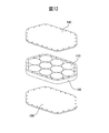
- an oxide superconducting bulk magnet having an aggregate of hexagonal columnar oxide superconducting bulk bodies in which a bulk body reinforcing member and an aggregate side surface reinforcing member are arranged, and a through-hole is formed in the oxide superconducting bulk body. It is a disassembled perspective view which shows the example which couple
- an oxide superconducting bulk magnet having an aggregate of hexagonal columnar oxide superconducting bulk bodies in which a bulk body reinforcing member and an aggregate side surface reinforcing member are arranged, It is a disassembled perspective view which shows the example which extended the edge part so that the side surface of an aggregate
- oxide superconducting bulk magnet according to the present embodiment (hereinafter also simply referred to as “superconducting bulk magnet”) will be described.
- the oxide superconducting bulk body (hereinafter also simply referred to as “superconducting bulk body”) used in the oxide superconducting bulk magnet according to the present embodiment is RE 2 BaCuO 5 in single-crystal REBa 2 Cu 3 O 7-x.
- a bulk material (so-called QMG (registered trademark) material) having a structure in which a non-superconducting phase typified by a phase (211 phase) is finely dispersed is desirable.
- QMG registered trademark
- single crystal form means that it does not have to be a perfect single crystal, and includes a defect having a defect that may be practically used, such as a low-angle grain boundary.
- the RE in the REBa 2 Cu 3 O 7-x phase (123 phase) and the RE 2 BaCuO 5 phase (211 phase) is Y, La, Nd, Sm, Eu, Gd, Dy, Ho, Er, Tm, Yb, Lu.
- the 123 phase containing La, Nd, Sm, Eu, and Gd is out of the 1: 2: 3 stoichiometric composition, and Ba is partially substituted at the RE site.
- the 211 phase which is a non-superconducting phase La and Nd are somewhat different from Y, Sm, Eu, Gd, Dy, Ho, Er, Tm, Yb and Lu, and the ratio of metal elements is non-stoichiometric. It is known that it has a theoretical composition or a different crystal structure.
- substitution of the Ba element described above tends to lower the critical temperature. Further, in an environment with a lower oxygen partial pressure, substitution of Ba element tends to be suppressed.
- the 123 phase is a peritectic reaction between the 211 phase and a liquid phase composed of a composite oxide of Ba and Cu.
- the temperature at which the 123 phase is formed by this peritectic reaction (Tf: 123 phase formation temperature) is substantially related to the ionic radius of the RE element, and Tf also decreases as the ionic radius decreases. Further, Tf tends to decrease with the addition of a low oxygen atmosphere and Ag.
- a material in which the 211 phase is finely dispersed in the single crystal 123 phase is formed because 211 unreacted grains are left in the 123 phase when the 123 phase is crystal-grown. That is, the bulk material is 211 phase + liquid phase (complex oxide of Ba and Cu) ⁇ formed by a reaction represented by 123 phase + 211 phase.
- Finely dispersed in 211 phase in the bulk material is extremely important in view of the critical current density J c improved.
- a trace amount of at least one of Pt, Rh, or Ce the grain growth of the 211 phase in the semi-molten state (a state composed of the 211 phase and the liquid phase) is suppressed, and as a result, the 211 phase in the material is reduced to about The size is reduced to about 1 ⁇ m.
- the addition amount is 0.2 to 2.0% by mass for Pt, 0.01 to 0.5% by mass for Rh, and 0.5 to 2.0% for Ce from the viewpoint of the amount of the effect of miniaturization and the material cost. The mass% is desirable.
- the added Pt, Rh, and Ce partially dissolve in the 123 phase.
- elements that could not be dissolved form a composite oxide with Ba and Cu and are scattered in the material.
- the bulk oxide superconductor constituting the magnet needs to have a high critical current density ( Jc ) even in a magnetic field.
- Jc critical current density
- the phase is a single-crystal 123 phase that does not include large-angle grain boundaries that are superconductively weakly coupled.
- a pinning center for stopping the movement of magnetic flux is required. What functions as the pinning center is a finely dispersed 211 phase, and it is desirable that many finely dispersed.
- Pt, Rh, and Ce have a function of promoting the refinement of the 211 phase.
- the non-superconducting phase such as the 211 phase has an important function of mechanically strengthening the superconductor and forming a bulk material by being finely dispersed in the 123 phase that is easy to cleave.
- the proportion of the 211 phase in the 123 phase is preferably 5 to 35% by volume from the viewpoint of Jc characteristics and mechanical strength.
- the material generally contains 5 to 20% by volume of voids (bubbles) of about 50 to 500 ⁇ m.
- voids bubbles
- the oxygen deficiency (x) of the material after crystal growth is about 0.5, indicating a temperature change in semiconductor resistivity. This is annealed in an oxygen atmosphere at 350 ° C. to 600 ° C. for about 100 hours by each RE system, so that oxygen is taken into the material, and the amount of oxygen deficiency (x) is 0.2 or less, resulting in excellent superconducting characteristics. Show. At this time, a twin structure is formed in the superconducting phase. However, including this point, it is referred to as a single crystal here.
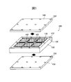
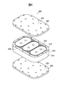
- FIG. 1 is a schematic exploded perspective view showing an example of a superconducting bulk magnet.
- each rectangular superconducting bulk body 12 is surrounded by a thick metal reinforcing body 14.
- the superconducting bulk body 12 has a discrete arrangement, and the effect of integrating a plurality of superconducting bulk bodies 12 is small.
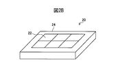
- the superconducting bulk magnet 20 shown in FIG. 2B a plurality of superconducting bulk bodies 22 are densely arranged, and the outer periphery of the aggregate is surrounded by a thick metal reinforcing body 24.
- Such a configuration can be expected to increase the overall magnetic field strength and the total amount of magnetic flux per unit area as compared to FIG. 2A.
- the superconducting bulk body 22 constituting the aggregate in the process of magnetization There is a problem that some things break.
- the thickness of the reinforcing frame provided on the side surface of each superconducting bulk body is preferably 5.0 mm or less, 3.0 mm or less is more preferable, and 1.0 mm or less is more preferable.
- a bulk body reinforcing member is installed on each side surface of each superconducting bulk body, an assembly side surface reinforcing member is arranged on the side surface of the superconducting bulk body assembly, and superconducting is further performed.
- a reinforcing member that covers the entire upper surface and lower surface of the bulk assembly is provided. That is, as shown in FIG. 1, in the superconducting bulk magnet 100 according to the present embodiment, the bulk body reinforcing member 120 is fitted to the side surface of each superconducting bulk body 110, and a plurality of these are arranged on the side surface of the aggregate.
- the assembly side surface reinforcing member 130 is disposed, the assembly upper reinforcing member 140 and the assembly lower reinforcing member 150 are applied to the upper surface and the lower surface of the assembly, and are fastened through coupling members (not shown) at a plurality of surrounding locations.
- the assembly side reinforcing member 130, the assembly upper reinforcing member 140, and the assembly lower reinforcing member 150 are fixed so as to be integrated.
- FIG. 1 shows the case where there are six superconducting bulk bodies 110 (hereinafter referred to as “bulk body units”) to which the bulk body reinforcing member 120 is fitted, the present invention is an example of this. It is not limited to. For example, when the number of bulk body units is 5, 7 or the like, the operational effects of the present invention are also effective.
- the bulk body reinforcing member 120 is a hollow member along the side surface shape of the superconducting bulk body 110, and is provided on each side surface of each superconducting bulk body 110.
- the bulk body reinforcing member 120 compresses and reinforces the side surface of each oxide superconducting bulk body 110 during cooling.
- the effect of suppressing cracking can be achieved against the hoop stress of each oxide superconducting bulk body 110.
- each superconducting bulk body 110 is exposed from the bulk body reinforcing member 120 even when the bulk body reinforcing member 120 is provided.
- the bulk body reinforcing member is thick.
- the bulk body reinforcing member is preferably thin.
- the bulk body reinforcing member 120 is preferably 5.0 mm or less, more preferably 3.0 mm or less, as described above, in order to maintain the magnetic field strength required for the superconducting bulk magnet 100 and the total amount of magnetic flux per unit area. More preferably, the thickness is 1.0 mm or less.
- the material of the bulk body reinforcing member 120 it is preferable to use stainless steel, titanium alloy, copper alloy, aluminum alloy or the like having sufficient strength. The lower limit value of the thickness of the bulk body reinforcing member 120 is determined according to the strength of these materials.
- the bulk reinforcing member can be produced by ordinary metal processing such as lathe, machining center, electric discharge machining. Further, the joining of the oxide superconducting bulk body and the bulk body reinforcing member can be performed by resin bonding, solder bonding, grease bonding, or the like. In addition, as described above, the bulk body reinforcing member prevents the breakage because it can relieve excessive force acting locally on some of the oxide superconducting bulk bodies because the gaps are not uniformly formed. There is also an effect.
- the bulk body reinforcing member of each superconducting bulk body when the bulk body reinforcing member of each superconducting bulk body is removed and used, the superconducting bulk body is broken.
- the bulk body reinforcing member provided on the side surface of the superconducting bulk body has an effect of relaxing such stress.
- a plurality of bulk body units are arranged to form an aggregate.
- the directions of the upper surfaces of the respective superconducting bulk bodies 110 are aligned in the same direction, and the bulk body reinforcing members 120 of the adjacent superconducting bulk bodies 110 are brought into contact with each other to form an aggregate.
- six superconducting bulk bodies 110 provided with bulk body reinforcing members 120 may be arranged in a 2 ⁇ 3 array to form an aggregate.
- the aggregate is regulated by contacting the side surface of the aggregate with the inner peripheral surface of the aggregate side surface reinforcing member 130 corresponding to the shape of the side surface.
- the aggregate side surface reinforcing member 130 is formed thicker than the bulk body reinforcing member, and has a thickness of, for example, 5 mm or more, and is appropriately determined in consideration of the overall size of the superconducting bulk magnet. Furthermore, it is necessary for securing the strength that the aggregate side surface reinforcing member 130 is connected to both the aggregate upper reinforcing member 140 and the aggregate lower reinforcing member 150. This is particularly necessary to cope with bending and twisting stresses. However, it is not necessary to be connected over the entire circumference of the side surface, and the proportion of the portions connected in the circumferential direction may be 50% or more, preferably 70% or more, more preferably 90% or more, and further 100%. preferable. Furthermore, the height of the portion in contact with the side surface of the aggregate in the aggregate side surface reinforcing member 130 needs to be equal to or higher than the height of the aggregate, that is, the height of the bulk unit.
- the assembly side surface reinforcing member 130 includes the assembly upper side reinforcing member 140 and the assembly lower side reinforcing member. This is because it cannot be connected to 150 and sufficient bond strength cannot be obtained. Therefore, it is preferable that the height of the portion in contact with the side surface of the aggregate in the aggregate side surface reinforcing member 130 is substantially the same as the height of the aggregate, that is, the height of the bulk unit. Further, the assembly side surface reinforcing member 130 may be higher than the bulk unit.
- a gap is formed between the upper surface of the bulk unit and the lower surface of the assembly upper reinforcing member 140, or between the lower surface of the bulk unit and the upper surface of the assembly lower reinforcing member 140. It may be filled with resin, grease or the like. However, if the gap is too high, the bulk body unit may not be sufficiently fixed, so that any of the gaps is preferably 10 mm or less, and more preferably 1 mm or less. Further, the bulk unit may be exposed by an opening or the like of a part of the aggregate side surface reinforcing member.
- the side surface of the assembly is covered with the assembly side surface reinforcing member, and the upper surface and the lower surface of the assembly are covered with the assembly upper reinforcing member and the assembly lower reinforcing member, respectively.
- the side reinforcing member, the assembly upper reinforcing member, and the assembly lower reinforcing member are integrated.
- the material of the aggregate side surface reinforcing member 130 is not particularly limited, and may be the same as or different from, for example, the bulk body reinforcing member 120. Specifically, stainless steel, titanium alloy, copper alloy, and aluminum alloy having sufficient strength are preferable.
- the assembly reinforcement can be produced by ordinary metal processing such as a lathe, a machining center, or electric discharge machining. Furthermore, these members and the bulk unit can be joined by, for example, resin bonding, solder bonding, grease bonding, or the like. In order to fill the gap between these members and the bulk unit, it is effective to fill with resin, solder, grease or the like.
- An assembly upper reinforcing member 140 and an assembly lower reinforcing member 150 are further fixed to the upper and lower surfaces of the assembly of bulk unit units surrounded and integrated by the assembly side reinforcing member 130.
- the Specifically, the assembly upper reinforcement member 140 and the assembly lower reinforcement member 150 are provided on the assembly side reinforcement member in order to prevent the stress from being released from the point that the stress is locally concentrated on the assembly. It is fixed so as to be integrated.
- the thickness of the aggregate upper surface reinforcing member and the aggregate lower surface reinforcing member is desirably 2 mm or more, and is preferably greater than the thickness of the bulk body reinforcing member.
- the fixing means is not particularly limited as long as the aggregate side surface reinforcing member 130 and the reinforcing plates 140 and 150 are fixed so as to be integrated.
- a fastening member such as a bolt may be used, or an adhesive means such as soldering may be used.
- the oxide superconducting bulk material may be housed in a container in which the assembly side reinforcing member and the assembly lower reinforcing member are integrated, and the assembly upper reinforcing member may be fixed to the container.
- the fixing means described above may be used.
- a container in which the assembly side reinforcing member and the assembly upper reinforcing member are integrally formed is placed on the oxide superconducting bulk body disposed on the assembly lower reinforcing member, and the container and the assembly lower reinforcing member are covered. And may be fixed.
- the fixing means described above may be used as a means for fixing the container and the lower assembly reinforcing member.
- the assembly side surface reinforcing member and the upper and lower surface reinforcing members are integrated by fastening with a coupling member (not shown) such as a bolt. Therefore, a plurality of fastening holes 132, 142, and 152 are formed at positions where bolts are inserted in the upper and lower surfaces of the assembly side surface reinforcing member 130, the assembly upper reinforcing member 140, and the assembly lower reinforcing member 150, respectively.
- the bolt diameter, the bolting arrangement interval, the bolt interval, and the like are design matters, and may be appropriately designed so that sufficient strength can be obtained according to the shape and size of the oxide superconducting bulk magnet 100.
- the fastening holes 132 are formed at a total of 10 locations including the four corners and the positions where the adjacent superconducting bulk bodies 110 are in contact with the upper surface and the lower surface of the assembly side surface reinforcing member 130.
- the fastening holes 142 and 152 are formed as through holes at positions corresponding to the fastening holes 132 on the upper surface and the lower surface of the aggregate side surface reinforcing member 130, respectively.
- two through holes are formed in addition to the outer peripheries of the assembly upper reinforcing member 140 and the assembly lower reinforcing member 150. An example of using these through holes will be described later.
- the superconducting bulk magnet 100 reinforces an assembly formed by arranging a plurality of bulk body units so as to be in contact with each other by the assembly side surface reinforcing member 130, The lower surface is covered with the assembly upper reinforcing member 140 and the assembly lower reinforcing member 150 and fixed to the assembly side reinforcing member 130 to be integrated.
- the bulk body reinforcing member 120 and the aggregate side surface reinforcing member 130 cause an excessive force to locally act on some superconducting bulk bodies 110 constituting the aggregate. Can be prevented. As a result, it is possible to prevent damage to all superconducting bulk bodies 110 constituting the superconducting bulk magnet.
- the oxide superconducting bulk magnet of the present invention when applied to a rotating device or the like, a situation occurs in which the configuration of the assembly upper reinforcing member and the assembly lower reinforcing member is not necessarily vertically symmetric. Specifically, the situation is such that the space is cooled from the assembly lower reinforcement member side of the bulk magnet to generate a magnetic field, and the magnetic field generated on the assembly upper reinforcement member side is used.
- the assembly lower reinforcing member is made of, for example, an oxygen-free copper plate having good thermal conductivity
- the assembly upper surface reinforcing member is made of a nonmagnetic material that does not interfere with the magnetic field, such as a stainless steel plate.
- the oxygen expansion copper and stainless steel also have different coefficients of thermal expansion and mechanical strength, so that the oxide superconducting bulk magnet tends to be bent in addition to the force to spread the bulk reinforcing member outward. Power and power to twist are working.
- the assembly side surface reinforcing member 130 can be firmly fixed so as to be integrated with the assembly upper reinforcing member 140 and the assembly lower reinforcing member 150. It is valid. This will be described in more detail below.
- the superconducting bulk magnet according to the present embodiment places importance on application to magnetic poles of rotating equipment such as generators and motors.
- the magnetic flux generated by the oxide superconducting bulk magnet attached to the rotor is efficiently linked with the winding of the stator located outside the rotor (on the assembly upper surface reinforcing plate side). There is a need.
- the assembly lower reinforcing member which is a surface attached to the rotor, be made of a material having good thermal conductivity.
- the gap between the oxide superconducting bulk magnet and the winding surface on the stator side needs to be reduced to the order of several mm.
- the material of the upper assembly reinforcing member is different from the material of the lower assembly reinforcing member, and the lower assembly reinforcing member is made of a material having a thermal conductivity of 50 W / m ⁇ K or more. Is preferred. Specifically, copper, a copper alloy, aluminum, and an aluminum alloy are preferable.
- the assembly upper reinforcing member is required to have higher strength than the assembly lower reinforcing member.
- the yield strength at room temperature (300K) is preferably 200 MPa or more.
- Specific examples of the material include stainless steel, titanium alloy, copper alloy, and aluminum alloy.
- the assembly upper reinforcing member and the assembly lower reinforcing member can be produced by ordinary metal processing such as lathe, machining center, electric discharge machining and the like. Furthermore, these members and the bulk unit may be joined by, for example, resin bonding, solder bonding, grease bonding, or the like. In order to fill the gap between these members and the bulk unit, it is effective to fill with resin, solder, grease or the like.
- the inventors of the present application further more reliably and effectively prevent the influence of bending and twisting forces acting on the bulk magnet due to the different materials of the upper assembly reinforcing member and the lower assembly reinforcing member.
- the upper assembly reinforcement member and the lower assembly reinforcement member to the assembly side surface reinforcement member, the upper assembly reinforcement member and the assembly through the interior of the assembly as well as the planar outer periphery of the superconducting bulk magnet
- a fastening member such as a bolt inside the assembly.
- the aggregate of the superconducting bulk bodies according to the present embodiment is arranged densely with the bulk body reinforcing members between the individual superconducting bulk bodies in order to ensure a sufficient total magnetic flux amount in a limited area.
- the oxide superconducting bulk body 210 is penetrated in the height direction.
- a through hole 212 is formed, and a through hole is also formed in the assembly upper reinforcing member 240 and the assembly lower reinforcing member 250 at a position corresponding to the through hole 212.
- the oxide superconducting bulk body 210, the assembly upper reinforcing member 240, and the assembly lower reinforcing member 250 can be fixed by fastening members such as bolts even at the positions of the through holes 212 of the oxide superconducting bulk body 210. it can. Therefore, as compared with the case where the assembly upper reinforcement member 140 and the assembly lower reinforcement member 150 are connected and fixed only through the assembly side reinforcement member 130 as shown in FIG. And can be fixed.
- the shape of the oxide superconducting bulk body that constitutes the superconducting bulk magnet in the present embodiment is not particularly limited, and for example, the oxide superconducting bulk body may have a triangular shape or more in a plan view.
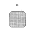
- FIG. 5 is a plan view showing an example in which the superconducting bulk body constituting the superconducting bulk magnet in the present embodiment is an octagon in plan view.
- each superconducting bulk body 110 is columnar, and as shown in FIG. 5, when viewed from the plane, the four corners are chamfered to form an octagon.
- the superconducting bulk body 110 according to the present embodiment has an octagonal shape by chamfering the four corners of the rectangle.
- the superconducting bulk body 110 used in the superconducting bulk magnet 100 according to the present embodiment is chamfered at the four corners. It may be a rectangular shape. It should be noted that stress generated from the repulsive force tends to concentrate at the four corners of the superconducting bulk body 110, and there is a possibility that cracks may occur from the portion where the stress is concentrated. By chamfering the side surface of the superconducting bulk body 110, a secondary effect of removing such a cracking factor can be obtained.
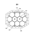
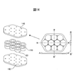
- FIG. 9 is a plan view showing an example in which the superconducting bulk body constituting the superconducting bulk magnet in the present embodiment has a hexagonal shape in plan view.
- the oxide superconducting bulk body By forming the oxide superconducting bulk body into a hexagonal column shape, a plurality of oxide superconducting bulk bodies can be arranged to form an aggregate without gaps. As a result, the overall magnetic field strength and the total magnetic flux per unit area can be sufficiently increased. Moreover, since it is closer to a cylinder than a quadrangular prism, the captured magnetic field characteristic is better than that of a quadrangular prism.
- the superconducting bulk body can be arranged without a gap to form an aggregate, when the aggregate upper reinforcing member and the aggregate lower reinforcing member are also fixed inside the bulk magnet, in order to form a gap, It is necessary to form holes in the oxide superconducting bulk body.
- the oxide superconducting bulk body may have a shape in plan view, in which a vertex of a polygon is rounded. That is, the corners of the polygon may be configured with a curve and may be rounded.
- the oxide superconducting bulk body may have a racetrack shape in which a pair of opposed parallel straight lines and a pair of opposed curved lines are connected in a plan view.
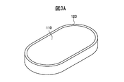
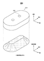
- FIG. 3A is a perspective view showing an example in which the superconducting bulk body constituting the superconducting bulk magnet in this embodiment is a racetrack type.
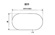
- FIG. 3B is an explanatory view for explaining the size of the racetrack superconducting bulk body shown in FIG. 3A.
- FIG. 6 is an exploded perspective view showing an example of an oxide superconducting bulk magnet composed of a racetrack superconducting bulk body.
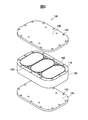
- FIG. 4 is an exploded perspective view showing an example of an oxide superconducting bulk magnet composed of a racetrack superconducting bulk body in which a through hole is formed as described above.
- the racetrack-type oxide superconducting bulk body 110 has an upper surface, a lower surface, and a side surface, and the side surface is connected to a pair of opposing parallel straight lines and a pair of opposing curves. It is formed in a racetrack shape.
- a race track type bulk body reinforcing member 120 is fitted to the side surface.
- the “longitudinal length” and “width” are defined as shown in FIG. 3B, with the linear direction when viewed from the top or bottom surface as the longitudinal direction.
- An oxide superconducting bulk magnet 100 shown in FIG. 6 includes an assembly formed by arranging a plurality of bulk body units each composed of a racetrack-type oxide superconducting bulk body 110 and a bulk body reinforcing member 120 so as to be in contact with each other.
- the oxide superconducting bulk magnet 200 shown in FIG. 4 has the same configuration as the oxide superconducting bulk magnet 100 shown in FIG. 6 except that through holes are formed in the oxide superconducting bulk body 210.
- the spacers 160 and 260 shown in FIG. 4 and FIG. 6 are provided for providing a place for fixing the upper assembly reinforcing members 140 and 240 and the lower assembly reinforcing members 150 and 250 in addition to the assembly side reinforcing members 130 and 230. It is.
- the spacer 260 may also be disposed in the through hole 212 of the oxide superconducting bulk body 210.
- the spacers 160 and 260 are formed with holes at the top or bottom in the height direction. This hole may be a through-hole penetrating vertically.
- the uniformity of the magnetic field distribution in the longitudinal direction is high.
- a superconducting bulk magnet composed of a plurality of oxide superconducting bulk bodies the magnetic field at the boundary of each oxide superconducting bulk body is reversed and non-uniform with respect to the magnetic field polarity at the center. Therefore, in the oxide superconducting bulk magnets 100 and 200 including the racetrack-type oxide superconducting bulk bodies 110 and 210 shown in FIGS. 6 and 4, a magnetic field distribution with high uniformity in the longitudinal direction can be obtained.
- the trapped magnetic flux distribution of one oxide superconducting bulk body varies depending on the magnetization conditions.
- a general superconducting bulk material in which RE 2 BaCuO 5 is dispersed in single crystal RE 1 Ba 2 Cu 3 O y at a liquid nitrogen temperature (77 K) is used, and a racetrack type is formed as shown in FIG.
- the critical current density is relatively low.
- the magnetic flux density distribution becomes a distribution shown in the lower side of FIG. 7, and the superconducting current flows through the entire bulk material.
- a through hole 212 is provided in the central portion of the racetrack-type oxide superconducting bulk body 210, and fixing means such as bolts are inserted into the through hole 212 to reinforce the upper portion of the assembly.
- fixing means such as bolts are inserted into the through hole 212 to reinforce the upper portion of the assembly.
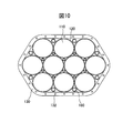
- the oxide superconducting bulk material may have a cylindrical shape.
- FIG. 10 is a plan view showing an example in which the superconducting bulk body constituting the superconducting bulk magnet in the present embodiment has a circular shape in plan view.
- the bulk body reinforcing member disposed on the side surface of the oxide superconducting bulk body applies isotropically high pressure to the oxide superconducting bulk body.
- the effect of reducing the hoop stress is high.
- the single crystal bulk material obtained by crystal growth has a cylindrical shape, it is easy to process and has little loss when processed into an oxide superconducting bulk body, so that the yield is good. Furthermore, it has excellent capture magnetic field characteristics.
- the assembly upper reinforcing member and the assembly lower reinforcing member are connected to the interior of the bulk magnet using the gap. Since it can also be fixed, it can sufficiently counteract the force to bend or twist the entire bulk magnet.
- the oxide superconducting bulk magnets 100 and 200 according to the present embodiment which are composed of the above-described oxide superconducting bulk body, are excellent as magnetic poles for rotating devices such as generators and motors as described above.
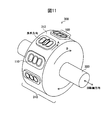
- FIG. 11 shows a configuration example of a rotating device 300 using an oxide superconducting bulk magnet 100 using a racetrack-type oxide superconducting bulk body 110 as a magnetic pole.
- FIG. 11 shows a state in which the assembly upper reinforcing member that covers the upper surface of the assembly of the bulk unit is removed.
- the rotating device 300 is formed by providing the oxide superconducting bulk magnet 100 as magnetic poles at predetermined intervals on the outer peripheral surface of a disk-like rotor 310 that rotates about a rotating shaft 320.
- the oxide superconducting bulk magnet 100 is firmly connected to the outer peripheral portion of the rotor 310 with a bolt or the like. If necessary, a high heat conductive member such as copper or aluminum for cooling the oxide superconducting bulk body 110 may be used for the lower assembly reinforcing member and connected so that an appropriate amount of cold heat from the refrigerant can be transmitted. .
- the longitudinal direction of the racetrack-type oxide superconducting bulk body 110 coincides with the rotational movement direction A of the rotor 310. That is, the longitudinal direction of the oxide superconducting bulk body 110 is perpendicular to the rotation axis 320.
- the stator (not shown) facing the magnetic pole is substantially constant while one magnetic pole passes. If the rotation speed is constant, a substantially constant magnetomotive force can be generated.
- the longitudinal direction of the oxide superconducting bulk body 110 is parallel to the rotation axis direction, a plurality of magnetic flux density peaks can be experienced while one magnetic pole passes.
- the fact that the magnetic flux density is constant means that the harmonic component is suppressed in the case of a generator, and the cogging torque can be suppressed in the case of a motor to enable smooth rotation. Therefore, the fact that the magnetic flux density is constant is a great merit of the magnetic pole using the racetrack oxide superconducting bulk body 110.
- the superconducting bulk magnet is attached as a magnetic pole to a rotating device or the like with the assembly lower reinforcing member.
- the rotating device or the like is provided with a cooling plate made of oxygen-free copper, for example, as a magnetic pole mounting surface
- the superconducting bulk magnet may not have the assembly lower reinforcing member. That is, if the superconducting bulk magnet that does not have the assembly lower reinforcement member is attached to the cooling plate of the rotating device and fixed so as to be integrated, the structure of the superconducting bulk magnet described above can be obtained by including the cooling plate. realizable. Therefore, the assembly lower reinforcing member may be a mounting surface of a magnetic pole of a rotating device or the like.
- the assembly upper reinforcing member may have a curved surface.
- the outer diameter of the rotor when relatively small, it may have a curvature that matches the shape of the inner peripheral curved surface on the stator side.
- the plane on the assembly upper reinforcing member side of each oxide superconducting bulk body is along this curve (that is, the plane on the assembly upper reinforcing member side of the central oxide superconducting bulk body is
- the oxide superconducting bulk body may be disposed so that it protrudes from the plane on the assembly upper reinforcing member side to the assembly upper reinforcing member side.
- the side surface of the assembly is in contact with only a part of the assembly side surface reinforcing member, and a gap is generated between the inner peripheral surface of the assembly side surface reinforcing member and the side surface of the assembly.
- Example 1 In the superconducting bulk magnet of this example, a Gd—Ba—Cu—O-based oxide superconducting bulk body was used.
- Gd gadolinium
- Ba barium
- Cu copper
- the weighed powder was sufficiently kneaded for 1 hour and then calcined at 1173K for 8 hours in the air.
- the calcined powder was formed into a disk shape using a mold.
- This molded body was heated to 1423K to be melted and held for 30 minutes, and then seeded in the middle of temperature reduction, and the temperature range from 1278K to 1252K was gradually cooled over 100 hours to grow a crystal.
- a superconducting bulk material was obtained.
- This single crystal superconducting bulk body was chamfered into the shape shown in FIG. 5 to form an octagonal shape with a side of 50 mm and a height of 20 mm, and heat-treated at 723 K for 100 hours in an oxygen stream.
- superconducting bulk bodies fitted with bulk body reinforcing members are arranged in a rectangular shape with a total of 6 pieces of 3 ⁇ 2 pieces, and the whole is a stainless steel having a thickness of 5 mm and a height of 20 mm. It was surrounded by an assembly side reinforcing member made of steel SUS316L. At this time, the superconducting bulk body, the bulk body reinforcing member, and the aggregate side surface reinforcing member were bonded to each other with an epoxy resin (trade name: Stycast 2850FT, manufactured by Nippon Able Stick Co., Ltd.) so as not to shift during the magnetization experiment. .
- an epoxy resin trade name: Stycast 2850FT, manufactured by Nippon Able Stick Co., Ltd.
- an oxygen-free copper plate as an assembly lower reinforcement member is arranged on the lower surface of the assembly, and a stainless steel SUS316L plate as an assembly upper reinforcement member is arranged on the upper surface, and a total of 10 locations are bolted on the assembly side reinforcement member.
- the assembly side reinforcing member, the assembly upper reinforcing member, and the assembly lower reinforcing member were fixed so as to be integrated. In cases 1-A to 1-D, two bolts were further tightened inside the assembly.
- Table 2 shows a comparison of cases 1-B to 1-D with the total magnetic flux of the superconducting bulk magnet of case 1-A as a reference under the magnetization condition of the external magnetic field 4T.
- cases 1-B and 1-C where the thickness of the bulk reinforcing member is 1 mm or less, it was confirmed that the total magnetic flux amount was 90% or more.
- the number of damaged oxide superconducting bulk bodies was shown under the condition of an external magnetic field of 5T. From the results of this experiment, it was shown that in a superconducting bulk magnet in which the upper assembly reinforcing member and the lower assembly reinforcing member are fixed inside the assembly, the superconducting bulk body can be prevented from being damaged and a strong magnetic field can be generated. .
- Example 2 The test similar to Example 1 was implemented about the case where a total of 4 superconducting bulk bodies of 2 ⁇ 2 were combined.
- cases 2-A to 2-D in Table 3 bolts were fastened to one of the inner portions of the superconductor bulk magnet on the assembly side surface reinforcing member in addition to the plane outer periphery at eight locations.
- case 2-E as an example of the present invention, internal bolting was not performed.
- Table 3 shows a comparison of cases 2-B to 2-E based on the total magnetic flux of the superconducting bulk magnet of case 2-A under the magnetization condition of the external magnetic field 4T.
- cases 2-B to 2-D as examples of the present invention the superconducting bulk material was not damaged.
- case 2-A which is a comparative example in which no bulk body reinforcing member was fitted into each superconducting bulk body, three superconducting bulk bodies were damaged.
- case 2-E which is an example of the present invention, one superconducting bulk material was damaged.
- Example 3 the superconducting bulk magnet having the racetrack-type oxide superconducting bulk body shown in FIG. 3A was verified.
- a Gd (Dy) -Ba-Cu-O-based oxide superconducting bulk body was used.
- a rare earth element (RE), barium (Ba), and copper (Cu) oxide powder each having a purity of 99.9% by mass is commercially available.
- RE: Ba: Cu 1.6: 2.3: Weighed at a molar ratio of 3.3, and added 1.5 wt% BaCeO 3 and 20 wt% silver.
- the weighed powder was sufficiently kneaded for 1 hour and then calcined at 1173K for 8 hours in the air.
- These calcined powders are concentrically placed in a mold having a diameter of 200 mm, and (100: 0) calcined powder is arranged in a 50 mm diameter region, and (95: 5) provisional name powder is placed in a region having a diameter of 100 mm.
- (90:10) calcined powder was arranged in a region of 150 mm around the periphery, and the rest (85:15) calcined powder was arranged and pressure-molded.
- This molded body was heated to 1423K to be melted and held for 30 minutes, and then seeded in the middle of temperature reduction, and the temperature range of 1278K to 1252K was gradually cooled over 300 hours to grow crystals.
- An oxide superconducting bulk material was obtained.
- the single-crystal oxide superconducting bulk material thus produced was processed into a racetrack type (longitudinal length 120.0 mm, width 60.0 mm, height 20.0 mm), and 100 at 723 K in an oxygen stream. Heat treated for hours.
- This racetrack type oxide superconducting bulk body is made of a racetrack type bulk body reinforcing member made of stainless steel SUS316L (longitudinal length of outer circumference 122.0 mm, width 62.0 mm, longitudinal length of inner circumference 120.0 mm). , Width 60.0 mm, height 20.0 mm, wall thickness 1.0 mm) were fitted and fixed with resin. Further, two racetrack-type oxide superconducting bulk bodies with a bulk body reinforcing member produced in the same manner were produced, and these three pieces were spread, and the entire side reinforcement of the aggregate formed from the same stainless steel SUS316L having a thickness of 10 mm. It was enclosed by a member (longitudinal length 206 mm of outer circumference, 142 mm width, longitudinal length 186 mm of inner circumference, width 122 mm, height 20.0 mm, wall thickness 10 mm).
- the upper and lower surfaces of the bulk unit surrounded by the assembly side reinforcement members are stainless steel SUS316L assembly upper reinforcement members and assembly lower reinforcement members having holes for screwing (the outer shape is the assembly side surface).
- resin trade name: Stycast 2850FT, manufactured by Nippon Able Stick Co., Ltd.
- resin (trade name: Stycast 2850FT, manufactured by Nippon Able Stick Co., Ltd.) is used so that the oxide superconducting bulk body, the bulk body reinforcing member, and the aggregate side surface reinforcing member do not shift during the magnetization experiment. Embedded in.
- an oxide superconducting bulk magnet in which the thickness of the bulk body reinforcing member is zero that is, no bulk body reinforcing member
- Comparative Example 3-A A bulk body reinforcing member having an oxide superconducting bulk magnet with a thickness of 0.5 mm (Example 3-B), an oxide superconducting bulk magnet with a thickness of 1.0 mm (Example 3-C), and having a thickness of 2.0 mm The oxide superconducting bulk magnet (Example 3-D) was verified. These were produced in the same manner except for the thickness of the bulk reinforcing member.
- Table 4 shows a comparison with the total magnetic flux of the oxide superconducting bulk magnet of Comparative Example 3-A as a reference under the magnetization condition of the external magnetic field 5T, and cracking of the oxide superconducting bulk body when the external magnetic field 5T is magnetized. Indicates the presence or absence of In Table 4, when one or more oxide superconducting bulk bodies were damaged under the condition of an external magnetic field of 5T, the damage was judged as “present”. When the thickness of the bulk reinforcing member was 1 mm or less, it was confirmed that the total magnetic flux amount was 90% or more.
- these oxide superconducting bulk magnets were magnetized by cooling in a magnetic field at about 30 K using a refrigerator, and the magnetic field distribution was measured. Under the condition of an external magnetic field of 4T, no damage was observed in any oxide superconducting bulk magnet. Next, when the external magnetic field was changed to 5T, the oxide superconducting bulk bodies of the oxide superconducting bulk magnets of Examples 3-B to 3-D were not damaged at all. The bulk magnet is damaged.
- the oxide superconducting bulk magnet formed by combining a plurality of racetrack type superconducting bulk bodies having the structure of the present invention the oxide superconducting bulk body is prevented from being damaged and a strong magnetic field is generated. It is possible to provide an oxide superconducting bulk magnet. Moreover, it was shown that a high total magnetic flux amount can be obtained by setting the thickness of the bulk body reinforcing member to 1.0 mm or less.
- the side surface of the aggregate of oxide superconducting bulk bodies formed by combining a plurality of bulk body units each having a racetrack type bulk body reinforcing member fitted to the outer periphery of each of the racetrack type oxide superconducting bulk bodies. It has been clarified that the oxide superconducting bulk magnet is an excellent magnetic field generation source by arranging the assembly reinforcement on the outer periphery and arranging the reinforcement members on the upper and lower surfaces of the assembly.
- Example 4 an oxide superconducting bulk magnet composed of an oxide superconducting bulk body in which the through holes shown in FIG. 4 were formed was verified.
- a Gd (Dy) -Ba-Cu-O-based oxide superconducting bulk body was used.
- a rare earth element (RE), barium (Ba), and copper (Cu) oxide powder each having a purity of 99.9% by mass is commercially available.
- RE: Ba: Cu 1.8: 2.4: It was weighed at a molar ratio of 3.6, and 1.5% by mass of BaCeO 3 and 20% by mass of silver were added thereto.
- the weighed powder was sufficiently kneaded for 1 hour and then calcined at 1173K for 8 hours in the air.
- These calcined powders are concentrically placed in a mold having a diameter of 200 mm, and (100: 0) calcined powder is arranged in a 50 mm diameter region, and (96: 4) provisional name powder is placed around the 100 mm diameter region.
- the calcined powder of (92: 8) was arranged in the area of 150 mm around the periphery, and the calcined powder of (88:12) was arranged for the rest, followed by pressure molding.
- This molded body was heated to 1423K to be melted and held for 30 minutes, and then seeded in the middle of temperature reduction, and the temperature range of 1278K to 1252K was gradually cooled over 320 hours to grow crystals, and a single crystal shape having a diameter of 155 mm An oxide superconducting bulk material was obtained.
- the single-crystal oxide superconducting bulk body thus produced is processed into a racetrack type (longitudinal length 110.0 mm, width 70.0 mm, height 20.0 mm), and further the oxide superconducting bulk body Two through-holes having a diameter of 10.0 mm were formed in the center of the substrate at a center interval of 40 mm in the longitudinal direction. Thereafter, this was heat-treated at 723 K for 100 hours in an oxygen stream. Heat treatment was performed at 723 K for 100 hours in an oxygen stream.
- This racetrack type oxide superconducting bulk body is made of a stainless steel SUS316L racetrack type bulk body reinforcing member (longitudinal length of outer circumference 112.0 mm, width 72.0 mm, longitudinal length of inner circumference 110.0 mm). , Width 70.0 mm, height 20.0 mm, wall thickness 1.0 mm) were fitted and fixed with resin. Further, two racetrack-type oxide superconducting bulk bodies with a bulk body reinforcing member produced in the same manner were produced, and these three pieces were spread, and the entire side reinforcement of the aggregate formed from the same stainless steel SUS316L having a thickness of 12 mm. It was surrounded by members (longitudinal length of outer circumference 240 mm, width 136 mm, longitudinal length of inner circumference 216 mm, width 112 mm, height 20.0 mm, wall thickness 10 mm).
- an upper assembly reinforcing member made of stainless steel SUS316L (thickness 5.5 mm) having a hole for screwing was placed on the upper surface of the bulk unit surrounded by the assembly side reinforcing member, and screwed.
- an assembly lower reinforcement member made of oxygen-free copper (thickness: 9.0 mm) having a hole for screwing was placed on the lower surface of the bulk body unit surrounded by the assembly side surface reinforcement member, and screwed.
- the outer peripheral shape of the assembly upper reinforcing member and the assembly lower reinforcing member is the same as the outer peripheral shape of the assembly side reinforcing member.
- the oxide superconducting bulk body, the bulk body reinforcing member, and the aggregate side surface reinforcing member are mutually resin (trade name: Stycast 2850FT, manufactured by Nippon Able Stick Co., Ltd.). Embedded in.
- an oxide superconducting bulk magnet (Comparative Example 4-A) in which the thickness of the bulk body reinforcing member is zero (that is, no bulk body reinforcing member) is compared with the bulk.
- An oxide superconducting bulk magnet having a thickness of 1.0 mm (Example 4-C) was verified. These were produced in the same manner except for the thickness of the bulk reinforcing member.
- Example 5 the oxide superconducting bulk magnet composed of the columnar oxide superconducting bulk body shown in FIG. 10 was verified.
- a Gd—Ba—Cu—O-based oxide superconducting bulk body was used.
- calcined powders were weighed so that the molar ratio of 123: 211 was 3: 1, and further 10% by mass of silver oxide powder was added to prepare a mixed powder.
- the mixed powder is produced using a cylindrical mold having an inner diameter of 65 mm, and after heating the formed body to a semi-molten state, the seed crystal is brought into contact with 1313 K, and a temperature range of 1278 K to 1255 K is set. Slow cooling over 280 hours and crystal growth were performed to obtain a single-crystal oxide superconducting bulk body having a diameter of about 51 mm.
- a single crystal oxide superconducting bulk body having a diameter of about 51 mm was obtained by the same method, and then an oxide superconducting bulk body having a diameter of 47 mm and a height of 17 mm was produced.
- an oxide superconducting bulk body having a diameter of 38 mm and a height of 12 mm was produced.
- ten oxide superconducting bulk bodies having a diameter of 50 mm and a height of 17 mm produced by the same method were used and arranged as shown in FIG. At this time, there is no bulk reinforcing member.
- As the assembly side surface reinforcing member a ring made of SUS316L having a wall thickness of 12 mm and a height of 17 mm having a hole for screwing was used. Also, a 4.5 mm thick SUS316L plate having holes for screwing is used as the upper assembly reinforcing member, and a thickness of 11.0 mm having holes for screwing is used as the lower assembly reinforcing member.
- the oxide superconducting bulk magnet (5-A) of the comparative example was produced by using these oxygen-free copper plates and screwing them.
- FIG. 13 shows a cross-sectional view taken along the line A-A ′ and a cross-sectional view taken along the line B-B ′.
- An oxide-free superconducting bulk magnet (5-B) of the comparative example is used by using a plate made of oxygen-free copper having a thickness of 11.0 mm having a hole for screwing as a lower reinforcing member of the assembly, and screwing them. Produced.
- FIG. 14 also shows a cross-sectional view taken along the line A-A ′ and a cross-sectional view taken along the line B-B ′.
- An oxide-free superconducting bulk magnet (5-C) of the comparative example is used by using a plate made of oxygen-free copper with a thickness of 11.0 mm having a hole for screwing as a lower reinforcing member of the assembly and screwing them. Produced.
- ten oxide superconducting bulk bodies having a diameter of 47 mm and a height of 17 mm manufactured by the same method were used and arranged as shown in FIG.
- a copper alloy ring having an inner diameter of 47.05 mm and an outer diameter of 50.0 mm was used for the bulk body reinforcing member, and was bonded by soldering.
- As the assembly side surface reinforcing member a ring made of SUS316L having a thickness of 12 mm and a height of 17 mm having a hole for screwing was used.
- a 4.5 mm thick SUS316L plate having holes for screwing is used as the assembly upper reinforcing member, and a 11.0 mm thick wall having screws for fastening as the lower assembly reinforcing member.
- An oxide superconducting bulk magnet (5-D) of the example was produced by using oxygen-free copper plates and screwing them.
- ten oxide superconducting bulk bodies having a diameter of 47 mm and a height of 17 mm produced by the same method were used and arranged as shown in FIG.
- a copper alloy ring having an inner diameter of 47.05 mm and an outer diameter of 50.0 mm was used for the bulk body reinforcing member, and was bonded by soldering.
- As the assembly side surface reinforcing member a ring made of SUS316L having a thickness of 12 mm and a height of 17 mm having a hole for screwing was used.
- a 4.5 mm thick SUS316L plate having holes for screwing is used as the assembly upper reinforcing member, and a 11.0 mm thick wall having screws for fastening as the lower assembly reinforcing member.
- An oxygen-free copper plate was used.
- a spacer is arranged in the space between the columnar oxide superconducting bulk bodies with the bulk reinforcing member. Also in the position of, the strength was increased by bonding with a bonding member, and the oxide superconducting bulk magnet (5-E) of the example was manufactured.
- the shape of the outer periphery of the assembly upper reinforcement member and the assembly lower reinforcement member is 5-A assembly. It is the same as the shape of the outer periphery of the body side reinforcing member.
- the assembly upper reinforcement member and the assembly lower reinforcement member were solder-connected to the assembly side reinforcement member.
- the oxide superconducting bulk material and the aggregate side surface reinforcing member were embedded with a resin (trade name: Stycast 2850FT, manufactured by Nippon Able Stick Co., Ltd.) so as not to be displaced during the magnetization experiment.
- Table 5 shows the presence or absence of cracking of the oxide superconducting bulk body and the number of cracked columnar oxide superconducting bulk bodies under the magnetization conditions of each external magnetic field. Further, the result of measuring the amount of magnetic flux on one bulk body unit on the surface of the upper assembly reinforcing member when magnetized under the conditions of 30K and 2.5T is 100% based on Comparative Example 5-A. Indicates the value when. In addition, at 30K and 1.5T magnetization, there was no cracking of the oxide superconducting bulk material.
- Example 5-B Under the conditions of an external magnetic field of 30K and 3.0T, in Comparative Example 5-B, four oxide superconducting bulk bodies were damaged, but in other examples, there was no damage. Further, under the conditions of the external magnetic field of 30 K and 4.0 T, in Comparative Example 5-A, two oxide superconducting bulk bodies were damaged, but Comparative Example 5-C, Example 5-D, and Example 5 In -E, there was no damage. Further, under the conditions of the external magnetic field of 30 K and 6.0 T, in Example 5-D, one oxide superconducting bulk material was damaged, but in Example 5-E, there was no damage.
- Comparative Example 5-B had already been damaged in four bulk bodies. This is because in Comparative Example 5-B, in addition to the absence of the bulk body reinforcing member, only a part of the side surface of the assembly is covered. It will be applied to the superconducting bulk material. Since the oxide superconducting bulk material is a ceramic, the compressive strength is larger than the tensile strength, but it is basically a single crystal material, so it is easily chipped and easily broken by an external force. Therefore, it is considered that the aggregate upper reinforcing member could be fixed only with a force that does not damage the oxide superconducting bulk material.
- the amount of magnetic flux was reduced to 50% or less, and even the damaged oxide superconducting bulk body maintained a magnetic flux amount of about 70%. In the comprehensive judgment, it was determined that there was a decrease in the amount of magnetic flux at the same level. From these experimental results, in the oxide superconducting bulk magnet formed by combining a plurality of cylindrical superconducting bulk bodies having the structure of the present invention, the oxide superconducting bulk body is prevented from being damaged and a stronger magnetic field is generated. It was found that an oxide superconducting bulk magnet can be provided.
- Example 6 the oxide superconducting bulk magnet composed of the hexagonal column-shaped oxide superconducting bulk body shown in FIG. 9 was verified.
- a Dy—Ba—Cu—O-based oxide superconducting bulk body was used.
- calcined powders were weighed so that the molar ratio of 123: 211 was 3: 1, and further 10% by mass of silver oxide powder was added to prepare a mixed powder.
- the mixed powder is made into a molded body using a cylindrical mold having an inner diameter of 85 mm, and the molded body is heated to be in a semi-molten state. After contacting the seed crystal at 1313 K, a temperature range from 1263 K to 1240 K is set. The crystal was allowed to cool gradually over 320 hours to grow crystals, and a single crystalline oxide superconducting bulk body having a diameter of about 65 mm was obtained.
- hexagonal columnar oxide superconducting bulk bodies each having a side of 30 mm and a height of 20 mm manufactured by the same method were used and arranged as shown in FIG.
- a hexagonal columnar aluminum alloy ring having an inner peripheral side of 30.05 mm and an outer peripheral side of 32.0 mm was used for the bulk body reinforcing member and soldered thereto.
- As the assembly side reinforcing member a ring made of SUS314 having a thickness of 14 mm and a height of 20 mm having a hole for screwing was used.
- a 5.5 mm thick SUS314 plate having holes for screwing is used as the assembly upper reinforcing member, and a 12.0 mm thick wall having screws for fastening as the lower assembly reinforcing member.
- An oxide superconducting bulk magnet (6-B) of the example was manufactured by using oxygen-free copper plates and screwing them.
- hexagonal column-shaped oxide superconducting bulk bodies each having a side of 30 mm and a height of 20 mm were prepared in the same manner, and 2 of these were drilled with a diameter of 12 mm in the center. Then, they were arranged as shown in FIG. At this time, a hexagonal columnar aluminum alloy ring having an inner peripheral side of 30.05 mm and an outer peripheral side of 32.0 mm was used for the bulk body reinforcing member and soldered thereto.
- As the assembly side reinforcing member a ring made of SUS314 having a thickness of 14 mm and a height of 20 mm was used.
- a 5.5 mm thick SUS314 plate having holes for screwing is used as the upper assembly reinforcing member, and a 15.0 mm thick wall having holes for screwing is used as the lower assembly reinforcing member.
- an oxygen-free copper plate is used, and when the assembly upper reinforcement member and the assembly lower reinforcement member are joined via the assembly side reinforcement member, between the hexagonal columnar oxide superconducting bulk bodies with bulk reinforcement members Spacers were placed in the spaces.
- a spacer was also arranged in the hole of the hexagonal columnar oxide superconducting bulk body that had been drilled, and the assembly upper reinforcing member and the assembly lower reinforcing member were fixed via the spacer. Even at these positions, the strength was increased by bonding with a bonding member, and the oxide superconducting bulk magnet (6-C) of the example was manufactured.
- hexagonal column-shaped oxide superconducting bulk bodies each having a side of 30 mm and a height of 20 mm were prepared in the same manner, and 2 of these were drilled with a diameter of 12 mm in the center. Then, they were arranged as shown in FIG. At this time, a hexagonal columnar aluminum alloy ring having an inner peripheral side of 30.05 mm and an outer peripheral side of 32.0 mm was used for the bulk body reinforcing member and soldered thereto.
- As the assembly side reinforcing member a ring made of SUS314 having a thickness of 14 mm and a height of 20 mm was used.
- the assembly upper reinforcing member has a hole for screwing, and is processed so as to correspond to the shape of the end of the assembly of oxide superconducting bulk bodies (bulk body unit).
- An oxygen-free copper ring was used. That is, the edge part on the aggregate side of the aggregate side surface reinforcing member is extended so as to be in contact with the side surface of the aggregate.
- an oxygen-free copper plate having a wall thickness of 15.0 mm having holes for screwing is used, and the assembly upper reinforcement member and the assembly lower reinforcement member are interposed via the assembly side reinforcement member.
- spacers were also arranged in the holes of the two hexagonal columnar oxide superconducting bulk bodies that had been drilled, and the assembly upper reinforcing member and the assembly lower reinforcing member were fixed via the spacers. Even at these positions, the strength was increased by bonding with a bonding member, and an oxide superconducting bulk magnet (6-D) of an example was manufactured.
- the outer periphery shape of the assembly upper reinforcement member and the assembly lower reinforcement member is the outer periphery shape of the assembly side surface reinforcement member. Is the same. Also, before screwing, the oxide superconducting bulk body, the bulk body reinforcing member, and the aggregate side surface reinforcing member are embedded with a resin (trade name: Stycast 2850FT, manufactured by Able Stick Japan Co., Ltd.) so that they do not shift during the magnetization experiment. It is.
- a resin trade name: Stycast 2850FT, manufactured by Able Stick Japan Co., Ltd.
- Table 6 shows the presence or absence of cracking of the oxide superconducting bulk body and the number of cracked hexagonal columnar oxide superconducting bulk bodies under the magnetization conditions of each external magnetic field.
- Table 6 shows the presence or absence of cracking of the oxide superconducting bulk body and the number of cracked hexagonal columnar oxide superconducting bulk bodies under the magnetization conditions of each external magnetic field.
- two oxide superconducting bulk bodies were damaged in Comparative Example 6-A under the conditions of an external magnetic field of 40 K and 4.0 T, but Example 6-B, Example 6-C, In Example 6-D, there was no damage. Further, under the conditions of the external magnetic field of 40 K and 6.0 T, in Example 6-B, the two oxide superconducting bulk bodies were damaged, but in Example 6-C and Example 6-D, the damage was broken. There was no.
- oxide superconducting bulk magnet formed by combining a plurality of hexagonal column-shaped superconducting bulk bodies having the structure of the present invention, it is possible to prevent the oxide superconducting bulk body from being damaged and generate a stronger magnetic field. It was found that an oxide superconducting bulk magnet can be provided.
Landscapes
- Chemical & Material Sciences (AREA)
- Engineering & Computer Science (AREA)
- Organic Chemistry (AREA)
- Power Engineering (AREA)
- Ceramic Engineering (AREA)
- Inorganic Chemistry (AREA)
- Manufacturing & Machinery (AREA)
- Materials Engineering (AREA)
- Structural Engineering (AREA)
- Inorganic Compounds Of Heavy Metals (AREA)
- Superconductors And Manufacturing Methods Therefor (AREA)
Abstract
Description
前記酸化物超電導バルク体と、前記酸化物超電導バルク体の側面を覆うように配置されたバルク体補強部材と、からなるバルク体ユニットが、同一方向を向き、かつ互いに接するように配置されて集合体を形成し、
前記集合体の側面は、集合体側面補強部材により覆われており、
前記集合体の上面および下面は、それぞれ、集合体上部補強部材および集合体下部補強部材により覆われており、
前記集合体側面補強部材と前記集合体上部補強部材と前記集合体下部補強部材とが一体化された構成を有することを特徴とする酸化物超電導バルクマグネット。
(2)前記バルク体補強部材は、肉厚が5.0mm以下であることを特徴とする(1)に記載の酸化物超電導バルクマグネット。
(3)前記集合体上部補強部材を構成する材質と、前記集合体下部補強部材を構成する材質とが異なり、前記集合体上部補強部材は前記集合体下部補強部材よりも300Kにおける降伏強度が高く、前記集合体下部補強部材は前記集合体上部補強部材よりも熱伝導率が高いことを特徴とする(1)または(2)に記載の酸化物超電導バルクマグネット。
(4)前記集合体上部補強部材を構成する材質が非磁性であり、かつ、室温(300K)における降伏強度が200MPa以上であり、
前記集合体下部補強部材を構成する材質の熱伝導率が50W/m・K以上であることを特徴とする(1)から(3)のいずれかに記載の酸化物超電導バルクマグネット。
(5)前記集合体側面補強部材の高さは、前記集合体の高さ以上であることを特徴とする(1)から(4)のいずれかに記載の酸化物超電導バルクマグネット。
(7)前記集合体側面補強部材と前記集合体上部補強部材と前記集合体下部補強部材とが、固定手段により一体化されていることを特徴とする(1)から(6)のいずれかに記載の酸化物超電導バルクマグネット。
(8)前記バルク体ユニットを、同一方向を向きかつ互いに接するように配置することにより、前記集合体内部に生じた空間を通じて、前記集合体上部補強部材と前記集合体下部補強部材とが一体化されていることを特徴とする(7)に記載の酸化物超電導バルクマグネット。
(9)前記酸化物超電導バルク体には、上面および下面を貫通する貫通孔が形成されており、
前記貫通孔を通じて、前記集合体上部補強部材と前記集合体下部補強部材とが一体化されていることを特徴とする(7)または(8)に記載の酸化物超電導バルクマグネット。
(11)前記酸化物超電導バルク体は、平面視形状が、多角形の頂点が丸み加工された形状であることを特徴とする(1)から(9)のいずれかに記載の酸化物超電導バルクマグネット。
(12)前記酸化物超電導バルク体は、前記多角形が四角形、六角形、又は、八角形であることを特徴とする(10)または(11)に記載の酸化物超電導バルクマグネット。
(13)前記酸化物超電導バルク体は、平面視形状が円であることを特徴とする(1)から(9)のいずれかに記載の酸化物超電導バルクマグネット。
(14)前記酸化物超電導バルク体は、平面視形状が、対向する一対の平行な直線と、対向する一対の曲線と、が接続されたレーストラック形状であることを特徴とする(1)から(9)のいずれかに記載の酸化物超電導バルクマグネット。
211相+液相(BaとCuの複合酸化物) → 123相
により形成される。そして、この包晶反応により、123相ができる温度(Tf:123相生成温度)は、ほぼRE元素のイオン半径に関連し、イオン半径の減少に伴いTfも低くなる。また、低酸素雰囲気及びAg添加に伴い、Tfは低下する傾向にある。
211相+液相(BaとCuの複合酸化物) → 123相+211相
で示される反応により形成される。
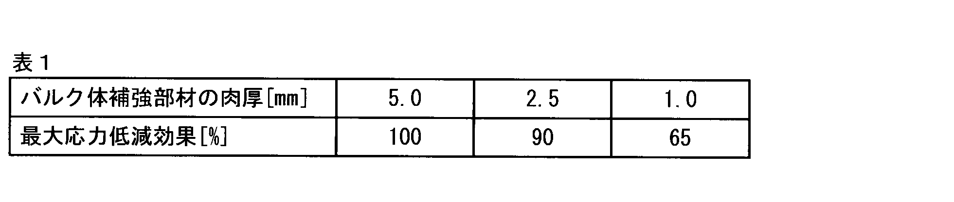
上記の実施形態では、超電導バルクマグネットは、集合体下部補強部材を有した状態で、回転機器等に磁極として取り付けられている。しかしながら、回転機器等に磁極の取り付け面として、たとえば、無酸素銅からなる冷却板が備えられている場合には、超電導バルクマグネットは集合体下部補強部材を有していなくてもよい。すなわち、集合体下部補強部材を有していない超電導バルクマグネットを、回転機器の冷却板に取り付け、一体化するように固定すれば、当該冷却板を含むことにより、上述した超電導バルクマグネットの構成が実現できる。したがって、集合体下部補強部材は、回転機器等の磁極の取り付け面等であってもよい。
本実施例の超電導バルクマグネットでは、Gd-Ba-Cu-O系酸化物超電導バルク体を用いた。まず市販されている純度99.9質量%のガドリニウム(Gd)、バリウム(Ba)、銅(Cu)のそれぞれの酸化物の粉末を、Gd:Ba:Cu=1.6:2.3:3.3のモル比で秤量し、それに白金を0.5質量%及び銀を10質量%加えた。この秤量粉を1時間かけて十分混練してから、大気中にて1173Kで8時間仮焼した。次に、金型を用いて仮焼粉を円板形状に成形した。この成形体を1423Kまで加熱して溶融状態にし、30分間保持した後、降温途中で種付けを行い、1278K~1252Kの温度領域を100時間かけて徐冷し結晶成長させ、直径70mmの単結晶状超電導バルク体を得た。この単結晶状超電導バルク体を、図5に示す形状に面取り加工を施して一辺50mm、高さ20mmの八角形状に加工し、酸素気流中において723Kで100時間熱処理した。

実施例1と同様の試験を、超電導バルク体を2個×2個の計4個組み合わせた場合について実施した。表3のケース2-A~2-Dでは、集合体側面補強部材上の、超電導バルクマグネットの平面外周8か所に加えて、内部の1箇所にボルトを通して締結した。本発明例であるケース2-Eでは、内部のボルト締めは行わなかった。表3に、外部磁場4Tの着磁条件において、ケース2-B~2-Eについて、ケース2-Aの超電導バルクマグネットの総磁束量を基準とした場合の比較を示す。

実施例3では、図3Aに示したレーストラック型の酸化物超電導バルク体を有する超電導バルクマグネットについて検証した。本実施例の酸化物超電導バルクマグネットでは、Gd(Dy)-Ba-Cu-O系酸化物超電導バルク体を用いた。まず市販されている純度99.9質量%の希土類元素(RE)、バリウム(Ba)、銅(Cu)のそれぞれの酸化物の粉末を、RE:Ba:Cu=1.6:2.3:3.3のモル比で秤量し、それにBaCeO3を1.5質量%及び銀を20質量%加えた。この秤量粉を1時間かけて十分混練してから、大気中にて1173Kで8時間仮焼した。このとき、RE組成として(Gd:Dy)=(100:0)、(95:5)、(90:10)、(85:15)の四種類の仮焼粉を作製した。これらの仮焼粉を直径200mmの金型中に同心円状にそれぞれ直径50mmの領域に(100:0)の仮焼粉を配置し、その周り直径100mmの領域に(95:5)の仮称粉を、さらにその周囲150mmの領域に(90:10)の仮焼粉を配置し、残りを(85:15)の仮焼粉を配置し加圧成形した。

実施例4では、図4に示す貫通孔が形成された酸化物超電導バルク体から構成される酸化物超電導バルクマグネットについて検証した。本実施例の酸化物超電導バルクマグネットでは、Gd(Dy)-Ba-Cu-O系酸化物超電導バルク体を用いた。まず市販されている純度99.9質量%の希土類元素(RE)、バリウム(Ba)、銅(Cu)のそれぞれの酸化物の粉末を、RE:Ba:Cu=1.8:2.4:3.6のモル比で秤量し、それにBaCeO3を1.5質量%及び銀を20質量%加えた。この秤量粉を1時間かけて十分混練してから、大気中にて1173Kで8時間仮焼した。この時、RE組成として(Gd:Dy)=(100:0)、(96:4)、(92:8)、(88:12)の四種類の仮焼粉を作製した。これらの仮焼粉を直径200mmの金型中に同心円状にそれぞれ直径50mmの領域に(100:0)の仮焼粉を配置し、その周り直径100mmの領域に(96:4)の仮称粉を、さらにその周囲150mmの領域に(92:8)の仮焼粉を配置し、残りを(88:12)の仮焼粉を配置し加圧成形した。
実施例5では、図10に示す円柱形状の酸化物超電導バルク体から構成される酸化物超電導バルクマグネットについて検証した。本実施例の酸化物超電導バルクマグネットでは、Gd-Ba-Cu-O系酸化物超電導バルク体を用いた。まず市販されている純度99.9質量%のガドリニウム(Gd)、バリウム(Ba)、銅(Cu)のそれぞれの酸化物の粉末を、Gd:Ba:Cu=1:2:3のモル比で秤量し、それにBaCeO3を1.5質量%を添加し、十分に混合した後、1183Kで5時間、酸素気流中で仮焼し、更に粉砕および混練を行った後、再び1193Kで仮焼し粉砕することでGd系123相の仮焼粉を作製した。また、同様の各酸化物原料を用い、Gd:Ba:Cu=2:1:1のモル比で秤量し、それにBaCeO3を1.5質量%を添加し、十分に混合した後、1183Kで5時間、酸素気流中で仮焼し、更に粉砕および混練を行った後、再び1198Kで仮焼し粉砕することでGd系211相の仮焼粉を作製した。
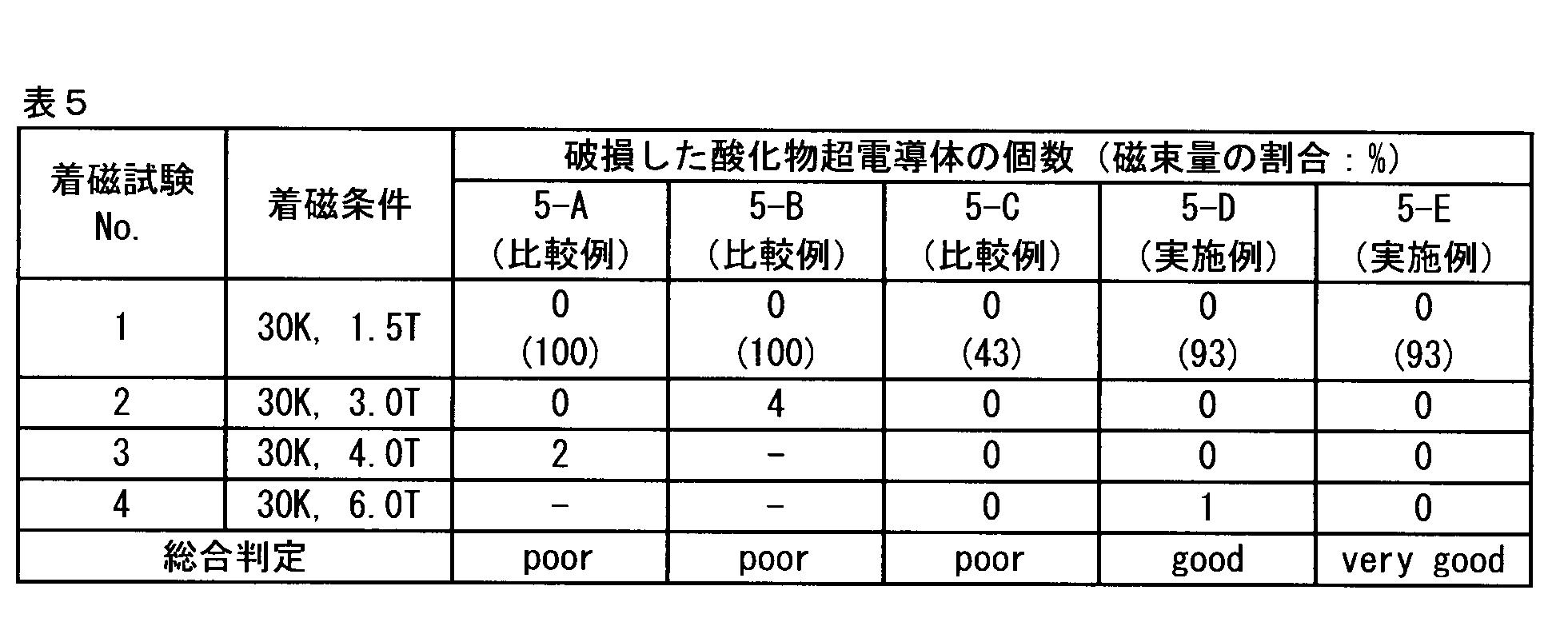
実施例6では、図9に示す六角柱形状の酸化物超電導バルク体から構成される酸化物超電導バルクマグネットについて検証した。本実施例の酸化物超電導バルクマグネットでは、Dy-Ba-Cu-O系酸化物超電導バルク体を用いた。まず市販されている純度99.9質量%の希土類元素(RE)、バリウム(Ba)、銅(Cu)のそれぞれの酸化物の粉末を、Dy:Ba:Cu=1:2:3のモル比で秤量し、それにBaCeO3を1.5質量%を添加し、十分に混合した後、1183Kで5時間、酸素気流中で仮焼し、更に粉砕および混練を行った後、再び1193Kで仮焼し粉砕することでDy系123相の仮焼粉を作製した。また、同様の各酸化物原料を用い、Dy:Ba:Cu=2:1:1のモル比で秤量し、それにBaCeO3を1.5質量%を添加し、十分に混合した後、1183Kで5時間、酸素気流中で仮焼し、更に粉砕および混練を行った後、再び1198Kで仮焼し粉砕することでDy系211相の仮焼粉を作製した。

110、210 酸化物超電導バルク体
120、210 バルク体補強部材
130、230 集合体側面補強部材
132 締結孔(貫通孔)
140、240 集合体上部補強部材
142 締結孔(貫通孔)
150、250 集合体下部補強部材
152 締結孔(貫通孔)
160、260 スペーサー
162 空間
212 貫通孔
300 回転機器
310 回転子
320 回転軸
Claims (14)
- 単結晶状のRE1Ba2Cu3Oy(REはY又は希土類元素から選ばれる1種又は2種以上の元素。6.8≦y≦7.1)中にRE2BaCuO5が分散した組織を有し、上面と下面と側面とを備える柱状の酸化物超電導バルク体を複数個組み合わせてなる酸化物超電導バルクマグネットであって、
前記酸化物超電導バルク体と、前記酸化物超電導バルク体の側面を覆うように配置されたバルク体補強部材と、からなるバルク体ユニットが、同一方向を向き、かつ互いに接するように配置されて集合体を形成し、
前記集合体の側面は、集合体側面補強部材により覆われており、
前記集合体の上面および下面は、それぞれ、集合体上部補強部材および集合体下部補強部材により覆われており、
前記集合体側面補強部材と前記集合体上部補強部材と前記集合体下部補強部材とが一体化された構成を有することを特徴とする酸化物超電導バルクマグネット。 - 前記バルク体補強部材は、肉厚が5.0mm以下であることを特徴とする請求項1に記載の酸化物超電導バルクマグネット。
- 前記集合体上部補強部材を構成する材質と、前記集合体下部補強部材を構成する材質とが異なり、前記集合体上部補強部材は前記集合体下部補強部材よりも300Kにおける降伏強度が高く、前記集合体下部補強部材は前記集合体上部補強部材よりも熱伝導率が高いことを特徴とする請求項1または2に記載の酸化物超電導バルクマグネット。
- 前記集合体上部補強部材を構成する材質が非磁性であり、かつ、300Kにおける降伏強度が200MPa以上であり、
前記集合体下部補強部材を構成する材質の熱伝導率が50W/m・K以上であることを特徴とする請求項1から3のいずれか1項に記載の酸化物超電導バルクマグネット。 - 前記集合体側面補強部材の高さは、前記集合体の高さ以上であることを特徴とする請求項1から4のいずれか1項に記載の酸化物超電導バルクマグネット。
- 前記集合体側面補強部材と、前記集合体上部補強部材または前記集合体下部補強部材と、が一体構造であることを特徴とする請求項1から5のいずれか1項に記載の酸化物超電導バルクマグネット。
- 前記集合体側面補強部材と前記集合体上部補強部材と前記集合体下部補強部材とが、固定手段により一体化されていることを特徴とする請求項1から6のいずれか1項に記載の酸化物超電導バルクマグネット。
- 前記バルク体ユニットを、同一方向を向きかつ互いに接するように配置することにより、前記集合体内部に生じた空間を通じて、前記集合体上部補強部材と前記集合体下部補強部材とが一体化されていることを特徴とする請求項7に記載の酸化物超電導バルクマグネット。
- 前記酸化物超電導バルク体には、上面および下面を貫通する貫通孔が形成されており、
前記貫通孔を通じて、前記集合体上部補強部材と前記集合体下部補強部材とが一体化されていることを特徴とする請求項7または8に記載の酸化物超電導バルクマグネット。 - 前記酸化物超電導バルク体は、平面視形状が多角形であることを特徴とする請求項1から9のいずれか1項に記載の酸化物超電導バルクマグネット。
- 前記酸化物超電導バルク体は、平面視形状が、多角形の頂点が丸み加工された形状であることを特徴とする請求項1から9のいずれか1項に記載の酸化物超電導バルクマグネット。
- 前記酸化物超電導バルク体は、前記多角形が四角形、六角形、又は、八角形であることを特徴とする請求項10または11に記載の酸化物超電導バルクマグネット。
- 前記酸化物超電導バルク体は、平面視形状が円であることを特徴とする請求項1から9のいずれか1項に記載の酸化物超電導バルクマグネット。
- 前記酸化物超電導バルク体は、平面視形状が、対向する一対の平行な直線と、対向する一対の曲線と、が接続されたレーストラック形状であることを特徴とする請求項1から9のいずれか1項に記載の酸化物超電導バルクマグネット。
Priority Applications (4)
| Application Number | Priority Date | Filing Date | Title |
|---|---|---|---|
| US15/526,541 US10283243B2 (en) | 2014-11-14 | 2015-11-13 | Oxide superconducting bulk magnet |
| JP2016559127A JP6324529B2 (ja) | 2014-11-14 | 2015-11-13 | 酸化物超電導バルクマグネット |
| EP15858130.6A EP3220397B1 (en) | 2014-11-14 | 2015-11-13 | Oxide superconducting bulk magnet |
| CN201580061567.2A CN107210111B (zh) | 2014-11-14 | 2015-11-13 | 氧化物超导块状磁铁 |
Applications Claiming Priority (4)
| Application Number | Priority Date | Filing Date | Title |
|---|---|---|---|
| JP2014231388 | 2014-11-14 | ||
| JP2014-231388 | 2014-11-14 | ||
| JP2015022384 | 2015-02-06 | ||
| JP2015-022384 | 2015-02-06 |
Publications (1)
| Publication Number | Publication Date |
|---|---|
| WO2016076433A1 true WO2016076433A1 (ja) | 2016-05-19 |
Family
ID=55954508
Family Applications (1)
| Application Number | Title | Priority Date | Filing Date |
|---|---|---|---|
| PCT/JP2015/082044 Ceased WO2016076433A1 (ja) | 2014-11-14 | 2015-11-13 | 酸化物超電導バルクマグネット |
Country Status (5)
| Country | Link |
|---|---|
| US (1) | US10283243B2 (ja) |
| EP (1) | EP3220397B1 (ja) |
| JP (1) | JP6324529B2 (ja) |
| CN (1) | CN107210111B (ja) |
| WO (1) | WO2016076433A1 (ja) |
Cited By (2)
| Publication number | Priority date | Publication date | Assignee | Title |
|---|---|---|---|---|
| JP2019091803A (ja) * | 2017-11-15 | 2019-06-13 | 株式会社日立製作所 | 超伝導磁石装置 |
| JP2019161738A (ja) * | 2018-03-08 | 2019-09-19 | 三菱重工業株式会社 | 超電導回転機械用かご型ロータ、超電導回転機械用ステータ、及び超電導回転機械 |
Families Citing this family (4)
| Publication number | Priority date | Publication date | Assignee | Title |
|---|---|---|---|---|
| DE102018216890A1 (de) * | 2018-10-02 | 2020-04-02 | Rolls-Royce Deutschland Ltd & Co Kg | Rotor und Maschine mit supraleitendem Permanentmagneten |
| US11393780B2 (en) | 2019-07-26 | 2022-07-19 | Sandisk Technologies Llc | Bonded assembly containing oxidation barriers, hybrid bonding, or air gap, and methods of forming the same |
| US11515273B2 (en) | 2019-07-26 | 2022-11-29 | Sandisk Technologies Llc | Bonded assembly containing oxidation barriers, hybrid bonding, or air gap, and methods of forming the same |
| US11139272B2 (en) | 2019-07-26 | 2021-10-05 | Sandisk Technologies Llc | Bonded assembly containing oxidation barriers and/or adhesion enhancers and methods of forming the same |
Citations (6)
| Publication number | Priority date | Publication date | Assignee | Title |
|---|---|---|---|---|
| JPH09213523A (ja) * | 1996-02-01 | 1997-08-15 | Murata Mfg Co Ltd | 非可逆回路素子 |
| JPH11284238A (ja) * | 1998-03-27 | 1999-10-15 | Imura Zairyo Kaihatsu Kenkyusho:Kk | 超電導磁場発生素子 |
| JP2000277333A (ja) * | 1999-03-26 | 2000-10-06 | Aisin Seiki Co Ltd | 超電導体の着磁方法及び超電導磁石装置 |
| JP2001046351A (ja) * | 1999-08-12 | 2001-02-20 | Sumitomo Special Metals Co Ltd | 磁界発生装置およびその組立方法 |
| WO2004097865A1 (ja) * | 2003-04-25 | 2004-11-11 | Japan Science And Technology Agency | 超電導永久磁石装置 |
| WO2011071071A1 (ja) * | 2009-12-08 | 2011-06-16 | 新日本製鐵株式会社 | 酸化物超伝導バルク磁石部材 |
Family Cites Families (7)
| Publication number | Priority date | Publication date | Assignee | Title |
|---|---|---|---|---|
| JPH07182934A (ja) | 1993-12-24 | 1995-07-21 | Hitachi Ltd | バルク状高温超電導導体 |
| JP4012311B2 (ja) | 1998-05-26 | 2007-11-21 | 新日本製鐵株式会社 | バルク超電導部材とマグネットおよびそれらの製造方法 |
| DE19835454A1 (de) * | 1998-08-05 | 2000-02-10 | Aventis Res & Tech Gmbh & Co | Geschütztes supraleitendes Bauteil und Verfahren zu dessen Herstellung |
| JP2001307916A (ja) | 2000-04-24 | 2001-11-02 | Toshiba Corp | 超電導磁石装置 |
| CN2817310Y (zh) * | 2005-08-15 | 2006-09-13 | 广达电脑股份有限公司 | 具有补强构件的电子装置 |
| JP6422631B2 (ja) | 2013-01-30 | 2018-11-14 | 新日鐵住金株式会社 | 超電導バルク磁石 |
| US9324486B2 (en) * | 2013-06-17 | 2016-04-26 | Massachusetts Institute Of Technology | Partial insulation superconducting magnet |
-
2015
- 2015-11-13 JP JP2016559127A patent/JP6324529B2/ja active Active
- 2015-11-13 EP EP15858130.6A patent/EP3220397B1/en active Active
- 2015-11-13 CN CN201580061567.2A patent/CN107210111B/zh active Active
- 2015-11-13 WO PCT/JP2015/082044 patent/WO2016076433A1/ja not_active Ceased
- 2015-11-13 US US15/526,541 patent/US10283243B2/en active Active
Patent Citations (6)
| Publication number | Priority date | Publication date | Assignee | Title |
|---|---|---|---|---|
| JPH09213523A (ja) * | 1996-02-01 | 1997-08-15 | Murata Mfg Co Ltd | 非可逆回路素子 |
| JPH11284238A (ja) * | 1998-03-27 | 1999-10-15 | Imura Zairyo Kaihatsu Kenkyusho:Kk | 超電導磁場発生素子 |
| JP2000277333A (ja) * | 1999-03-26 | 2000-10-06 | Aisin Seiki Co Ltd | 超電導体の着磁方法及び超電導磁石装置 |
| JP2001046351A (ja) * | 1999-08-12 | 2001-02-20 | Sumitomo Special Metals Co Ltd | 磁界発生装置およびその組立方法 |
| WO2004097865A1 (ja) * | 2003-04-25 | 2004-11-11 | Japan Science And Technology Agency | 超電導永久磁石装置 |
| WO2011071071A1 (ja) * | 2009-12-08 | 2011-06-16 | 新日本製鐵株式会社 | 酸化物超伝導バルク磁石部材 |
Non-Patent Citations (1)
| Title |
|---|
| See also references of EP3220397A4 * |
Cited By (2)
| Publication number | Priority date | Publication date | Assignee | Title |
|---|---|---|---|---|
| JP2019091803A (ja) * | 2017-11-15 | 2019-06-13 | 株式会社日立製作所 | 超伝導磁石装置 |
| JP2019161738A (ja) * | 2018-03-08 | 2019-09-19 | 三菱重工業株式会社 | 超電導回転機械用かご型ロータ、超電導回転機械用ステータ、及び超電導回転機械 |
Also Published As
| Publication number | Publication date |
|---|---|
| JP6324529B2 (ja) | 2018-05-23 |
| EP3220397A4 (en) | 2018-06-27 |
| US10283243B2 (en) | 2019-05-07 |
| CN107210111A (zh) | 2017-09-26 |
| CN107210111B (zh) | 2019-10-01 |
| JPWO2016076433A1 (ja) | 2017-08-31 |
| US20170316859A1 (en) | 2017-11-02 |
| EP3220397A1 (en) | 2017-09-20 |
| EP3220397B1 (en) | 2022-04-27 |
Similar Documents
| Publication | Publication Date | Title |
|---|---|---|
| JP6324529B2 (ja) | 酸化物超電導バルクマグネット | |
| EP2511917B1 (en) | Oxide superconducting bulk magnet member | |
| EP2251962A2 (en) | Cooling mechanism for axial gap type rotating machines | |
| CN107112108B (zh) | 氧化物超导块状磁铁 | |
| WO2014189043A1 (ja) | 酸化物超電導バルクマグネット | |
| JP4719308B1 (ja) | 酸化物超伝導バルク磁石部材 | |
| JP5195961B2 (ja) | 酸化物超伝導バルク磁石部材 | |
| JP5736216B2 (ja) | 超伝導バルク体とその製造方法および超伝導バルク磁石 | |
| JP4653555B2 (ja) | 酸化物超伝導磁石材料及び酸化物超伝導磁石システム | |
| JP4903729B2 (ja) | 酸化物超伝導マグネット及びその製造方法、並びに冷却方法 | |
| JP4799979B2 (ja) | 酸化物超伝導体コイル、酸化物超伝導体コイルの製造方法、酸化物超伝導体コイルの励磁方法、酸化物超伝導体コイルの冷却方法、及びマグネットシステム | |
| US10748691B2 (en) | Oxide superconducting bulk magnet | |
| EP3115998A1 (en) | Oxide superconductive bulk magnet | |
| JP2021110384A (ja) | 超電導軸受 | |
| JP2020164340A (ja) | 酸化物超電導バルク導体、及び、その製造方法 | |
| EP0734081A1 (en) | Oxide superconducting wire and manufacturing method | |
| JPH07277730A (ja) | 高ダンピング酸化物超伝導材料およびその製造方法 |
Legal Events
| Date | Code | Title | Description |
|---|---|---|---|
| 121 | Ep: the epo has been informed by wipo that ep was designated in this application |
Ref document number: 15858130 Country of ref document: EP Kind code of ref document: A1 |
|
| DPE1 | Request for preliminary examination filed after expiration of 19th month from priority date (pct application filed from 20040101) | ||
| ENP | Entry into the national phase |
Ref document number: 2016559127 Country of ref document: JP Kind code of ref document: A |
|
| REEP | Request for entry into the european phase |
Ref document number: 2015858130 Country of ref document: EP |
|
| WWE | Wipo information: entry into national phase |
Ref document number: 15526541 Country of ref document: US |
|
| NENP | Non-entry into the national phase |
Ref country code: DE |