WO2016079945A1 - レーダ衛星およびこれを用いたレーダ衛星システム - Google Patents
レーダ衛星およびこれを用いたレーダ衛星システム Download PDFInfo
- Publication number
- WO2016079945A1 WO2016079945A1 PCT/JP2015/005584 JP2015005584W WO2016079945A1 WO 2016079945 A1 WO2016079945 A1 WO 2016079945A1 JP 2015005584 W JP2015005584 W JP 2015005584W WO 2016079945 A1 WO2016079945 A1 WO 2016079945A1
- Authority
- WO
- WIPO (PCT)
- Prior art keywords
- radar
- unit
- satellite
- panel
- communication
- Prior art date
- Legal status (The legal status is an assumption and is not a legal conclusion. Google has not performed a legal analysis and makes no representation as to the accuracy of the status listed.)
- Ceased
Links
Images

Classifications
-
- B—PERFORMING OPERATIONS; TRANSPORTING
- B64—AIRCRAFT; AVIATION; COSMONAUTICS
- B64G—COSMONAUTICS; VEHICLES OR EQUIPMENT THEREFOR
- B64G1/00—Cosmonautic vehicles
- B64G1/22—Parts of, or equipment specially adapted for fitting in or to, cosmonautic vehicles
- B64G1/24—Guiding or controlling apparatus, e.g. for attitude control
- B64G1/26—Guiding or controlling apparatus, e.g. for attitude control using jets
-
- B—PERFORMING OPERATIONS; TRANSPORTING
- B64—AIRCRAFT; AVIATION; COSMONAUTICS
- B64G—COSMONAUTICS; VEHICLES OR EQUIPMENT THEREFOR
- B64G1/00—Cosmonautic vehicles
- B64G1/10—Artificial satellites; Systems of such satellites; Interplanetary vehicles
- B64G1/1014—Navigation satellites
-
- B—PERFORMING OPERATIONS; TRANSPORTING
- B64—AIRCRAFT; AVIATION; COSMONAUTICS
- B64G—COSMONAUTICS; VEHICLES OR EQUIPMENT THEREFOR
- B64G1/00—Cosmonautic vehicles
- B64G1/10—Artificial satellites; Systems of such satellites; Interplanetary vehicles
- B64G1/1021—Earth observation satellites
- B64G1/1035—Earth observation satellites using radar for mapping, surveying or detection, e.g. of intelligence
-
- B—PERFORMING OPERATIONS; TRANSPORTING
- B64—AIRCRAFT; AVIATION; COSMONAUTICS
- B64G—COSMONAUTICS; VEHICLES OR EQUIPMENT THEREFOR
- B64G1/00—Cosmonautic vehicles
- B64G1/22—Parts of, or equipment specially adapted for fitting in or to, cosmonautic vehicles
- B64G1/222—Parts of, or equipment specially adapted for fitting in or to, cosmonautic vehicles for deploying structures between a stowed and deployed state
- B64G1/2221—Parts of, or equipment specially adapted for fitting in or to, cosmonautic vehicles for deploying structures between a stowed and deployed state characterised by the manner of deployment
- B64G1/2222—Folding
-
- B—PERFORMING OPERATIONS; TRANSPORTING
- B64—AIRCRAFT; AVIATION; COSMONAUTICS
- B64G—COSMONAUTICS; VEHICLES OR EQUIPMENT THEREFOR
- B64G1/00—Cosmonautic vehicles
- B64G1/22—Parts of, or equipment specially adapted for fitting in or to, cosmonautic vehicles
- B64G1/24—Guiding or controlling apparatus, e.g. for attitude control
- B64G1/242—Orbits and trajectories
-
- B—PERFORMING OPERATIONS; TRANSPORTING
- B64—AIRCRAFT; AVIATION; COSMONAUTICS
- B64G—COSMONAUTICS; VEHICLES OR EQUIPMENT THEREFOR
- B64G1/00—Cosmonautic vehicles
- B64G1/22—Parts of, or equipment specially adapted for fitting in or to, cosmonautic vehicles
- B64G1/42—Arrangements or adaptations of power supply systems
- B64G1/44—Arrangements or adaptations of power supply systems using radiation, e.g. deployable solar arrays
- B64G1/443—Photovoltaic cell arrays
-
- G—PHYSICS
- G01—MEASURING; TESTING
- G01S—RADIO DIRECTION-FINDING; RADIO NAVIGATION; DETERMINING DISTANCE OR VELOCITY BY USE OF RADIO WAVES; LOCATING OR PRESENCE-DETECTING BY USE OF THE REFLECTION OR RERADIATION OF RADIO WAVES; ANALOGOUS ARRANGEMENTS USING OTHER WAVES
- G01S13/00—Systems using the reflection or reradiation of radio waves, e.g. radar systems; Analogous systems using reflection or reradiation of waves whose nature or wavelength is irrelevant or unspecified
- G01S13/88—Radar or analogous systems specially adapted for specific applications
- G01S13/89—Radar or analogous systems specially adapted for specific applications for mapping or imaging
-
- G—PHYSICS
- G01—MEASURING; TESTING
- G01S—RADIO DIRECTION-FINDING; RADIO NAVIGATION; DETERMINING DISTANCE OR VELOCITY BY USE OF RADIO WAVES; LOCATING OR PRESENCE-DETECTING BY USE OF THE REFLECTION OR RERADIATION OF RADIO WAVES; ANALOGOUS ARRANGEMENTS USING OTHER WAVES
- G01S7/00—Details of systems according to groups G01S13/00, G01S15/00, G01S17/00
- G01S7/003—Transmission of data between radar, sonar or lidar systems and remote stations
-
- G—PHYSICS
- G01—MEASURING; TESTING
- G01S—RADIO DIRECTION-FINDING; RADIO NAVIGATION; DETERMINING DISTANCE OR VELOCITY BY USE OF RADIO WAVES; LOCATING OR PRESENCE-DETECTING BY USE OF THE REFLECTION OR RERADIATION OF RADIO WAVES; ANALOGOUS ARRANGEMENTS USING OTHER WAVES
- G01S7/00—Details of systems according to groups G01S13/00, G01S15/00, G01S17/00
- G01S7/02—Details of systems according to groups G01S13/00, G01S15/00, G01S17/00 of systems according to group G01S13/00
-
- G—PHYSICS
- G01—MEASURING; TESTING
- G01S—RADIO DIRECTION-FINDING; RADIO NAVIGATION; DETERMINING DISTANCE OR VELOCITY BY USE OF RADIO WAVES; LOCATING OR PRESENCE-DETECTING BY USE OF THE REFLECTION OR RERADIATION OF RADIO WAVES; ANALOGOUS ARRANGEMENTS USING OTHER WAVES
- G01S7/00—Details of systems according to groups G01S13/00, G01S15/00, G01S17/00
- G01S7/02—Details of systems according to groups G01S13/00, G01S15/00, G01S17/00 of systems according to group G01S13/00
- G01S7/03—Details of HF subsystems specially adapted therefor, e.g. common to transmitter and receiver
-
- G—PHYSICS
- G01—MEASURING; TESTING
- G01S—RADIO DIRECTION-FINDING; RADIO NAVIGATION; DETERMINING DISTANCE OR VELOCITY BY USE OF RADIO WAVES; LOCATING OR PRESENCE-DETECTING BY USE OF THE REFLECTION OR RERADIATION OF RADIO WAVES; ANALOGOUS ARRANGEMENTS USING OTHER WAVES
- G01S7/00—Details of systems according to groups G01S13/00, G01S15/00, G01S17/00
- G01S7/02—Details of systems according to groups G01S13/00, G01S15/00, G01S17/00 of systems according to group G01S13/00
- G01S7/28—Details of pulse systems
-
- B—PERFORMING OPERATIONS; TRANSPORTING
- B64—AIRCRAFT; AVIATION; COSMONAUTICS
- B64G—COSMONAUTICS; VEHICLES OR EQUIPMENT THEREFOR
- B64G1/00—Cosmonautic vehicles
- B64G1/22—Parts of, or equipment specially adapted for fitting in or to, cosmonautic vehicles
- B64G1/64—Systems for coupling or separating cosmonautic vehicles or parts thereof, e.g. docking arrangements
- B64G1/648—Tethers
-
- G—PHYSICS
- G01—MEASURING; TESTING
- G01S—RADIO DIRECTION-FINDING; RADIO NAVIGATION; DETERMINING DISTANCE OR VELOCITY BY USE OF RADIO WAVES; LOCATING OR PRESENCE-DETECTING BY USE OF THE REFLECTION OR RERADIATION OF RADIO WAVES; ANALOGOUS ARRANGEMENTS USING OTHER WAVES
- G01S13/00—Systems using the reflection or reradiation of radio waves, e.g. radar systems; Analogous systems using reflection or reradiation of waves whose nature or wavelength is irrelevant or unspecified
- G01S13/88—Radar or analogous systems specially adapted for specific applications
- G01S13/89—Radar or analogous systems specially adapted for specific applications for mapping or imaging
- G01S13/90—Radar or analogous systems specially adapted for specific applications for mapping or imaging using synthetic aperture techniques, e.g. synthetic aperture radar [SAR] techniques
Definitions
- the present invention relates to a radar satellite that observes the surface of the earth from outer space, and a radar satellite system using the same.
- a radar satellite acquires image information (radar image) as observation information by transmitting and receiving radar waves such as microwaves and millimeter waves to and from the earth surface. Therefore, it is possible to acquire image information even in situations where it is difficult to shoot with an optical satellite (situations such as nighttime and cloudy sky).
- a synthetic aperture radar is known as a radar device provided in a radar satellite.
- Synthetic aperture radar performs transmission and reception of radar waves many times toward the surface of the earth while the satellite is orbiting and synthesizes the received radar waves.
- an apparently large antenna is realized by the movement of the satellite, so that it is possible to acquire image information with excellent resolution.
- Patent Literature 1 discloses a remote detection satellite or a long-distance communication satellite using an interference synthetic aperture radar.
- moving objects cannot be detected with the same resolution as when detecting the surface of the earth (observation objects that are stationary such as terrain), so moving objects cannot be used as observation objects.
- the terrain or marine conditions, weather, or environment of a certain area on the earth's surface is an observation target, such an observation target area is an observation target that does not substantially move, so a large number of received waves are synthesized. This can increase the resolution.
- an object that moves on or above the earth's surface such as a ship or an aircraft, moves while receiving a large number of received waves, so the resolution cannot be increased by synthesis. Therefore, it is difficult for a synthetic aperture radar to detect a moving object with sufficient resolution.
- the present invention has been made to solve such problems, and it is possible to acquire more detailed information including moving objects when acquiring observation information from the earth surface from outer space. It is an object to provide a simple radar satellite and a radar satellite system using the same.
- a radar satellite includes a radar unit configured by connecting a plurality of radar panels including a plurality of antennas and solar cells that transmit and receive radar waves into a single flat plate, A communication unit that communicates with the ground or spacecraft, wherein the radar unit is a radar panel array that is a plate-like structure constituted by a plurality of the radar panels, and a side frame that supports the radar panel. And a deployable truss structure configured to be foldable and unfoldable.
- a flat, large radar unit is configured by supporting a radar panel array including a plurality of radar panels by a deployable truss structure that can be folded and deployed. Therefore, a large conformal array radar can be constructed in outer space by folding the radar panel array during launch and deploying the radar panel array in outer space. As a result, for example, a relatively small moving object can be an object to be observed. Therefore, an object that moves not only from outer space but also in the area including the sky (sky sea area) as well as the earth surface (the ground surface and the sea surface). It is possible to provide a radar satellite capable of acquiring more detailed observation information including.
- the size of the radar unit can be adjusted by adjusting the number of radar panels constituting the radar panel array.
- the radar part of the radar satellite is composed of a plurality of radar panels, and each radar panel has a plurality of antennas. Therefore, even if some antennas fail, the influence on the radar performance is suppressed or avoided. Can do. Further, since the radar unit is composed of a large number of radar panels, even if some of the radar panels break down, they can be replaced with supplies. Therefore, the redundancy of the radar satellite can be improved.
- the radar unit is connected by a bendable node at one side of the plurality of radar panels supported by the side frame, and the radar panels are bent at the node so as to be in close contact with each other.
- the radar panel unit folded so as to be deployed is a plurality of connected configurations, or the plurality of side frames constituting the deployed deployed truss structure are respectively connected to the radar.
- the structure to which the panel was attached may be sufficient.
- the radar satellite having the above-described configuration may include a thruster unit that performs trajectory correction and attitude control of the radar unit, and a radar control unit that performs operation control of the thruster unit and the radar unit.
- the radar satellite having the above-described configuration may include a bus unit that is a counterweight of the radar unit, and a tether wire that connects the radar unit and the bus unit.
- the radar panel includes a charger that charges the power generated by the solar battery, and a power controller that controls at least charging / discharging of the charger. May be.
- the radar satellite having the above-described configuration may include a service unit that connects the deployed radar panel units to construct the radar unit and maintains the constructed radar unit.
- the present invention includes a radar satellite having the above-described configuration, a ground communication device that communicates with the radar satellite, and a ground management device that manages the radar satellite via the ground communication device.
- a radar satellite system is also included.
- the radar satellite system having the above configuration may further include at least one of an aircraft, a ship, and a vehicle that can communicate with the radar satellite or the ground management device.
- a radar satellite capable of acquiring more detailed information including moving objects and a radar satellite system using the same Can be provided.
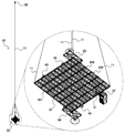
- FIG. 1 is a schematic perspective view showing a basic configuration example of a radar satellite according to Embodiment 1 of the present invention.
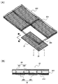
- 2A is a schematic perspective view showing a configuration example of a main part of the radar unit of the radar satellite shown in FIG. 1
- FIG. 2B is a view taken along line II in FIG. 2A. It is a fragmentary sectional view.
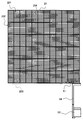
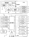
- FIG. 2 is a schematic plan view illustrating a configuration example of a radar panel array and a radar panel unit of the radar unit illustrated in FIG. 1. It is a typical block diagram which shows an example of the control structure of the radar satellite shown in FIG. It is a typical block diagram which shows the structural example of the radar panel of the radar satellite shown in FIG. FIG.
- FIG. 6 is a schematic block diagram illustrating a configuration example of a radar cell included in the radar panel illustrated in FIG. 5.
- FIG. 5 is a schematic block diagram illustrating a configuration example of a radar thruster unit of the radar satellite illustrated in FIG. 4. It is a schematic diagram which shows an example of the observation of the earth surface using the radar satellite shown to FIG. 1 and FIG. It is a schematic diagram which shows the structural example of the radar satellite system which concerns on Embodiment 2 of this invention. It is a typical block diagram which shows the other structural example of the radar satellite system which concerns on Embodiment 2 of this invention.
- the radar satellite 10 includes a radar unit 20, a bus unit 30, a tether wire 11, and the like.
- the radar unit 20 includes a radar panel array 201 and a deployed truss structure 202.
- the radar panel array 201 is a single plate-like structure composed of a plurality of radar panels 21 and is supported by a deployed truss structure 202.
- the deployment truss structure 202 is a structure in which the side frames 204 that support the radar panel 21 are connected so as to be foldable and unfoldable. It is made of a pipe material (such as CFRP) and a hinge member (connection member).
- the radar unit 20 is also provided with a radar thruster unit 40, a communication / control unit 50, a service unit 51, a replenisher 52, and the like.
- the radar panel 21 is provided with a plurality of radar cells 22.
- the radar cell 22 includes an antenna unit 26, a solar cell 241, a battery 242, and the like as shown in FIG. 2B (a partial cross-sectional view taken along the line II in FIG. 2A).
- the antenna unit 26 includes a patch antenna 260, a transmission / reception unit 261, and the like.
- the patch antenna 260 is provided on the back surface of the panel substrate 211 (the lower surface in FIG. 2B).
- the solar cell 241 is provided on the surface of the panel substrate 211 (the upper surface in FIG. 2B).
- the battery 242 and the transmission / reception unit 261 are provided between the solar cell 241 and the panel substrate 211, and the battery 242, the transmission / reception unit 261 and the patch antenna 260 are electrically connected by the panel wiring 212 provided on the back surface side.
- the solar cell 241 is also connected to the battery 242 and the like by wiring not shown in FIG.
- the patch antenna 260 is an antenna of the radar unit 20 that transmits and receives radar waves, and its specific configuration is not particularly limited, and may be a known configuration using a microstrip line. As the antenna of the radar unit 20, a known antenna other than the patch antenna 260 can also be used.
- the solar cell 241 supplies power to the radar unit 20, the radar thruster unit 40, the communication / control unit 50, and the like.
- the battery 242 is a charger that charges the electric power generated by the solar cell 241, and charging / discharging is controlled by a power supply controller (not shown) in FIG. Therefore, the radar power supply unit 24 is configured by the solar cell 241, the battery 242, and the power supply controller.
- the specific structure of the solar cell 241 and the battery 242, and a power supply controller is not specifically limited, The thing of a well-known structure can be used suitably. Details of the radar cell 22 including the antenna unit 26 and the radar power supply unit 24 will be described later.
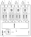
- the radar panel array 201 is composed of a plurality of (72 in the present embodiment) radar panels 21, but as shown in FIG. Are connected to each other.
- Each radar panel 21 is supported by a side frame 204.
- the radar panel unit 203 has a configuration in which two radar panels 21 are connected in the vertical direction, but is not limited thereto. That is, the radar panel unit 203 connects one side of a plurality of radar panels 21 supported by the side frame 204 at a bendable node, and bends the radar panel 21 at this node so as to be in close contact with each other. It is possible to be configured so that it can be expanded from a folded state. Therefore, the radar panel unit 203 may be composed of three or more radar panels 21 or may be connected in the horizontal direction instead of the vertical direction.
- the radar panel unit 203 is accommodated in a folded state in the panel container 53 shown in FIG. 3 before deployment.
- the radar panel unit 203 sent out from the panel container 53 is developed by the deployment device 54 shown in FIG. 3, and is connected to the other radar panel unit 203 by the service unit 51 shown in FIGS.
- a plate-like structure (radar panel array 201) in which a plurality of radar panels 21 are connected is constructed.
- the deployed and connected radar panel array 201 is constituted by a deployed truss structure 202 in which a plurality of side frames 204 are coupled. Will be supported.
- the service unit 51 not only constructs the radar panel array 201, that is, the radar unit 20, but also maintains the constructed radar unit 20.
- the radar satellite 10 when the radar satellite 10 is launched, the plurality of radar panel units 203 are folded and accommodated in the panel container 53. After being transported to outer space, the radar panel unit 203 is sent out from the panel container 53 and deployed by the deployment device 54, and the radar panel unit 203 is connected by the service unit 51. Note that the number of radar panel units 203 that can be accommodated in one panel container 53 is limited. Therefore, if a plurality of panel containers 53 are connected to form a container set, a large number of radar panel units 203 can be transported to outer space. As a result, a large conformal array radar (radar unit 20) can be constructed in outer space.
- the radar panel array 201 is composed of 72 radar panels 21 as shown in FIG. 42m x 36m) can be constructed in outer space.
- the opening area is about 1,600 m 2 , so that the radar reflection cross section (RCS) can be greatly increased.
- RCS radar reflection cross section
- the radar unit 20 is not limited to a configuration in which a plurality of radar panel units 203 including side frames are connected as described above.
- a configuration in which the radar panel 21 is attached to each of the plurality of side frame bodies 204 constituting the deployed truss structure 202 is also possible.
- each radar panel 21 may be attached to each side frame 204 by the service unit 51 shown in FIG. 1 or FIG.
- the radar unit 20 can fold and unfold a plurality of radar panel arrays 201 that are plate-like structures composed of a plurality of radar panels 21 and a plurality of side frame bodies 204 that support the radar panels 21. What is necessary is just the structure provided with the expansion
- Specific configurations of the service unit 51, the panel container 53, and the deployment device 54 are not particularly limited.
- the service unit 51 and the panel container 53 are (1) Japanese Patent Laid-Open Publication No.
- the configurations disclosed in Japanese Patent No. 184812 and (2) Japanese Published Patent Publication No. 2014-184813 can be employed.
- the configuration disclosed in (3) Japanese Published Patent Publication / JP2012-131458 can be adopted as the deployment device 54. .
- the bus unit 30 is connected to the radar unit 20 by a tether wire 11.
- the tether wire 11 extends from the mounting portion of the radar unit 20 toward the bus unit 30.
- tether wires 11 extending from the attachment portion are combined and connected to the bus portion 30.
- stretched from an attachment part may be one wire, and may be comprised with two or more wires.
- the specific configuration of the tether wire 11 is not particularly limited, and a known wire material such as a stainless steel wire formed by a plurality of thin wires or a thin tape-like wire can be suitably used.
- the bus unit 30 functions as a counterweight of the radar unit 20, and the panel container 53 can be used as the bus unit 30 as described in the published patent publications of (1) and (2) above.
- a plurality of radar thrusters 40 are provided around the radar unit 20 and perform trajectory correction and attitude control of the radar unit 20.
- two radar thruster units 40 are provided on each of two lateral sides of the four sides of the rectangular radar unit 20. In the state shown in FIG. 1, one radar thruster unit 40 on the front side in the drawing is hidden by the replenisher 52. Specific configurations of the bus unit 30 and the radar thruster unit 40 will be described later.
- the communication / control unit 50 can communicate with each of the radar unit 20, the bus unit 30, the radar thruster unit 40, and the service unit 51 constituting the radar satellite 10, and is external to the radar satellite 10, that is, on the ground or others. It is configured to be able to communicate with other spacecraft.
- the communication / control unit 50 controls the operation of the radar unit 20, the bus unit 30, the radar thruster unit 40, and the service unit 51.
- the specific configuration of the communication / control unit 50 is not particularly limited, and examples thereof include known control devices and communication devices that can be used in the field of spacecraft. Operation control and communication by the communication / control unit 50 will be described later.
- the replenisher 52 supplies chemical fuel to the radar thruster unit 40.
- the radar thruster unit 40 operates by consuming this chemical fuel, and performs trajectory correction or attitude control of the radar unit 20.
- the specific configuration of the replenishing machine 52 is not particularly limited, and a configuration known in the field of spacecraft can be suitably used.
- the radar unit 20 includes a plurality of radar panels 21, and each radar panel 21 includes a plurality of radar cells 22.
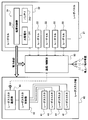
- each radar cell 22 includes a radar communication device 23, a radar power supply unit 24, a signal processor 25, an antenna unit 26, and the like.
- the radar communicator 23 communicates with the communication / control unit 50 and is connected to the signal processor 25.
- a plurality of antenna units 26 are connected to the signal processor 25.
- the antenna unit 26 includes the patch antenna 260 and the transmission / reception unit 261.
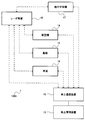
- the transmission / reception unit 261 includes a transmission amplifier 262, a reception amplifier 263, a transmission / reception switch 264, and the like as shown in FIG. It is configured.
- the transmission amplifier 262 and the reception amplifier 263 are connected in parallel to the signal processor 25 and the transmission / reception switch 264.
- the transmission / reception switch 264 is connected to the patch antenna 260 in addition to the transmission amplifier 262 and the reception amplifier 263. .
- the patch antenna 260 transmits a radar wave (transmitted wave) toward the ground surface and receives a radar wave (received wave) reflected from the ground surface.
- the signal processor 25 generates a transmission wave based on a transmission wave generation command input from the communication / control unit 50 via the radar communication device 23, and converts the reception wave into image generation information to convert the radar communication device. 23.
- the image generation information is output to the communication / control unit 50 via the radar communicator 23 and transmitted to the ground or another spacecraft.
- the transmission amplifier 262 amplifies the transmission wave generated by the signal processor 25 and sends it to the patch antenna 260 via the transmission / reception switch 264.
- the reception amplifier 263 amplifies the reception wave received by the patch antenna 260 and sends it to the signal processor 25.
- the transmission / reception switch 264 switches between transmission and reception of radar waves.
- Specific configurations of the signal processor 25 and the transmission / reception unit 261 are not particularly limited, and configurations known in the field of radar devices can be suitably used.
- the radar communicator 23 is not particularly limited as long as it can communicate with the communication / control unit 50 in outer space, and a known communication device that can be used in the spacecraft field is preferably used. Can do.
- the electromagnetic wave used for communication is not particularly limited, and may be a known radio wave or optical communication using laser light or the like.
- the configuration of the radar unit 20 described above is the same as the configuration of a general radar device, but the specific configuration of the radar unit 20 is not limited to this, and is a configuration of another known radar device. Can also be suitably used.
- the radar cell 22 includes a radar power supply unit 24 (see FIG. 2B).
- the radar power supply unit 24 includes the solar cell 241, the battery 242, and the power supply controller 243, and supplies power to the radar communication device 23, the signal processor 25, the antenna unit 26, and the like (see FIG. As will be described later, the radar thruster unit 40 and the communication / control unit 50 are also supplied with power.
- the bus unit 30 includes a bus thruster 31, a bus thruster controller 32, a bus communicator 33, a bus power supply unit 34, and the like.
- the bus thruster 31 performs trajectory correction or attitude control of the bus unit 30, and a well-known thruster for a spacecraft can be suitably used.
- the bus thruster controller 32 controls the operation of the bus thruster 31.
- the bus communicator 33 is connected to the bus thruster controller 32 and enables communication with the communication / control unit 50.
- Specific configurations of the bus thruster controller 32 and the bus communication device 33 are not particularly limited, and a known control device or communication device that can be used in the field of spacecraft can be suitably used.
- the bus power supply unit 34 supplies power to the bus thruster controller 32, the bus communicator 33, and the like (see the block arrow in FIG. 4), and includes a solar cell 341, a battery 342, a power controller 343, and the like. ing.
- the basic configuration is the same as that of the radar power supply unit 24 provided in the radar cell 22, and a specific description thereof will be omitted.
- the radar thruster section 40 includes a radar thruster 41, a radar thruster controller 42, a radar thruster communicator 43, and the like.
- the radar thruster 41 performs trajectory correction or attitude control of the radar unit 20 by the operation control of the radar thruster controller 42.
- the specific configuration of the radar thruster 41 is not particularly limited, and a well-known thruster for a spacecraft can be suitably used similarly to the bus thruster 31.
- the radar thruster controller 42 controls the operation of the radar thruster 41.
- the radar thruster communicator 43 is connected to the radar thruster controller 42 and enables communication with the communication / control unit 50.
- Specific configurations of the radar thruster controller 42 and the radar thruster communicator 43 are not particularly limited, and known control devices or communication devices that can be used in the field of spacecrafts can be suitably used.
- an operation control command from the communication / control unit 50 is input to the radar thruster controller 42 via the radar thruster communicator 43, the radar thruster 41 is operated based on the operation control command.
- the radar panel 21 constituting the radar unit 20 includes the radar power supply unit 24. As shown by the block arrows in FIG. In addition, power is supplied to the radar thruster unit 40 and the communication / control unit 50.
- the power supply path is not particularly limited, and the solar battery 241 or the battery 242 as the charger of the radar power supply unit 24 and the radar thruster unit 40 or the communication / control unit 50 may be electrically connected by a known method.
- the communication / control unit 50 is configured to be able to communicate with the radar unit 20, the bus unit 30, the radar thruster unit 40, the service unit 51, and the like, and controls the operation thereof.
- the communication / control unit 50 is configured to be communicable with the ground or another spacecraft, and the radar unit 20, the bus unit 30, the radar thruster unit 40, the service unit 51, and the like by control from the ground.
- the operations of the radar unit 20, the bus unit 30, the radar thruster unit 40, the service unit 51, and the like can be controlled by a computer program or the like stored in advance in a storage unit (not shown).
- the radar satellite 10 may have a configuration other than the radar unit 20, the bus unit 30, the radar thruster unit 40, and the service unit 51, and the communication / control unit 50 operates in other configurations. Can be controlled.
- the radar satellite 10 includes the replenisher 52, but the communication / control unit 50 may be configured to control the operation of the replenisher 52. Further, the communication / control unit 50 may be configured to control the operation of another spacecraft capable of communication.
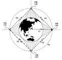
- the radar satellite 10 Observation of the surface of the earth and the sky above it (acquisition of information from the sea area) by the radar satellite 10 having the above-described configuration will be described with reference to FIG. As shown by a one-dot chain line in FIG. 8, the radar satellite 10 orbits an orbit Os having an altitude of 5,000 km, for example. In FIG. 8, the radar satellite 10 is communicable with the ground by the communication / control unit 50 as indicated by a broken line bidirectional arrow C1.
- the communication / control unit 50 outputs an operation command to transmit a radar wave to the radar unit 20 based on a computer program stored in advance or a command received from the ground.
- the radar unit 20 is a conformal array radar including a large number of radar panels 21. Therefore, in the radar unit 20, a large number of patch antennas 260 provided on the back surface of the radar panel 21 are digitally controlled based on the operation command from the communication / control unit 50, and the phase of the transmitted radar wave (transmission wave) is controlled. Is done.
- the transmission waves from a large number of patch antennas 260 are combined and irradiated with a combined transmission wave corresponding to the size of the radar unit 20 as shown by the shaded area in FIG.
- Waves scan the earth's surface (and above).
- Received waves reflected from the surface of the earth and the sky above are received by a number of patch antennas 260, converted into image information by the signal processor 25, and output to the communication / control unit 50.
- the communication / control unit 50 transmits the obtained image information to the ground, and on the ground, generates image information (radar image) on the surface of the earth and the sky based on the received image information, and displays the information on a display device or the like. indicate.
- the driving power of the radar unit 20 and the communication / control unit 50 is provided by the solar cell 241 provided in the radar unit 20.
- the radar unit 20 includes a battery 242 as a charger, the radar unit 20 and the communication / control unit 50 are operated by the electric power from the battery 242 even when the radar satellite 10 enters the shadow of the earth.
- the radar unit 20 and the communication / control unit 50 are operated by the electric power from the battery 242 even when the radar satellite 10 enters the shadow of the earth.
- about 400 kW can be realized as the power generation capacity of all the solar cells 241.
- the trajectory correction or attitude control of the radar unit 20 can be performed by a command transmitted from the ground.
- the trajectory correction or attitude control of the bus unit 30 can be performed by the communication / control unit 50.
- the power of the bus unit 30 is provided by the bus power supply unit 34 as shown in FIG.
- the radar panel array 201 constituting the radar unit 20 is configured by a number of radar panels 21, and each radar panel 21 is provided with a number of radar cells 22.
- each radar panel 21 is provided with a number of radar cells 22.
- patch antennas 260 For example, in the case of the 40-m class radar unit 20 shown in FIG. 1, about 260,000 patch antennas 260 can be provided. Therefore, even if several to several tens of patch antennas 260 break down, the performance of the radar unit 20 is hardly affected, so that the redundancy of the radar satellite 10 can be improved.
- each of the multiple radar panels 21 constituting the radar panel array 201 can be replaced by the service unit 51.
- the service unit 51 is operated via the communication / control unit 50 under the control from the ground.
- An arbitrary radar panel 21 can be replaced with a radar panel 21 as a supply item. Therefore, the maintenance of the radar unit 20 by the service unit 51 includes the replacement of the radar panel 21.
- a larger radar unit 20 can be constructed by transporting and connecting more radar panel units 203 to outer space. Therefore, a single radar satellite 10 can observe a very wide range of the earth's surface and the sky above it. Further, as shown in FIG. 8, a radar satellite 10A that orbits the equator orbit and a radar satellite 10B that orbits the polar orbit are operated, and the radar satellite 10A, If it becomes possible to communicate with each other, it becomes possible to observe the entire surface of the earth and the sky above it (all the earth surface and sea surface of the earth and the whole sky sea area including the sky area above it).
- the radar satellite 10 orbits in a medium orbit such as an altitude of 5,000 km or 10,000 km
- the surface of the earth and the sky above it can be scanned by the radar unit 20 while crossing the sky in two to three hours, for example. . Therefore, it becomes possible to observe the surface of the earth and the sky above it at various angles, and higher observation ability (radar performance) can be realized.
- the radar satellite 10 according to the present invention may have a configuration other than the radar unit 20, the bus unit 30, the radar thruster unit 40, and the service unit 51 as described above. Therefore, for example, a configuration other than realizing the function as the radar satellite 10, for example, a sensor or observation system using visible light or infrared light, other information collection devices, other communication devices, and the like may be provided. Accordingly, the radar satellite 10 according to the present invention can be used not only as a “radar satellite” but also as a “space large platform” having various observation functions.
- the radar satellite 10 is configured as a single flat plate by connecting a plurality of radar panels 21 including a plurality of antennas (for example, patch antennas 260) that transmit and receive radar waves and the solar cells 241.
- the radar unit 20 includes a communication unit that communicates with the ground or a spacecraft.
- the radar unit 20 connects one side of a plurality of radar panels 21 with bendable nodes, and bends the radar panels 21 at the nodes.
- the radar panel units 203 folded so as to be in close contact with each other may be connected to each other.
- the communication unit is integrated with the control unit as the communication / control unit 50, but the communication unit and the control unit may be configured separately.
- the flat radar unit 20 is configured by connecting the deployed radar panel unit 203. Therefore, a large conformal array radar can be constructed in outer space by folding a plurality of radar panel units 203 at the time of launch and deploying and connecting the radar panel unit 203 in outer space.
- the radar satellite 10 capable of acquiring observation information on the surface of the earth and its sky from outer space without using a synthetic aperture radar.
- the radar unit 20 can also observe the earth surface (the earth surface and the sea surface) or an object moving over the earth surface, more details of the earth surface and the sky above it (collectively the sky sea area) from outer space.
- Information can be acquired.
- various observation information can be acquired by processing the information obtained from the radar unit 20 by various information processing.
- observation information other than the radar image can be obtained by providing an observation device other than the radar unit 20.
- the size of the radar unit 20 can be adjusted by adjusting the number of connected radar panel units 203. Furthermore, since the radar unit 20 of the radar satellite 10 includes a plurality of radar panels 21 and each radar panel 21 includes a plurality of antennas, even if some antennas fail, the influence on the radar performance is suppressed. Or it can be avoided. Further, since the radar unit 30 includes a large number of radar panels 21, even if some of the radar panels 21 break down, they can be replaced with supplies. Therefore, the redundancy of the radar satellite 10 can be made excellent.
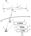
- a radar satellite system 100A includes a radar satellite 10, a ground communication device 12, and a ground management device 13.
- the radar satellite system 100A includes four radar satellites 10.
- the number of radar satellites 10 is not limited to this, and may be less than four (any one to three). It may be 5 or more.
- the ground communication device 12 is a known communication device that communicates with the radar satellite 10.
- the radar satellite system 100A schematically shows two ground communication devices 12.
- the ground management device 13 includes a satellite management unit 131 and a radar management unit 132, communicates with the radar satellite 10 via the ground communication device 12, and manages the radar satellite 10. Since the radar satellite 10 has a function as a “satellite” that is a spacecraft and a function as a “radar device” located in outer space, the function of the radar satellite 10 as a “satellite” is satellite management. The function as the “radar device” of the radar satellite 10 is managed and controlled by the radar management unit 132.
- the specific configuration and management control method of the ground management device 13 are not particularly limited, and configurations and management control methods known in the field of spacecraft or ground radar devices can be used.
- the radar satellite system according to the present invention may further include other configurations.
- another radar satellite system 100B according to the present embodiment includes an aircraft 14, in addition to the radar satellite 10, the ground communication device 12, and the ground management device 13.
- a ship 15, a vehicle 16, and a space machine 17 other than the radar satellite 10 are included.
- the aircraft 14, the ship 15, and the vehicle 16 are configured to be able to communicate with the radar satellite 10, the ground management device 13 (the ground communication device 12), or both, and thereby various information obtained by observation of the air-sea region. Can be used to control the aircraft 14, the ship 15, and the vehicle 16.
- the other spacecraft 17 is exemplified by a space station or other satellites, but may be configured to be able to communicate with these other spacecraft 17 and the radar satellite 10 or the ground management device 13 or both.
- various information obtained by the radar satellite 10 can be used for space development.
- radar communication communication by radar waves
- radar communication it is also known that communication by radar waves (radar communication) is possible by adding a modulation signal to the radar waves for communication. Therefore, it is possible to communicate with the aircraft 14, the ship 15, the vehicle 16, and the other spacecraft 17 using the radar wave transmitted from the radar satellite 10. If communication is possible using the radar satellite 10, the radar satellite system 100B can be applied not only to general communication but also to emergency communication when an emergency such as a disaster occurs. .
- the radar satellite system 100B is particularly effective for the control of the aircraft 14 or the ship 15 moving over a wide range on the earth.
- the radar satellite 10 can be used effectively in the field of observing the air-sea region for the purpose of weather observation, disaster response, environmental monitoring, topographic measurement, etc., but, like the radar satellite system 100B, If the vehicle 14 or the vehicle 16 can be controlled from the outer space, it can be used for disaster monitoring, disaster recovery support, or the defense field. For example, when a disaster occurs in a certain area, it is possible to control the aircraft 14 or the vehicle 16 in the disaster occurrence area by the ground management device 13 via the radar satellite 10 while observing the area with the radar satellite 10. It becomes.
- the present invention can be used widely and suitably in the field of observing not only the surface of the earth but also the sky above from the outer space by radar.
Landscapes
- Engineering & Computer Science (AREA)
- Remote Sensing (AREA)
- Radar, Positioning & Navigation (AREA)
- Physics & Mathematics (AREA)
- General Physics & Mathematics (AREA)
- Computer Networks & Wireless Communication (AREA)
- Aviation & Aerospace Engineering (AREA)
- Chemical & Material Sciences (AREA)
- Combustion & Propulsion (AREA)
- Astronomy & Astrophysics (AREA)
- Electromagnetism (AREA)
- Life Sciences & Earth Sciences (AREA)
- Sustainable Development (AREA)
- Evolutionary Computation (AREA)
- Radar Systems Or Details Thereof (AREA)
Abstract
Description
まず、本発明に係るレーダ衛星の基本構成の一例について、図1~図3を参照して具体的に説明する。
図1に示すように、本実施の形態に係るレーダ衛星10は、レーダ部20、バス部30、テザーワイヤ11等を備えている。レーダ部20は、レーダパネルアレイ201および展開トラス構造物202により構成されている。レーダパネルアレイ201は、複数のレーダパネル21により構成される単一の板状構造体であり、展開トラス構造物202により支持されている。図2(A)に部分的に示すように、展開トラス構造物202は、レーダパネル21を支持する側部枠体204を折り畳みおよび展開可能に連結した構造物であり、例えば金属製または複合材料製(CFRP等)のパイプ材およびヒンジ部材(連結部材)等により構成されている。また、レーダ部20には、レーダスラスタ部40、通信/制御部50、サービスユニット51、補給機52等も設けられている。
次に、レーダ衛星10の制御構成について、図1~図3に加えて図4~図7を参照して具体的に説明する。
前記構成のレーダ衛星10による地球表面およびその上空の観測(空海領域からの情報の取得)について、図8を参照して説明する。図8において一点鎖線で示すように、レーダ衛星10は、例えば高度5,000kmの軌道Osを周回している。図8において破線の双方向矢印C1で示すように、レーダ衛星10は、通信/制御部50により地上と通信可能となっている。
次に、前述したレーダ衛星10を含む本発明に係るレーダ衛星システムの代表的な一例について、図9および図10を参照して具体的に説明する。
11 テザーワイヤ
12 地上通信装置
13 地上管理装置
14 航空機
15 船舶
16 車両
20 レーダ部
21 レーダパネル
22 レーダセル
23 レーダ通信器
24 レーダ電力供給部
25 信号処理器
26 アンテナユニット
30 バス部
31 バススラスタ
32 バススラスタ制御器
33 バス通信器
34 バス電力供給部
40 レーダスラスタ部
41 レーダスラスタ
42 レーダスラスタ制御器
43 レーダスラスタ通信器
50 通信/制御部(通信部)
51 サービスユニット
100A,100B レーダ衛星システム
201 レーダパネルアレイ
202 展開トラス構造物
203 レーダパネルユニット
204 側部枠体
241,341 太陽電池
242,342 バッテリ
243,343 電源制御器
260 パッチアンテナ(アンテナ)
261 送受信ユニット
Claims (8)
- レーダ波を送受信する複数のアンテナおよび太陽電池を備えるレーダパネルを複数連結して単一の平板状に構成されるレーダ部と、
地上または宇宙機と通信を行う通信部と、を備え、
前記レーダ部は、
複数の前記レーダパネルにより構成される板状構造体であるレーダパネルアレイと、
前記レーダパネルを支持する側部枠体を複数、折り畳みおよび展開可能に連結して構成される展開トラス構造物と、
を備えていることを特徴とする、
レーダ衛星。 - 前記レーダ部は、
前記側部枠体によって支持された複数の前記レーダパネルの一辺が屈曲可能な節点で連結され、当該節点でこれらレーダパネルが屈曲されて互いに密接されるように折り畳まれたレーダパネルユニットが展開されたものが、複数連結された構成であるか、または、
展開された展開トラス構造物を構成する複数の前記側部枠体に、それぞれ前記レーダパネルが取り付けられた構成であることを特徴とする、
請求項1に記載のレーダ衛星。 - 前記レーダ部の軌道修正および姿勢制御を行うスラスタ部と、
前記スラスタ部および前記レーダ部の作動制御を行うレーダ制御部と、
を備えることを特徴とする、
請求項1または2に記載のレーダ衛星。 - 前記レーダ部のカウンターウェイトであるバス部と、
前記レーダ部および前記バス部を連結するテザーワイヤと、
を備えていることを特徴とする、
請求項1から3のいずれか1項に記載のレーダ衛星。 - 前記レーダパネルは、前記太陽電池で発電された電力を充電する充電器と、当該充電器の充放電を少なくとも制御する電源制御器と、を備えていることを特徴とする、
請求項1から4のいずれか1項に記載のレーダ衛星。 - 展開された前記レーダパネルユニットを連結して前記レーダ部を構築するとともに、構築された当該レーダ部を維持するサービスユニットを備えていることを特徴とする、
請求項1から5のいずれか1項に記載のレーダ衛星。 - 請求項1から6のいずれか1項に記載のレーダ衛星と、
当該レーダ衛星との間で通信を行う地上通信装置と、
当該地上通信装置を介して前記レーダ衛星の管理を行う地上管理装置と、
を備えていることを特徴とする、
レーダ衛星システム。 - さらに、前記レーダ衛星または前記地上管理装置との間で通信を可能とする航空機、船舶、および車両の少なくともいずれかを含むことを特徴とする、
請求項7に記載のレーダ衛星システム。
Priority Applications (3)
| Application Number | Priority Date | Filing Date | Title |
|---|---|---|---|
| JP2016559801A JP6550073B2 (ja) | 2014-11-18 | 2015-11-09 | レーダ衛星およびこれを用いたレーダ衛星システム |
| US15/527,042 US10871560B2 (en) | 2014-11-18 | 2015-11-09 | Radar satellite and radar satellite system using radar satellite |
| EP15861404.0A EP3222531B1 (en) | 2014-11-18 | 2015-11-09 | Radar satellite and radar satellite system using same |
Applications Claiming Priority (2)
| Application Number | Priority Date | Filing Date | Title |
|---|---|---|---|
| JP2014233447 | 2014-11-18 | ||
| JP2014-233447 | 2014-11-18 |
Publications (1)
| Publication Number | Publication Date |
|---|---|
| WO2016079945A1 true WO2016079945A1 (ja) | 2016-05-26 |
Family
ID=56013520
Family Applications (1)
| Application Number | Title | Priority Date | Filing Date |
|---|---|---|---|
| PCT/JP2015/005584 Ceased WO2016079945A1 (ja) | 2014-11-18 | 2015-11-09 | レーダ衛星およびこれを用いたレーダ衛星システム |
Country Status (4)
| Country | Link |
|---|---|
| US (1) | US10871560B2 (ja) |
| EP (1) | EP3222531B1 (ja) |
| JP (1) | JP6550073B2 (ja) |
| WO (1) | WO2016079945A1 (ja) |
Cited By (1)
| Publication number | Priority date | Publication date | Assignee | Title |
|---|---|---|---|---|
| JPWO2021090361A1 (ja) * | 2019-11-05 | 2021-05-14 |
Families Citing this family (10)
| Publication number | Priority date | Publication date | Assignee | Title |
|---|---|---|---|---|
| US10389019B2 (en) * | 2016-12-17 | 2019-08-20 | Point Road Solutions, Llc | Methods and systems for wet radome attenuation mitigation in phased-array antennae applications and networked use of such applications |
| US12146979B2 (en) | 2017-03-31 | 2024-11-19 | The Tomorrow Companies Inc. | Conical scan weather radar |
| CN108663660A (zh) * | 2018-06-13 | 2018-10-16 | 安徽尼古拉电子科技有限公司 | 一种折叠便携式雷达 |
| GB2578793B (en) * | 2018-11-09 | 2021-04-07 | Iceye Oy | Satellite, manufacturing method and modules for use in satellite assembly |
| CN110609277A (zh) * | 2019-09-24 | 2019-12-24 | 中国船舶重工集团公司第七0七研究所 | 防止雷达纵摇导致卫导信号失锁的雷达卫导安装结构 |
| EP4127772A4 (en) * | 2020-03-31 | 2024-04-10 | The Tomorrow Companies Inc. | WEATHER RADAR WITH CONICAL SCANNING |
| CN111152938B (zh) * | 2020-04-08 | 2020-08-07 | 北京前沿探索深空科技有限公司 | 一种卫星结构 |
| CN112093081B (zh) * | 2020-09-27 | 2021-11-09 | 中国科学院微小卫星创新研究院 | 一种太阳翼微波遥感一体化载荷及其控制方法 |
| CN112748406B (zh) * | 2020-12-24 | 2023-06-13 | 中国电子科技集团公司第三十八研究所 | 一种星载雷达综合数字处理装置 |
| CN118841735B (zh) * | 2024-09-05 | 2025-11-28 | 北京钧天航宇技术有限公司 | 一种星载通信一体板和通信卫星 |
Citations (9)
| Publication number | Priority date | Publication date | Assignee | Title |
|---|---|---|---|---|
| JPS60257603A (ja) * | 1984-06-02 | 1985-12-19 | Natl Space Dev Agency Japan<Nasda> | 合成開口レ−ダアンテナ |
| JPH11505696A (ja) * | 1996-03-20 | 1999-05-21 | サントル、ナショナル、デチュード、スパシアル | 遠隔探知または遠距離通信衛星の改良 |
| US6400306B1 (en) * | 1999-12-17 | 2002-06-04 | Sicom Systems, Ltd | Multi-channel moving target radar detection and imaging apparatus and method |
| JP2006177907A (ja) * | 2004-12-24 | 2006-07-06 | Nec Corp | 干渉型レーダー |
| JP4247755B2 (ja) * | 1998-02-24 | 2009-04-02 | 独立行政法人 宇宙航空研究開発機構 | 展開トラス構造及びアンテナ反射鏡 |
| US7694486B2 (en) * | 2003-12-12 | 2010-04-13 | Alliant Techsystems Inc. | Deployable truss having second order augmentation |
| CN102081156A (zh) * | 2009-11-30 | 2011-06-01 | 上海卫星工程研究所 | 合成孔径雷达卫星的驱动机构 |
| US8035573B2 (en) * | 2007-12-04 | 2011-10-11 | Agence Spatiale Europeenne | Deployable panel structure for an array antenna |
| JP2014184813A (ja) * | 2013-03-22 | 2014-10-02 | Kawasaki Heavy Ind Ltd | サービスユニット |
Family Cites Families (13)
| Publication number | Priority date | Publication date | Assignee | Title |
|---|---|---|---|---|
| US4163231A (en) * | 1968-01-03 | 1979-07-31 | Raytheon Company | Radar mapping technique |
| JP3178744B2 (ja) * | 1992-09-08 | 2001-06-25 | 宇宙開発事業団 | 衛星搭載用アレーアンテナ |
| US5621415A (en) * | 1994-11-15 | 1997-04-15 | Teledesic Corporation | Linear cell satellite system |
| DE19938199C1 (de) * | 1999-08-12 | 2001-01-25 | Inst Solare Energieversorgungstechnik Iset | Vorrichtung zur Umwandlung von Solarnergie in elektrische Energie und zum Abstrahlen und/oder Empfangen von hochfrequenten elektromagnetischen Wellen |
| WO2001084249A2 (en) * | 2000-05-04 | 2001-11-08 | Rosae, Inc. | Apparatus and method for microwave interferometry radiating incrementally accumulating holography |
| US7474249B1 (en) * | 2004-08-12 | 2009-01-06 | Lockheed Martin Corporation | Systems and methods for dedicating power to a radar module |
| US7486224B2 (en) * | 2005-06-30 | 2009-02-03 | United States Of America As Represented By The Secretary Of The Navy | Microwave and millimeter frequency bistatic radar tracking and fire control system |
| US20070145195A1 (en) * | 2005-12-23 | 2007-06-28 | Northrop Grumman Space & Mission Systems Corporation | Deployable array support structure |
| JP4834842B2 (ja) * | 2007-11-09 | 2011-12-14 | Nec東芝スペースシステム株式会社 | 電源制御装置 |
| JP5651006B2 (ja) | 2010-12-24 | 2015-01-07 | 川崎重工業株式会社 | 展開装置を備えた大型展開構造物 |
| US8813455B2 (en) * | 2011-12-07 | 2014-08-26 | Donald V. Merrifield | Deployable truss with orthogonally-hinged primary chords |
| JP6137674B2 (ja) | 2013-03-22 | 2017-05-31 | 川崎重工業株式会社 | 展開装置 |
| US20150285897A1 (en) * | 2014-03-31 | 2015-10-08 | Honeywell International Inc. | Hybrid radar system combining fmcw radar and pulsed radar |
-
2015
- 2015-11-09 JP JP2016559801A patent/JP6550073B2/ja active Active
- 2015-11-09 EP EP15861404.0A patent/EP3222531B1/en active Active
- 2015-11-09 WO PCT/JP2015/005584 patent/WO2016079945A1/ja not_active Ceased
- 2015-11-09 US US15/527,042 patent/US10871560B2/en active Active
Patent Citations (9)
| Publication number | Priority date | Publication date | Assignee | Title |
|---|---|---|---|---|
| JPS60257603A (ja) * | 1984-06-02 | 1985-12-19 | Natl Space Dev Agency Japan<Nasda> | 合成開口レ−ダアンテナ |
| JPH11505696A (ja) * | 1996-03-20 | 1999-05-21 | サントル、ナショナル、デチュード、スパシアル | 遠隔探知または遠距離通信衛星の改良 |
| JP4247755B2 (ja) * | 1998-02-24 | 2009-04-02 | 独立行政法人 宇宙航空研究開発機構 | 展開トラス構造及びアンテナ反射鏡 |
| US6400306B1 (en) * | 1999-12-17 | 2002-06-04 | Sicom Systems, Ltd | Multi-channel moving target radar detection and imaging apparatus and method |
| US7694486B2 (en) * | 2003-12-12 | 2010-04-13 | Alliant Techsystems Inc. | Deployable truss having second order augmentation |
| JP2006177907A (ja) * | 2004-12-24 | 2006-07-06 | Nec Corp | 干渉型レーダー |
| US8035573B2 (en) * | 2007-12-04 | 2011-10-11 | Agence Spatiale Europeenne | Deployable panel structure for an array antenna |
| CN102081156A (zh) * | 2009-11-30 | 2011-06-01 | 上海卫星工程研究所 | 合成孔径雷达卫星的驱动机构 |
| JP2014184813A (ja) * | 2013-03-22 | 2014-10-02 | Kawasaki Heavy Ind Ltd | サービスユニット |
Non-Patent Citations (1)
| Title |
|---|
| See also references of EP3222531A4 * |
Cited By (4)
| Publication number | Priority date | Publication date | Assignee | Title |
|---|---|---|---|---|
| JPWO2021090361A1 (ja) * | 2019-11-05 | 2021-05-14 | ||
| WO2021090361A1 (ja) * | 2019-11-05 | 2021-05-14 | 株式会社Qps研究所 | 宇宙航行体 |
| JP7179197B2 (ja) | 2019-11-05 | 2022-11-28 | 株式会社Qps研究所 | 宇宙航行体 |
| US12187459B2 (en) | 2019-11-05 | 2025-01-07 | Institute For Q-Shu Pioneers Of Space, Inc. | Spacecraft |
Also Published As
| Publication number | Publication date |
|---|---|
| JP6550073B2 (ja) | 2019-07-24 |
| JPWO2016079945A1 (ja) | 2017-08-17 |
| EP3222531A4 (en) | 2018-06-20 |
| EP3222531B1 (en) | 2023-01-04 |
| US10871560B2 (en) | 2020-12-22 |
| US20180246202A1 (en) | 2018-08-30 |
| EP3222531A1 (en) | 2017-09-27 |
Similar Documents
| Publication | Publication Date | Title |
|---|---|---|
| JP6550073B2 (ja) | レーダ衛星およびこれを用いたレーダ衛星システム | |
| KR100971096B1 (ko) | 경량의 공간-피딩된 능동 위상 어레이 안테나 시스템 | |
| Wang et al. | Space phased array antenna developments: A perspective on structural design | |
| Gao et al. | Advanced antennas for small satellites | |
| Das et al. | Techsat 21-space missions using collaborating constellations of satellites | |
| US10680310B2 (en) | Balloon reflector antenna | |
| EP4031905B1 (en) | Satellite borne synthetic aperture radar | |
| GB2455311A (en) | Deployable panel structure | |
| WO2019018085A1 (en) | SPACE SYSTEM BASED ON REFORMABLE, RECONSTITUTEABLE, RECONFIGURABLE CELLS WITH MUTUAL LOCKOUT | |
| US11563269B2 (en) | Phased array antenna and apparatus incorporating the same | |
| JP2017518723A (ja) | 大規模宇宙太陽光発電所:誘導可能ビームを用いる送電 | |
| US7837153B2 (en) | Local observable area and self inspection system | |
| WO2023014800A1 (en) | Multi-direction deployable antenna | |
| Simons et al. | Applications of nano-satellites and cube-satellites in microwave and RF domain | |
| Zheng et al. | A novel space large deployable paraboloid structure with power and communication integration | |
| EP4074607B1 (en) | Spacecraft | |
| Van't Klooster et al. | Large deployable reflector configuration for spacebased applications in telecommunications, science, and remote sensing | |
| Babuscia et al. | Inflatable antenna for cubesat: Motivation for development and initial trade study | |
| You et al. | Design Case of Typical Spacecraft Antenna System | |
| Schultz et al. | Deployable antenna phase A study | |
| 山田慎二 et al. | Communications Technologies Supporting Satellite Communications |
Legal Events
| Date | Code | Title | Description |
|---|---|---|---|
| 121 | Ep: the epo has been informed by wipo that ep was designated in this application |
Ref document number: 15861404 Country of ref document: EP Kind code of ref document: A1 |
|
| ENP | Entry into the national phase |
Ref document number: 2016559801 Country of ref document: JP Kind code of ref document: A |
|
| REEP | Request for entry into the european phase |
Ref document number: 2015861404 Country of ref document: EP |
|
| WWE | Wipo information: entry into national phase |
Ref document number: 15527042 Country of ref document: US |
|
| NENP | Non-entry into the national phase |
Ref country code: DE |