WO2016080060A1 - 装置 - Google Patents
装置 Download PDFInfo
- Publication number
- WO2016080060A1 WO2016080060A1 PCT/JP2015/076067 JP2015076067W WO2016080060A1 WO 2016080060 A1 WO2016080060 A1 WO 2016080060A1 JP 2015076067 W JP2015076067 W JP 2015076067W WO 2016080060 A1 WO2016080060 A1 WO 2016080060A1
- Authority
- WO
- WIPO (PCT)
- Prior art keywords
- cell
- user
- terminal device
- base station
- interference
- Prior art date
- Legal status (The legal status is an assumption and is not a legal conclusion. Google has not performed a legal analysis and makes no representation as to the accuracy of the status listed.)
- Ceased
Links
Images












Classifications
-
- H—ELECTRICITY
- H04—ELECTRIC COMMUNICATION TECHNIQUE
- H04W—WIRELESS COMMUNICATION NETWORKS
- H04W24/00—Supervisory, monitoring or testing arrangements
- H04W24/10—Scheduling measurement reports ; Arrangements for measurement reports
-
- H—ELECTRICITY
- H04—ELECTRIC COMMUNICATION TECHNIQUE
- H04B—TRANSMISSION
- H04B7/00—Radio transmission systems, i.e. using radiation field
- H04B7/02—Diversity systems; Multi-antenna system, i.e. transmission or reception using multiple antennas
- H04B7/04—Diversity systems; Multi-antenna system, i.e. transmission or reception using multiple antennas using two or more spaced independent antennas
- H04B7/0413—MIMO systems
- H04B7/0452—Multi-user MIMO systems
-
- H—ELECTRICITY
- H04—ELECTRIC COMMUNICATION TECHNIQUE
- H04J—MULTIPLEX COMMUNICATION
- H04J11/00—Orthogonal multiplex systems, e.g. using WALSH codes
- H04J11/0023—Interference mitigation or co-ordination
- H04J11/0026—Interference mitigation or co-ordination of multi-user interference
- H04J11/0036—Interference mitigation or co-ordination of multi-user interference at the receiver
-
- H—ELECTRICITY
- H04—ELECTRIC COMMUNICATION TECHNIQUE
- H04W—WIRELESS COMMUNICATION NETWORKS
- H04W36/00—Hand-off or reselection arrangements
- H04W36/0005—Control or signalling for completing the hand-off
- H04W36/0083—Determination of parameters used for hand-off, e.g. generation or modification of neighbour cell lists
- H04W36/00837—Determination of triggering parameters for hand-off
-
- H—ELECTRICITY
- H04—ELECTRIC COMMUNICATION TECHNIQUE
- H04W—WIRELESS COMMUNICATION NETWORKS
- H04W36/00—Hand-off or reselection arrangements
- H04W36/0005—Control or signalling for completing the hand-off
- H04W36/0083—Determination of parameters used for hand-off, e.g. generation or modification of neighbour cell lists
- H04W36/0085—Hand-off measurements
- H04W36/0094—Definition of hand-off measurement parameters
-
- H—ELECTRICITY
- H04—ELECTRIC COMMUNICATION TECHNIQUE
- H04W—WIRELESS COMMUNICATION NETWORKS
- H04W8/00—Network data management
- H04W8/22—Processing or transfer of terminal data, e.g. status or physical capabilities
- H04W8/24—Transfer of terminal data
-
- H—ELECTRICITY
- H04—ELECTRIC COMMUNICATION TECHNIQUE
- H04W—WIRELESS COMMUNICATION NETWORKS
- H04W84/00—Network topologies
- H04W84/02—Hierarchically pre-organised networks, e.g. paging networks, cellular networks, WLAN [Wireless Local Area Network] or WLL [Wireless Local Loop]
- H04W84/04—Large scale networks; Deep hierarchical networks
- H04W84/042—Public Land Mobile systems, e.g. cellular systems
- H04W84/045—Public Land Mobile systems, e.g. cellular systems using private Base Stations, e.g. femto Base Stations, home Node B
Definitions
- This disclosure relates to an apparatus.
- Non-Orthogonal Multiple Access is a radio access technology (RAT) for 5th generation (5G) mobile communication systems following LTE (Long Term Evolution) / LTE-A (Advanced). Attention has been paid.
- OFDMA Orthogonal Frequency-Division Multiple Access
- SC-FDMA Single-Carrier Frequency-Division Multiple Access
- radio resources for example, resource blocks
- OFDMA Orthogonal Frequency-Division Multiple Access
- SC-FDMA Single-Carrier Frequency-Division Multiple Access
- radio resources for example, resource blocks
- These schemes may be referred to as orthogonal multiple access.
- non-orthogonal multiple access radio resources are allocated to users redundantly.
- user signals interfere with each other, but a signal for each user is extracted by a highly accurate decoding process on the receiving side.
- Non-orthogonal multiple access can theoretically achieve higher cell communication capacity than orthogonal multiple access.
- SPC Superposition Coding multiplexing / multiple access.
- SPC is a method of multiplexing signals assigned different powers on the same radio resource.
- reception processing such as interference cancellation and / or iterative detection is performed in order to receive / decode signals multiplexed on the same radio resource.
- Patent Documents 1 and 2 disclose a technique for setting an amplitude (or power) that enables appropriate demodulation / decoding as a technique equivalent to SPC or SPC.
- Patent Document 3 discloses a technique for enhancing SIC (Successive Interference Cancellation) for receiving multiplexed signals.
- an apparatus including an acquisition unit that acquires parameters for a user related to interference cancellation, and a control unit that performs measurement or measurement report on a cell according to the parameters.
- an acquisition unit that acquires a parameter for a user related to interference cancellation, and a control unit that notifies the user of the parameter that performs measurement or measurement report on a cell according to the parameter.
- FIG. 1 is the 1st explanatory view for explaining an example of processing in a transmitting device which supports SPC. It is the 2nd explanatory view for explaining an example of processing in a transmitting device which supports SPC. It is explanatory drawing for demonstrating an example of the process in the receiver which performs interference removal.
- 2 is an explanatory diagram illustrating an example of a schematic configuration of a system 1 according to an embodiment of the present disclosure.
- FIG. It is explanatory drawing for demonstrating the case where the base station which concerns on the embodiment is a base station of a macrocell. It is explanatory drawing for demonstrating the case where the base station which concerns on the embodiment is a base station of a small cell.
- FIGS. 1 and 2 are explanatory diagrams for explaining an example of processing in a transmission device that supports SPC.
- each bitstream eg, transport block
- user A user A
- user B user B
- user C is processed.
- some processing eg, as shown in FIG. 2
- CRC Cyclic Redundancy Check
- FEC Forward Error Correction
- layer mapping For example, layer mapping, power allocation, precoding, SPC multiplexing, resource element mapping, IDFT (Inverse Discrete Fourier Transform) / IFFT (Inverse Fast Fourier Transform), CP (Cyclic Prefix) insertion, and digital to analog and RF (Radio) Conversion to Frequency) is performed.
- IDFT Inverse Discrete Fourier Transform
- IFFT Inverse Fast Fourier Transform
- CP Cyclic Prefix
- power is allocated to the signals of user A, user B, and user C, and in SPC multiplexing, the signals of user A, user B, and user C are multiplexed.
- FIG. 3 is an explanatory diagram for explaining an example of processing in the receiving device that performs interference cancellation.
- conversion from RF and analog to digital CP removal (removal), DFT (Discrete Fourier Transform) / FFT (Fast Fourier Transform), joint interference removal, equalization and decoding are performed. Is called.
- bit streams for example, transport blocks
- the index of the cell to which the target user u is connected is represented by i, and the number of transmission antennas of the base station corresponding to the cell is represented by N TX, i .
- Each of the transmit antennas may be referred to as a transmit antenna port.
- the transmission signal from cell i to user u can be represented in vector form as follows:
- N SS, u is the number of spatial transmission streams for user u.
- N SS, u is a positive integer less than N TX, i .
- the vector x i, u is a spatial stream signal to the user u.
- Each element of this vector basically corresponds to a digital modulation symbol such as PSK (Phase Shift Keying) or QAM (Quadrature Amplitude Modulation).
- the matrix W i, u is a precoding matrix for the user u. Elements in this matrix are basically complex numbers, but may be real numbers.
- Matrix P i, u is a power allocation coefficient matrix for user u in cell i.
- each element is preferably a positive real number.
- this matrix may be a diagonal matrix (that is, a matrix in which other than the diagonal component is 0) as follows.
- the scalar value P i, u may be used instead of the matrix P i, u .
- the cell i includes not only the user u but also other users v, and the signals s i, v of the other users v are also transmitted using the same radio resource. These signals are multiplexed by SPC. Signal s i from cell i after multiplexing is expressed as follows.
- U i is a set of users multiplexed in cell i.
- a transmission signal s j is generated in a cell j (cell serving as an interference source for the user u) other than the serving cell of the user u. On the user side, such a signal is received as interference.
- Received signal r u of the user u may be expressed as follows.
- the matrix H u, i is the channel response matrix for cell i and user u.
- Each element of the matrix H u, i is basically a complex number.
- the vector n u is noise included in the received signal r u of the user u.
- the noise includes thermal noise and interference from other systems.
- the average power of noise is expressed as follows.
- Received signal r u as follows, can be represented by the desired signal and other signals.
- the first term on the right side is the desired signal of the user u
- the second term is the interference in the serving cell i of the user u (intra-cell interference, multi-user interference or multi-access)
- the third term is interference from cells other than the cell i (called inter-cell interference).
- the received signal can be expressed as follows.
- orthogonal multiple access there is no intra-cell interference, and signals of other users v are not multiplexed in the same radio resource in other cells j.
- FIG. 4 is an explanatory diagram illustrating an example of a schematic configuration of the system 1 according to the embodiment of the present disclosure.
- the system 1 includes a base station 100 and a terminal device 200.
- the terminal device 200 is also called a user.
- the user may also be called user equipment (UE).
- the UE here may be a UE in LTE or LTE-A, and may more generally mean a communication device.
- Base station 100 is a base station of a cellular system (or mobile communication system).
- the base station 100 performs wireless communication with a terminal device (for example, the terminal device 200) located in the cell 101 of the base station 100.
- a terminal device for example, the terminal device 200
- the base station 100 transmits a downlink signal to the terminal device and receives an uplink signal from the terminal device.
- Terminal device 200 The terminal device 200 can communicate in a cellular system (or mobile communication system).
- the terminal device 200 performs wireless communication with a base station (for example, the base station 100) of the cellular system.
- a base station for example, the base station 100
- the terminal device 200 receives a downlink signal from the base station and transmits an uplink signal to the base station.
- the base station 100 is a macro cell base station. That is, the cell 101 is a macro cell.
- the cell 101 is a macro cell.
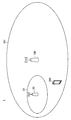
- FIG. 5 is an explanatory diagram for explaining a case where the base station 100 is a macro cell base station.
- a base station 100 and a terminal device 200 are shown.
- the base station 100 is a macro cell base station
- the cell 101 is a macro cell overlapping the small cell 21.
- the terminal device 200 can perform wireless communication with the base station 20 of the small cell 21.
- the base station 100 may be a small cell base station. That is, the cell 101 may be a small cell.
- the cell 101 may be a small cell.
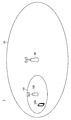
- FIG. 6 is an explanatory diagram for explaining a case where the base station 100 is a small cell base station.
- a base station 100 and a terminal device 200 are shown.
- the base station 100 is a small cell base station
- the cell 101 is a small cell overlapping the macro cell 31.
- the terminal device 200 can perform wireless communication with the base station 30 of the macro cell 31.
- (C) Frequency band For example, in the macro cell and the small cell, the same frequency band (for example, the same component carrier) is used. That is, the same frequency band is shared between the macro cell and the small cell.
- the same frequency band for example, the same component carrier
- different frequency bands may be used in the macro cell and the small cell.
- the terminal device 200 performs measurement on a cell.
- the cell may be a serving cell for the terminal device 200 or a neighbor cell.
- the measurement includes measurement of received power for a cell. More specifically, for example, the measurement includes measurement of received power of a reference signal. As an example, the measurement includes measurement of RSRP (Reference Signal Received Power). RSRP is calculated as follows, for example.
- r cell (f, t) is a received signal of the resource element of frequency index f and time index t.
- FRS Cell is a set of frequency indexes
- TRS Cell is a set of time indexes.
- E ⁇ means average processing.
- the RSRP may be a linear value or a decibel value.
- the averaging process is preferably an averaging process using a linear value.
- the measurement includes measurement of communication quality for a cell. More specifically, for example, the measurement includes measurement of reception quality of a reference signal. As an example, the measurement includes measurement of RSRQ (Reference Signal Received Quality).
- the measurement may include measurement of SNR (Signal-to-Noise Ratio), SINR (Signal-to-Interference-plus-Noise Ratio), CSI (Channel State Information), and / or CQI (Channel Quality Indicator). Good.
- RSRQ is calculated as follows, for example.
- RSSI is the power of the received signal over the channel bandwidth and is calculated as follows.
- R (t) is the received signal of time index t.
- E ⁇ means average processing.
- the RSSI may be a linear value or a decibel value.
- the averaging process is preferably an averaging process using a linear value.
- the reference signal is a CRS / CSRS (Cell-specific Reference Signal).
- the reference signal may be DRS / DMRS (Demodulation Reference Signal), CSIRS (Channel State Information Reference Signal), or PRS (Positioning Reference Signal).
- the terminal device 200 performs a measurement report on a cell. That is, the terminal device 200 reports (or feeds back) the measurement result to the base station.
- the base station is a serving cell base station (for example, base station 100) for the terminal device 200.
- the terminal device 200 performs a measurement report when a predetermined event condition is satisfied.
- the predetermined event is any one of events A1 to A6 and B1 to B2 defined by 3GPP (Third Generation Partnership Project).
- the predetermined event may be different.
- the terminal device 200 may report values (eg, RSRP and RSRQ) that are measurement results themselves, or may report an index corresponding to the values that are measurement results.
- values eg, RSRP and RSRQ
- the base station 100 selects a cell for the terminal device 200 (that is, a user). For example, the base station 100 selects a cell based on the measurement result reported by the terminal device 200.
- the base station 100 selects a target cell for handover of the terminal device 200. That is, the base station 100 determines handover of the terminal device 200 to the target cell.
- the handover may be an inter-base station handover or an inter-frequency handover.
- the base station 100 selects a secondary cell (or secondary component carrier) for the terminal device 200. That is, the base station 100 determines addition or deletion of a secondary cell for the terminal device 200.
- the base station 100 performs wireless communication with a plurality of terminal devices by orthogonal multiple access.
- the orthogonal multiple access is OFDMA.
- the orthogonal multiple access may be FDMA (Frequency Division Multiple Access) or TDMA (Time Division Multiple Access).
- the base station 100 may perform wireless communication with a plurality of terminal devices by non-orthogonal multiple access.
- the non-orthogonal multiple access may be an SPC multiple access.
- Interference removal when the terminal device 200 has interference removal capability, the terminal device 200 removes interference from the received signal. More specifically, for example, the terminal device 200 removes inter-cell interference (that is, interference from neighboring cells) from the received signal. When non-orthogonal multiple access is used, the terminal device 200 may remove intra-cell interference from the received signal.
- inter-cell interference that is, interference from neighboring cells
- the terminal device 200 may remove intra-cell interference from the received signal.
- the terminal device 200 when the terminal device 200 does not have interference removal capability, the terminal device 200 does not remove interference from the received signal.
- interference removal may be a method of generating and removing a replica of an interference signal for a desired signal (that is, interference removal in a narrow sense), or such a narrow sense.
- interference removal a technique that further includes interference suppression (ie, interference removal in a broad sense) may be used.
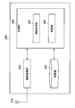
- FIG. 7 is a block diagram illustrating an exemplary configuration of the base station 100 according to the embodiment of the present disclosure.
- the base station 100 includes an antenna unit 110, a wireless communication unit 120, a network communication unit 130, a storage unit 140, and a processing unit 150.
- Antenna unit 110 The antenna unit 110 radiates a signal output from the wireless communication unit 120 to the space as a radio wave. Further, the antenna unit 110 converts radio waves in space into a signal and outputs the signal to the wireless communication unit 120.
- the wireless communication unit 120 transmits and receives signals.
- the radio communication unit 120 transmits a downlink signal to the terminal device and receives an uplink signal from the terminal device.
- the network communication unit 130 transmits and receives information.
- the network communication unit 130 transmits information to other nodes and receives information from other nodes.
- the other nodes include other base stations and core network nodes.
- Storage unit 140 The storage unit 140 temporarily or permanently stores a program for operating the base station 100 and various data.
- Processing unit 150 provides various functions of the base station 100.
- the processing unit 150 includes an information acquisition unit 151 and a control unit 153.
- the processing unit 150 may further include other components other than these components. That is, the processing unit 150 can perform operations other than the operations of these components.
- the information acquisition unit 151 and the control unit 153 will be described in detail later.
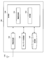
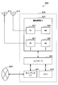
- FIG. 8 is a block diagram illustrating an exemplary configuration of the terminal device 200 according to an embodiment of the present disclosure.
- the terminal device 200 includes an antenna unit 210, a wireless communication unit 220, a storage unit 230, and a processing unit 240.
- Antenna unit 210 The antenna unit 210 radiates the signal output from the wireless communication unit 220 to the space as a radio wave. Further, the antenna unit 210 converts a radio wave in the space into a signal and outputs the signal to the wireless communication unit 220.
- the wireless communication unit 220 transmits and receives signals.
- the radio communication unit 220 receives a downlink signal from the base station and transmits an uplink signal to the base station.
- Storage unit 230 The storage unit 230 temporarily or permanently stores a program for operating the terminal device 200 and various data.
- the processing unit 240 provides various functions of the terminal device 200.
- the processing unit 240 includes an information acquisition unit 241 and a control unit 243.
- the processing unit 240 may further include other components other than these components. That is, the processing unit 240 can perform operations other than the operations of these components.
- the information acquisition unit 241 and the control unit 243 will be described in detail later.
- the terminal device 200 acquires parameters for the user (hereinafter referred to as “user parameters”) related to interference removal. And the terminal device 200 (control part 243) performs the measurement or measurement report about a cell according to the said user parameter. Note that the user is the terminal device 200.
- the cell may be a serving cell for the user (that is, the terminal device 200) or a neighboring cell for the user (that is, the terminal device 200).
- the user parameter is a value according to the interference removal capability of the user (that is, the terminal device 200).
- the user parameter is larger when the user has interference removal capability, and smaller when the user does not have interference removal capability.
- the user parameter is a value according to the cell or the cell type.
- the user parameter is larger when the cell is a small cell and smaller when the cell is a macro cell.
- the user parameter is an offset (hereinafter referred to as “user offset”) for the user (that is, the terminal device 200) related to interference cancellation.
- the user offset is included in the event condition that triggers the measurement report.
- the terminal device 200 (the control unit 243) performs a measurement report on the cell according to the user offset.
- the user parameter is a timer value for the user (that is, the terminal device 200) related to interference cancellation, and is the timer value set in a timer used for measurement reporting. is there.
- the terminal device 200 (the control unit 243) performs a measurement report on the cell according to the timer value.
- the user parameter is a correction value for the user (that is, the terminal device 200) related to interference removal, and is the correction value used for measuring communication quality.
- the terminal device 200 (control unit 243) measures the communication quality for the cell according to the correction value.
- the base station 100 (information acquisition unit 151) acquires parameters (that is, user parameters) for the user (that is, the terminal device 200) related to interference cancellation. Then, the base station 100 (the control unit 153) notifies the user (that is, the terminal device 200) that performs measurement or measurement report on the cell according to the user parameter with the parameter.
- parameters that is, user parameters
- the base station 100 (the control unit 153) notifies the user (that is, the terminal device 200) that performs measurement or measurement report on the cell according to the user parameter with the parameter.
- the terminal device 200 notifies the base station 100 of the interference removal capability of the terminal device 200 (that is, the user), and the base station 100 (processing unit 150) determines the user parameter based on the capability. Then, the base station 100 (information acquisition unit 151) acquires the user parameter, and the base station 100 (control unit 153) notifies the terminal device 200 (that is, the user) of the user parameter.
- the base station 100 notifies the terminal device 200 of the user parameter by individual signaling to the terminal device 200. Specifically, for example, the base station 100 transmits a message including the user parameter to the terminal device 200.
- the base station 100 may broadcast two or more user parameter candidates. Specifically, the base station 100 may transmit system information including the two or more user parameter candidates. Then, the terminal device 200 may select one of the two or more user parameter candidates (for example, based on the interference removal capability of the terminal device 200) as its own user parameter. Or the terminal device 200 may hold
- the user parameter is an offset (that is, user offset) for the user (that is, the terminal device 200) related to interference cancellation.
- the user offset is included in the event condition that triggers the measurement report.
- the terminal device 200 (the control unit 243) performs a measurement report on the cell according to the user offset.
- the user offset is a value added to the measurement result under the above conditions.
- the measurement result is the received power of the reference signal or the received quality of the reference signal.
- the user offset is included in the condition of the event that triggers the measurement report, and is added to RSRP or RSRQ in the condition.
- the event is any one of events A1 to A6 and B1 to B2 defined in 3GPP. That is, the user offset is applied to one or more of the events A1 to A6 and B1 to B2.
- Event A1 is an event in which the measurement result for the serving cell exceeds the threshold value.
- the condition for the event A1 is expressed as follows.
- Ms is a measurement result (for example, RSRQ or RSRP) for the serving cell
- Ou is a user offset
- Hys is a hysteresis for avoiding frequent occurrence of events
- Thresh is It is a threshold value.
- the event A1 is more likely to occur (that is, the condition of the event A1 is more easily satisfied).
- the user offset Ou is smaller, the event A1 is less likely to occur (that is, the condition of the event A1 is less likely to be satisfied).
- Event A2 is an event in which the measurement result for the serving cell falls below the threshold value.
- the condition for the event A2 is expressed as follows.
- the event A2 is less likely to occur (that is, the condition of the event A2 is less likely to be satisfied).
- the user offset Ou is smaller, the event A2 is more likely to occur (that is, the condition of the event A1 is more easily satisfied).
- Event A3 is an event in which the measurement result for the neighboring cell exceeds the measurement result for the serving cell by an offset. For example, when the user offset is applied to the event A3, the condition for the event A3 is expressed as follows.
- Mn is a measurement result (for example, RSRQ or RSRP) for the neighboring cell
- Ofn is a frequency offset for the frequency of the neighboring cell
- Oct is a cell offset for the neighboring cell.
- Oun is a user offset corresponding to the neighboring cell
- Hys is a hysteresis for avoiding frequent occurrence of events.
- Mp is a measurement result (for example, RSRQ or RSRP) for the primary cell
- Ofp is a frequency offset for the frequency of the primary cell
- Ocp is for the primary cell. It is a cell offset
- Oup is a user offset corresponding to the primary cell.
- Off is the offset of event A3.
- the primary cell is one of the serving cells.
- the event A3 is more likely to occur (that is, the condition of the event A3 is more easily satisfied).
- the event A3 is less likely to occur (that is, the condition of the event A3 is less likely to be satisfied).
- condition for occurrence of the event A3 can be expressed as follows.
- Event A4 is an event that the measurement result of the neighboring cell exceeds the threshold value. For example, when the user offset is applied to the event A4, the condition for the event A4 is expressed as follows.
- the event A4 is more likely to occur (that is, the condition of the event A4 is more easily satisfied).
- the user offset “Oun” is smaller, the event A4 is less likely to occur (that is, the condition of the event A4 is less likely to be satisfied).
- Event A5 is an event in which the measurement result for the serving cell is below the first threshold value and the measurement result for the neighboring cells is above the second threshold value.
- the condition for the event A5 is expressed as follows.
- Thresh1 is a first threshold value
- Thresh2 is a second threshold value
- the event A5 is less likely to occur (that is, the condition of the event A5 is less likely to be satisfied).
- the larger the user offset Oun corresponding to the neighboring cell the easier it is for the event A5 to occur (that is, the condition for the event A5 is more likely to be satisfied).
- condition for the occurrence of the event A5 can be represented as follows.
- Event A6 is an event in which the measurement result for the neighboring cell exceeds the measurement result for the secondary cell by an offset. For example, when the user offset is applied to the event A6, the condition for the event A6 is expressed as follows.
- Mn is a measurement result (for example, RSRQ or RSRP) for the neighboring cell
- Ofn is a frequency offset for the frequency of the neighboring cell
- Oct is a cell offset for the neighboring cell.
- Oun is a user offset corresponding to the neighboring cell
- Hys is a hysteresis for avoiding frequent occurrence of events.
- Ms is a measurement result (for example, RSRQ or RSRP) for the secondary cell
- Ofs is a frequency offset for the frequency of the secondary cell
- Ocs is for the secondary cell. This is a cell offset
- Oup is a user offset corresponding to the secondary cell.
- Off is the offset of event A6.
- the event A6 is more likely to occur (that is, the condition of the event A6 is more easily satisfied).
- the user offset Ous corresponding to the primary cell is larger, the event A6 is less likely to occur (that is, the condition of the event A6 is less likely to be satisfied).
- Event B1 is an event in which the measurement results for the peripheral cells of different RATs (Radio Access Technology) exceed the threshold value.
- the condition for the event B1 is expressed as follows.
- the event B1 is more likely to occur (that is, the condition of the event B1 is more easily satisfied).
- the user offset “Oun” is smaller, the event B1 is less likely to occur (that is, the condition of the event B1 is less likely to be satisfied).
- Event B2 is an event in which the measurement result for the primary cell is lower than the first threshold value, and the measurement result for neighboring cells of different RATs is higher than the second threshold value.
- the condition for the event B2 is expressed as follows.
- Thresh1 is a first threshold value
- Thresh2 is a second threshold value
- the event B2 is less likely to occur (that is, the condition of the event B2 is less likely to be satisfied).
- the event B2 is more likely to occur (that is, the condition of the event B2 is more easily satisfied).
- the event may be a new event instead of the existing event described above.
- the new event may be an event that is applied only when the user has interference removal capability.
- the first new event and the second new event may be applied under the following conditions.
- one of the serving cell and the peripheral cell is a macro cell, and the other is a small cell.
- the serving cell is a primary cell.
- (C-1) First new event-Conditions for the first new event For example, when the reception power of the user's primary cell is larger than (or more than) the reception power of the neighboring cells, 1 new event is applied.
- the conditions for the first new event are as follows.
- Mp1 is the received power for the primary cell (eg, RSRP)
- Ofp is the frequency offset for the frequency of the primary cell
- Ocp is the cell offset for the primary cell
- Oup is a user offset corresponding to the primary cell.
- Hys is a hysteresis for avoiding frequent events.
- Mn1 is the received power (for example, RSRP) for the neighboring cell
- Mn2 is the communication quality (for example, RSRQ) for the neighboring cell
- Ofn is the frequency for the frequency of the neighboring cell. It is an offset
- Ocn is a cell offset for the peripheral cell
- Oun is a user offset corresponding to the peripheral cell.
- the first new event is more likely to occur (that is, the condition is more easily satisfied).
- the user offset Oup corresponding to the primary cell is larger, the first new event is less likely to occur (that is, the condition is less likely to be satisfied).
- the communication quality Q p of the processes primary cell derived (e.g., SINR) is generally received power P p for the primary cell using the received power P n and the noise n in the peripheral cells, as follows It is expressed in
- the communication quality Q n for the neighboring cells is generally expressed as follows.
- the other signal when the reception power of another signal is larger than the reception power of the target signal, the other signal can be removed as an interference signal. Therefore, when the user has the capability of canceling interference and the received power P p of the primary cell signal (interference signal) is larger than the received power P n of the signal (target signal) of the neighboring cell.
- the communication quality Q n of the neighboring cells can be expressed as follows as a result of interference cancellation.
- the communication quality Q n for the neighboring cells is better than the communication quality Q p of the primary cell, it is desirable to perform handover (that is, change of the primary cell).
- the received power P p , received power P s and communication quality Q n correspond to Mp1, Mn1 and Mn2 in the above condition of the first new event, respectively.
- the condition of the first new event is derived.
- Mp1 is the received power (eg, RSRP) for the primary cell
- Mn2 is the communication quality (eg, RSRQ) for the primary cell
- Ofp is the frequency offset for the frequency of the primary cell
- Oup is a user offset corresponding to the primary cell.
- Hys is a hysteresis for avoiding frequent events.
- Mn1 is the received power (eg, RSRP) for the neighboring cell
- Ofn is the frequency offset for the frequency of the neighboring cell
- Oct is the cell offset for the neighboring cell
- “On” is a user offset corresponding to the peripheral cell.
- the second new event is more likely to occur (that is, the condition is more easily satisfied).
- the second new event is less likely to occur (that is, the condition is less likely to be satisfied).
- the communication quality Q p of the processes primary cell derived (e.g., SINR) is generally received power P p for the primary cell using the received power P n and the noise n in the peripheral cells, as follows It is expressed in
- the other signal when the reception power of another signal is larger than the reception power of the target signal, the other signal can be removed as an interference signal. Therefore, when the user has the capability of interference removal and the received power P n of the signal (interference signal) of the neighboring cell is larger than the received power P p of the signal (target signal) of the primary cell.
- the communication quality Q p of the primary cell can be expressed as follows as a result of interference cancellation.
- the communication quality Q n for the neighboring cells is generally expressed as follows.
- the communication quality Q n for the neighboring cells is better than the communication quality Q p of the primary cell, it is desirable to perform handover (that is, change of the primary cell).
- the received power P p , the communication quality Q p and the received power P n correspond to Mp1, Mp2 and Mn1 in the above condition of the second new event, respectively.
- the condition of the second new event is derived.
- Event state the state of the user related to the event (hereinafter referred to as “event state”) is managed within the user.
- event state the state of the user related to the event.
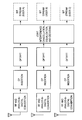
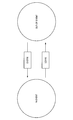
- FIG. 9 is an explanatory diagram for explaining an example of an event state.
- the event state is one of “In-Event” and “Out-of-Event”.
- the event state transitions from “Out-of-Event” to “In-Event”. That is, the user enters “In-Event” (enter).
- the event state transitions from “In-Event” to “Out-of-Event”. That is, the user leaves from “In-Event” (leave).
- the user offset is a value according to the interference removal capability of the user (that is, the terminal device 200).
- the user offset is larger when the user has interference removal capability, and smaller when the user does not have interference removal capability.
- the user offset is a positive value when the user has interference removal capability, and is 0 (or a value smaller than the positive value) when the user does not have interference removal capability. is there.
- the user offset may take one of three values instead of taking one of the two values. In this case, the user offset is a larger value when the user can perform higher-performance interference cancellation, and depending on the case where the user can perform lower-performance interference cancellation. It may be a small value.
- a user having interference removal capability that is, a user who can reduce interference from neighboring cells
- a user who can perform interference cancellation can use the cell even under severe conditions.
- E-2 Value according to cell / cell type
- the user offset is a value according to the cell or the cell type.
- the user offset is larger when the cell is a small cell and smaller when the cell is a macro cell. That is, the user offset is larger when corresponding to a small cell and smaller when corresponding to a macro cell.
- interference removal capability that is, a user capable of reducing interference from neighboring cells
- a small cell more preferentially than a macro cell. That is, a user who can perform interference removal can use the small cell even under severe conditions. Therefore, offloading to the small cell can be promoted.
- the user offset may have different values depending on whether the event occurs or ends. In other words, the user offset may have a value corresponding to the event state.
- the user offset may have a first value in an event occurrence condition and a second value different from the first value in an event end condition.
- the user offset has the first value when the event state is “Out-of-Event”, and has the second value when the event state is “In-Event”. May be.
- CRE Cell Range Extension
- the measurement report according to the user offset enables, for example, CRE for each user.
- CRE is a technique that makes it easy to select a specific cell (or makes it difficult to select a specific cell) by using an offset. It can be said that CRE is a method of adjusting the width of a specific cell by an offset. As an example, a small cell is more easily selected for a user who has the capability of interference cancellation. That is, the size of the small cell is adjusted to be larger.
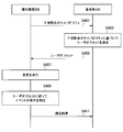
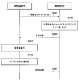
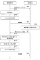
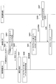
- FIG. 10 is a sequence diagram illustrating an example of a schematic flow of overall processing regarding a measurement report according to a user offset.
- the terminal device 200 notifies the base station 100 of the interference removal capability of the user (that is, the terminal device 200) (S401).
- the base station 100 determines an offset (that is, user offset) for the user (that is, the terminal device 200) related to interference cancellation based on the capability (S403). And the base station 100 notifies the said user offset to the terminal device 200 (S405).
- the terminal device 200 performs measurement on the cell (S407). And the terminal device 200 determines the conditions of the event which triggers the measurement report about the said cell according to the said user offset (S409).
- the terminal device 200 When the above event occurs (that is, when the above condition is satisfied), the terminal device 200 performs a measurement report to the base station 100 (S411). That is, the terminal device 200 reports the measurement result to the base station 100.
- the base station 100 may select a cell for the terminal device 200 based on the measurement result.
- the cell may be a target cell for handover of the terminal device 200. That is, the base station 100 may make a handover decision for the terminal device 200 based on the measurement result.
- the cell may be a secondary cell for the terminal device 200.
- the base station 100 may determine addition or deletion of a secondary cell (secondary component carrier) for the terminal device 200 based on the measurement result.
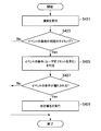
- FIG. 11 is a sequence diagram illustrating an example of a schematic flow of processing of the terminal device 200 regarding a measurement report according to a user offset. This process corresponds to steps S407 to S411 described with reference to FIG.
- the terminal device 200 performs measurement on the cell (S421).
- the terminal device 200 may filter the measurement result as necessary.
- the terminal device 200 determines the event condition that triggers the measurement report according to the user offset (S425).
- the condition includes the user offset.
- the event is any one of events A1 to A6 and B1 to B2. Note that when the terminal device 200 has the capability of interference removal, the event may be the first new event or the second new event described above.
- measurement reports are performed according to user parameters. Thereby, for example, it is possible to perform a measurement report in consideration of interference removal. More specifically, for example, the frequency of measurement reports is adjusted according to whether or not interference cancellation is performed.
- the terminal device 200 performs a measurement report on a cell according to the user offset.
- the base station 100 may select a cell for the user according to the user offset.
- the selection may be selection of a target cell for handover of the user (that is, the terminal device 200). That is, the base station 100 may make a handover decision for the user (that is, the terminal device 200) according to the user offset.
- the information acquisition unit 151 may acquire a user offset, and the control unit 153 may perform handover determination for the user according to the user offset.
- the base station 100 may determine a handover condition according to the user offset.
- the base station 100 may add the user offset to the measurement result and determine the condition based on the value after the addition. And when the said conditions are satisfy
- FIG. 12 is a sequence diagram illustrating an example of a schematic flow of overall processing regarding handover determination according to a user offset.
- the terminal device 200 notifies the base station 100 of the interference removal capability of the user (that is, the terminal device 200) (S441).
- the base station 100 determines an offset (that is, user offset) for the user (that is, the terminal device 200) related to interference cancellation based on the capability (S443).
- the terminal device 200 performs measurement on the cell (S445). And the terminal device 200 determines the conditions of the event which triggers the measurement report about the said cell (S447).
- the terminal device 200 When the above event occurs (that is, when the above condition is satisfied), the terminal device 200 performs a measurement report to the base station 100 (S449). That is, the terminal device 200 reports the measurement result to the base station 100.
- the base station 100 determines a handover condition according to the user offset (S451). As an example, the base station 100 (control unit 153) adds the user offset to the measurement result, and determines the condition based on the value after the addition.
- the base station 100 determines the handover of the user (that is, the terminal device 200) to the target cell (S453). That is, the base station 100 (control unit 153) selects the target cell. Thereafter, the base station 100 (control unit 153) performs a handover procedure (S455).
- FIG. 13 is a sequence diagram showing an example of a schematic flow of processing of the base station 100 regarding handover determination according to a user offset. This process corresponds to steps S451 and S453 described with reference to FIG.
- the base station 100 acquires the measurement result for the cell reported by the user (that is, the terminal device 200) (S461).
- the base station 100 may filter the measurement result as necessary.
- the base station 100 determines the handover conditions for the user according to the user offset (S465).
- the condition includes the user offset.
- the base station 100 determines the handover of the user (that is, the terminal device 200) to the target cell (S469). Otherwise (S467: NO), the process ends.
- the selection may be selection of a secondary cell for the user (that is, the terminal device 200). That is, the base station 100 may determine addition or deletion of a secondary cell for the user (that is, the terminal device 200) according to the user offset.
- the information acquisition unit 151 acquires a user offset.
- the control part 153 may determine the addition or deletion of the secondary cell for a user according to the said user offset.
- the base station 100 may determine the conditions for adding or deleting a secondary cell according to the user offset.
- the base station 100 may add the user offset to the measurement result and determine the condition based on the value after the addition. And when the said conditions are satisfy
- processing related to determination of addition or deletion of secondary cell in accordance with user offset is the above-described “in accordance with user offset” except for the difference between “handover” and “addition or deletion of secondary cell”. This is the same as the flow of “processing related to handover determination”.
- the cell is selected according to the user parameter.
- the cell is selected according to the user parameter.
- the user parameter is the value of the user related to interference cancellation (that is, the terminal device 200).
- the terminal device 200 (control unit 243) performs measurement report on the cell according to the timer value.
- Timer For example, the timer starts when an event condition that triggers a measurement report is satisfied. Further, for example, the timer is reset when the condition is not satisfied.
- the terminal device 200 (control unit 243) performs a measurement report on the cell after the timer expires.
- timer value (b-1) Value according to interference removal capability
- the timer value is a value according to the interference removal capability of the user (that is, the terminal device 200).
- the timer value is larger when the user has interference removal capability, and is smaller when the user does not have interference removal capability. That is, the timer value T IC when having the capability of the user interference cancellation, the timer value T noic when no capabilities of the user interference cancellation, with the following relationship.
- the frequency of handover of the terminal device having the capability of interference cancellation can be reduced. More specifically, for example, a terminal apparatus having the capability of interference cancellation performs measurement reporting on the condition that the event condition continues to be satisfied for a longer time. Therefore, an event occurs, but when the event ends in a short time, the terminal device does not perform a measurement report. Therefore, the frequency of measurement reports decreases, and as a result, the frequency of handovers can also decrease. Since the terminal device having the capability of interference removal can maintain the communication quality even in a somewhat bad environment, such a method can be used.
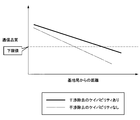
- FIG. 14 is an explanatory diagram for explaining an example of the relationship between interference removal capability and communication quality.
- a relationship between a distance from a base station (for example, a small cell base station) and communication quality is shown.
- Communication quality of communication between the terminal device and the base station decreases as the terminal device moves away from the base station.
- the terminal device has interference removal capability, it is possible to remove interference from other cells (for example, macro cells). Therefore, when the terminal device does not have interference removal capability, the communication quality decreases as the distance from the base station increases when the terminal device has interference removal capability. It becomes more gradual.
- the timer value is a value according to the cell or the cell type.
- the timer value is larger when the serving cell of the user (that is, the terminal device 200) is a small cell, and is smaller when the serving cell is a macro cell. That is, the user of the serving cell is the timer value T IC when it is small cell, Small, T noic, Small and the timer value T IC when a serving cell of the user is a macro cell, Macro, T noic, The Macro, It has the following relationship.
- interference removal capability that is, a user capable of reducing interference from neighboring cells
- a small cell more preferentially than a macro cell. That is, a user who can perform interference removal can use the small cell even under severe conditions. Therefore, offloading to the small cell can be promoted.
- the timer value may be adjusted by a scaling factor.
- the following scaling factors are prepared.
- a timer value T IC when the user has a capability of interference cancellation the timer value T noic when no capabilities of the user interference cancellation, as follows, scaling factors and baseline timer value described above It may be calculated from T Base .
- scaling factor has the following relationship, for example.
- the base station 100 may transmit the baseline timer value T Base and the scaling factor instead of transmitting the timer value itself. Then, the terminal device 200 may calculate a timer value from the baseline timer value T Base and the scaling factor, and perform a measurement report according to the timer value.
- FIG. 15 is a sequence diagram illustrating an example of a schematic flow of overall processing relating to a measurement report according to a timer value.
- the terminal device 200 notifies the base station 100 of the interference removal capability of the user (that is, the terminal device 200) (S481).
- the base station 100 determines a timer value for the user (that is, the terminal device 200) related to interference cancellation based on the capability (S483). Then, the base station 100 notifies the terminal device 200 of the timer value (S485).
- the terminal device 200 performs measurement on the cell (S487). And the terminal device 200 determines the conditions of the event which triggers the measurement report about the said cell (S489).
- the terminal device 200 When the event occurs (that is, when the condition is satisfied), the terminal device 200 performs a measurement report to the base station 100 according to the timer value (S491). That is, the terminal device 200 reports the measurement result to the base station 100 according to the timer value.
- the base station 100 may select a cell for the terminal device 200 based on the measurement result.
- the cell may be a target cell for handover of the terminal device 200. That is, the base station 100 may make a handover decision for the terminal device 200 based on the measurement result.
- the cell may be a secondary cell for the terminal device 200.
- the base station 100 may determine addition or deletion of a secondary cell (secondary component carrier) for the terminal device 200 based on the measurement result.
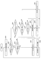
- FIG. 16 is a sequence diagram illustrating a first example of a schematic flow of processing of the terminal device 200 regarding a measurement report according to a user offset. This process corresponds to steps S489 and S491 described with reference to FIG.
- the terminal device 200 determines the condition of the event that triggers the measurement report for the cell (S501).
- the terminal device 200 restarts the timer (S511) and waits until the next determination timing (S513). Thereafter, the process returns to step S501.
- the change in the event state may be a change from “Out-of-Event” to “In-Event” or a change from “In-Event” to “Out-of-Event”. Note that “restarting the timer” means resetting the timer and further starting the timer.
- the terminal device 200 checks whether the timer has already started (S505).
- step S505 If the timer has not yet started (S505: NO), it is considered that a timer error has occurred, so the terminal device 200 (control unit 243) restarts the timer (S511), and the next determination timing. (S513). Thereafter, the process returns to step S501.
- the terminal device 200 checks whether the timer has expired (S507).
- the terminal device 200 (control unit 243) waits until the next determination timing (S513). Thereafter, the process returns to step S501.
- the terminal device 200 If the timer has expired (S507: YES), the terminal device 200 (control unit 243) performs a measurement report to the base station 100 (S509). Thereafter, the terminal device 200 (control unit 243) restarts the timer (S511) and waits for the next determination timing (S513). Thereafter, the process returns to step S501.
- FIG. 17 is a sequence diagram illustrating a second example of a schematic flow of a process of the terminal device 200 regarding a measurement report according to a user offset. This process corresponds to steps S489 and S491 described with reference to FIG. In particular, in the second example, a measurement report is made when the event state changes from “Out-of-Event” to “In-Event”.
- the terminal device 200 determines the condition of the event that triggers the measurement report for the cell (S521).
- the terminal device 200 (control unit 243) waits until the next determination timing (S529). Thereafter, the process returns to step S521.
- the terminal device 200 (control unit 243) checks whether the timer has already been started (S533).
- step S533 If the timer has not yet started (S533: NO), it is considered that a timer error has occurred, so the terminal device 200 (control unit 243) restarts the timer (S541), and the next determination timing. (S529). Thereafter, the process returns to step S521.
- the terminal device 200 checks whether the timer has expired (S535).
- the terminal device 200 (control unit 243) waits until the next determination timing (S529). Thereafter, the process returns to step S521.
- the terminal device 200 When the timer has expired (S535: YES), the terminal device 200 (control unit 243) performs a measurement report to the base station 100 (S537). Thereafter, the terminal device 200 (control unit 243) resets the timer (S539) and waits for the next determination timing (S529). Thereafter, the process returns to step S521.
- a cell is selected according to a timer value for the user.
- a measurement report in consideration of interference removal.
- the frequency of measurement reports is adjusted according to whether or not interference cancellation is performed.
- the user parameter is set for the user (that is, the terminal device 200) related to interference cancellation.
- the terminal device 200 (control unit 243) measures the communication quality for the cell according to the correction value.
- the communication quality is SNR.
- the communication quality may be SINR or RSRQ.
- the correction value is a correction value for subtracting an interference component from the communication quality according to the capability of the user to remove interference.
- the correction value is a value corresponding to the interference removal capability of the user (that is, the terminal device 200). Specifically, for example, the correction value is larger when the user has interference removal capability, and is smaller when the user does not have interference removal capability.
- the correction value C 1 is subtracted.
- the terminal device 200 i.e., user
- the correction value C 1 is a positive value, no capability of the terminal device 200 is interference cancellation, the correction value C 1 is 0. That is, when the terminal device 200 has interference removal capability, a better communication quality obtained as a result of interference removal is calculated.
- the left side of the above-described equation is SNR
- the left side of the above-described equation may be SINR or RSRQ instead of SNR.
- the correction value C 2 is added to the value corresponding to the normal RSRQ (first term on the right side).
- the terminal device 200 i.e., user
- the correction value C 2 is a positive value, no capability of the terminal device 200 is interference cancellation, the correction value C 2 is 0. That is, when the terminal device 200 has interference removal capability, a better communication quality obtained as a result of interference removal is calculated.
- Correction value C 2 is equivalent to the increment of the gain due to interference cancellation.
- the above formula has the advantage that a normal RSRQ can be used.
- the left side of the above-described equation is SNR
- the left side of the above-described equation may be SINR or RSRQ instead of SNR.
- (B-3) Third Example As a third example, communication quality (for example, SNR) for a cell can be calculated using a correction value as follows.
- the correction value C 3 is subtracted. Especially in this case, the correction value C 3 is calculated as follows.
- N RS Cell is the number of resource elements to which a reference signal is transmitted within the channel bandwidth of the measurement target cell
- C cell is the target of interference cancellation in the measurement of the cell.
- the correction value C 3 is a value of the interference that is expected to be actually removed. Therefore, in the above equation for calculating the SNR cell , the interference value (that is, the correction value C 3 ) that is actually expected to be removed is subtracted from the RSSI / N corresponding to interference and noise.
- the set C cell depends on the interference cancellation capability of the terminal device 200 (that is, the user). Specifically, for example, the maximum number of cells to be removed is determined according to the interference removal capability of the terminal device 200, and the set C cell includes cells equal to or less than the maximum number. Therefore, better communication quality can be calculated as the terminal device 200 can remove interference from more cells. Note that, when the number of cells is larger than the maximum number, it is desirable that cells that provide higher received power are included in the set C cell . This is because signals with higher received power can be more easily removed.
- the left side of the above-described equation is SNR
- the left side of the above-described equation may be SINR or RSRQ instead of SNR.
- the correction value corresponds to the interference removal capability of the user. It is a value calculated from the measurement results for one or more other cells selected accordingly.
- the one or more other cells are a number of other cells corresponding to the capability.
- FIG. 18 is a sequence diagram showing a first example of a schematic flow of processing relating to measurement according to a correction value. This example is processing when the first example (C 1 ) or the second example (C 2 ) of the correction value described above is used, for example.
- the terminal device 200 notifies the base station 100 of the interference removal capability of the user (that is, the terminal device 200) (S561).
- the base station 100 determines a correction value for the user (that is, the terminal device 200) related to interference cancellation based on the capability (S563). Then, the base station 100 notifies the terminal device 200 of the correction value (S565).
- the terminal device 200 measures the cell according to the correction value (S567). And the terminal device 200 determines the conditions of the event which triggers the measurement report about the said cell (S569).
- the terminal device 200 When the above event occurs (that is, when the above condition is satisfied), the terminal device 200 performs a measurement report to the base station 100 (S571). That is, the terminal device 200 reports the measurement result to the base station 100.
- the base station 100 may select a cell for the terminal device 200 based on the measurement result.
- the cell may be a target cell for handover of the terminal device 200. That is, the base station 100 may make a handover decision for the terminal device 200 based on the measurement result.
- the cell may be a secondary cell for the terminal device 200.
- the base station 100 may determine addition or deletion of a secondary cell (secondary component carrier) for the terminal device 200 based on the measurement result.
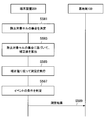
- FIG. 19 is a sequence diagram illustrating a second example of a schematic flow of processing relating to measurement according to a correction value. This example is, for example, processing when the above-described third example (C 3 ) of correction values is used, and the terminal device 200 determines a set of removal target cells.
- the terminal device 200 determines a set of cells to be removed based on the interference removal capability of the user (that is, the terminal device 200) and the measurement result (S581). Furthermore, the terminal device 200 determines a correction value for the user (that is, the terminal device 200) related to interference cancellation based on the set (S583).
- the terminal device 200 measures the cell according to the correction value (S585). And the terminal device 200 determines the conditions of the event which triggers the measurement report about the said cell (S587).
- the terminal device 200 When the above event occurs (that is, when the above condition is satisfied), the terminal device 200 performs a measurement report to the base station 100 (S589). That is, the terminal device 200 reports the measurement result to the base station 100.
- the base station 100 may select a cell for the terminal device 200 based on the measurement result.
- the cell may be a target cell for handover of the terminal device 200. That is, the base station 100 may make a handover decision for the terminal device 200 based on the measurement result.
- the cell may be a secondary cell for the terminal device 200.
- the base station 100 may determine addition or deletion of a secondary cell (secondary component carrier) for the terminal device 200 based on the measurement result.
- FIG. 20 is a sequence diagram illustrating a third example of a schematic flow of processing relating to measurement according to a correction value. This example is, for example, processing when the above-described third example (C 3 ) of correction values is used, and the base station 100 determines a set of cells to be removed.
- the terminal device 200 notifies the base station 100 of the interference removal capability of the user (that is, the terminal device 200) (S601).
- the terminal device 200 performs measurement on the cell (S603). And the terminal device 200 determines the conditions of the event which triggers the measurement report about the said cell (S605).
- the terminal device 200 When the above event occurs (that is, when the above condition is satisfied), the terminal device 200 performs a measurement report to the base station 100 (S607). That is, the terminal device 200 reports the measurement result to the base station 100.
- the base station 100 determines a set of cells to be removed based on the capability and the measurement result (S609). Then, the base station 100 notifies the terminal device 200 of the set (S611). The base station 100 may notify the base station of the neighboring cell of the set, and thus the set may be shared between cells.
- the terminal device 200 determines a correction value for the user (that is, the terminal device 200) related to interference removal based on the set (S613).
- the terminal device 200 measures the cell according to the correction value (S615). And the terminal device 200 determines the conditions of the event which triggers the measurement report about the said cell (S617).
- the terminal device 200 When the above event occurs (that is, when the above condition is satisfied), the terminal device 200 performs a measurement report to the base station 100 (S619). That is, the terminal device 200 reports the measurement result to the base station 100.
- the base station 100 may select a cell for the terminal device 200 based on the measurement result.
- the cell may be a target cell for handover of the terminal device 200. That is, the base station 100 may make a handover decision for the terminal device 200 based on the measurement result.
- the cell may be a secondary cell for the terminal device 200.
- the base station 100 may determine addition or deletion of a secondary cell (secondary component carrier) for the terminal device 200 based on the measurement result.
- the base station 100 may determine a set of cells to be removed.
- another node for example, a core network node may determine a set of cells to be removed.
- FIG. 21 is a sequence diagram illustrating an example of a schematic flow of processing for determining a set of removal target cells. This process is executed by the terminal device 200 and corresponds to step S581 described with reference to FIG.
- the terminal device 200 acquires the RSRP for each cell (S621). And the terminal device 200 selects the M + 1 cell which brings larger RSRP (S623). M is the maximum number of cells to be removed according to the interference removal capability of the terminal device 200.
- the terminal device 200 determines that the selected M + 1 cells other than the measurement target cell are not included. A cell is determined as a set of cells to be removed (S627). Then, the process ends.
- the terminal device 200 brings the smallest RSRP among the selected M + 1 cells. Cells other than the cell are determined as a set of cells to be removed (S629). Then, the process ends.
- the above processing may be executed by the base station 100 instead of the terminal device 200.
- the above process may correspond to step S609 described with reference to FIG.
- the terminal device 200 performs measurement on the cell according to the correction value.
- the base station 100 may perform measurement on the cell according to the correction value.
- the information acquisition unit 151 acquires a correction value for the user (that is, the terminal device 200) related to interference removal, and is used for measurement of communication quality.
- the control part 153 measures the communication quality about the said cell according to the said correction value.
- the terminal device 200 notifies the base station 100 of the interference removal capability of the user (that is, the terminal device 200), and the base station 100 (the processing unit 150), based on the capability, The user's correction value associated with interference cancellation is determined. Then, the base station 100 (information acquisition unit 151) acquires the correction value, and the base station 100 (control unit 153) calculates a new measurement from the correction value and the measurement result reported by the terminal device 200. Calculate the result. For example, in this way, the base station 100 measures the communication quality.
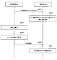
- FIG. 22 is a sequence diagram illustrating a fourth example of a schematic flow of processing related to measurement according to a correction value. This example is processing when the first example (C 1 ) or the second example (C 2 ) of the correction value described above is used, for example.
- the terminal device 200 notifies the base station 100 of the interference removal capability of the user (that is, the terminal device 200) (S641).
- the base station 100 determines a correction value for the user (that is, the terminal device 200) related to interference cancellation based on the capability (S643).
- the terminal device 200 performs measurement on the cell (S645). And the terminal device 200 determines the conditions of the event which triggers the measurement report about the said cell (S647).
- the terminal device 200 When the above event occurs (that is, when the above condition is satisfied), the terminal device 200 performs a measurement report to the base station 100 (S649). That is, the terminal device 200 reports the measurement result to the base station 100.
- the base station 100 performs measurement for the cell according to the correction value (S651). For example, the base station 100 calculates a new measurement result from the correction value and the measurement result.
- the base station 100 may select a cell for the terminal device 200 based on the new measurement result.
- the cell may be a target cell for handover of the terminal device 200. That is, the base station 100 may make a handover decision for the terminal device 200 based on the new measurement result.
- the cell may be a secondary cell for the terminal device 200.
- the base station 100 may determine addition or deletion of a secondary cell (secondary component carrier) for the terminal device 200 based on the new measurement result.
- FIG. 23 is a sequence diagram illustrating a fifth example of a schematic flow of a process related to measurement according to a correction value. This example is, for example, processing when the above-described third example (C 3 ) of correction values is used.
- the terminal device 200 notifies the base station 100 of the interference removal capability of the user (that is, the terminal device 200) (S661).
- the terminal device 200 performs measurement on the cell (S663). And the terminal device 200 determines the conditions of the event which triggers the measurement report about the said cell (S665).
- the terminal device 200 When the event occurs (that is, when the above condition is satisfied), the terminal device 200 performs a measurement report to the base station 100 (S667). That is, the terminal device 200 reports the measurement result to the base station 100.
- the base station 100 determines a set of cells to be removed based on the capability and the measurement result (S669).
- the base station 100 may notify the terminal device 200 and / or the base station of the neighboring cell of the set.
- the base station 100 determines a correction value for the user (that is, the terminal device 200) related to interference cancellation based on the set (S671).
- the base station 100 performs measurement for the cell according to the correction value (S673). For example, the base station 100 calculates a new measurement result from the correction value and the measurement result.
- the base station 100 may select a cell for the terminal device 200 based on the new measurement result.
- the cell may be a target cell for handover of the terminal device 200. That is, the base station 100 may make a handover decision for the terminal device 200 based on the new measurement result.
- the cell may be a secondary cell for the terminal device 200.
- the base station 100 may determine addition or deletion of a secondary cell (secondary component carrier) for the terminal device 200 based on the new measurement result.
- the base station 100 may measure the cell according to the correction value.
- another node for example, a core network node or the like may perform measurement on the cell according to the correction value.
- measurement is performed according to the correction value.
- the correction value is calculated according to whether or not interference cancellation is performed. Therefore, measurement reports, handovers, and / or secondary cell addition / deletion can be performed based on more substantial communication quality.
- Inter-cell interference control (1) Premise concept When measurement or measurement report is performed according to the user parameters (for example, user offset, timer value, or correction value) as described above, inter-cell interference control (ICIC) is taken into account the user parameters. ), Better communication quality can be obtained. In particular, it is considered that better communication quality can be obtained in the case of HetNet.
- the user parameters for example, user offset, timer value, or correction value
- the base station 100 is a base station of a macro cell
- the serving cell of the terminal device 200 is a cell 101 that is a macro cell.
- the same frequency band for example, component carrier
- the terminal device 200 may receive a signal (that is, an interference signal) transmitted by the base station 20 in addition to a desired signal transmitted by the base station 100.
- the base station 100 is a small cell base station, and for example, the serving cell of the terminal device 200 is the cell 101 which is a small cell.
- the same frequency band for example, component carrier
- the terminal device 200 can receive a signal (that is, an interference signal) transmitted by the base station 30 in addition to a desired signal transmitted by the base station 100.
- the transmission power of the macro cell is larger than the transmission power of the small cell. Therefore, it can be said that the interference from the macro cell to the small cell is more serious than the interference from the small cell to the macro cell. This applies not only to users with interference cancellation capabilities, but also to users who do not have interference cancellation capabilities.
- ICIC is required. ICIC is, for example, using separate radio resources (eg, resource blocks, subframes, component carriers, etc.) between cells, or adjusting transmission power between cells.
- the terminal device 200 When the terminal device 200 has interference removal capability, the terminal device 200 can remove a signal having a large received power as interference. Therefore, it may be desirable that the ICIC application policy is different between a user who has the capability of removing interference and a user who does not have the capability of removing interference.
- Interference from neighboring cells may depend on the cell selection method. More specifically, for example, interference from neighboring cells may depend on user offset. For example, when the user offset for the serving cell is large, the serving cell is more easily selected, and the serving cell may be selected even in a slightly worse environment. On the other hand, when the user offset for the serving cell is small, the serving cell is more difficult to be selected, and it is considered that the serving cell is selected in a favorable environment. For this reason, it is considered desirable that the ICIC application policy differs depending on the user offset.
- the base station 100 (information acquisition unit 151) is an offset for a user (terminal device 200) related to interference cancellation and triggers a measurement report.
- the offset (that is, user offset) included in the event condition is acquired.
- the base station 100 (control unit 153) determines whether to perform inter-cell interference control (ICIC) for the user based on the offset.
- the base station 100 determines to perform inter-cell interference control for the user, the base station 100 performs the inter-cell interference control.
- the user offset includes an offset for the serving cell of the user (that is, the terminal device 200) and an offset for a neighboring cell. That is, the base station 100 (the control unit 153) determines whether to perform inter-cell interference control for the user based on the offset of the user's serving cell and the offset of neighboring cells.
- the serving cell may be a primary cell of the user (that is, the terminal device 200).
- the base station 100 (control unit 153) performs inter-cell interference control (ICIC) for the user based further on the interference removal capability of the user (that is, the terminal device 200). Determine.
- ICIC inter-cell interference control
- FIG. 24 is an explanatory diagram for explaining an example of determination in a case where a user's serving cell is a macro cell.
- the serving cell of the user that is, the terminal device 200
- the interference that is, interference from the small cell
- the base station 100 determines that the ICIC is not performed. To do.
- the user offset Oup of the serving cell (for example, the primary cell) may be larger than the user offset Oun of the neighboring cells.
- the reception power of the signal (interference signal) of the neighboring cell is larger than the reception power of the signal (desired signal) of the serving cell. Therefore, for example, when the terminal device 200 has the capability of interference removal, interference removal on the user (ie, terminal device 200) side can be performed.
- hysteresis may be considered as follows.
- C-2 Case where the serving cell is a small cell
- the base station 100 is a small cell base station
- the serving cell of the terminal device 200 is a small cell.
- Cell 101 an example of determination in this case will be described with reference to FIG.
- FIG. 25 is an explanatory diagram for explaining an example of determination in a case where the user's serving cell is a small cell.
- the serving cell when the user (that is, the terminal device 200) serving cell is a small cell, there is a possibility that interference (that is, interference from a macro cell) may be large, and thus ICIC may be necessary.
- the serving cell when the user offset Oup of the serving cell (for example, the primary cell) is larger than the user offset Onp of the neighboring cells, the serving cell may be selected even in a somewhat bad environment. Therefore, in this case, if the terminal device 200 does not have interference removal capability, the base station 100 determines to perform ICIC for the terminal device 200. As a result, for example, ICIC is performed.
- radio resources for example, resource blocks
- transmission power is adjusted between a serving cell and neighboring cells for radio resources allocated to the terminal device 200.
- interference removal on the user (ie, terminal device 200) side can be performed.
- the base station 100 (control unit 153) performs inter-cell interference control for the user based further on the measurement result reported by the user (that is, the terminal device 200). It may be determined.
- the measurement result may be a measurement result of received power.
- the received power may be RSRP or other power.
- the measurement results may include a measurement result for the user serving cell and a measurement result for the neighboring cell. That is, the base station 100 may determine whether to perform inter-cell interference control for the user based further on the measurement result for the serving cell and the measurement result for the neighboring cell.
- the base station 100 determines a cell for the user based on a difference between a measurement result (for example, received power) for the serving cell and a measurement result (for example, received power) for the neighboring cell. It may be determined whether to perform inter-interference control.
- a measurement result for example, received power
- a measurement result for example, received power
- the difference between the received power P s for the serving cell and the received power P n for the neighboring cells (hereinafter referred to as received power difference) is represented as P diff .
- the total offset On , total for the peripheral cells is expressed as follows (note that hysteresis may not be included).
- total offset difference The difference between the total offset Op and total for the serving cell (for example, the primary cell) and the total offset On and total for the neighboring cells (hereinafter referred to as “total offset difference”) is expressed as O diff as follows. It expresses.
- the modification is not limited to such an example.
- the difference between the user offset Oup for the serving cell (for example, the primary cell) and the user offset Oun for the neighboring cells may be used instead of the total offset difference O diff.
- FIG. 26 is an explanatory diagram for describing a first example of determination according to a modification.
- the base station 100 may determine that ICIC for the terminal device 200 is not performed.
- the base station 100 may determine to perform ICIC for the terminal device 200.
- the terminal device 200 that is, the user
- interference cancellation is performed on the terminal device 200 side, and thus the base station 100 determines not to perform ICIC for the terminal device 200. May be.
- FIG. 27 is an explanatory diagram for describing a second example of determination according to a modification.
- no total offset difference is taken into account, only the received power difference is taken into account.
- the base station 100 may determine that ICIC for the terminal device 200 is not performed.
- the base station 100 may determine to perform ICIC for the terminal device 200.
- the terminal device 200 that is, the user
- interference cancellation is performed on the terminal device 200 side, and thus the base station 100 determines not to perform ICIC for the terminal device 200. May be.
- the maximum number of cells from which the terminal device 200 can remove interference can be smaller than the number of neighboring cells from which interference should be removed.
- interference cancellation may be performed for the maximum number of neighboring cells, and ICIC may be performed for the remaining neighboring cells. That is, even when the terminal apparatus 200 has interference removal capability, the base station 100 may determine to perform ICIC for the terminal apparatus 200.
- determination of inter-cell interference control is performed. Thereby, for example, it is possible to suppress interference between the serving cell of the terminal device 200 and the neighboring cells.
- the base station 100 determines to perform ICIC for the terminal device 200.
- the base station 100 performs ICIC for the terminal device 200.
- the base station 100 exchanges information with base stations in neighboring cells as an ICIC operation.
- (A) Providing Information to Neighboring Base Station For example, when the base station 100 determines to perform ICIC for the terminal device 200 (that is, a user), (Hereinafter referred to as “neighboring base station”). For example, the base station 100 requests ICIC from the neighboring base stations, and provides information about the terminal device 200 at the time of this request.
- the information provided to the neighboring base station includes a user ID, interference removal capability (for example, presence / absence or type of interference removal type), a serving cell (ie, cell 101) and the neighboring cell. It includes a difference in received power, a difference in offset between the serving cell (that is, cell 101) and the neighboring cell, a serving cell ID, transmission power in the serving cell, and the like.
- interference removal capability for example, presence / absence or type of interference removal type
- a serving cell ie, cell 101
- It includes a difference in received power, a difference in offset between the serving cell (that is, cell 101) and the neighboring cell, a serving cell ID, transmission power in the serving cell, and the like.
- FIG. 28 is an explanatory diagram for explaining an example of information provided to a neighboring base station for ICIC.
- information provided by the base station 100 to neighboring base stations is shown.
- the base station 100 provides the number of users to be ICIC target and information about each user.
- the information about each user includes a user ID, interference removal capability, reception power difference, offset difference, serving cell ID, and transmission power.
- the neighboring base station determines whether ICIC is possible in response to provision of information from the base station 100 (for example, ICIC request), and responds to the base station 100.
- the neighboring base station provides the base station 100 with information indicating the radio resource to be used and the transmission power for the radio resource.
- ICIC request for example, information from the base station 100
- the neighboring base station provides the base station 100 with information indicating the radio resource to be used and the transmission power for the radio resource.
- FIG. 29 is an explanatory diagram for explaining an example of information provided by a neighboring base station for ICIC.
- information provided by neighboring base stations is shown.
- the neighboring base station provides the number of component carriers and information for each component carrier.
- the information for each component carrier includes a cell ID and information for each subframe.
- the information for each subframe indicates a resource block (for example, resource block ID) used in the neighboring cell and transmission power for the resource block.
- the base station 100 can allocate radio resources to the terminal device 200 while avoiding interference with neighboring cells. That is, ICIC is realized.
- FIG. 30 is a sequence diagram illustrating an example of a schematic process flow relating to inter-cell interference control (ICIC).
- ICIC inter-cell interference control
- the terminal device 200 notifies the base station 100 of the interference removal capability of the user (that is, the terminal device 200) (S681).
- the base station 100 determines an offset (that is, user offset) for the user (that is, the terminal device 200) related to interference cancellation based on the capability (S683). And the base station 100 notifies the said user offset to the terminal device 200 (S685).
- the terminal device 200 performs measurement on the cell (S687). And the terminal device 200 determines the conditions of the event which triggers the measurement report about the said cell according to the said user offset (S689).
- the terminal device 200 When the above event occurs (that is, when the above condition is satisfied), the terminal device 200 performs a measurement report to the base station 100 (S691). That is, the terminal device 200 reports the measurement result to the base station 100.
- the base station 100 determines whether to perform inter-cell interference control (ICIC) for the user (that is, the terminal device 200) based on the user offset (and the measurement result) (S693).
- ICIC inter-cell interference control
- the base station 100 When determining that the ICIC is to be performed, the base station 100 requests the ICIC from the neighboring base station (the neighboring cell base station) (S695).
- the peripheral base station determines whether to perform ICIC in response to a request from the base station 100 (S697), and responds to the base station 100 (S699).
- the base station 100 performs scheduling (S701). That is, the base station 100 allocates radio resources to the terminal device 200 so that interference with the neighboring cells is avoided.
- the base station 100 may be realized as any type of eNB (evolved Node B) such as a macro eNB or a small eNB.
- the small eNB may be an eNB that covers a cell smaller than a macro cell, such as a pico eNB, a micro eNB, or a home (femto) eNB.
- the base station 100 may be realized as another type of base station such as a NodeB or a BTS (Base Transceiver Station).
- Base station 100 may include a main body (also referred to as a base station apparatus) that controls radio communication, and one or more RRHs (Remote Radio Heads) that are arranged at locations different from the main body. Further, various types of terminals described later may operate as the base station 100 by temporarily or semi-permanently executing the base station function. Furthermore, at least some components of the base station 100 may be realized in a base station apparatus or a module for the base station apparatus.
- RRHs Remote Radio Heads
- the terminal device 200 is a smartphone, a tablet PC (Personal Computer), a notebook PC, a portable game terminal, a mobile terminal such as a portable / dongle type mobile router or a digital camera, or an in-vehicle terminal such as a car navigation device. It may be realized as.
- the terminal device 200 may be realized as a terminal (also referred to as an MTC (Machine Type Communication) terminal) that performs M2M (Machine To Machine) communication.
- MTC Machine Type Communication
- M2M Machine To Machine
- at least a part of the components of the terminal device 200 may be realized in a module (for example, an integrated circuit module configured by one die) mounted on these terminals.
- FIG. 31 is a block diagram illustrating a first example of a schematic configuration of an eNB to which the technology according to the present disclosure may be applied.
- the eNB 800 includes one or more antennas 810 and a base station device 820. Each antenna 810 and the base station apparatus 820 can be connected to each other via an RF cable.
- Each of the antennas 810 has a single or a plurality of antenna elements (for example, a plurality of antenna elements constituting a MIMO antenna), and is used for transmission and reception of radio signals by the base station apparatus 820.
- the eNB 800 includes a plurality of antennas 810 as illustrated in FIG. 31, and the plurality of antennas 810 may respectively correspond to a plurality of frequency bands used by the eNB 800, for example.
- FIG. 31 shows an example in which the eNB 800 has a plurality of antennas 810, the eNB 800 may have a single antenna 810.
- the base station apparatus 820 includes a controller 821, a memory 822, a network interface 823, and a wireless communication interface 825.
- the controller 821 may be a CPU or a DSP, for example, and operates various functions of the upper layer of the base station apparatus 820. For example, the controller 821 generates a data packet from the data in the signal processed by the wireless communication interface 825, and transfers the generated packet via the network interface 823. The controller 821 may generate a bundled packet by bundling data from a plurality of baseband processors, and may transfer the generated bundled packet. In addition, the controller 821 is a logic that executes control such as radio resource control, radio bearer control, mobility management, inflow control, or scheduling. May have a typical function. Moreover, the said control may be performed in cooperation with a surrounding eNB or a core network node.
- the memory 822 includes RAM and ROM, and stores programs executed by the controller 821 and various control data (for example, terminal list, transmission power data, scheduling data, and the like).
- the network interface 823 is a communication interface for connecting the base station device 820 to the core network 824.
- the controller 821 may communicate with the core network node or other eNB via the network interface 823.
- the eNB 800 and the core network node or another eNB may be connected to each other by a logical interface (for example, an S1 interface or an X2 interface).
- the network interface 823 may be a wired communication interface or a wireless communication interface for wireless backhaul.
- the network interface 823 may use a frequency band higher than the frequency band used by the wireless communication interface 825 for wireless communication.
- the wireless communication interface 825 supports any cellular communication scheme such as LTE (Long Term Evolution) or LTE-Advanced, and provides a wireless connection to terminals located in the cell of the eNB 800 via the antenna 810.
- the wireless communication interface 825 may typically include a baseband (BB) processor 826, an RF circuit 827, and the like.
- the BB processor 826 may perform, for example, encoding / decoding, modulation / demodulation, and multiplexing / demultiplexing, and each layer (for example, L1, MAC (Medium Access Control), RLC (Radio Link Control), and PDCP).
- Various signal processing of Packet Data Convergence Protocol
- Packet Data Convergence Protocol is executed.
- the BB processor 826 may have some or all of the logical functions described above instead of the controller 821.
- the BB processor 826 may be a module that includes a memory that stores a communication control program, a processor that executes the program, and related circuits. The function of the BB processor 826 may be changed by updating the program. Good.
- the module may be a card or a blade inserted into a slot of the base station apparatus 820, or a chip mounted on the card or the blade.
- the RF circuit 827 may include a mixer, a filter, an amplifier, and the like, and transmits and receives a radio signal via the antenna 810.
- the radio communication interface 825 includes a plurality of BB processors 826 as illustrated in FIG. 31, and the plurality of BB processors 826 may respectively correspond to a plurality of frequency bands used by the eNB 800, for example.
- the wireless communication interface 825 includes a plurality of RF circuits 827 as illustrated in FIG. 31, and the plurality of RF circuits 827 may correspond to, for example, a plurality of antenna elements, respectively.
- FIG. 31 shows an example in which the wireless communication interface 825 includes a plurality of BB processors 826 and a plurality of RF circuits 827.
- the wireless communication interface 825 includes a single BB processor 826 or a single RF circuit 827. But you can.
- the information acquisition unit 151 and the control unit 153 described with reference to FIG. 7 may be implemented in the wireless communication interface 825. Alternatively, at least some of these components may be implemented in the controller 821.
- the eNB 800 includes a module including a part (for example, the BB processor 826) or all of the wireless communication interface 825 and / or the controller 821, and the information acquisition unit 151 and the control unit 153 are mounted in the module. Also good.
- the module stores a program for causing the processor to function as the information acquisition unit 151 and the control unit 153 (in other words, a program for causing the processor to execute operations of the information acquisition unit 151 and the control unit 153).
- the program may be executed.
- a program for causing a processor to function as the information acquisition unit 151 and the control unit 153 is installed in the eNB 800, and the wireless communication interface 825 (for example, the BB processor 826) and / or the controller 821 executes the program.
- the eNB 800, the base station apparatus 820, or the module may be provided as an apparatus including the information acquisition unit 151 and the control unit 153, and a program for causing the processor to function as the information acquisition unit 151 and the control unit 153 is provided. May be provided.
- a readable recording medium in which the program is recorded may be provided.
- the wireless communication unit 120 described with reference to FIG. 7 may be implemented in the wireless communication interface 825 (for example, the RF circuit 827). Further, the antenna unit 110 may be mounted on the antenna 810.
- the network communication unit 130 may be implemented in the controller 821 and / or the network interface 823.
- FIG. 32 is a block diagram illustrating a second example of a schematic configuration of an eNB to which the technology according to the present disclosure may be applied.
- the eNB 830 includes one or more antennas 840, a base station apparatus 850, and an RRH 860. Each antenna 840 and RRH 860 may be connected to each other via an RF cable. Base station apparatus 850 and RRH 860 can be connected to each other via a high-speed line such as an optical fiber cable.
- Each of the antennas 840 has a single or a plurality of antenna elements (for example, a plurality of antenna elements constituting a MIMO antenna), and is used for transmission / reception of radio signals by the RRH 860.
- the eNB 830 includes a plurality of antennas 840 as illustrated in FIG. 32, and the plurality of antennas 840 may respectively correspond to a plurality of frequency bands used by the eNB 830, for example. 32 shows an example in which the eNB 830 has a plurality of antennas 840, but the eNB 830 may have a single antenna 840.
- the base station device 850 includes a controller 851, a memory 852, a network interface 853, a wireless communication interface 855, and a connection interface 857.
- the controller 851, the memory 852, and the network interface 853 are the same as the controller 821, the memory 822, and the network interface 823 described with reference to FIG.
- the wireless communication interface 855 supports a cellular communication method such as LTE or LTE-Advanced, and provides a wireless connection to a terminal located in a sector corresponding to the RRH 860 via the RRH 860 and the antenna 840.
- the wireless communication interface 855 may typically include a BB processor 856 and the like.
- the BB processor 856 is the same as the BB processor 826 described with reference to FIG. 31 except that the BB processor 856 is connected to the RF circuit 864 of the RRH 860 via the connection interface 857.
- the wireless communication interface 855 includes a plurality of BB processors 856 as illustrated in FIG.
- the wireless communication interface 855 includes a plurality of BB processors 856
- the wireless communication interface 855 may include a single BB processor 856.
- connection interface 857 is an interface for connecting the base station device 850 (wireless communication interface 855) to the RRH 860.
- the connection interface 857 may be a communication module for communication on the high-speed line that connects the base station apparatus 850 (wireless communication interface 855) and the RRH 860.
- the RRH 860 includes a connection interface 861 and a wireless communication interface 863.
- connection interface 861 is an interface for connecting the RRH 860 (wireless communication interface 863) to the base station device 850.
- the connection interface 861 may be a communication module for communication on the high-speed line.
- the wireless communication interface 863 transmits and receives wireless signals via the antenna 840.
- the wireless communication interface 863 may typically include an RF circuit 864 and the like.
- the RF circuit 864 may include a mixer, a filter, an amplifier, and the like, and transmits and receives wireless signals via the antenna 840.
- the wireless communication interface 863 includes a plurality of RF circuits 864 as shown in FIG. 32, and the plurality of RF circuits 864 may correspond to, for example, a plurality of antenna elements, respectively.
- 32 shows an example in which the wireless communication interface 863 includes a plurality of RF circuits 864, the wireless communication interface 863 may include a single RF circuit 864.
- the information acquisition unit 151 and the control unit 153 described with reference to FIG. 7 may be implemented in the wireless communication interface 855 and / or the wireless communication interface 863.
- the eNB 830 illustrated in FIG. Alternatively, at least some of these components may be implemented in the controller 851.
- the eNB 830 includes a part of the wireless communication interface 855 (for example, the BB processor 856) or / and a module including the controller 851, and the information acquisition unit 151 and the control unit 153 are mounted in the module. Also good.
- the module stores a program for causing the processor to function as the information acquisition unit 151 and the control unit 153 (in other words, a program for causing the processor to execute operations of the information acquisition unit 151 and the control unit 153).
- the program may be executed.
- a program for causing a processor to function as the information acquisition unit 151 and the control unit 153 is installed in the eNB 830, and the wireless communication interface 855 (for example, the BB processor 856) and / or the controller 851 execute the program. Also good.
- the eNB 830, the base station apparatus 850, or the module may be provided as an apparatus including the information acquisition unit 151 and the control unit 153, and a program for causing the processor to function as the information acquisition unit 151 and the control unit 153 is provided. May be provided.
- a readable recording medium in which the program is recorded may be provided.
- the wireless communication unit 120 described with reference to FIG. 7 may be implemented in the wireless communication interface 863 (for example, the RF circuit 864).
- the antenna unit 110 may be mounted on the antenna 840.
- the network communication unit 130 may be implemented in the controller 851 and / or the network interface 853.
- FIG. 33 is a block diagram illustrating an example of a schematic configuration of a smartphone 900 to which the technology according to the present disclosure may be applied.
- the smartphone 900 includes a processor 901, a memory 902, a storage 903, an external connection interface 904, a camera 906, a sensor 907, a microphone 908, an input device 909, a display device 910, a speaker 911, a wireless communication interface 912, one or more antenna switches 915.
- One or more antennas 916, a bus 917, a battery 918 and an auxiliary controller 919 are provided.
- the processor 901 may be, for example, a CPU or a SoC (System on Chip), and controls the functions of the application layer and other layers of the smartphone 900.
- the memory 902 includes a RAM and a ROM, and stores programs executed by the processor 901 and data.
- the storage 903 can include a storage medium such as a semiconductor memory or a hard disk.
- the external connection interface 904 is an interface for connecting an external device such as a memory card or a USB (Universal Serial Bus) device to the smartphone 900.
- the camera 906 includes, for example, an image sensor such as a CCD (Charge Coupled Device) or a CMOS (Complementary Metal Oxide Semiconductor), and generates a captured image.
- the sensor 907 may include a sensor group such as a positioning sensor, a gyro sensor, a geomagnetic sensor, and an acceleration sensor.
- the microphone 908 converts sound input to the smartphone 900 into an audio signal.
- the input device 909 includes, for example, a touch sensor that detects a touch on the screen of the display device 910, a keypad, a keyboard, a button, or a switch, and receives an operation or information input from a user.
- the display device 910 has a screen such as a liquid crystal display (LCD) or an organic light emitting diode (OLED) display, and displays an output image of the smartphone 900.
- the speaker 911 converts an audio signal output from the smartphone 900 into audio.
- the wireless communication interface 912 supports any cellular communication method such as LTE or LTE-Advanced, and performs wireless communication.
- the wireless communication interface 912 may typically include a BB processor 913, an RF circuit 914, and the like.
- the BB processor 913 may perform, for example, encoding / decoding, modulation / demodulation, and multiplexing / demultiplexing, and performs various signal processing for wireless communication.
- the RF circuit 914 may include a mixer, a filter, an amplifier, and the like, and transmits and receives radio signals via the antenna 916.
- the wireless communication interface 912 may be a one-chip module in which the BB processor 913 and the RF circuit 914 are integrated.
- the wireless communication interface 912 may include a plurality of BB processors 913 and a plurality of RF circuits 914 as illustrated in FIG.
- FIG. 33 shows an example in which the wireless communication interface 912 includes a plurality of BB processors 913 and a plurality of RF circuits 914.
- the wireless communication interface 912 includes a single BB processor 913 or a single RF circuit 914. But you can.
- the wireless communication interface 912 may support other types of wireless communication methods such as a short-range wireless communication method, a proximity wireless communication method, or a wireless LAN (Local Area Network) method in addition to the cellular communication method.
- a BB processor 913 and an RF circuit 914 for each wireless communication method may be included.
- Each of the antenna switches 915 switches the connection destination of the antenna 916 among a plurality of circuits (for example, circuits for different wireless communication systems) included in the wireless communication interface 912.
- Each of the antennas 916 includes a single or a plurality of antenna elements (for example, a plurality of antenna elements constituting a MIMO antenna), and is used for transmission / reception of a radio signal by the radio communication interface 912.
- the smartphone 900 may include a plurality of antennas 916 as illustrated in FIG. Note that although FIG. 33 illustrates an example in which the smartphone 900 includes a plurality of antennas 916, the smartphone 900 may include a single antenna 916.
- the smartphone 900 may include an antenna 916 for each wireless communication method.
- the antenna switch 915 may be omitted from the configuration of the smartphone 900.
- the bus 917 connects the processor 901, memory 902, storage 903, external connection interface 904, camera 906, sensor 907, microphone 908, input device 909, display device 910, speaker 911, wireless communication interface 912, and auxiliary controller 919 to each other.
- the battery 918 supplies electric power to each block of the smartphone 900 shown in FIG. 33 through a power supply line partially shown by a broken line in the drawing.
- the auxiliary controller 919 operates the minimum necessary functions of the smartphone 900 in the sleep mode.
- the information acquisition unit 241 and the control unit 243 described with reference to FIG. 8 may be implemented in the wireless communication interface 912.
- the smartphone 900 illustrated in FIG. Alternatively, at least some of these components may be implemented in the processor 901 or the auxiliary controller 919.
- the smartphone 900 includes a module including a part (for example, the BB processor 913) or all of the wireless communication interface 912, the processor 901, and / or the auxiliary controller 919, and the information acquisition unit 241 and the control unit in the module. 243 may be implemented.
- the module stores a program for causing the processor to function as the information acquisition unit 241 and the control unit 243 (in other words, a program for causing the processor to execute operations of the information acquisition unit 241 and the control unit 243).
- the program may be executed.
- a program for causing a processor to function as the information acquisition unit 241 and the control unit 243 is installed in the smartphone 900, and the wireless communication interface 912 (for example, the BB processor 913), the processor 901, and / or the auxiliary controller 919 is installed.
- the program may be executed.
- the smartphone 900 or the module may be provided as an apparatus including the information acquisition unit 241 and the control unit 243, or a program for causing the processor to function as the information acquisition unit 241 and the control unit 243 may be provided. Good.
- a readable recording medium in which the program is recorded may be provided.
- the wireless communication unit 220 described with reference to FIG. 8 may be implemented in the wireless communication interface 912 (for example, the RF circuit 914).
- the antenna unit 210 may be mounted on the antenna 916.
- FIG. 34 is a block diagram illustrating an example of a schematic configuration of a car navigation device 920 to which the technology according to the present disclosure can be applied.
- the car navigation device 920 includes a processor 921, a memory 922, a GPS (Global Positioning System) module 924, a sensor 925, a data interface 926, a content player 927, a storage medium interface 928, an input device 929, a display device 930, a speaker 931, and wireless communication.
- the interface 933 includes one or more antenna switches 936, one or more antennas 937, and a battery 938.
- the processor 921 may be a CPU or SoC, for example, and controls the navigation function and other functions of the car navigation device 920.
- the memory 922 includes RAM and ROM, and stores programs and data executed by the processor 921.
- the GPS module 924 measures the position (for example, latitude, longitude, and altitude) of the car navigation device 920 using GPS signals received from GPS satellites.
- the sensor 925 may include a sensor group such as a gyro sensor, a geomagnetic sensor, and an atmospheric pressure sensor.
- the data interface 926 is connected to the in-vehicle network 941 through a terminal (not shown), for example, and acquires data generated on the vehicle side such as vehicle speed data.
- the content player 927 reproduces content stored in a storage medium (for example, CD or DVD) inserted into the storage medium interface 928.
- the input device 929 includes, for example, a touch sensor, a button, or a switch that detects a touch on the screen of the display device 930, and receives an operation or information input from the user.
- the display device 930 has a screen such as an LCD or an OLED display, and displays a navigation function or an image of content to be reproduced.
- the speaker 931 outputs the navigation function or the audio of the content to be played back.
- the wireless communication interface 933 supports any cellular communication method such as LTE or LTE-Advanced, and performs wireless communication.
- the wireless communication interface 933 may typically include a BB processor 934, an RF circuit 935, and the like.
- the BB processor 934 may perform, for example, encoding / decoding, modulation / demodulation, and multiplexing / demultiplexing, and performs various signal processing for wireless communication.
- the RF circuit 935 may include a mixer, a filter, an amplifier, and the like, and transmits and receives a radio signal via the antenna 937.
- the wireless communication interface 933 may be a one-chip module in which the BB processor 934 and the RF circuit 935 are integrated.
- the wireless communication interface 933 may include a plurality of BB processors 934 and a plurality of RF circuits 935 as shown in FIG. 34 shows an example in which the wireless communication interface 933 includes a plurality of BB processors 934 and a plurality of RF circuits 935, the wireless communication interface 933 includes a single BB processor 934 or a single RF circuit 935. But you can.
- the wireless communication interface 933 may support other types of wireless communication methods such as a short-range wireless communication method, a proximity wireless communication method, or a wireless LAN method in addition to the cellular communication method.
- a BB processor 934 and an RF circuit 935 may be included for each communication method.
- Each of the antenna switches 936 switches the connection destination of the antenna 937 among a plurality of circuits included in the wireless communication interface 933 (for example, circuits for different wireless communication systems).
- Each of the antennas 937 has a single or a plurality of antenna elements (for example, a plurality of antenna elements constituting a MIMO antenna), and is used for transmission / reception of a radio signal by the radio communication interface 933.
- the car navigation device 920 may include a plurality of antennas 937 as shown in FIG. FIG. 34 shows an example in which the car navigation device 920 includes a plurality of antennas 937, but the car navigation device 920 may include a single antenna 937.
- the car navigation device 920 may include an antenna 937 for each wireless communication method.
- the antenna switch 936 may be omitted from the configuration of the car navigation device 920.
- the battery 938 supplies power to each block of the car navigation device 920 shown in FIG. 34 via a power supply line partially shown by a broken line in the drawing. Further, the battery 938 stores electric power supplied from the vehicle side.
- the information acquisition unit 241 and the control unit 243 described with reference to FIG. 8 may be implemented in the wireless communication interface 933.
- the car navigation apparatus 920 illustrated in FIG. Alternatively, at least some of these components may be implemented in the processor 921.
- the car navigation device 920 includes a module including a part (for example, the BB processor 934) or all of the wireless communication interface 933 and / or the processor 921, and the information acquisition unit 241 and the control unit 243 are mounted in the module. May be.
- the module stores a program for causing the processor to function as the information acquisition unit 241 and the control unit 243 (in other words, a program for causing the processor to execute operations of the information acquisition unit 241 and the control unit 243).
- the program may be executed.
- a program for causing a processor to function as the information acquisition unit 241 and the control unit 243 is installed in the car navigation device 920, and the wireless communication interface 933 (for example, the BB processor 934) and / or the processor 921 executes the program. May be executed.
- the car navigation device 920 or the module may be provided as a device including the information acquisition unit 241 and the control unit 243, and a program for causing the processor to function as the information acquisition unit 241 and the control unit 243 is provided. May be.
- a readable recording medium in which the program is recorded may be provided.
- the wireless communication unit 220 described with reference to FIG. 8 may be implemented in the wireless communication interface 933 (for example, the RF circuit 935).
- the antenna unit 210 may be mounted on the antenna 937.
- an in-vehicle system (or vehicle) 940 including one or more blocks of the car navigation device 920 described above, an in-vehicle network 941, and a vehicle side module 942. That is, an in-vehicle system (or vehicle) 940 may be provided as a device including the information acquisition unit 241 and the control unit 243.
- the vehicle-side module 942 generates vehicle-side data such as vehicle speed, engine speed, or failure information, and outputs the generated data to the in-vehicle network 941.
- the terminal device 200 includes an information acquisition unit 241 that acquires parameters for a user related to interference cancellation, and a control unit that performs measurement or measurement report on a cell according to the parameters. 243.
- the base station 100 performs the measurement or the measurement report on the cell according to the information acquisition unit 151 that acquires the parameter for the user related to the interference cancellation, and the parameter.
- processing steps in the processing of the present specification may not necessarily be executed in time series in the order described in the flowchart or the sequence diagram.
- processing steps in the processing may be executed in an order different from the order described as a flowchart or a sequence diagram, or may be executed in parallel.
- a processor for example, a CPU, a DSP, or the like included in a device of the present specification (for example, a base station, a base station device, a module for a base station device, or a terminal device or a module for a terminal device) is provided. It is also possible to create a computer program (in other words, a computer program for causing the processor to execute the operation of the component of the device) to function as a component of the device (for example, an information acquisition unit and a control unit). . Moreover, a recording medium on which the computer program is recorded may be provided.
- An apparatus for example, a base station, a base station apparatus, a module for a base station apparatus, a terminal apparatus, or a device including a memory for storing the computer program and one or more processors capable of executing the computer program
- a module for a terminal device may also be provided.
- a method including the operation of the components of the device for example, an information acquisition unit and a communication control unit is also included in the technology according to the present disclosure.
- An acquisition unit for acquiring parameters for a user related to interference cancellation; A control unit for measuring or reporting a cell according to the parameters; A device comprising: (2) The apparatus according to (1), wherein the parameter is a value corresponding to an interference removal capability of the user. (3) The apparatus according to (2), wherein the parameter is larger when the user has interference removal capability and smaller when the user does not have interference removal capability. (4) The apparatus according to any one of (1) to (3), wherein the parameter is a value corresponding to the cell or the type of the cell. (5) The apparatus according to (4), wherein the parameter is larger when the cell is a small cell and smaller when the cell is a macro cell.
- the parameter is an offset for the user related to interference cancellation and included in a condition of an event that triggers a measurement report; The control unit performs the measurement report for the cell according to the offset.
- the apparatus according to (6), wherein the offset is a value added to a measurement result under the condition.
- the parameter is a timer value for the user related to interference cancellation, the timer value set to a timer used for measurement reporting; The control unit performs the measurement report for the cell according to the timer value.
- the timer is a timer that starts when an event condition that triggers a measurement report is satisfied, The control unit performs the measurement report for the cell after the timer expires.
- the parameter is a correction value for the user related to interference cancellation, the correction value used for measuring communication quality;
- the control unit performs the measurement for the cell according to the correction value,
- the measurement for the cell is a measurement of communication quality for the cell;
- the apparatus according to any one of (1) to (5).
- the apparatus according to (13), wherein the communication quality is SNR (Signal to Noise Ratio), SINR (Signal to Interference-plus-Noise Ratio), or RSRQ (Reference Signal Received Quality).
- the correction value is a correction value for subtracting an interference component from communication quality in accordance with the interference removal capability of the user.
- the correction value is any one of the above (13) to (15), which is a value calculated from a measurement result of one or more other cells selected according to the interference removal capability of the user.
- a device comprising: (19)
- the parameter is an offset for the user related to interference cancellation and included in a condition of an event that triggers a measurement report;
- the control unit determines whether to perform inter-cell interference control for the user based on the offset;
- the said control part is an apparatus as described in said (19) or (20) which determines whether the said inter-cell interference control for the said user is performed further based on the capability of the said user's interference removal.
- the control unit according to any one of (19) to (21), wherein the control unit determines whether to perform the inter-cell interference control for the user based further on a measurement result reported by the user. Equipment.
Landscapes
- Engineering & Computer Science (AREA)
- Computer Networks & Wireless Communication (AREA)
- Signal Processing (AREA)
- Mobile Radio Communication Systems (AREA)
- Transmitters (AREA)
Abstract
【課題】干渉除去を考慮した測定又は測定報告を行うことを可能にする。 【解決手段】干渉除去に関連する、ユーザのためのパラメータを取得する取得部と、上記パラメータに従って、セルについての測定又は測定報告を行う制御部と、を備える装置が提供される。
Description
本開示は、装置に関する。
LTE(Long Term Evolution)/LTE-A(Advanced)に続く第5世代(5G)移動体通信システムの無線アクセス技術(Radio Access Technology:RAT)として、非直交多元接続(Non-Orthogonal Multiple Access)が注目されている。LTEにおいて採用されているOFDMA(Orthogonal Frequency-Division Multiple Access)及びSC-FDMA(Single-Carrier Frequency-Division Multiple Access)では、無線リソース(例えば、リソースブロック)は、重複なくユーザに割り当てられる。これらの方式は、直交多元接続と呼ばれ得る。一方、非直交多元接続では、無線リソースは、重複してユーザに割り当てられる。非直交多元接続では、ユーザの信号が互いに干渉するが、受信側における高精度な復号処理によりユーザごとの信号が取り出される。非直交多元接続は、理論的には、直交多元接続よりも高いセル通信容量を実現することが可能である。
非直交多元接続に分類される無線アクセス技術の1つとして、SPC(Superposition Coding)多重化/多元接続が挙げられる。SPCは、異なる電力が割り当てられた信号を同一の無線リソース上で多重化する方式である。受信側では、同一の無線リソース上で多重化された信号の受信/復号のために、干渉除去(Interference Cancellation)及び/又は繰返し検出などの受信処理が行われる。
例えば、特許文献1及び2には、SPC又はSPCに準ずる技術として、適切な復調/復号を可能にする振幅(又は電力)の設定の手法が開示されている。また、例えば、特許文献3には、多重化された信号を受信するためのSIC(Successive Interference Cancellation)の高度化の手法が開示されている。
非直行多重化/多元接続が用いられるか、又は直交多重化/多元接続が用いられるかによらず、ユーザ側で干渉除去が行われる場合には、干渉除去が行われない場合と比べて、より良好な通信品質が得られる。そのため、ユーザ側で干渉除去が行われるか否かによって、当該ユーザにとって利用可能なセルも異なり得る。しかし、既存の仕組みでは、セルの選択(例えば、ハンドオーバ又はセカンダリセルの追加などのためのセルの選択)につながる測定(measurements)又は測定報告(measurement reporting)は、ユーザ側での干渉除去の有無にかかわらず行われる。
そこで、干渉除去を考慮した測定又は測定報告を行うことを可能にする仕組みが提供されることが望ましい。
本開示によれば、干渉除去に関連する、ユーザのためのパラメータを取得する取得部と、上記パラメータに従って、セルについての測定又は測定報告を行う制御部と、を備える装置が提供される。
また、本開示によれば、干渉除去に関連する、ユーザのためのパラメータを取得する取得部と、上記パラメータに従ってセルについての測定又は測定報告を行う上記ユーザに、上記パラメータを通知する制御部と、を備える装置が提供される。
以上説明したように本開示によれば、干渉除去を考慮した測定報告を行うことが可能になる。なお、上記の効果は必ずしも限定的なものではなく、上記効果とともに、又は上記効果に代えて、本明細書に示されたいずれかの効果、又は本明細書から把握され得る他の効果が奏されてもよい。
以下に添付の図面を参照しながら、本開示の好適な実施の形態について詳細に説明する。なお、本明細書及び図面において、実質的に同一の機能構成を有する構成要素については、同一の符号を付することにより重複説明を省略する。
なお、説明は以下の順序で行うものとする。
1.SPC
2.システムの概略的な構成
3.各装置の構成
3.1.基地局の構成
3.2.端末装置の構成
4.処理の流れ
4.1.ユーザパラメータに従った測定/測定報告
4.2.セル間干渉制御
5.応用例
5.1.基地局に関する応用例
5.2.端末装置に関する応用例
6.まとめ
1.SPC
2.システムの概略的な構成
3.各装置の構成
3.1.基地局の構成
3.2.端末装置の構成
4.処理の流れ
4.1.ユーザパラメータに従った測定/測定報告
4.2.セル間干渉制御
5.応用例
5.1.基地局に関する応用例
5.2.端末装置に関する応用例
6.まとめ
<<1.SPC>>
図1~図3を参照して、SPCの処理及び信号を説明する。
図1~図3を参照して、SPCの処理及び信号を説明する。
(1)送信装置及び受信装置における処理
まず、送信装置及び受信装置における処理を説明する。
まず、送信装置及び受信装置における処理を説明する。
(a)送信装置における処理
図1及び図2は、SPCをサポートする送信装置における処理の一例を説明するための説明図である。図1を参照すると、例えば、ユーザA、ユーザB及びユーザCの各々のビットストリーム(例えば、トランスポートブロック)が処理される。これらのビットストリームの各々について、いくつかの処理(例えば、図2に示されるような)CRC(Cyclic Redundancy Check)符号化、FEC(Forward Error Correction)符号化、レートマッチング及びスクランブリング/インターリービング)が行われ、その後変調が行われる。そして、レイヤマッピング、電力割当て、プリコーディング、SPC多重、リソースエレメントマッピング、IDFT(Inverse Discrete Fourier Transform)/IFFT(Inverse Fast Fourier Transform)、CP(Cyclic Prefix)挿入、並びに、デジタルからアナログ及びRF(Radio Frequency)への変換などが行われる。
図1及び図2は、SPCをサポートする送信装置における処理の一例を説明するための説明図である。図1を参照すると、例えば、ユーザA、ユーザB及びユーザCの各々のビットストリーム(例えば、トランスポートブロック)が処理される。これらのビットストリームの各々について、いくつかの処理(例えば、図2に示されるような)CRC(Cyclic Redundancy Check)符号化、FEC(Forward Error Correction)符号化、レートマッチング及びスクランブリング/インターリービング)が行われ、その後変調が行われる。そして、レイヤマッピング、電力割当て、プリコーディング、SPC多重、リソースエレメントマッピング、IDFT(Inverse Discrete Fourier Transform)/IFFT(Inverse Fast Fourier Transform)、CP(Cyclic Prefix)挿入、並びに、デジタルからアナログ及びRF(Radio Frequency)への変換などが行われる。
とりわけ、電力割当てにおいて、ユーザA、ユーザB及びユーザCの各々の信号に電力が割り当てられ、SPC多重化において、ユーザA、ユーザB及びユーザCの信号が多重化される。
(b)受信装置における処理
図3は、干渉除去を行う受信装置における処理の一例を説明するための説明図である。図3を参照すると、例えば、RF及びアナログからデジタルへの変換、CP除去(removal)、DFT(Discrete Fourier Transform)/FFT(Fast Fourier Transform)、並びに、ジョイント干渉除去、等化及び復号などが行われる。その結果、ユーザA、ユーザB及びユーザCの各々のビットストリーム(例えば、トランスポートブロック)が得られる。
図3は、干渉除去を行う受信装置における処理の一例を説明するための説明図である。図3を参照すると、例えば、RF及びアナログからデジタルへの変換、CP除去(removal)、DFT(Discrete Fourier Transform)/FFT(Fast Fourier Transform)、並びに、ジョイント干渉除去、等化及び復号などが行われる。その結果、ユーザA、ユーザB及びユーザCの各々のビットストリーム(例えば、トランスポートブロック)が得られる。
(2)送信信号及び受信信号
次に、SPCが採用される場合のダウンリンクの送信信号及び受信信号を説明する。ここでは、HetNet(Heterogeneous Network)又はSCE(Small Cell Enhancement)などのマルチセルシステムを想定する。
次に、SPCが採用される場合のダウンリンクの送信信号及び受信信号を説明する。ここでは、HetNet(Heterogeneous Network)又はSCE(Small Cell Enhancement)などのマルチセルシステムを想定する。
対象のユーザuが接続するセルのインデックスをiで表し、当該セルに対応する基地局の送信アンテナの数をNTX,iで表す。当該送信アンテナの各々は、送信アンテナポートとも呼ばれ得る。セルiからユーザuへの送信信号は、以下のようにベクトル形式で表されることが可能である。

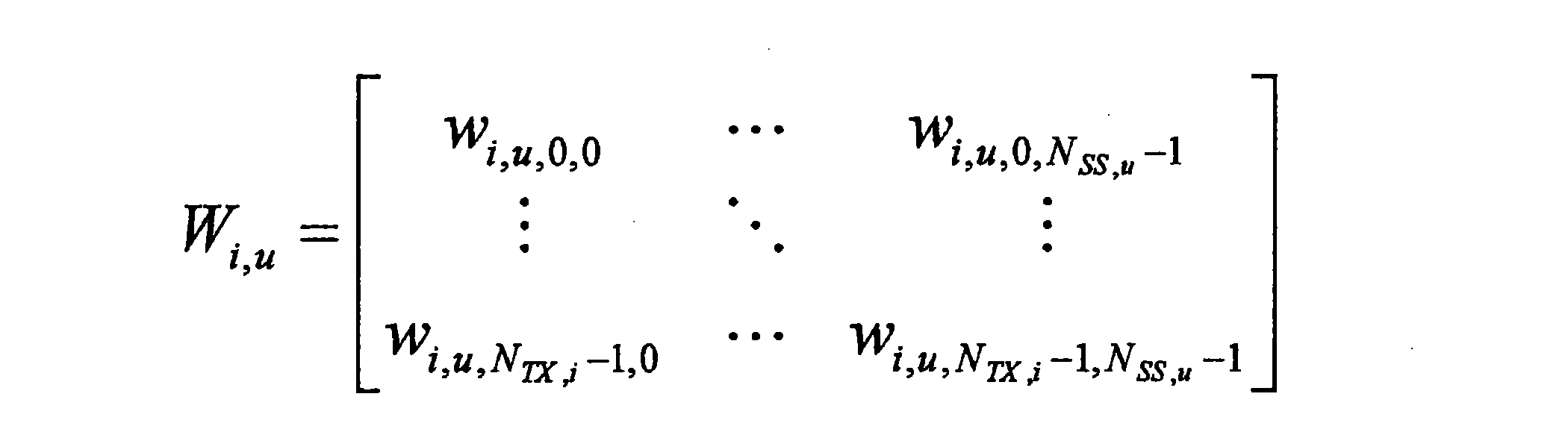

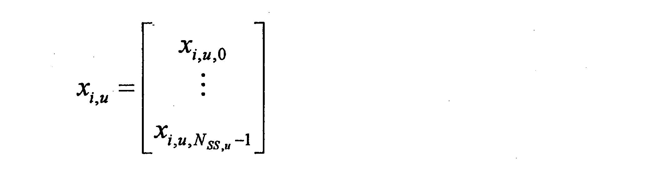
上述した式において、NSS,uは、ユーザuについての空間送信ストリーム数である。基本的には、NSS,uは、NTX,i以下の正の整数である。ベクトルxi,uは、ユーザuへの空間ストリーム信号である。このベクトルの各要素は、基本的には、PSK(Phase Shift Keying)又はQAM(Quadrature Amplitude Modulation)などのデジタル変調シンボルに相当する。行列Wi,uは、ユーザuについてのプリコーディング行列である。この行列内の要素は、基本的には複素数であるが、実数であってもよい。
行列Pi,uは、セルiにおけるユーザuのための電力割当て係数行列である。この行列では、各要素が正の実数であることが望ましい。なお、この行列は、以下のような対角行列(即ち、対角成分以外が0である行列)であってもよい。

空間ストリームについて適応的な電力割当てが行われない場合には、行列Pi,uの代わりに、スカラ値Pi,uが用いられてもよい。
セルiには、ユーザuのみではなく他のユーザvも存在し、他のユーザvの信号si,vも、同一の無線リソースで送信される。これらの信号は、SPCにより多重化される。多重化後のセルiからの信号siは、以下のように表される。

上述した式において、Uiは、セルiにおいて多重化されるユーザの集合である。ユーザuのサービングセル以外のセルj(ユーザuにとっての干渉源となるセル)でも、同様に送信信号sjが生成される。ユーザ側では、このような信号が干渉として受信される。ユーザuの受信信号ruは、以下のように表されることが可能である。
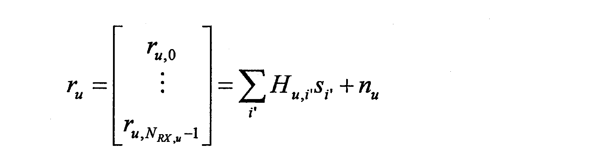
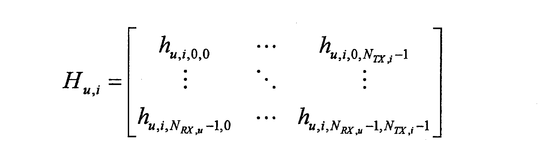
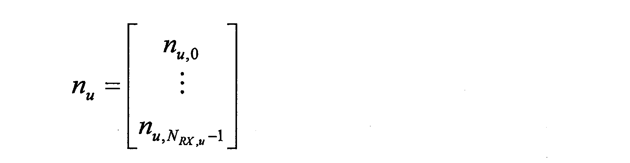
上述した式において、行列Hu,iは、セルi及びユーザuについてのチャネル応答行列である。行列Hu,iの各要素は、基本的には複素数である。ベクトルnuは、ユーザuの受信信号ruに含まれる雑音である。例えば、当該雑音は、熱雑音、及び他のシステムからの干渉などを含む。雑音の平均電力は、以下のように表される。

受信信号ruは、以下のように、所望信号と他の信号とにより表されることも可能である。

上述した式において、右辺の第1項は、ユーザuの所望信号、第2項は、ユーザuのサービングセルi内の干渉(セル内干渉(intra-cell interference)、又は、マルチユーザ干渉若しくはマルチアクセス干渉などと呼ばれる)、第3項は、セルi以外のセルからの干渉(セル間干渉(inter-cell interference)と呼ばれる)である。
なお、直交多元接続(例えば、OFDMA又はSC-FDMA)などが採用される場合には、受信信号は、以下のように表されることが可能である。

直交多元接続では、セル内干渉がなく、また、他のセルjにおいても他のユーザvの信号が同一の無線リソースにおいて多重化されない。
<<2.システムの概略的な構成>>
続いて、図4~図6を参照して、本開示の実施形態に係るシステム1の概略的な構成を説明する。図4は、本開示の実施形態に係るシステム1の概略的な構成の一例を示す説明図である。図4を参照すると、システム1は、基地局100及び端末装置200を含む。ここでは、端末装置200は、ユーザとも呼ばれる。当該ユーザは、ユーザ機器(User Equipment:UE)とも呼ばれ得る。ここでのUEは、LTE又はLTE-AにおけるUEであってもよく、より一般的に通信機器を意味してもよい。
続いて、図4~図6を参照して、本開示の実施形態に係るシステム1の概略的な構成を説明する。図4は、本開示の実施形態に係るシステム1の概略的な構成の一例を示す説明図である。図4を参照すると、システム1は、基地局100及び端末装置200を含む。ここでは、端末装置200は、ユーザとも呼ばれる。当該ユーザは、ユーザ機器(User Equipment:UE)とも呼ばれ得る。ここでのUEは、LTE又はLTE-AにおけるUEであってもよく、より一般的に通信機器を意味してもよい。
(1)基地局100
基地局100は、セルラーシステム(又は移動体通信システム)の基地局である。基地局100は、基地局100のセル101内に位置する端末装置(例えば、端末装置200)との無線通信を行う。例えば、基地局100は、端末装置へのダウンリンク信号を送信し、端末装置からのアップリンク信号を受信する。
基地局100は、セルラーシステム(又は移動体通信システム)の基地局である。基地局100は、基地局100のセル101内に位置する端末装置(例えば、端末装置200)との無線通信を行う。例えば、基地局100は、端末装置へのダウンリンク信号を送信し、端末装置からのアップリンク信号を受信する。
(2)端末装置200
端末装置200は、セルラーシステム(又は移動体通信システム)において通信可能である。端末装置200は、セルラーシステムの基地局(例えば、基地局100)との無線通信を行う。例えば、端末装置200は、基地局からのダウンリンク信号を受信し、基地局へのアップリンク信号を送信する。
端末装置200は、セルラーシステム(又は移動体通信システム)において通信可能である。端末装置200は、セルラーシステムの基地局(例えば、基地局100)との無線通信を行う。例えば、端末装置200は、基地局からのダウンリンク信号を受信し、基地局へのアップリンク信号を送信する。
(3)HetNet
(a)マクロセルのケース
例えば、基地局100は、マクロセルの基地局である。即ち、セル101は、マクロセルである。以下、この点について図5を参照して、具体例を説明する。
(a)マクロセルのケース
例えば、基地局100は、マクロセルの基地局である。即ち、セル101は、マクロセルである。以下、この点について図5を参照して、具体例を説明する。
図5は、基地局100がマクロセルの基地局であるケースを説明するための説明図である。図5を参照すると、基地局100及び端末装置200が示されている。この例では、基地局100は、マクロセルの基地局であり、セル101は、スモールセル21と重なるマクロセルである。例えば、端末装置200は、スモールセル21内に位置する場合に、スモールセル21の基地局20との無線通信を行うことが可能である。
(b)スモールセルのケース
基地局100は、スモールセルの基地局であってもよい。即ち、セル101は、スモールセルであってもよい。以下、この点について図6を参照して、具体例を説明する。
基地局100は、スモールセルの基地局であってもよい。即ち、セル101は、スモールセルであってもよい。以下、この点について図6を参照して、具体例を説明する。
図6は、基地局100がスモールセルの基地局であるケースを説明するための説明図である。図6を参照すると、基地局100及び端末装置200が示されている。この例では、基地局100は、スモールセルの基地局であり、セル101は、マクロセル31と重なるスモールセルである。例えば、端末装置200は、マクロセル31内に位置する場合に、マクロセル31の基地局30との無線通信を行うことが可能である。
(c)周波数帯域
例えば、マクロセル及びスモールセルにおいて、同一の周波数帯域(例えば、同一のコンポーネントキャリア)が使用される。即ち、マクロセルとスモールセルとの間で、同一の周波数帯域が共用される。
例えば、マクロセル及びスモールセルにおいて、同一の周波数帯域(例えば、同一のコンポーネントキャリア)が使用される。即ち、マクロセルとスモールセルとの間で、同一の周波数帯域が共用される。
あるいは、マクロセル及びスモールセルにおいて、異なる周波数帯域(例えば、異なるコンポーネントキャリア)が使用されてもよい。
(4)測定及び測定報告
(a)測定
端末装置200は、セルについての測定を行う。当該セルは、端末装置200にとってのサービングセルであってもよく、周辺セル(neighbour cell)であってもよい。
(a)測定
端末装置200は、セルについての測定を行う。当該セルは、端末装置200にとってのサービングセルであってもよく、周辺セル(neighbour cell)であってもよい。
(a-1)受信電力
例えば、上記測定は、セルについての受信電力の測定を含む。より具体的には、例えば、上記測定は、リファレンス信号の受信電力の測定を含む。一例として、上記測定は、RSRP(Reference Signal Received Power)の測定を含む。RSRPは、例えば以下のように算出される。
例えば、上記測定は、セルについての受信電力の測定を含む。より具体的には、例えば、上記測定は、リファレンス信号の受信電力の測定を含む。一例として、上記測定は、RSRP(Reference Signal Received Power)の測定を含む。RSRPは、例えば以下のように算出される。
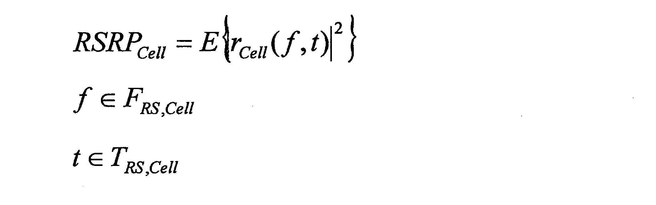
rcell(f,t)は、周波数インデックスf及び時間インデックスtのリソースエレメントの受信信号である。FRS,Cellは、周波数インデックスの集合であり、TRS,Cellは、時間インデックスの集合である。E{}は、平均処理を意味する。RSRPは、リニア値であってもよく、又はデシベル値であってもよい。ただし、平均化処理は、リニア値での平均化処理であることが望ましい。
(a-2)通信品質
例えば、上記測定は、セルについての通信品質の測定を含む。より具体的には、例えば、上記測定は、リファレンス信号の受信品質の測定を含む。一例として、上記測定は、RSRQ(Reference Signal Received Quality)の測定を含む。上記測定は、SNR(Signal-to-Noise Ratio)、SINR(Signal-to-Interference-plus-Noise Ratio)、CSI(Channel State Information)、及び/又はCQI(Channel Quality Indicator)などの測定を含んでもよい。RSRQは、例えば以下のように算出される。
例えば、上記測定は、セルについての通信品質の測定を含む。より具体的には、例えば、上記測定は、リファレンス信号の受信品質の測定を含む。一例として、上記測定は、RSRQ(Reference Signal Received Quality)の測定を含む。上記測定は、SNR(Signal-to-Noise Ratio)、SINR(Signal-to-Interference-plus-Noise Ratio)、CSI(Channel State Information)、及び/又はCQI(Channel Quality Indicator)などの測定を含んでもよい。RSRQは、例えば以下のように算出される。

Nは、対象リソースブロックの数である。RSSIは、チャネル帯域幅にわたる受信信号の電力であり、以下のように算出される。

r(t)は、時間インデックスtの受信信号である。E{}は、平均処理を意味する。RSSIは、リニア値であってもよく、又はデシベル値であってもよい。ただし、平均化処理は、リニア値での平均化処理であることが望ましい。
(a-3)リファレンス信号
例えば、上記リファレンス信号は、CRS/CSRS(Cell-specific Reference Signal)である。あるいは、上記リファレンス信号は、DRS/DMRS(Demodulation Reference Signal)、CSIRS(Channel State Information Reference Signal)又はPRS(Positioning Reference Signal)であってもよい。
例えば、上記リファレンス信号は、CRS/CSRS(Cell-specific Reference Signal)である。あるいは、上記リファレンス信号は、DRS/DMRS(Demodulation Reference Signal)、CSIRS(Channel State Information Reference Signal)又はPRS(Positioning Reference Signal)であってもよい。
(b)測定報告
端末装置200は、セルについての測定報告を行う。即ち、端末装置200は、基地局に測定結果を報告(又はフィードバック)する。例えば、当該基地局は、端末装置200にとってのサービングセルの基地局(例えば、基地局100)である。
端末装置200は、セルについての測定報告を行う。即ち、端末装置200は、基地局に測定結果を報告(又はフィードバック)する。例えば、当該基地局は、端末装置200にとってのサービングセルの基地局(例えば、基地局100)である。
例えば、端末装置200は、所定のイベントの条件が満たされる場合に、測定報告を行う。例えば、当該所定のイベントは、3GPP(Third Generation Partnership Project)で定められているイベントA1~A6及びB1~B2のうちのいずれかである。あるいは、上記所定のイベントは、別のものであってもよい。
例えば、端末装置200は、測定結果である値(例えば、RSRP及びRSRQなど)そのものを報告してもよく、又は測定結果である値に対応するインデックスを報告してもよい。
(5)セルの選択
基地局100は、端末装置200(即ち、ユーザ)のためにセルを選択する。例えば、基地局100は、端末装置200により報告される測定結果に基づいて、セルを選択する。
基地局100は、端末装置200(即ち、ユーザ)のためにセルを選択する。例えば、基地局100は、端末装置200により報告される測定結果に基づいて、セルを選択する。
例えば、基地局100は、端末装置200のハンドオーバのターゲットセルを選択する。即ち、基地局100は、ターゲットセルへの端末装置200のハンドオーバを決定する。当該ハンドオーバは、基地局間ハンドオーバであってもよく、又は周波数間ハンドオーバであってもよい。
例えば、基地局100は、端末装置200のためのセカンダリセル(又はセカンダリコンポーネントキャリア)を選択する。即ち、基地局100は、端末装置200のためのセカンダリセルの追加又は削除を決定する。
(6)多元接続
例えば、基地局100は、直交多元接続により、複数の端末装置との無線通信を行う。一例として、当該直交多元接続は、OFDMAである。別の例として、上記直交多元接続は、FDMA(Frequency Division Multiple Access)又はTDMA(Time Division Multiple Access)であってもよい。
例えば、基地局100は、直交多元接続により、複数の端末装置との無線通信を行う。一例として、当該直交多元接続は、OFDMAである。別の例として、上記直交多元接続は、FDMA(Frequency Division Multiple Access)又はTDMA(Time Division Multiple Access)であってもよい。
あるいは、基地局100は、非直交多元接続により、複数の端末装置との無線通信を行ってもよい。一例として、上記非直交多元接続は、SPC多元接続であってもよい。
(7)干渉除去
例えば、端末装置200は、干渉除去のケイパビリティを有する場合には、受信信号から干渉を除去する。より具体的には、例えば、端末装置200は、受信信号からセル間干渉(即ち、周辺セルからの干渉)を除去する。非直交多元接続が用いられる場合に、端末装置200は、受信信号からセル内干渉を除去してもよい。
例えば、端末装置200は、干渉除去のケイパビリティを有する場合には、受信信号から干渉を除去する。より具体的には、例えば、端末装置200は、受信信号からセル間干渉(即ち、周辺セルからの干渉)を除去する。非直交多元接続が用いられる場合に、端末装置200は、受信信号からセル内干渉を除去してもよい。
例えば、端末装置200は、干渉除去のケイパビリティを有しない場合には、受信信号から干渉を除去しない。
なお、本明細書において、「干渉除去」とは、所望信号にとっての干渉信号のレプリカを生成して除去する手法(即ち、狭義の干渉除去)であってもよく、又は、このような狭義の干渉除去に加えて干渉抑圧(Interference Suppression)などをさらに含む手法(即ち、広義の干渉除去)であってもよい。
<<3.各装置の構成>>
続いて、図7及び図8を参照して、本開示の実施形態に係る基地局100及び端末装置200の構成を説明する
続いて、図7及び図8を参照して、本開示の実施形態に係る基地局100及び端末装置200の構成を説明する
<3.1.基地局の構成>
まず、図7を参照して、本開示の実施形態に係る基地局100の構成の一例を説明する。図7は、本開示の実施形態に係る基地局100の構成の一例を示すブロック図である。図7を参照すると、基地局100は、アンテナ部110、無線通信部120、ネットワーク通信部130、記憶部140及び処理部150を備える。
まず、図7を参照して、本開示の実施形態に係る基地局100の構成の一例を説明する。図7は、本開示の実施形態に係る基地局100の構成の一例を示すブロック図である。図7を参照すると、基地局100は、アンテナ部110、無線通信部120、ネットワーク通信部130、記憶部140及び処理部150を備える。
(1)アンテナ部110
アンテナ部110は、無線通信部120により出力される信号を電波として空間に放射する。また、アンテナ部110は、空間の電波を信号に変換し、当該信号を無線通信部120へ出力する。
アンテナ部110は、無線通信部120により出力される信号を電波として空間に放射する。また、アンテナ部110は、空間の電波を信号に変換し、当該信号を無線通信部120へ出力する。
(2)無線通信部120
無線通信部120は、信号を送受信する。例えば、無線通信部120は、端末装置へのダウンリンク信号を送信し、端末装置からのアップリンク信号を受信する。
無線通信部120は、信号を送受信する。例えば、無線通信部120は、端末装置へのダウンリンク信号を送信し、端末装置からのアップリンク信号を受信する。
(3)ネットワーク通信部130
ネットワーク通信部130は、情報を送受信する。例えば、ネットワーク通信部130は、他のノードへの情報を送信し、他のノードからの情報を受信する。例えば、上記他のノードは、他の基地局及びコアネットワークノードを含む。
ネットワーク通信部130は、情報を送受信する。例えば、ネットワーク通信部130は、他のノードへの情報を送信し、他のノードからの情報を受信する。例えば、上記他のノードは、他の基地局及びコアネットワークノードを含む。
(4)記憶部140
記憶部140は、基地局100の動作のためのプログラム及び様々なデータを一時的に又は恒久的に記憶する。
記憶部140は、基地局100の動作のためのプログラム及び様々なデータを一時的に又は恒久的に記憶する。
(5)処理部150
処理部150は、基地局100の様々な機能を提供する。処理部150は、情報取得部151及び制御部153を含む。なお、処理部150は、これらの構成要素以外の他の構成要素をさらに含み得る。即ち、処理部150は、これらの構成要素の動作以外の動作も行い得る。
処理部150は、基地局100の様々な機能を提供する。処理部150は、情報取得部151及び制御部153を含む。なお、処理部150は、これらの構成要素以外の他の構成要素をさらに含み得る。即ち、処理部150は、これらの構成要素の動作以外の動作も行い得る。
情報取得部151及び制御部153は、後に詳細に説明する。
<3.2.端末装置の構成>
まず、図8を参照して、本開示の実施形態に係る端末装置200の構成の一例を説明する。図8は、本開示の実施形態に係る端末装置200の構成の一例を示すブロック図である。図8を参照すると、端末装置200は、アンテナ部210、無線通信部220、記憶部230及び処理部240を備える。
まず、図8を参照して、本開示の実施形態に係る端末装置200の構成の一例を説明する。図8は、本開示の実施形態に係る端末装置200の構成の一例を示すブロック図である。図8を参照すると、端末装置200は、アンテナ部210、無線通信部220、記憶部230及び処理部240を備える。
(1)アンテナ部210
アンテナ部210は、無線通信部220により出力される信号を電波として空間に放射する。また、アンテナ部210は、空間の電波を信号に変換し、当該信号を無線通信部220へ出力する。
アンテナ部210は、無線通信部220により出力される信号を電波として空間に放射する。また、アンテナ部210は、空間の電波を信号に変換し、当該信号を無線通信部220へ出力する。
(2)無線通信部220
無線通信部220は、信号を送受信する。例えば、無線通信部220は、基地局からのダウンリンク信号を受信し、基地局へのアップリンク信号を送信する。
無線通信部220は、信号を送受信する。例えば、無線通信部220は、基地局からのダウンリンク信号を受信し、基地局へのアップリンク信号を送信する。
(3)記憶部230
記憶部230は、端末装置200の動作のためのプログラム及び様々なデータを一時的に又は恒久的に記憶する。
記憶部230は、端末装置200の動作のためのプログラム及び様々なデータを一時的に又は恒久的に記憶する。
(4)処理部240
処理部240は、端末装置200の様々な機能を提供する。処理部240は、情報取得部241及び制御部243を含む。なお、処理部240は、これらの構成要素以外の他の構成要素をさらに含み得る。即ち、処理部240は、これらの構成要素の動作以外の動作も行い得る。
処理部240は、端末装置200の様々な機能を提供する。処理部240は、情報取得部241及び制御部243を含む。なお、処理部240は、これらの構成要素以外の他の構成要素をさらに含み得る。即ち、処理部240は、これらの構成要素の動作以外の動作も行い得る。
情報取得部241及び制御部243は、後に詳細に説明する。
<<4.本開示の実施形態に係る技術的特徴>>
続いて、図9~図30を参照して、本開示の実施形態に係る技術的特徴を説明する。
続いて、図9~図30を参照して、本開示の実施形態に係る技術的特徴を説明する。
<4.1.ユーザパラメータに従った測定/測定報告>
本開示の実施形態によれば、端末装置200(情報取得部241)は、干渉除去に関連する、ユーザのためのパラメータ(以下、「ユーザパラメータ」と呼ぶ)を取得する。そして、端末装置200(制御部243)は、上記ユーザパラメータに従って、セルについての測定又は測定報告を行う。なお、上記ユーザは、端末装置200である。
本開示の実施形態によれば、端末装置200(情報取得部241)は、干渉除去に関連する、ユーザのためのパラメータ(以下、「ユーザパラメータ」と呼ぶ)を取得する。そして、端末装置200(制御部243)は、上記ユーザパラメータに従って、セルについての測定又は測定報告を行う。なお、上記ユーザは、端末装置200である。
(1)セル
上記セルは、上記ユーザ(即ち、端末装置200)にとってのサービングセルであってもよく、上記ユーザ(即ち、端末装置200)にとっての周辺セルであってもよい。
上記セルは、上記ユーザ(即ち、端末装置200)にとってのサービングセルであってもよく、上記ユーザ(即ち、端末装置200)にとっての周辺セルであってもよい。
(2)パラメータ
(a)干渉除去のケイパビリティに応じた値
例えば、上記ユーザパラメータは、上記ユーザ(即ち、端末装置200)の干渉除去のケイパビリティに応じた値である。
(a)干渉除去のケイパビリティに応じた値
例えば、上記ユーザパラメータは、上記ユーザ(即ち、端末装置200)の干渉除去のケイパビリティに応じた値である。
具体的には、例えば、上記ユーザパラメータは、上記ユーザが干渉除去のケイパビリティを有する場合により大きく、上記ユーザが干渉除去のケイパビリティを有しない場合により小さい。
(b)セル/セルの種類に応じた値
例えば、上記ユーザパラメータは、上記セル又は上記セルの種類に応じた値である。
例えば、上記ユーザパラメータは、上記セル又は上記セルの種類に応じた値である。
具体的には、例えば、上記ユーザパラメータは、上記セルがスモールセルである場合により大きく、上記セルがマクロセルである場合により小さい。
(c)パラメータの例
第1の例として、上記ユーザパラメータは、干渉除去に関連する上記ユーザ(即ち、端末装置200)のためのオフセット(以下、「ユーザオフセット」と呼ぶ)である。当該ユーザオフセットは、測定報告をトリガするイベントの条件に含まれる。端末装置200(制御部243)は、上記ユーザオフセットに従って、上記セルについての測定報告を行う。
第1の例として、上記ユーザパラメータは、干渉除去に関連する上記ユーザ(即ち、端末装置200)のためのオフセット(以下、「ユーザオフセット」と呼ぶ)である。当該ユーザオフセットは、測定報告をトリガするイベントの条件に含まれる。端末装置200(制御部243)は、上記ユーザオフセットに従って、上記セルについての測定報告を行う。
第2の例として、上記ユーザパラメータは、干渉除去に関連する上記ユーザ(即ち、端末装置200)のためのタイマ値であって、測定報告のために用いられるタイマに設定される上記タイマ値である。端末装置200(制御部243)は、上記タイマ値に従って、上記セルについての測定報告を行う。
第3の例として、上記ユーザパラメータは、干渉除去に関連する上記ユーザ(即ち、端末装置200)のための補正値であって、通信品質の測定に用いられる上記補正値である。端末装置200(制御部243)は、上記補正値に従って、上記セルについての通信品質の測定を行う。
これらの例の各々は、後に詳細に説明する。
(d)パラメータの通知
例えば、基地局100(情報取得部151)は、干渉除去に関連する、ユーザ(即ち、端末装置200)のためのパラメータ(即ち、ユーザパラメータ)を取得する。そして、基地局100(制御部153)は、上記ユーザパラメータに従ってセルについての測定又は測定報告を行う上記ユーザ(即ち、端末装置200)に、上記パラメータを通知する。
例えば、基地局100(情報取得部151)は、干渉除去に関連する、ユーザ(即ち、端末装置200)のためのパラメータ(即ち、ユーザパラメータ)を取得する。そして、基地局100(制御部153)は、上記ユーザパラメータに従ってセルについての測定又は測定報告を行う上記ユーザ(即ち、端末装置200)に、上記パラメータを通知する。
例えば、端末装置200は、端末装置200(即ち、ユーザ)の干渉除去のケイパビリティを基地局100に通知し、基地局100(処理部150)は、当該ケイパビリティに基づいて、ユーザパラメータを決定する。そして、基地局100(情報取得部151)は、当該ユーザパラメータを取得し、基地局100(制御部153)は、当該ユーザパラメータを端末装置200(即ち、上記ユーザ)に通知する。
例えば、基地局100は、端末装置200への個別のシグナリングにより、上記ユーザパラメータを端末装置200に通知する。具体的には、例えば、基地局100は、上記ユーザパラメータを含むメッセージを、端末装置200へ送信する。
なお、基地局100は、2つ以上のユーザパラメータ候補をブロードキャストしてもよい。具体的には、基地局100は、上記2つ以上のユーザパラメータ候補を含むシステム情報を送信してもよい。そして、端末装置200が、(例えば端末装置200の干渉除去のケイパビリティに基づいて)上記2つ以上のユーザパラメータの候補のうちの1つを、自らのユーザパラメータとして選択してもよい。あるいは、端末装置200は、自らのユーザパラメータを予め保持してもよく、この場合に、基地局100は、ユーザパラメータを端末装置200に通知しなくてもよい。
(3)第1の例(ユーザオフセットに従った測定報告)
上述したように、第1の例として、上記ユーザパラメータは、干渉除去に関連する上記ユーザ(即ち、端末装置200)のためのオフセット(即ち、ユーザオフセット)である。当該ユーザオフセットは、測定報告をトリガするイベントの条件に含まれる。端末装置200(制御部243)は、上記ユーザオフセットに従って、上記セルについての測定報告を行う。
上述したように、第1の例として、上記ユーザパラメータは、干渉除去に関連する上記ユーザ(即ち、端末装置200)のためのオフセット(即ち、ユーザオフセット)である。当該ユーザオフセットは、測定報告をトリガするイベントの条件に含まれる。端末装置200(制御部243)は、上記ユーザオフセットに従って、上記セルについての測定報告を行う。
(a)ユーザオフセット
例えば、上記ユーザオフセットは、上記条件において測定結果に加算される値である。例えば、当該測定結果は、リファレンス信号の受信電力、又はリファレンス信号の受信品質である。
例えば、上記ユーザオフセットは、上記条件において測定結果に加算される値である。例えば、当該測定結果は、リファレンス信号の受信電力、又はリファレンス信号の受信品質である。
より具体的には、例えば、上記ユーザオフセットは、測定報告をトリガするイベントの条件に含まれ、当該条件においてRSRP又はRSRQに加算される。
(b)既存のイベントへのオフセットの適用
例えば、上記イベントは、3GPPで定められているイベントA1~A6及びB1~B2のうちのいずれかである。即ち、上記ユーザオフセットは、イベントA1~A6及びB1~B2のうちの1つ以上のイベントに適用される。
例えば、上記イベントは、3GPPで定められているイベントA1~A6及びB1~B2のうちのいずれかである。即ち、上記ユーザオフセットは、イベントA1~A6及びB1~B2のうちの1つ以上のイベントに適用される。
なお、以下の説明ではイベント間で同一の記号が用いられるが、同一の記号がイベント間で異なる値を有し得るということに留意すべきである。
(b―1)イベントA1
イベントA1は、サービングセルについての測定結果が閾値を上回るというイベントである。例えば、ユーザオフセットがイベントA1に適用される場合に、イベントA1の条件は、以下のように表される。
イベントA1は、サービングセルについての測定結果が閾値を上回るというイベントである。例えば、ユーザオフセットがイベントA1に適用される場合に、イベントA1の条件は、以下のように表される。

上述した式において、Msは、サービングセルについての測定結果(例えば、RSRQ又はRSRPなど)であり、Ouは、ユーザオフセットであり、Hysは、イベントの頻発を回避するためのヒステリシスであり、Threshは、閾値である。
例えば、ユーザオフセットOuがより大きいほど、イベントA1が発生しやすくなる(即ち、イベントA1の条件が満たされやすくなる)。一方、ユーザオフセットOuがより小さいほど、イベントA1が発生しにくくなる(即ち、イベントA1の条件が満たされにくくなる)。
なお、上述した式は、イベントA1の発生の条件を表すが、イベントA1の終了の条件は、以下のように表されることが可能である。

(b―2)イベントA2
イベントA2は、サービングセルについての測定結果が閾値を下回るというイベントである。例えば、ユーザオフセットがイベントA2に適用される場合に、イベントA2の条件は、以下のように表される。
イベントA2は、サービングセルについての測定結果が閾値を下回るというイベントである。例えば、ユーザオフセットがイベントA2に適用される場合に、イベントA2の条件は、以下のように表される。

上述した式に含まれる各記号の説明は、イベントA1に関連して説明したとおりである。
例えば、ユーザオフセットOuがより大きいほど、イベントA2が発生しにくくなる(即ち、イベントA2の条件が満たされにくくなる)。一方、ユーザオフセットOuがより小さいほど、イベントA2が発生しやすくなる(即ち、イベントA1の条件が満たされやすくなる)。
なお、上述した式は、イベントA2の発生の条件を表すが、イベントA2の終了の条件は、以下のように表されることが可能である。

(b―3)イベントA3
イベントA3は、周辺セルについての測定結果がサービングセルについての測定結果をオフセットだけ上回るというイベントである。例えば、ユーザオフセットがイベントA3に適用される場合に、イベントA3の条件は、以下のように表される。
イベントA3は、周辺セルについての測定結果がサービングセルについての測定結果をオフセットだけ上回るというイベントである。例えば、ユーザオフセットがイベントA3に適用される場合に、イベントA3の条件は、以下のように表される。

上述した式において、Mnは、周辺セルについての測定結果(例えば、RSRQ又はRSRPなど)であり、Ofnは、上記周辺セルの周波数についての周波数オフセットであり、Ocnは、上記周辺セルについてのセルオフセットであり、Ounは、上記周辺セルに対応するユーザオフセットであり、Hysは、イベントの頻発を回避するためのヒステリシスである。
さらに、上述した式において、Mpは、プライマリセルについての測定結果(例えば、RSRQ又はRSRPなど)であり、Ofpは、上記プライマリセルの周波数についての周波数オフセットであり、Ocpは、上記プライマリセルについてのセルオフセットであり、Oupは、上記プライマリセルに対応するユーザオフセットである。Offは、イベントA3のオフセットである。なお、プライマリセルは、サービングセルのうちの1つである。
例えば、周辺セルに対応するユーザオフセットOunがより大きいほど、イベントA3が発生しやすくなる(即ち、イベントA3の条件が満たされやすくなる)。一方、プライマリセルに対応するユーザオフセットOupがより大きいほど、イベントA3が発生しにくくなる(即ち、イベントA3の条件が満たされにくくなる)。
なお、上述した式は、イベントA3の発生の条件を表すが、イベントA3の終了の条件は、以下のように表されることが可能である。

(b―4)イベントA4
イベントA4は、周辺セルについての測定結果が閾値を上回るというイベントである。例えば、ユーザオフセットがイベントA4に適用される場合に、イベントA4の条件は、以下のように表される。
イベントA4は、周辺セルについての測定結果が閾値を上回るというイベントである。例えば、ユーザオフセットがイベントA4に適用される場合に、イベントA4の条件は、以下のように表される。

上述した式に含まれる各記号の説明は、イベントA3に関連して説明したとおりである。
例えば、ユーザオフセットOunがより大きいほど、イベントA4が発生しやすくなる(即ち、イベントA4の条件が満たされやすくなる)。一方、ユーザオフセットOunがより小さいほど、イベントA4が発生しにくくなる(即ち、イベントA4の条件が満たされにくくなる)。
なお、上述した式は、イベントA4の発生の条件を表すが、イベントA4の終了の条件は、以下のように表されることが可能である。

(b―5)イベントA5
イベントA5は、サービングセルについての測定結果が第1の閾値を下回り、周辺セルについての測定結果が第2の閾値を上回るというイベントである。例えば、ユーザオフセットがイベントA5に適用される場合に、イベントA5の条件は、以下のように表される。
イベントA5は、サービングセルについての測定結果が第1の閾値を下回り、周辺セルについての測定結果が第2の閾値を上回るというイベントである。例えば、ユーザオフセットがイベントA5に適用される場合に、イベントA5の条件は、以下のように表される。

上述した式に含まれる各記号の説明は、Thresh1及びThresh2を除き、イベントA3に関連して説明したとおりである。Thresh1は、第1の閾値であり、Thresh2は、第2の閾値である。
例えば、プライマリセルに対応するユーザオフセットOupがより大きいほど、イベントA5が発生しにくくなる(即ち、イベントA5の条件が満たされにくくなる)。一方、周辺セルに対応するユーザオフセットOunがより大きいほど、イベントA5が発生しやすくなる(即ち、イベントA5の条件が満たされやすくなる)。
なお、上述した式は、イベントA5の発生の条件を表すが、イベントA5の終了の条件は、以下のように表されることが可能である。

(b―6)イベントA6
イベントA6は、周辺セルについての測定結果がセカンダリセルについての測定結果をオフセットだけ上回るというイベントである。例えば、ユーザオフセットがイベントA6に適用される場合に、イベントA6の条件は、以下のように表される。
イベントA6は、周辺セルについての測定結果がセカンダリセルについての測定結果をオフセットだけ上回るというイベントである。例えば、ユーザオフセットがイベントA6に適用される場合に、イベントA6の条件は、以下のように表される。

上述した式において、Mnは、周辺セルについての測定結果(例えば、RSRQ又はRSRPなど)であり、Ofnは、上記周辺セルの周波数についての周波数オフセットであり、Ocnは、上記周辺セルについてのセルオフセットであり、Ounは、上記周辺セルに対応するユーザオフセットであり、Hysは、イベントの頻発を回避するためのヒステリシスである。
さらに、上述した式において、Msは、セカンダリセルについての測定結果(例えば、RSRQ又はRSRPなど)であり、Ofsは、上記セカンダリセルの周波数についての周波数オフセットであり、Ocsは、上記セカンダリセルについてのセルオフセットであり、Oupは、上記セカンダリセルに対応するユーザオフセットである。Offは、イベントA6のオフセットである。
例えば、周辺セルに対応するユーザオフセットOunがより大きいほど、イベントA6が発生しやすくなる(即ち、イベントA6の条件が満たされやすくなる)。一方、プライマリセルに対応するユーザオフセットOusがより大きいほど、イベントA6が発生しにくくなる(即ち、イベントA6の条件が満たされにくくなる)。
なお、上述した式は、イベントA6の発生の条件を表すが、イベントA6の終了の条件は、以下のように表されることが可能である。

(b―7)イベントB1
イベントB1は、異なるRAT(Radio Access Technology)の周辺セルについての測定結果が閾値を上回るというイベントである。例えば、ユーザオフセットがイベントB1に適用される場合に、イベントB1の条件は、以下のように表される。
イベントB1は、異なるRAT(Radio Access Technology)の周辺セルについての測定結果が閾値を上回るというイベントである。例えば、ユーザオフセットがイベントB1に適用される場合に、イベントB1の条件は、以下のように表される。

上述した式に含まれる各記号の説明は、イベントA3に関連して説明したとおりである。
例えば、ユーザオフセットOunがより大きいほど、イベントB1が発生しやすくなる(即ち、イベントB1の条件が満たされやすくなる)。一方、ユーザオフセットOunがより小さいほど、イベントB1が発生しにくくなる(即ち、イベントB1の条件が満たされにくくなる)。
なお、上述した式は、イベントB1の発生の条件を表すが、イベントB1の終了の条件は、以下のように表されることが可能である。

(b―8)イベントB2
イベントB2は、プライマリセルについての測定結果が第1の閾値を下回り、異なるRATの周辺セルについての測定結果が第2の閾値を上回るというイベントである。例えば、ユーザオフセットがイベントB2に適用される場合に、イベントB2の条件は、以下のように表される。
イベントB2は、プライマリセルについての測定結果が第1の閾値を下回り、異なるRATの周辺セルについての測定結果が第2の閾値を上回るというイベントである。例えば、ユーザオフセットがイベントB2に適用される場合に、イベントB2の条件は、以下のように表される。

上述した式に含まれる各記号の説明は、Thresh1及びThresh2を除き、イベントA3に関連して説明したとおりである。Thresh1は、第1の閾値であり、Thresh2は、第2の閾値である。
例えば、プライマリセルに対応するユーザオフセットOupがより大きいほど、イベントB2が発生しにくくなる(即ち、イベントB2の条件が満たされにくくなる)。一方、周辺セルに対応するユーザオフセットOunがより大きいほど、イベントB2が発生しやすくなる(即ち、イベントB2の条件が満たされやすくなる)。
(c)新たなイベントへのオフセットの適用
上記イベントは、上述した既存のイベントではなく、新規のイベントであってもよい。
上記イベントは、上述した既存のイベントではなく、新規のイベントであってもよい。
さらに、当該新規イベントは、ユーザが干渉除去のケイパビリティを有する場合に限り適用されるイベントであってもよい。
例えば、以下のような条件の下で、第1の新規イベント及び第2の新規イベントが適用されてもよい。

なお、例えば、上記サービングセル及び上記周辺セルの一方は、マクロセルであり、他方はスモールセルである。例えば、上記サービングセルは、プライマリセルである。
(c-1)第1の新規イベント
-第1の新規イベントの条件
例えば、ユーザのプライマリセルの受信電力が、周辺セルの受信電力よりも大きい(又は当該受信電力以上である)場合に、第1の新規イベントが適用される。例えば、当該第1の新規イベントの条件は、以下のとおりである。
-第1の新規イベントの条件
例えば、ユーザのプライマリセルの受信電力が、周辺セルの受信電力よりも大きい(又は当該受信電力以上である)場合に、第1の新規イベントが適用される。例えば、当該第1の新規イベントの条件は、以下のとおりである。

上述した式において、Mp1は、プライマリセルについての受信電力(例えば、RSRP)であり、Ofpは、上記プライマリセルの周波数についての周波数オフセットであり、Ocpは、上記プライマリセルについてのセルオフセットであり、Oupは、上記プライマリセルに対応するユーザオフセットである。Hysは、イベントの頻発を回避するためのヒステリシスである。
上述した式において、Mn1は、周辺セルについての受信電力(例えば、RSRP)であり、Mn2は、周辺セルについての通信品質(例えば、RSRQ)であり、Ofnは、上記周辺セルの周波数についての周波数オフセットであり、Ocnは、上記周辺セルについてのセルオフセットであり、Ounは、上記周辺セルに対応するユーザオフセットである。
上述した式には、イコールなしの不等号が含まれているが、イコールなしの不等号の代わりに、イコール付きの不等号が含まれてもよい。
例えば、周辺セルに対応するユーザオフセットOunがより大きいほど、上記第1の新規イベントが発生しやすくなる(即ち、上記条件が満たされやすくなる)。一方、プライマリセルに対応するユーザオフセットOupがより大きいほど、上記第1の新規イベントが発生しにくくなる(即ち、上記条件が満たされにくくなる)。
なお、上述した式は、上記第1の新規イベントの発生の条件を表すが、上記第1の新規イベントの終了の条件は、以下のように表されることが可能である。

-導出の過程
プライマリセルについての通信品質Qp(例えば、SINR)は、一般的に、プライマリセルについての受信電力Pp、周辺セルについての受信電力Pn及びノイズnを用いて、以下のように表される。
プライマリセルについての通信品質Qp(例えば、SINR)は、一般的に、プライマリセルについての受信電力Pp、周辺セルについての受信電力Pn及びノイズnを用いて、以下のように表される。

一方、周辺セルについての通信品質Qnは、一般的に、以下のように表される。

例えば、対象の信号の受信電力よりも、他の信号の受信電力の方が大きい場合には、当該他の信号は、干渉信号として除去されることが可能である。そのため、ユーザが干渉除去のケイパビリティを有し、且つ、周辺セルの信号(対象の信号)の受信電力Pnよりもプライマリセルの信号(干渉信号)の受信電力Ppの方が大きい場合には、周辺セルの通信品質Qnは、干渉除去の結果として、以下のように表されることが可能である。

例えば、以下のように、周辺セルについての通信品質Qnが、プライマリセルの通信品質Qpよりも良好になる場合には、ハンドオーバ(即ち、プライマリセルの変更)を行うことが望ましい。

この式は、通信品質Qp及び通信品質Qnへの代入により、以下のように展開することができる。


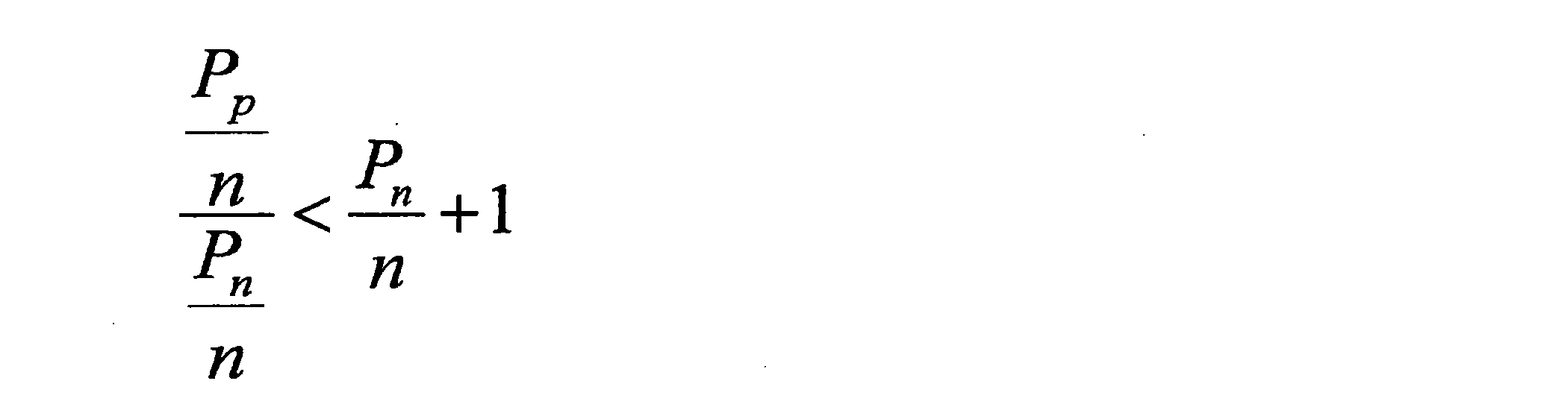


なお、右辺の1を無視すると、上述した式は、以下のように表されることが可能である。

なお、受信電力Pp、受信電力Ps及び通信品質Qnは、上記第1の新規イベントの上記条件におけるMp1、Mn1、Mn2にそれぞれ対応するので、デシベル形式への変換を通じて、この式から上述した上記第1の新規イベントの上記条件が導かれる。
(c-1)第2の新規イベント
-第2の新規イベントの条件
例えば、ユーザのプライマリセルの受信電力が、周辺セルの受信電力よりも小さい(又は当該受信電力以下である)場合に、第2の新規イベントが適用される。例えば、当該第2の新規イベントの条件は、以下のとおりである。
-第2の新規イベントの条件
例えば、ユーザのプライマリセルの受信電力が、周辺セルの受信電力よりも小さい(又は当該受信電力以下である)場合に、第2の新規イベントが適用される。例えば、当該第2の新規イベントの条件は、以下のとおりである。

Mp1は、プライマリセルについての受信電力(例えば、RSRP)であり、Mn2は、プライマリセルについての通信品質(例えば、RSRQ)であり、Ofpは、上記プライマリセルの周波数についての周波数オフセットであり、Ocpは、上記プライマリセルについてのセルオフセットであり、Oupは、上記プライマリセルに対応するユーザオフセットである。Hysは、イベントの頻発を回避するためのヒステリシスである。
上述した式において、Mn1は、周辺セルについての受信電力(例えば、RSRP)であり、Ofnは、上記周辺セルの周波数についての周波数オフセットであり、Ocnは、上記周辺セルについてのセルオフセットであり、Ounは、上記周辺セルに対応するユーザオフセットである。
上述した式には、イコールなしの不等号が含まれているが、イコールなしの不等号の代わりに、イコール付きの不等号が含まれてもよい。
例えば、周辺セルに対応するユーザオフセットOunがより大きいほど、上記第2の新規イベントが発生しやすくなる(即ち、上記条件が満たされやすくなる)。一方、プライマリセルに対応するユーザオフセットOupがより大きいほど、上記第2の新規イベントが発生しにくくなる(即ち、上記条件が満たされにくくなる)。
なお、上述した式は、上記第2の新規イベントの発生の条件を表すが、上記第2の新規イベントの終了の条件は、以下のように表されることが可能である。

-導出の過程
プライマリセルについての通信品質Qp(例えば、SINR)は、一般的に、プライマリセルについての受信電力Pp、周辺セルについての受信電力Pn及びノイズnを用いて、以下のように表される。
プライマリセルについての通信品質Qp(例えば、SINR)は、一般的に、プライマリセルについての受信電力Pp、周辺セルについての受信電力Pn及びノイズnを用いて、以下のように表される。

例えば、対象の信号の受信電力よりも、他の信号の受信電力の方が大きい場合には、当該他の信号は、干渉信号として除去されることが可能である。そのため、ユーザが干渉除去のケイパビリティを有し、且つ、プライマリセルの信号(対象の信号)の受信電力Ppよりも周辺セルの信号(干渉信号)の受信電力Pnの方が大きい場合には、プライマリセルの通信品質Qpは、干渉除去の結果として、以下のように表されることが可能である。
一方、周辺セルについての通信品質Qnは、一般的に、以下のように表される。

例えば、以下のように、周辺セルについての通信品質Qnが、プライマリセルの通信品質Qpよりも良好になる場合には、ハンドオーバ(即ち、プライマリセルの変更)を行うことが望ましい。

この式は、通信品質Qp及び通信品質Qnへの代入により、以下のように展開することができる。

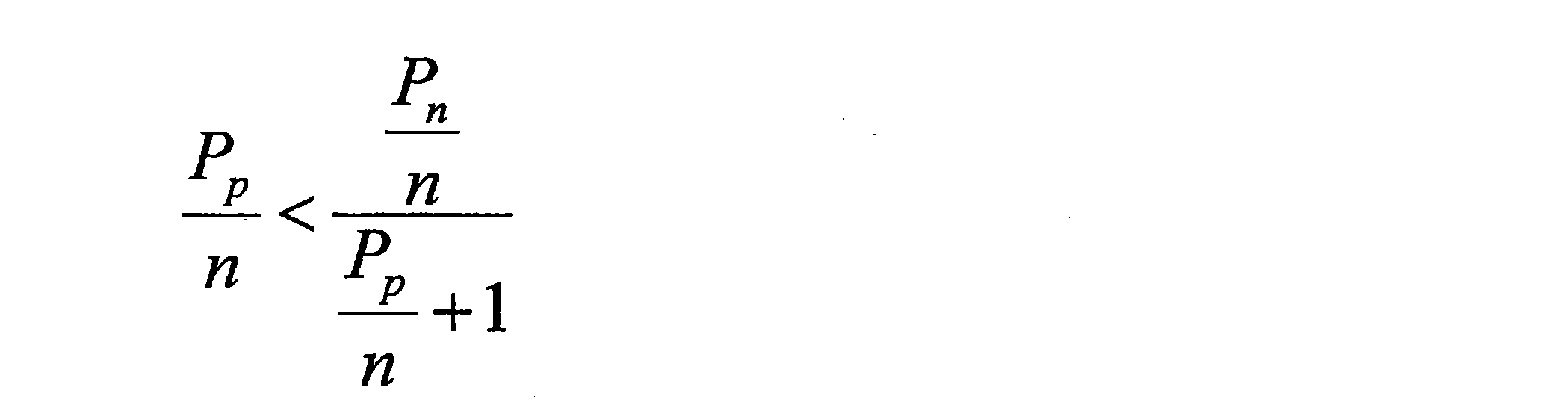
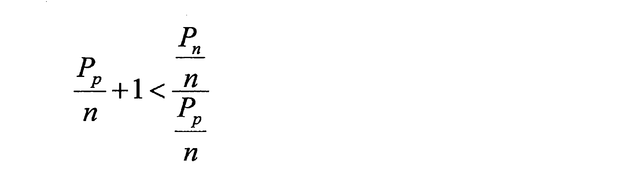


なお、左辺の1を無視すると、上述した式は、以下のように表されることが可能である。

なお、受信電力Pp、通信品質Qp及び受信電力Pnは、上記第2の新規イベントの上記条件におけるMp1、Mp2、Mn1にそれぞれ対応するので、デシベル形式への変換を通じて、この式から上述した上記第2の新規イベントの上記条件が導かれる。
(d)イベントに関する状態遷移
例えば、イベントに関するユーザの状態(以下、「イベント状態」と呼ぶ)が、当該ユーザ内で管理される。以下、図9を参照して当該イベント状態の例を説明する。
例えば、イベントに関するユーザの状態(以下、「イベント状態」と呼ぶ)が、当該ユーザ内で管理される。以下、図9を参照して当該イベント状態の例を説明する。
図9は、イベント状態の例を説明するための説明図である。図9を参照すると、イベント状態は、「In-Event」及び「Out-of-Event」の一方になる。例えば、イベントの発生に応じて、上記イベント状態は、「Out-of-Event」から「In-Event」に遷移する。即ち、ユーザは、「In-Event」に入る(enter)。一方、イベントの終了に応じて、上記イベント状態は、「In-Event」から「Out-of-Event」に遷移する。即ち、ユーザは、「In-Event」から出る(leave)。
(e)ユーザオフセットの例
(e―1)干渉除去のケイパビリティに応じた値
例えば、上記ユーザオフセットは、上記ユーザ(即ち、端末装置200)の干渉除去のケイパビリティに応じた値である。
(e―1)干渉除去のケイパビリティに応じた値
例えば、上記ユーザオフセットは、上記ユーザ(即ち、端末装置200)の干渉除去のケイパビリティに応じた値である。
具体的には、例えば、上記ユーザオフセットは、上記ユーザが干渉除去のケイパビリティを有する場合により大きく、上記ユーザが干渉除去のケイパビリティを有しない場合により小さい。一例として、上記ユーザオフセットは、上記ユーザが干渉除去のケイパビリティを有する場合に正の値であり、上記ユーザが干渉除去のケイパビリティを有しない場合に0(又は上記正の値よりも小さい値)である。別の例として、上記ユーザオフセットは、2つの値のうちの一方をとるのではなく、3つの値のうちの1つをとってもよい。この場合に、上記ユーザオフセットは、上記ユーザがより高性能な干渉除去を行うことが可能である場合により大きい値であり、上記ユーザがより低性能な干渉除去を行うことが可能である場合により小さい値であってもよい。
これにより、例えば、セルについての測定結果が多少悪かったとしても、干渉除去のケイパビリティを有するユーザ(即ち、周辺セルからの干渉をより小さくすることが可能なユーザ)は当該セルを利用することが可能になる。即ち、干渉除去を行うことが可能なユーザは、過酷な条件でもセルを利用し得る。
(e―2)セル/セルの種類に応じた値
例えば、上記ユーザオフセットは、上記セル又は上記セルの種類に応じた値である。
例えば、上記ユーザオフセットは、上記セル又は上記セルの種類に応じた値である。
具体的には、例えば、上記ユーザオフセットは、上記セルがスモールセルである場合により大きく、上記セルがマクロセルである場合により小さい。即ち、上記ユーザオフセットは、スモールセルに対応する場合により大きく、マクロセルに対応する場合により小さい。
これにより、例えば、干渉除去のケイパビリティを有するユーザ(即ち、周辺セルからの干渉をより小さくすることが可能なユーザ)に、マクロセルよりもスモールセルをより優先的に利用させることが可能になる。即ち、干渉除去を行うことが可能なユーザは、過酷な条件でもスモールセルを利用し得る。そのため、スモールセルへのオフローディングが促進され得る。
(e―3)イベント状態に応じた値
上記ユーザオフセットは、イベントの発生と終了とで異なる値を有してもよい。換言すると、上記ユーザオフセットは、イベント状態に応じた値を有してもよい。
上記ユーザオフセットは、イベントの発生と終了とで異なる値を有してもよい。換言すると、上記ユーザオフセットは、イベント状態に応じた値を有してもよい。
例えば、上記ユーザオフセットは、イベントの発生の条件において第1の値を有し、イベントの終了の条件において上記第1の値と異なる第2の値を有してもよい。換言すると、上記ユーザオフセットは、イベント状態が「Out-of-Event」である場合に上記第1の値を有し、イベント状態が「In-Event」である場合に上記第2の値を有してもよい。
(e―4)CRE(Cell Range Extension)
ユーザオフセットに従った測定報告により、例えば、ユーザごとのCREが可能になる。CREは、オフセットにより、特定のセルを選択しやすくする(又は特定のセルを選択しにくくする)手法である。CREは、オフセットにより、特定のセルの広さを調整する手法であるとも言える。一例として、干渉除去のケイパビリティを有するユーザについて、スモールセルがより選択されやすくなる。即ち、スモールセルの広さが、より大きくなるように調整される。
ユーザオフセットに従った測定報告により、例えば、ユーザごとのCREが可能になる。CREは、オフセットにより、特定のセルを選択しやすくする(又は特定のセルを選択しにくくする)手法である。CREは、オフセットにより、特定のセルの広さを調整する手法であるとも言える。一例として、干渉除去のケイパビリティを有するユーザについて、スモールセルがより選択されやすくなる。即ち、スモールセルの広さが、より大きくなるように調整される。
(f)処理の流れ
図10及び図11を参照して、ユーザオフセットに従った測定報告に関する処理の例を説明する。
図10及び図11を参照して、ユーザオフセットに従った測定報告に関する処理の例を説明する。
(f―1)全体の処理
図10は、ユーザオフセットに従った測定報告に関する全体の処理の概略的な流れの一例を示すシーケンス図である。
図10は、ユーザオフセットに従った測定報告に関する全体の処理の概略的な流れの一例を示すシーケンス図である。
端末装置200は、ユーザ(即ち、端末装置200)の干渉除去のケイパビリティを基地局100に通知する(S401)。
基地局100は、上記ケイパビリティに基づいて、干渉除去に関連する上記ユーザ(即ち、端末装置200)のためのオフセット(即ち、ユーザオフセット)を決定する(S403)。そして、基地局100は、当該ユーザオフセットを端末装置200に通知する(S405)。
端末装置200は、セルについての測定を行う(S407)。そして、端末装置200は、上記ユーザオフセットに従って、上記セルについての測定報告をトリガするイベントの条件を判定する(S409)。
上記イベントが発生した場合に(即ち、上記条件が満たされる場合に)、端末装置200は、基地局100への測定報告を行う(S411)。即ち、端末装置200は、測定結果を基地局100に報告する。
なお、基地局100は、上記測定結果に基づいて、端末装置200のためのセルを選択してもよい。当該セルは、端末装置200のハンドオーバのターゲットセルであってもよい。即ち、基地局100は、上記測定結果に基づいて、端末装置200についてのハンドオーバ決定(handover decision)を行ってもよい。あるいは、上記セルは、端末装置200のためのセカンダリセルであってもよい。基地局100は、上記測定結果に基づいて、端末装置200のためのセカンダリセル(セカンダリコンポーネントキャリア)の追加又は削除を決定してもよい。
(f―2)端末装置の処理
図11は、ユーザオフセットに従った測定報告に関する端末装置200の処理の概略的な流れの一例を示すシーケンス図である。当該処理は、図10を参照して説明したステップS407~S411に対応する。
図11は、ユーザオフセットに従った測定報告に関する端末装置200の処理の概略的な流れの一例を示すシーケンス図である。当該処理は、図10を参照して説明したステップS407~S411に対応する。
端末装置200は、セルについての測定を行う(S421)。端末装置200は、必要に応じて測定結果をフィルタリングしてもよい。
測定報告をトリガするイベントの条件の判定のタイミングが到来している場合に(S423:YES)、以降の処理が実行される。そうでなければ(S423:NO)、処理は終了する。
端末装置200は、ユーザオフセットに従って、測定報告をトリガするイベントの条件を判定する(S425)。当該条件は、上記ユーザオフセットを含む。例えば、当該イベントは、イベントA1~A6及びB1~B2のうちのいずれかである。なお、端末装置200が、干渉除去のケイパビリティを有する場合には、上記イベントは、上述した第1の新規イベント又は第2の新規イベントであってもよい。
上記イベントの上記条件が満たされる場合には(S427:YES)、端末装置200は、上記セルについての測定報告を行う(S429)。そうでなければ(S427:NO)、処理は終了する。
例えば以上のように、ユーザパラメータに従って測定報告が行われる。これにより、例えば、干渉除去を考慮した測定報告を行うことが可能になる。より具体的には、例えば、干渉除去が行われるか否かに応じて測定報告の頻度が調整される。
(g)変形例
上述した例では、端末装置200が、ユーザオフセットに従って、セルについての測定報告を行う。しかしながら、本開示の実施形態は係る例に限定されない。変形例として、基地局100が、ユーザオフセットに従って、ユーザのためにセルの選択を行ってもよい。
上述した例では、端末装置200が、ユーザオフセットに従って、セルについての測定報告を行う。しかしながら、本開示の実施形態は係る例に限定されない。変形例として、基地局100が、ユーザオフセットに従って、ユーザのためにセルの選択を行ってもよい。
(g―1)ハンドオーバ
例えば、上記選択は、ユーザ(即ち、端末装置200)のハンドオーバのターゲットセルの選択であってもよい。即ち、基地局100は、ユーザオフセットに従って、ユーザ(即ち、端末装置200)についてのハンドオーバ決定を行ってもよい。
例えば、上記選択は、ユーザ(即ち、端末装置200)のハンドオーバのターゲットセルの選択であってもよい。即ち、基地局100は、ユーザオフセットに従って、ユーザ(即ち、端末装置200)についてのハンドオーバ決定を行ってもよい。
情報取得部151は、ユーザオフセットを取得してもよく、制御部153は、上記ユーザオフセットに従って、ユーザについてのハンドオーバ決定を行ってもよい。
より具体的には、基地局100(制御部153)は、上記ユーザオフセットに従って、ハンドオーバの条件を判定してもよい。一例として、基地局100(制御部153)は、上記測定結果に上記ユーザオフセットを加算し、加算後の値に基づいて、上記条件を判定してもよい。そして、当該条件が満たされる場合に、基地局100(制御部153)は、ターゲットセルへの、ユーザ(端末装置200)のハンドオーバを決定してもよい。即ち、基地局100(制御部153)は、当該ターゲットセルを選択してもよい。
-全体の処理
図12は、ユーザオフセットに従ったハンドオーバ決定に関する全体の処理の概略的な流れの一例を示すシーケンス図である。
図12は、ユーザオフセットに従ったハンドオーバ決定に関する全体の処理の概略的な流れの一例を示すシーケンス図である。
端末装置200は、ユーザ(即ち、端末装置200)の干渉除去のケイパビリティを基地局100に通知する(S441)。
基地局100は、上記ケイパビリティに基づいて、干渉除去に関連する上記ユーザ(即ち、端末装置200)のためのオフセット(即ち、ユーザオフセット)を決定する(S443)。
端末装置200は、セルについての測定を行う(S445)。そして、端末装置200は、上記セルについての測定報告をトリガするイベントの条件を判定する(S447)。
上記イベントが発生した場合に(即ち、上記条件が満たされる場合に)、端末装置200は、基地局100への測定報告を行う(S449)。即ち、端末装置200は、測定結果を基地局100に報告する。
基地局100(制御部153)は、上記ユーザオフセットに従って、ハンドオーバの条件を判定する(S451)。一例として、基地局100(制御部153)は、上記測定結果に上記ユーザオフセットを加算し、加算後の値に基づいて、上記条件を判定する。
上記条件が満たされる場合に、基地局100(制御部153)は、ターゲットセルへの、ユーザ(即ち、端末装置200)のハンドオーバを決定する(S453)。即ち、基地局100(制御部153)は、当該ターゲットセルを選択する。その後、基地局100(制御部153)は、ハンドオーバ手続き(handover procedure)を行う(S455)。
-基地局100の処理
図13は、ユーザオフセットに従ったハンドオーバ決定に関する基地局100の処理の概略的な流れの一例を示すシーケンス図である。当該処理は、図12を参照して説明したステップS451及びS453に対応する。
図13は、ユーザオフセットに従ったハンドオーバ決定に関する基地局100の処理の概略的な流れの一例を示すシーケンス図である。当該処理は、図12を参照して説明したステップS451及びS453に対応する。
基地局100は、ユーザ(即ち、端末装置200)により報告された、セルについての測定結果を取得する(S461)。基地局100は、必要に応じて測定結果をフィルタリングしてもよい。
上記ユーザのハンドオーバの条件の判定のタイミングが到来している場合に(S463:YES)、以降の処理が実行される。そうでなければ(S463:NO)、処理は終了する。
基地局100は、ユーザオフセットに従って、上記ユーザのハンドオーバの条件を判定する(S465)。当該条件は、上記ユーザオフセットを含む。
上記ハンドオーバの上記条件が満たされる場合には(S467:YES)、基地局100は、ターゲットセルへの、上記ユーザ(即ち、端末装置200)のハンドオーバを決定する(S469)。そうでなければ(S467:NO)、処理は終了する。
(g―2)セカンダリセルの追加/削除
例えば、上記選択は、ユーザ(即ち、端末装置200)のためのセカンダリセルの選択であってもよい。即ち、基地局100は、ユーザオフセットに従って、ユーザ(即ち、端末装置200)のためのセカンダリセルの追加又は削除を決定してもよい。
例えば、上記選択は、ユーザ(即ち、端末装置200)のためのセカンダリセルの選択であってもよい。即ち、基地局100は、ユーザオフセットに従って、ユーザ(即ち、端末装置200)のためのセカンダリセルの追加又は削除を決定してもよい。
例えば、情報取得部151は、ユーザオフセットを取得する。そして、制御部153は、上記ユーザオフセットに従って、ユーザのためのセカンダリセルの追加又は削除を決定してもよい。
より具体的には、基地局100(制御部153)は、上記ユーザオフセットに従って、セカンダリセルの追加又は削除の条件を判定してもよい。一例として、基地局100(制御部153)は、上記測定結果に上記ユーザオフセットを加算し、加算後の値に基づいて、上記条件を判定してもよい。そして、当該条件が満たされる場合に、基地局100(制御部153)は、ユーザのためのセカンダリセルの追加又は削除を決定してもよい。即ち、基地局100(制御部153)は、当該セカンダリセルを選択してもよい。
なお、「ユーザオフセットに従ったセカンダリセルの追加又は削除の決定に関する処理」の流れは、「ハンドオーバ」と「セカンダリセルの追加又は削除」という対象の相違を除き、上述した「ユーザオフセットに従ったハンドオーバ決定に関する処理」の流れと同様である。
例えば以上のように、ユーザパラメータに従ってセルが選択される。これにより、例えば、干渉除去を考慮したハンドオーバ又はセカンダリセルの追加/削除を行うことが可能になる。
(4)第2の例(ユーザのためのタイマ値に従った測定報告
上述したように、第2の例として、上記ユーザパラメータは、干渉除去に関連する上記ユーザ(即ち、端末装置200)のためのタイマ値であって、測定報告のために用いられるタイマに設定される上記タイマ値である。端末装置200(制御部243)は、上記タイマ値に従って、上記セルについての測定報告を行う。
上述したように、第2の例として、上記ユーザパラメータは、干渉除去に関連する上記ユーザ(即ち、端末装置200)のためのタイマ値であって、測定報告のために用いられるタイマに設定される上記タイマ値である。端末装置200(制御部243)は、上記タイマ値に従って、上記セルについての測定報告を行う。
(a)タイマ
例えば、上記タイマは、測定報告をトリガするイベントの条件が満たされる場合に開始する。さらに、例えば、上記タイマは、上記条件が満たされなくなる場合にリセットされる。
例えば、上記タイマは、測定報告をトリガするイベントの条件が満たされる場合に開始する。さらに、例えば、上記タイマは、上記条件が満たされなくなる場合にリセットされる。
例えば、端末装置200(制御部243)は、上記タイマの満了後に、上記セルについての測定報告を行う。
(b)タイマ値の例
(b―1)干渉除去のケイパビリティに応じた値
例えば、上記タイマ値は、上記ユーザ(即ち、端末装置200)の干渉除去のケイパビリティに応じた値である。
(b―1)干渉除去のケイパビリティに応じた値
例えば、上記タイマ値は、上記ユーザ(即ち、端末装置200)の干渉除去のケイパビリティに応じた値である。
具体的には、例えば、上記タイマ値は、上記ユーザが干渉除去のケイパビリティを有する場合により大きく、上記ユーザが干渉除去のケイパビリティを有しない場合により小さい。即ち、上記ユーザが干渉除去のケイパビリティを有する場合のタイマ値TICと、上記ユーザが干渉除去のケイパビリティを有しない場合のタイマ値TnoICとは、以下のような関係を有する。

これにより、干渉除去のケイパビリティを有する端末装置のハンドオーバの頻度が減少し得る。より具体的には、例えば、干渉除去のケイパビリティを有する端末装置は、より長い時間にわたりイベントの条件が満たされ続けることを条件として、測定報告を行う。そのため、イベントが発生するが、短時間で当該イベントが終了する場合には、上記端末装置は、測定報告を行わない。そのため、測定報告の頻度が減少し、その結果、ハンドオーバの頻度も減少し得る。干渉除去のケイパビリティを有する端末装置は多少悪い環境であっても通信品質を維持することができるので、このような手法を用いることができる。
図14は、干渉除去のケイパビリティと通信品質との関係の例を説明するための説明図である。図14を参照すると、基地局(例えば、スモールセルの基地局)からの距離と通信品質との関係が示されている。端末装置と基地局との通信についての通信品質は、当該端末装置が当該基地局から離れるに従って低下する。例えば、上記端末装置が、干渉除去のケイパビリティを有する場合には、他のセル(例えば、マクロセル)からの干渉を除去することができる。そのため、上記端末装置が干渉除去のケイパビリティを有しない場合よりも、上記端末装置が干渉除去のケイパビリティを有する場合の方が、上記基地局からの距離の増加に応じた上記通信品質の低下は、より緩やかになる。
(b―2)セル/セルの種類に応じた値
例えば、上記タイマ値は、上記セル又は上記セルの種類に応じた値である。
例えば、上記タイマ値は、上記セル又は上記セルの種類に応じた値である。
具体的には、例えば、上記タイマ値は、上記ユーザ(即ち、端末装置200)のサービングセルがスモールセルである場合により大きく、上記サービングセルがマクロセルである場合により小さい。即ち、上記ユーザのサービングセルがスモールセルである場合のタイマ値TIC,Small、TnoIC,Smallと、上記ユーザのサービングセルがマクロセルである場合のタイマ値TIC,Macro、TnoIC,Macroとは、以下のような関係を有する。
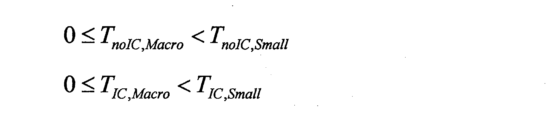
これにより、例えば、干渉除去のケイパビリティを有するユーザ(即ち、周辺セルからの干渉をより小さくすることが可能なユーザ)に、マクロセルよりもスモールセルをより優先的に利用させることが可能になる。即ち、干渉除去を行うことが可能なユーザは、過酷な条件でもスモールセルを利用し得る。そのため、スモールセルへのオフローディングが促進され得る。
(b―3)スケーリングファクタを用いた値の決定
上記タイマ値は、スケーリングファクタにより調整されてもよい。一例として、以下のようなスケーリングファクタが用意される。
上記タイマ値は、スケーリングファクタにより調整されてもよい。一例として、以下のようなスケーリングファクタが用意される。
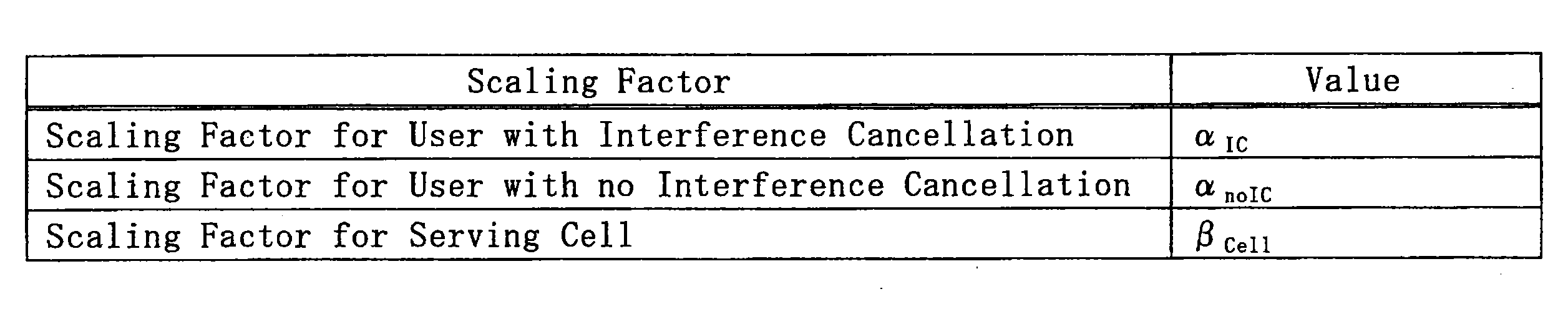
上記ユーザが干渉除去のケイパビリティを有する場合のタイマ値TICと、上記ユーザが干渉除去のケイパビリティを有しない場合のタイマ値TnoICとは、以下のように、上述したスケーリングファクタ及びベースラインタイマ値TBaseとから算出されてもよい。
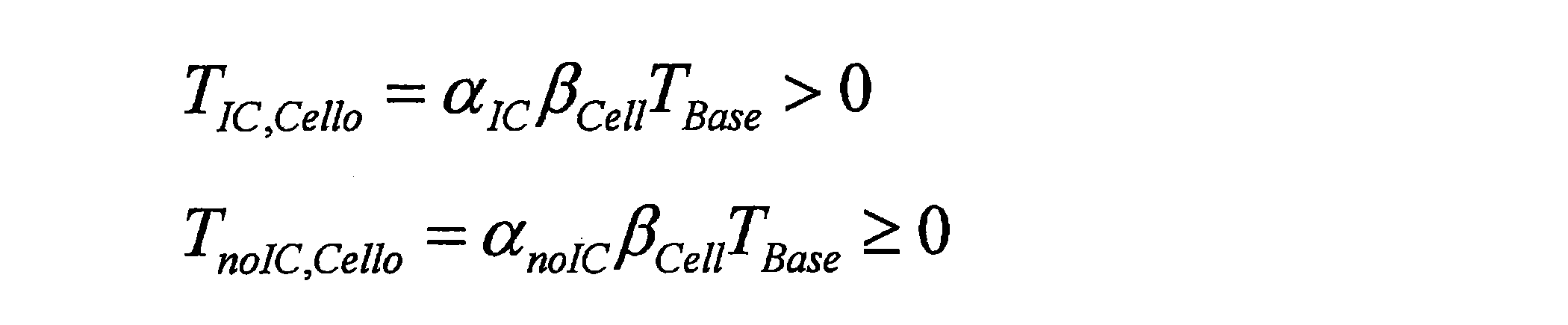
なお、スケーリングファクタは、例えば以下のような関係を有する。

なお、基地局100は、タイマ値そのものを送信する代わりに、ベースラインタイマ値TBaseと、スケーリングファクタとを送信してもよい。そして、端末装置200は、ベースラインタイマ値TBaseとスケーリングファクタとから、タイマ値を算出し、当該タイマ値に従って測定報告を行ってもよい。
(c)処理の流れ
図15~図17を参照して、タイマ値に従った測定報告に関する処理の例を説明する。
図15~図17を参照して、タイマ値に従った測定報告に関する処理の例を説明する。
(f―1)全体の処理
図15は、タイマ値に従った測定報告に関する全体の処理の概略的な流れの一例を示すシーケンス図である。
図15は、タイマ値に従った測定報告に関する全体の処理の概略的な流れの一例を示すシーケンス図である。
端末装置200は、ユーザ(即ち、端末装置200)の干渉除去のケイパビリティを基地局100に通知する(S481)。
基地局100は、上記ケイパビリティに基づいて、干渉除去に関連する上記ユーザ(即ち、端末装置200)のためのタイマ値を決定する(S483)。そして、基地局100は、当該タイマ値を端末装置200に通知する(S485)。
端末装置200は、セルについての測定を行う(S487)。そして、端末装置200は、上記セルについての測定報告をトリガするイベントの条件を判定する(S489)。
上記イベントが発生した場合に(即ち、上記条件が満たされる場合に)、端末装置200は、上記タイマ値に従って、基地局100への測定報告を行う(S491)。即ち、端末装置200は、上記タイマ値に従って、測定結果を基地局100に報告する。
なお、基地局100は、上記測定結果に基づいて、端末装置200のためのセルを選択してもよい。当該セルは、端末装置200のハンドオーバのターゲットセルであってもよい。即ち、基地局100は、上記測定結果に基づいて、端末装置200についてのハンドオーバ決定を行ってもよい。あるいは、上記セルは、端末装置200のためのセカンダリセルであってもよい。基地局100は、上記測定結果に基づいて、端末装置200のためのセカンダリセル(セカンダリコンポーネントキャリア)の追加又は削除を決定してもよい。
(f―2)端末装置の処理
-第1の例
図16は、ユーザオフセットに従った測定報告に関する端末装置200の処理の概略的な流れの第1の例を示すシーケンス図である。当該処理は、図15を参照して説明したステップS489及びS491に対応する。
-第1の例
図16は、ユーザオフセットに従った測定報告に関する端末装置200の処理の概略的な流れの第1の例を示すシーケンス図である。当該処理は、図15を参照して説明したステップS489及びS491に対応する。
端末装置200は、セルについての測定報告をトリガするイベントの条件を判定する(S501)。
イベント状態が変化した場合には(S503:YES)、端末装置200(制御部243)は、タイマをリスタートし(S511)、次の判定タイミングまで待機する(S513)。その後、処理はステップS501へ戻る。イベント状態の変化は、「Out-of-Event」から「In-Event」への変化であってもよく、「In-Event」から「Out-of-Event」への変化であってもよい。なお、「タイマをリスタートする」とは、タイマをリセットし、さらに当該タイマをスタートさせることを意味する。
イベント状態が変化していない場合には(S503:NO)、端末装置200(制御部243)は、タイマが既に開始しているかをチェックする(S505)。
タイマがまだ開始していない場合には(S505:NO)、タイマのエラーが発生したと考えられるので、端末装置200(制御部243)は、タイマをリスタートし(S511)、次の判定タイミングまで待機する(S513)。その後、処理はステップS501へ戻る。
タイマが既に開始している場合には(S505:YES)、端末装置200(制御部243)は、タイマが満了(expire)しているかチェックする(S507)。
タイマがまだ満了していない場合には(S507:NO)、端末装置200(制御部243)は、次の判定タイミングまで待機する(S513)。その後、処理はステップS501へ戻る。
タイマが満了している場合には(S507:YES)、端末装置200(制御部243)は、基地局100への測定報告を行う(S509)。その後、端末装置200(制御部243)は、タイマをリスタートし(S511)、次の判定タイミングまで待機する(S513)。その後、処理はステップS501へ戻る。
-第2の例
図17は、ユーザオフセットに従った測定報告に関する端末装置200の処理の概略的な流れの第2の例を示すシーケンス図である。当該処理は、図15を参照して説明したステップS489及びS491に対応する。とりわけ、第2の例では、イベント状態が「Out-of-Event」から「In-Event」への変化した場合に、測定報告が行われる。
図17は、ユーザオフセットに従った測定報告に関する端末装置200の処理の概略的な流れの第2の例を示すシーケンス図である。当該処理は、図15を参照して説明したステップS489及びS491に対応する。とりわけ、第2の例では、イベント状態が「Out-of-Event」から「In-Event」への変化した場合に、測定報告が行われる。
端末装置200は、セルについての測定報告をトリガするイベントの条件を判定する(S521)。
判定前のイベント状態が「Out-of-Event」である場合に(S523:YES)、イベント状態が「Out-of-Event」から「In-Event」になっていれば(S525:YES)、端末装置200(制御部243)は、タイマをスタートし(S527)、次の判定タイミングまで待機する(S529)。その後、処理はステップS521へ戻る。
イベント状態が「Out-of-Event」のまま維持されていれば(S525:NO)、端末装置200(制御部243)は、次の判定タイミングまで待機する(S529)。その後、処理はステップS521へ戻る。
判定前のイベント状態が「In-Event」である場合に(S523:NO)、イベント状態が「In-Event」から「Out-of-Event」になっていれば(S531:YES)、端末装置200(制御部243)は、タイマをリセットし(S539)、次の判定タイミングまで待機する(S529)。その後、処理はステップS521へ戻る。
イベント状態が「In-Event」のまま維持されていれば(S531:NO)、端末装置200(制御部243)は、タイマが既に開始しているかをチェックする(S533)。
タイマがまだ開始していない場合には(S533:NO)、タイマのエラーが発生したと考えられるので、端末装置200(制御部243)は、タイマをリスタートし(S541)、次の判定タイミングまで待機する(S529)。その後、処理はステップS521へ戻る。
タイマが既に開始している場合には(S533:YES)、端末装置200(制御部243)は、タイマが満了(expire)しているかチェックする(S535)。
タイマがまだ満了していない場合には(S535:NO)、端末装置200(制御部243)は、次の判定タイミングまで待機する(S529)。その後、処理はステップS521へ戻る。
タイマが満了している場合には(S535:YES)、端末装置200(制御部243)は、基地局100への測定報告を行う(S537)。その後、端末装置200(制御部243)は、タイマをリセットし(S539)、次の判定タイミングまで待機する(S529)。その後、処理はステップS521へ戻る。
例えば以上のように、ユーザのためのタイマ値に従ってセルが選択される。これにより、例えば、干渉除去を考慮した測定報告を行うことが可能になる。より具体的には、例えば、干渉除去が行われるか否かに応じて測定報告の頻度が調整される。
(5)第3の例(ユーザのための補正値に従った測定
上述したように、第3の例として、上記ユーザパラメータは、干渉除去に関連する上記ユーザ(即ち、端末装置200)のための補正値であって、通信品質の測定に用いられる上記補正値である。端末装置200(制御部243)は、上記補正値に従って、上記セルについての通信品質の測定を行う。
上述したように、第3の例として、上記ユーザパラメータは、干渉除去に関連する上記ユーザ(即ち、端末装置200)のための補正値であって、通信品質の測定に用いられる上記補正値である。端末装置200(制御部243)は、上記補正値に従って、上記セルについての通信品質の測定を行う。
(a)通信品質
例えば、上記通信品質は、SNRである。あるいは、上記通信品質は、SINR又はRSRQであってもよい。
例えば、上記通信品質は、SNRである。あるいは、上記通信品質は、SINR又はRSRQであってもよい。
(b)補正値
例えば、上記補正値は、上記ユーザの干渉除去のケイパビリティに応じて通信品質から干渉成分を差し引くための補正値である。
例えば、上記補正値は、上記ユーザの干渉除去のケイパビリティに応じて通信品質から干渉成分を差し引くための補正値である。
例えば、上記補正値は、上記ユーザ(即ち、端末装置200)の干渉除去のケイパビリティに応じた値である。具体的には、例えば、上記補正値は、上記ユーザが干渉除去のケイパビリティを有する場合により大きく、上記ユーザが干渉除去のケイパビリティを有しない場合により小さい。
(b-1)第1の例
第1の例として、以下のように、補正値を用いてセルについての通信品質(例えば、SNR)を算出することができる。
第1の例として、以下のように、補正値を用いてセルについての通信品質(例えば、SNR)を算出することができる。

上述した式では、干渉及び雑音に相当するRSSI/Nから、補正値C1が差し引かれる。例えば、端末装置200(即ち、ユーザ)が干渉除去のケイパビリティを有する場合には、補正値C1は正の値であり、端末装置200が干渉除去のケイパビリティを有しない場合には、補正値C1は0である。即ち、端末装置200が干渉除去のケイパビリティを有する場合には、干渉除去の結果として得られるより良好な通信品質が算出される。
なお、上述した式の左辺がSNRである例を説明したが、上述した式の左辺は、SNRの代わりに、SINRであってもよく、又はRSRQであってもよい。
(b-2)第2の例
第2の例として、以下のように、補正値を用いてセルについての通信品質(例えば、SNR)を算出することができる。
第2の例として、以下のように、補正値を用いてセルについての通信品質(例えば、SNR)を算出することができる。
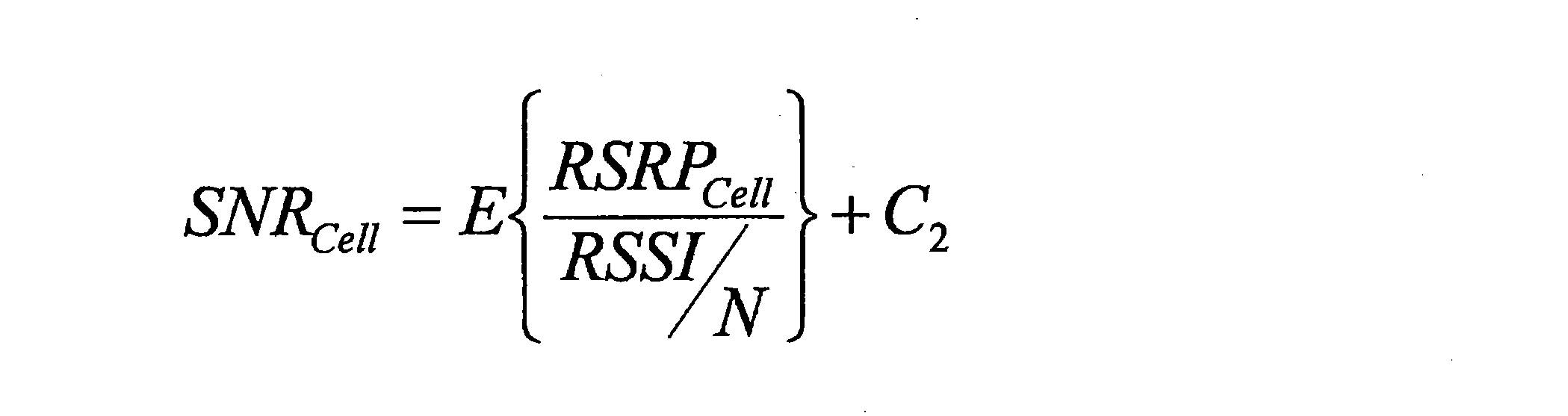
上述した式では、通常のRSRQに相当する値(右辺の第1項)に補正値C2が加算される。例えば、端末装置200(即ち、ユーザ)が干渉除去のケイパビリティを有する場合には、補正値C2は正の値であり、端末装置200が干渉除去のケイパビリティを有しない場合には、補正値C2は0である。即ち、端末装置200が干渉除去のケイパビリティを有する場合には、干渉除去の結果として得られるより良好な通信品質が算出される。補正値C2は、干渉除去による利得の増分に相当する。上述した式は、通常のRSRQを利用できるという利点をもつ。
なお、上述した式の左辺がSNRである例を説明したが、上述した式の左辺は、SNRの代わりに、SINRであってもよく、又はRSRQであってもよい。
(b-3)第3の例
第3の例として、以下のように、補正値を用いてセルについての通信品質(例えば、SNR)を算出することができる。
第3の例として、以下のように、補正値を用いてセルについての通信品質(例えば、SNR)を算出することができる。

上述した式では、干渉及び雑音に相当するRSSI/Nから、補正値C3が差し引かれる。とりわけこの例では、補正値C3は以下のように算出される。

上述した式において、NRS,Cellは、測定対象であるセルのチャネル帯域幅内でリファレンス信号が送信されるリソースエレメントの数であり、Ccellは、上記セルの測定の際に干渉除去の対象となる他のセル(以下、「除去対象セル」と呼ぶ)の集合である。即ち、補正値C3は、実際に除去されると期待される干渉の値である。よって、上述したSNRcellを算出するための式では、干渉及び雑音に相当するRSSI/Nから、実際に除去されと期待される干渉の値(即ち、補正値C3)が差し引かれる。
例えば、集合Ccellは、端末装置200(即ち、ユーザ)の干渉除去のケイパビリティに依存する。具体的には、例えば、除去対象セルの最大数は、端末装置200の干渉除去のケイパビリティに応じて決まり、集合Ccellは、当該最大数以下のセルを含む。そのため、端末装置200がより多くのセルからの干渉を除去できるほど、より良好な通信品質が算出され得る。なお、上記最大数よりもセルの数が多い場合には、より大きい受信電力をもたらすセルが、集合Ccellに含まれることが望ましい。より大きい受信電力を有する信号はより容易に除去されることが可能だからである。
なお、上述した式の左辺がSNRである例を説明したが、上述した式の左辺は、SNRの代わりに、SINRであってもよく、又はRSRQであってもよい。
例えば以上のように、第3の例では、上記補正値(即ち、上記ユーザの干渉除去のケイパビリティに応じて通信品質から干渉成分を差し引くための補正値)は、上記ユーザの干渉除去のケイパビリティに応じて選択される1つ以上の他のセルについての測定結果から算出される値である。例えば、上記1つ以上の他のセルは、上記ケイパビリティに応じた数の他のセルである。これにより、例えば、より実質的な通信品質の測定が可能になる。
(c)処理の流れ
図18~図20を参照して、補正値に従った測定に関する処理の例を説明する。
図18~図20を参照して、補正値に従った測定に関する処理の例を説明する。
(c―1)第1の例
図18は、補正値に従った測定に関する処理の概略的な流れの第1の例を示すシーケンス図である。この例は、例えば、上述した補正値の第1の例(C1)又は第2の例(C2)が用いられる場合の処理である。
図18は、補正値に従った測定に関する処理の概略的な流れの第1の例を示すシーケンス図である。この例は、例えば、上述した補正値の第1の例(C1)又は第2の例(C2)が用いられる場合の処理である。
端末装置200は、ユーザ(即ち、端末装置200)の干渉除去のケイパビリティを基地局100に通知する(S561)。
基地局100は、上記ケイパビリティに基づいて、干渉除去に関連する上記ユーザ(即ち、端末装置200)のための補正値を決定する(S563)。そして、基地局100は、当該補正値を端末装置200に通知する(S565)。
端末装置200は、上記補正値に従って、セルについての測定を行う(S567)。そして、端末装置200は、上記セルについての測定報告をトリガするイベントの条件を判定する(S569)。
上記イベントが発生した場合に(即ち、上記条件が満たされる場合に)、端末装置200は、基地局100への測定報告を行う(S571)。即ち、端末装置200は、測定結果を基地局100に報告する。
なお、基地局100は、上記測定結果に基づいて、端末装置200のためのセルを選択してもよい。当該セルは、端末装置200のハンドオーバのターゲットセルであってもよい。即ち、基地局100は、上記測定結果に基づいて、端末装置200についてのハンドオーバ決定を行ってもよい。あるいは、上記セルは、端末装置200のためのセカンダリセルであってもよい。基地局100は、上記測定結果に基づいて、端末装置200のためのセカンダリセル(セカンダリコンポーネントキャリア)の追加又は削除を決定してもよい。
(c―2)第2の例
図19は、補正値に従った測定に関する処理の概略的な流れの第2の例を示すシーケンス図である。この例は、例えば、上述した補正値の第3の例(C3)が用いられる場合の処理であり、端末装置200が除去対象セルの集合を決定する。
図19は、補正値に従った測定に関する処理の概略的な流れの第2の例を示すシーケンス図である。この例は、例えば、上述した補正値の第3の例(C3)が用いられる場合の処理であり、端末装置200が除去対象セルの集合を決定する。
端末装置200は、ユーザ(即ち、端末装置200)の干渉除去のケイパビリティ及び測定結果に基づいて、除去対象セルの集合を決定する(S581)。さらに、端末装置200は、当該集合に基づいて、干渉除去に関連する上記ユーザ(即ち、端末装置200)のための補正値を決定する(S583)。
端末装置200は、上記補正値に従って、セルについての測定を行う(S585)。そして、端末装置200は、上記セルについての測定報告をトリガするイベントの条件を判定する(S587)。
上記イベントが発生した場合に(即ち、上記条件が満たされる場合に)、端末装置200は、基地局100への測定報告を行う(S589)。即ち、端末装置200は、測定結果を基地局100に報告する。
なお、基地局100は、上記測定結果に基づいて、端末装置200のためのセルを選択してもよい。当該セルは、端末装置200のハンドオーバのターゲットセルであってもよい。即ち、基地局100は、上記測定結果に基づいて、端末装置200についてのハンドオーバ決定を行ってもよい。あるいは、上記セルは、端末装置200のためのセカンダリセルであってもよい。基地局100は、上記測定結果に基づいて、端末装置200のためのセカンダリセル(セカンダリコンポーネントキャリア)の追加又は削除を決定してもよい。
(c―3)第3の例
図20は、補正値に従った測定に関する処理の概略的な流れの第3の例を示すシーケンス図である。この例は、例えば、上述した補正値の第3の例(C3)が用いられる場合の処理であり、基地局100が除去対象セルの集合を決定する。
図20は、補正値に従った測定に関する処理の概略的な流れの第3の例を示すシーケンス図である。この例は、例えば、上述した補正値の第3の例(C3)が用いられる場合の処理であり、基地局100が除去対象セルの集合を決定する。
端末装置200は、ユーザ(即ち、端末装置200)の干渉除去のケイパビリティを基地局100に通知する(S601)。
端末装置200は、セルについての測定を行う(S603)。そして、端末装置200は、上記セルについての測定報告をトリガするイベントの条件を判定する(S605)。
上記イベントが発生した場合に(即ち、上記条件が満たされる場合に)、端末装置200は、基地局100への測定報告を行う(S607)。即ち、端末装置200は、測定結果を基地局100に報告する。
基地局100は、上記ケイパビリティ及び上記測定結果に基づいて、除去対象セルの集合を決定する(S609)。そして、基地局100は、当該集合を端末装置200に通知する(S611)。基地局100は、周辺セルの基地局にも、上記集合を通知してもよく、これにより、上記集合がセル間で共有されてもよい。
端末装置200は、上記集合に基づいて、干渉除去に関連する上記ユーザ(即ち、端末装置200)のための補正値を決定する(S613)。
端末装置200は、上記補正値に従って、セルについての測定を行う(S615)。そして、端末装置200は、上記セルについての測定報告をトリガするイベントの条件を判定する(S617)。
上記イベントが発生した場合に(即ち、上記条件が満たされる場合に)、端末装置200は、基地局100への測定報告を行う(S619)。即ち、端末装置200は、測定結果を基地局100に報告する。
なお、基地局100は、上記測定結果に基づいて、端末装置200のためのセルを選択してもよい。当該セルは、端末装置200のハンドオーバのターゲットセルであってもよい。即ち、基地局100は、上記測定結果に基づいて、端末装置200についてのハンドオーバ決定を行ってもよい。あるいは、上記セルは、端末装置200のためのセカンダリセルであってもよい。基地局100は、上記測定結果に基づいて、端末装置200のためのセカンダリセル(セカンダリコンポーネントキャリア)の追加又は削除を決定してもよい。
例えば以上のように、基地局100が、除去対象セルの集合を決定してもよい。なお、基地局100の代わりに、他のノード(例えば、コアネットワークノードなど)が、除去対象セルの集合を決定してもよい。
(c-4)除去対象セルの集合の決定
図21は、除去対象セルの集合の決定のための処理の概略的な流れの一例を示すシーケンス図である。当該処理は、端末装置200により実行され、図19を参照して説明したステップS581に対応する。
図21は、除去対象セルの集合の決定のための処理の概略的な流れの一例を示すシーケンス図である。当該処理は、端末装置200により実行され、図19を参照して説明したステップS581に対応する。
端末装置200は、セルごとのRSRPを取得する(S621)。そして、端末装置200は、より大きいRSRPをもたらすM+1個のセルを選択する(S623)。Mは、端末装置200の干渉除去のケイパビリティに応じた、除去対象セルの最大数である。
選択されたM+1個のセルの中に、測定対象であるセルが含まれる場合には(S625:YES)、端末装置200は、選択されたM+1個のセルのうちの、測定対象のセル以外のセルを、除去対象セルの集合として決定する(S627)。そして、処理は終了する。
選択されたM+1個のセルの中に、測定対象であるセルが含まれない場合には(S625:NO)、端末装置200は、選択されたM+1個のセルのうちの、最小のRSRPをもたらすセル以外のセルを、除去対象セルの集合として決定する(S629)。そして、処理は終了する。
なお、上記処理は、端末装置200の代わりに基地局100により実行されてもよい。この場合に、上記処理は、図20を参照して説明したステップS609に対応してもよい。
(d)変形例
上述した例では、端末装置200が、補正値に従って、セルについての測定を行う。しかしながら、本開示の実施形態は係る例に限定されない。変形例として、基地局100が、補正値に従って、セルについての測定を行ってもよい。
上述した例では、端末装置200が、補正値に従って、セルについての測定を行う。しかしながら、本開示の実施形態は係る例に限定されない。変形例として、基地局100が、補正値に従って、セルについての測定を行ってもよい。
例えば、情報取得部151は、干渉除去に関連する上記ユーザ(即ち、端末装置200)のための補正値であって、通信品質の測定に用いられる上記補正値を取得する。そして、制御部153は、上記補正値に従って、上記セルについての通信品質の測定を行う。
より具体的には、例えば、端末装置200は、ユーザ(即ち、端末装置200)の干渉除去のケイパビリティを基地局100に通知し、基地局100(処理部150)は、当該ケイパビリティに基づいて、干渉除去に関連する上記ユーザの補正値を決定する。そして、基地局100(情報取得部151)は、上記補正値を取得し、基地局100(制御部153)は、上記補正値と、端末装置200により報告される測定結果とから、新たな測定結果を算出する。例えばこのように、基地局100が、通信品質の測定を行う。
(d-1)処理の流れ(第4の例)
図22は、補正値に従った測定に関する処理の概略的な流れの第4の例を示すシーケンス図である。この例は、例えば、上述した補正値の第1の例(C1)又は第2の例(C2)が用いられる場合の処理である。
図22は、補正値に従った測定に関する処理の概略的な流れの第4の例を示すシーケンス図である。この例は、例えば、上述した補正値の第1の例(C1)又は第2の例(C2)が用いられる場合の処理である。
端末装置200は、ユーザ(即ち、端末装置200)の干渉除去のケイパビリティを基地局100に通知する(S641)。
基地局100は、上記ケイパビリティに基づいて、干渉除去に関連する上記ユーザ(即ち、端末装置200)のための補正値を決定する(S643)。
端末装置200は、セルについての測定を行う(S645)。そして、端末装置200は、上記セルについての測定報告をトリガするイベントの条件を判定する(S647)。
上記イベントが発生した場合に(即ち、上記条件が満たされる場合に)、端末装置200は、基地局100への測定報告を行う(S649)。即ち、端末装置200は、測定結果を基地局100に報告する。
基地局100は、上記補正値に従って、上記セルについての測定を行う(S651)。例えば、基地局100は、上記補正値と、上記測定結果とから、新たな測定結果を算出する。
なお、基地局100は、上記新たな測定結果に基づいて、端末装置200のためのセルを選択してもよい。当該セルは、端末装置200のハンドオーバのターゲットセルであってもよい。即ち、基地局100は、上記新たな測定結果に基づいて、端末装置200についてのハンドオーバ決定を行ってもよい。あるいは、上記セルは、端末装置200のためのセカンダリセルであってもよい。基地局100は、上記新たな測定結果に基づいて、端末装置200のためのセカンダリセル(セカンダリコンポーネントキャリア)の追加又は削除を決定してもよい。
(d-2)処理の流れ(第5の例)
図23は、補正値に従った測定に関する処理の概略的な流れの第5の例を示すシーケンス図である。この例は、例えば、上述した補正値の第3の例(C3)が用いられる場合の処理である。
図23は、補正値に従った測定に関する処理の概略的な流れの第5の例を示すシーケンス図である。この例は、例えば、上述した補正値の第3の例(C3)が用いられる場合の処理である。
端末装置200は、ユーザ(即ち、端末装置200)の干渉除去のケイパビリティを基地局100に通知する(S661)。
端末装置200は、セルについての測定を行う(S663)。そして、端末装置200は、上記セルについての測定報告をトリガするイベントの条件を判定する(S665)。
上記イベントが発生した場合に(即ち、上記条件が満たされる場合に)、端末装置200は、基地局100への測定報告を行う(S667)。即ち、端末装置200は、測定結果を基地局100に報告する。
基地局100は、上記ケイパビリティ及び上記測定結果に基づいて、除去対象セルの集合を決定する(S669)。基地局100は、端末装置200及び/又は周辺セルの基地局に上記集合を通知してもよい。
さらに、基地局100は、当該集合に基づいて、干渉除去に関連する上記ユーザ(即ち、端末装置200)のための補正値を決定する(S671)。
基地局100は、上記補正値に従って、上記セルについての測定を行う(S673)。例えば、基地局100は、上記補正値と、上記測定結果とから、新たな測定結果を算出する。
なお、基地局100は、上記新たな測定結果に基づいて、端末装置200のためのセルを選択してもよい。当該セルは、端末装置200のハンドオーバのターゲットセルであってもよい。即ち、基地局100は、上記新たな測定結果に基づいて、端末装置200についてのハンドオーバ決定を行ってもよい。あるいは、上記セルは、端末装置200のためのセカンダリセルであってもよい。基地局100は、上記新たな測定結果に基づいて、端末装置200のためのセカンダリセル(セカンダリコンポーネントキャリア)の追加又は削除を決定してもよい。
例えば以上のように、基地局100が、補正値に従ってセルについての測定を行ってもよい。なお、基地局100の代わりに、他のノード(例えば、コアネットワークノードなど)が、補正値に従ってセルについての測定を行ってもよい。
例えば以上のように、補正値に従って測定が行われる。これにより、例えば、干渉除去を考慮した測定を行うことが可能になる。より具体的には、例えば、干渉除去が行われるか否かに応じて通信品質が算出される。そのため、より実質的な通信品質に基づいて、測定報告、ハンドオーバ及び/又はセカンダリセルの追加/削除などが行われ得る。
<4.2.セル間干渉制御>
(1)前提となる考え方
上述したようなユーザパラメータ(例えば、ユーザオフセット、タイマ値又は補正値)に従って測定又は測定報告が行われる場合には、上記ユーザパラメータを考慮してセル間干渉制御(ICIC)を行うことにより、より良好な通信品質が得られ得る。とりわけHetNetのケースにおいてより良好な通信品質が得られると考えられる。
(1)前提となる考え方
上述したようなユーザパラメータ(例えば、ユーザオフセット、タイマ値又は補正値)に従って測定又は測定報告が行われる場合には、上記ユーザパラメータを考慮してセル間干渉制御(ICIC)を行うことにより、より良好な通信品質が得られ得る。とりわけHetNetのケースにおいてより良好な通信品質が得られると考えられる。
例えば、図5を再び参照すると、この例では、基地局100は、マクロセルの基地局であり、例えば、端末装置200のサービングセルは、マクロセルであるセル101である。例えば、マクロセルであるセル101とスモールセル21とにおいて、同一の周波数帯域(例えば、コンポーネントキャリア)が使用される。この場合に、ダウンリンクにおいて、端末装置200は、基地局100により送信される所望信号に加えて、基地局20により送信される信号(即ち、干渉信号)を受信し得る。
例えば、図6を再び参照すると、この例では、基地局100は、スモールセルの基地局であり、例えば、端末装置200のサービングセルは、スモールセルであるセル101である。例えば、スモールセルであるセル101とマクロセル31とにおいて、同一の周波数帯域(例えば、コンポーネントキャリア)が使用される。この場合に、ダウンリンクにおいて、端末装置200は、基地局100により送信される所望信号に加えて、基地局30により送信される信号(即ち、干渉信号)を受信し得る。
上述したようなHetNetでは、スモールセルの送信電力よりも、マクロセルの送信電力の方が大きい。そのため、スモールセルからマクロセルへの干渉よりも、マクロセルからスモールセルへの干渉の方が、より重大であると言える。これは、干渉除去のケイパビリティを有するユーザのみではなく、干渉除去のケイパビリティを有しないユーザにもあてはまる。このような干渉を軽減するために、ICICが求められる。ICICは、例えば、セル間で別々の無線リソース(例えば、リソースブロック、サブフレーム、又はコンポーネントキャリアなど)を使用すること、又は、セル間で送信電力を調整することなどである。
端末装置200は、干渉除去のケイパビリティを有する場合には、大きい受信電力を有する信号を干渉として除去し得る。よって、干渉除去のケイパビリティを有するユーザと、干渉除去のケイパビリティを有しないユーザとの間で、ICICの適用の方針が異なることが望ましいと考えられる。
周辺セルからの干渉は、セルの選択手法に依存し得る。より具体的には、例えば、周辺セルからの干渉は、ユーザオフセットに依存し得る。例えば、サービングセルについてのユーザオフセットが大きい場合には、サービングセルがより選択されやすくなっており、多少悪い環境であってもサービングセルが選択されている可能性がある。一方、サービングセルについてのユーザオフセットが小さい場合には、サービングセルがより選択されにくくなっており、良好な環境でサービングセルが選択されていると考えられる。そのため、ユーザオフセットによって、ICICの適用の方針が異なることが望ましいと考えられる。
(2)ユーザオフセットに基づくセル間干渉制御の判定
例えば、基地局100(情報取得部151)は、干渉除去に関連するユーザ(端末装置200)のためのオフセットであって、測定報告をトリガするイベントの条件に含まれる当該オフセット(即ち、ユーザオフセット)を取得する。そして、基地局100(制御部153)は、当該オフセットに基づいて、上記ユーザのためのセル間干渉制御(Inter-Cell Interference Coordination:ICIC)を行うかを判定する。なお、基地局100は、上記ユーザのためのセル間干渉制御を行うと判定する場合には、当該セル間干渉制御を行う。
例えば、基地局100(情報取得部151)は、干渉除去に関連するユーザ(端末装置200)のためのオフセットであって、測定報告をトリガするイベントの条件に含まれる当該オフセット(即ち、ユーザオフセット)を取得する。そして、基地局100(制御部153)は、当該オフセットに基づいて、上記ユーザのためのセル間干渉制御(Inter-Cell Interference Coordination:ICIC)を行うかを判定する。なお、基地局100は、上記ユーザのためのセル間干渉制御を行うと判定する場合には、当該セル間干渉制御を行う。
(a)オフセット
上記ユーザオフセットの具体的な説明は、上述したとおりである。
上記ユーザオフセットの具体的な説明は、上述したとおりである。
とりわけ、例えば、上記ユーザオフセットは、上記ユーザ(即ち、端末装置200)のサービングセルについてのオフセットと、周辺セルについてのオフセットとを含む。即ち、基地局100(制御部153)は、上記ユーザのサービングセルのオフセットと、周辺セルのオフセットとに基づいて、上記ユーザのためのセル間干渉制御を行うかを判定する。なお、上記サービングセルは、上記ユーザ(即ち、端末装置200)のプライマリセルであってもよい。
(b)ケイパビリティ
例えば、基地局100(制御部153)は、上記ユーザ(即ち、端末装置200)の干渉除去のケイパビリティにさらに基づいて、上記ユーザのためのセル間干渉制御(ICIC)を行うかを判定する。
例えば、基地局100(制御部153)は、上記ユーザ(即ち、端末装置200)の干渉除去のケイパビリティにさらに基づいて、上記ユーザのためのセル間干渉制御(ICIC)を行うかを判定する。
(c)判定の例
(c-1)サービングセルがマクロセルであるケース
第1の例として、図5の例に示されるように、基地局100は、マクロセルの基地局であり、端末装置200のサービングセルは、マクロセルであるセル101である。以下、図24を参照してこのケースにおける判定の例を説明する。
(c-1)サービングセルがマクロセルであるケース
第1の例として、図5の例に示されるように、基地局100は、マクロセルの基地局であり、端末装置200のサービングセルは、マクロセルであるセル101である。以下、図24を参照してこのケースにおける判定の例を説明する。
図24は、ユーザのサービングセルがマクロセルであるケースにおける判定の例を説明するための説明図である。
例えば、ユーザ(即ち、端末装置200)のサービングセルがマクロセルである場合には、干渉(即ち、スモールセルからの干渉)は小さいのでICICは不要であり、基地局100は、ICICを行わないと判定する。
以下のように、サービングセル(例えば、プライマリセル)のユーザオフセットOupが、周辺セルのユーザオフセットOunよりも大きい場合がある。

この場合に、サービングセルの信号(所望信号)の受信電力よりも、周辺セルの信号(干渉信号)の受信電力の方が、大きい可能性がある。そのため、例えば、端末装置200が干渉除去のケイパビリティを有する場合には、ユーザ(即ち、端末装置200)側での干渉除去が行われ得る。
なお、オフセットの大小関係について、以下のように、ユーザオフセットのみではなく、周波数オフセットOf及びセルオフセットOcも考慮されてもよい。

さらに、以下のようにヒステリシスも考慮されてもよい。

(c-2)サービングセルがスモールセルであるケース
第2の例として、図6の例に示されるように、基地局100は、スモールセルの基地局であり、端末装置200のサービングセルは、スモールセルであるセル101である。以下、図25を参照してこのケースにおける判定の例を説明する。
第2の例として、図6の例に示されるように、基地局100は、スモールセルの基地局であり、端末装置200のサービングセルは、スモールセルであるセル101である。以下、図25を参照してこのケースにおける判定の例を説明する。
図25は、ユーザのサービングセルがスモールセルであるケースにおける判定の例を説明するための説明図である。
例えば、ユーザ(即ち、端末装置200)のサービングセルがスモールセルである場合には、干渉(即ち、マクロセルからの干渉)が大きい可能性があるので、ICICが必要になり得る。例えば、とりわけ、サービングセル(例えば、プライマリセル)のユーザオフセットOupが、周辺セルのユーザオフセットOnpよりも大きい場合に、多少悪い環境であってもサービングセルが選択されている可能性がある。よって、この場合に、端末装置200が、干渉除去のケイパビリティを有しなければ、基地局100は、端末装置200のためのICICを行うと判定する。その結果、例えば、ICICが行われる。一例として、端末装置200には、周辺セルで使用されない無線リソース(例えば、リソースブロック)が割り当てられる。別の例として、端末装置200に割り当てられる無線リソースについて、サービングセルと周辺セルとの間で送信電力が調整される。
なお、端末装置200が、干渉除去のケイパビリティを有する場合には、ユーザ(即ち、端末装置200)側での干渉除去が行われ得る。
(d)変形例
変形例として、基地局100(制御部153)は、上記ユーザ(即ち、端末装置200)により報告される測定結果にさらに基づいて、上記ユーザのためのセル間干渉制御を行うかを判定してもよい。
変形例として、基地局100(制御部153)は、上記ユーザ(即ち、端末装置200)により報告される測定結果にさらに基づいて、上記ユーザのためのセル間干渉制御を行うかを判定してもよい。
(d-1)測定結果
-受信電力
上記測定結果は、受信電力の測定結果であってもよい。当該受信電力は、RSRPであってもよく、他の電力であってもよい。
-受信電力
上記測定結果は、受信電力の測定結果であってもよい。当該受信電力は、RSRPであってもよく、他の電力であってもよい。
-サービングセル及び周辺セルについての測定結果
上記測定結果は、上記ユーザのサービングセルについての測定結果と、周辺セルについての測定結果とを含んでもよい。即ち、基地局100は、上記サービングセルについての測定結果と上記周辺セルについての測定結果とにさらに基づいて、上記ユーザのためのセル間干渉制御を行うかを判定してもよい。
上記測定結果は、上記ユーザのサービングセルについての測定結果と、周辺セルについての測定結果とを含んでもよい。即ち、基地局100は、上記サービングセルについての測定結果と上記周辺セルについての測定結果とにさらに基づいて、上記ユーザのためのセル間干渉制御を行うかを判定してもよい。
より具体的には、基地局100は、上記サービングセルについての測定結果(例えば、受信電力)と上記周辺セルについての測定結果(例えば、受信電力)との差分に基づいて、上記ユーザのためのセル間干渉制御を行うかを判定してもよい。
-受信電力差分
以下のように、サービングセルについての受信電力Psと、周辺セルについての受信電力Pnとの差分(以下、受信電力差分)を、Pdiffと表す。
以下のように、サービングセルについての受信電力Psと、周辺セルについての受信電力Pnとの差分(以下、受信電力差分)を、Pdiffと表す。

(d-2)オフセット差分
サービングセル(例えば、プライマリセル)についての総オフセットOp,totalは、以下のように表される。
サービングセル(例えば、プライマリセル)についての総オフセットOp,totalは、以下のように表される。

周辺セルについての総オフセットOn,totalは、以下のように表される(なお、ヒステリシスは含まれなくてもよい)。

以下のように、サービングセル(例えば、プライマリセル)についての総オフセットOp,totalと、周辺セルについての総オフセットOn,totalとの差分(以下、「総オフセット差分」と呼ぶ)を、Odiffと表す。

なお、以下では、上記総オフセット差分Odiffが用いられる例を説明するが、変形例は係る例に限定されない。例えば、総オフセット差分Odiffの代わりに、サービングセル(例えば、プライマリセル)についてのユーザオフセットOupと、周辺セルについてのユーザオフセットOunとの差分が、用いられてもよい。
(d-3)判定の例
-第1の例
図26は、変形例に係る判定の第1の例を説明するための説明図である。
-第1の例
図26は、変形例に係る判定の第1の例を説明するための説明図である。
例えば、総オフセット差分Odiffが受信電力差分Pdiffよりも小さい場合には、オフセットの差分がなくても、周辺セルではなくサービングセルが選択される程度に、サービングセルが良好である。よって、この場合に、基地局100は、端末装置200のためのICICを行わないと判定してもよい。
一方、総オフセット差分Odiffが受信電力差分Pdiffよりも大きい場合には、オフセットの差分のおかげで、周辺セルではなくサービングセルが選択されている。即ち、周辺セルに比べてサービングセルは良好ではないと言える。よって、端末装置200(即ち、ユーザ)が、干渉除去のケイパビリティを有しない場合には、基地局100は、端末装置200のためのICICを行うと判定してもよい。端末装置200(即ち、ユーザ)が、干渉除去のケイパビリティを有する場合には、端末装置200側での干渉除去が行われるので、基地局100は、端末装置200のためのICICを行わないと判定してもよい。
-第2の例
図27は、変形例に係る判定の第2の例を説明するための説明図である。この例では、いずれの総オフセット差分は考慮されず、受信電力差分のみが考慮される。
図27は、変形例に係る判定の第2の例を説明するための説明図である。この例では、いずれの総オフセット差分は考慮されず、受信電力差分のみが考慮される。
例えば、受信電力差分Pdiffが0よりも大きい場合には、周辺セルと比べてサービングセルが良好である。よって、この場合に、基地局100は、端末装置200のためのICICを行わないと判定してもよい。
一方、受信電力差分Pdiffが0よりも小さい場合には、周辺セルと比べてサービングセルが良好ではなく、オフセットの差分のおかげで、周辺セルではなくサービングセルが選択されていると言える。よって、端末装置200(即ち、ユーザ)が、干渉除去のケイパビリティを有しない場合には、基地局100は、端末装置200のためのICICを行うと判定してもよい。端末装置200(即ち、ユーザ)が、干渉除去のケイパビリティを有する場合には、端末装置200側での干渉除去が行われるので、基地局100は、端末装置200のためのICICを行わないと判定してもよい。
(e)全ての周辺セルについての干渉を除去できないケース
なお、図24~図27の例では、端末装置200(即ち、ユーザ)が、干渉除去のケイパビリティを有する場合には、セル間干渉制御(ICIC)が行われず、端末装置200側での干渉除去が行われる。しかしながら、本開示の実施形態は係る例に限定されない。
なお、図24~図27の例では、端末装置200(即ち、ユーザ)が、干渉除去のケイパビリティを有する場合には、セル間干渉制御(ICIC)が行われず、端末装置200側での干渉除去が行われる。しかしながら、本開示の実施形態は係る例に限定されない。
例えば、端末装置200が干渉を除去できるセルの最大数が、干渉が除去されるべき周辺セルの数よりも小さくなり得る。この場合に、上記最大数の周辺セルについては、干渉除去が行われ、残りの周辺セルについては、ICICが行われてもよい。即ち、端末装置200が、干渉除去のケイパビリティを有する場合でも、基地局100は、端末装置200のためのICICを行うと判定してもよい。
以上のように、セル間干渉制御の判定が行われる。これにより、例えば、端末装置200のサービングセルと周辺セルとの間での干渉を抑えることが可能になる。
(3)基地局間での情報の交換
上述したように、例えば、基地局100(制御部153)は、端末装置200のためのICICを行うと判定する。この場合に、基地局100(制御部153)は、端末装置200のためのICICを行う。例えば、基地局100(制御部153)は、ICICの動作として、周辺セルの基地局との間で情報を交換する。
上述したように、例えば、基地局100(制御部153)は、端末装置200のためのICICを行うと判定する。この場合に、基地局100(制御部153)は、端末装置200のためのICICを行う。例えば、基地局100(制御部153)は、ICICの動作として、周辺セルの基地局との間で情報を交換する。
(a)周辺基地局への情報の提供
例えば、基地局100は、端末装置200(即ち、ユーザ)についてのICICを行うと判定する場合に、端末装置200についての情報を、周辺セルの基地局(以下、「周辺基地局」と呼ぶ)に提供する。例えば、基地局100は、周辺基地局にICICを要求し、この要求の際に、端末装置200についての情報を提供する。
例えば、基地局100は、端末装置200(即ち、ユーザ)についてのICICを行うと判定する場合に、端末装置200についての情報を、周辺セルの基地局(以下、「周辺基地局」と呼ぶ)に提供する。例えば、基地局100は、周辺基地局にICICを要求し、この要求の際に、端末装置200についての情報を提供する。
例えば、上記周辺基地局に提供される上記情報は、ユーザID、干渉除去のケイパビリティ(例えば、干渉除去のタイプの有無又はタイプなど)、サービングセル(即ち、セル101)と上記周辺セルとの間の受信電力の差分、サービングセル(即ち、セル101)と上記周辺セルとの間のオフセットの差分、並びに、サービングセルのID及びサービングセルでの送信電力などを含む。以下、図28を参照して、周辺基地局に提供される上記情報の具体例を説明する。
図28は、ICICのために周辺基地局に提供される情報の例を説明するための説明図である。図28を参照すると、基地局100が周辺基地局に提供する情報が示されている。例えば、基地局100は、ICICの対象となるユーザの数、及び各ユーザについての情報を提供する。各ユーザについての情報は、ユーザID、干渉除去のケイパビリティ、受信電力差分、オフセット差分、並びに、サービングセルのID及び送信電力を含む。
このような情報の提供により、例えば、基地局100と周辺セルの基地局との間でのICICの実行の判定、及び/又は当該ICICの実行が可能になる。
(b)周辺基地局からの応答
例えば、上記周辺基地局は、基地局100からの情報の提供(例えばICICの要求)に応じて、ICICが可能かを判定し、基地局100に応答する。この際に、例えば、上記周辺基地局は、使用する無線リソースと当該無線リソースについての送信電力とを示す情報を、基地局100に提供する。以下、図29を参照して、周辺基地局により提供される上記情報の具体例を説明する。
例えば、上記周辺基地局は、基地局100からの情報の提供(例えばICICの要求)に応じて、ICICが可能かを判定し、基地局100に応答する。この際に、例えば、上記周辺基地局は、使用する無線リソースと当該無線リソースについての送信電力とを示す情報を、基地局100に提供する。以下、図29を参照して、周辺基地局により提供される上記情報の具体例を説明する。
図29は、ICICのために周辺基地局により提供される情報の例を説明するための説明図である。図29を参照すると、周辺基地局により提供される情報が示されている。例えば、周辺基地局は、コンポーネントキャリアの数、及びコンポーネントキャリアごとの情報を提供する。コンポーネントキャリアごとの当該情報は、セルIDと、サブフレームごとの情報とを含む。サブフレームごとの当該情報は、周辺セルで使用されるリソースブロック(例えば、リソースブロックID)と、当該リソースブロックについての送信電力とを示す。
このような情報の提供により、例えば、基地局100は、周辺セルとの干渉を回避しつつ端末装置200に無線リソースを割り当てることが可能になる。即ち、ICICが実現される。
(4)処理の流れ
図30は、セル間干渉制御(ICIC)に関する処理の概略的な流れの一例を示すシーケンス図である。
図30は、セル間干渉制御(ICIC)に関する処理の概略的な流れの一例を示すシーケンス図である。
端末装置200は、ユーザ(即ち、端末装置200)の干渉除去のケイパビリティを基地局100に通知する(S681)。
基地局100は、上記ケイパビリティに基づいて、干渉除去に関連する上記ユーザ(即ち、端末装置200)のためのオフセット(即ち、ユーザオフセット)を決定する(S683)。そして、基地局100は、当該ユーザオフセットを端末装置200に通知する(S685)。
端末装置200は、セルについての測定を行う(S687)。そして、端末装置200は、上記ユーザオフセットに従って、上記セルについての測定報告をトリガするイベントの条件を判定する(S689)。
上記イベントが発生した場合に(即ち、上記条件が満たされる場合に)、端末装置200は、基地局100への測定報告を行う(S691)。即ち、端末装置200は、測定結果を基地局100に報告する。
基地局100は、上記ユーザオフセット(及び上記測定結果)に基づいて、上記ユーザ(即ち、端末装置200)のためのセル間干渉制御(ICIC)を行うかを判定する(S693)。
基地局100は、ICICを行うと判定する場合に、周辺基地局(周辺セルの基地局)にICICを要求する(S695)。
上記周辺基地局は、基地局100からの要求に応じて、ICICを行うかを判定し(S697)、基地局100へ応答する(S699)。
その後、基地局100は、スケジューリングを行う(S701)。即ち、基地局100は、上記周辺セルとの干渉が回避されるように、端末装置200に無線リソースを割り当てる。
<<5.応用例>>
本開示に係る技術は、様々な製品へ応用可能である。例えば、基地局100は、マクロeNB又はスモールeNBなどのいずれかの種類のeNB(evolved Node B)として実現されてもよい。スモールeNBは、ピコeNB、マイクロeNB又はホーム(フェムト)eNBなどの、マクロセルよりも小さいセルをカバーするeNBであってよい。その代わりに、基地局100は、NodeB又はBTS(Base Transceiver Station)などの他の種類の基地局として実現されてもよい。基地局100は、無線通信を制御する本体(基地局装置ともいう)と、本体とは別の場所に配置される1つ以上のRRH(Remote Radio Head)とを含んでもよい。また、後述する様々な種類の端末が一時的に又は半永続的に基地局機能を実行することにより、基地局100として動作してもよい。さらに、基地局100の少なくとも一部の構成要素は、基地局装置又は基地局装置のためのモジュールにおいて実現されてもよい。
本開示に係る技術は、様々な製品へ応用可能である。例えば、基地局100は、マクロeNB又はスモールeNBなどのいずれかの種類のeNB(evolved Node B)として実現されてもよい。スモールeNBは、ピコeNB、マイクロeNB又はホーム(フェムト)eNBなどの、マクロセルよりも小さいセルをカバーするeNBであってよい。その代わりに、基地局100は、NodeB又はBTS(Base Transceiver Station)などの他の種類の基地局として実現されてもよい。基地局100は、無線通信を制御する本体(基地局装置ともいう)と、本体とは別の場所に配置される1つ以上のRRH(Remote Radio Head)とを含んでもよい。また、後述する様々な種類の端末が一時的に又は半永続的に基地局機能を実行することにより、基地局100として動作してもよい。さらに、基地局100の少なくとも一部の構成要素は、基地局装置又は基地局装置のためのモジュールにおいて実現されてもよい。
また、例えば、端末装置200は、スマートフォン、タブレットPC(Personal Computer)、ノートPC、携帯型ゲーム端末、携帯型/ドングル型のモバイルルータ若しくはデジタルカメラなどのモバイル端末、又はカーナビゲーション装置などの車載端末として実現されてもよい。また、端末装置200は、M2M(Machine To Machine)通信を行う端末(MTC(Machine Type Communication)端末ともいう)として実現されてもよい。さらに、端末装置200の少なくとも一部の構成要素は、これら端末に搭載されるモジュール(例えば、1つのダイで構成される集積回路モジュール)において実現されてもよい。
<5.1.基地局に関する応用例>
(第1の応用例)
図31は、本開示に係る技術が適用され得るeNBの概略的な構成の第1の例を示すブロック図である。eNB800は、1つ以上のアンテナ810、及び基地局装置820を有する。各アンテナ810及び基地局装置820は、RFケーブルを介して互いに接続され得る。
(第1の応用例)
図31は、本開示に係る技術が適用され得るeNBの概略的な構成の第1の例を示すブロック図である。eNB800は、1つ以上のアンテナ810、及び基地局装置820を有する。各アンテナ810及び基地局装置820は、RFケーブルを介して互いに接続され得る。
アンテナ810の各々は、単一の又は複数のアンテナ素子(例えば、MIMOアンテナを構成する複数のアンテナ素子)を有し、基地局装置820による無線信号の送受信のために使用される。eNB800は、図31に示したように複数のアンテナ810を有し、複数のアンテナ810は、例えばeNB800が使用する複数の周波数帯域にそれぞれ対応してもよい。なお、図31にはeNB800が複数のアンテナ810を有する例を示したが、eNB800は単一のアンテナ810を有してもよい。
基地局装置820は、コントローラ821、メモリ822、ネットワークインタフェース823及び無線通信インタフェース825を備える。
コントローラ821は、例えばCPU又はDSPであってよく、基地局装置820の上位レイヤの様々な機能を動作させる。例えば、コントローラ821は、無線通信インタフェース825により処理された信号内のデータからデータパケットを生成し、生成したパケットをネットワークインタフェース823を介して転送する。コントローラ821は、複数のベースバンドプロセッサからのデータをバンドリングすることによりバンドルドパケットを生成し、生成したバンドルドパケットを転送してもよい。また、コントローラ821は、無線リソース管理(Radio Resource Control)、無線ベアラ制御(Radio Bearer Control)、移動性管理(Mobility Management)、流入制御(Admission Control)又はスケジューリング(Scheduling)などの制御を実行する論理的な機能を有してもよい。また、当該制御は、周辺のeNB又はコアネットワークノードと連携して実行されてもよい。メモリ822は、RAM及びROMを含み、コントローラ821により実行されるプログラム、及び様々な制御データ(例えば、端末リスト、送信電力データ及びスケジューリングデータなど)を記憶する。
ネットワークインタフェース823は、基地局装置820をコアネットワーク824に接続するための通信インタフェースである。コントローラ821は、ネットワークインタフェース823を介して、コアネットワークノード又は他のeNBと通信してもよい。その場合に、eNB800と、コアネットワークノード又は他のeNBとは、論理的なインタフェース(例えば、S1インタフェース又はX2インタフェース)により互いに接続されてもよい。ネットワークインタフェース823は、有線通信インタフェースであってもよく、又は無線バックホールのための無線通信インタフェースであってもよい。ネットワークインタフェース823が無線通信インタフェースである場合、ネットワークインタフェース823は、無線通信インタフェース825により使用される周波数帯域よりもより高い周波数帯域を無線通信に使用してもよい。
無線通信インタフェース825は、LTE(Long Term Evolution)又はLTE-Advancedなどのいずれかのセルラー通信方式をサポートし、アンテナ810を介して、eNB800のセル内に位置する端末に無線接続を提供する。無線通信インタフェース825は、典型的には、ベースバンド(BB)プロセッサ826及びRF回路827などを含み得る。BBプロセッサ826は、例えば、符号化/復号、変調/復調及び多重化/逆多重化などを行なってよく、各レイヤ(例えば、L1、MAC(Medium Access Control)、RLC(Radio Link Control)及びPDCP(Packet Data Convergence Protocol))の様々な信号処理を実行する。BBプロセッサ826は、コントローラ821の代わりに、上述した論理的な機能の一部又は全部を有してもよい。BBプロセッサ826は、通信制御プログラムを記憶するメモリ、当該プログラムを実行するプロセッサ及び関連する回路を含むモジュールであってもよく、BBプロセッサ826の機能は、上記プログラムのアップデートにより変更可能であってもよい。また、上記モジュールは、基地局装置820のスロットに挿入されるカード若しくはブレードであってもよく、又は上記カード若しくは上記ブレードに搭載されるチップであってもよい。一方、RF回路827は、ミキサ、フィルタ及びアンプなどを含んでもよく、アンテナ810を介して無線信号を送受信する。
無線通信インタフェース825は、図31に示したように複数のBBプロセッサ826を含み、複数のBBプロセッサ826は、例えばeNB800が使用する複数の周波数帯域にそれぞれ対応してもよい。また、無線通信インタフェース825は、図31に示したように複数のRF回路827を含み、複数のRF回路827は、例えば複数のアンテナ素子にそれぞれ対応してもよい。なお、図31には無線通信インタフェース825が複数のBBプロセッサ826及び複数のRF回路827を含む例を示したが、無線通信インタフェース825は単一のBBプロセッサ826又は単一のRF回路827を含んでもよい。
図31に示したeNB800において、図7を参照して説明した情報取得部151及び制御部153は、無線通信インタフェース825において実装されてもよい。あるいは、これらの構成要素の少なくとも一部は、コントローラ821において実装されてもよい。一例として、eNB800は、無線通信インタフェース825の一部(例えば、BBプロセッサ826)若しくは全部、及び/又はコントローラ821を含むモジュールを搭載し、当該モジュールにおいて情報取得部151及び制御部153が実装されてもよい。この場合に、上記モジュールは、プロセッサを情報取得部151及び制御部153として機能させるためのプログラム(換言すると、プロセッサに情報取得部151及び制御部153の動作を実行させるためのプログラム)を記憶し、当該プログラムを実行してもよい。別の例として、プロセッサを情報取得部151及び制御部153として機能させるためのプログラムがeNB800にインストールされ、無線通信インタフェース825(例えば、BBプロセッサ826)及び/又はコントローラ821が当該プログラムを実行してもよい。以上のように、情報取得部151及び制御部153を備える装置としてeNB800、基地局装置820又は上記モジュールが提供されてもよく、プロセッサを情報取得部151及び制御部153として機能させるためのプログラムが提供されてもよい。また、上記プログラムを記録した読み取り可能な記録媒体が提供されてもよい。
また、図31に示したeNB800において、図7を参照して説明した無線通信部120は、無線通信インタフェース825(例えば、RF回路827)において実装されてもよい。また、アンテナ部110は、アンテナ810において実装されてもよい。また、ネットワーク通信部130は、コントローラ821及び/又はネットワークインタフェース823において実装されてもよい。
(第2の応用例)
図32は、本開示に係る技術が適用され得るeNBの概略的な構成の第2の例を示すブロック図である。eNB830は、1つ以上のアンテナ840、基地局装置850、及びRRH860を有する。各アンテナ840及びRRH860は、RFケーブルを介して互いに接続され得る。また、基地局装置850及びRRH860は、光ファイバケーブルなどの高速回線で互いに接続され得る。
図32は、本開示に係る技術が適用され得るeNBの概略的な構成の第2の例を示すブロック図である。eNB830は、1つ以上のアンテナ840、基地局装置850、及びRRH860を有する。各アンテナ840及びRRH860は、RFケーブルを介して互いに接続され得る。また、基地局装置850及びRRH860は、光ファイバケーブルなどの高速回線で互いに接続され得る。
アンテナ840の各々は、単一の又は複数のアンテナ素子(例えば、MIMOアンテナを構成する複数のアンテナ素子)を有し、RRH860による無線信号の送受信のために使用される。eNB830は、図32に示したように複数のアンテナ840を有し、複数のアンテナ840は、例えばeNB830が使用する複数の周波数帯域にそれぞれ対応してもよい。なお、図32にはeNB830が複数のアンテナ840を有する例を示したが、eNB830は単一のアンテナ840を有してもよい。
基地局装置850は、コントローラ851、メモリ852、ネットワークインタフェース853、無線通信インタフェース855及び接続インタフェース857を備える。コントローラ851、メモリ852及びネットワークインタフェース853は、図31を参照して説明したコントローラ821、メモリ822及びネットワークインタフェース823と同様のものである。
無線通信インタフェース855は、LTE又はLTE-Advancedなどのいずれかのセルラー通信方式をサポートし、RRH860及びアンテナ840を介して、RRH860に対応するセクタ内に位置する端末に無線接続を提供する。無線通信インタフェース855は、典型的には、BBプロセッサ856などを含み得る。BBプロセッサ856は、接続インタフェース857を介してRRH860のRF回路864と接続されることを除き、図31を参照して説明したBBプロセッサ826と同様のものである。無線通信インタフェース855は、図32に示したように複数のBBプロセッサ856を含み、複数のBBプロセッサ856は、例えばeNB830が使用する複数の周波数帯域にそれぞれ対応してもよい。なお、図32には無線通信インタフェース855が複数のBBプロセッサ856を含む例を示したが、無線通信インタフェース855は単一のBBプロセッサ856を含んでもよい。
接続インタフェース857は、基地局装置850(無線通信インタフェース855)をRRH860と接続するためのインタフェースである。接続インタフェース857は、基地局装置850(無線通信インタフェース855)とRRH860とを接続する上記高速回線での通信のための通信モジュールであってもよい。
また、RRH860は、接続インタフェース861及び無線通信インタフェース863を備える。
接続インタフェース861は、RRH860(無線通信インタフェース863)を基地局装置850と接続するためのインタフェースである。接続インタフェース861は、上記高速回線での通信のための通信モジュールであってもよい。
無線通信インタフェース863は、アンテナ840を介して無線信号を送受信する。無線通信インタフェース863は、典型的には、RF回路864などを含み得る。RF回路864は、ミキサ、フィルタ及びアンプなどを含んでもよく、アンテナ840を介して無線信号を送受信する。無線通信インタフェース863は、図32に示したように複数のRF回路864を含み、複数のRF回路864は、例えば複数のアンテナ素子にそれぞれ対応してもよい。なお、図32には無線通信インタフェース863が複数のRF回路864を含む例を示したが、無線通信インタフェース863は単一のRF回路864を含んでもよい。
図32に示したeNB830において、図7を参照して説明した情報取得部151及び制御部153は、無線通信インタフェース855及び/又は無線通信インタフェース863において実装されてもよい。あるいは、これらの構成要素の少なくとも一部は、コントローラ851において実装されてもよい。一例として、eNB830は、無線通信インタフェース855の一部(例えば、BBプロセッサ856)若しくは全部、及び/又はコントローラ851を含むモジュールを搭載し、当該モジュールにおいて情報取得部151及び制御部153が実装されてもよい。この場合に、上記モジュールは、プロセッサを情報取得部151及び制御部153として機能させるためのプログラム(換言すると、プロセッサに情報取得部151及び制御部153の動作を実行させるためのプログラム)を記憶し、当該プログラムを実行してもよい。別の例として、プロセッサを情報取得部151及び制御部153として機能させるためのプログラムがeNB830にインストールされ、無線通信インタフェース855(例えば、BBプロセッサ856)及び/又はコントローラ851が当該プログラムを実行してもよい。以上のように、情報取得部151及び制御部153を備える装置としてeNB830、基地局装置850又は上記モジュールが提供されてもよく、プロセッサを情報取得部151及び制御部153として機能させるためのプログラムが提供されてもよい。また、上記プログラムを記録した読み取り可能な記録媒体が提供されてもよい。
また、図32に示したeNB830において、例えば、図7を参照して説明した無線通信部120は、無線通信インタフェース863(例えば、RF回路864)において実装されてもよい。また、アンテナ部110は、アンテナ840において実装されてもよい。また、ネットワーク通信部130は、コントローラ851及び/又はネットワークインタフェース853において実装されてもよい。
<5.2.端末装置に関する応用例>
(第1の応用例)
図33は、本開示に係る技術が適用され得るスマートフォン900の概略的な構成の一例を示すブロック図である。スマートフォン900は、プロセッサ901、メモリ902、ストレージ903、外部接続インタフェース904、カメラ906、センサ907、マイクロフォン908、入力デバイス909、表示デバイス910、スピーカ911、無線通信インタフェース912、1つ以上のアンテナスイッチ915、1つ以上のアンテナ916、バス917、バッテリー918及び補助コントローラ919を備える。
(第1の応用例)
図33は、本開示に係る技術が適用され得るスマートフォン900の概略的な構成の一例を示すブロック図である。スマートフォン900は、プロセッサ901、メモリ902、ストレージ903、外部接続インタフェース904、カメラ906、センサ907、マイクロフォン908、入力デバイス909、表示デバイス910、スピーカ911、無線通信インタフェース912、1つ以上のアンテナスイッチ915、1つ以上のアンテナ916、バス917、バッテリー918及び補助コントローラ919を備える。
プロセッサ901は、例えばCPU又はSoC(System on Chip)であってよく、スマートフォン900のアプリケーションレイヤ及びその他のレイヤの機能を制御する。メモリ902は、RAM及びROMを含み、プロセッサ901により実行されるプログラム及びデータを記憶する。ストレージ903は、半導体メモリ又はハードディスクなどの記憶媒体を含み得る。外部接続インタフェース904は、メモリーカード又はUSB(Universal Serial Bus)デバイスなどの外付けデバイスをスマートフォン900へ接続するためのインタフェースである。
カメラ906は、例えば、CCD(Charge Coupled Device)又はCMOS(Complementary Metal Oxide Semiconductor)などの撮像素子を有し、撮像画像を生成する。センサ907は、例えば、測位センサ、ジャイロセンサ、地磁気センサ及び加速度センサなどのセンサ群を含み得る。マイクロフォン908は、スマートフォン900へ入力される音声を音声信号へ変換する。入力デバイス909は、例えば、表示デバイス910の画面上へのタッチを検出するタッチセンサ、キーパッド、キーボード、ボタン又はスイッチなどを含み、ユーザからの操作又は情報入力を受け付ける。表示デバイス910は、液晶ディスプレイ(LCD)又は有機発光ダイオード(OLED)ディスプレイなどの画面を有し、スマートフォン900の出力画像を表示する。スピーカ911は、スマートフォン900から出力される音声信号を音声に変換する。
無線通信インタフェース912は、LTE又はLTE-Advancedなどのいずれかのセルラー通信方式をサポートし、無線通信を実行する。無線通信インタフェース912は、典型的には、BBプロセッサ913及びRF回路914などを含み得る。BBプロセッサ913は、例えば、符号化/復号、変調/復調及び多重化/逆多重化などを行なってよく、無線通信のための様々な信号処理を実行する。一方、RF回路914は、ミキサ、フィルタ及びアンプなどを含んでもよく、アンテナ916を介して無線信号を送受信する。無線通信インタフェース912は、BBプロセッサ913及びRF回路914を集積したワンチップのモジュールであってもよい。無線通信インタフェース912は、図33に示したように複数のBBプロセッサ913及び複数のRF回路914を含んでもよい。なお、図33には無線通信インタフェース912が複数のBBプロセッサ913及び複数のRF回路914を含む例を示したが、無線通信インタフェース912は単一のBBプロセッサ913又は単一のRF回路914を含んでもよい。
さらに、無線通信インタフェース912は、セルラー通信方式に加えて、近距離無線通信方式、近接無線通信方式又は無線LAN(Local Area Network)方式などの他の種類の無線通信方式をサポートしてもよく、その場合に、無線通信方式ごとのBBプロセッサ913及びRF回路914を含んでもよい。
アンテナスイッチ915の各々は、無線通信インタフェース912に含まれる複数の回路(例えば、異なる無線通信方式のための回路)の間でアンテナ916の接続先を切り替える。
アンテナ916の各々は、単一の又は複数のアンテナ素子(例えば、MIMOアンテナを構成する複数のアンテナ素子)を有し、無線通信インタフェース912による無線信号の送受信のために使用される。スマートフォン900は、図33に示したように複数のアンテナ916を有してもよい。なお、図33にはスマートフォン900が複数のアンテナ916を有する例を示したが、スマートフォン900は単一のアンテナ916を有してもよい。
さらに、スマートフォン900は、無線通信方式ごとにアンテナ916を備えてもよい。その場合に、アンテナスイッチ915は、スマートフォン900の構成から省略されてもよい。
バス917は、プロセッサ901、メモリ902、ストレージ903、外部接続インタフェース904、カメラ906、センサ907、マイクロフォン908、入力デバイス909、表示デバイス910、スピーカ911、無線通信インタフェース912及び補助コントローラ919を互いに接続する。バッテリー918は、図中に破線で部分的に示した給電ラインを介して、図33に示したスマートフォン900の各ブロックへ電力を供給する。補助コントローラ919は、例えば、スリープモードにおいて、スマートフォン900の必要最低限の機能を動作させる。
図33に示したスマートフォン900において、図8を参照して説明した情報取得部241及び制御部243は、無線通信インタフェース912において実装されてもよい。あるいは、これらの構成要素の少なくとも一部は、プロセッサ901又は補助コントローラ919において実装されてもよい。一例として、スマートフォン900は、無線通信インタフェース912の一部(例えば、BBプロセッサ913)若しくは全部、プロセッサ901、及び/又は補助コントローラ919を含むモジュールを搭載し、当該モジュールにおいて情報取得部241及び制御部243が実装されてもよい。この場合に、上記モジュールは、プロセッサを情報取得部241及び制御部243として機能させるためのプログラム(換言すると、プロセッサに情報取得部241及び制御部243の動作を実行させるためのプログラム)を記憶し、当該プログラムを実行してもよい。別の例として、プロセッサを情報取得部241及び制御部243として機能させるためのプログラムがスマートフォン900にインストールされ、無線通信インタフェース912(例えば、BBプロセッサ913)、プロセッサ901、及び/又は補助コントローラ919が当該プログラムを実行してもよい。以上のように、情報取得部241及び制御部243を備える装置としてスマートフォン900又は上記モジュールが提供されてもよく、プロセッサを情報取得部241及び制御部243として機能させるためのプログラムが提供されてもよい。また、上記プログラムを記録した読み取り可能な記録媒体が提供されてもよい。
また、図33に示したスマートフォン900において、例えば、図8を参照して説明した無線通信部220は、無線通信インタフェース912(例えば、RF回路914)において実装されてもよい。また、アンテナ部210は、アンテナ916において実装されてもよい。
(第2の応用例)
図34は、本開示に係る技術が適用され得るカーナビゲーション装置920の概略的な構成の一例を示すブロック図である。カーナビゲーション装置920は、プロセッサ921、メモリ922、GPS(Global Positioning System)モジュール924、センサ925、データインタフェース926、コンテンツプレーヤ927、記憶媒体インタフェース928、入力デバイス929、表示デバイス930、スピーカ931、無線通信インタフェース933、1つ以上のアンテナスイッチ936、1つ以上のアンテナ937及びバッテリー938を備える。
図34は、本開示に係る技術が適用され得るカーナビゲーション装置920の概略的な構成の一例を示すブロック図である。カーナビゲーション装置920は、プロセッサ921、メモリ922、GPS(Global Positioning System)モジュール924、センサ925、データインタフェース926、コンテンツプレーヤ927、記憶媒体インタフェース928、入力デバイス929、表示デバイス930、スピーカ931、無線通信インタフェース933、1つ以上のアンテナスイッチ936、1つ以上のアンテナ937及びバッテリー938を備える。
プロセッサ921は、例えばCPU又はSoCであってよく、カーナビゲーション装置920のナビゲーション機能及びその他の機能を制御する。メモリ922は、RAM及びROMを含み、プロセッサ921により実行されるプログラム及びデータを記憶する。
GPSモジュール924は、GPS衛星から受信されるGPS信号を用いて、カーナビゲーション装置920の位置(例えば、緯度、経度及び高度)を測定する。センサ925は、例えば、ジャイロセンサ、地磁気センサ及び気圧センサなどのセンサ群を含み得る。データインタフェース926は、例えば、図示しない端子を介して車載ネットワーク941に接続され、車速データなどの車両側で生成されるデータを取得する。
コンテンツプレーヤ927は、記憶媒体インタフェース928に挿入される記憶媒体(例えば、CD又はDVD)に記憶されているコンテンツを再生する。入力デバイス929は、例えば、表示デバイス930の画面上へのタッチを検出するタッチセンサ、ボタン又はスイッチなどを含み、ユーザからの操作又は情報入力を受け付ける。表示デバイス930は、LCD又はOLEDディスプレイなどの画面を有し、ナビゲーション機能又は再生されるコンテンツの画像を表示する。スピーカ931は、ナビゲーション機能又は再生されるコンテンツの音声を出力する。
無線通信インタフェース933は、LTE又はLTE-Advancedなどのいずれかのセルラー通信方式をサポートし、無線通信を実行する。無線通信インタフェース933は、典型的には、BBプロセッサ934及びRF回路935などを含み得る。BBプロセッサ934は、例えば、符号化/復号、変調/復調及び多重化/逆多重化などを行なってよく、無線通信のための様々な信号処理を実行する。一方、RF回路935は、ミキサ、フィルタ及びアンプなどを含んでもよく、アンテナ937を介して無線信号を送受信する。無線通信インタフェース933は、BBプロセッサ934及びRF回路935を集積したワンチップのモジュールであってもよい。無線通信インタフェース933は、図34に示したように複数のBBプロセッサ934及び複数のRF回路935を含んでもよい。なお、図34には無線通信インタフェース933が複数のBBプロセッサ934及び複数のRF回路935を含む例を示したが、無線通信インタフェース933は単一のBBプロセッサ934又は単一のRF回路935を含んでもよい。
さらに、無線通信インタフェース933は、セルラー通信方式に加えて、近距離無線通信方式、近接無線通信方式又は無線LAN方式などの他の種類の無線通信方式をサポートしてもよく、その場合に、無線通信方式ごとのBBプロセッサ934及びRF回路935を含んでもよい。
アンテナスイッチ936の各々は、無線通信インタフェース933に含まれる複数の回路(例えば、異なる無線通信方式のための回路)の間でアンテナ937の接続先を切り替える。
アンテナ937の各々は、単一の又は複数のアンテナ素子(例えば、MIMOアンテナを構成する複数のアンテナ素子)を有し、無線通信インタフェース933による無線信号の送受信のために使用される。カーナビゲーション装置920は、図34に示したように複数のアンテナ937を有してもよい。なお、図34にはカーナビゲーション装置920が複数のアンテナ937を有する例を示したが、カーナビゲーション装置920は単一のアンテナ937を有してもよい。
さらに、カーナビゲーション装置920は、無線通信方式ごとにアンテナ937を備えてもよい。その場合に、アンテナスイッチ936は、カーナビゲーション装置920の構成から省略されてもよい。
バッテリー938は、図中に破線で部分的に示した給電ラインを介して、図34に示したカーナビゲーション装置920の各ブロックへ電力を供給する。また、バッテリー938は、車両側から給電される電力を蓄積する。
図34に示したカーナビゲーション装置920において、図8を参照して説明した情報取得部241及び制御部243は、無線通信インタフェース933において実装されてもよい。あるいは、これらの構成要素の少なくとも一部は、プロセッサ921において実装されてもよい。一例として、カーナビゲーション装置920は、無線通信インタフェース933の一部(例えば、BBプロセッサ934)若しくは全部及び/又はプロセッサ921を含むモジュールを搭載し、当該モジュールにおいて情報取得部241及び制御部243が実装されてもよい。この場合に、上記モジュールは、プロセッサを情報取得部241及び制御部243として機能させるためのプログラム(換言すると、プロセッサに情報取得部241及び制御部243の動作を実行させるためのプログラム)を記憶し、当該プログラムを実行してもよい。別の例として、プロセッサを情報取得部241及び制御部243として機能させるためのプログラムがカーナビゲーション装置920にインストールされ、無線通信インタフェース933(例えば、BBプロセッサ934)及び/又はプロセッサ921が当該プログラムを実行してもよい。以上のように、情報取得部241及び制御部243を備える装置としてカーナビゲーション装置920又は上記モジュールが提供されてもよく、プロセッサを情報取得部241及び制御部243として機能させるためのプログラムが提供されてもよい。また、上記プログラムを記録した読み取り可能な記録媒体が提供されてもよい。
また、図34に示したカーナビゲーション装置920において、例えば、図8を参照して説明した無線通信部220は、無線通信インタフェース933(例えば、RF回路935)において実装されてもよい。また、アンテナ部210は、アンテナ937において実装されてもよい。
また、本開示に係る技術は、上述したカーナビゲーション装置920の1つ以上のブロックと、車載ネットワーク941と、車両側モジュール942とを含む車載システム(又は車両)940として実現されてもよい。即ち、情報取得部241及び制御部243を備える装置として車載システム(又は車両)940が提供されてもよい。車両側モジュール942は、車速、エンジン回転数又は故障情報などの車両側データを生成し、生成したデータを車載ネットワーク941へ出力する。
<<6.まとめ>>
ここまで、図4~図34を参照して、本開示の実施形態に係る通信装置及び各処理を説明した。
ここまで、図4~図34を参照して、本開示の実施形態に係る通信装置及び各処理を説明した。
本開示に係る実施形態によれば、端末装置200は、干渉除去に関連する、ユーザのためのパラメータを取得する情報取得部241と、上記パラメータに従って、セルについての測定又は測定報告を行う制御部243と、を備える。
本開示に係る実施形態によれば、例えば、基地局100は、干渉除去に関連する、ユーザのためのパラメータを取得する情報取得部151と、上記パラメータに従ってセルについての測定又は測定報告を行う上記ユーザに、上記パラメータを通知する制御部153と、を備える。
これにより、例えば、干渉除去を考慮した測定報告を行うことが可能になる。
以上、添付図面を参照しながら本開示の好適な実施形態を説明したが、本開示は係る例に限定されないことは言うまでもない。当業者であれば、請求の範囲に記載された範疇内において、各種の変更例又は修正例に想到し得ることは明らかであり、それらについても当然に本開示の技術的範囲に属するものと了解される。
例えば、本明細書の処理における処理ステップは、必ずしもフローチャート又はシーケンス図に記載された順序に沿って時系列に実行されなくてよい。例えば、処理における処理ステップは、フローチャート又はシーケンス図として記載した順序と異なる順序で実行されても、並列的に実行されてもよい。
また、本明細書の装置(例えば、基地局、基地局装置若しくは基地局装置のためのモジュール、又は、端末装置若しくは端末装置のためのモジュール)に備えられるプロセッサ(例えば、CPU、DSPなど)を上記装置の構成要素(例えば、情報取得部及び制御部など)として機能させるためのコンピュータプログラム(換言すると、上記プロセッサに上記装置の構成要素の動作を実行させるためのコンピュータプログラム)も作成可能である。また、当該コンピュータプログラムを記録した記録媒体も提供されてもよい。また、上記コンピュータプログラムを記憶するメモリと、上記コンピュータプログラムを実行可能な1つ以上のプロセッサとを備える装置(例えば、基地局、基地局装置若しくは基地局装置のためのモジュール、又は、端末装置若しくは端末装置のためのモジュール)も提供されてもよい。また、上記装置の構成要素(例えば、情報取得部及び通信制御部など)の動作を含む方法も、本開示に係る技術に含まれる。
また、本明細書に記載された効果は、あくまで説明的又は例示的なものであって限定的ではない。つまり、本開示に係る技術は、上記効果とともに、又は上記効果に代えて、本明細書の記載から当業者には明らかな他の効果を奏しうる。
なお、以下のような構成も本開示の技術的範囲に属する。
(1)
干渉除去に関連する、ユーザのためのパラメータを取得する取得部と、
前記パラメータに従って、セルについての測定又は測定報告を行う制御部と、
を備える装置。
(2)
前記パラメータは、前記ユーザの干渉除去のケイパビリティに応じた値である、前記(1)に記載の装置。
(3)
前記パラメータは、前記ユーザが干渉除去のケイパビリティを有する場合により大きく、前記ユーザが干渉除去のケイパビリティを有しない場合により小さい、前記(2)に記載の装置。
(4)
前記パラメータは、前記セル又は前記セルの種類に応じた値である、前記(1)~(3)のいずれか1項に記載の装置。
(5)
前記パラメータは、前記セルがスモールセルである場合により大きく、前記セルがマクロセルである場合により小さい、前記(4)に記載の装置。
(6)
前記パラメータは、干渉除去に関連する前記ユーザのためのオフセットであって、測定報告をトリガするイベントの条件に含まれる前記オフセットであり、
前記制御部は、前記オフセットに従って、前記セルについての前記測定報告を行う、
前記(1)~(5)のいずれか1項に記載の装置。
(7)
前記オフセットは、前記条件において測定結果に加算される値である、前記(6)に記載の装置。
(8)
前記測定結果は、リファレンス信号の受信電力、又はリファレンス信号の受信品質である、前記(7)に記載の装置。
(9)
前記パラメータは、干渉除去に関連する前記ユーザのためのタイマ値であって、測定報告のために用いられるタイマに設定される前記タイマ値であり、
前記制御部は、前記タイマ値に従って、前記セルについての前記測定報告を行う、
前記(1)~(5)のいずれか1項に記載の装置。
(10)
前記タイマは、測定報告をトリガするイベントの条件が満たされる場合に開始するタイマであり、
前記制御部は、前記タイマの満了後に、前記セルについての前記測定報告を行う、
前記(9)に記載の装置。
(11)
前記タイマは、前記条件が満たされなくなる場合にリセットされるタイマである、前記(10)に記載の装置。
(12)
前記タイマ値は、前記ユーザのサービングセルがスモールセルである場合により大きく、前記サービングセルがマクロセルである場合により小さい、前記(9)~(11)のいずれか1項に記載の装置。
(13)
前記パラメータは、干渉除去に関連する前記ユーザのための補正値であって、通信品質の測定に用いられる前記補正値であり、
前記制御部は、前記補正値に従って、前記セルについての前記測定を行い、
前記セルについての前記測定は、前記セルについての通信品質の測定である、
前記(1)~(5)のいずれか1項に記載の装置。
(14)
前記通信品質は、SNR(Signal to Noise Ratio)、SINR(Signal to Interference-plus-Noise Ratio)又はRSRQ(Reference Signal Received Quality)である、前記(13)に記載の装置。
(15)
前記補正値は、前記ユーザの干渉除去のケイパビリティに応じて通信品質から干渉成分を差し引くための補正値である、前記(13)又は(14)に記載の装置。
(16)
前記補正値は、前記ユーザの干渉除去のケイパビリティに応じて選択される1つ以上の他のセルについての測定結果から算出される値である、前記(13)~(15)のいずれか1項に記載の装置。
(17)
前記1つ以上の他のセルは、前記ケイパビリティに応じた数の他のセルである、前記(16)に記載の装置。
(18)
干渉除去に関連する、ユーザのためのパラメータを取得する取得部と、
前記パラメータに従ってセルについての測定又は測定報告を行う前記ユーザに、前記パラメータを通知する制御部と、
を備える装置。
(19)
前記パラメータは、干渉除去に関連する前記ユーザのためのオフセットであって、測定報告をトリガするイベントの条件に含まれる前記オフセットであり、
前記制御部は、前記オフセットに基づいて、前記ユーザのためのセル間干渉制御を行うかを判定する、
前記(18)に記載の装置。
(20)
前記オフセットは、前記ユーザのサービングセルについてのオフセットと、周辺セルについてのオフセットとを含む、前記(19)に記載の装置。
(21)
前記制御部は、前記ユーザの干渉除去のケイパビリティにさらに基づいて、前記ユーザのための前記セル間干渉制御を行うかを判定する、前記(19)又は(20)に記載の装置。
(22)
前記制御部は、前記ユーザにより報告される測定結果にさらに基づいて、前記ユーザのための前記セル間干渉制御を行うかを判定する、前記(19)~(21)のいずれか1項に記載の装置。
(23)
前記測定結果は、前記ユーザのサービングセルについての測定結果と、周辺セルについての測定結果とを含む、前記(22)に記載の装置。
(24)
プロセッサにより、
干渉除去に関連する、ユーザのためのパラメータを取得することと、
前記パラメータに従って、セルについての測定又は測定報告を行うことと、
を含む方法。
(25)
干渉除去に関連する、ユーザのためのパラメータを取得することと、
前記パラメータに従って、セルについての測定又は測定報告を行うことと、
をプロセッサに実行させるためのプログラム。
(26)
干渉除去に関連する、ユーザのためのパラメータを取得することと、
前記パラメータに従って、セルについての測定又は測定報告を行うことと、
をプロセッサに実行させるためのプログラムを記録した読み取り可能な記録媒体。
(27)
プロセッサにより、
干渉除去に関連する、ユーザのためのパラメータを取得することと、
前記パラメータに従ってセルについての測定又は測定報告を行う前記ユーザに、前記パラメータを通知することと、
を含む方法。
(28)
干渉除去に関連する、ユーザのためのパラメータを取得することと、
前記パラメータに従ってセルについての測定又は測定報告を行う前記ユーザに、前記パラメータを通知することと、
をプロセッサに実行させるためのプログラム。
(29)
干渉除去に関連する、ユーザのためのパラメータを取得することと、
前記パラメータに従ってセルについての測定又は測定報告を行う前記ユーザに、前記パラメータを通知することと、
をプロセッサに実行させるためのプログラムを記録した読み取り可能な記録媒体。
(1)
干渉除去に関連する、ユーザのためのパラメータを取得する取得部と、
前記パラメータに従って、セルについての測定又は測定報告を行う制御部と、
を備える装置。
(2)
前記パラメータは、前記ユーザの干渉除去のケイパビリティに応じた値である、前記(1)に記載の装置。
(3)
前記パラメータは、前記ユーザが干渉除去のケイパビリティを有する場合により大きく、前記ユーザが干渉除去のケイパビリティを有しない場合により小さい、前記(2)に記載の装置。
(4)
前記パラメータは、前記セル又は前記セルの種類に応じた値である、前記(1)~(3)のいずれか1項に記載の装置。
(5)
前記パラメータは、前記セルがスモールセルである場合により大きく、前記セルがマクロセルである場合により小さい、前記(4)に記載の装置。
(6)
前記パラメータは、干渉除去に関連する前記ユーザのためのオフセットであって、測定報告をトリガするイベントの条件に含まれる前記オフセットであり、
前記制御部は、前記オフセットに従って、前記セルについての前記測定報告を行う、
前記(1)~(5)のいずれか1項に記載の装置。
(7)
前記オフセットは、前記条件において測定結果に加算される値である、前記(6)に記載の装置。
(8)
前記測定結果は、リファレンス信号の受信電力、又はリファレンス信号の受信品質である、前記(7)に記載の装置。
(9)
前記パラメータは、干渉除去に関連する前記ユーザのためのタイマ値であって、測定報告のために用いられるタイマに設定される前記タイマ値であり、
前記制御部は、前記タイマ値に従って、前記セルについての前記測定報告を行う、
前記(1)~(5)のいずれか1項に記載の装置。
(10)
前記タイマは、測定報告をトリガするイベントの条件が満たされる場合に開始するタイマであり、
前記制御部は、前記タイマの満了後に、前記セルについての前記測定報告を行う、
前記(9)に記載の装置。
(11)
前記タイマは、前記条件が満たされなくなる場合にリセットされるタイマである、前記(10)に記載の装置。
(12)
前記タイマ値は、前記ユーザのサービングセルがスモールセルである場合により大きく、前記サービングセルがマクロセルである場合により小さい、前記(9)~(11)のいずれか1項に記載の装置。
(13)
前記パラメータは、干渉除去に関連する前記ユーザのための補正値であって、通信品質の測定に用いられる前記補正値であり、
前記制御部は、前記補正値に従って、前記セルについての前記測定を行い、
前記セルについての前記測定は、前記セルについての通信品質の測定である、
前記(1)~(5)のいずれか1項に記載の装置。
(14)
前記通信品質は、SNR(Signal to Noise Ratio)、SINR(Signal to Interference-plus-Noise Ratio)又はRSRQ(Reference Signal Received Quality)である、前記(13)に記載の装置。
(15)
前記補正値は、前記ユーザの干渉除去のケイパビリティに応じて通信品質から干渉成分を差し引くための補正値である、前記(13)又は(14)に記載の装置。
(16)
前記補正値は、前記ユーザの干渉除去のケイパビリティに応じて選択される1つ以上の他のセルについての測定結果から算出される値である、前記(13)~(15)のいずれか1項に記載の装置。
(17)
前記1つ以上の他のセルは、前記ケイパビリティに応じた数の他のセルである、前記(16)に記載の装置。
(18)
干渉除去に関連する、ユーザのためのパラメータを取得する取得部と、
前記パラメータに従ってセルについての測定又は測定報告を行う前記ユーザに、前記パラメータを通知する制御部と、
を備える装置。
(19)
前記パラメータは、干渉除去に関連する前記ユーザのためのオフセットであって、測定報告をトリガするイベントの条件に含まれる前記オフセットであり、
前記制御部は、前記オフセットに基づいて、前記ユーザのためのセル間干渉制御を行うかを判定する、
前記(18)に記載の装置。
(20)
前記オフセットは、前記ユーザのサービングセルについてのオフセットと、周辺セルについてのオフセットとを含む、前記(19)に記載の装置。
(21)
前記制御部は、前記ユーザの干渉除去のケイパビリティにさらに基づいて、前記ユーザのための前記セル間干渉制御を行うかを判定する、前記(19)又は(20)に記載の装置。
(22)
前記制御部は、前記ユーザにより報告される測定結果にさらに基づいて、前記ユーザのための前記セル間干渉制御を行うかを判定する、前記(19)~(21)のいずれか1項に記載の装置。
(23)
前記測定結果は、前記ユーザのサービングセルについての測定結果と、周辺セルについての測定結果とを含む、前記(22)に記載の装置。
(24)
プロセッサにより、
干渉除去に関連する、ユーザのためのパラメータを取得することと、
前記パラメータに従って、セルについての測定又は測定報告を行うことと、
を含む方法。
(25)
干渉除去に関連する、ユーザのためのパラメータを取得することと、
前記パラメータに従って、セルについての測定又は測定報告を行うことと、
をプロセッサに実行させるためのプログラム。
(26)
干渉除去に関連する、ユーザのためのパラメータを取得することと、
前記パラメータに従って、セルについての測定又は測定報告を行うことと、
をプロセッサに実行させるためのプログラムを記録した読み取り可能な記録媒体。
(27)
プロセッサにより、
干渉除去に関連する、ユーザのためのパラメータを取得することと、
前記パラメータに従ってセルについての測定又は測定報告を行う前記ユーザに、前記パラメータを通知することと、
を含む方法。
(28)
干渉除去に関連する、ユーザのためのパラメータを取得することと、
前記パラメータに従ってセルについての測定又は測定報告を行う前記ユーザに、前記パラメータを通知することと、
をプロセッサに実行させるためのプログラム。
(29)
干渉除去に関連する、ユーザのためのパラメータを取得することと、
前記パラメータに従ってセルについての測定又は測定報告を行う前記ユーザに、前記パラメータを通知することと、
をプロセッサに実行させるためのプログラムを記録した読み取り可能な記録媒体。
1 システム
100 基地局
151 情報取得部
153 制御部
200 端末装置
241 情報取得部
243 制御部
100 基地局
151 情報取得部
153 制御部
200 端末装置
241 情報取得部
243 制御部
Claims (23)
- 干渉除去に関連する、ユーザのためのパラメータを取得する取得部と、
前記パラメータに従って、セルについての測定又は測定報告を行う制御部と、
を備える装置。 - 前記パラメータは、前記ユーザの干渉除去のケイパビリティに応じた値である、請求項1に記載の装置。
- 前記パラメータは、前記ユーザが干渉除去のケイパビリティを有する場合により大きく、前記ユーザが干渉除去のケイパビリティを有しない場合により小さい、請求項2に記載の装置。
- 前記パラメータは、前記セル又は前記セルの種類に応じた値である、請求項1に記載の装置。
- 前記パラメータは、前記セルがスモールセルである場合により大きく、前記セルがマクロセルである場合により小さい、請求項4に記載の装置。
- 前記パラメータは、干渉除去に関連する前記ユーザのためのオフセットであって、測定報告をトリガするイベントの条件に含まれる前記オフセットであり、
前記制御部は、前記オフセットに従って、前記セルについての前記測定報告を行う、
請求項1に記載の装置。 - 前記オフセットは、前記条件において測定結果に加算される値である、請求項6に記載の装置。
- 前記測定結果は、リファレンス信号の受信電力、又はリファレンス信号の受信品質である、請求項7に記載の装置。
- 前記パラメータは、干渉除去に関連する前記ユーザのためのタイマ値であって、測定報告のために用いられるタイマに設定される前記タイマ値であり、
前記制御部は、前記タイマ値に従って、前記セルについての前記測定報告を行う、
請求項1に記載の装置。 - 前記タイマは、測定報告をトリガするイベントの条件が満たされる場合に開始するタイマであり、
前記制御部は、前記タイマの満了後に、前記セルについての前記測定報告を行う、
請求項9に記載の装置。 - 前記タイマは、前記条件が満たされなくなる場合にリセットされるタイマである、請求項10に記載の装置。
- 前記タイマ値は、前記ユーザのサービングセルがスモールセルである場合により大きく、前記サービングセルがマクロセルである場合により小さい、請求項9に記載の装置。
- 前記パラメータは、干渉除去に関連する前記ユーザのための補正値であって、通信品質の測定に用いられる前記補正値であり、
前記制御部は、前記補正値に従って、前記セルについての前記測定を行い、
前記セルについての前記測定は、前記セルについての通信品質の測定である、
請求項1に記載の装置。 - 前記通信品質は、SNR(Signal to Noise Ratio)、SINR(Signal to Interference-plus-Noise Ratio)又はRSRQ(Reference Signal Received Quality)である、請求項13に記載の装置。
- 前記補正値は、前記ユーザの干渉除去のケイパビリティに応じて通信品質から干渉成分を差し引くための補正値である、請求項13に記載の装置。
- 前記補正値は、前記ユーザの干渉除去のケイパビリティに応じて選択される1つ以上の他のセルについての測定結果から算出される値である、請求項13に記載の装置。
- 前記1つ以上の他のセルは、前記ケイパビリティに応じた数の他のセルである、請求項16に記載の装置。
- 干渉除去に関連する、ユーザのためのパラメータを取得する取得部と、
前記パラメータに従ってセルについての測定又は測定報告を行う前記ユーザに、前記パラメータを通知する制御部と、
を備える装置。 - 前記パラメータは、干渉除去に関連する前記ユーザのためのオフセットであって、測定報告をトリガするイベントの条件に含まれる前記オフセットであり、
前記制御部は、前記オフセットに基づいて、前記ユーザのためのセル間干渉制御を行うかを判定する、
請求項18に記載の装置。 - 前記オフセットは、前記ユーザのサービングセルについてのオフセットと、周辺セルについてのオフセットとを含む、請求項19に記載の装置。
- 前記制御部は、前記ユーザの干渉除去のケイパビリティにさらに基づいて、前記ユーザのための前記セル間干渉制御を行うかを判定する、請求項19に記載の装置。
- 前記制御部は、前記ユーザにより報告される測定結果にさらに基づいて、前記ユーザのための前記セル間干渉制御を行うかを判定する、請求項19に記載の装置。
- 前記測定結果は、前記ユーザのサービングセルについての測定結果と、周辺セルについての測定結果とを含む、請求項22に記載の装置。
Priority Applications (2)
| Application Number | Priority Date | Filing Date | Title |
|---|---|---|---|
| EP15861624.3A EP3223553B1 (en) | 2014-11-19 | 2015-09-14 | Measurement reporting with respect to a cell in accordance with a timer value for a terminal device relating to interference cancellation, the value corresponding to a type of the cell |
| US15/515,759 US10764773B2 (en) | 2014-11-19 | 2015-09-14 | Apparatus including an acquirer to acquire a parameter for a user relating to interference cancellation and a controller to perform measurement reporting of a cell in accordance with the parameter |
Applications Claiming Priority (2)
| Application Number | Priority Date | Filing Date | Title |
|---|---|---|---|
| JP2014234736 | 2014-11-19 | ||
| JP2014-234736 | 2014-11-19 |
Publications (1)
| Publication Number | Publication Date |
|---|---|
| WO2016080060A1 true WO2016080060A1 (ja) | 2016-05-26 |
Family
ID=56013621
Family Applications (1)
| Application Number | Title | Priority Date | Filing Date |
|---|---|---|---|
| PCT/JP2015/076067 Ceased WO2016080060A1 (ja) | 2014-11-19 | 2015-09-14 | 装置 |
Country Status (4)
| Country | Link |
|---|---|
| US (1) | US10764773B2 (ja) |
| EP (1) | EP3223553B1 (ja) |
| TR (1) | TR201909000T4 (ja) |
| WO (1) | WO2016080060A1 (ja) |
Families Citing this family (10)
| Publication number | Priority date | Publication date | Assignee | Title |
|---|---|---|---|---|
| EP3223444B1 (en) * | 2014-11-21 | 2022-04-20 | Sony Group Corporation | Base station and terminal device |
| US9977510B1 (en) * | 2016-09-23 | 2018-05-22 | Wayne A. Moffett | Gesture-driven introduction system |
| CN111052699B (zh) * | 2017-10-28 | 2024-09-24 | Oppo广东移动通信有限公司 | 传输数据的方法、网络设备和终端设备 |
| JP7335953B2 (ja) | 2018-09-28 | 2023-08-30 | ノキア テクノロジーズ オサケユイチア | パフォーマンス測定を制御するための方法と装置 |
| CN110971548A (zh) * | 2019-12-06 | 2020-04-07 | 重庆邮电大学 | 5g系统pdsch信号检测方法 |
| CN113973329B (zh) * | 2020-07-22 | 2023-11-21 | 中国移动通信集团山东有限公司 | 一种移动基站退服预警的方法、装置、设备和存储介质 |
| US20230367005A1 (en) * | 2020-09-25 | 2023-11-16 | Lg Electronics Inc. | Method and apparatus for performing beam alignment on basis of position in wireless communication system |
| CN115150937B (zh) * | 2021-03-31 | 2023-12-08 | 华为技术有限公司 | 一种通信方法和装置 |
| US11716130B2 (en) * | 2021-04-07 | 2023-08-01 | Verizon Patent And Licensing Inc. | Methods and systems for dynamic interference mitigation |
| CN118828742A (zh) * | 2023-04-18 | 2024-10-22 | 北京三星通信技术研究有限公司 | 无线通信系统中的节点及其执行的方法 |
Citations (2)
| Publication number | Priority date | Publication date | Assignee | Title |
|---|---|---|---|---|
| WO2014017155A1 (ja) * | 2012-07-27 | 2014-01-30 | 株式会社エヌ・ティ・ティ・ドコモ | 無線通信システムおよび無線基地局 |
| WO2014122706A1 (ja) * | 2013-02-08 | 2014-08-14 | 日本電気株式会社 | ハンドオーバ失敗検出装置、ハンドオーバ・パラメータ調整装置、及びハンドオーバ最適化システム |
Family Cites Families (25)
| Publication number | Priority date | Publication date | Assignee | Title |
|---|---|---|---|---|
| JP3666430B2 (ja) | 2001-09-04 | 2005-06-29 | ソニー株式会社 | 情報送信装置及び情報送信方法、並びに情報受信装置及び情報受信方法 |
| JP3979105B2 (ja) | 2002-02-05 | 2007-09-19 | ソニー株式会社 | 多元接続システム |
| KR100606062B1 (ko) * | 2004-02-26 | 2006-07-26 | 삼성전자주식회사 | 이동통신 시스템에서 시변채널의 특성에 따라 채널품질정보의 전송을 제어하는 방법 |
| JP4361115B2 (ja) * | 2005-07-05 | 2009-11-11 | 富士通株式会社 | 受信品質計算方法、受信品質計算装置及び通信装置 |
| US8630602B2 (en) * | 2005-08-22 | 2014-01-14 | Qualcomm Incorporated | Pilot interference cancellation |
| KR100868948B1 (ko) * | 2005-12-10 | 2008-11-17 | 삼성전자주식회사 | 무선 통신 시스템에서 하드 핸드오버 장치 및 방법 |
| US7489657B2 (en) * | 2006-02-03 | 2009-02-10 | Nokia Corporation | Determination and use of adaptive thresholds for received messages |
| KR20110051969A (ko) * | 2009-11-11 | 2011-05-18 | 주식회사 팬택 | 협력형 다중 안테나 송수신 시스템에서 참조신호 및 참조신호 정보의 전송 방법 및 장치 |
| US8694043B2 (en) * | 2010-04-19 | 2014-04-08 | Telefonaktiebolaget L M Ericsson (Publ) | Interference-free neighbor cell measurements |
| US8509756B2 (en) * | 2010-08-25 | 2013-08-13 | At&T Intellectual Property I, L.P. | System and method for reporting loss of broadband connectivity |
| EP2617243A4 (en) * | 2010-09-14 | 2015-10-28 | Nokia Technologies Oy | METHOD AND DEVICE FOR INTERFERENCE-CONSISTENT WIRELESS COMMUNICATION |
| EP2673967B1 (en) * | 2011-02-10 | 2018-05-02 | Telefonaktiebolaget LM Ericsson (publ) | Methods and arrangements in a cellular radio communication system |
| US9451515B2 (en) * | 2011-05-06 | 2016-09-20 | Telefonaktiebolaget Lm Ericsson (Publ) | Methods and apparatus for neighbor cell range extension |
| US9204316B2 (en) | 2011-09-30 | 2015-12-01 | Blackberry Limited | Enhancement and improvement for hetnet deployments |
| US9220041B2 (en) * | 2011-09-30 | 2015-12-22 | Nokia Technologies Oy | Mobility enhancement for fast moving user equipment in a heterogenous network environment |
| ES2638851T3 (es) * | 2011-10-07 | 2017-10-24 | Telefonaktiebolaget Lm Ericsson (Publ) | Cancelación de interferencia |
| JP5554306B2 (ja) * | 2011-10-26 | 2014-07-23 | 株式会社Nttドコモ | 無線通信システム、無線基地局、移動通信端末、および通信制御方法 |
| US10880907B2 (en) * | 2011-11-04 | 2020-12-29 | Sharp Kabushiki Kaisha | In-device coexistence interference avoidance (IDC) |
| WO2013133599A1 (ko) * | 2012-03-05 | 2013-09-12 | 엘지전자 주식회사 | 무선 통신 시스템에서 신호 수신 방법 및 장치 |
| JP6050028B2 (ja) | 2012-05-25 | 2016-12-21 | シャープ株式会社 | 端末、基地局、通信方法及び集積回路 |
| US9621316B2 (en) | 2012-07-03 | 2017-04-11 | Lg Electronics Inc. | Method and device for receiving downlink signal in wireless communication system |
| US9713027B2 (en) * | 2012-07-20 | 2017-07-18 | Lg Electronics Inc. | Method for measurement reporting in wireless communication system and apparatus supporting same |
| US9462520B2 (en) * | 2013-01-21 | 2016-10-04 | Telefonaktiebolaget L M Ericsson (Publ) | Systems and methods for using enhanced receiver and gaps when handling interference |
| US20140241168A1 (en) * | 2013-02-25 | 2014-08-28 | Qualcomm Incorporated | Indicating whether data was subjected to interference |
| US9769835B2 (en) * | 2013-10-31 | 2017-09-19 | Telefonaktiebolaget Lm Ericsson (Publ) | Method and apparatus for communication link adaptation for interference-canceling receivers |
-
2015
- 2015-09-14 WO PCT/JP2015/076067 patent/WO2016080060A1/ja not_active Ceased
- 2015-09-14 EP EP15861624.3A patent/EP3223553B1/en active Active
- 2015-09-14 TR TR2019/09000T patent/TR201909000T4/tr unknown
- 2015-09-14 US US15/515,759 patent/US10764773B2/en active Active
Patent Citations (2)
| Publication number | Priority date | Publication date | Assignee | Title |
|---|---|---|---|---|
| WO2014017155A1 (ja) * | 2012-07-27 | 2014-01-30 | 株式会社エヌ・ティ・ティ・ドコモ | 無線通信システムおよび無線基地局 |
| WO2014122706A1 (ja) * | 2013-02-08 | 2014-08-14 | 日本電気株式会社 | ハンドオーバ失敗検出装置、ハンドオーバ・パラメータ調整装置、及びハンドオーバ最適化システム |
Non-Patent Citations (2)
| Title |
|---|
| ALCATEL -LUCENT: "CIO Adaption in the UE", 3GPP TSG-RAN WG2#86 R2-142418, XP050790303, Retrieved from the Internet <URL:http://www.3gpp.org/ftp/tsg_ran/WG2_RL2/TSGR2_86/Docs/R2-142418.zip> * |
| See also references of EP3223553A4 * |
Also Published As
| Publication number | Publication date |
|---|---|
| US20170303156A1 (en) | 2017-10-19 |
| EP3223553A4 (en) | 2018-05-30 |
| EP3223553A1 (en) | 2017-09-27 |
| US10764773B2 (en) | 2020-09-01 |
| TR201909000T4 (tr) | 2019-07-22 |
| EP3223553B1 (en) | 2019-05-08 |
Similar Documents
| Publication | Publication Date | Title |
|---|---|---|
| EP3223553B1 (en) | Measurement reporting with respect to a cell in accordance with a timer value for a terminal device relating to interference cancellation, the value corresponding to a type of the cell | |
| EP3316619B1 (en) | Methods and radio network nodes for measuring interference | |
| EP2753037B1 (en) | Method and device for interference control | |
| US9591533B2 (en) | Indication method and device for measurement parameter | |
| JP6197798B2 (ja) | 通信制御装置、プログラム及び通信制御方法 | |
| EP3952393B1 (en) | Communication apparatus, base station apparatus, communication method, and control method of base station apparatus | |
| CN103843392B (zh) | 用于测量带宽配置的系统和方法 | |
| JP6787311B2 (ja) | 装置及び方法 | |
| EP3030007B1 (en) | User terminal, wireless base station, and communication control method | |
| JP6178153B2 (ja) | ユーザ端末、無線基地局及び通信制御方法 | |
| WO2012045770A1 (en) | Channel state information measurement and reporting | |
| EP2165438A1 (en) | Device and method for transmitting cell offset in telecommunication system | |
| US11528632B2 (en) | Device for measuring channel quality on primary cell and secondary cell | |
| WO2018086549A1 (zh) | 一种信息冲突处理方法及终端 | |
| US20220094501A1 (en) | Terminal device, base station device, method, and recording medium | |
| EP3160180B1 (en) | Device and method | |
| CN104322114A (zh) | 无线通信方法、无线通信系统、基站以及无线终端 | |
| WO2015129300A1 (ja) | 装置 | |
| JP2017204876A (ja) | ユーザ端末、無線基地局及び通信制御方法 |
Legal Events
| Date | Code | Title | Description |
|---|---|---|---|
| 121 | Ep: the epo has been informed by wipo that ep was designated in this application |
Ref document number: 15861624 Country of ref document: EP Kind code of ref document: A1 |
|
| WWE | Wipo information: entry into national phase |
Ref document number: 15515759 Country of ref document: US |
|
| REEP | Request for entry into the european phase |
Ref document number: 2015861624 Country of ref document: EP |
|
| NENP | Non-entry into the national phase |
Ref country code: DE |
|
| NENP | Non-entry into the national phase |
Ref country code: JP |