WO2016080119A1 - 超音波振動子、超音波内視鏡 - Google Patents
超音波振動子、超音波内視鏡 Download PDFInfo
- Publication number
- WO2016080119A1 WO2016080119A1 PCT/JP2015/079185 JP2015079185W WO2016080119A1 WO 2016080119 A1 WO2016080119 A1 WO 2016080119A1 JP 2015079185 W JP2015079185 W JP 2015079185W WO 2016080119 A1 WO2016080119 A1 WO 2016080119A1
- Authority
- WO
- WIPO (PCT)
- Prior art keywords
- holding member
- substrate
- wirings
- piezoelectric elements
- ultrasonic transducer
- Prior art date
- Legal status (The legal status is an assumption and is not a legal conclusion. Google has not performed a legal analysis and makes no representation as to the accuracy of the status listed.)
- Ceased
Links
Images


Classifications
-
- B—PERFORMING OPERATIONS; TRANSPORTING
- B06—GENERATING OR TRANSMITTING MECHANICAL VIBRATIONS IN GENERAL
- B06B—METHODS OR APPARATUS FOR GENERATING OR TRANSMITTING MECHANICAL VIBRATIONS OF INFRASONIC, SONIC, OR ULTRASONIC FREQUENCY, e.g. FOR PERFORMING MECHANICAL WORK IN GENERAL
- B06B1/00—Methods or apparatus for generating mechanical vibrations of infrasonic, sonic, or ultrasonic frequency
- B06B1/02—Methods or apparatus for generating mechanical vibrations of infrasonic, sonic, or ultrasonic frequency making use of electrical energy
- B06B1/06—Methods or apparatus for generating mechanical vibrations of infrasonic, sonic, or ultrasonic frequency making use of electrical energy operating with piezoelectric effect or with electrostriction
- B06B1/0607—Methods or apparatus for generating mechanical vibrations of infrasonic, sonic, or ultrasonic frequency making use of electrical energy operating with piezoelectric effect or with electrostriction using multiple elements
- B06B1/0622—Methods or apparatus for generating mechanical vibrations of infrasonic, sonic, or ultrasonic frequency making use of electrical energy operating with piezoelectric effect or with electrostriction using multiple elements on one surface
-
- A—HUMAN NECESSITIES
- A61—MEDICAL OR VETERINARY SCIENCE; HYGIENE
- A61B—DIAGNOSIS; SURGERY; IDENTIFICATION
- A61B8/00—Diagnosis using ultrasonic, sonic or infrasonic waves
- A61B8/12—Diagnosis using ultrasonic, sonic or infrasonic waves in body cavities or body tracts, e.g. by using catheters
-
- B—PERFORMING OPERATIONS; TRANSPORTING
- B06—GENERATING OR TRANSMITTING MECHANICAL VIBRATIONS IN GENERAL
- B06B—METHODS OR APPARATUS FOR GENERATING OR TRANSMITTING MECHANICAL VIBRATIONS OF INFRASONIC, SONIC, OR ULTRASONIC FREQUENCY, e.g. FOR PERFORMING MECHANICAL WORK IN GENERAL
- B06B2201/00—Indexing scheme associated with B06B1/0207 for details covered by B06B1/0207 but not provided for in any of its subgroups
- B06B2201/20—Application to multi-element transducer
-
- B—PERFORMING OPERATIONS; TRANSPORTING
- B06—GENERATING OR TRANSMITTING MECHANICAL VIBRATIONS IN GENERAL
- B06B—METHODS OR APPARATUS FOR GENERATING OR TRANSMITTING MECHANICAL VIBRATIONS OF INFRASONIC, SONIC, OR ULTRASONIC FREQUENCY, e.g. FOR PERFORMING MECHANICAL WORK IN GENERAL
- B06B2201/00—Indexing scheme associated with B06B1/0207 for details covered by B06B1/0207 but not provided for in any of its subgroups
- B06B2201/50—Application to a particular transducer type
- B06B2201/55—Piezoelectric transducer
-
- B—PERFORMING OPERATIONS; TRANSPORTING
- B06—GENERATING OR TRANSMITTING MECHANICAL VIBRATIONS IN GENERAL
- B06B—METHODS OR APPARATUS FOR GENERATING OR TRANSMITTING MECHANICAL VIBRATIONS OF INFRASONIC, SONIC, OR ULTRASONIC FREQUENCY, e.g. FOR PERFORMING MECHANICAL WORK IN GENERAL
- B06B2201/00—Indexing scheme associated with B06B1/0207 for details covered by B06B1/0207 but not provided for in any of its subgroups
- B06B2201/70—Specific application
- B06B2201/76—Medical, dental
Definitions
- the present invention relates to an ultrasonic transducer and an ultrasonic endoscope having a plurality of wirings that electrically connect a plurality of piezoelectric elements and a substrate.
- an ultrasonic endoscope capable of observing an ultrasonic image that is a two-dimensional visible image of a region to be examined
- Each of the divided piezoelectric elements is provided with a GND electrode and a signal electrode, and a voltage is applied from the outside to each of the electrodes, so that an ultrasonic wave is radiated to the test site along with the vibration of each piezoelectric element. It has the function to receive the reflected sound wave from and convert it into an electrical signal.
- an ultrasonic signal transmission cable inserted into the ultrasonic endoscope is electrically connected to the signal electrode of each piezoelectric element. Is done by doing.
- each signal line of the ultrasonic signal transmission cable is electrically connected to a plurality of pads provided on the substrate, and the signal electrode of each piezoelectric element and each pad of the substrate are connected via a plurality of wires.
- a configuration in which an ultrasonic signal transmission cable is electrically connected to each piezoelectric element by electrical connection is well known.
- each piezoelectric element becomes smaller, and it becomes difficult to electrically connect each wiring to each piezoelectric element.
- the ultrasonic waves radiated from the piezoelectric elements to the opposite side of the test site are reflected by the substrate, and the reflected acoustic waves from the substrate are received by the piezoelectric elements.
- each wiring is slackened. It becomes necessary to perform connection work.
- each wiring is arranged away from each piezoelectric element, each wiring also becomes long. Therefore, when each wiring is loosened, the shape of each wiring is likely to change when it receives an external force. End up.
- each wiring is in a state in which the outer periphery is not covered with an insulating material in order to reduce the interval between the respective wirings and the conductive material is exposed on the outer periphery, the wirings come into contact with each other. It is necessary to prevent this.
- the present invention has been made in view of the above circumstances, and prevents contact between a plurality of wires connecting a plurality of piezoelectric elements and a substrate, and electrically connects a plurality of wires to the plurality of piezoelectric elements. It is an object of the present invention to provide an ultrasonic transducer and an ultrasonic endoscope having a configuration easy to perform.
- An ultrasonic transducer includes an acoustic matching layer that has a predetermined curvature and is curved, a plurality of piezoelectric elements that are curved and arranged on the inner surface of the acoustic matching layer on the curvature center side, and A plurality of wirings each having one end electrically connected to a plurality of piezoelectric elements; a substrate in which the other ends of the plurality of wirings are respectively electrically connected; and the plurality of piezoelectric elements between the plurality of piezoelectric elements and the substrate.
- a holding member that is provided at a middle position of the plurality of wirings and holds the plurality of wirings at an interval equal to or smaller than an arrangement interval of the plurality of piezoelectric elements.
- an ultrasonic endoscope according to an aspect of the present invention includes the ultrasonic transducer according to any one of claims 1 to 10.
- vibrator of FIG. 4 is a side view of the ultrasonic transducer of FIG. 4 viewed from the V direction in FIG.
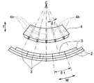
- FIG. 5 is a front view of the ultrasonic transducer viewed from the VI direction in FIG.
- the figure which shows roughly the modification with which the penetration hole which each wiring is penetrated was formed in the holding member of Drawing 4, with a piezoelectric element and an acoustic matching layer, The figure which shows schematically the state by which several wiring was penetrated to the penetration hole of FIG. 7, and was fixed to the holding member. The figure which shows schematically the state by which the bending part was each formed in the some wiring penetrated by the penetration hole of FIG. 8, and was fixed to the holding member. 9 schematically shows a state in which one end of each wiring in FIG. 9 is electrically connected to each piezoelectric element and the other end of each wiring is electrically connected to the substrate. The figure which comprises the wiring of FIG.
- each wiring, and the holding member with a reinforcement board The figure which shows schematically the board
- the front view which looked at the modification which provided the recessed part in the holding member of FIG. 17 from the XVIII direction in FIG. 18 is a partial cross-sectional view of the ultrasonic transducer along the XIX-XIX line in FIG.
- 22 is a front view of the ultrasonic transducer and adjustment member of FIG. 22 as viewed from the direction of IIXIII in FIG.
- FIG. 1 is a diagram illustrating an example of the appearance of an ultrasonic endoscope provided with the ultrasonic transducer according to the present embodiment.
- an ultrasonic endoscope 100 includes an elongated insertion portion 110 to be inserted into a subject, an operation portion 103 provided at the proximal end in the insertion direction S of the insertion portion 110, and an operation A flexible universal cord 104 extended from the portion 103 and a connector 105 provided at the extended end of the universal cord 104 constitute a main portion.
- the scissors connector 105 is provided with a light source connector 105a, an electrical connector 105b, an ultrasonic connector 105c, a suction base 105d, and an air / water supply base 105e.
- a light source device (not shown) that supplies illumination light to the light source connector 105a is detachable, and a video processor (not shown) that performs various signal processing and the like via an imaging cable (not shown) is detachable to the electrical connector 105b. It has become.
- An ultrasonic cable 106 connected to an ultrasonic observation device is detachable from the ultrasonic connector 105c, and a suction pump (not shown) is detachable from a suction base 105d via a suction tube (not shown). Furthermore, a water supply tank (not shown) is detachably attached to the air / water supply base 105e via an air supply / water supply tube (not shown).
- the insertion portion 110 includes, in order from the distal end side in the insertion direction S, a distal end portion 111, a bending portion 112 configured to be bendable in the vertical direction and the left-right direction, and a long and flexible flexible tube portion. 113 are connected to each other.
- a known convex ultrasonic transducer 1 is provided in the heel tip 111.
- the ultrasonic signal transmission cable 20 extending from the ultrasonic transducer 1 is inserted into the insertion unit 110, the operation unit 103, the universal cord 104, and the connector 105, and the extended end of the ultrasonic signal transmission cable 20 is inserted.
- the ultrasonic cable 106 Are electrically connected to the ultrasonic cable 106 by an ultrasonic connector 105c.
- an imaging unit and an illumination unit are provided in the distal end portion 111.
- a nozzle for an air / water supply conduit is provided on the outer surface of the distal end portion 111, and a front water supply conduit, a treatment instrument insertion channel (all not shown), and the like are inserted.
- the tip in the direction S is opened.
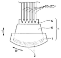
- FIG. 2 is a diagram schematically illustrating a state in which an ultrasonic signal transmission cable is electrically connected to the ultrasonic transducer of FIG. 1
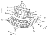
- FIG. FIG. 4 is a perspective view showing the acoustic wave transmission cable with the backing material frame and the backing material removed from the ultrasonic transducer of FIG.
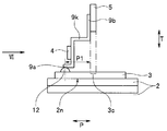
- FIG. 5 is a side view of the ultrasonic transducer of FIG. 4 viewed from the V direction in FIG. 4, and FIG. 6 is a front view of the ultrasonic transducer of FIG. 5 viewed from the VI direction in FIG. is there.
- the ultrasonic transducer 1 since the ultrasonic transducer 1 is constructed as a convex type as described above, it has two layers of acoustic matching having a center of curvature C and bending at a predetermined curvature. Layer 2 is provided.
- the number of divisions of the acoustic matching layer 2 is set to 5 to make the drawings easy to see.
- the inner surface 2n of the acoustic matching layer 2 divided into a plurality of arrays in the shape of the curvature center C side has the same center of curvature C as the two acoustic matching layers 2 and is curved.
- each piezoelectric element 3 is provided with a GND electrode (not shown) on the acoustic matching layer 2 side and a signal electrode (not shown) on the opposite side.
- a GND electrode not shown
- a signal electrode not shown
- the ultrasonic wave is radiated to the test site via the layer 2 and the lens 7 (see FIG. 2) described later, and the sound wave reflected from the test site is received, and is formed by firing, for example, ceramic. For example, it is arranged in a convex shape.
- the plurality of piezoelectric elements 3 are divided into an array at an arrangement interval W1 together with the layers on the piezoelectric element 3 side of the two acoustic matching layers 2, and the acoustic matching layer 2 is easy to see the drawing.
- the case where it is divided into five is shown as an example, but in reality, the piezoelectric element 3 and the acoustic matching layer 2 are divided into several hundreds in order to obtain a high-definition ultrasonic image. It is common.
- each end 9a of the plurality of wirings 9 is electrically connected to the signal electrodes of the plurality of piezoelectric elements 3 by solder 12 or the like.
- each end 9 a is electrically connected to the center of each piezoelectric element 3 in the bending direction W.
- connection position of each end 9 a with respect to each piezoelectric element 3 is determined from the position 3 c where a substrate 5 to be described later overlaps each piezoelectric element 3 in a planar manner.
- the matching layer 2 is shifted in the depth direction P.
- the plurality of wirings 9 are bare wires that are not covered with an insulating member to expose the conductive material in order to reduce the interval between the piezoelectric elements 3, and are, for example, wires having silver plating on the outer periphery. It is composed of
- each wiring 9 is comprised from the ultra fine wire whose outer diameter is 0.05 mm or less. Further, the number of wirings 9 is also shown as an example in accordance with the number of piezoelectric elements 3.
- each wiring 9 is made of, for example, an insulating material and is electrically connected to the substrate 5 that is positioned sufficiently apart from the plurality of piezoelectric elements 3 in the direction T to be described later. Connected.
- each wiring 9 is formed integrally with the substrate 5.
- a GND wiring land (not shown) is formed on the surface of the substrate 5 where the other end 9b is formed. Further, the separation distance of the substrate 5 from the piezoelectric element 3 in the direction T is set to a distance at which the ultrasonic waves radiated from the plurality of piezoelectric elements 3 toward the center of curvature C are not reflected by the substrate 5.
- the other ends 9b are electrically connected to ends of a plurality of signal lines 20s constituting an ultrasonic signal transmission cable 20 for transmitting and receiving at least electric power and electric signals to each piezoelectric element 3. It is connected to the.
- the number of the plurality of signal lines 20 s is also shown by taking five as an example, including the number of each wiring 9. Further, as described above, the substrate 5 is positioned in the depth direction P so as to be shifted from the connection position of each end 9 a to each piezoelectric element 3.
- the plurality of wirings 9 extend radially from the center of curvature C because the piezoelectric elements 3 are arranged in a convex shape in the direction T connecting the substrate 5 and the plurality of piezoelectric elements 3.
- bent portions 9 k that are bent in a crank shape, for example, are formed at midway positions.
- each bent portion 9k is formed between a holding member 4 (see FIGS. 4 to 6) described later and the substrate 5.
- each bent portion 9k has a crank shape, so that two places are bent at 90 °.
- the present invention is not limited to this, and two places are gently bent into a crank shape. It may be formed.
- each end 9 a side of each bent portion 9 k is made of, for example, an insulating material and has the same center of curvature C as the acoustic matching layer 2.
- the holding member 4 having a curved shape with the wiring 9 is provided integrally with the wiring 9, for example.
- the holding member 4 Since the holding member 4 has the same center of curvature C as that of the acoustic matching layer 2, the bent shapes of the bent portions 9 k are equal to each other, and the workability and the bent portions of the wires 9 are bent.
- the bent shape of 9k is easy to stabilize.
- the holding member 4 holds the plurality of wirings 9 at an equal interval W2 (W2 ⁇ W1) equal to or smaller than the arrangement interval W1 of the plurality of piezoelectric elements 3. Further, it is positioned closer to the bent portion 9k in the direction T to prevent the positional deviation of the wirings 9 and to prevent the wirings 9 from contacting each other.
- the holding member 4 holds the plurality of wirings 9 by being shifted from the arrangement interval W1 of the plurality of piezoelectric elements 3 by 1 ⁇ 2 interval, so that each of the piezoelectric elements 3 has a center in the bending direction W.
- a plurality of wirings 9 are held so that one end 9a of the wiring 9 is electrically connected.
- the plurality of piezoelectric elements 3, the connection portion of one end 9 a of each wiring 9 to each piezoelectric element 3, the holding member 4, and the bent portion 9 k are covered with a backing material frame 6.
- the backing material frame 6 is made of, for example, glass epoxy resin.
- the backing material frame 6 is formed in a frame shape by two opposing end boards and two opposing side boards so that the shape in plan view is a rectangular shape.
- the backing material frame 6 is filled with a backing material (not shown).
- the half of the backing material frame 6 on the acoustic matching layer 2 side and the outer periphery of the acoustic matching layer 2 are covered with a lens 7.
- the plurality of wirings 9 are connected between the one ends 9a and the bent portions 9k at the middle positions of the plurality of wirings 9 extending radially in the direction T. It has been shown that the holding members 4 that are held at equal intervals are provided at intervals W2 (W2 ⁇ W1) that are equal to or less than the arrangement interval W1 of the elements 3.
- each wiring 9 in the bare wire state with the conductive material exposed are deformed by an external force, the displacement of each wire 9 can be prevented by the holding member 4. Since contact can be reliably prevented, each wiring 9 can be easily connected to a plurality of piezoelectric elements 3.
- crank-shaped bent portions 9k are respectively formed between the holding member 4 and the other ends 9b at midway positions in the direction T of the wirings 9.
- connection position of the one end 9 a of each wiring 9 to each piezoelectric element 3 is shifted from the position 3 c where the substrate 5 overlaps with each piezoelectric element 3 in the depth direction P. Indicated that it is located.
- each bending portion 9k is shown to be sandwiched between the holding member 4 and the substrate 5 in the middle position in the direction T of each wiring 9.
- each bent portion of each wiring 9 is provided. Since the force applied by 9k is reduced and absorbed, it is possible to reliably prevent contact between the wirings 9 and to connect each wiring 9 to the plurality of piezoelectric elements 3 during connection work. It becomes easy.
- the acoustic transducer 1 and the ultrasonic endoscope 100 can be provided.
- FIG. 7 is a diagram schematically showing a modified example in which insertion holes through which each wiring is inserted are formed in the holding member of FIG. 4 together with the piezoelectric element and the acoustic matching layer
- FIG. 8 is a diagram of the insertion holes of FIG. It is a figure which shows roughly the state by which the some wiring was penetrated and was fixed to the holding member.
- FIG. 9 is a diagram schematically showing a state in which bent portions are respectively formed in a plurality of wires inserted through the insertion holes in FIG. 8 and fixed to the holding member
- FIG. 10 is one end of each wire in FIG. Is a diagram schematically showing a state in which is electrically connected to each piezoelectric element and the other end of each wiring is electrically connected to a substrate.
- the holding member 4 may be formed separately from the plurality of wirings 9, and a radial insertion hole 4 h may be formed in the holding member 4 along the direction T from the center of curvature C.
- Each insertion hole 4h is formed at the same angular pitch ⁇ 1 as the angular pitch ⁇ 1 of each piezoelectric element 3.
- a plurality of wires 9 formed separately from the holding member 4 are inserted into the respective insertion holes 4h, and each wire 9 is connected to the holding member 4 by an adhesive 14 or the like. Each is fixed.
- each wiring 9 is bent at the other end 9b side from the holding member 4 in a lump, thereby forming a bent portion 9k. Then, as shown in FIG. Are electrically connected to each piezoelectric element 3, and each other end 9 b is electrically connected to each wiring land 5 ra of the substrate 5 by solder 16 or the like.
- each wiring land 5ra is electrically connected to each wiring land 5rb via each wiring land 5rc, and a plurality of signal lines 20s constituting the ultrasonic signal transmission cable 20 are connected to each wiring land 5rb. The ends are electrically connected.
- each wiring 9 is formed separately from the holding member 4 and the substrate 5, it is possible to freely select the material of each wiring 9. If it uses, it becomes easy to stabilize the bending shape after formation of each bending part 9k, and subsequent workability
- FIG. 11 is a diagram schematically showing a modification in which the wiring of FIG. 10 is formed of a flat wire, and a concave portion through which the flat wire is inserted is formed in the holding member.
- each wiring 9 may be made of a flat wire, and each insertion hole shown in FIGS. 7 to 10 may be made of a recess 4m through which the flat wire is inserted. I do not care.
- a bent portion 9k is formed as in the present embodiment.
- the insertion holes 4h through which the respective wires 9 are inserted are formed in the holding member 4, but rather than the insertion holes 4h. Since the processing becomes easier when the recess 4m is formed, the manufacturing cost can be reduced.
- Each wiring 9 may be fixed to the holding member 4 with an adhesive material or the like. In this case, the manufacturing cost can be further reduced.
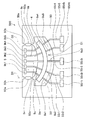
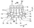
- FIG. 12 is a diagram schematically showing a modified example in which the substrate, each wiring, and the holding member of FIG. 4 are integrally formed with the discarding substrate
- FIG. FIG. 14 is a diagram showing a state in which one end of each signal line is electrically connected
- FIG. 14 shows the other end of the plurality of signal lines in FIG. 13 as a wiring land of a flexible board in the connector of the endoscope. It is a figure which shows the state electrically connected to.
- the substrate 5 and wirings 9 w, 9 u, 9 x, 9 y, 9 z formed integrally with the substrate 5, the holding member 4, the discarded substrate 50, and the discarded substrate 50 are mounted.
- a structure 500 with 55r5t is prepared.
- a hole 51 is formed in the discarded substrate 50 so as to surround the holding member 4, and a cutting hole 50 a and a cutting groove 50 b are provided between the discarded substrate 50 and the substrate 5. , 50c.
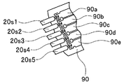
- each of the signal lines 20s1, 20s2, 20s3, 20s4, and 20s5 constituting the ultrasonic signal transmission cable 20 is connected to each of the end portions 9b1, 9b2, 9b3, 9b4, and 9b5. Electrically connected with solder or the like. At this time, each soldering portion is protected and fixed with an adhesive or the like as necessary.
- the other ends of the signal lines 20s1 to 20s5 are connected to the wiring lands 90a, 90b, 90c, 90d, and 90e of the flexible substrate 90 provided in the connector 105 of the ultrasonic endoscope 100.
- it is electrically connected with solder or the like.
- the cutting hole 50a and the cutting grooves 50b and 50c are cut along the straight lines D1 and D2, and the discarded substrate 50 and the wirings 55r1 to 55r56 are cut along the arc-shaped D3 line.
- the substrate 5, the wirings 9, and the holding member 4 are formed as shown in FIG.
- the substrate 5 and the discard substrate 50 are disposed so as to surround the wirings 9w to 9z. Therefore, the connection strength can be increased, and workability is improved because an external force is hardly applied to each of the wirings 9w to 9z.
- the check board 55 is provided with large check lands 55r1t to 55r5t, the wiring arrangement work of the signal lines 20s1 to 20s5 becomes easier than using the other ends 9b1 to 9b5 having a small arrangement interval. Since the connection positions of the signal lines 20s1 to 20s5 can be surely confirmed, the workability and the quality of the ultrasonic vibrator 1 are improved.
- FIG. 15 is an exploded view of the substrate, each wiring, and the holding member in the ultrasonic transducer of this embodiment
- FIG. 16 is a perspective view that shows the assembled state of the substrate, each wiring, and the holding member in FIG. It is.
- the configuration of the ultrasonic transducer of the second embodiment is a pair of substrate, wiring, and holding member as compared with the ultrasonic transducer of the first embodiment shown in FIGS. 1 to 6 described above. It is different in that it is composed of Therefore, the same components as those in the first embodiment are denoted by the same reference numerals, and the description thereof is omitted.
- the substrate 5 includes a first substrate 25 and a second substrate 35.
- the plurality of wirings 9 include a plurality of first wirings 29 in which the other ends 29 b are electrically connected to the first substrate 25, and each other end 39 b is electrically connected to the second substrate 35. And a plurality of second wirings 39.
- the holding member 4 is provided in the middle position of the plurality of first wires 29, and holds the first wires 29 at equal intervals W2 which are equal to or less than the arrangement interval W1 of the plurality of piezoelectric elements 3.
- a member 24 and a second holding member 34 provided in the middle of the plurality of second wirings 39 and holding the second wirings 39 at equal intervals W2 which are equal to or smaller than the arrangement interval W1 of the plurality of piezoelectric elements 3; It is composed of
- first substrate 25 and the second substrate 35 are formed in the same size and the same shape, and are connected by the connecting portion 30.
- first substrate 25 and the second substrate 35 include a connecting portion 30 having a GND terminal 27 mounted on the surface of the first substrate 25 and a GND terminal 37 mounted on the surface of the second substrate 35. Are connected to each other through wiring, and are connected at the same potential.
- the second substrate 35 is folded back 180 ° at the fold line Q via the connecting portion 30, so that the back surface of the second substrate 35 becomes the back surface of the first substrate 25. It is located overlapping.
- positioning holes 25h1 and 25h2 are formed in the first substrate 25, and positioning holes 35h1 and 35h2 are formed in the second substrate 35.
- the positioning pin 61 is inserted into 25h1 and 35h1 and the positioning pin 62 is inserted into the positioning holes 25h2 and 35h2
- the first substrate 25 and the second substrate 35 having the same shape are exactly overlapped.
- the back surfaces of the first substrate 25 and the second substrate 35 are bonded and fixed as shown in FIG.
- first wiring 29 and the second wiring 39 are spaced from the center of curvature C in a radial manner in the same manner as the wiring 9 of the first embodiment described above, similarly to the wiring 9 of the first embodiment described above.
- the first wiring 29 and the second wiring 39 have a direction in which they are separated from each other when the back surface of the first substrate 25 and the back surface of the second substrate 35 are bonded.
- the midway position in the direction T is bent outward so as to be oriented, and the zigzag state is held by the first holding member 24 and the second holding member 34 while being staggered in the bending direction W.
- the first holding member 24 and the second holding member 34 has been.
- contact between the first wiring 29 and the second wiring 39 having a small interval in the bending direction W is prevented.
- the first holding member 24 and the second holding member 34 are provided in the middle positions of the first wiring 29 and the second wiring 39 at the same position in the direction T, respectively, and have the same size and shape. Have.
- the back surface of the first holding member 24 faces the back surface of the second holding member 34 when the back surface of the first substrate 25 and the back surface of the second substrate 35 are attached.
- positioning holes 24h1 and 24h2 are formed in the first holding member 24, and positioning holes 34h1 and 34h2 are formed in the second holding member 34. As shown in FIG. When the positioning pin 63 is inserted into the positioning holes 24h1 and 34h1 and the positioning pin 64 is inserted into the positioning holes 24h2 and 34h2, the first holding member 24 and the second holding member 34 having the same shape are exactly overlapped with each other. .
- the middle position is bent outward so that the first wiring 29 and the second wiring 39 are separated from each other.
- the connecting portion 30 is arranged so that the back surfaces of the second substrate 35 and the second holding member 34 face the back surfaces of the first substrate 25 and the first holding member 24 via the connecting portion 30.
- the fold line Q is bent 180 °.
- the positioning pin 61 is inserted into the positioning holes 25h1, 35h1, the positioning pin 62 is inserted into the positioning holes 25h2, 35h2, the positioning pin 63 is inserted into the positioning holes 24h1, 34h1, and the positioning pin 64 is inserted into the positioning holes 24h2, 34h2.
- the second substrate 35 overlaps the first substrate 25, and the second holding member 34 overlaps the first holding member 24.
- the first wiring 29 and the second wiring 39 are neatly spaced by a half interval and are staggered.
- the back surface of the first substrate 25 and the back surface of the second substrate 35 are bonded and fixed, and each end 29a and each end 39a of each staggered first wiring 29 and each second wiring 39 are connected. And electrically connected to the signal electrodes of the plurality of piezoelectric elements 3.
- the wiring interval W4 in the bending direction W between the first wiring 29 and the second wiring 39 is 1/2 smaller than the interval W2 between the plurality of wirings 9 in the first embodiment described above. Therefore, it is possible to mount the wirings on the plurality of piezoelectric elements 3 at a high density with a simple configuration. Other effects are the same as those of the first embodiment described above.
- the length between the back surface of the first substrate 25 and the back surface of the second substrate 35 is longer than the length T1 of the first substrate 25 and the second substrate 35 in the direction T.
- a reinforcing plate 70 having T2 may be interposed (T1 ⁇ T2).
- the reinforcing plate 70 is formed with positioning holes 70h1 and 70h2 through which the positioning pins 61 and 62 are inserted, respectively. By inserting the positioning pins 61 and 62 into the positioning holes 70h1 and 70h2, the two boards 25 , 35, the reinforcing plate 70 is positioned.
- the substrates 25 and 35 are hardly deformed by the reinforcing plate 70.
- the reinforcing plate 70 is formed longer than the first substrate 25 and the second substrate 35 in the direction T, as shown in FIG. It is possible to reliably prevent contact between the holding member 24 and the other end 29b and the second wiring 39 between the holding member 34 and the other end 39b.
- FIG. 17 is a diagram schematically showing the substrate, each wiring, and the holding member in the ultrasonic transducer of the present embodiment.
- the configuration of the ultrasonic transducer according to the third embodiment includes a holding member and the holding member as compared with the ultrasonic transducer according to the first embodiment shown in FIGS.
- the difference is that the part of each wiring is inclined. Therefore, the same components as those in the first embodiment are denoted by the same reference numerals, and the description thereof is omitted.
- Other configurations are the same as those in the first embodiment described above.
- each piezoelectric element 3 is reflected in the depth direction P even if it hits the holding member 4, so that each piezoelectric element 3 may receive the reflected wave. Becomes lower.
- FIG. 18 is a front view of a modified example in which a concave portion is provided in the holding member in FIG. 17, viewed from the XVIII direction in FIG. 17, and FIG. 19 is a portion of the ultrasonic transducer along the XIX-XIX line in FIG. It is sectional drawing.
- a recess 4 i may be formed for each part of the holding member 4 located between the adjacent wirings 9.
- Other configurations are the same as those of the present embodiment described above.
- FIG. 20 is a view showing a modification in which a plurality of holes are formed instead of a plurality of recesses in the holding member of FIG. 18, and
- FIG. 21 is a diagram of an ultrasonic transducer along the IIXI-IIXI line in FIG. It is a fragmentary sectional view.
- a back wave U that is an ultrasonic wave radiated from a plurality of piezoelectric elements 3 is applied to the holding member 4 that is inclined at a predetermined angle with the portion 9 e with respect to the direction T.
- a plurality of holes 4j that pass therethrough may be formed.
- a hole 4j may be formed for each part of the holding member 4 located between the adjacent wirings 9.
- Other configurations are the same as those of the present embodiment described above.
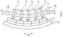
- FIG. 22 is a perspective view showing a modified example in which a fitting portion in which the adjustment member is fitted to the holding member in FIG. 4 is provided, and FIG. 23 shows the ultrasonic transducer and the adjustment member in FIG. It is the front view seen from IIXIII direction.
- each end 9a of the plurality of wirings 9 held at equal intervals in the bending direction W by the holding member 4 are electrically connected to the plurality of piezoelectric elements 3.
- each end 9a is brought into contact with each other, as shown by the dotted line in FIG. 23, each end 9a is displaced in the bending direction W with respect to the center of the bending direction W of each piezoelectric element 3.
- two arms 75 which are adjustment members that collectively adjust the positions of the plurality of wires 9, are fitted into both ends of the holding member 4 in the bending direction W.
- Adjustment holes 4h1 and 4h2 are formed as fitting portions.
- each adjustment hole 4h1 and 4h2 when each end 9 a is positioned in the bending direction W with respect to the center in the bending direction W of each piezoelectric element 3, each adjustment hole 4h1 and 4h2, the two arms 75 are respectively fitted, the two arms 75 are moved in the bending direction W, and the holding member 4 is moved in the bending direction W, whereby the holding member 4 moves in the bending direction W. Since a plurality of wirings 9 held at equal intervals can be collectively moved until each end portion 9a is positioned at the center of the bending direction W of each piezoelectric element 3 as shown by a solid line in FIG. Thus, it is possible to easily perform the positional deviation correction of each end portion 9a.
- FIGS. 22 and 23 can be applied to the first to third embodiments described above.
- FIG. 24 is a perspective view schematically showing the substrate, each wiring, and the holding member in the ultrasonic transducer together with the folding mold
- FIG. 25 is a folding mold in FIG. It is the side view which looked at the state from the IIXV direction in FIG.
- the bending part 9k may be formed, as shown in FIGS. 24 and 25, the bending part 9k may be formed collectively using the bending dies 81 and 82.
- the substrate 5 is formed with positioning holes 5h1, 5h2 penetrating in the direction P, and the holding member 4 is also formed with positioning holes 4h3, 4h4 penetrating in the direction P.
- the folding dies 81 and 82 have stepped shapes in which the respective facing surfaces 81t and 82t in the direction P are respectively fitted when the folding die 81 and the folding die 82 are combined in the direction P.
- the folding die 81 has four positioning holes 81h1, 81h2, 81h3, 81h4 penetrating in the direction P
- the folding die 82 has four positioning holes 82h1, 82h2, 82h3, 82h4 penetrating in the direction P. Is formed.
- the positioning hole 81h1 faces the positioning holes 5h1 and 82h1, and is positioned.
- the hole 81h2 faces the positioning holes 5h2, 82h2, the positioning hole 81h3 faces the positioning holes 4h3, 82h3, and the positioning hole 81h4 faces the positioning holes 4h4, 82h4.
- Positioning pins 66 are inserted into the positioning holes 81h1, 5h1, and 82h1, positioning pins 67 are inserted into the positioning holes 81h2, 5h2, and 82h2, and positioning pins 68 are inserted into the positioning holes 81h3, 4h3, and 82h3.
- the positioning pin 69 is inserted through the positioning holes 81h4, 4h4, and 82h4.
- the positioning pin 66 is inserted into the positioning holes 81h1, 5h1, and 82h1
- the positioning pin 67 is inserted into the positioning holes 81h2, 5h2, and 82h2
- the positioning pins are inserted into the positioning holes 81h3, 4h3, and 82h3.
- 68, and positioning is performed by inserting a positioning pin 69 into the positioning holes 81h4, 4h4, and 82h4.
- the opposing surface 81t of the bending die 81 and the opposing surface 82t of the bending die 82 are fitted to each other, whereby the staircase shape of each of the opposing surfaces 81t and 82t is provided for the plurality of wirings 9.
- a crank-shaped bent portion 9k is formed in a lump.
- the bent portions 9k can be formed in a batch in a short time.
- each bending portion 9k by using the bending dies 81 and 82 to form each bending portion 9k, the bending angle of the bending portion 9k and the accuracy of the formation position of each bending portion 9k with respect to each wiring 9 are improved. It is possible to suppress vibration variations of the piezoelectric elements 3.
Landscapes
- Health & Medical Sciences (AREA)
- Life Sciences & Earth Sciences (AREA)
- Engineering & Computer Science (AREA)
- Mechanical Engineering (AREA)
- Medical Informatics (AREA)
- Animal Behavior & Ethology (AREA)
- Radiology & Medical Imaging (AREA)
- Nuclear Medicine, Radiotherapy & Molecular Imaging (AREA)
- Biomedical Technology (AREA)
- Heart & Thoracic Surgery (AREA)
- Physics & Mathematics (AREA)
- Molecular Biology (AREA)
- Surgery (AREA)
- Pathology (AREA)
- General Health & Medical Sciences (AREA)
- Public Health (AREA)
- Veterinary Medicine (AREA)
- Biophysics (AREA)
- Ultra Sonic Daignosis Equipment (AREA)
- Transducers For Ultrasonic Waves (AREA)
- Investigating Or Analyzing Materials By The Use Of Ultrasonic Waves (AREA)
Abstract
Description
図1は、本実施の形態の超音波振動子が設けられた超音波内視鏡の外観の一例を示す図である。
図15は、本実施の形態の超音波振動子における基板、各配線、保持部材の分解図、図16は、図15の基板、各配線、保持部材を組み立てた状態を補強板とともに示す斜視図である。
図17は、本実施の形態の超音波振動子における基板、各配線、保持部材を概略的に示す図である。
本出願は、2014年11月21日に日本国に出願された特願2014-236901号を優先権主張の基礎として出願するものであり、上記の内容は、本願明細書、請求の範囲、図面に引用されたものである。
Claims (11)
- 所定の曲率を有して湾曲する音響整合層と、
前記音響整合層の曲率中心側の内面に湾曲して配置された複数の圧電素子と、
前記複数の圧電素子にそれぞれ一端が電気的に接続された複数の配線と、
前記複数の配線の他端がそれぞれ電気的に接続された基板と、
前記複数の圧電素子と前記基板との間における前記複数の配線の中途位置に設けられた、前記複数の配線を、前記複数の圧電素子の配列間隔以下の間隔に保持する保持部材と、
を具備することを特徴とする超音波振動子。 - 前記保持部材は、前記複数の配線を、前記複数の圧電素子の配列間隔から1/2間隔ずれて保持するとともに、前記音響整合層と同じ曲率中心を有して湾曲する形状を有していることを特徴とする請求項1に記載の超音波振動子。
- 前記保持部材は、前記複数の圧電素子における湾曲方向の各中心に対して、前記複数の配線の各前記一端が電気的に接続されるよう、前記複数の配線を保持していることを特徴とする請求項2に記載の超音波振動子。
- 前記複数の圧電素子に対する前記複数の配線の各前記一端の接続位置は、前記複数の圧電素子に対して前記基板が平面的に重なる位置からずれていることを特徴とする請求項1~3のいずれか1項に記載の超音波振動子。
- 前記複数の配線の中途位置において、前記他端と前記保持部材との間に、折り曲げ部が形成されていることを特徴とする請求項1~4のいずれか1項に記載の超音波振動子。
- 前記保持部材に、前記複数の配線が挿通される凹部または挿通孔が形成されていることを特徴とする請求項1~5のいずれか1項に記載の超音波振動子。
- 前記保持部材及び該保持部材が設けられた前記複数の配線の部位は、前記基板と前記複数の圧電素子とを結ぶ方向に対して所定の角度傾いていることを特徴とする請求項1~6のいずれか1項に記載の超音波振動子。
- 前記保持部材に、前記複数の圧電素子から放射された超音波が通過する孔または凹部が形成されていることを特徴とする請求項7に記載の超音波振動子。
- 前記保持部材に、前記複数の配線の位置を一括して調整する調整部材の嵌合部が形成されていることを特徴とする請求項1~8のいずれか1項に記載の超音波振動子。
- 前記基板は、第1の基板と、該第1の基板の背面に対し同電位となるよう連設された第2の基板とを有するとともに、前記複数の配線は、前記第1の基板に前記他端が電気的に接続された複数の第1の配線と、前記第2の基板に前記他端が電気的に接続された複数の第2の配線とを有し、さらに、前記保持部材は、前記複数の第1の配線を保持する第1の保持部材と、前記複数の第2の配線を保持する第2の保持部材とを有し、
前記第1の保持部材及び前記第2の保持部材は、前記複数の第1の配線と前記複数の第2の配線とが1/2間隔ずれるとともに互いに離間する方向を指向するよう、前記複数の第1の配線と前記複数の第2の配線とを千鳥状に保持していることを特徴とする請求項1~9のいずれか1項に記載の超音波振動子。 - 請求項1~10のいずれか1項に記載の前記超音波振動子を具備する超音波内視鏡。
Priority Applications (4)
| Application Number | Priority Date | Filing Date | Title |
|---|---|---|---|
| EP15861529.4A EP3165169B1 (en) | 2014-11-21 | 2015-10-15 | Ultrasonic vibrator and ultrasonic endoscope |
| CN201580031780.9A CN106456133B (zh) | 2014-11-21 | 2015-10-15 | 超声波振子、超声波内窥镜 |
| JP2016528039A JP6010259B1 (ja) | 2014-11-21 | 2015-10-15 | 超音波振動子、超音波内視鏡 |
| US15/422,527 US9919343B2 (en) | 2014-11-21 | 2017-02-02 | Ultrasound transducer and ultrasound endoscope |
Applications Claiming Priority (2)
| Application Number | Priority Date | Filing Date | Title |
|---|---|---|---|
| JP2014-236901 | 2014-11-21 | ||
| JP2014236901 | 2014-11-21 |
Related Child Applications (1)
| Application Number | Title | Priority Date | Filing Date |
|---|---|---|---|
| US15/422,527 Continuation US9919343B2 (en) | 2014-11-21 | 2017-02-02 | Ultrasound transducer and ultrasound endoscope |
Publications (1)
| Publication Number | Publication Date |
|---|---|
| WO2016080119A1 true WO2016080119A1 (ja) | 2016-05-26 |
Family
ID=56013677
Family Applications (1)
| Application Number | Title | Priority Date | Filing Date |
|---|---|---|---|
| PCT/JP2015/079185 Ceased WO2016080119A1 (ja) | 2014-11-21 | 2015-10-15 | 超音波振動子、超音波内視鏡 |
Country Status (5)
| Country | Link |
|---|---|
| US (1) | US9919343B2 (ja) |
| EP (1) | EP3165169B1 (ja) |
| JP (1) | JP6010259B1 (ja) |
| CN (1) | CN106456133B (ja) |
| WO (1) | WO2016080119A1 (ja) |
Cited By (1)
| Publication number | Priority date | Publication date | Assignee | Title |
|---|---|---|---|---|
| US11872081B2 (en) | 2019-03-29 | 2024-01-16 | Olympus Corporation | Ultrasound transducer, ultrasound endoscope, and manufacturing method of ultrasound transducer |
Families Citing this family (2)
| Publication number | Priority date | Publication date | Assignee | Title |
|---|---|---|---|---|
| CN113631099B (zh) * | 2019-03-29 | 2023-09-19 | 泰尔茂株式会社 | 图像诊断用导管 |
| CN115235521A (zh) * | 2021-04-23 | 2022-10-25 | 苏州佳世达电通有限公司 | 水下超音波装置 |
Citations (3)
| Publication number | Priority date | Publication date | Assignee | Title |
|---|---|---|---|---|
| JPH01146499A (ja) * | 1987-12-02 | 1989-06-08 | Nippon Dempa Kogyo Co Ltd | 超音波探触子 |
| JPH0641708U (ja) * | 1992-03-30 | 1994-06-03 | テルモ株式会社 | 超音波探触子 |
| JP2001198126A (ja) * | 2000-01-24 | 2001-07-24 | Toshiba Corp | 超音波プローブと、その製造方法 |
Family Cites Families (21)
| Publication number | Priority date | Publication date | Assignee | Title |
|---|---|---|---|---|
| JPS54151397U (ja) * | 1978-04-14 | 1979-10-20 | ||
| JPS56161799A (en) * | 1980-05-15 | 1981-12-12 | Matsushita Electric Ind Co Ltd | Ultrasonic wave probe |
| JPS5711648A (en) * | 1980-06-27 | 1982-01-21 | Matsushita Electric Industrial Co Ltd | Ultrasonic probe |
| JPS6278909U (ja) * | 1985-11-01 | 1987-05-20 | ||
| JPH0834651B2 (ja) * | 1988-04-27 | 1996-03-29 | 富士通株式会社 | 超音波探触子の製造方法 |
| JPH0354997A (ja) * | 1989-07-24 | 1991-03-08 | Nippon Dempa Kogyo Co Ltd | 超音波探触子 |
| JPH0542146A (ja) * | 1991-08-14 | 1993-02-23 | Olympus Optical Co Ltd | 超音波プローブ |
| JP3331509B2 (ja) * | 1994-08-30 | 2002-10-07 | 日本電波工業株式会社 | コンベックス型超音波探触子とその製造方法 |
| JPH0889505A (ja) * | 1994-09-27 | 1996-04-09 | Toshiba Corp | 超音波プローブの製造方法 |
| JP3487981B2 (ja) | 1994-10-20 | 2004-01-19 | オリンパス株式会社 | 超音波プローブ |
| JPH11169369A (ja) * | 1997-12-10 | 1999-06-29 | Toshiba Corp | 3次元超音波プローブ |
| US6558323B2 (en) * | 2000-11-29 | 2003-05-06 | Olympus Optical Co., Ltd. | Ultrasound transducer array |
| JP3878817B2 (ja) * | 2001-04-19 | 2007-02-07 | 日本電波工業株式会社 | 超音波探触子 |
| JP4405772B2 (ja) * | 2003-10-03 | 2010-01-27 | ジーイー・メディカル・システムズ・グローバル・テクノロジー・カンパニー・エルエルシー | 超音波プローブおよびその製造方法 |
| US7569975B2 (en) * | 2006-11-07 | 2009-08-04 | Olympus Ndt | Cable direct interconnection (CDI) method for phased array transducers |
| JP5146815B2 (ja) * | 2008-03-01 | 2013-02-20 | 国立大学法人東北大学 | 超音波プローブ、内視鏡及び超音波プローブの製造方法 |
| JP5611645B2 (ja) * | 2010-04-13 | 2014-10-22 | 株式会社東芝 | 超音波トランスデューサおよび超音波プローブ |
| WO2012075153A2 (en) * | 2010-12-03 | 2012-06-07 | Research Triangle Institute | Ultrasound device, and associated cable assembly |
| CN103648404B (zh) * | 2012-07-04 | 2015-06-17 | 奥林巴斯医疗株式会社 | 超声波内窥镜 |
| EP2740411A4 (en) * | 2012-08-27 | 2015-04-15 | Olympus Medical Systems Corp | ULTRASOUND ENDOSCOPE |
| EP3305203A4 (en) * | 2015-05-25 | 2019-01-09 | Olympus Corporation | ULTRASOUND PROBE |
-
2015
- 2015-10-15 JP JP2016528039A patent/JP6010259B1/ja active Active
- 2015-10-15 EP EP15861529.4A patent/EP3165169B1/en active Active
- 2015-10-15 CN CN201580031780.9A patent/CN106456133B/zh active Active
- 2015-10-15 WO PCT/JP2015/079185 patent/WO2016080119A1/ja not_active Ceased
-
2017
- 2017-02-02 US US15/422,527 patent/US9919343B2/en active Active
Patent Citations (3)
| Publication number | Priority date | Publication date | Assignee | Title |
|---|---|---|---|---|
| JPH01146499A (ja) * | 1987-12-02 | 1989-06-08 | Nippon Dempa Kogyo Co Ltd | 超音波探触子 |
| JPH0641708U (ja) * | 1992-03-30 | 1994-06-03 | テルモ株式会社 | 超音波探触子 |
| JP2001198126A (ja) * | 2000-01-24 | 2001-07-24 | Toshiba Corp | 超音波プローブと、その製造方法 |
Non-Patent Citations (1)
| Title |
|---|
| See also references of EP3165169A4 * |
Cited By (1)
| Publication number | Priority date | Publication date | Assignee | Title |
|---|---|---|---|---|
| US11872081B2 (en) | 2019-03-29 | 2024-01-16 | Olympus Corporation | Ultrasound transducer, ultrasound endoscope, and manufacturing method of ultrasound transducer |
Also Published As
| Publication number | Publication date |
|---|---|
| US9919343B2 (en) | 2018-03-20 |
| US20170144194A1 (en) | 2017-05-25 |
| CN106456133B (zh) | 2019-09-17 |
| JP6010259B1 (ja) | 2016-10-19 |
| EP3165169A4 (en) | 2018-03-28 |
| EP3165169B1 (en) | 2023-02-22 |
| JPWO2016080119A1 (ja) | 2017-04-27 |
| CN106456133A (zh) | 2017-02-22 |
| EP3165169A1 (en) | 2017-05-10 |
Similar Documents
| Publication | Publication Date | Title |
|---|---|---|
| CN103300883B (zh) | 超声波探头及超声波探头的制造方法 | |
| CN100435741C (zh) | 小型化超声换能器 | |
| JP5973761B2 (ja) | ケーブル接続構造 | |
| US8517949B2 (en) | Ultrasound transducer unit and ultrasound endoscope | |
| EP2266712B1 (en) | Transducer for ultrasonic diagnosis device and method for manufacturing the same | |
| JP2014502201A (ja) | 超音波デバイスの形成方法、および関連する装置 | |
| JP5705386B1 (ja) | 超音波振動子及び超音波振動子の製造方法 | |
| CN105640588B (zh) | 深脑刺激与神经调控的大规模面阵超声探头及其制备方法 | |
| JP2017148512A (ja) | 高周波超音波プローブ | |
| US20190110773A1 (en) | Ultrasound endoscope and methods of manufacture thereof | |
| JP6010259B1 (ja) | 超音波振動子、超音波内視鏡 | |
| CN110381847A (zh) | 超声波振子、超声波内窥镜以及超声波振子的制造方法 | |
| JP3450430B2 (ja) | 超音波トランスジューサ | |
| US20150279764A1 (en) | Semiconductor device connection structure, ultrasonic module, and ultrasonic endoscope system having ultrasonic module | |
| JP2013144063A (ja) | 超音波ユニット、超音波内視鏡、および超音波ユニットの製造方法 | |
| US20090204006A1 (en) | Ultrasonic transducer, ultrasonic transducer array and ultrasonic endoscope system | |
| JP6132963B2 (ja) | ケーブル接続構造、超音波探触子および超音波内視鏡システム | |
| JP4746302B2 (ja) | 超音波探触子 | |
| CN109259795A (zh) | 接合中间件和集成电路芯片的方法及用该法的超声波探头 | |
| JP3934202B2 (ja) | 超音波探触子 | |
| JP3851743B2 (ja) | 電子走査型超音波探触子 | |
| CN116602063A (zh) | 基板的连接构造及超声波诊断装置 | |
| US20190133555A1 (en) | Ultrasonic transducer module and ultrasonic endoscope | |
| JP2013098581A (ja) | 超音波ユニット、超音波内視鏡、および超音波ユニットの製造方法 | |
| JP2018064744A (ja) | 超音波振動子、超音波内視鏡、及び超音波振動子の製造方法 |
Legal Events
| Date | Code | Title | Description |
|---|---|---|---|
| ENP | Entry into the national phase |
Ref document number: 2016528039 Country of ref document: JP Kind code of ref document: A |
|
| 121 | Ep: the epo has been informed by wipo that ep was designated in this application |
Ref document number: 15861529 Country of ref document: EP Kind code of ref document: A1 |
|
| REEP | Request for entry into the european phase |
Ref document number: 2015861529 Country of ref document: EP |
|
| WWE | Wipo information: entry into national phase |
Ref document number: 2015861529 Country of ref document: EP |
|
| NENP | Non-entry into the national phase |
Ref country code: DE |