WO2016080284A1 - 誘導電動機 - Google Patents
誘導電動機 Download PDFInfo
- Publication number
- WO2016080284A1 WO2016080284A1 PCT/JP2015/081902 JP2015081902W WO2016080284A1 WO 2016080284 A1 WO2016080284 A1 WO 2016080284A1 JP 2015081902 W JP2015081902 W JP 2015081902W WO 2016080284 A1 WO2016080284 A1 WO 2016080284A1
- Authority
- WO
- WIPO (PCT)
- Prior art keywords
- rotor
- stator
- teeth
- core
- induction motor
- Prior art date
- Legal status (The legal status is an assumption and is not a legal conclusion. Google has not performed a legal analysis and makes no representation as to the accuracy of the status listed.)
- Ceased
Links
Images


Classifications
-
- H—ELECTRICITY
- H02—GENERATION; CONVERSION OR DISTRIBUTION OF ELECTRIC POWER
- H02K—DYNAMO-ELECTRIC MACHINES
- H02K17/00—Asynchronous induction motors; Asynchronous induction generators
- H02K17/02—Asynchronous induction motors
- H02K17/16—Asynchronous induction motors having rotors with internally short-circuited windings, e.g. cage rotors
-
- H—ELECTRICITY
- H02—GENERATION; CONVERSION OR DISTRIBUTION OF ELECTRIC POWER
- H02K—DYNAMO-ELECTRIC MACHINES
- H02K1/00—Details of the magnetic circuit
- H02K1/06—Details of the magnetic circuit characterised by the shape, form or construction
- H02K1/12—Stationary parts of the magnetic circuit
- H02K1/16—Stator cores with slots for windings
-
- H—ELECTRICITY
- H02—GENERATION; CONVERSION OR DISTRIBUTION OF ELECTRIC POWER
- H02K—DYNAMO-ELECTRIC MACHINES
- H02K1/00—Details of the magnetic circuit
- H02K1/06—Details of the magnetic circuit characterised by the shape, form or construction
- H02K1/22—Rotating parts of the magnetic circuit
- H02K1/26—Rotor cores with slots for windings
-
- H—ELECTRICITY
- H02—GENERATION; CONVERSION OR DISTRIBUTION OF ELECTRIC POWER
- H02K—DYNAMO-ELECTRIC MACHINES
- H02K17/00—Asynchronous induction motors; Asynchronous induction generators
- H02K17/02—Asynchronous induction motors
- H02K17/16—Asynchronous induction motors having rotors with internally short-circuited windings, e.g. cage rotors
- H02K17/20—Asynchronous induction motors having rotors with internally short-circuited windings, e.g. cage rotors having deep-bar rotors
-
- H—ELECTRICITY
- H02—GENERATION; CONVERSION OR DISTRIBUTION OF ELECTRIC POWER
- H02K—DYNAMO-ELECTRIC MACHINES
- H02K1/00—Details of the magnetic circuit
- H02K1/06—Details of the magnetic circuit characterised by the shape, form or construction
- H02K1/22—Rotating parts of the magnetic circuit
- H02K1/24—Rotor cores with salient poles ; Variable reluctance rotors
-
- H—ELECTRICITY
- H02—GENERATION; CONVERSION OR DISTRIBUTION OF ELECTRIC POWER
- H02K—DYNAMO-ELECTRIC MACHINES
- H02K2201/00—Specific aspects not provided for in the other groups of this subclass relating to the magnetic circuits
- H02K2201/03—Machines characterised by aspects of the air-gap between rotor and stator
-
- H—ELECTRICITY
- H02—GENERATION; CONVERSION OR DISTRIBUTION OF ELECTRIC POWER
- H02K—DYNAMO-ELECTRIC MACHINES
- H02K2213/00—Specific aspects, not otherwise provided for and not covered by codes H02K2201/00 - H02K2211/00
- H02K2213/03—Machines characterised by numerical values, ranges, mathematical expressions or similar information
Definitions
- Embodiments of the present invention relate to an induction motor.
- This squirrel-cage induction motor is provided on a substantially cylindrical stator core having a plurality of stator slots, a stator in which a stator coil is disposed, a radially inner side of the stator, and And a rotor provided rotatably.
- the rotor has a rotating shaft and a rotor iron core that is externally fixed to the rotating shaft.
- a plurality of rotor teeth extending in the radial direction are radially arranged in the rotor core, and rotor slots are formed between the rotor teeth adjacent in the circumferential direction.
- a rotor bar (conductor bar) is disposed in the rotor slot.
- end rings (end-to-end rings) formed in an annular shape so as to surround the periphery of the rotation shaft are provided.
- These rotor bars and end rings are configured as secondary conductors. The rotor rotates by the interaction between the magnetic field generated on the stator side and the induced current generated in the secondary conductor by this magnetic field.
- induction motor efficiency regulations top runner regulations
- induction motors used for main motors of railway vehicles are also being improved in efficiency from the viewpoints of energy saving, noise reduction, and further miniaturization.
- spatial harmonic components also increase, resulting in higher harmonic secondary copper loss (copper loss on the rotor side), which may deteriorate motor characteristics.
- the problem to be solved by the present invention is to provide an induction motor that can improve motor characteristics such as loss reduction, and can be downsized and highly efficient.
- the induction motor of the embodiment has a stator and a rotor.
- a stator coil is arranged on a stator core having a plurality of stator slots.
- the rotor has a rotor core provided so as to be rotatable with respect to the stator.
- the rotor core has a plurality of rotor teeth and a rotor slot formed between the plurality of rotor teeth and in which a rotor conduction portion is disposed.
- the rotor teeth have a teeth main body portion and a collar portion.
- the teeth main body extends along the radial direction of the rotor core.
- the collar extends from the tip of the teeth body along the direction of rotation of the rotor core.
- the hollow surface is formed in at least one part of the outer peripheral surface of the radial direction outer side in a collar part.
- the recessed surface is further away from the stator core than the end surface on the radially outer side of the teeth main body as it goes toward the front end in the rotational direction.
- the collar part is tapered as it goes to the front end in the rotation direction.
- FIG. 2 is a sectional view taken along line AA in FIG. 1.
- the B section enlarged view of FIG. The graph which shows the change of the relative value of the rotor copper loss of 1st Embodiment.
- wire of FIG. The schematic block diagram which shows the induction motor of 3rd Embodiment.
- FIG. 9 is a cross-sectional view taken along line HH in FIG. 8.
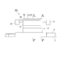
- FIG. 1 is a schematic configuration diagram of the induction motor 1.
- FIG. 2 is a cross-sectional view taken along line AA in FIG.
- the induction motor 1 includes a substantially cylindrical stator 2, and a rotor 3 that is disposed radially inward of the stator 2 and is rotatably provided to the stator 2.
- the scale of each member is appropriately changed for easy explanation.
- the axial direction of the rotor 2 is simply referred to as an axial direction
- the rotational direction of the rotor 2 is referred to as a circumferential direction
- the radial direction of the rotor 2 is simply referred to as a radial direction.
- the stator 2 has a substantially cylindrical stator core 4.
- the stator core 4 is formed by, for example, laminating a plurality of electromagnetic steel plates along the axial direction. Both ends of the stator core 4 in the axial direction are held by a stator core presser 4a.
- the electromagnetic steel sheet is a thin steel sheet manufactured by adding silicon to iron.
- stator teeth 5 projecting toward the radial center of the stator core 4 are formed on the inner peripheral surface side of the stator core 4. These stator teeth 5 are arranged at equal intervals along the circumferential direction. In addition, stator slots 6 are formed between the stator teeth 5 adjacent in the circumferential direction. A stator coil 7 is disposed in each stator slot 6.
- the rotor 3 has a rotating shaft 8 that is disposed at the radial center of the stator core 4 and is rotatably supported by a bearing (not shown).
- a substantially cylindrical rotor core 9 is fitted and fixed at a position corresponding to the stator core 4 of the rotary shaft 8.
- the rotor core 9 is formed by, for example, laminating a plurality of electromagnetic steel plates along the axial direction.
- a through hole 9 a into which the rotary shaft 8 can be inserted or press-fitted is formed on the inner side in the radial direction of the rotor core 9. The rotary shaft 8 is inserted into the through hole 9a.
- a plurality of rotor teeth 10 protruding outward in the radial direction are formed on the outer peripheral surface side of the rotor core 9. These rotor teeth 10 are radially arranged at equal intervals along the circumferential direction.
- the rotor teeth 10 are formed in a substantially T-shaped cross section.
- the rotor tooth 10 includes a tooth main body 11 extending along the radial direction and a flange 12 extending along the circumferential direction from the tip of the tooth main body 11.
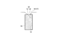
- FIG. 3 is an enlarged view of a portion B in FIG.
- the flange portion 12 is provided with a recess portion 16 on the outer circumferential surface on the radially outer side.
- the recess 16 is provided over the entire axial direction of the rotor tooth 10.
- the flange portion 12 gradually moves toward the distal end in the circumferential direction with the base point P being a point where the outer peripheral surface of the flange portion 12 and the extension line L of the side surface of the tooth main body portion 11 intersect. It is formed to be tapered.
- the hollow portion 16 is formed on the outer peripheral surface of the flange portion 12, and gradually from the base point P toward the distal end in the circumferential direction of the flange portion 12, more gradually than the end surface on the radially outer side of the teeth body portion 11.
- 9 is an inclined surface 17 formed so as to be separated from 9.
- action of the hollow part 16 is mentioned later.
- a rotor slot 13 is formed between the rotor teeth 10 thus formed.
- a rotor bar 14 having a substantially rectangular cross section is disposed at a portion of the rotor slot 13 surrounded by the teeth main body 11 and the flange 12.
- the rotor bar 14 is made of a conductor such as copper or aluminum and is made of a nonmagnetic material.
- annular end rings 15 are provided at both axial ends of the rotor bar 14.
- the end ring 15 is also made of the same material as the rotor bar 14.
- the stator coil 7 In order to operate the induction motor 1, the stator coil 7 is energized. When the stator coil 7 is energized, a magnetic flux is formed in the stator core 4. This magnetic flux passes through the rotor teeth via the stator teeth 5. Then, an induced current is generated in the rotor bar 14 and the end ring 15, and the rotor 3 is rotated by the interaction between the induced current and the magnetic flux formed in the stator core 4.
- the magnetic flux passes through the rotor teeth 10, the magnetic flux does not pass so much through the rotor slots 13 formed between the rotor teeth 10 adjacent in the circumferential direction. That is, when viewed from the outer peripheral surface of the rotor core 9, the change in magnetic flux density is large between the location where the rotor teeth 10 are formed and the location where the rotor slots 13 are formed.
- the magnetic flux fluctuates according to the rotation angle of the rotor 3, and this becomes a spatial harmonic, resulting in harmonic secondary copper loss (copper loss of the rotor bar 14). It gets bigger.
- the rotor bar 14 is arranged on the outer peripheral surface side of the rotor core 9 in order to reduce the leakage inductance, but in this case, the influence of spatial harmonics on the radially outer side of the rotor bar 14 becomes large. This is because the harmonic secondary copper loss increases.
- a recessed portion 16 is formed in the flange portion 12 of the rotor tooth 10. For this reason, the gap between the flange 12 and the stator 2 gradually increases toward the distal end of the flange 12 in the circumferential direction. In other words, the flange portion 12 is formed so as to taper toward the tip, so that the magnetic flux hardly passes through the flange portion 12.
- the change in the magnetic flux density between the rotor teeth 10 and the rotor slots 13 is not a sudden change but a smooth change. Further, since the magnetic flux does not easily pass through the circumferential end of the flange portion 12, the influence of the spatial harmonics on the radially outer side of the rotor bar 14 facing the radial direction on the distal end side is reduced. Further, by providing the recess portion 16 in the flange portion 12, the leakage magnetic flux on the tip side of the flange portion 12 is reduced as compared with the case where the recess portion 16 is not provided, and the leakage inductance does not increase or decrease much.
- FIG. 4 is a graph showing the change in the relative value of the rotor copper loss when the vertical axis is the relative value (%) of the rotor copper loss and the horizontal axis is the relative value (%) of the depth of the recess 16. It is.
- the relative value of the rotor copper loss is 100% when the recess 16 is not provided.
- the relative value of the depth of the hollow part 16 is set to 0% when the hollow part 16 is not provided. That is, when the relative value of the depth of the recessed portion 16 is 100%, the recessed portion 16 is formed by the thickness of the flange portion 12 in the radial direction.
- the recess bar 16 is provided on the distal end side in the circumferential direction of the flange portion 12, so that the rotor bar 14 is not disposed on the radially inner side of the rotor core 9.
- the secondary copper loss due to the influence of the spatial harmonics on the rotor bar 14 can be reduced. For this reason, the small and highly efficient induction motor 1 can be provided.
- FIG. 5 is a schematic configuration diagram of the induction motor 201 in the second embodiment, and corresponds to a cross-sectional view taken along the line CC of FIG. 6 is a cross-sectional view taken along the line DD of FIG.
- the same reference numerals are given to the same aspects as those of the first embodiment, and the description thereof is omitted (the same applies to the following embodiments).
- the recess 16 inclined surface 17 formed in the flange 12 of the rotor tooth 10 is formed in the entire axial direction of the flange 12.
- the rotor teeth 10 are formed at positions avoiding both ends in the axial direction. This is different from the first embodiment described above.
- the cross-sectional shape (a cross-sectional shape along the line EE in FIG. 5) at a position avoiding both axial ends of the rotor teeth 10 is the same as that in FIG. 3 in the first embodiment described above.
- harmonic secondary copper loss can be reduced, while the recess portion 16 is provided.
- the rigidity of the iron core 9 is weakened, and the holding strength of the rotor bar 14 in the rotor iron core 9 is weakened.
- the axially opposite ends of the flange portion 12 are formed. Stiffness can be increased.
- the harmonic secondary copper loss can be reduced while ensuring the rigidity of the rotor core 9.
- variety of the axial direction of the location which does not form the hollow part 16 can be set arbitrarily.
- the following method is conceivable as a method for setting the axial width of the portion where the recess 16 is not formed. That is, the wider the formation range of the hollow portion 16, the higher the harmonic secondary copper loss can be suppressed, while the wider the range where the hollow portion 16 is not formed, the higher the rigidity of the rotor core 9. be able to. For this reason, the axial width of the portion where the recess 16 is not formed is set from the balance between the relative value (%) of the harmonic secondary copper loss to be suppressed and the rigidity of the rotor core 9 to be secured.
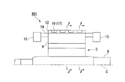
- FIG. 7 is a schematic configuration diagram of the induction motor 301 in the third embodiment, and corresponds to a cross-sectional view taken along the line CC in FIG.
- FIG. 8 is a cross-sectional view taken along line HH in FIG.
- the inclination gradient of the recess 16 (inclined surface 17) formed in the flange 12 of the rotor tooth 10 gradually increases toward the axial center. It is set to be steep. This is different from the first embodiment described above.
- the cross-sectional shape (the cross-sectional shape along the line FF in FIG. 7) at both ends in the axial direction of the rotor tooth 10 is the same as that in FIG. 6 in the second embodiment described above.
- the cross-sectional shape (the cross-sectional shape along the line GG in FIG. 7) between the axial ends of the rotor teeth 10 and the central portion in the axial direction is the first embodiment described above. It is the same as that of FIG. 3 in the form.
- the harmonic secondary copper loss increases toward the axial center of the rotor core 9. For this reason, a harmonic secondary copper loss can be efficiently reduced by changing the inclination gradient of the hollow part 16 (inclined surface 17) so as to correspond to the magnitude of the harmonic secondary copper loss. Moreover, since it is comprised so that it may not cut out the collar part 12 as much as possible, the rigidity of the rotor core 9 can be ensured and the fall of the retention strength of the rotor bar 14 by the rotor core 9 can be suppressed.
- FIG. 9 is a schematic configuration diagram of the induction motor 401 in the fourth embodiment, and corresponds to a cross-sectional view taken along the line CC of FIG. 2 described above.
- the recessed part 16 formed in the collar part 12 of the rotor teeth 10 is arrange
- the cross-sectional shape (the cross-sectional shape along the line II in FIG. 9) of the portion where the recess portion 16 is formed in the flange portion 12 of the rotor tooth 10 is the same as that in FIG. 6 in the second embodiment described above. It is. Further, the cross-sectional shape (the cross-sectional shape along the line JJ in FIG. 9) of the portion where the recess portion 16 is not formed in the flange portion 12 of the rotor tooth 10 is the same as that in FIG. 3 in the first embodiment described above. It is.
- the width in the axial direction of the hollow portion 16 formed in the collar portion 12 is set to a predetermined width.
- a plurality (for example, four in this embodiment) of the recessed portions 16 are arranged at equal intervals along the axial direction.
- the location in which the hollow part 16 is formed and the location in which the hollow part 16 is not formed are arrange
- the harmonic secondary copper loss can be reduced, while the equivalent air gap magnetic resistance is increased, so that the rotational torque of the induction motor 401 is reduced.
- the induction motor is provided while reducing the harmonic secondary copper loss by alternately arranging the locations where the recesses 16 are formed and the locations where the recesses 16 are not formed in the flange portion 12. A rotational torque of 401 can be ensured.
- the present invention is not limited to this, and the axial widths of the respective recessed portions 16 may not be set to be the same. Moreover, it is not necessary to arrange
- FIG. 10 is an enlarged plan view of the flange 12 in the fifth embodiment. As shown in the figure, the difference between the first embodiment and the fifth embodiment described above is that the shape of the recess 16 in the first embodiment and the shape of the recess 516 in the fifth embodiment. Is in a different point.
- the recessed portion 516 in the fifth embodiment is formed on the outer peripheral surface of the flange portion 12, and gradually becomes an end surface on the radially outer side of the teeth main body portion 11 toward the distal end in the circumferential direction of the flange portion 12. It is a surface which is curved and formed in a concave shape so as to be further away from the stator core 9. Even if formed in this way, the same effects as those of the first embodiment described above can be obtained. In addition, you may curve and form the hollow part 516 to a protruding item
- the depressions 16 and 516 have a base point P () at a point where the outer peripheral surface of the flange portion 12 and the extension line L of the side surface of the teeth body portion 11 intersect.
- P the case where the taper is formed so as to be gradually tapered toward the tip in the circumferential direction has been described.
- the present invention is not limited to this. That is, as shown in FIGS. 2 and 3, a straight line CL1 passing through the center of the stator slot 6 in the width direction and the axis C of the rotation shaft 8 (rotation axis of the rotor 3; see FIG.
- the induction motors 1, 201, 301, 401 can be used for various purposes.
- the rotor bar 14 is moved closer to the radially inner side of the rotor core 9. Therefore, it is possible to reduce harmonic secondary copper loss due to the influence of spatial harmonics on the rotor bar 14. For this reason, a small and highly efficient induction motor can be provided.
Landscapes
- Engineering & Computer Science (AREA)
- Power Engineering (AREA)
- Iron Core Of Rotating Electric Machines (AREA)
- Induction Machinery (AREA)
Abstract
Description
そして、回転子は、固定子側に発生する磁界と、この磁界により二次導体に生じる誘導電流との相互作用によって回転する。
ここで、誘導電動機の小型化、高トルク化を図る場合、固定子鉄心と回転子鉄心との間に形成される空隙部の磁束密度を高める必要がある。しかしながら、空間高調波成分も多くなり、それによる高調波二次銅損(回転子側の銅損)も大きくなってしまい、モータ特性が悪化してしまう可能性があった。
まず、図1~図4に基づいて、第1の実施形態について説明する。
図1は、誘導電動機1の概略構成図である。図2は、図1のA-A線に沿う断面図である。
図1、図2に示すように誘導電動機1は、略円筒状の固定子2と、固定子2よりも径方向内側に配置され、固定子2に対して回転自在に設けられた回転子3と、を備えている。
なお、以下の図では、説明を分かり易くするために各部材の縮尺を適宜変更している。また、以下の説明では、回転子2の軸方向を単に軸方向と称し、回転子2の回転方向を周方向と称し、回転子2の径方向を単に径方向と称して説明する。
同図に詳示するように、鍔部12には、径方向外側の外周面に窪み部16が設けられている。窪み部16は、回転子ティース10の軸方向全体に渡って設けられている。窪み部16を設けることにより、鍔部12は、この鍔部12の外周面とティース本体部11の側面の延長線Lとが交差する点を基点Pとして、周方向の先端に向かうに従って徐々に先細りとなるように形成されている。
ここで、窪み部16とは、鍔部12の外周面に形成され、基点Pから鍔部12の周方向先端に向かうに従って徐々に、ティース本体部11の径方向外側の端面よりも固定子鉄心9から離間するように形成された傾斜面17のことである。なお、窪み部16の作用については後述する。
また、回転子バー14の軸方向両端には、それぞれ円環状のエンドリング15が設けられている。このエンドリング15も、回転子バー14と同一の材料により構成されている。
まず、誘導電動機1の作動について説明する。
誘導電動機1を作動させるには、固定子コイル7に通電する。固定子コイル7に通電すると、固定子鉄心4に磁束が形成される。この磁束は、固定子ティース5を介して回転子ティースを通る。すると、回転子バー14およびエンドリング15に誘導電流が生じ、この誘導電流と固定子鉄心4に形成された磁束との相互作用によって回転子3が回転する。
さらに、鍔部12に窪み部16を設けることにより、窪み部16を設けない場合と比較して鍔部12の先端側における漏れ磁束も減少し、漏れインダクタンスもあまり増減しない。
図4は、縦軸を回転子銅損の相対値(%)とし、横軸を窪み部16の深さの相対値(%)としたときの回転子銅損の相対値の変化を示すグラフである。なお、図4において、回転子銅損の相対値は、窪み部16を設けない場合を100%としている。また、窪み部16の深さの相対値とは、窪み部16を設けない場合を0%としている。すなわち、窪み部16の深さの相対値が100%とは、鍔部12の径方向の肉厚分だけ、窪み部16を形成したということになる。
次に、図3、図5、図6に基づいて、第2の実施形態について説明する。
図5は、第2の実施形態における誘導電動機201の概略構成図であって、前述の図2のC-C線に沿う断面図に相当している。図6は、図5のD-D線に沿う断面図である。なお、以下の説明において、第1の実施形態と同一態様には、同一符号を付して説明を省略する(以下の実施形態についても同様)。
図5、図6に示すように、この第2の実施形態では、回転子ティース10の鍔部12に形成される窪み部16(傾斜面17)が、鍔部12の軸方向全体に形成されておらず、回転子ティース10の軸方向両端を避けた位置に形成されている。この点、前述の第1の実施形態と異なる。なお、回転子ティース10の軸方向両端を避けた位置の断面形状(図5におけるE-E線に沿う断面の形状)は、前述の第1の実施形態における図3と同様である。
これに対し、本第2の実施形態のように、回転子ティース10の鍔部12のうち、軸方向両端を避けた位置に窪み部16を形成することにより、鍔部12の軸方向両端の剛性を高めることができる。
したがって、上述の第2の実施形態によれば、回転子鉄心9の剛性を確保しつつ、高調波二次銅損を低減できる。
すなわち、窪み部16の形成範囲が広ければ広いほど、高調波二次銅損を抑えることができる一方、窪み部16が形成されていない範囲が広ければ広いほど、回転子鉄心9の剛性を高めることができる。このため、抑えたい高調波二次銅損の相対値(%)と確保したい回転子鉄心9の剛性とのバランスから、窪み部16を形成しない箇所の軸方向の幅を設定する。
次に、図7、図8に基づいて、第3の実施形態について説明する。
図7は、第3の実施形態における誘導電動機301の概略構成図であって、前述の図2のC-C線に沿う断面図に相当している。図8は、図7のH-H線に沿う断面図である。
図7、図8に示すように、この第3の実施形態では、回転子ティース10の鍔部12に形成される窪み部16(傾斜面17)の傾斜勾配が、軸方向中央に向かうに従って徐々に急勾配となるように設定されている。この点、前述の第1の実施形態と異なる。
次に、図9に基づいて、第4の実施形態について説明する。
図9は、第4の実施形態における誘導電動機401の概略構成図であって、前述の図2のC-C線に沿う断面図に相当している。
図9に示すように、この第4の実施形態では、回転子ティース10の鍔部12に形成される窪み部16が、軸方向に沿って間隔をあけて配置されている。この点、前述の第1の実施形態と異なる。
図10は、第5の実施形態における鍔部12の拡大平面図である。
同図に示すように、前述の第1の実施形態と第5の実施形態との相違点は、第1の実施形態における窪み部16の形状と、第5の実施形態における窪み部516の形状とが異なる点にある。
なお、窪み部516を、凹状とは逆に凸条に湾曲形成してもよい。換言すれば、窪み部516を、鍔部12の外周面側に向かって膨出するように湾曲形成してもよい。
このように構成することで、回転子ティース10を通る磁束をできる限り確保してモータトルク性能が低下してしまうことを抑制しつつ、空間高調波の影響による高調波二次銅損を低減できる。
Claims (4)
- 複数の固定子スロットを有する固定子鉄心に、固定子コイルが配置された固定子と、
該固定子に対して回転自在に設けられた回転子鉄心を有する回転子と、
を備え、
前記回転子鉄心は、
複数の回転子ティースと、
該複数の回転子ティースの間に形成され、回転子導通部が配置される回転子スロットと、
を有し、
前記回転子ティースは、
前記回転子鉄心の径方向に沿って延びるティース本体部と、
前記ティース本体部の先端から前記回転子鉄心の回転方向に沿って延びる鍔部と、
を有し、
前記鍔部における前記径方向外側の外周面の少なくとも一部に、窪み面が形成されており、
前記窪み面は、前記回転方向先端に向かうに従い、前記ティース本体部の前記径方向外側の端面よりも前記固定子鉄心から離間しており、
前記鍔部は、前記回転方向先端に向かうに従い、先細りになっている誘導電動機。 - 前記固定子スロットの前記回転方向における幅方向中心と前記回転子の回転軸線とを通る直線と、前記回転子スロットの前記回転方向における幅方向中心と前記回転子の回転軸線とを通る直線とが同一直線上に位置した状態で、前記固定子スロットを形成すると共に前記回転方向で対向する2つの側面間に、前記窪み面が形成されている請求項1に記載の誘導電動機。
- 前記回転子ティースにおける軸方向両端を避けた位置に、前記窪み面が形成されている請求項1または請求項2に記載の誘導電動機。
- 前記回転子ティースには、前記窪み面が形成されている箇所と、前記窪み面が形成されていない箇所とが、前記回転子鉄心の軸方向に沿って交互に配置されている請求項1~請求項3の何れか1項に記載の誘導電動機。
Priority Applications (5)
| Application Number | Priority Date | Filing Date | Title |
|---|---|---|---|
| EP15861795.1A EP3223412A4 (en) | 2014-11-21 | 2015-11-12 | Induction motor |
| BR112017009459A BR112017009459A2 (pt) | 2014-11-21 | 2015-11-12 | motor de indução |
| JP2016560176A JP6279763B2 (ja) | 2014-11-21 | 2015-11-12 | 誘導電動機 |
| CN201580050596.9A CN106716798B (zh) | 2014-11-21 | 2015-11-12 | 感应电动机 |
| US15/585,712 US10447126B2 (en) | 2014-11-21 | 2017-05-03 | Induction motor including rotor teeth having an inclined surface |
Applications Claiming Priority (2)
| Application Number | Priority Date | Filing Date | Title |
|---|---|---|---|
| JP2014237153 | 2014-11-21 | ||
| JP2014-237153 | 2014-11-21 |
Related Child Applications (1)
| Application Number | Title | Priority Date | Filing Date |
|---|---|---|---|
| US15/585,712 Continuation US10447126B2 (en) | 2014-11-21 | 2017-05-03 | Induction motor including rotor teeth having an inclined surface |
Publications (1)
| Publication Number | Publication Date |
|---|---|
| WO2016080284A1 true WO2016080284A1 (ja) | 2016-05-26 |
Family
ID=56013825
Family Applications (1)
| Application Number | Title | Priority Date | Filing Date |
|---|---|---|---|
| PCT/JP2015/081902 Ceased WO2016080284A1 (ja) | 2014-11-21 | 2015-11-12 | 誘導電動機 |
Country Status (6)
| Country | Link |
|---|---|
| US (1) | US10447126B2 (ja) |
| EP (1) | EP3223412A4 (ja) |
| JP (1) | JP6279763B2 (ja) |
| CN (1) | CN106716798B (ja) |
| BR (1) | BR112017009459A2 (ja) |
| WO (1) | WO2016080284A1 (ja) |
Cited By (4)
| Publication number | Priority date | Publication date | Assignee | Title |
|---|---|---|---|---|
| JP2018050376A (ja) * | 2016-09-20 | 2018-03-29 | 株式会社東芝 | 回転子 |
| WO2018221449A1 (ja) * | 2017-06-01 | 2018-12-06 | 株式会社東芝 | 電動機 |
| CN114097162A (zh) * | 2019-07-16 | 2022-02-25 | 三菱电机株式会社 | 短路发电机 |
| WO2023112078A1 (ja) * | 2021-12-13 | 2023-06-22 | 三菱電機株式会社 | ステータ、モータ、圧縮機および冷凍サイクル装置 |
Families Citing this family (5)
| Publication number | Priority date | Publication date | Assignee | Title |
|---|---|---|---|---|
| WO2016080284A1 (ja) * | 2014-11-21 | 2016-05-26 | 株式会社東芝 | 誘導電動機 |
| US11557941B2 (en) | 2019-03-14 | 2023-01-17 | Robert C. Hendricks | Electronically commutated axial conductor motor |
| CN111009979B (zh) * | 2019-11-26 | 2020-11-20 | 华北电力大学 | 一种高压大功率笼型电机转子槽 |
| CN111082608B (zh) * | 2019-11-26 | 2020-11-24 | 华北电力大学 | 一种高压大功率笼型电机转子铜条消谐槽加工方法 |
| CN114257004A (zh) * | 2020-09-25 | 2022-03-29 | 全亿大科技(佛山)有限公司 | 电机转子片、电机转子、电机及风扇 |
Citations (3)
| Publication number | Priority date | Publication date | Assignee | Title |
|---|---|---|---|---|
| JPH0583908A (ja) * | 1991-09-20 | 1993-04-02 | Hitachi Ltd | 小形インダクシヨンモータ |
| JPH07288958A (ja) * | 1994-04-12 | 1995-10-31 | Toshiba Corp | 回転子の製造方法 |
| JP2014195374A (ja) * | 2013-03-29 | 2014-10-09 | Mitsubishi Electric Corp | 回転電機およびその製造方法 |
Family Cites Families (11)
| Publication number | Priority date | Publication date | Assignee | Title |
|---|---|---|---|---|
| US2139748A (en) * | 1936-11-18 | 1938-12-13 | Reliance Electric & Eng Co | Squirrel cage rotor and process for making the same |
| US3778652A (en) * | 1972-08-08 | 1973-12-11 | Carrier Corp | Rotor structure with squirrel cage winding |
| JPS5083908A (ja) * | 1973-11-26 | 1975-07-07 | ||
| US4469970A (en) * | 1981-12-24 | 1984-09-04 | General Electric Company | Rotor for permanent magnet excited synchronous motor |
| JPH09289761A (ja) | 1996-04-22 | 1997-11-04 | Hitachi Ltd | 誘導電動機 |
| DE19846924A1 (de) * | 1998-10-12 | 2000-04-13 | Sachsenwerk Gmbh | Permanentmagneterregte Baugruppe einer elektrischen Maschine und Verfahren zu ihrer Herstellung |
| FR2784815B1 (fr) * | 1998-10-20 | 2001-06-08 | Valeo Equip Electr Moteur | Machine electrique tournante, en particulier alternateur de vehicule automobile, possedant des moyens perfectionnes de reduction de bruit |
| MY177440A (en) * | 2007-12-27 | 2020-09-15 | Mitsubishi Electric Corp | Induction motor rotor core having shaped slots |
| JP2011087375A (ja) | 2009-10-14 | 2011-04-28 | Railway Technical Res Inst | 誘導電動機 |
| WO2012107109A1 (fr) * | 2011-02-09 | 2012-08-16 | Renault S.A.S. | Rotor à poles saillants présentant une face d'entrefer à profil elliptique |
| WO2016080284A1 (ja) * | 2014-11-21 | 2016-05-26 | 株式会社東芝 | 誘導電動機 |
-
2015
- 2015-11-12 WO PCT/JP2015/081902 patent/WO2016080284A1/ja not_active Ceased
- 2015-11-12 CN CN201580050596.9A patent/CN106716798B/zh active Active
- 2015-11-12 BR BR112017009459A patent/BR112017009459A2/pt not_active Application Discontinuation
- 2015-11-12 EP EP15861795.1A patent/EP3223412A4/en not_active Withdrawn
- 2015-11-12 JP JP2016560176A patent/JP6279763B2/ja active Active
-
2017
- 2017-05-03 US US15/585,712 patent/US10447126B2/en active Active
Patent Citations (3)
| Publication number | Priority date | Publication date | Assignee | Title |
|---|---|---|---|---|
| JPH0583908A (ja) * | 1991-09-20 | 1993-04-02 | Hitachi Ltd | 小形インダクシヨンモータ |
| JPH07288958A (ja) * | 1994-04-12 | 1995-10-31 | Toshiba Corp | 回転子の製造方法 |
| JP2014195374A (ja) * | 2013-03-29 | 2014-10-09 | Mitsubishi Electric Corp | 回転電機およびその製造方法 |
Non-Patent Citations (1)
| Title |
|---|
| See also references of EP3223412A4 * |
Cited By (7)
| Publication number | Priority date | Publication date | Assignee | Title |
|---|---|---|---|---|
| JP2018050376A (ja) * | 2016-09-20 | 2018-03-29 | 株式会社東芝 | 回転子 |
| WO2018221449A1 (ja) * | 2017-06-01 | 2018-12-06 | 株式会社東芝 | 電動機 |
| JP2018207632A (ja) * | 2017-06-01 | 2018-12-27 | 株式会社東芝 | 電動機 |
| CN110114964A (zh) * | 2017-06-01 | 2019-08-09 | 株式会社东芝 | 电动机 |
| CN114097162A (zh) * | 2019-07-16 | 2022-02-25 | 三菱电机株式会社 | 短路发电机 |
| CN114097162B (zh) * | 2019-07-16 | 2023-11-28 | 三菱电机株式会社 | 短路发电机 |
| WO2023112078A1 (ja) * | 2021-12-13 | 2023-06-22 | 三菱電機株式会社 | ステータ、モータ、圧縮機および冷凍サイクル装置 |
Also Published As
| Publication number | Publication date |
|---|---|
| US10447126B2 (en) | 2019-10-15 |
| EP3223412A1 (en) | 2017-09-27 |
| EP3223412A4 (en) | 2018-07-11 |
| CN106716798B (zh) | 2018-12-11 |
| JPWO2016080284A1 (ja) | 2017-06-01 |
| BR112017009459A2 (pt) | 2017-12-19 |
| CN106716798A (zh) | 2017-05-24 |
| US20170237322A1 (en) | 2017-08-17 |
| JP6279763B2 (ja) | 2018-02-14 |
Similar Documents
| Publication | Publication Date | Title |
|---|---|---|
| JP6279763B2 (ja) | 誘導電動機 | |
| JP6592234B2 (ja) | 単相ブラシレスモータ | |
| JP6103559B1 (ja) | 回転電機 | |
| JP6627082B2 (ja) | 電動機 | |
| WO2018230201A1 (ja) | 誘導電動機の回転子 | |
| JP5248048B2 (ja) | 回転電機の回転子及び回転電機 | |
| JP2017169419A (ja) | 回転電機の固定子 | |
| EP2787607A2 (en) | Electric machine rotor | |
| JP6413788B2 (ja) | リラクタンスモータ用のロータコア | |
| JPWO2016047311A1 (ja) | 回転電機の回転子、およびこれを備えた回転電機 | |
| JP6036599B2 (ja) | 誘導機の回転子 | |
| CN109997290A (zh) | 同步磁阻型旋转电机 | |
| JP6448422B2 (ja) | マルチギャップ型回転電機 | |
| JP6187708B2 (ja) | 回転電機 | |
| JP5830735B2 (ja) | 回転トランス型レゾルバ | |
| JP6856011B2 (ja) | 回転電機のロータ | |
| JP6733568B2 (ja) | 回転電機 | |
| JP5992898B2 (ja) | 回転電機の回転子 | |
| JP6210160B2 (ja) | 同期リラクタンス回転電機 | |
| JP2017077046A (ja) | 回転電機 | |
| JP6436065B2 (ja) | 回転電機 | |
| JP6382085B2 (ja) | 回転電機の回転子及びそれを用いた回転電機 | |
| JP6337549B2 (ja) | 磁石埋込型ロータ | |
| JP2008245363A (ja) | アキシャルギャップモータ | |
| JP2016152694A (ja) | 回転機及びその固定子用の締め金 |
Legal Events
| Date | Code | Title | Description |
|---|---|---|---|
| 121 | Ep: the epo has been informed by wipo that ep was designated in this application |
Ref document number: 15861795 Country of ref document: EP Kind code of ref document: A1 |
|
| ENP | Entry into the national phase |
Ref document number: 2016560176 Country of ref document: JP Kind code of ref document: A |
|
| REEP | Request for entry into the european phase |
Ref document number: 2015861795 Country of ref document: EP |
|
| NENP | Non-entry into the national phase |
Ref country code: DE |
|
| REG | Reference to national code |
Ref country code: BR Ref legal event code: B01A Ref document number: 112017009459 Country of ref document: BR |
|
| ENP | Entry into the national phase |
Ref document number: 112017009459 Country of ref document: BR Kind code of ref document: A2 Effective date: 20170504 |