WO2016080353A1 - 室外機 - Google Patents
室外機 Download PDFInfo
- Publication number
- WO2016080353A1 WO2016080353A1 PCT/JP2015/082135 JP2015082135W WO2016080353A1 WO 2016080353 A1 WO2016080353 A1 WO 2016080353A1 JP 2015082135 W JP2015082135 W JP 2015082135W WO 2016080353 A1 WO2016080353 A1 WO 2016080353A1
- Authority
- WO
- WIPO (PCT)
- Prior art keywords
- outdoor unit
- information terminal
- outdoor
- data
- communication
- Prior art date
- Legal status (The legal status is an assumption and is not a legal conclusion. Google has not performed a legal analysis and makes no representation as to the accuracy of the status listed.)
- Ceased
Links
Images

Classifications
-
- F—MECHANICAL ENGINEERING; LIGHTING; HEATING; WEAPONS; BLASTING
- F24—HEATING; RANGES; VENTILATING
- F24F—AIR-CONDITIONING; AIR-HUMIDIFICATION; VENTILATION; USE OF AIR CURRENTS FOR SCREENING
- F24F1/00—Room units for air-conditioning, e.g. separate or self-contained units or units receiving primary air from a central station
- F24F1/06—Separate outdoor units, e.g. outdoor unit to be linked to a separate room comprising a compressor and a heat exchanger
- F24F1/20—Electric components for separate outdoor units
-
- F—MECHANICAL ENGINEERING; LIGHTING; HEATING; WEAPONS; BLASTING
- F24—HEATING; RANGES; VENTILATING
- F24F—AIR-CONDITIONING; AIR-HUMIDIFICATION; VENTILATION; USE OF AIR CURRENTS FOR SCREENING
- F24F11/00—Control or safety arrangements
- F24F11/30—Control or safety arrangements for purposes related to the operation of the system, e.g. for safety or monitoring
-
- F—MECHANICAL ENGINEERING; LIGHTING; HEATING; WEAPONS; BLASTING
- F24—HEATING; RANGES; VENTILATING
- F24F—AIR-CONDITIONING; AIR-HUMIDIFICATION; VENTILATION; USE OF AIR CURRENTS FOR SCREENING
- F24F11/00—Control or safety arrangements
- F24F11/50—Control or safety arrangements characterised by user interfaces or communication
- F24F11/56—Remote control
-
- F—MECHANICAL ENGINEERING; LIGHTING; HEATING; WEAPONS; BLASTING
- F24—HEATING; RANGES; VENTILATING
- F24F—AIR-CONDITIONING; AIR-HUMIDIFICATION; VENTILATION; USE OF AIR CURRENTS FOR SCREENING
- F24F11/00—Control or safety arrangements
- F24F11/50—Control or safety arrangements characterised by user interfaces or communication
- F24F11/61—Control or safety arrangements characterised by user interfaces or communication using timers
-
- F—MECHANICAL ENGINEERING; LIGHTING; HEATING; WEAPONS; BLASTING
- F24—HEATING; RANGES; VENTILATING
- F24F—AIR-CONDITIONING; AIR-HUMIDIFICATION; VENTILATION; USE OF AIR CURRENTS FOR SCREENING
- F24F11/00—Control or safety arrangements
- F24F11/62—Control or safety arrangements characterised by the type of control or by internal processing, e.g. using fuzzy logic, adaptive control or estimation of values
- F24F11/63—Electronic processing
- F24F11/64—Electronic processing using pre-stored data
-
- F—MECHANICAL ENGINEERING; LIGHTING; HEATING; WEAPONS; BLASTING
- F24—HEATING; RANGES; VENTILATING
- F24F—AIR-CONDITIONING; AIR-HUMIDIFICATION; VENTILATION; USE OF AIR CURRENTS FOR SCREENING
- F24F11/00—Control or safety arrangements
- F24F11/89—Arrangement or mounting of control or safety devices
-
- H—ELECTRICITY
- H04—ELECTRIC COMMUNICATION TECHNIQUE
- H04B—TRANSMISSION
- H04B5/00—Near-field transmission systems, e.g. inductive or capacitive transmission systems
- H04B5/70—Near-field transmission systems, e.g. inductive or capacitive transmission systems specially adapted for specific purposes
- H04B5/72—Near-field transmission systems, e.g. inductive or capacitive transmission systems specially adapted for specific purposes for local intradevice communication
-
- F—MECHANICAL ENGINEERING; LIGHTING; HEATING; WEAPONS; BLASTING
- F24—HEATING; RANGES; VENTILATING
- F24F—AIR-CONDITIONING; AIR-HUMIDIFICATION; VENTILATION; USE OF AIR CURRENTS FOR SCREENING
- F24F11/00—Control or safety arrangements
- F24F11/30—Control or safety arrangements for purposes related to the operation of the system, e.g. for safety or monitoring
- F24F11/32—Responding to malfunctions or emergencies
-
- F—MECHANICAL ENGINEERING; LIGHTING; HEATING; WEAPONS; BLASTING
- F24—HEATING; RANGES; VENTILATING
- F24F—AIR-CONDITIONING; AIR-HUMIDIFICATION; VENTILATION; USE OF AIR CURRENTS FOR SCREENING
- F24F2221/00—Details or features not otherwise provided for
- F24F2221/32—Details or features not otherwise provided for preventing human errors during the installation, use or maintenance, e.g. goofy proof
-
- F—MECHANICAL ENGINEERING; LIGHTING; HEATING; WEAPONS; BLASTING
- F24—HEATING; RANGES; VENTILATING
- F24F—AIR-CONDITIONING; AIR-HUMIDIFICATION; VENTILATION; USE OF AIR CURRENTS FOR SCREENING
- F24F2221/00—Details or features not otherwise provided for
- F24F2221/44—Protection from terrorism or theft
Definitions
- Embodiments of the present invention relate to an outdoor unit of a refrigeration cycle apparatus such as an air conditioner.
- NFC Near Field Communication
- a so-called NFC (Near Field Communication) function transmitter / receiver is arranged in an outdoor unit of a refrigeration cycle apparatus, for example, an air conditioner, and the outdoor unit is connected to the outdoor by non-contact data communication between the transmitter / receiver and the information terminal.
- the administrator or service person of the air conditioner can make the above settings and diagnoses by approaching the outdoor unit of the air conditioner and bringing the information terminal on hand closer to the transmission / reception unit of the outdoor unit.
- An object of an embodiment of the present invention is to provide an outdoor unit with excellent security and reliability that can avoid unauthorized modification of set data.
- the outdoor unit of claim 1 includes a communication unit and a controller.
- the communication unit performs non-contact data communication with an information terminal close to the outdoor unit.
- the controller permits setting of data input from the information terminal via the communication unit for a certain period of time after the outdoor unit is turned on.
- the figure which shows the external appearance of one Embodiment The block diagram which shows the control circuit of one Embodiment.
- the flowchart which shows control of the controller in one Embodiment The figure which shows the external appearance of one Embodiment.
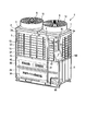
- the exterior of the outdoor unit 1 is formed with a cubic housing 2.
- the housing 2 includes front plates 3 and 4, right side plates 5, top plates 6 and 7, left side plates, back plates, and bottom plates.
- the front plates 3 and 4 excluding the top plates 6 and 7, the right side plate 5, the left side plate, the back plate, and the bottom plate are made of metal.
- the front plate 3 is divided into an upper front plate 3A and a lower front plate 3B in the vertical direction.
- the upper front plate 3A and the lower front plate 3B are detachable.
- the upper upper front plate 3A has a large number of rectangular vents (intake ports) 3a arranged vertically and horizontally.
- the front plate 4 is also divided into an upper front plate 4A and a lower front plate 4B in the vertical direction. These upper front plate 4A and lower front plate 4B are detachable.
- the upper front plate 4A has a large number of rectangular vents (intake ports) 4a arranged in the vertical direction.
- the right side plate 5 has a large number of rectangular vents (intake ports) 5a arranged vertically and horizontally.
- the left side plate also has a large number of ventilation holes (intake ports) arranged vertically and horizontally.
- the top plates 6 and 7 each have a circular exhaust port.
- Cylindrical fan housings 8 and 9 are formed so as to cover the exhaust ports of the upper surface plates 6 and 7, respectively.
- the interior of the housing 2 is divided into an upper heat exchange chamber 2A and a lower machine chamber 2B by an intermediate partition plate 2x.
- the heat exchange chamber 2A is closed by the upper front plate 3A and the upper front plate 4A.
- the machine room 2B is closed by a lower front plate 3B and a lower front plate 4B.
- the outdoor heat exchanger 10 and the outdoor fans 11 and 12 are accommodated in the heat exchange chamber 2A.
- the outdoor heat exchanger 10 is U-shaped in plan view, and is in the state of being close to these face plates along the left side plate, the upper front plates 3A and 4A, the right side plate 5 of the housing 2, and the intermediate partition plate 2x. It is placed on top.
- the space inside the outdoor heat exchanger 10 communicates with the fan housings 8 and 9 through the exhaust ports of the upper surface plates 6 and 7, and the outdoor fans 11 and 12 are arranged at positions corresponding to the fan housings 8 and 9. ing.
- the refrigeration cycle component 30 and the electrical component box 40 are accommodated in the machine room 2B.
- the refrigeration cycle component 30 is a generic term for a compressor, a four-way valve, a receiver tank, an accumulator, and the like.
- the electrical component box 40 contains a plurality of drive circuits for driving the compressor, the outdoor fans 11, 12, etc., and a circuit board 41. Operations such as replacement and repair of parts in the machine room 2B are performed by removing the lower front plates 3B and 4B.
- the communication unit 20 is located between the upper front plate 4A of the housing 2 and the outdoor heat exchanger 10 and at a position corresponding to, for example, the second vent 4a from the top among the vents 4a in the upper front plate 4A. Is placed.
- the height position of the second vent 4a from the top is substantially the eye level of the worker standing next to the housing 2.
- the communication unit 20 operates with power generated by electromagnetic induction when receiving an electric wave transmitted from the information terminal 100 when the information terminal 100 is close to a very short distance range of about 1 cm to 10 cm, for example.
- This is a non-contact data communication with the terminal 100 using a so-called NFC (Near Field Communication) technology, and as shown in FIG. 2, an antenna 21, a transmission / reception unit 22, a CPU 23, a memory 24, communication A circuit 25 is included.
- NFC Near Field Communication
- the antenna 21 transmits and receives radio waves to and from the adjacent information terminal 100.
- the transmission / reception unit 22 transmits / receives a signal through the antenna 21 and takes in the radio wave received by the antenna 21 as the operating power of the communication unit 20.
- the CPU 23 executes various processes for data communication.
- the memory 24 stores a program necessary for the control of the CPU 23 and temporarily stores reception data and transmission data.
- the communication circuit 25 performs data communication between the CPU 23 and the controller 42 via a signal line.
- the communication unit 20 also houses an outside air temperature sensor that detects the temperature of the outside air.
- the controller 42 controls the operation of the refrigeration cycle component 30 in the outdoor unit 1 and each of the drive circuits in cooperation with the indoor unit that constitutes the air conditioner together with the outdoor unit 1. It is mounted on the circuit board 41 in the machine room 2B.
- the power supply circuit 43 is connected to a commercial AC power supply 50 in the building via a power cable, and takes in the AC voltage of the commercial AC power supply 50 as operating power for the outdoor unit 1.
- the building where the commercial AC power supply 50 is installed can be easily entered by the user and the air conditioner administrator or service person, but no other person can enter.
- a building in which the commercial AC power supply 50 is installed is security-managed, and only a registered user, an air conditioner administrator, and a service person can enter. Therefore, the operation of turning on and off the commercial AC power supply 50 can be performed by the user and the administrator or service person of the air conditioner, but cannot be performed by any other third party.
- the controller 42 includes a first control unit 42a, a second control unit 42b, a third control unit 42c, a third control unit 42d, and a memory 42e as main functions related to data setting and diagnosis of the outdoor unit 1.
- the first control unit 42a allows the setting of data input from the information terminal 100 via the communication unit 20 only for a predetermined time t1s from turning on the outdoor unit 1 (turning on the commercial AC power supply 50). Specifically, the first control unit 42a accepts data input from the information terminal 100 via the communication unit 20 for a predetermined time t1s from when the outdoor unit 1 is turned on.
- the second control unit 42b executes a data setting process for setting the data as operation data for the outdoor unit 1. Note that the setting of the operation data is completed by update storage in the memory 42d.
- the third control unit 42 c diagnoses the state of the outdoor unit 1 and sends the diagnosis result via the communication unit 20.
- a diagnostic process for informing the information terminal 100 is executed.
- the fourth control unit 42d notifies the information terminal 100 via the communication unit 20 when the end of the predetermined time t1s is approaching, and issues a time extension instruction issued from the information terminal 100 in response to this notification.
- the predetermined time t1s is extended.
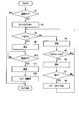
- the control executed by the controller 42 will be described with reference to the flowchart of FIG.
- the administrator or service person of the air conditioner transmits data related to the operation of the outdoor unit 1 to the outdoor unit.
- work which diagnoses what state the outdoor unit 1 is in is implemented.
- the administrator or service person of the air conditioner enters the building where the commercial AC power supply 50 is installed and turns on the commercial AC power supply 50.
- the air conditioner manager and serviceman are hereinafter referred to as workers.
- the controller 42 When the commercial AC power supply 50 is turned on (power on; YES in step S1), the controller 42 starts the time count t1 from zero (step S2), and the time count t1 and a predetermined time (initial value) set in advance. t1s is compared (step S3).
- the fixed time t1s includes a time sufficient for an operator to perform the work necessary for the data setting process and the diagnostic process, and is set to about 5 to 8 hours, for example.
- the controller 42 allows data setting processing and diagnosis processing based on data communication between the information terminal 100 and the communication unit 20 (step S4).
- This allowance allows the worker to perform the work necessary for the data setting process and the work necessary for the diagnosis process. That is, the worker approaches the upper front plate 4A of the housing 2 and brings the handheld information terminal 100 closer to the second vent hole 4a from the top of the upper front plate 4A. Then, the worker operates the information terminal 100 close to the vent 4a, and performs non-contact data communication between the information terminal 100 and the communication unit 20.
- the information terminal 100 for example, a tablet type information terminal or a smartphone type information terminal is used.
- the controller 42 receives data input from the information terminal 100 via the communication unit 20.
- the controller 42 executes a data setting process for setting the received data as operation data for the outdoor unit 1.
- the controller 42 diagnoses the state of the outdoor unit 1 and notifies the information terminal 100 of the diagnosis result via the communication unit 20. Execute the diagnostic process.
- the operation data set by the data setting process includes, for example, various parameters (outside air temperature, refrigerant temperature, compressor operating frequency, address codes of a plurality of indoor units, etc.) related to the operation of the outdoor unit 1 and the outdoor unit. 1 is a control program (firmware or the like) for controlling the operation of 1.
- the state diagnosed by the diagnostic process is, for example, the operation history of the outdoor unit 1, the failure content of the outdoor unit 1, and the like.
- the work for the data setting process and the work for the diagnosis process can be sufficiently completed within a predetermined time t1s if there is no problem in the progress of the work.
- the controller 42 determines whether or not the time count t1 has reached a predetermined time “t1s ⁇ ta” that is shorter than the predetermined time t1s by the time ⁇ ta, in accordance with the permission in step S4 (step S5).
- the time ⁇ ta is for notifying the worker that the time count t1 has approached the predetermined time t1s, and is about 5 minutes, for example.
- the controller 42 returns to step S3 and continues the comparison between the time count t1 and the predetermined time t1s.
- Step S5 When the time count t1 reaches the predetermined time “t1s ⁇ ta” (YES in step S5), the controller 42 notifies the information terminal 100 via the communication unit 20 that the processing allowable time is approaching ( Step S6). Receiving this notification, the information terminal 100 notifies the worker that the end of the processing allowable time is approaching by displaying an image or generating a buzzer sound. The worker who has received this notification determines whether the work being performed is completed by the end of the processing allowable time.
- the worker who has determined that the work being performed is not completed by the end of the work allowable time instructs the controller 42 to extend the time from the information terminal 100 via the communication unit 20.
- the controller 42 receives this time extension instruction (YES in step S7), the controller 42 updates and sets “t1s + ⁇ tb” obtained by adding the time ⁇ tb (> ⁇ ta) to the predetermined time t1s as a new predetermined time t1s (step S8). . ⁇ tb is, for example, 1 hour. Then, the controller 42 returns to step S3 and continues to compare the time count t1 with the new fixed time t1s.
- step S7 the controller 42 does not receive an instruction to extend the time (NO in step S7), the controller 42 returns to step S3 without updating the constant time t1s, and sets the time count t1 and the predetermined time (initial value) t1s. Continue to compare.
- step S3 When the time count t1 reaches the predetermined time t1s (YES in step S3), the controller 42 prohibits data setting processing based on data communication between the information terminal 100 and the communication unit 20 (step S9).
- the diagnosis process based on data communication between the information terminal 100 and the communication unit 20 may continue to be allowed or prohibited together with the data setting process.
- the outdoor unit 1 Data cannot be set for. Thereby, security and reliability against unauthorized access from a third party can be improved. Even if a third party tries to illegally change data already set for the outdoor unit 1, it can be prevented beforehand.
- the outdoor unit 1 is installed outdoors where anyone can approach, and data communication using NFC technology does not require a so-called coupling process for establishing communication with the information terminal 100.
- it is important to enhance the security against unauthorized access from a third party in order to ensure safe operation of the air conditioner and thus to ensure the reliability of the air conditioner.
- the time setting t1 reaches the predetermined time t1s and the data setting processing is prohibited while the worker is performing the work for the data setting processing.
- the worker has only to enter the building, cut off the commercial AC power supply 50 (power off), and then turn it on again (power on).
- the controller 42 monitors the interruption (power on) of the commercial AC power supply 50 in accordance with the prohibition of step S9 (YES in step S10).
- the controller 42 stores the processing content of the controller 42 immediately before the commercial AC power supply 50 is shut down in the memory 42d (step S11) and for a certain period of time.
- ts1 is returned to the initial value (step S12). Then, the controller 42 returns to step S1 and monitors power-on.
- step S1 When the commercial AC power supply 50 is turned on again (power is turned on) (YES in step S1), the controller 42 repeats the processing from step S2. In this case, the controller 42 continuously resumes the data setting process interrupted by the prohibition based on the processing content stored in the memory 42d. Thereby, the worker can complete the work for the data setting process.
- the radio wave transmitted from the information terminal 100 can be efficiently transmitted through the vent 4a without being obstructed by the upper front plate 4A that is a magnetic body.
- the radio wave transmitted from the communication unit 20 also efficiently reaches the information terminal 100 through the vent 4a without being obstructed by the upper front plate 4A that is a magnetic material.
- the worker only needs to operate the information terminal 100 by bringing the information terminal 100 close to the vent 4a, and the troublesome work of removing and reattaching the upper front plate 4A is unnecessary. Therefore, the burden on the worker can be reduced and the working time can be shortened.
- the communication unit 20 is disposed at a position corresponding to the second vent hole 4a from the top in the upper front plate 4A.
- the height position is not limited and can be appropriately selected.
- the fixed time t1s is set to, for example, about 5 to 8 hours has been described as an example.
- the fixed time t1s can be further increased depending on the type and number of the outdoor units 1 and the like. Can be selected as appropriate according to their experience and skill.
- the data setting process is prohibited after a certain time t1s from turning on the power.
- the data setting is performed after a certain time t1s from turning on the power.
- it may be configured to prohibit reading of data that is not desired to be viewed by a third party.
- the outdoor unit of the air conditioner is described as an example of the outdoor unit of the refrigeration cycle apparatus, but not only the outdoor unit of the air conditioner, for example, an air-cooled chilling unit, a heat source unit of a heat pump hot water supply device, It can also be applied to a heat source unit of a heat pump type heating device and a refrigerator connected to a freezing / refrigeration showcase.
Landscapes
- Engineering & Computer Science (AREA)
- Chemical & Material Sciences (AREA)
- Combustion & Propulsion (AREA)
- Mechanical Engineering (AREA)
- General Engineering & Computer Science (AREA)
- Signal Processing (AREA)
- Physics & Mathematics (AREA)
- Fuzzy Systems (AREA)
- Mathematical Physics (AREA)
- Human Computer Interaction (AREA)
- Computer Networks & Wireless Communication (AREA)
- Air Conditioning Control Device (AREA)
Abstract
Description
図1に示すように、室外機1は、立方体形の筐体2で外観が形成されている。筐体2は、前面板3,4、右側面板5、上面板6,7、左側面板、背面板、底面板を含む。上面板6,7を除く前面板3,4、右側面板5、左側面板、背面板、底面板が金属製である。
第1制御部42aは、情報端末100から通信ユニット20を介して入力されるデータの設定を当該室外機1の電源投入(商用交流電源50の投入)から一定時間t1sだけ許容する。具体的には、第1制御部42aは、情報端末100から通信ユニット20を介して入力されるデータを当該室外機1の電源投入から一定時間t1sだけ受付ける。
室外機1の設置時や移転時、あるいは空気調和装置に何らかのトラブルが発生した際の保守点検時、空気調和装置の管理者やサービスマンは、当該室外機1の運転に関わるデータを当該室外機1に対し設定する作業、あるいは室外機1がどのような状態にあるか診断する作業を実施する。この実施に際し、空気調和装置の管理者やサービスマンは、商用交流電源50が設置されている建物に入り、その商用交流電源50を投入する。なお、空気調和装置の管理者やサービスマンのことを、以下、作業員と称する。
Claims (6)
- 当該室外機に近接する情報端末との非接触のデータ通信を行う通信ユニットと、
前記情報端末から前記通信ユニットを介して入力されるデータの設定を当該室外機の電源投入から一定時間だけ許容するコントローラと、
を備えることを特徴とする室外機。 - 通気口を有する筐体と、
前記筐体内に収容された室外熱交換器と、
前記室外熱交換器を収容しその室外熱交換器に外気を通すための通気口を有する筐体と、
をさらに備え、
前記通信ユニットは、前記室外熱交換器における前記通気口と対応する位置に配置されている、
ことを特徴とする請求項1記載の室外機。 - 前記コントローラは、
前記情報端末から前記通信ユニットを介して入力されるデータを当該室外機の電源投入から前記一定時間だけ受付け、
前記受付けたデータが当該室外機の運転に関わるデータである場合に、そのデータを当該室外機の運転用データとして設定する、
ことを特徴とする請求項1記載の室外機。 - 前記コントローラは、
前記受付けたデータが当該室外機に対する診断の指示である場合に、当該室外機1がどのような状態にあるか診断し、その診断結果を前記通信ユニットを介して前記情報端末に報知する、
ことを特徴とする請求項3に記載の室外機。 - 前記コントローラは、
前記一定時間の終了が近づいた場合にその旨を前記通信ユニットを介して前記情報端末に通知し、この通知に応じて前記情報端末から発せられる時間延長の指示を前記通信ユニットを介して受けた場合に前記一定時間を延長する、
ことを特徴とする請求項1に記載の室外機。 - 前記通信ユニットは、前記情報端末から送信される電波を受けた際の電磁誘導により生じる電力で動作し、前記情報端末との間で近距離無線通信の技術による非接触のデータ通信を行う、
ことを特徴とする請求項1に記載の室外機。
Priority Applications (5)
| Application Number | Priority Date | Filing Date | Title |
|---|---|---|---|
| KR1020177016441A KR101933335B1 (ko) | 2014-11-19 | 2015-11-16 | 실외기 |
| CN201580062739.8A CN107076450B (zh) | 2014-11-19 | 2015-11-16 | 室外机 |
| JP2016560212A JPWO2016080353A1 (ja) | 2014-11-19 | 2015-11-16 | 室外機 |
| EP15861507.0A EP3222927B1 (en) | 2014-11-19 | 2015-11-16 | Outdoor unit |
| US15/594,161 US20170248336A1 (en) | 2014-11-19 | 2017-05-12 | Outdoor unit |
Applications Claiming Priority (2)
| Application Number | Priority Date | Filing Date | Title |
|---|---|---|---|
| JP2014234413 | 2014-11-19 | ||
| JP2014-234413 | 2014-11-19 |
Related Child Applications (1)
| Application Number | Title | Priority Date | Filing Date |
|---|---|---|---|
| US15/594,161 Continuation US20170248336A1 (en) | 2014-11-19 | 2017-05-12 | Outdoor unit |
Publications (1)
| Publication Number | Publication Date |
|---|---|
| WO2016080353A1 true WO2016080353A1 (ja) | 2016-05-26 |
Family
ID=56013890
Family Applications (1)
| Application Number | Title | Priority Date | Filing Date |
|---|---|---|---|
| PCT/JP2015/082135 Ceased WO2016080353A1 (ja) | 2014-11-19 | 2015-11-16 | 室外機 |
Country Status (6)
| Country | Link |
|---|---|
| US (1) | US20170248336A1 (ja) |
| EP (1) | EP3222927B1 (ja) |
| JP (2) | JPWO2016080353A1 (ja) |
| KR (1) | KR101933335B1 (ja) |
| CN (1) | CN107076450B (ja) |
| WO (1) | WO2016080353A1 (ja) |
Cited By (6)
| Publication number | Priority date | Publication date | Assignee | Title |
|---|---|---|---|---|
| JP2020148376A (ja) * | 2019-03-13 | 2020-09-17 | 株式会社富士通ゼネラル | 室外機 |
| JP2020193743A (ja) * | 2019-05-27 | 2020-12-03 | 三菱電機株式会社 | データ収集装置、無人航空機、データ収集システム、データ収集方法、運転状態データ取得方法及びプログラム |
| WO2020250793A1 (ja) | 2019-06-12 | 2020-12-17 | ダイキン工業株式会社 | 空気調和装置の室外機およびそれを備えた室外機システム |
| JP2021081089A (ja) * | 2019-11-14 | 2021-05-27 | 三菱電機株式会社 | 情報送信装置、機器、通信システム、通信方法及びプログラム |
| WO2022064936A1 (ja) * | 2020-09-23 | 2022-03-31 | 東芝キヤリア株式会社 | 空気調和機の室外機 |
| JPWO2024201730A1 (ja) * | 2023-03-28 | 2024-10-03 |
Families Citing this family (4)
| Publication number | Priority date | Publication date | Assignee | Title |
|---|---|---|---|---|
| BR112017010501B1 (pt) | 2014-11-18 | 2022-12-27 | Toshiba Carrier Corporation | Unidade externa |
| WO2017077647A1 (ja) * | 2015-11-06 | 2017-05-11 | 三菱電機株式会社 | 室外機及びそれを用いた空気調和装置 |
| KR102897314B1 (ko) * | 2019-11-08 | 2025-12-05 | 엘지전자 주식회사 | 공기조화시스템 및 공기조화시스템의 제어방법 |
| EP4163565B1 (en) * | 2021-10-05 | 2024-07-31 | Carrier Corporation | A near field communication device and system for attachment to an outdoor unit housing |
Citations (5)
| Publication number | Priority date | Publication date | Assignee | Title |
|---|---|---|---|---|
| JPH10111001A (ja) * | 1996-10-04 | 1998-04-28 | Mitsubishi Electric Corp | 特殊モード付き制御装置 |
| JP2003148790A (ja) * | 2001-11-12 | 2003-05-21 | Daikin Ind Ltd | 空気調和機 |
| JP2007322086A (ja) * | 2006-06-02 | 2007-12-13 | Hitachi Appliances Inc | 空気調和機及び空気調和機の室内機 |
| JP2013093766A (ja) * | 2011-10-26 | 2013-05-16 | Tokai Rika Co Ltd | 双方向通信システム |
| JP2013120035A (ja) * | 2011-12-08 | 2013-06-17 | Fujitsu General Ltd | 空気調和機 |
Family Cites Families (19)
| Publication number | Priority date | Publication date | Assignee | Title |
|---|---|---|---|---|
| JPS5197549A (ja) | 1975-02-26 | 1976-08-27 | Erekutorosuraguyosetsuho | |
| US5419165A (en) * | 1993-12-08 | 1995-05-30 | Perkins; Jon T. | Electrical panel locking apparatus |
| JPH0835713A (ja) * | 1994-07-26 | 1996-02-06 | Fujitsu General Ltd | 空気調和機の制御方法およびその装置 |
| US20040024846A1 (en) * | 2000-08-22 | 2004-02-05 | Stephen Randall | Method of enabling a wireless information device to access data services |
| US20040176022A1 (en) * | 2002-12-10 | 2004-09-09 | Steven Thrasher | Systems, methods and devices for controlling ventilation registers |
| JP2006132870A (ja) * | 2004-11-08 | 2006-05-25 | Fujitsu General Ltd | 空気調和機のメンテナンスシステム |
| JP4458486B2 (ja) * | 2005-08-02 | 2010-04-28 | 日立アプライアンス株式会社 | 空調システム及び空調管理装置 |
| JP3992065B2 (ja) * | 2006-02-01 | 2007-10-17 | ダイキン工業株式会社 | 電装品アセンブリ及びそれを備えた空気調和装置の室外ユニット |
| JP2008281231A (ja) * | 2007-05-08 | 2008-11-20 | Sharp Corp | 電気機器、空気調和機、室外機及び室内機 |
| JP2009237237A (ja) * | 2008-03-27 | 2009-10-15 | Brother Ind Ltd | プロジェクタ |
| KR20100123486A (ko) * | 2009-05-15 | 2010-11-24 | 엘지전자 주식회사 | 공기조화기 및 그 제어방법 |
| KR101622616B1 (ko) * | 2009-05-15 | 2016-05-20 | 엘지전자 주식회사 | 공기조화기 진단방법 및 이를 수행하는 휴대 단말 장치 |
| JP5197549B2 (ja) * | 2009-11-06 | 2013-05-15 | 三菱電機株式会社 | 設定診断システム |
| JP2011149674A (ja) * | 2010-01-25 | 2011-08-04 | Daikin Industries Ltd | 空気調和装置 |
| US8589733B2 (en) * | 2010-08-13 | 2013-11-19 | International Business Machines Corporation | Saving operational state of open applications when unexpected shutdown events occur |
| JP5168365B2 (ja) * | 2011-01-20 | 2013-03-21 | 株式会社富士通ゼネラル | 空気調和機 |
| JP5981733B2 (ja) * | 2012-03-05 | 2016-08-31 | キヤノン株式会社 | システムおよび制御方法 |
| JP6190617B2 (ja) * | 2013-04-22 | 2017-08-30 | 尼寺空圧工業株式会社 | エアーコンプレッサ |
| CN103884074B (zh) * | 2013-12-27 | 2017-03-29 | 广东美的制冷设备有限公司 | 空调无线控制器、空调器及其售后服务提供方法和系统 |
-
2015
- 2015-11-16 EP EP15861507.0A patent/EP3222927B1/en active Active
- 2015-11-16 CN CN201580062739.8A patent/CN107076450B/zh active Active
- 2015-11-16 JP JP2016560212A patent/JPWO2016080353A1/ja active Pending
- 2015-11-16 WO PCT/JP2015/082135 patent/WO2016080353A1/ja not_active Ceased
- 2015-11-16 KR KR1020177016441A patent/KR101933335B1/ko active Active
-
2017
- 2017-05-12 US US15/594,161 patent/US20170248336A1/en not_active Abandoned
-
2018
- 2018-08-29 JP JP2018160834A patent/JP6613349B2/ja active Active
Patent Citations (5)
| Publication number | Priority date | Publication date | Assignee | Title |
|---|---|---|---|---|
| JPH10111001A (ja) * | 1996-10-04 | 1998-04-28 | Mitsubishi Electric Corp | 特殊モード付き制御装置 |
| JP2003148790A (ja) * | 2001-11-12 | 2003-05-21 | Daikin Ind Ltd | 空気調和機 |
| JP2007322086A (ja) * | 2006-06-02 | 2007-12-13 | Hitachi Appliances Inc | 空気調和機及び空気調和機の室内機 |
| JP2013093766A (ja) * | 2011-10-26 | 2013-05-16 | Tokai Rika Co Ltd | 双方向通信システム |
| JP2013120035A (ja) * | 2011-12-08 | 2013-06-17 | Fujitsu General Ltd | 空気調和機 |
Non-Patent Citations (1)
| Title |
|---|
| See also references of EP3222927A4 * |
Cited By (11)
| Publication number | Priority date | Publication date | Assignee | Title |
|---|---|---|---|---|
| JP2020148376A (ja) * | 2019-03-13 | 2020-09-17 | 株式会社富士通ゼネラル | 室外機 |
| JP2020193743A (ja) * | 2019-05-27 | 2020-12-03 | 三菱電機株式会社 | データ収集装置、無人航空機、データ収集システム、データ収集方法、運転状態データ取得方法及びプログラム |
| JP7450345B2 (ja) | 2019-05-27 | 2024-03-15 | 三菱電機株式会社 | データ収集システム、データ収集方法及びプログラム |
| WO2020250793A1 (ja) | 2019-06-12 | 2020-12-17 | ダイキン工業株式会社 | 空気調和装置の室外機およびそれを備えた室外機システム |
| JP2021081089A (ja) * | 2019-11-14 | 2021-05-27 | 三菱電機株式会社 | 情報送信装置、機器、通信システム、通信方法及びプログラム |
| JP7466294B2 (ja) | 2019-11-14 | 2024-04-12 | 三菱電機株式会社 | 通信システム及び通信方法 |
| WO2022064936A1 (ja) * | 2020-09-23 | 2022-03-31 | 東芝キヤリア株式会社 | 空気調和機の室外機 |
| JPWO2022064936A1 (ja) * | 2020-09-23 | 2022-03-31 | ||
| JPWO2024201730A1 (ja) * | 2023-03-28 | 2024-10-03 | ||
| WO2024201730A1 (ja) * | 2023-03-28 | 2024-10-03 | 三菱電機株式会社 | 空気調和システム |
| JP7843913B2 (ja) | 2023-03-28 | 2026-04-10 | 三菱電機株式会社 | 空気調和システム |
Also Published As
| Publication number | Publication date |
|---|---|
| US20170248336A1 (en) | 2017-08-31 |
| EP3222927A4 (en) | 2018-07-18 |
| EP3222927B1 (en) | 2020-03-18 |
| JP2019011945A (ja) | 2019-01-24 |
| CN107076450A (zh) | 2017-08-18 |
| JPWO2016080353A1 (ja) | 2017-07-06 |
| EP3222927A1 (en) | 2017-09-27 |
| KR20170084292A (ko) | 2017-07-19 |
| CN107076450B (zh) | 2020-04-21 |
| JP6613349B2 (ja) | 2019-11-27 |
| KR101933335B1 (ko) | 2019-03-15 |
Similar Documents
| Publication | Publication Date | Title |
|---|---|---|
| JP6613349B2 (ja) | 冷凍サイクル装置の室外機 | |
| US10488072B2 (en) | Air conditioning system with leak protection control | |
| JP6364501B2 (ja) | 室外機 | |
| EP3896351B1 (en) | Air conditioner | |
| KR101629864B1 (ko) | 미세먼지 제거장치를 갖는 중앙제어식 원격제어 공기조화기 | |
| JP6572622B2 (ja) | 空調換気システム | |
| US20160028559A1 (en) | Systems and methods for communicating with electric motors | |
| JP6420908B2 (ja) | 室外機設定システム、室外機設定方法、及び室外機 | |
| KR101999214B1 (ko) | 고유식별정보 설정이 용이한 팬 필터 유닛 제어장치 | |
| JP2015075288A (ja) | 空気調和装置 | |
| CN113137692B (zh) | 中央空调的电控箱运行监控系统及其控制方法 | |
| JP7300053B2 (ja) | 冷凍サイクル装置および冷凍システム | |
| JP6714996B2 (ja) | ポンプ装置 | |
| TW202305296A (zh) | 通訊控制裝置、冷卻裝置 | |
| JP2015075287A (ja) | 空気調和装置 | |
| JP2023038672A (ja) | ネットワークシステム | |
| JP2022070759A (ja) | 機器システム及び機器システムの制御プログラム | |
| KR20100089654A (ko) | 멀티공기조화 시스템 및 그 제어방법 |
Legal Events
| Date | Code | Title | Description |
|---|---|---|---|
| 121 | Ep: the epo has been informed by wipo that ep was designated in this application |
Ref document number: 15861507 Country of ref document: EP Kind code of ref document: A1 |
|
| ENP | Entry into the national phase |
Ref document number: 2016560212 Country of ref document: JP Kind code of ref document: A |
|
| REEP | Request for entry into the european phase |
Ref document number: 2015861507 Country of ref document: EP |
|
| NENP | Non-entry into the national phase |
Ref country code: DE |
|
| ENP | Entry into the national phase |
Ref document number: 20177016441 Country of ref document: KR Kind code of ref document: A |