WO2016080513A1 - 歯車およびこれを備えた電動アクチュエータ - Google Patents
歯車およびこれを備えた電動アクチュエータ Download PDFInfo
- Publication number
- WO2016080513A1 WO2016080513A1 PCT/JP2015/082673 JP2015082673W WO2016080513A1 WO 2016080513 A1 WO2016080513 A1 WO 2016080513A1 JP 2015082673 W JP2015082673 W JP 2015082673W WO 2016080513 A1 WO2016080513 A1 WO 2016080513A1
- Authority
- WO
- WIPO (PCT)
- Prior art keywords
- gear
- nut
- housing
- electric motor
- output gear
- Prior art date
- Legal status (The legal status is an assumption and is not a legal conclusion. Google has not performed a legal analysis and makes no representation as to the accuracy of the status listed.)
- Ceased
Links
Images

Classifications
-
- B—PERFORMING OPERATIONS; TRANSPORTING
- B21—MECHANICAL METAL-WORKING WITHOUT ESSENTIALLY REMOVING MATERIAL; PUNCHING METAL
- B21D—WORKING OR PROCESSING OF SHEET METAL OR METAL TUBES, RODS OR PROFILES WITHOUT ESSENTIALLY REMOVING MATERIAL; PUNCHING METAL
- B21D53/00—Making other particular articles
- B21D53/26—Making other particular articles wheels or the like
- B21D53/28—Making other particular articles wheels or the like gear wheels
-
- F—MECHANICAL ENGINEERING; LIGHTING; HEATING; WEAPONS; BLASTING
- F16—ENGINEERING ELEMENTS AND UNITS; GENERAL MEASURES FOR PRODUCING AND MAINTAINING EFFECTIVE FUNCTIONING OF MACHINES OR INSTALLATIONS; THERMAL INSULATION IN GENERAL
- F16H—GEARING
- F16H55/00—Elements with teeth or friction surfaces for conveying motion; Worms, pulleys or sheaves for gearing mechanisms
- F16H55/02—Toothed members; Worms
- F16H55/14—Construction providing resilience or vibration-damping
-
- B—PERFORMING OPERATIONS; TRANSPORTING
- B23—MACHINE TOOLS; METAL-WORKING NOT OTHERWISE PROVIDED FOR
- B23P—METAL-WORKING NOT OTHERWISE PROVIDED FOR; COMBINED OPERATIONS; UNIVERSAL MACHINE TOOLS
- B23P15/00—Making specific metal objects by operations not covered by a single other subclass or a group in this subclass
- B23P15/14—Making specific metal objects by operations not covered by a single other subclass or a group in this subclass gear parts, e.g. gear wheels
-
- F—MECHANICAL ENGINEERING; LIGHTING; HEATING; WEAPONS; BLASTING
- F16—ENGINEERING ELEMENTS AND UNITS; GENERAL MEASURES FOR PRODUCING AND MAINTAINING EFFECTIVE FUNCTIONING OF MACHINES OR INSTALLATIONS; THERMAL INSULATION IN GENERAL
- F16H—GEARING
- F16H1/00—Toothed gearings for conveying rotary motion
-
- F—MECHANICAL ENGINEERING; LIGHTING; HEATING; WEAPONS; BLASTING
- F16—ENGINEERING ELEMENTS AND UNITS; GENERAL MEASURES FOR PRODUCING AND MAINTAINING EFFECTIVE FUNCTIONING OF MACHINES OR INSTALLATIONS; THERMAL INSULATION IN GENERAL
- F16H—GEARING
- F16H25/00—Gearings comprising primarily only cams, cam-followers and screw-and-nut mechanisms
- F16H25/18—Gearings comprising primarily only cams, cam-followers and screw-and-nut mechanisms for conveying or interconverting oscillating or reciprocating motions
- F16H25/20—Screw mechanisms
- F16H25/22—Screw mechanisms with balls, rollers, or similar members between the co-operating parts; Elements essential to the use of such members
- F16H25/2204—Screw mechanisms with balls, rollers, or similar members between the co-operating parts; Elements essential to the use of such members with balls
Definitions
- the present invention relates to a gear that suppresses the generation of abnormal noise and an electric actuator including the same, and an electric actuator including a ball screw mechanism used in a drive unit of a general industrial electric motor or automobile.
- the present invention relates to an electric actuator that converts rotational input from an electric motor into linear motion of a drive shaft via a ball screw mechanism.
- a gear mechanism such as a trapezoidal screw or a rack and pinion is generally used as a mechanism for converting the rotational motion of the electric motor into a linear linear motion. Since these conversion mechanisms involve a sliding contact portion, the power loss is large, and it is necessary to increase the size of the electric motor and increase the power consumption. For this reason, a ball screw mechanism has been adopted as a more efficient actuator with very low friction.
- the electric actuator 51 includes a housing 52 including a first housing 52a and a second housing 52b, an electric motor 53 attached to the housing 52, and a rotational force of the electric motor 53 via a motor shaft 53a.
- a transmission speed reduction mechanism 57 and a ball screw mechanism 58 that converts the rotational motion of the electric motor 53 into the linear motion in the axial direction of the drive shaft 59 via the speed reduction mechanism 57 are provided.
- a nut 61 that is rotatably supported through a pair of support bearings 66, 66 and is not movable in the axial direction, and has a helical thread groove 61 a formed on the inner periphery, and a number of nuts 61 are provided on the nut 61.
- a helical thread groove 60a that is inserted through the ball 62, is coaxially integrated with the drive shaft 59, and corresponds to the thread groove 61a of the nut 61 on the outer periphery. It is formed, and a a non-rotatable, and a screw shaft 60 which is axially movably supported relative to the housing 52.
- An electric motor 53 is attached to the first housing 52a, and a through hole 63a and a bag hole 63b for accommodating the screw shaft 60 are formed in the abutting portion of the first housing 52a and the second housing 52b.
- the speed reduction mechanism 57 includes an input gear 54 fixed to the motor shaft 53a, an intermediate gear 55 meshed with the input gear 54, and an output gear 56 meshed with the intermediate gear 55 and integrally fixed to the nut 61. I have.
- a gear shaft 64 is fitted into the first housing 52a and the second housing 52b, and between the gear shaft 64 and the intermediate gear 55 and between the first housing 52a, the second housing 52b, and the gear shaft 64.
- a synthetic resin bushing 65 is interposed in either or both of them, and the intermediate gear 55 is rotatably supported with respect to the housing 52.
- the rotational force of the electric motor 53 is transmitted to the nut 61 of the ball screw mechanism 58 through the speed reduction mechanism 57 including the input gear 54, the intermediate gear 55, and the output gear 56.
- the nut 61 is rotatably supported by a support bearing 66 composed of two deep groove ball bearings.
- An output gear 56 is disposed between the two support bearings 66, and the one support bearing 66 and the output gear 56 are fixed in contact with each other.
- a low noise gear 69 as shown in FIG. 6 is known as a gear that absorbs vibration.
- the low noise gear 69 includes a metal gear 72 including a core portion 70 and tooth portions 71 formed on the outer periphery in the radial direction of the core portion 70, and vibrations formed in the core portion 70 of the metal gear 72 by insert molding. And an absorbent material 73.
- Concave portions 74a and 74b are formed on both side surfaces of the core portion 70.
- the concave portions 74a and 74b are communicated with each other between the concave portions 74a and 74b, and a communication portion 74c having a smaller cross-sectional area than the concave portions 74a and 74b is formed.
- the vibration-absorbing material 73 is formed in the recessed part 74a, 74b and the communication part 74c in the shape which cannot detach
- the vibration absorbing material 73 there is a synthetic rubber having a damping effect, for example, heat resistance and oil resistance (see, for example, Patent Document 2).
- JP 2013-148108 A Japanese Patent Laid-Open No. 9-177943
- the vibration absorbing material 73 in the conventional low noise gear 69 shown in FIG. 6, it is possible to prevent the vibration absorbing material 73 from detaching from the core portion 70 of the metal gear 72 due to, for example, high speed rotation of the gear. Although it is possible to attenuate the generated vibration, since the vibration absorbing material 73 is sandwiched in the radial direction of the gear, the rigidity in the rotational direction of the vibration absorbing material 73 portion is large when transmitting a large torque. There is a problem that the desired amount of rotation of the motor is not obtained due to the elastic change of the vibration absorbing material 73, and the amount of elastic change varies depending on the magnitude of the load load.
- the vibration absorbing material 73 interferes with the outer ring 68 and smooth rotation motion of the output gear 56 is caused. Therefore, it is difficult to achieve both weight reduction and vibration isolation.
- the present invention has been made in view of such problems of the prior art, and focuses on a structure that vulcanizes the vibration absorbing material in the lightening portion to prevent falling off and prevents contact with the outer ring, and is lightweight.
- a gear and an electric actuator provided with the gear that can suppress the generation of abnormal noise by damping the vibration generated on the tooth surface when the gear meshes and ensure smooth rotation of the gear.
- the invention according to claim 1 of the present invention includes a tooth portion on the outer periphery and a circular hole on the inner periphery, an outer diameter portion in the vicinity of the tooth portion, and a portion in the vicinity of the circular hole.
- the central part between the boss part is formed thinner than the outer diameter part and the width of the boss part, and the hollow part is formed in the central part at equal intervals in the circumferential direction.
- the vibration absorbing material made of synthetic rubber is integrally joined to the outer peripheral side of the adjacent bearing on both side surfaces of the central portion.
- a tooth part is formed on the outer periphery and a circular hole is formed on the inner periphery, and the central part between the outer diameter part in the vicinity of the tooth part and the boss part in the vicinity of the circular hole is larger than the width of the outer diameter part or the boss part.
- the bearing is formed with a thin wall, and a hollow hole is formed in the central portion at equal intervals in the circumferential direction, and a vibration absorbing material made of synthetic rubber is adjacent to both side surfaces of the central portion through the hollow hole.
- the generated vibration can be attenuated to suppress the generation of unpleasant noises such as an unpleasant rattling noise, and contact with the outer ring of the bearing can be prevented to ensure a smooth rotational movement of the gear.
- the rotational inertia of the gear can be reduced, and the strength and durability are improved. be able to.
- the hollow hole is formed in a rectangular shape or a triangular shape whose width is increased outward in the radial direction, a large extraction amount is ensured and a light weight is ensured. Can be achieved.
- the vibration absorbing material is molded. Can be facilitated and desired dimensional accuracy can be ensured.
- the gear is made of a sintered alloy as in the invention described in claim 5, even if the gear has a high workability and a complicated shape, it can be easily and accurately formed into a desired shape and size. can do.
- a housing an electric motor attached to the housing, a reduction mechanism for transmitting the rotational force of the electric motor via a motor shaft, and the reduction mechanism.
- a ball screw mechanism that converts the rotational motion of the electric motor into a linear motion in the axial direction of the drive shaft via the bearing, and the ball screw mechanism is rotatable via a support bearing mounted on the housing, and
- An output gear constituting the speed reduction mechanism is supported on the outer periphery so as not to move in the axial direction, and a nut having a helical thread groove formed on the inner periphery, and the nut is inserted through a number of balls
- An electric actuator comprising a screw shaft which is formed on the outer periphery with a spiral screw groove corresponding to the screw groove of the nut and is supported so as not to rotate with respect to the housing and to be movable in the axial direction.
- the output gear is fixed to the outer peripheral surface of the nut in a state of being sandwiched between the inner ring of the support bearing and the flange portion of the nut, and the output gear is a gear according to any one of claims 1 to 5. It is configured.
- a reduction mechanism that transmits the rotational force of the electric motor, and a ball screw mechanism that converts the rotational movement of the electric motor into a linear movement in the axial direction of the drive shaft via the reduction mechanism.
- a nut that is rotatably supported through a support bearing mounted on the housing and is not movable in the axial direction, and has a helical thread groove formed on the inner periphery, and the nut is inserted through a number of balls.
- An output gear in an electric actuator comprising a screw shaft that is formed on the outer periphery and has a helical screw groove corresponding to the screw groove of the nut, and is supported so as not to rotate with respect to the housing and to be movable in the axial direction.
- An electric actuator that prevents contact and prevents the generation of noise by attenuating vibration generated on the tooth surface when meshing the output gear while ensuring smooth rotation of the output gear and reducing weight. Can be provided.
- a tooth portion is formed on the outer periphery and a circular hole is formed on the inner periphery, and a central portion between the outer diameter portion in the vicinity of the tooth portion and the boss portion in the vicinity of the circular hole is the outer diameter portion.
- the thickness of the boss is thinner than the width of the boss, and the center part is formed with uniform holes in the circumferential direction.
- the vibrations are made of synthetic rubber on both sides of the center part through the hole. Since the absorber is integrally joined to the outer peripheral side rather than the outer diameter of the adjacent bearing, it is possible to prevent the vibration absorber from peeling off and to drop off, and to improve the reliability, while reducing the weight of the gear. When meshing, the vibration generated on the tooth surface can be attenuated to suppress the generation of unpleasant rattling noises and other noise, preventing contact with the outer ring of the bearing and ensuring smooth rotation of the gears. can do.
- An electric actuator includes a housing, an electric motor attached to the housing, a reduction mechanism that transmits the rotational force of the electric motor via a motor shaft, and the electric actuator via the reduction mechanism.
- a ball screw mechanism that converts the rotational motion of the motor into a linear motion in the axial direction of the drive shaft, and the ball screw mechanism is rotatable via a support bearing mounted on the housing and cannot be moved in the axial direction.
- An output gear constituting the speed reduction mechanism is fixed to the outer periphery, a nut having a spiral thread groove formed on the inner periphery, and a nut inserted into the nut via a number of balls.
- An electric actuator comprising a screw shaft formed with a helical screw groove corresponding to the screw groove and supported so as not to rotate with respect to the housing and to be movable in the axial direction
- the output gear is constituted by the gear according to any one of claims 1 to 5, and is fixed to the outer peripheral surface of the nut while being sandwiched between the inner ring of the support bearing and the flange portion of the nut. Therefore, contact with the outer ring of the support bearing is prevented to ensure smooth rotation of the output gear, and while reducing weight, the vibration generated on the tooth surface when the output gear is engaged is attenuated.
- An electric actuator that suppresses the generation of sound can be provided.
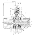
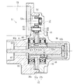
- FIG. 1 is a longitudinal section showing one embodiment of an electric actuator concerning the present invention. It is a longitudinal cross-sectional view which expands and shows the ball screw mechanism of FIG.
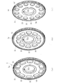
- (A) is a perspective view showing a hollow shape of a gear according to the present invention
- (b) is a perspective view showing a comparative example of (a)
- (c) is a perspective view showing another comparative example.
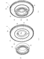
- (A) is explanatory drawing which shows the attachment relationship of the gearwheel and support bearing which concern on this invention
- (b) is a perspective view which shows the attachment state of a gearwheel and a support bearing.
- An aluminum alloy housing An electric motor attached to the housing, a reduction mechanism that transmits the rotational force of the electric motor via a motor shaft, and the rotational movement of the electric motor is driven via the reduction mechanism
- a ball screw mechanism for converting the shaft into a linear motion in the axial direction, and the ball screw mechanism is supported by a support bearing attached to the housing so as to be rotatable and non-movable in the axial direction.
- An output gear constituting the speed reduction mechanism is fixed, a nut having a spiral thread groove formed on the inner periphery, and a spiral corresponding to the thread groove of the nut is inserted into the nut via a large number of balls.
- the electric actuator that is formed of a screw shaft that is formed so as to be non-rotatable with respect to the housing and is supported so as to be movable in the axial direction. It is fixed to the outer peripheral surface of the nut in a state of being sandwiched between the inner ring of the support bearing and the flange of the nut, and has a tooth portion on the outer periphery and a circular hole in the inner periphery, and an outer diameter portion in the vicinity of the tooth portion. And a boss portion in the vicinity of the circular hole is formed thinner than the outer diameter portion and the width of the boss portion, and the width of the rectangular portion is increased radially outward at the center portion. Shaped hollow holes are formed at equal intervals in the circumferential direction, and vibration absorbing materials made of synthetic rubber are added to the outer peripheral side of the outer diameter of the support bearing on both side surfaces of the central portion through the hollow holes. They are joined together by sulfur.
- FIG. 1 is a longitudinal sectional view showing an embodiment of an electric actuator according to the present invention
- FIG. 2 is an enlarged longitudinal sectional view showing the ball screw mechanism of FIG. 1
- FIG. 3 (a) is according to the present invention.
- FIG. 4B is a perspective view showing a hollow shape of a gear
- FIG. 4B is a perspective view showing a comparative example of FIG. 4A
- FIG. 4C is a perspective view showing another comparative example
- FIG. Explanatory drawing which shows the attachment relationship of the gearwheel and support bearing which concerns on invention
- (b) is a perspective view which shows the attachment state of a gearwheel and a support bearing.
- an electric actuator 1 includes a cylindrical housing 2, an electric motor M attached to the housing 2, and a spur gear fixed to a motor shaft 3a of the electric motor M.
- a speed reduction mechanism 6 including an input gear 3, an intermediate gear 4 that meshes with the input gear 3, and an output gear 5 that meshes with the intermediate gear 4 and is fixed to an outer diameter of a nut 18 to be described later.
- a ball screw mechanism 8 that converts the rotational motion of the electric motor M into the axial motion of the drive shaft 7 via the mechanism 6 is provided.
- the housing 2 is formed by die casting from an aluminum alloy such as A6063TE or ADC12, and includes a first housing 2a to which the electric motor M is attached, and a second housing 2b abutted on the end face.
- the first housing 2a and the second housing 2b are integrally fixed by a fixing bolt (not shown).
- Each of the first housing 2a and the second housing 2b is formed with a through hole 11 and a bag hole 12 for accommodating a screw shaft 10 to be described later.
- the motor shaft 3a of the electric motor M is rotatably supported by a rolling bearing 13 composed of a deep groove ball bearing mounted on the second housing 2b. Yes.
- the output gear 5 that meshes with the intermediate gear 4 that is a spur gear is integrally fixed to a nut 18 that constitutes the ball screw mechanism 8 via a key 14.
- the drive shaft 7 is configured integrally with a screw shaft 10 constituting the ball screw mechanism 8, and locking pins 15 and 15 are implanted at one end portion (right end portion in the figure) of the drive shaft 7.
- a sleeve 17 is fitted into the bag hole 12 of the second housing 2b, and concave grooves 17a and 17a extending in the axial direction are formed on the inner periphery of the sleeve 17 by grinding.
- the concave grooves 17a and 17a are arranged opposite to each other in the circumferential direction, and the locking pins 15 and 15 of the screw shaft 10 are engaged with the concave grooves 17a and 17a, respectively, so that the screw shaft 10 cannot rotate.
- And is supported so as to be movable in the axial direction.
- the sleeve 17 is prevented from coming off in the axial direction by a retaining ring 9 for a hole attached to the opening of the bag hole 12 of the second housing 2b.
- the sleeve 17 is made of a sintered alloy prepared by adjusting a metal powder into a plastic shape and molding with an injection molding machine.
- metal powder and a binder made of plastic and wax are kneaded by a kneader, and the kneaded product is granulated into pellets.
- the granulated pellets are molded by so-called MIM (Metal Injection Molding), which is supplied to a hopper of an injection molding machine and pushed into a mold in a heated and melted state.
- MIM Metal Injection Molding
- the locking pin 15 that engages with the concave groove 17a is formed of high carbon chromium bearing steel such as SUJ2 or carburized bearing steel such as SCr435, and the surface thereof has a carbon content of 0.80 wt% or more and 58 HRC or more.
- the carbonitriding layer is formed.
- a surface hardness of 58HRC or more can be obtained, the wear resistance is excellent, the availability is good, and the cost is low. Can be achieved.
- the ball screw mechanism 8 includes a screw shaft 10 and a nut 18 externally inserted through the ball 19 to the screw shaft 10 as shown in an enlarged view in FIG.
- the screw shaft 10 has a spiral thread groove 10a formed on the outer periphery.
- the nut 18 is formed with a helical thread groove 18a corresponding to the thread groove 10a of the screw shaft 10 on the inner periphery, and a large number of balls 19 are accommodated between these thread grooves 10a and 18a so as to be able to roll. ing.
- the nut 18 is supported to the housings 2a and 2b via the two support bearings 20 and 20 so as to be rotatable and not movable in the axial direction.
- Reference numeral 21 denotes a piece member that constitutes a circulation member by connecting the thread grooves 18a of the nut 18, and the piece member 21 allows an infinite circulation of a large number of balls 19.
- each of the thread grooves 10a and 18a may be a circular arc shape or a Gothic arc shape.
- the Gothic can have a large contact angle with the ball 19 and a small axial clearance. It is formed in an arc shape. Thereby, the rigidity with respect to an axial load becomes high and generation
- the nut 18 is made of case-hardened steel such as SCM415 or SCM420, and its surface is hardened in the range of 55 to 62HRC by vacuum carburizing and quenching. Thereby, the buffing etc. for the scale removal after the heat treatment can be omitted, and the cost can be reduced.
- the screw shaft 10 is made of medium carbon steel such as S55C or case-hardened steel such as SCM415 or SCM420, and the surface thereof is hardened in the range of 55 to 62 HRC by induction hardening or carburizing hardening.
- An output gear 5 constituting the speed reduction mechanism 6 is fixed to the outer peripheral surface 18b of the nut 18 via a key 14, and two support bearings 20 and 20 are press-fitted on both sides of the output gear 5 via a predetermined squeeze.
- the key groove 14a is formed on the outer peripheral surface 18b of the nut 18, and the key groove 32a is also formed on the inner peripheral surface of the output gear 5, and a rectangular space formed by both the key grooves 14a and 32a.
- the output gear 5 is fixed to the nut 18 while being sandwiched between the inner ring 23 of the support bearing 20 on the first housing 2a side and the flange portion 18c of the nut 18.
- the support bearing 20 on the second housing 2b side is fixed to the nut 18 while being sandwiched between the flange portion 18c of the nut 18 and the second housing 2b.
- the two support bearings 20 and 20 are constituted by sealed deep groove ball bearings having shield plates 20a and 20a attached to both ends, and leakage of the lubricating grease enclosed in the bearings to the outside and from the outside This prevents wear powder from entering the bearing.
- the pair of support bearings 20, 20 that rotatably support the nut 18 are constituted by deep groove ball bearings having the same specifications, so that the thrust load and the output gear 5 are loaded from the drive shaft 7 described above.
- the deep groove ball bearings having the same specifications refer to bearings having the same inner diameter, outer diameter, width dimension, rolling element size, number, bearing internal clearance, and the like.
- the pair of support bearings 20 and 20 are fitted and inserted into the first housing 2a and the second housing 2b through radial clearances, respectively, and one of the pair of support bearings 20 and 20 is one support bearing 20. It is attached to the first housing 2a via a washer 22 made of a ring-shaped elastic member.
- the washer 22 was formed by press working from an austenitic stainless steel sheet (JIS standard SUS304 system or the like) having high strength and wear resistance or a rust-proof cold rolled steel sheet (JIS standard SPCC system or the like). Consists of wave washers.
- the inner diameter D is formed to be larger than the outer diameter d of the inner ring 23 of the support bearing 20, and the support bearing 20 is pressed against the adjacent output gear 5 side.
- the axial backlash of the pair of support bearings 20 and 20 can be eliminated, smooth rotation performance can be obtained, and the washer 22 abuts only on the outer ring 24 of the support bearing 20 to become a rotating ring.
- the gear shaft 25 of the intermediate gear 4 constituting the speed reduction mechanism 6 is implanted in the first and second housings 2 a and 2 b, and the intermediate gear 4 is connected to the gear shaft via a rolling bearing 26. 25 is rotatably supported.
- the end portions of the gear shaft 25 for example, when the end portion on the first housing 2 a side is press-fitted, the end portion on the second housing 2 b side is set to a clearance fit, thereby making misalignment (assembly error). Allowing smooth rotation performance can be ensured.
- the rolling bearing 26 includes a so-called steel plate outer ring 27 press-fitted into the inner diameter of the intermediate gear 4, and a plurality of needle rollers 29 accommodated in the outer ring 27 via a cage 28 so as to be freely rollable. It consists of a shell-type needle roller bearing. Thereby, the availability of a bearing is high and cost reduction can be achieved.
- ring-shaped washers 30 and 30 are mounted on both sides of the intermediate gear 4 to prevent the intermediate gear 4 from directly contacting the first and second housings 2a and 2b.
- the width of the tooth portion 4a of the intermediate gear 4 is formed smaller than the tooth width.
- the washer 30 is a flat washer formed by press working from an austenitic stainless steel plate having high strength and high wear resistance, or a cold-rolled steel plate treated with rust.
- it is formed of a thermoplastic synthetic resin such as PA (polyamide) 66 filled with a predetermined amount of a fibrous reinforcing material such as brass, sintered metal, or GF (glass fiber). May be.
- the output gear 5 is made of a sintered alloy. As shown in FIG. 3A, a tooth portion 5a made of spur teeth is formed on the outer periphery, and a circular hole 5b fitted to the outer peripheral surface 18b of the nut 18 is formed. Is formed. A central portion 33 between the outer diameter portion 31 in the vicinity of the tooth portion 5a and the boss portion 32 in the vicinity of the circular hole 5b is formed thinner than the width of the outer diameter portion 31 or the boss portion 32. In addition, a plurality of rectangular hollow holes 34 whose width dimension is increased outward in the radial direction are formed at equal intervals in the circumferential direction.
- a key groove 32 a into which the above-described fixing key 14 is inserted is formed on the inner periphery of the cylindrical boss portion 32.
- the hollow hole 34 is illustrated as a rectangular shape so that a large amount can be secured and the weight can be reduced.
- the present invention is not limited to this, and the weight and weight of the output gear 5 can be secured while ensuring.
- it may be formed in an egg shape (oval shape) or a triangular shape whose width dimension increases outward in the radial direction.
- Fe, Mo, Ni complete alloy powder iron powder atomized from alloyed molten steel, iron powder with a uniform alloy component in the particle
- partial alloy powder pure Alloy powder in which alloy powder is partially alloyed and adhered around iron powder.
- a hybrid alloy steel powder (trade name; JFE Steel) in which fine Ni powder, Cu powder, and graphite powder are adhered to a pre-alloyed copper powder of 2 wt% Fe, 1 wt% Mo composition, and Mo with a binder.
- JFE Steel Japanese Patent Application Lad
- the metal powder may be adjusted to a plastic shape and formed of a sintered alloy formed by MIM.
- the lightening hole 34 of the output gear 5 is set on the outer peripheral side.
- the rotation inertia (moment of inertia) proportional to the square of the radius of the output gear 5 is reduced rather than setting the lightening hole 34 on the inner peripheral side near the boss portion 32.
- Strength and durability can be improved.
- the vibration absorbing material 35 is integrally joined to the central portion 33 formed through a thin hole 34 through the hollow hole 34 of the output gear 5 by vulcanization adhesion.
- the vibration absorbing material 35 is made of synthetic rubber such as NBR (acrylonitrile-butadiene rubber) and is joined to the outer peripheral side of the outer diameter of the outer ring 24 of the adjacent support bearing 20 as shown in FIG. .
- the side surfaces of the vibration absorbing material 35 are set to be substantially flush with the width surfaces of the outer diameter portion 31 and the boss portion 32. Thereby, the vibration absorbing material 35 can be easily molded and desired dimensional accuracy can be ensured.
- the vibration absorbing material 35 penetrates the lightening hole 34 and is joined to both side surfaces of the central portion 33, the vibration absorbing material 35 can be prevented from being peeled off or dropped off, and the reliability can be improved.
- the generation of noise such as an unpleasant rattling noise can be suppressed by attenuating the vibration generated on the tooth surface 5a when the output gear 5 is engaged, as shown in FIG.
- the contact with the outer ring 24 can be prevented and the smooth rotation motion of the output gear 5 can be ensured.
- the term “substantially flush” means, for example, a design target value that is substantially free of steps, that is, a step caused by a processing error or the like should be allowed.
- the material of the vibration absorber 35 in addition to the above-mentioned NBR, for example, HNBR (hydrogenated acrylonitrile-butadiene rubber), EPM, EPDM, etc. having excellent heat resistance, ACM (Excellent heat resistance and chemical resistance) Examples thereof include polyacrylic rubber) and FKM (fluoro rubber).
- a gear according to the present invention is used in a drive unit of a general industrial electric motor, an automobile, and the like, and includes a ball screw mechanism that converts rotational input from an electric motor into linear motion of a drive shaft via the ball screw mechanism. It can be applied to the output gear of an electric actuator.
Landscapes
- Engineering & Computer Science (AREA)
- General Engineering & Computer Science (AREA)
- Mechanical Engineering (AREA)
- Gear Transmission (AREA)
- Gears, Cams (AREA)
- Transmission Devices (AREA)
Abstract
軽量化を図りつつ、歯車の噛合い時、歯面に発生する振動を減衰させて異音の発生を抑制して歯車の円滑な回転運動を確保した歯車およびこれを備えた電動アクチュエータを提供する。 電動モータMの回転力を伝達する減速機構6と、これを介して電動モータMの回転運動を駆動軸7の直線運動に変換するボールねじ機構8を備えた電動アクチュエータにおいて、出力歯車5が、支持軸受20の内輪23とナット18の鍔部18cとで挟持された状態でナット18の外周面に固定され、外径部31とボス部32の間の中央部33が薄肉に形成されると共に、この中央部33に径方向外方に向って幅寸法が拡大する矩形状の肉抜き穴34が周方向等配に形成され、これらの肉抜き穴34を貫通して中央部33の両側面に合成ゴムからなる振動吸収材35が支持軸受20の外径よりも外周側に加硫により一体に接合されている。
Description
本発明は、異音の発生を抑制した歯車およびこれを備え、一般産業用の電動機、自動車等の駆動部に使用されるボールねじ機構を備えた電動アクチュエータ、詳しくは、自動車のトランスミッションやパーキングブレーキ等で、電動モータからの回転入力を、ボールねじ機構を介して駆動軸の直線運動に変換する電動アクチュエータに関するものである。
各種駆動部に使用される電動アクチュエータにおいて、電動モータの回転運動を軸方向の直線運動に変換する機構として、台形ねじあるいはラックアンドピニオン等の歯車機構が一般的に使用されている。これらの変換機構は、滑り接触部を伴うため動力損失が大きく、電動モータの大型化や消費電力の増大を余儀なくされている。そのため、摩擦が非常に低く、より効率的なアクチュエータとしてボールねじ機構が採用されるようになってきた。
ボールねじ機構を採用した電動アクチュエータとして、例えば、図5に示すような構造が知られている。この電動アクチュエータ51は、第1のハウジング52aと第2のハウジング52bからなるハウジング52と、このハウジング52に取り付けられた電動モータ53と、この電動モータ53の回転力を、モータ軸53aを介して伝達する減速機構57と、この減速機構57を介して電動モータ53の回転運動を駆動軸59の軸方向の直線運動に変換するボールねじ機構58とを備え、このボールねじ機構58が、ハウジング52に装着された一対の支持軸受66、66を介して回転可能に、かつ軸方向移動不可に支持され、内周に螺旋状のねじ溝61aが形成されたナット61と、このナット61に多数のボール62を介して内挿され、駆動軸59と同軸状に一体化され、外周にナット61のねじ溝61aに対応する螺旋状のねじ溝60aが形成され、ハウジング52に対して回転不可に、かつ軸方向移動可能に支持されたねじ軸60とで構成されている。
第1のハウジング52aには電動モータ53が取り付けられ、第1のハウジング52aと第2のハウジング52bの衝合部にねじ軸60を収容するための貫通孔63aと袋孔63bが形成されると共に、減速機構57が、モータ軸53aに固定された入力歯車54と、この入力歯車54に噛合する中間歯車55と、この中間歯車55に噛合し、ナット61に一体に固定された出力歯車56を備えている。
また、第1のハウジング52aと第2のハウジング52bに歯車軸64が嵌挿され、この歯車軸64と中間歯車55との間および第1のハウジング52aと第2のハウジング52bと歯車軸64との間のどちらか一方、あるいは両方に合成樹脂製のブッシュ65が介装され、中間歯車55がハウジング52に対して回転自在に支承されている。これにより、中間歯車55と歯車軸64間のガタによる振動伝播を遮断して低減させると共に、歯車軸64自体のガタによる低騒音を実現させた電動アクチュエータ51を提供することができる。
この電動アクチュエータ51では、電動モータ53の回転力が、入力歯車54と中間歯車55および出力歯車56からなる減速機構57を介してボールねじ機構58のナット61に伝達される。このナット61は2つの深溝玉軸受からなる支持軸受66によって回転自在に支持されている。そして、これらの2つの支持軸受66間に出力歯車56が配置され、一方の支持軸受66と出力歯車56とは接触した状態で固定されている。
この場合、内輪67はナット61の外周面61bに固定されているため、ナット61と一体に回転するが、外輪68は第1のハウジング52aに嵌合されているため回転しない。したがって、出力歯車56の側面と支持軸受66の外輪68の端面とが接触すると、出力歯車56の円滑な回転運動が損なわれるため、内輪67と接触する出力歯車56のボス部56aを除き、歯先方向に向かって歯幅が薄く形成され、出力歯車56の軽量化を図ると共に外輪68との接触を防止している(例えば、特許文献1参照。)。
こうした従来の電動アクチュエータ51では、トルク伝達をする減速機構57の入力歯車54、中間歯車55および出力歯車56間に存在するバックラッシによって耳障りな歯打ち音等の異音が発生することがある。この歯打ち音は、例えば、出力歯車56の歯車本体を介してボールねじ機構58等の他部品に伝わり、最終的には装置全体を共振させてしまう。このような異音の発生を防止するために、振動を吸収する歯車として、図6に示すような低騒音歯車69が知られている。この低騒音歯車69は、心部70と、心部70の径方向外周上に形成される歯部71とからなる金属歯車72と、インサート成形により金属歯車72の心部70に形成される振動吸収材73とを備えている。
心部70の両側面には凹部74a、74bが形成され、凹部74a、74bの間に凹部74a、74b同士を連通させると共に、凹部74a、74bより断面積の小さい連通部74cが形成されている。そして、凹部74a、74bおよび連通部74cに振動吸収材73が、心部70から離脱不能な形状で形成されている。振動吸収材73としては、減衰効果のある、例えば、耐熱、耐油性を有する合成ゴムがある(例えば、特許文献2参照。)。
然しながら、こうした図6に示す従来の低騒音歯車69では、歯車の高速回転時等により、振動吸収材73が金属歯車72の心部70から離脱するのを防止することができ、歯部71に発生する振動を減衰させることは可能であるが、歯車の径方向に振動吸収材73が挟まれた形態であるので、大きなトルクを伝達する場合に、振動吸収材73部の回転方向の剛性が不足し、所望するモータの回転量が振動吸収材73の弾性変化によって得られず、負荷荷重の大きさによっても弾性変化量が異なるため、安定した位置決め精度が出ないという問題が生じる。
さらに、この低騒音歯車69を前述した図5に示すような支持軸受66に隣接した出力歯車56に適用した場合、振動吸収材73が外輪68と干渉し、出力歯車56の円滑な回転運動が損なわれるため、軽量化と防振性の両立を図ることが困難になる。
本発明は、こうした従来技術の問題点に鑑みてなされたものであり、振動吸収材を肉抜き部に加硫して脱落を防止すると共に、外輪との接触を防止する構造に着目し、軽量化を図りつつ、歯車の噛合い時、歯面に発生する振動を減衰させて異音の発生を抑制して歯車の円滑な回転運動を確保した歯車およびこれを備えた電動アクチュエータを提供することを目的とする。
係る目的を達成すべく、本発明のうち請求項1に記載の発明は、外周に歯部と内周に円孔が形成され、前記歯部の近傍の外径部と前記円孔の近傍のボス部との間の中央部が前記外径部やボス部の幅より薄肉に形成されると共に、当該中央部に肉抜き穴が周方向等配に形成され、これらの肉抜き穴を貫通して前記中央部の両側面に合成ゴムからなる振動吸収材が隣接する軸受の外径よりも外周側に一体に接合されている。
このように、外周に歯部と内周に円孔が形成され、歯部の近傍の外径部と円孔の近傍のボス部との間の中央部が外径部やボス部の幅より薄肉に形成されると共に、当該中央部に肉抜き穴が周方向等配に形成され、これらの肉抜き穴を貫通して中央部の両側面に合成ゴムからなる振動吸収材が隣接する軸受の外径よりも外周側に一体に接合されているので、振動吸収材の剥がれや脱落を防止して信頼性を高めることができると共に、軽量化を図りつつ、歯車の噛合い時、歯面に発生する振動を減衰させて不快な歯打ち音等の異音の発生を抑制することができ、軸受の外輪との接触を防止して歯車の円滑な回転運動を確保することができる。
好ましくは、請求項2に記載の発明のように、前記肉抜き穴が前記中央部の外周側に形成されていれば、歯車の回転イナーシャを低減させることができ、強度・耐久性を向上させることができる。
また、請求項3に記載の発明のように、前記肉抜き穴が径方向外方に向って幅寸法が拡大する矩形状または三角形状に形成されていれば、抜き量を大きく確保して軽量化を図ることができる。
また、請求項4に記載の発明のように、前記振動吸収材の側面が前記歯車の外径部やボス部の幅面と略面一になるように設定されていれば、振動吸収材の成形が容易になると共に、所望の寸法精度を確保することができる。
また、請求項5に記載の発明のように、前記歯車が焼結合金から形成されていれば、加工度が高く複雑な形状であっても容易に、かつ精度良く所望の形状・寸法に成形することができる。
また、本発明のうち請求項6に記載の発明は、ハウジングと、このハウジングに取り付けられた電動モータと、この電動モータの回転力を、モータ軸を介して伝達する減速機構と、この減速機構を介して前記電動モータの回転運動を駆動軸の軸方向の直線運動に変換するボールねじ機構とを備え、このボールねじ機構が、前記ハウジングに装着された支持軸受を介して回転可能に、かつ軸方向移動不可に支持され、外周に前記減速機構を構成する出力歯車が固定され、内周に螺旋状のねじ溝が形成されたナットと、このナットに多数のボールを介して内挿され、外周に前記ナットのねじ溝に対応する螺旋状のねじ溝が形成されて前記ハウジングに対して回転不可に、かつ軸方向移動可能に支持されたねじ軸とで構成された電動アクチュエータにおいて、前記出力歯車が前記支持軸受の内輪と前記ナットの鍔部とで挟持された状態で当該ナットの外周面に固定され、前記出力歯車が前記請求項1乃至5いずれかに記載の歯車で構成されている。
このように、電動モータの回転力を伝達する減速機構と、この減速機構を介して電動モータの回転運動を駆動軸の軸方向の直線運動に変換するボールねじ機構を備え、このボールねじ機構が、ハウジングに装着された支持軸受を介して回転可能に、かつ軸方向移動不可に支持され、内周に螺旋状のねじ溝が形成されたナットと、このナットに多数のボールを介して内挿され、外周にナットのねじ溝に対応する螺旋状のねじ溝が形成されてハウジングに対して回転不可に、かつ軸方向移動可能に支持されたねじ軸とで構成された電動アクチュエータにおいて、出力歯車が前記請求項1乃至5いずれかに記載の歯車で構成され、支持軸受の内輪とナットの鍔部とで挟持された状態で当該ナットの外周面に固定されているので、支持軸受の外輪との接触を防止して出力歯車の円滑な回転運動を確保すると共に、軽量化を図りつつ、出力歯車の噛合い時、歯面に発生する振動を減衰させて異音の発生を抑制した電動アクチュエータを提供することができる。
本発明に係る歯車は、外周に歯部と内周に円孔が形成され、前記歯部の近傍の外径部と前記円孔の近傍のボス部との間の中央部が前記外径部やボス部の幅より薄肉に形成されると共に、当該中央部に肉抜き穴が周方向等配に形成され、これらの肉抜き穴を貫通して前記中央部の両側面に合成ゴムからなる振動吸収材が隣接する軸受の外径よりも外周側に一体に接合されているので、振動吸収材の剥がれや脱落を防止して信頼性を高めることができると共に、軽量化を図りつつ、歯車の噛合い時、歯面に発生する振動を減衰させて不快な歯打ち音等の異音の発生を抑制することができ、軸受の外輪との接触を防止して歯車の円滑な回転運動を確保することができる。
また、本発明に係る電動アクチュエータは、ハウジングと、このハウジングに取り付けられた電動モータと、この電動モータの回転力を、モータ軸を介して伝達する減速機構と、この減速機構を介して前記電動モータの回転運動を駆動軸の軸方向の直線運動に変換するボールねじ機構とを備え、このボールねじ機構が、前記ハウジングに装着された支持軸受を介して回転可能に、かつ軸方向移動不可に支持され、外周に前記減速機構を構成する出力歯車が固定され、内周に螺旋状のねじ溝が形成されたナットと、このナットに多数のボールを介して内挿され、外周に前記ナットのねじ溝に対応する螺旋状のねじ溝が形成されて前記ハウジングに対して回転不可に、かつ軸方向移動可能に支持されたねじ軸とで構成された電動アクチュエータにおいて、前記出力歯車が前記請求項1乃至5いずれかに記載の歯車で構成され、前記支持軸受の内輪と前記ナットの鍔部とで挟持された状態で当該ナットの外周面に固定されているので、支持軸受の外輪との接触を防止して出力歯車の円滑な回転運動を確保すると共に、軽量化を図りつつ、出力歯車の噛合い時、歯面に発生する振動を減衰させて異音の発生を抑制した電動アクチュエータを提供することができる。
アルミ合金製のハウジングと、このハウジングに取り付けられた電動モータと、この電動モータの回転力を、モータ軸を介して伝達する減速機構と、この減速機構を介して前記電動モータの回転運動を駆動軸の軸方向の直線運動に変換するボールねじ機構とを備え、このボールねじ機構が、前記ハウジングに装着された支持軸受を介して回転可能に、かつ軸方向移動不可に支持され、外周に前記減速機構を構成する出力歯車が固定され、内周に螺旋状のねじ溝が形成されたナットと、このナットに多数のボールを介して内挿され、外周に前記ナットのねじ溝に対応する螺旋状のねじ溝が形成されて前記ハウジングに対して回転不可に、かつ軸方向移動可能に支持されたねじ軸とで構成された電動アクチュエータにおいて、前記出力歯車が、前記支持軸受の内輪と前記ナットの鍔部とで挟持された状態で当該ナットの外周面に固定され、外周に歯部と内周に円孔が形成され、前記歯部の近傍の外径部と前記円孔の近傍のボス部との間の中央部が前記外径部やボス部の幅より薄肉に形成されると共に、当該中央部に径方向外方に向って幅寸法が拡大する矩形状の肉抜き穴が周方向等配に形成され、これらの肉抜き穴を貫通して前記中央部の両側面に合成ゴムからなる振動吸収材が前記支持軸受の外径よりも外周側に加硫により一体に接合されている。
以下、本発明の実施の形態を図面に基づいて詳細に説明する。
図1は、本発明に係る電動アクチュエータの一実施形態を示す縦断面図、図2は、図1のボールねじ機構を拡大して示す縦断面図、図3(a)は、本発明に係る歯車の肉抜き形状を示す斜視図、(b)は、(a)の比較例を示す斜視図、(c)は、同上、他の比較例を示す斜視図、図4(a)は、本発明に係る歯車と支持軸受の取付関係を示す説明図、(b)は、歯車と支持軸受の取付状態を示す斜視図である。
図1は、本発明に係る電動アクチュエータの一実施形態を示す縦断面図、図2は、図1のボールねじ機構を拡大して示す縦断面図、図3(a)は、本発明に係る歯車の肉抜き形状を示す斜視図、(b)は、(a)の比較例を示す斜視図、(c)は、同上、他の比較例を示す斜視図、図4(a)は、本発明に係る歯車と支持軸受の取付関係を示す説明図、(b)は、歯車と支持軸受の取付状態を示す斜視図である。
本発明に係る電動アクチュエータ1は、図1に示すように、円筒状のハウジング2と、このハウジング2に取り付けられた電動モータMと、この電動モータMのモータ軸3aに固定された平歯車からなる入力歯車3と、この入力歯車3に噛合する中間歯車4と、この中間歯車4に噛合し、後述するナット18の外径に固定された出力歯車5とからなる減速機構6と、この減速機構6を介して電動モータMの回転運動を駆動軸7の軸方向の直線運動に変換するボールねじ機構8とを備えている。
ハウジング2はA6063TEやADC12等のアルミ合金からダイキャストによって形成され、電動モータMが取り付けられた第1のハウジング2aと、その端面に衝合された第2のハウジング2bとからなる。これら第1のハウジング2aと第2のハウジング2bは固定ボルト(図示せず)によって一体に固定されている。これら第1のハウジング2aと第2のハウジング2bには各々、後述するねじ軸10を収容するための貫通孔11と袋孔12が形成されている。
電動モータMのモータ軸3aは、その端部に入力歯車3が圧入により相対回転不能に取り付けられ、第2のハウジング2bに装着された深溝玉軸受からなる転がり軸受13によって回転自在に支持されている。平歯車からなる中間歯車4に噛合する出力歯車5は、ボールねじ機構8を構成するナット18にキー14を介して一体に固定されている。
駆動軸7は、ボールねじ機構8を構成するねじ軸10と一体に構成され、この駆動軸7の一端部(図中右端部)に係止ピン15、15が植設されている。また、第2のハウジング2bの袋孔12にはスリーブ17が嵌合され、このスリーブ17の内周に軸方向に延びる凹溝17a、17aが研削加工によって形成されている。そして、凹溝17a、17aは周方向に対向して配設されると共に、この凹溝17a、17aにねじ軸10の係止ピン15、15がそれぞれ係合され、ねじ軸10が、回転不可に、かつ軸方向移動可能に支持されている。スリーブ17は、第2のハウジング2bの袋孔12の開口部に装着された穴用の止め輪9によっての軸方向の抜け止めがなされている。
スリーブ17は、金属粉末を可塑状に調整し、射出成形機で成形される焼結合金からなる。この射出成形に際しては、まず、金属粉と、プラスチックおよびワックスからなるバインダとを混練機で混練し、その混練物をペレット状に造粒する。造粒したペレットは、射出成形機のホッパに供給し、金型内に加熱溶融状態で押し込む、所謂MIM(Metal Injection Molding)により成形されている。こうしたMIMによって成形される焼結合金であれば、加工度が高く複雑な形状であっても容易に、かつ精度良く所望の形状・寸法に成形することができる。
一方、凹溝17aに係合する係止ピン15は、SUJ2等の高炭素クロム軸受鋼あるいはSCr435等の浸炭軸受鋼で形成され、その表面には、炭素含有量0.80wt%以上、58HRC以上の浸炭窒化層が形成されている。なお、係止ピン15に針状ころ軸受に使用される針状ころを適用することにより、58HRC以上の表面硬さが得られ、耐摩耗性が優れていると共に、入手性が良く、低コスト化を図ることができる。
ボールねじ機構8は、図2に拡大して示すように、ねじ軸10と、このねじ軸10にボール19を介して外挿されたナット18とを備えている。ねじ軸10は、外周に螺旋状のねじ溝10aが形成されている。一方、ナット18は、内周にねじ軸10のねじ溝10aに対応する螺旋状のねじ溝18aが形成され、これらねじ溝10a、18aとの間に多数のボール19が転動自在に収容されている。そして、ナット18は、ハウジング2a、2bに対して、2つの支持軸受20、20を介して回転自在に、かつ軸方向移動不可に支承されている。21は、ナット18のねじ溝18aを連結して循環部材を構成する駒部材で、この駒部材21によって多数のボール19が無限循環することができる。
各ねじ溝10a、18aの断面形状は、サーキュラアーク形状であってもゴシックアーク形状であっても良いが、ここではボール19との接触角が大きくとれ、アキシアルすきまを小さく設定することができるゴシックアーク形状に形成されている。これにより、軸方向荷重に対する剛性が高くなり、かつ振動の発生を抑制することができる。
ナット18はSCM415やSCM420等の肌焼き鋼からなり、真空浸炭焼入れによってその表面に55~62HRCの範囲に硬化処理が施されている。これにより、熱処理後のスケール除去のためのバフ加工等を省略することができ、低コスト化を図ることができる。一方、ねじ軸10はS55C等の中炭素鋼あるいはSCM415やSCM420等の肌焼き鋼からなり、高周波焼入れ、あるいは浸炭焼入れによってその表面に55~62HRCの範囲に硬化処理が施されている。
ナット18の外周面18bには減速機構6を構成する出力歯車5がキー14を介して固定されると共に、この出力歯車5の両側に2つの支持軸受20、20が所定のシメシロを介して圧入されている。具体的には、ナット18の外周面18bにキー溝14aが形成されると共に、出力歯車5の内周面にもキー溝32aが形成され、両キー溝14a、32aによって形成される矩形状空間にキー14が嵌挿され、出力歯車5が第1のハウジング2a側の支持軸受20の内輪23とナット18の鍔部18cとで挟持された状態でナット18に固定されている。一方、第2のハウジング2b側の支持軸受20は、ナット18の鍔部18cと第2のハウジング2bで挟持された状態でナット18に固定されている。これにより、駆動軸7からスラスト荷重が負荷されても支持軸受20、20と出力歯車5の軸方向の位置ズレを防止することができる。また、2つの支持軸受20、20は、両端部にシールド板20a、20aが装着された密封型の深溝玉軸受で構成され、軸受内部に封入された潤滑グリースの外部への漏洩と、外部から摩耗粉等が軸受内部に侵入するのを防止している。
本実施形態では、ナット18を回転自在に支持する一対の支持軸受20、20が同じ仕様の深溝玉軸受で構成されているので、前述した駆動軸7からスラスト荷重および出力歯車5を介して負荷されるラジアル荷重の両方を負荷することができると共に、組立時に誤組み防止のための確認作業を簡便化することができ、組立作業性を向上させることができる。なお、ここで、同じ仕様の深溝玉軸受とは、軸受の内径、外径、幅寸法をはじめ、転動体サイズ、個数および軸受内部すきま等が同一なものを言う。
また、一対の支持軸受20、20は、それぞれ第1のハウジング2aと第2のハウジング2bに径方向すきまを介して嵌挿され、これら一対の支持軸受20、20のうち一方の支持軸受20がリング状の弾性部材からなるワッシャ22を介して第1のハウジング2aに装着されている。
ワッシャ22は、強度や耐摩耗性が高いオーステナイト系ステンレス鋼板(JIS規格のSUS304系等)、あるいは防錆処理された冷間圧延鋼板(JIS規格のSPCC系等)からプレス加工にて形成されたウェーブワッシャからなる。そして、その内径Dが支持軸受20の内輪23の外径dよりも大径に形成され、隣接する出力歯車5側に支持軸受20を押圧している。これにより、一対の支持軸受20、20の軸方向ガタをなくすことができ、円滑な回転性能を得ることができると共に、ワッシャ22が、支持軸受20の外輪24のみに当接して回転輪となる内輪23とは干渉しないため、逆スラスト荷重が生じてナット18が第1のハウジング2a側に押し付けられても支持軸受20の内輪23がハウジング2aに当接して摩擦力が上昇するのを防止し、ロック状態になるのを防止することができる。
図1に戻って、減速機構6を構成する中間歯車4の歯車軸25は、第1、第2のハウジング2a、2bに植設され、中間歯車4は、転がり軸受26を介してこの歯車軸25に回転自在に支承されている。歯車軸25の端部のうち、例えば、第1のハウジング2a側の端部を圧入する場合、第2のハウジング2b側の端部をすきま嵌めに設定することにより、ミスアライメント(組立誤差)を許容して円滑な回転性能を確保することができる。転がり軸受26は、中間歯車4の内径に圧入される鋼板プレス製の外輪27と、保持器28を介して外輪27に転動自在に収容された複数の針状ころ29とを備えた、所謂シェル型の針状ころ軸受で構成されている。これにより、軸受の入手性が高く、低コスト化を図ることができる。
また、中間歯車4の両側にはリング状のワッシャ30、30が装着され、中間歯車4が直接第1、第2のハウジング2a、2bに接触するのを防止している。ここで、中間歯車4の歯部4aの幅が歯幅よりも小さく形成されている。これにより、中間歯車4とワッシャ30との接触面積を小さくすることができ、回転時の摩擦抵抗を抑えて円滑な回転性能を得ることができる。ここで、ワッシャ30は、強度や耐摩耗性が高いオーステナイト系ステンレス鋼板、あるいは防錆処理された冷間圧延鋼板からプレス加工にて形成された平ワッシャからなる。なお、これ以外にも、例えば、黄銅や焼結金属、または、GF(グラス繊維)等の繊維状強化材が所定量充填されたPA(ポリアミド)66等の熱可塑性の合成樹脂で形成されていても良い。
出力歯車5は焼結合金からなり、図3(a)に示すように、外周に平歯からなる歯部5aが形成されると共に、ナット18の外周面18bに嵌合される円孔5bが形成されている。そして、歯部5aの近傍の外径部31と円孔5bの近傍のボス部32との間の中央部33が外径部31やボス部32の幅より薄肉に形成され、この中央部33に、径方向外方に向って幅寸法が拡大する矩形状の複数の肉抜き穴34が周方向等配に形成されている。また、円筒状のボス部32の内周には、前述した固定用のキー14が嵌挿されるキー溝32aが形成されている。なお、ここでは、抜き量を大きく確保して軽量化ができるよう肉抜き穴34が矩形状のものを例示したが、これに限らず、出力歯車5の強度・剛性を確保しつつ、軽量化を図るものであれば良く、例えば、図示はしないが、径方向外方に向って幅寸法が拡大するエッグシェイプ(卵形)または三角形状に形成しても良い。
焼結合金の金属粉としては、Fe、Mo、Niの完全合金粉(合金化した溶鋼をアトマイズした鉄粉であり、粒子内に合金成分が均一な鉄粉)、あるいは、部分合金粉(純鉄粉の周りに合金粉を部分合金化して付着させた合金粉)からなる。具体的には、Feが2wt%、Niが1wt%、Mo組成のプレアロイ銅粉に微細なNi粉、Cu粉、黒鉛粉をバインダで付着させたハイブリッド型の合金鋼粉(商品名;JFEスチール株式会社製JIP21SX)を例示することができる。この焼結合金は、焼結後の冷却速度(ここでは、50℃/min以上)を速くすることにより、焼結体組織に占めるマルテンサイト相の比率が増加し、高い機械的強度(引張強さ、硬さ)が得られると共に、その後の熱処理が不要となって高精度な出力歯車を提供することができる。なお、焼入れ性を向上させるために、Moを0.5~1.5wt%、また、靭性を向上させるために、Niを2~4wt%含有させるのが好ましい。なお、前述したスリーブ17と同様、金属粉末を可塑状に調整し、MIMによって成形される焼結合金で形成しても良い。
ここで、本実施形態では、図3(a)に示すように出力歯車5の肉抜き穴34は外周側に設定されている。これにより、図3(b)に示すように肉抜き穴34をボス部32寄りの内周側に設定するより、出力歯車5の半径の2乗に比例する回転イナーシャ(慣性モーメント)を低減させ、強度・耐久性を向上させることができる。また、(c)に示すように肉抜き穴34’の形状を円形に設定するより軽量化を達成することができる。
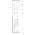
本実施形態では、図4に示すように、出力歯車5の肉抜き穴34を貫通して、薄肉に形成された中央部33に振動吸収材35が加硫接着により一体に接合されている。この振動吸収材35はNBR(アクリロニトリル-ブタジエンゴム)等の合成ゴムからなり、図4(a)に示すように、隣接する支持軸受20の外輪24の外径よりも外周側に接合されている。そして、振動吸収材35の側面が外径部31やボス部32の幅面と略面一になるように設定されている。これにより、振動吸収材35の成形が容易になると共に、所望の寸法精度を確保することができる。また、振動吸収材35が肉抜き穴34を貫通して中央部33の両側面に接合されているので、振動吸収材35の剥がれや脱落を防止して信頼性を高めることができると共に、軽量化を図りつつ、出力歯車5の噛合い時、歯面5aに発生する振動を減衰させて不快な歯打ち音等の異音の発生を抑制することができ、(b)に示すように、外輪24との接触を防止して出力歯車5の円滑な回転運動を確保することができる。なお、ここでいう「略面一」の略とは、例えば、設計の狙い値であって実質的に段差がない状態、すなわち、加工誤差等によって生じる段差は当然許容されるべきものである。
振動吸収材35の材質としては、前述したNBR以外に、例えば、耐熱性に優れたHNBR(水素化アクリロニトリル-ブタジエンゴム)、EPM、EPDM等をはじめ、耐熱性、耐薬品性に優れたACM(ポリアクリルゴム)、FKM(フッ素ゴム)等を例示することができる。
以上、本発明の実施の形態について説明を行ったが、本発明はこうした実施の形態に何等限定されるものではなく、あくまで例示であって、本発明の要旨を逸脱しない範囲内において、さらに種々なる形態で実施し得ることは勿論のことであり、本発明の範囲は、特許請求の範囲の記載によって示され、さらに特許請求の範囲に記載の均等の意味、および範囲内のすべての変更を含む。
本発明に係る歯車は、一般産業用の電動機、自動車等の駆動部に使用され、電動モータからの回転入力を、ボールねじ機構を介して駆動軸の直線運動に変換するボールねじ機構を備えた電動アクチュエータの出力歯車に適用できる。
1 電動アクチュエータ
2 ハウジング
2a 第1のハウジング
2b 第2のハウジング
3 入力歯車
3a モータ軸
4 中間歯車
5 出力歯車
5a 歯部
5b 円孔
6 減速機構
7 駆動軸
8 ボールねじ機構
9 止め輪
10 ねじ軸
10a、18a ねじ溝
11 貫通孔
12 袋孔
13、26 転がり軸受
14 キー
14a、32a キー溝
15 係止ピン
17 スリーブ
17a 凹溝
18 ナット
18b ナットの外周面
18c ナットの鍔部
19 ボール
20 支持軸受
20a シールド板
21 駒部材
22、30 ワッシャ
23 内輪
24、27 外輪
25 歯車軸
28 保持器
29 針状ころ
31 外径部
32 ボス部
33 中央部
34、34’ 肉抜き穴
35 振動吸収材
51 電動アクチュエータ
52 ハウジング
52a 第1のハウジング
52b 第2のハウジング
53 電動モータ
53a モータ軸
57 減速機構
59 駆動軸
58 ボールねじ機構
66 支持軸受
60 ねじ軸
61 ナット
60a、61a ねじ溝
62 ボール
63a 貫通孔
63b 袋孔
54 入力歯車
55 中間歯車
56 出力歯車
64 歯車軸
65 ブッシュ
67 内輪
61b ナットの外周面
68 外輪
56a ボス部
69 低騒音歯車
70 心部
71 歯部
72 金属歯車
73 振動吸収材
74a、74b 凹部
74c 連通部
M 電動モータ
2 ハウジング
2a 第1のハウジング
2b 第2のハウジング
3 入力歯車
3a モータ軸
4 中間歯車
5 出力歯車
5a 歯部
5b 円孔
6 減速機構
7 駆動軸
8 ボールねじ機構
9 止め輪
10 ねじ軸
10a、18a ねじ溝
11 貫通孔
12 袋孔
13、26 転がり軸受
14 キー
14a、32a キー溝
15 係止ピン
17 スリーブ
17a 凹溝
18 ナット
18b ナットの外周面
18c ナットの鍔部
19 ボール
20 支持軸受
20a シールド板
21 駒部材
22、30 ワッシャ
23 内輪
24、27 外輪
25 歯車軸
28 保持器
29 針状ころ
31 外径部
32 ボス部
33 中央部
34、34’ 肉抜き穴
35 振動吸収材
51 電動アクチュエータ
52 ハウジング
52a 第1のハウジング
52b 第2のハウジング
53 電動モータ
53a モータ軸
57 減速機構
59 駆動軸
58 ボールねじ機構
66 支持軸受
60 ねじ軸
61 ナット
60a、61a ねじ溝
62 ボール
63a 貫通孔
63b 袋孔
54 入力歯車
55 中間歯車
56 出力歯車
64 歯車軸
65 ブッシュ
67 内輪
61b ナットの外周面
68 外輪
56a ボス部
69 低騒音歯車
70 心部
71 歯部
72 金属歯車
73 振動吸収材
74a、74b 凹部
74c 連通部
M 電動モータ
Claims (6)
- 外周に歯部と内周に円孔が形成され、前記歯部の近傍の外径部と前記円孔の近傍のボス部との間の中央部が前記外径部やボス部の幅より薄肉に形成されると共に、当該中央部に肉抜き穴が周方向等配に形成され、これらの肉抜き穴を貫通して前記中央部の両側面に合成ゴムからなる振動吸収材が隣接する軸受の外径よりも外周側に一体に接合されていることを特徴とする歯車。
- 前記肉抜き穴が前記中央部の外周側に形成されている請求項1に記載の歯車。
- 前記肉抜き穴が径方向外方に向って幅寸法が拡大する矩形状または三角形状に形成されている請求項1に記載の歯車。
- 前記振動吸収材の側面が前記歯車の外径部やボス部の幅面と略面一になるように設定されている請求項1に記載の歯車。
- 前記歯車が焼結合金から形成されている請求項1に記載の歯車。
- ハウジングと、
このハウジングに取り付けられた電動モータと、
この電動モータの回転力を、モータ軸を介して伝達する減速機構と、
この減速機構を介して前記電動モータの回転運動を駆動軸の軸方向の直線運動に変換するボールねじ機構とを備え、
このボールねじ機構が、前記ハウジングに装着された支持軸受を介して回転可能に、かつ軸方向移動不可に支持され、外周に前記減速機構を構成する出力歯車が固定され、内周に螺旋状のねじ溝が形成されたナットと、
このナットに多数のボールを介して内挿され、外周に前記ナットのねじ溝に対応する螺旋状のねじ溝が形成されて前記ハウジングに対して回転不可に、かつ軸方向移動可能に支持されたねじ軸とで構成された電動アクチュエータにおいて、
前記出力歯車が前記支持軸受の内輪と前記ナットの鍔部とで挟持された状態で当該ナットの外周面に固定され、前記出力歯車が前記請求項1乃至5いずれかに記載の歯車で構成されていることを特徴とする電動アクチュエータ。
Priority Applications (3)
| Application Number | Priority Date | Filing Date | Title |
|---|---|---|---|
| EP15861802.5A EP3222884A4 (en) | 2014-11-21 | 2015-11-20 | Gear and electric actuator provided with same |
| CN201580063074.2A CN107002853A (zh) | 2014-11-21 | 2015-11-20 | 齿轮和设置有该齿轮的电动致动器 |
| US15/600,926 US20170252795A1 (en) | 2014-11-21 | 2017-05-22 | Gear And An Electric Actuator Provided Therewith |
Applications Claiming Priority (2)
| Application Number | Priority Date | Filing Date | Title |
|---|---|---|---|
| JP2014-236133 | 2014-11-21 | ||
| JP2014236133A JP2016098906A (ja) | 2014-11-21 | 2014-11-21 | 歯車およびこれを備えた電動アクチュエータ |
Related Child Applications (1)
| Application Number | Title | Priority Date | Filing Date |
|---|---|---|---|
| US15/600,926 Continuation US20170252795A1 (en) | 2014-11-21 | 2017-05-22 | Gear And An Electric Actuator Provided Therewith |
Publications (1)
| Publication Number | Publication Date |
|---|---|
| WO2016080513A1 true WO2016080513A1 (ja) | 2016-05-26 |
Family
ID=56014045
Family Applications (1)
| Application Number | Title | Priority Date | Filing Date |
|---|---|---|---|
| PCT/JP2015/082673 Ceased WO2016080513A1 (ja) | 2014-11-21 | 2015-11-20 | 歯車およびこれを備えた電動アクチュエータ |
Country Status (5)
| Country | Link |
|---|---|
| US (1) | US20170252795A1 (ja) |
| EP (1) | EP3222884A4 (ja) |
| JP (1) | JP2016098906A (ja) |
| CN (1) | CN107002853A (ja) |
| WO (1) | WO2016080513A1 (ja) |
Families Citing this family (12)
| Publication number | Priority date | Publication date | Assignee | Title |
|---|---|---|---|---|
| GB2547035B (en) * | 2016-02-05 | 2019-03-13 | Ford Global Tech Llc | Gear assembly |
| JP6678538B2 (ja) * | 2016-08-18 | 2020-04-08 | 株式会社日立ニコトランスミッション | 内歯車および遊星歯車装置 |
| JP6831207B2 (ja) | 2016-10-20 | 2021-02-17 | 三菱重工エンジン&ターボチャージャ株式会社 | ロッカーアーム |
| DE102018215381A1 (de) * | 2018-09-11 | 2019-06-27 | Zf Friedrichshafen Ag | Getriebe |
| DE102018123045A1 (de) * | 2018-09-19 | 2020-03-19 | Fte Automotive Gmbh | Elektrischer Kupplungsaktuator mit Getriebelagerplatte |
| JP7065753B2 (ja) * | 2018-11-21 | 2022-05-12 | 株式会社ミツバ | モータ装置およびその製造方法 |
| JP7156039B2 (ja) * | 2019-01-09 | 2022-10-19 | 株式会社デンソー | アクチュエータ |
| CN111022599B (zh) * | 2019-11-28 | 2021-06-08 | 北京自动化控制设备研究所 | 用于行星滚柱丝杠的支撑装置及具有其的机电作动器 |
| DE102020103729B3 (de) * | 2020-02-13 | 2021-07-29 | Nidec Corporation | Verfahren zur Herstellung einer Motorwelle eines Aktuators mit Verzahnung und Lagersitz, Aktuator, Automatikgetriebeeinheit und Hybridfahrzeug |
| CN113653785A (zh) * | 2021-08-27 | 2021-11-16 | 广西玉柴机器股份有限公司 | 一种发动机轻量化的减振降噪齿轮 |
| CN115446560B (zh) * | 2022-10-12 | 2023-08-22 | 重庆建设工业(集团)有限责任公司 | 一种大直径薄壁管传动轴的机加工方法 |
| JP2025018524A (ja) * | 2023-07-27 | 2025-02-06 | Nok株式会社 | ギヤ構造体 |
Citations (4)
| Publication number | Priority date | Publication date | Assignee | Title |
|---|---|---|---|---|
| JPS55161952U (ja) * | 1979-05-09 | 1980-11-20 | ||
| JPS56153659U (ja) * | 1980-04-17 | 1981-11-17 | ||
| JPH03110251U (ja) * | 1990-02-27 | 1991-11-12 | ||
| JP2013148108A (ja) * | 2012-01-17 | 2013-08-01 | Ntn Corp | 電動リニアアクチュエータ |
Family Cites Families (13)
| Publication number | Priority date | Publication date | Assignee | Title |
|---|---|---|---|---|
| US4170549A (en) * | 1975-12-08 | 1979-10-09 | Johnson Louis W | Vibrating screen apparatus |
| JPS56153659A (en) * | 1980-04-28 | 1981-11-27 | Mitsubishi Electric Corp | High-pressure electric discharge lamp |
| JPS5830066U (ja) * | 1981-08-21 | 1983-02-26 | ソニー株式会社 | 記録再生装置用歯車 |
| DE9313547U1 (de) * | 1993-09-08 | 1995-01-12 | Robert Bosch Gmbh, 70469 Stuttgart | Stirnradgetriebe, insbesondere für Stellantriebe von Sitzen in Kraftfahrzeugen |
| JP3160165B2 (ja) * | 1994-09-30 | 2001-04-23 | 富士機工株式会社 | 車両用ドライブプレート |
| CN201568548U (zh) * | 2009-07-06 | 2010-09-01 | 浙江吉利汽车研究院有限公司 | 一种减振降噪齿轮 |
| CN102374272B (zh) * | 2010-08-27 | 2014-02-19 | 鸿富锦精密工业(深圳)有限公司 | 磁齿轮 |
| JP5918510B2 (ja) * | 2011-11-16 | 2016-05-18 | Ntn株式会社 | 電動リニアアクチュエータ |
| CN202790403U (zh) * | 2012-07-19 | 2013-03-13 | 富莱茵汽车部件有限公司 | 凸轮轴正时齿轮 |
| JP6111042B2 (ja) * | 2012-10-30 | 2017-04-05 | Ntn株式会社 | 電動リニアアクチュエータ |
| JP6523631B2 (ja) * | 2014-08-12 | 2019-06-05 | Ntn株式会社 | 歯車およびこれを備えた電動アクチュエータ |
| US10100673B2 (en) * | 2015-09-04 | 2018-10-16 | Hamilton Sundstrand Corporation | Pump gear |
| JP6357181B2 (ja) * | 2016-03-11 | 2018-07-11 | ミネベアミツミ株式会社 | 駆動装置 |
-
2014
- 2014-11-21 JP JP2014236133A patent/JP2016098906A/ja active Pending
-
2015
- 2015-11-20 WO PCT/JP2015/082673 patent/WO2016080513A1/ja not_active Ceased
- 2015-11-20 CN CN201580063074.2A patent/CN107002853A/zh active Pending
- 2015-11-20 EP EP15861802.5A patent/EP3222884A4/en not_active Withdrawn
-
2017
- 2017-05-22 US US15/600,926 patent/US20170252795A1/en not_active Abandoned
Patent Citations (4)
| Publication number | Priority date | Publication date | Assignee | Title |
|---|---|---|---|---|
| JPS55161952U (ja) * | 1979-05-09 | 1980-11-20 | ||
| JPS56153659U (ja) * | 1980-04-17 | 1981-11-17 | ||
| JPH03110251U (ja) * | 1990-02-27 | 1991-11-12 | ||
| JP2013148108A (ja) * | 2012-01-17 | 2013-08-01 | Ntn Corp | 電動リニアアクチュエータ |
Non-Patent Citations (1)
| Title |
|---|
| See also references of EP3222884A4 * |
Also Published As
| Publication number | Publication date |
|---|---|
| US20170252795A1 (en) | 2017-09-07 |
| JP2016098906A (ja) | 2016-05-30 |
| EP3222884A4 (en) | 2018-06-27 |
| EP3222884A1 (en) | 2017-09-27 |
| CN107002853A (zh) | 2017-08-01 |
Similar Documents
| Publication | Publication Date | Title |
|---|---|---|
| WO2016080513A1 (ja) | 歯車およびこれを備えた電動アクチュエータ | |
| JP6091149B2 (ja) | 電動リニアアクチュエータ | |
| JP6111042B2 (ja) | 電動リニアアクチュエータ | |
| JP5918510B2 (ja) | 電動リニアアクチュエータ | |
| WO2016024578A1 (ja) | 歯車およびこれを備えた電動アクチュエータ | |
| JP5877763B2 (ja) | 電動リニアアクチュエータ | |
| JP2013104525A5 (ja) | ||
| JP6111043B2 (ja) | 電動リニアアクチュエータ | |
| JP5855547B2 (ja) | 電動リニアアクチュエータ | |
| JP6114548B2 (ja) | 電動リニアアクチュエータ | |
| JP2013148108A (ja) | 電動リニアアクチュエータ | |
| JP2016151332A (ja) | ボールねじおよびこれを備えた電動リニアアクチュエータ | |
| JP6039748B1 (ja) | 電動アクチュエータ | |
| WO2016052477A1 (ja) | 電動アクチュエータ | |
| JP5982220B2 (ja) | 電動リニアアクチュエータ | |
| JP6074192B2 (ja) | 電動リニアアクチュエータ | |
| JP6121760B2 (ja) | 電動リニアアクチュエータ | |
| JP6429534B2 (ja) | 電動アクチュエータ | |
| JP6111038B2 (ja) | 電動リニアアクチュエータ | |
| JP6130235B2 (ja) | 電動リニアアクチュエータ | |
| JP2015175382A (ja) | 電動アクチュエータ | |
| JP2015040595A (ja) | 電動アクチュエータ | |
| JP2016114118A (ja) | 電動アクチュエータ | |
| JP6239995B2 (ja) | 電動アクチュエータ |
Legal Events
| Date | Code | Title | Description |
|---|---|---|---|
| 121 | Ep: the epo has been informed by wipo that ep was designated in this application |
Ref document number: 15861802 Country of ref document: EP Kind code of ref document: A1 |
|
| NENP | Non-entry into the national phase |
Ref country code: DE |
|
| REEP | Request for entry into the european phase |
Ref document number: 2015861802 Country of ref document: EP |