WO2016080554A1 - 繊維強化樹脂ネジ - Google Patents
繊維強化樹脂ネジ Download PDFInfo
- Publication number
- WO2016080554A1 WO2016080554A1 PCT/JP2015/083300 JP2015083300W WO2016080554A1 WO 2016080554 A1 WO2016080554 A1 WO 2016080554A1 JP 2015083300 W JP2015083300 W JP 2015083300W WO 2016080554 A1 WO2016080554 A1 WO 2016080554A1
- Authority
- WO
- WIPO (PCT)
- Prior art keywords
- resin
- screw
- fiber
- fiber reinforced
- reinforced resin
- Prior art date
- Legal status (The legal status is an assumption and is not a legal conclusion. Google has not performed a legal analysis and makes no representation as to the accuracy of the status listed.)
- Ceased
Links
Images

Classifications
-
- F—MECHANICAL ENGINEERING; LIGHTING; HEATING; WEAPONS; BLASTING
- F16—ENGINEERING ELEMENTS AND UNITS; GENERAL MEASURES FOR PRODUCING AND MAINTAINING EFFECTIVE FUNCTIONING OF MACHINES OR INSTALLATIONS; THERMAL INSULATION IN GENERAL
- F16B—DEVICES FOR FASTENING OR SECURING CONSTRUCTIONAL ELEMENTS OR MACHINE PARTS TOGETHER, e.g. NAILS, BOLTS, CIRCLIPS, CLAMPS, CLIPS OR WEDGES; JOINTS OR JOINTING
- F16B33/00—Features common to bolt and nut
- F16B33/006—Non-metallic fasteners using screw-thread
-
- B—PERFORMING OPERATIONS; TRANSPORTING
- B29—WORKING OF PLASTICS; WORKING OF SUBSTANCES IN A PLASTIC STATE IN GENERAL
- B29C—SHAPING OR JOINING OF PLASTICS; SHAPING OF MATERIAL IN A PLASTIC STATE, NOT OTHERWISE PROVIDED FOR; AFTER-TREATMENT OF THE SHAPED PRODUCTS, e.g. REPAIRING
- B29C45/00—Injection moulding, i.e. forcing the required volume of moulding material through a nozzle into a closed mould; Apparatus therefor
- B29C45/0005—Injection moulding, i.e. forcing the required volume of moulding material through a nozzle into a closed mould; Apparatus therefor using fibre reinforcements
-
- F—MECHANICAL ENGINEERING; LIGHTING; HEATING; WEAPONS; BLASTING
- F16—ENGINEERING ELEMENTS AND UNITS; GENERAL MEASURES FOR PRODUCING AND MAINTAINING EFFECTIVE FUNCTIONING OF MACHINES OR INSTALLATIONS; THERMAL INSULATION IN GENERAL
- F16B—DEVICES FOR FASTENING OR SECURING CONSTRUCTIONAL ELEMENTS OR MACHINE PARTS TOGETHER, e.g. NAILS, BOLTS, CIRCLIPS, CLAMPS, CLIPS OR WEDGES; JOINTS OR JOINTING
- F16B33/00—Features common to bolt and nut
- F16B33/02—Shape of thread; Special thread-forms
-
- B—PERFORMING OPERATIONS; TRANSPORTING
- B29—WORKING OF PLASTICS; WORKING OF SUBSTANCES IN A PLASTIC STATE IN GENERAL
- B29C—SHAPING OR JOINING OF PLASTICS; SHAPING OF MATERIAL IN A PLASTIC STATE, NOT OTHERWISE PROVIDED FOR; AFTER-TREATMENT OF THE SHAPED PRODUCTS, e.g. REPAIRING
- B29C45/00—Injection moulding, i.e. forcing the required volume of moulding material through a nozzle into a closed mould; Apparatus therefor
- B29C45/0005—Injection moulding, i.e. forcing the required volume of moulding material through a nozzle into a closed mould; Apparatus therefor using fibre reinforcements
- B29C2045/0006—Injection moulding, i.e. forcing the required volume of moulding material through a nozzle into a closed mould; Apparatus therefor using fibre reinforcements the fibres being oriented in a direction perpendicular to the flow direction of the moulding material into the mould
-
- B—PERFORMING OPERATIONS; TRANSPORTING
- B29—WORKING OF PLASTICS; WORKING OF SUBSTANCES IN A PLASTIC STATE IN GENERAL
- B29D—PRODUCING PARTICULAR ARTICLES FROM PLASTICS OR FROM SUBSTANCES IN A PLASTIC STATE
- B29D1/00—Producing articles with screw-threads
- B29D1/005—Producing articles with screw-threads fibre reinforced
-
- B—PERFORMING OPERATIONS; TRANSPORTING
- B29—WORKING OF PLASTICS; WORKING OF SUBSTANCES IN A PLASTIC STATE IN GENERAL
- B29K—INDEXING SCHEME ASSOCIATED WITH SUBCLASSES B29B, B29C OR B29D, RELATING TO MOULDING MATERIALS OR TO MATERIALS FOR MOULDS, REINFORCEMENTS, FILLERS OR PREFORMED PARTS, e.g. INSERTS
- B29K2071/00—Use of polyethers, e.g. PEEK, i.e. polyether-etherketone or PEK, i.e. polyetherketone or derivatives thereof, as moulding material
-
- B—PERFORMING OPERATIONS; TRANSPORTING
- B29—WORKING OF PLASTICS; WORKING OF SUBSTANCES IN A PLASTIC STATE IN GENERAL
- B29K—INDEXING SCHEME ASSOCIATED WITH SUBCLASSES B29B, B29C OR B29D, RELATING TO MOULDING MATERIALS OR TO MATERIALS FOR MOULDS, REINFORCEMENTS, FILLERS OR PREFORMED PARTS, e.g. INSERTS
- B29K2105/00—Condition, form or state of moulded material or of the material to be shaped
- B29K2105/06—Condition, form or state of moulded material or of the material to be shaped containing reinforcements, fillers or inserts
- B29K2105/12—Condition, form or state of moulded material or of the material to be shaped containing reinforcements, fillers or inserts of short lengths, e.g. chopped filaments, staple fibres or bristles
- B29K2105/14—Condition, form or state of moulded material or of the material to be shaped containing reinforcements, fillers or inserts of short lengths, e.g. chopped filaments, staple fibres or bristles oriented
-
- B—PERFORMING OPERATIONS; TRANSPORTING
- B29—WORKING OF PLASTICS; WORKING OF SUBSTANCES IN A PLASTIC STATE IN GENERAL
- B29K—INDEXING SCHEME ASSOCIATED WITH SUBCLASSES B29B, B29C OR B29D, RELATING TO MOULDING MATERIALS OR TO MATERIALS FOR MOULDS, REINFORCEMENTS, FILLERS OR PREFORMED PARTS, e.g. INSERTS
- B29K2309/00—Use of inorganic materials not provided for in groups B29K2303/00 - B29K2307/00, as reinforcement
- B29K2309/08—Glass
-
- B—PERFORMING OPERATIONS; TRANSPORTING
- B29—WORKING OF PLASTICS; WORKING OF SUBSTANCES IN A PLASTIC STATE IN GENERAL
- B29L—INDEXING SCHEME ASSOCIATED WITH SUBCLASS B29C, RELATING TO PARTICULAR ARTICLES
- B29L2001/00—Articles provided with screw threads
- B29L2001/007—Screws
Definitions
- the present invention relates to a fiber reinforced resin screw using a resin composition containing a reinforced fiber in a resin as a material.
- Resin screws have various characteristics, but their application range is limited because they have lower strength than metal screws. Therefore, it could not be used in fields where higher strength is required.
- Patent Document 1 discloses a resin screw mixed with fibers to improve the tensile fracture strength of the screw.
- long fibers having an average fiber length of 0.3 mm or more are mixed into the thermoplastic resin to increase the bonding force / adhesion force between the reinforcing fiber and the resin, and as a composite material The strength is improved.
- the fiber-reinforced resin bolt described in Patent Document 1 improves the tensile fracture strength of the bolt by strongly orienting long fibers having an average fiber length of 0.3 mm or more parallel to the axial direction of the screw. Yes.
- the screwed length between the male screw and the female screw is shortened as in the case where screw coupling is desired in a smaller space. If you want to do so, the thread strength may be insufficient.
- An object of the present invention is to improve the strength of a thread in a fiber-reinforced resin screw.
- the fiber reinforced resin screw according to the present invention is a screw formed using a resin composition containing a reinforced fiber in a resin.
- the thread pitch in the fiber reinforced resin screw is 1.5 to 2 times the standard pitch corresponding to the outer diameter of the thread specified in the standard of metric coarse screw, unified coarse screw or unified fine screw. Length.
- the average fiber length of the reinforcing fibers is 1 to 1/3 times the thread pitch of the fiber-reinforced resin screw.
- the content of reinforcing fibers in the resin composition is 20 to 80%.
- the fiber reinforced resin screw according to the present invention is a screw formed using a resin composition containing a reinforced fiber in a resin.
- the pitch of the thread in the fiber reinforced resin screw is 1/4 to 1-2.2 of the screw outer diameter.
- the average fiber length of the reinforcing fibers is 1 to 1/3 times the pitch.
- the content of reinforcing fibers in the resin composition is 20 to 80%.
- the angle of the thread in the fiber reinforced resin screw is 60 to 90 °.
- the outer diameter of the fiber reinforced resin screw is 3.5 to 10 mm.
- Resins in the resin composition are aromatic polyetherketone resin, polyamide resin, polyimide resin, polyphenylene sulfide resin, polyvinylidene fluoride resin, polycarbonate resin, polyacetal resin, phenol resin, ultrahigh molecular weight polyethylene resin, tetrafluoroethylene par Fluoroalkyl vinyl ether resin, polybutylene terephthalate resin, or polyvinyl chloride resin.
- the reinforcing fiber in the resin composition is glass fiber, carbon fiber, silicon carbide fiber, aramid fiber, or ultrahigh molecular weight polyethylene fiber.
- a resin screw having a high thread strength can be provided.
- a resin screw having a high thread strength can be provided.
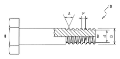
- FIG. 1 is a partial cross-sectional view of a fiber reinforced resin screw (male screw) according to the present invention.
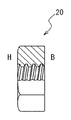
- FIG. 2 is a partial cross-sectional view of a fiber reinforced resin screw (female screw) according to the present invention.
- (A) of FIG. 3 is a figure showing the orientation analysis result of the reinforcing fiber in the male screw having a thread angle A (60 °) equivalent to UNF3 / 16 and a pitch P (32 threads / inch).
- FIG. (A) of FIG. 4 is a figure showing the orientation analysis result of the reinforcing fiber in the male screw having a thread angle A (60 °) equivalent to UNF3 / 16 and a pitch P (32 threads / inch).
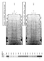
- FIG. (A) of FIG. 5 is a figure showing the orientation analysis result of the reinforcing fiber in the external thread having a thread angle A (60 °) equivalent to UNF3 / 16 and a pitch P (32 threads / inch).
- FIG. 5B is a diagram showing the orientation analysis result of the reinforcing fiber in the male screw in which the thread pitch P is changed to 1.2 times that of UNF3 / 16.
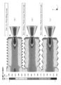
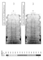
- FIG. 6A is a view showing the orientation analysis result of the reinforcing fiber in the male screw in which the thread pitch P is changed to 1.4 times that of UNF3 / 16, and FIG. These are the figures showing the orientation analysis result of the reinforcing fiber in the external thread which changed the thread pitch P to 1.6 times with respect to UNF3 / 16.
- FIG. 7A is a diagram showing the orientation analysis result of the reinforcing fiber in the male screw in which the thread pitch P is changed to 1.8 times that of UNF3 / 16, and FIG. These are the figures showing the orientation analysis result of the reinforced fiber in the external thread which changed the pitch P of the thread to 2 times with respect to UNF3 / 16.
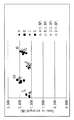
- FIG. 8 is a diagram illustrating a change in tensile strength (kN) of the fiber-reinforced resin screw when the content ratio of the resin and the reinforcing fiber is changed.
- FIG. 1 is a partial cross-sectional view showing a partial cross section of a fiber-reinforced resin screw (male screw) according to the first embodiment.
- FIG. 2 is a partial cross-sectional view showing a partial cross section of the fiber reinforced resin screw (female screw) according to the first embodiment. Note that the thread shape of the female screw shown in FIG. 2 is the same as that of the male screw shown in FIG.
- the fiber reinforced resin screws 10 and 20 which concern on 1st Embodiment are the screws shape
- molded using the resin composition in which the reinforced fiber was contained in resin, 3.5 mm ⁇
- the outer diameter D is in the range of 10 mm.
- a screw having a large outer diameter D has a large screw thread, and the width of the bottom of the screw thread becomes long, so that the thread has high strength.
- the strength of the thread may be insufficient.
- the pitch P in the fiber reinforced resin screw is set to be longer than the pitch of a standard screw that is generally used, it is possible to lengthen the skirt of the thread and improve the strength of the thread.
- the pitch P of the fiber reinforced resin screws 10 and 20 is preferably D / 4.3 to D / 2.2 with respect to the outer diameter D of the screw.
- the pitch P of the resin screws 10 and 20 is 1.5 to 2 times the standard pitch corresponding to the outer diameter of the thread specified in the standard of metric coarse screw, unified coarse screw or unified fine screw. It is preferable to use a length.
- a gate is generally arranged at the screw head H or the screw bottom B, and at this time, most of the resin composition is orthogonal to the screw thread. Flowing. Therefore, the flow of the resin composition tends to be directed in the axial direction even at the thread portion.
- the skirt of the thread is secured long, the entrance width of the resin can be increased with respect to the height of the thread, so that the resin fluidity along the shape of the thread can be obtained.
- the reinforcing fibers contained in the resin composition are oriented along the unevenness of the thread or the surface forming the screw. Increases the strength against shearing of mountains. In this way, a resin screw having high thread strength can be obtained.
- the pitch P of the fiber reinforced resin screws 10 and 20 is increased, and the top of the screw thread (top land) or the bottom of the screw (bottom land) is formed in parallel to the axis of the screw.
- this parallel portion By setting this parallel portion to be long in the axial direction, it is possible to ensure a long thread skirt. And the resin fluidity
- this parallel part is made too long, when the fiber reinforced resin screws 10 and 20 are screwed together, the screwing length (the length at which the male screw and the female screw are screwed) becomes too long. .
- the pitch P of the fiber reinforced resin screws 10 and 20 is desirably in a range of 1.5 to 2 times the standard pitch of the metric coarse screw, the unified coarse screw, or the unified fine screw.
- the coefficient of friction ⁇ between the threads of the fiber reinforced resin screws 10 and 20 is about 0.1, the lead angle of the threads can be laid until the pitch is about 1.8 times that of the standard screw. it can.
- the average fiber length of the reinforcing fibers contained in the fiber reinforced resin screws 10 and 20 is preferably 1 to 1/3 times the pitch P, or the height of the thread.
- the average fiber length is short, the effect of improving the tensile strength in the axial direction of the screw and improving the strength of the thread due to the inclusion of the reinforcing fiber is hindered.
- the average fiber length is too long, the flow of the reinforcing fiber at the time of injection molding becomes difficult to follow the unevenness of the thread or the surface forming the thread, and the strength of the thread is not improved.
- the thread angle A is 60 °.
- the screw thread angle A of the fiber reinforced resin screws 10 and 20 is larger than the screw thread angle A of a general standard screw, the inclination in the axial direction of the screw thread becomes gentle, and the reinforcing fiber is screw thread. It becomes easy to flow along the unevenness
- the upper limit of the thread angle A is considered to be about 105 ° from the self-standing condition of the screw. Practically, the thread angle A is preferably about 60 to 90 °.
- the shape of the thread of the fiber reinforced resin screws 10 and 20 is a trapezoidal screw.
- the present invention is not limited to trapezoidal screws, and the bottoms of the screws can be U-shaped valleys. Further, it is preferable to increase the valley diameter d and secure a long skirt portion of the screw thread, but it is not preferable to make the valley diameter d too large because the hook height between the screw threads decreases.
- the raw material resin constituting the fiber reinforced resin screws 10 and 20 is aromatic polyetherketone resin (PEEK, PEK, etc.), polyamide resin, polyimide resin, polyphenylene sulfide, depending on the use of the fiber reinforced resin screws 10 and 20.
- the reinforcing fiber glass fiber, carbon fiber, silicon carbide fiber, aramid fiber, ultrahigh molecular weight polyethylene fiber, and other reinforcing fibers can be used.
- the amount of the reinforcing fibers contained in the fiber reinforced resin screws 10 and 20 is preferably 20 to 80%, more preferably 30 to 60%.
- non-conductive reinforcing fibers such as glass fibers for applications that require explosion-proof properties and electrolytic corrosion properties.
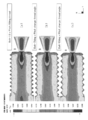
- FIGS. 3 to 7 represent the probability that the fiber is oriented in the axial direction (Y direction) of the screw, and when the value is 9 ⁇ 10 ⁇ 1. This shows that 90% of the reinforcing fibers in the part are oriented in the axial direction (Y direction).
- the gate for injecting the resin composition containing the reinforcing fiber is arranged at the bottom B of the screw.
- the tensile strength of the fiber reinforced resin screws 10 and 20 is improved by allowing the resin composition to flow in the axial direction of the screw.
- the average fiber length of the reinforcing fibers contained in the fiber reinforced resin screws 10 and 20 is 1 to 1/3 times the pitch P.
- FIG. 3 shows the orientation analysis result of the reinforcing fiber when the male screw having the thread angle A (60 °) equivalent to UNF3 / 16 and the pitch P (32 threads / inch) is injection-molded.
- FIG. 4A shows the orientation analysis results of the reinforcing fibers when male threads having a thread angle A (60 °) equivalent to UNF3 / 16 and a pitch P (32 threads / inch) are injection-molded.
- FIG. 4A shows the orientation analysis results of the reinforcing fibers when male threads having a thread angle A (60 °) equivalent to UNF3 / 16 and a pitch P (32 threads / inch) are injection-molded.
- FIG. 4B shows the result of orientation analysis of the reinforcing
- the boundary of the color enters the uneven shape of the thread as the thread angle A increases, and the flow of the reinforcing fiber contained in the resin composition is It can be seen that the tendency to be oriented along the uneven shape is stronger. Therefore, it can be determined that the thread strength is improved.
- FIG. 5 shows the orientation analysis result of the reinforcing fiber at the time of injection molding a male screw having a thread angle A (60 °) equivalent to UNF3 / 16 and a pitch P (32 threads / inch).
- FIG. (B) of FIG. 5 is a diagram showing the orientation analysis result of the reinforcing fiber when the external thread in which the thread pitch P is changed to 1.2 times that of UNF3 / 16 is injection-molded.
- FIG. 6 (a) is a diagram showing the orientation analysis result of the reinforcing fiber when injection molding a male screw in which the thread pitch P is changed to 1.4 times that of UNF3 / 16.
- FIG. 6B is a view showing the orientation analysis result of the reinforcing fiber when the male screw in which the thread pitch P is changed to 1.6 times that of UNF3 / 16 is injection-molded.
- FIG. 7 is a figure showing the orientation analysis result of the reinforcing fiber at the time of injection-molding a male screw in which the thread pitch P is changed to 1.8 times that of UNF3 / 16.
- B is a figure showing the orientation analysis result of the reinforcing fiber when injection molding a male screw in which the thread pitch P is changed to twice that of UNF3 / 16.
- FIGS. 5 to 7 As shown in FIGS. 5 to 7, as the thread pitch P increases, the thread skirt becomes longer, and the flow of the reinforcing fibers contained in the resin composition follows the uneven shape of the thread. It can be seen that the tendency to be oriented has increased. Therefore, it can be determined that the thread strength is improved.
- the vertical axis in FIG. 8 is the tensile strength (kN).
- the symbol A of the material represents a resin composition in which high-viscosity PEEK (polyether ether ketone) is used as a resin and 30% glass fiber is contained as a reinforcing fiber.
- the symbol B of the material represents a resin composition in which low-viscosity PEEK is used as a resin and 60% glass fiber is contained as a reinforcing fiber.
- the symbol C of the material represents a resin composition in which medium-viscosity PEEK is used for the resin and 30% glass fiber is contained as a reinforcing fiber.
- the symbol D of the material represents a resin composition in which low-viscosity PEEK is used for the resin and 50% glass fiber is contained as a reinforcing fiber.
- the measurement results of symbols A, B, C, and D show the tensile strength of fiber reinforced resin screws 10 and 20 having a thread angle A (60 °) equivalent to UNF3 / 16 and a pitch P (32 threads / inch). It is a test result.
- the symbols A (1.5P), B (1.5P), C (1.5P), and D (1.5P) are the thread angle A (60 °) equivalent to UNF3 / 16, And tensile strength test results for fiber reinforced resin screws 10 and 20 having a pitch P (21 threads / inch).
- the average fiber length of the reinforcing fibers contained in the fiber reinforced resin screws 10 and 20 is set to 1 to 1/3 times the pitch P, and the thread pitch P is increased. It can be seen that the average tensile strength is improved (about 4 to 10%).
Landscapes
- Engineering & Computer Science (AREA)
- General Engineering & Computer Science (AREA)
- Mechanical Engineering (AREA)
- Manufacturing & Machinery (AREA)
- Compositions Of Macromolecular Compounds (AREA)
- Reinforced Plastic Materials (AREA)
- Moulding By Coating Moulds (AREA)
Abstract
Description
て、ガラス繊維、炭素繊維、炭化珪素繊維、アラミド繊維、超高分子量ポリエチレン繊維、その他の強化繊維を用いることができる。繊維強化樹脂ネジ10、20に含有する強化繊維の量は、20乃至80%の含有率とすることが好ましく、30~60%とすることが、より好ましい。特に、防爆性や電食性が要求される用途には、ガラス繊維などの非導電性を備える強化繊維を用いることが望ましい。
Claims (10)
- 樹脂に強化繊維を含有させた樹脂組成物を用いて成形した繊維強化樹脂ネジであって、
前記繊維強化樹脂ネジにおけるネジ山のピッチは、メートル並目ネジ、ユニファイ並目ネジ又はユニファイ細目ネジの規格に規定される前記ネジ山の外径に対応する規格ピッチの1.5乃至2倍の長さであり、
前記強化繊維の平均繊維長さは、前記繊維強化樹脂ネジにおけるネジ山のピッチの1乃至1/3倍であり、
前記強化繊維の含有率は、20乃至80%である
繊維強化樹脂ネジ。 - 請求項1に記載の繊維強化樹脂ネジにおいて、
前記繊維強化樹脂ネジにおけるネジ山の角度は、60乃至90°である
繊維強化樹脂ネジ。 - 請求項1又は2に記載の繊維強化樹脂ネジにおいて、
前記繊維強化樹脂ネジの外径は、3.5乃至10mmである
繊維強化樹脂ネジ。 - 請求項1乃至3のいずれか一項に記載の繊維強化樹脂ネジにおいて、
前記樹脂は、芳香族ポリエーテルケトン樹脂、ポリアミド樹脂、ポリイミド樹脂、ポリフェニレンサルファイド樹脂、ポリふっ化ビニリデン樹脂、ポリカーボネード樹脂、ポリアセタール樹脂、フェノール樹脂、超高分子量ポリエチレン樹脂、テトラフルオロエチレン・パーフルオロアルキルビニルエーテル樹脂、ポリブチレンテレフタレート樹脂、又はポリ塩化ビニル樹脂である
繊維強化樹脂ネジ。 - 請求項1乃至4のいずれか一項に記載の繊維強化樹脂ネジにおいて、
前記強化繊維は、ガラス繊維、炭素繊維、炭化珪素繊維、アラミド繊維、又は超高分子量ポリエチレン繊維である
繊維強化樹脂ネジ。 - 樹脂に強化繊維を含有させた樹脂組成物を用いて成形した繊維強化樹脂ネジであって、
前記繊維強化樹脂ネジにおけるネジ山のピッチは、ネジ外径の1/4.3乃至1/2.2倍の長さであり、
前記強化繊維の平均繊維長さは、前記ピッチの1乃至1/3倍であり、
前記強化繊維の含有率は、20乃至80%である
繊維強化樹脂ネジ。 - 請求項6に記載の繊維強化樹脂ネジにおいて、
前記繊維強化樹脂ネジにおけるネジ山の角度は、60乃至90°である
繊維強化樹脂ネジ。 - 請求項6又は7に記載の繊維強化樹脂ネジにおいて、
前記繊維強化樹脂ネジの外径は、3.5乃至10mmである
繊維強化樹脂ネジ。 - 請求項6乃至8のいずれか一項に記載の繊維強化樹脂ネジにおいて、
前記樹脂は、芳香族ポリエーテルケトン樹脂、ポリアミド樹脂、ポリイミド樹脂、ポリフェニレンサルファイド樹脂、ポリふっ化ビニリデン樹脂、ポリカーボネード樹脂、ポリアセタール樹脂、フェノール樹脂、超高分子量ポリエチレン樹脂、テトラフルオロエチレン・パーフルオロアルキルビニルエーテル樹脂、ポリブチレンテレフタレート樹脂、又はポリ塩化ビニル樹脂である
繊維強化樹脂ネジ。 - 請求項6乃至9のいずれか一項に記載の繊維強化樹脂ネジにおいて、
前記強化繊維は、ガラス繊維、炭素繊維、炭化珪素繊維、アラミド繊維、又は超高分子量ポリエチレン繊維である
繊維強化樹脂ネジ。
Priority Applications (5)
| Application Number | Priority Date | Filing Date | Title |
|---|---|---|---|
| US15/519,706 US10533596B2 (en) | 2014-11-21 | 2015-11-19 | Fiber reinforced resin screw |
| CA2965606A CA2965606C (en) | 2014-11-21 | 2015-11-19 | Fiber reinforced resin screw |
| EP15862015.3A EP3199825B1 (en) | 2014-11-21 | 2015-11-19 | Fiber-reinforced resin screw |
| BR112017007250-5A BR112017007250A2 (ja) | 2014-11-21 | 2015-11-19 | Textiles strengthening resin screw |
| CN201580056548.0A CN107208683B (zh) | 2014-11-21 | 2015-11-19 | 纤维强化树脂螺栓 |
Applications Claiming Priority (2)
| Application Number | Priority Date | Filing Date | Title |
|---|---|---|---|
| JP2014-236516 | 2014-11-21 | ||
| JP2014236516A JP6584066B2 (ja) | 2014-11-21 | 2014-11-21 | 繊維強化樹脂ネジ |
Publications (1)
| Publication Number | Publication Date |
|---|---|
| WO2016080554A1 true WO2016080554A1 (ja) | 2016-05-26 |
Family
ID=56014081
Family Applications (1)
| Application Number | Title | Priority Date | Filing Date |
|---|---|---|---|
| PCT/JP2015/083300 Ceased WO2016080554A1 (ja) | 2014-11-21 | 2015-11-19 | 繊維強化樹脂ネジ |
Country Status (7)
| Country | Link |
|---|---|
| US (1) | US10533596B2 (ja) |
| EP (1) | EP3199825B1 (ja) |
| JP (1) | JP6584066B2 (ja) |
| CN (1) | CN107208683B (ja) |
| BR (1) | BR112017007250A2 (ja) |
| CA (1) | CA2965606C (ja) |
| WO (1) | WO2016080554A1 (ja) |
Cited By (1)
| Publication number | Priority date | Publication date | Assignee | Title |
|---|---|---|---|---|
| JP2018008482A (ja) * | 2016-07-15 | 2018-01-18 | 日本ケミカルスクリュー株式会社 | ボルトの成形方法及びボルト、並びにボルト成形用金型 |
Families Citing this family (12)
| Publication number | Priority date | Publication date | Assignee | Title |
|---|---|---|---|---|
| EP3427921B1 (en) | 2017-07-14 | 2021-11-17 | Crompton Technology Group Limited | Composite ball screw |
| DE202018100151U1 (de) * | 2018-01-12 | 2018-02-21 | Ctg Carbon Team Germany Gmbh | Carbonfaserschraube |
| JP7049887B2 (ja) * | 2018-03-29 | 2022-04-07 | 三菱重工機械システム株式会社 | 液体充填バルブおよび充填機 |
| CN108729565A (zh) * | 2018-07-02 | 2018-11-02 | 沈阳建筑大学 | 一种断热桥螺纹连接件及断热桥方法 |
| JP7362109B2 (ja) * | 2019-06-17 | 2023-10-17 | 株式会社呉英製作所 | 止水ボルト部材、足場つなぎアンカー用化粧キャップ部材及び足場つなぎアンカー用化粧キャップ部材の組み付け方法 |
| CN110259796A (zh) * | 2019-07-11 | 2019-09-20 | 海盐精工标准件厂 | 一种螺栓 |
| EP3800036A1 (en) * | 2019-10-04 | 2021-04-07 | Crompton Technology Group Limited | Composite component with means to visually detect barely visible impact damage |
| EP3800035A1 (en) | 2019-10-04 | 2021-04-07 | Crompton Technology Group Limited | Composite component with means to visually detect barely visible impact damage |
| JP7555226B2 (ja) * | 2019-10-07 | 2024-09-24 | Ntn株式会社 | 樹脂ナット |
| KR102232209B1 (ko) * | 2019-12-13 | 2021-03-24 | 이성권 | 산업시설의 폐유체 처리를 위한 설비에 적용되는 내식 볼트 및 너트 |
| JP7007543B2 (ja) * | 2020-08-31 | 2022-01-24 | 株式会社NejiLaw | 雄体 |
| DE102024116060B3 (de) * | 2024-06-10 | 2025-06-05 | Bayerische Motoren Werke Aktiengesellschaft | Befestigungsanordnung einer Beleuchtungseinrichtung an einem Bauelement eines Fahrzeugs sowie Fahrzeug |
Citations (4)
| Publication number | Priority date | Publication date | Assignee | Title |
|---|---|---|---|---|
| JPH01310941A (ja) * | 1988-06-09 | 1989-12-15 | Osaka Gas Co Ltd | 強化プラスチック棒、その製造方法及び製造装置、強化プラスチックねじ、その製造方法及び製造装置 |
| JP2003056536A (ja) * | 2001-08-08 | 2003-02-26 | Sanko Techno Co Ltd | 繊維強化合成樹脂製ボルト及びナット |
| WO2013130184A2 (en) * | 2012-01-17 | 2013-09-06 | Greene, Tweed Of Delaware, Inc. | Molded composite threads |
| JP2014111980A (ja) * | 2012-11-12 | 2014-06-19 | Kitagawa Kogyo Co Ltd | ネジ |
Family Cites Families (16)
| Publication number | Priority date | Publication date | Assignee | Title |
|---|---|---|---|---|
| US2949054A (en) * | 1954-07-19 | 1960-08-16 | Glastic Corp | Threaded shaft of glass fiber reinforced plastic |
| AU5768573A (en) * | 1973-07-04 | 1975-01-09 | Screw-threaded members | |
| JPS60201932A (ja) * | 1984-03-26 | 1985-10-12 | Sekisui Chem Co Ltd | 繊維強化プラスチツクねじ状成形体およびその製造方法 |
| US4909690A (en) * | 1987-12-16 | 1990-03-20 | Textron Inc. | Composite fastener |
| US5057257A (en) * | 1990-02-20 | 1991-10-15 | Quantum Composites, Inc. | Method of transfer molding fiber-reinforced resin bolt products |
| US5234765A (en) * | 1991-02-08 | 1993-08-10 | Taylor Scott R | High torque and tensile strength threaded end for thermoplastic composite rod |
| DE4209265A1 (de) * | 1991-12-21 | 1993-06-24 | Dyckerhoff & Widmann Ag | Vorrichtung zur verankerung eines stabfoermigen zugglieds aus faserverbundwerkstoff |
| JPH07293535A (ja) | 1994-04-21 | 1995-11-07 | Polyplastics Co | 樹脂製ボルト及びその成形方法 |
| JPH07293534A (ja) * | 1994-04-21 | 1995-11-07 | Polyplastics Co | 樹脂製ボルト及びその成形方法 |
| DE4415195C2 (de) | 1994-04-30 | 1996-09-19 | Hoechst Ag | Langfaserverstärkte Schrauben und Gewindestäbe aus thermoplastischen Kunststoffen, diese Schrauben und Gewindestäbe und Verfahren zu deren Herstellung |
| JP3381535B2 (ja) * | 1996-11-07 | 2003-03-04 | チッソ株式会社 | 長短繊維強化ポリオレフィン複合構造物及びそれからなる成形体 |
| JP3901299B2 (ja) * | 1997-10-02 | 2007-04-04 | 双和化成株式会社 | Uボルトの製法 |
| DE102004021484B4 (de) * | 2004-04-30 | 2018-11-29 | Böllhoff Verbindungstechnik GmbH | Verfahren zum Herstellen einer Verbindungsanordnung |
| US8465241B2 (en) * | 2007-10-31 | 2013-06-18 | The Boeing Company | Composite fasteners containing multiple reinforcing fiber types |
| KR20100130286A (ko) * | 2009-06-03 | 2010-12-13 | 에스케이케미칼주식회사 | 섬유강화수지 볼트 및 그 제조방법 |
| US8758387B2 (en) * | 2011-07-15 | 2014-06-24 | University Of Iowa Research Foundation | Biofeedback training of anal and rectal muscles |
-
2014
- 2014-11-21 JP JP2014236516A patent/JP6584066B2/ja active Active
-
2015
- 2015-11-19 US US15/519,706 patent/US10533596B2/en active Active
- 2015-11-19 CN CN201580056548.0A patent/CN107208683B/zh not_active Expired - Fee Related
- 2015-11-19 CA CA2965606A patent/CA2965606C/en active Active
- 2015-11-19 BR BR112017007250-5A patent/BR112017007250A2/ja not_active IP Right Cessation
- 2015-11-19 EP EP15862015.3A patent/EP3199825B1/en active Active
- 2015-11-19 WO PCT/JP2015/083300 patent/WO2016080554A1/ja not_active Ceased
Patent Citations (4)
| Publication number | Priority date | Publication date | Assignee | Title |
|---|---|---|---|---|
| JPH01310941A (ja) * | 1988-06-09 | 1989-12-15 | Osaka Gas Co Ltd | 強化プラスチック棒、その製造方法及び製造装置、強化プラスチックねじ、その製造方法及び製造装置 |
| JP2003056536A (ja) * | 2001-08-08 | 2003-02-26 | Sanko Techno Co Ltd | 繊維強化合成樹脂製ボルト及びナット |
| WO2013130184A2 (en) * | 2012-01-17 | 2013-09-06 | Greene, Tweed Of Delaware, Inc. | Molded composite threads |
| JP2014111980A (ja) * | 2012-11-12 | 2014-06-19 | Kitagawa Kogyo Co Ltd | ネジ |
Cited By (1)
| Publication number | Priority date | Publication date | Assignee | Title |
|---|---|---|---|---|
| JP2018008482A (ja) * | 2016-07-15 | 2018-01-18 | 日本ケミカルスクリュー株式会社 | ボルトの成形方法及びボルト、並びにボルト成形用金型 |
Also Published As
| Publication number | Publication date |
|---|---|
| EP3199825B1 (en) | 2019-01-02 |
| JP6584066B2 (ja) | 2019-10-02 |
| EP3199825A4 (en) | 2017-11-29 |
| CN107208683A (zh) | 2017-09-26 |
| JP2016098910A (ja) | 2016-05-30 |
| CA2965606C (en) | 2018-10-23 |
| US10533596B2 (en) | 2020-01-14 |
| CN107208683B (zh) | 2020-04-07 |
| EP3199825A1 (en) | 2017-08-02 |
| CA2965606A1 (en) | 2016-05-26 |
| BR112017007250A2 (ja) | 2018-01-16 |
| US20170241465A1 (en) | 2017-08-24 |
Similar Documents
| Publication | Publication Date | Title |
|---|---|---|
| JP6584066B2 (ja) | 繊維強化樹脂ネジ | |
| EP3608091A1 (en) | Composite connector and method of manufacturing the same | |
| BR112017005619A2 (pt) | material compósito curável, e, métodos para fabricar uma estrutura de compósito e para fabricar um material compósito. | |
| JP2013510013A5 (ja) | ||
| US20250102095A1 (en) | Composite connectors and methods of manufacturing the same | |
| US9422774B2 (en) | Casing centralizer | |
| JP2016531026A5 (ja) | ||
| CN106459438B (zh) | 长纤维增强塑料复合材料及长纤维增强塑料复合材料的制备方法 | |
| US20200049182A1 (en) | Composite connectors and methods of manufacturing the same | |
| KR20210097172A (ko) | 압축 성형된 섬유 복합물 부품 및 제조 방법 | |
| JP2017119432A (ja) | 繊維強化プラスチックの製造方法および繊維強化プラスチック | |
| CN105570657A (zh) | 增强型玻璃钢拉挤型材 | |
| CN206816647U (zh) | Smc复合材料电缆槽安装螺丝 | |
| EP2960567B1 (en) | Reinforcement structure for structural body having fastening sections | |
| JP6754273B2 (ja) | 連続繊維補強材 | |
| CN203223660U (zh) | Ptfe分散级糊膏挤出管 | |
| CN108707316A (zh) | 一种新型玻璃钢材料 | |
| JP6735307B2 (ja) | ブレード | |
| CN205669670U (zh) | 新型玻璃钢 | |
| CN104154346B (zh) | 钢带增强波纹管 | |
| RU2021103561A (ru) | Подложка из полимерного сплава, армированная волокнами, и формованное изделие с ее использованием | |
| Hoang et al. | Effect of fibers and stacking sequence on mode Ⅱ fracture toughness of glass fiber reinforced unsaturated polyester resin composites | |
| TH160911A (th) | วัสดุขึ้นรูปคอมโพสิต, วัตถุขึ้นรูปแบบฉีด, และ วิธีการสำหรับการผลิตวัสดุขึ้นรูปคอมโพสิต | |
| TH70553B (th) | วัสดุขึ้นรูปคอมโพสิต, วัตถุขึ้นรูปแบบฉีด, และ วิธีการสำหรับการผลิตวัสดุขึ้นรูปคอมโพสิต | |
| KR20170081990A (ko) | 회색의 열전도성 수지 조성물 및 이를 이용한 방열 부품 |
Legal Events
| Date | Code | Title | Description |
|---|---|---|---|
| 121 | Ep: the epo has been informed by wipo that ep was designated in this application |
Ref document number: 15862015 Country of ref document: EP Kind code of ref document: A1 |
|
| WWE | Wipo information: entry into national phase |
Ref document number: 15519706 Country of ref document: US |
|
| REG | Reference to national code |
Ref country code: BR Ref legal event code: B01A Ref document number: 112017007250 Country of ref document: BR |
|
| ENP | Entry into the national phase |
Ref document number: 2965606 Country of ref document: CA |
|
| REEP | Request for entry into the european phase |
Ref document number: 2015862015 Country of ref document: EP |
|
| NENP | Non-entry into the national phase |
Ref country code: DE |
|
| ENP | Entry into the national phase |
Ref document number: 112017007250 Country of ref document: BR Kind code of ref document: A2 Effective date: 20170407 |