WO2016084298A1 - 継目無鋼管製造用装置列およびそれを利用した二相ステンレス継目無鋼管の製造方法 - Google Patents
継目無鋼管製造用装置列およびそれを利用した二相ステンレス継目無鋼管の製造方法 Download PDFInfo
- Publication number
- WO2016084298A1 WO2016084298A1 PCT/JP2015/005095 JP2015005095W WO2016084298A1 WO 2016084298 A1 WO2016084298 A1 WO 2016084298A1 JP 2015005095 W JP2015005095 W JP 2015005095W WO 2016084298 A1 WO2016084298 A1 WO 2016084298A1
- Authority
- WO
- WIPO (PCT)
- Prior art keywords
- cooling
- less
- steel pipe
- temperature
- heating
- Prior art date
- Legal status (The legal status is an assumption and is not a legal conclusion. Google has not performed a legal analysis and makes no representation as to the accuracy of the status listed.)
- Ceased
Links
Images

Classifications
-
- C—CHEMISTRY; METALLURGY
- C21—METALLURGY OF IRON
- C21D—MODIFYING THE PHYSICAL STRUCTURE OF FERROUS METALS; GENERAL DEVICES FOR HEAT TREATMENT OF FERROUS OR NON-FERROUS METALS OR ALLOYS; MAKING METAL MALLEABLE, e.g. BY DECARBURISATION OR TEMPERING
- C21D9/00—Heat treatment, e.g. annealing, hardening, quenching or tempering, adapted for particular articles; Furnaces therefor
- C21D9/08—Heat treatment, e.g. annealing, hardening, quenching or tempering, adapted for particular articles; Furnaces therefor for tubular bodies or pipes
- C21D9/085—Cooling or quenching
-
- B—PERFORMING OPERATIONS; TRANSPORTING
- B21—MECHANICAL METAL-WORKING WITHOUT ESSENTIALLY REMOVING MATERIAL; PUNCHING METAL
- B21B—ROLLING OF METAL
- B21B17/00—Tube-rolling by rollers of which the axes are arranged essentially perpendicular to the axis of the work, e.g. "axial" tube-rolling
- B21B17/08—Tube-rolling by rollers of which the axes are arranged essentially perpendicular to the axis of the work, e.g. "axial" tube-rolling with mandrel having one or more protrusions, i.e. only the mandrel plugs contact the rolled tube; Press-piercing mills
-
- B—PERFORMING OPERATIONS; TRANSPORTING
- B21—MECHANICAL METAL-WORKING WITHOUT ESSENTIALLY REMOVING MATERIAL; PUNCHING METAL
- B21B—ROLLING OF METAL
- B21B19/00—Tube-rolling by rollers arranged outside the work and having their axes not perpendicular to the axis of the work
- B21B19/02—Tube-rolling by rollers arranged outside the work and having their axes not perpendicular to the axis of the work the axes of the rollers being arranged essentially diagonally to the axis of the work, e.g. "cross" tube-rolling ; Diescher mills, Stiefel disc piercers or Stiefel rotary piercers
- B21B19/04—Rolling basic material of solid, i.e. non-hollow, structure; Piercing, e.g. rotary piercing mills
-
- B—PERFORMING OPERATIONS; TRANSPORTING
- B21—MECHANICAL METAL-WORKING WITHOUT ESSENTIALLY REMOVING MATERIAL; PUNCHING METAL
- B21B—ROLLING OF METAL
- B21B3/00—Rolling materials of special alloys so far as the composition of the alloy requires or permits special rolling methods or sequences ; Rolling of aluminium, copper, zinc or other non-ferrous metals
- B21B3/02—Rolling special iron alloys, e.g. stainless steel
-
- B—PERFORMING OPERATIONS; TRANSPORTING
- B21—MECHANICAL METAL-WORKING WITHOUT ESSENTIALLY REMOVING MATERIAL; PUNCHING METAL
- B21B—ROLLING OF METAL
- B21B45/00—Devices for surface or other treatment of work, specially combined with or arranged in, or specially adapted for use in connection with, metal-rolling mills
- B21B45/004—Heating the product
-
- B—PERFORMING OPERATIONS; TRANSPORTING
- B21—MECHANICAL METAL-WORKING WITHOUT ESSENTIALLY REMOVING MATERIAL; PUNCHING METAL
- B21B—ROLLING OF METAL
- B21B45/00—Devices for surface or other treatment of work, specially combined with or arranged in, or specially adapted for use in connection with, metal-rolling mills
- B21B45/02—Devices for surface or other treatment of work, specially combined with or arranged in, or specially adapted for use in connection with, metal-rolling mills for lubricating, cooling, or cleaning
-
- B—PERFORMING OPERATIONS; TRANSPORTING
- B21—MECHANICAL METAL-WORKING WITHOUT ESSENTIALLY REMOVING MATERIAL; PUNCHING METAL
- B21B—ROLLING OF METAL
- B21B45/00—Devices for surface or other treatment of work, specially combined with or arranged in, or specially adapted for use in connection with, metal-rolling mills
- B21B45/02—Devices for surface or other treatment of work, specially combined with or arranged in, or specially adapted for use in connection with, metal-rolling mills for lubricating, cooling, or cleaning
- B21B45/0203—Cooling
- B21B45/0209—Cooling devices, e.g. using gaseous coolants
-
- B—PERFORMING OPERATIONS; TRANSPORTING
- B21—MECHANICAL METAL-WORKING WITHOUT ESSENTIALLY REMOVING MATERIAL; PUNCHING METAL
- B21B—ROLLING OF METAL
- B21B45/00—Devices for surface or other treatment of work, specially combined with or arranged in, or specially adapted for use in connection with, metal-rolling mills
- B21B45/02—Devices for surface or other treatment of work, specially combined with or arranged in, or specially adapted for use in connection with, metal-rolling mills for lubricating, cooling, or cleaning
- B21B45/0203—Cooling
- B21B45/0209—Cooling devices, e.g. using gaseous coolants
- B21B45/0215—Cooling devices, e.g. using gaseous coolants using liquid coolants, e.g. for sections, for tubes
-
- C—CHEMISTRY; METALLURGY
- C21—METALLURGY OF IRON
- C21D—MODIFYING THE PHYSICAL STRUCTURE OF FERROUS METALS; GENERAL DEVICES FOR HEAT TREATMENT OF FERROUS OR NON-FERROUS METALS OR ALLOYS; MAKING METAL MALLEABLE, e.g. BY DECARBURISATION OR TEMPERING
- C21D6/00—Heat treatment of ferrous alloys
- C21D6/004—Heat treatment of ferrous alloys containing Cr and Ni
-
- C—CHEMISTRY; METALLURGY
- C21—METALLURGY OF IRON
- C21D—MODIFYING THE PHYSICAL STRUCTURE OF FERROUS METALS; GENERAL DEVICES FOR HEAT TREATMENT OF FERROUS OR NON-FERROUS METALS OR ALLOYS; MAKING METAL MALLEABLE, e.g. BY DECARBURISATION OR TEMPERING
- C21D6/00—Heat treatment of ferrous alloys
- C21D6/005—Heat treatment of ferrous alloys containing Mn
-
- C—CHEMISTRY; METALLURGY
- C21—METALLURGY OF IRON
- C21D—MODIFYING THE PHYSICAL STRUCTURE OF FERROUS METALS; GENERAL DEVICES FOR HEAT TREATMENT OF FERROUS OR NON-FERROUS METALS OR ALLOYS; MAKING METAL MALLEABLE, e.g. BY DECARBURISATION OR TEMPERING
- C21D6/00—Heat treatment of ferrous alloys
- C21D6/008—Heat treatment of ferrous alloys containing Si
-
- C—CHEMISTRY; METALLURGY
- C21—METALLURGY OF IRON
- C21D—MODIFYING THE PHYSICAL STRUCTURE OF FERROUS METALS; GENERAL DEVICES FOR HEAT TREATMENT OF FERROUS OR NON-FERROUS METALS OR ALLOYS; MAKING METAL MALLEABLE, e.g. BY DECARBURISATION OR TEMPERING
- C21D8/00—Modifying the physical properties of ferrous metals or ferrous alloys by deformation combined with, or followed by, heat treatment
- C21D8/10—Modifying the physical properties of ferrous metals or ferrous alloys by deformation combined with, or followed by, heat treatment during manufacturing of tubular bodies
-
- C—CHEMISTRY; METALLURGY
- C21—METALLURGY OF IRON
- C21D—MODIFYING THE PHYSICAL STRUCTURE OF FERROUS METALS; GENERAL DEVICES FOR HEAT TREATMENT OF FERROUS OR NON-FERROUS METALS OR ALLOYS; MAKING METAL MALLEABLE, e.g. BY DECARBURISATION OR TEMPERING
- C21D9/00—Heat treatment, e.g. annealing, hardening, quenching or tempering, adapted for particular articles; Furnaces therefor
- C21D9/08—Heat treatment, e.g. annealing, hardening, quenching or tempering, adapted for particular articles; Furnaces therefor for tubular bodies or pipes
-
- C—CHEMISTRY; METALLURGY
- C22—METALLURGY; FERROUS OR NON-FERROUS ALLOYS; TREATMENT OF ALLOYS OR NON-FERROUS METALS
- C22C—ALLOYS
- C22C30/00—Alloys containing less than 50% by weight of each constituent
-
- C—CHEMISTRY; METALLURGY
- C22—METALLURGY; FERROUS OR NON-FERROUS ALLOYS; TREATMENT OF ALLOYS OR NON-FERROUS METALS
- C22C—ALLOYS
- C22C38/00—Ferrous alloys, e.g. steel alloys
-
- C—CHEMISTRY; METALLURGY
- C22—METALLURGY; FERROUS OR NON-FERROUS ALLOYS; TREATMENT OF ALLOYS OR NON-FERROUS METALS
- C22C—ALLOYS
- C22C38/00—Ferrous alloys, e.g. steel alloys
- C22C38/001—Ferrous alloys, e.g. steel alloys containing N
-
- C—CHEMISTRY; METALLURGY
- C22—METALLURGY; FERROUS OR NON-FERROUS ALLOYS; TREATMENT OF ALLOYS OR NON-FERROUS METALS
- C22C—ALLOYS
- C22C38/00—Ferrous alloys, e.g. steel alloys
- C22C38/002—Ferrous alloys, e.g. steel alloys containing In, Mg, or other elements not provided for in one single group C22C38/001 - C22C38/60
-
- C—CHEMISTRY; METALLURGY
- C22—METALLURGY; FERROUS OR NON-FERROUS ALLOYS; TREATMENT OF ALLOYS OR NON-FERROUS METALS
- C22C—ALLOYS
- C22C38/00—Ferrous alloys, e.g. steel alloys
- C22C38/02—Ferrous alloys, e.g. steel alloys containing silicon
-
- C—CHEMISTRY; METALLURGY
- C22—METALLURGY; FERROUS OR NON-FERROUS ALLOYS; TREATMENT OF ALLOYS OR NON-FERROUS METALS
- C22C—ALLOYS
- C22C38/00—Ferrous alloys, e.g. steel alloys
- C22C38/04—Ferrous alloys, e.g. steel alloys containing manganese
-
- C—CHEMISTRY; METALLURGY
- C22—METALLURGY; FERROUS OR NON-FERROUS ALLOYS; TREATMENT OF ALLOYS OR NON-FERROUS METALS
- C22C—ALLOYS
- C22C38/00—Ferrous alloys, e.g. steel alloys
- C22C38/06—Ferrous alloys, e.g. steel alloys containing aluminium
-
- C—CHEMISTRY; METALLURGY
- C22—METALLURGY; FERROUS OR NON-FERROUS ALLOYS; TREATMENT OF ALLOYS OR NON-FERROUS METALS
- C22C—ALLOYS
- C22C38/00—Ferrous alloys, e.g. steel alloys
- C22C38/18—Ferrous alloys, e.g. steel alloys containing chromium
- C22C38/40—Ferrous alloys, e.g. steel alloys containing chromium with nickel
- C22C38/42—Ferrous alloys, e.g. steel alloys containing chromium with nickel with copper
-
- C—CHEMISTRY; METALLURGY
- C22—METALLURGY; FERROUS OR NON-FERROUS ALLOYS; TREATMENT OF ALLOYS OR NON-FERROUS METALS
- C22C—ALLOYS
- C22C38/00—Ferrous alloys, e.g. steel alloys
- C22C38/18—Ferrous alloys, e.g. steel alloys containing chromium
- C22C38/40—Ferrous alloys, e.g. steel alloys containing chromium with nickel
- C22C38/44—Ferrous alloys, e.g. steel alloys containing chromium with nickel with molybdenum or tungsten
-
- C—CHEMISTRY; METALLURGY
- C22—METALLURGY; FERROUS OR NON-FERROUS ALLOYS; TREATMENT OF ALLOYS OR NON-FERROUS METALS
- C22C—ALLOYS
- C22C38/00—Ferrous alloys, e.g. steel alloys
- C22C38/18—Ferrous alloys, e.g. steel alloys containing chromium
- C22C38/40—Ferrous alloys, e.g. steel alloys containing chromium with nickel
- C22C38/46—Ferrous alloys, e.g. steel alloys containing chromium with nickel with vanadium
-
- C—CHEMISTRY; METALLURGY
- C22—METALLURGY; FERROUS OR NON-FERROUS ALLOYS; TREATMENT OF ALLOYS OR NON-FERROUS METALS
- C22C—ALLOYS
- C22C38/00—Ferrous alloys, e.g. steel alloys
- C22C38/18—Ferrous alloys, e.g. steel alloys containing chromium
- C22C38/40—Ferrous alloys, e.g. steel alloys containing chromium with nickel
- C22C38/48—Ferrous alloys, e.g. steel alloys containing chromium with nickel with niobium or tantalum
-
- C—CHEMISTRY; METALLURGY
- C22—METALLURGY; FERROUS OR NON-FERROUS ALLOYS; TREATMENT OF ALLOYS OR NON-FERROUS METALS
- C22C—ALLOYS
- C22C38/00—Ferrous alloys, e.g. steel alloys
- C22C38/18—Ferrous alloys, e.g. steel alloys containing chromium
- C22C38/40—Ferrous alloys, e.g. steel alloys containing chromium with nickel
- C22C38/50—Ferrous alloys, e.g. steel alloys containing chromium with nickel with titanium or zirconium
-
- C—CHEMISTRY; METALLURGY
- C22—METALLURGY; FERROUS OR NON-FERROUS ALLOYS; TREATMENT OF ALLOYS OR NON-FERROUS METALS
- C22C—ALLOYS
- C22C38/00—Ferrous alloys, e.g. steel alloys
- C22C38/18—Ferrous alloys, e.g. steel alloys containing chromium
- C22C38/40—Ferrous alloys, e.g. steel alloys containing chromium with nickel
- C22C38/54—Ferrous alloys, e.g. steel alloys containing chromium with nickel with boron
-
- C—CHEMISTRY; METALLURGY
- C22—METALLURGY; FERROUS OR NON-FERROUS ALLOYS; TREATMENT OF ALLOYS OR NON-FERROUS METALS
- C22C—ALLOYS
- C22C38/00—Ferrous alloys, e.g. steel alloys
- C22C38/18—Ferrous alloys, e.g. steel alloys containing chromium
- C22C38/40—Ferrous alloys, e.g. steel alloys containing chromium with nickel
- C22C38/58—Ferrous alloys, e.g. steel alloys containing chromium with nickel with more than 1.5% by weight of manganese
-
- B—PERFORMING OPERATIONS; TRANSPORTING
- B21—MECHANICAL METAL-WORKING WITHOUT ESSENTIALLY REMOVING MATERIAL; PUNCHING METAL
- B21B—ROLLING OF METAL
- B21B45/00—Devices for surface or other treatment of work, specially combined with or arranged in, or specially adapted for use in connection with, metal-rolling mills
- B21B45/02—Devices for surface or other treatment of work, specially combined with or arranged in, or specially adapted for use in connection with, metal-rolling mills for lubricating, cooling, or cleaning
- B21B45/0203—Cooling
- B21B45/0209—Cooling devices, e.g. using gaseous coolants
- B21B45/0215—Cooling devices, e.g. using gaseous coolants using liquid coolants, e.g. for sections, for tubes
- B21B2045/0227—Cooling devices, e.g. using gaseous coolants using liquid coolants, e.g. for sections, for tubes for tubes
-
- C—CHEMISTRY; METALLURGY
- C21—METALLURGY OF IRON
- C21D—MODIFYING THE PHYSICAL STRUCTURE OF FERROUS METALS; GENERAL DEVICES FOR HEAT TREATMENT OF FERROUS OR NON-FERROUS METALS OR ALLOYS; MAKING METAL MALLEABLE, e.g. BY DECARBURISATION OR TEMPERING
- C21D2211/00—Microstructure comprising significant phases
- C21D2211/001—Austenite
-
- C—CHEMISTRY; METALLURGY
- C21—METALLURGY OF IRON
- C21D—MODIFYING THE PHYSICAL STRUCTURE OF FERROUS METALS; GENERAL DEVICES FOR HEAT TREATMENT OF FERROUS OR NON-FERROUS METALS OR ALLOYS; MAKING METAL MALLEABLE, e.g. BY DECARBURISATION OR TEMPERING
- C21D2211/00—Microstructure comprising significant phases
- C21D2211/005—Ferrite
Definitions
- TECHNICAL FIELD The present invention relates to the production of seamless steel pipes (seamless steel pipes and pipes), and particularly, a device row suitable for producing seamless steel tubes, and a high-strength and low-temperature toughness (low-temperature) using the device row.
- TECHNICAL FIELD The present invention relates to a method for producing a duplex stainless steel seamless steel pipe excellent in -temperature toughness.
- duplex stainless steel refers to a multiphase structure having at least two ferrite phases (ferrite phase) and austenite phase (hotstenite phase) in the temperature range of hot working (pipe or tube). A high Cr (high-chromium) stainless steel with a multiphase structure is used.
- duplex stainless steels such as 22% Cr steel and 25% Cr steel. It is used in oil well seamless steel pipes and the like used in severe corrosive environments containing high amounts of hydrogen sulfide and high temperatures.
- duplex stainless steel various steel materials containing 21% to 28% high Cr and ultra low carbon (steel) containing Mo, Ni, N, etc. have been developed. In G 4303 to 4305, it is defined as SUS329J1, SUS329J3L, SUS329J4L, etc.
- duplex stainless steel contains a large amount of alloy elements such as Cr and Mo, intermetallic compounds that are hard and brittle in the normal hot working temperature range and cooling after hot working ( Intermetallic compound (embrittlement phase) is generated, hot workability is inferior, and mechanical properties and corrosion resistance are greatly reduced.
- the hot working is performed by heating to or above the precipitation temperature of the embrittlement phase, and the hot working is terminated before the embrittlement phase is precipitated.
- heating is performed at a temperature higher than the precipitation temperature of the embrittled phase and rapid cooling ( Rapid solution treatment (solution heat treatment).
- duplex stainless steel containing a large amount of alloy elements often has a multiphase structure even in a hot working temperature range where no embrittlement phase precipitates.
- SUS329J4L hot working Since it is a two-phase structure consisting of a ferrite phase and an austenite phase in the temperature range, processing strain is concentrated in the ferrite phase with relatively low deformation resistance (flow stress) when hot-worked ( Cracks are likely to occur. Therefore, especially when manufacturing thick-walled seamless steel pipes, in order to suppress the occurrence of defects during hot working, the processing is terminated at a high temperature or the processing amount is reduced to suppress the processing strain.
- Patent Document 1 proposes a method for manufacturing a high-strength duplex stainless steel pipe.
- the technique described in Patent Document 1 is mass%, C: 0.03% or less, Si: 1% or less, Mn: 0.1 to 4%, Cr: 20 to 35%, Ni: 3 to 10% , Mo: 0 to 6%, W: 0 to 6%, Cu: 0 to 3%, N: 0.15 to 0.60%, with the balance consisting of Fe and impurities (chemical composition) Cold-working (cold working of pipe or tube) raw tube (hollow piece) by hot working or by further solution treatment (solution treatment) When manufacturing a duplex stainless steel pipe by cold rolling, the processing degree Rd at the cross-section reduction rate in the final cold rolling process is in the range of 10 to 80% and satisfies the following formula (1). It is a manufacturing method of high strength duplex stainless steel pipes for cold rolling. .
- Rd exp [ ⁇ ln (MYS) ⁇ ln (14.5 ⁇ Cr + 48.3 ⁇ Mo + 20.7 ⁇ W + 6.9 ⁇ N) ⁇ / 0.195] (1) However, Rd: Degree of processing (%) in cross-section reduction rate, MYS: Target yield strength (MPa), Cr, Mo, W and N: Content (mass%) of each element.
- Patent Document 2 proposes a method for producing a high-strength duplex stainless steel material.
- the technique described in Patent Document 2 is that a solution treatment material of Cu-containing austenitic / ferritic duplex stainless steel is subjected to cold working with a cross-section reduction rate of 35% or more, and then once at 50 ° C./s. After heating to the temperature range of 800-1150 ° C at the above heating rate, it is rapidly cooled, then it is subjected to warm processing (warm700pipe and tube making property) at 300-700 ° C, and then cold processing is performed again.
- it is a method for producing a high-strength duplex stainless steel material that is further subjected to aging treatment at 450 to 700 ° C.
- the structure can be refined and the amount of processing can be significantly reduced even when cold processing is performed, so that deterioration of corrosion resistance can be prevented. .
- the present invention advantageously solves such problems of the prior art and does not require powerful cold working or complicated heat treatment or warm working, and has a high strength and high toughness duplex stainless steel pipe (for example: It is an object of the present invention to provide an inexpensive manufacturing apparatus array capable of stably manufacturing high-strength austenitic / ferritic stainless steel pipes without occurrence of cracks or the like. Moreover, this invention aims at providing the manufacturing method of the duplex stainless steel seamless steel pipe which can obtain the duplex stainless steel seamless steel pipe which combines high strength and toughness using those apparatus rows. .
- “high strength” means yield strength (YS) of 588 MPa or more
- “high toughness” means absorbed energy (vE ⁇ ) by a Charpy impact test at ⁇ 10 ° C. 10 ) means 50J or more.
- the present inventors diligently studied various factors that affect the strength and toughness of the duplex stainless steel material. As a result, it came to mind that the most effective method for improving the strength and toughness of the duplex stainless steel material is to refine the structure.
- the present invention has been completed based on such findings and further studies. That is, the gist of the present invention is as follows. (1) A series of equipment for manufacturing seamless steel pipes, A heating device for heating the steel material; A piercing and rolling device for subjecting the heated steel material to piercing and making a hollow material; A rolling device that performs hot working on the hollow material to make a seamless steel pipe of a predetermined size; An apparatus row for manufacturing seamless steel pipes, comprising a cooling device on the outlet side of the rolling device. (2) The apparatus row for manufacturing seamless steel pipes according to (1), wherein a heat-retention device having a heating function is disposed on the outlet side of the cooling device.
- the heat retaining device has a heating ability to make the average heating rate at the outer surface position of the material to be heated to be 1.0 ° C./s or more when heated.
- the steel material in mass%, C: 0.050% or less, Si: 2.00% or less, Mn: 5.00% or less, P: 0.05% or less, S: 0.03% or less Cr: 16.0-35.0%, Ni: 3.0 to 12.0%, Mo: 5.0% or less, Al: 0.1% or less, N: 0.5% or less,
- the temperature difference between the surface temperature and the cooling start temperature is at least 50 ° C., and the cooling stop temperature is 600.
- a method for producing a duplex stainless steel pipe characterized in that cooling is performed at an outer surface temperature at an average cooling rate of 1.0 ° C / s or higher until a cooling stop temperature at or above ° C.
- the process of passing through the inside of the heat retaining device is adjusted so that the average cooling rate at the outer surface position of the raw tube is 1.0 ° C./s or less.
- a duplex stainless steel seamless steel pipe having both high strength and high toughness can be manufactured stably and easily without occurrence of cracks and the like, and there is a remarkable industrial effect. Further, according to the present invention, even a thick duplex stainless steel seamless steel pipe that can refine the steel pipe structure to the center with a relatively small processing amount and cannot increase the processing amount at the thickness center position. There is an effect that the strength and the low temperature toughness can be improved.
- the term “thick” here refers to a case where the thickness is 13 to 100 mm.
- FIG. 1 is an explanatory view schematically showing an example of an apparatus row for manufacturing a seamless steel pipe of the present invention.
- the device train used in the present invention is a device train that can process a heated steel material and then cool it to an appropriate temperature range to obtain a seamless steel pipe having a predetermined dimension.
- An example of a preferable apparatus row used in the present invention is shown in FIG.
- column for this invention seamless steel pipe manufacture arrange
- the heating device 1 used in the present invention can heat a steel material such as a round slab (billet) or a round steel slab to a predetermined temperature, for example, a rotary hearth type heating furnace, a walking beam type (walking) -Beam type) Any ordinary heating furnace such as a heating furnace can be applied. Further, it may be a heating furnace of induction heating type.
- the piercing and rolling device 2 used in the present invention may be any piercing and rolling device that can pierce and roll a heated steel material to form a hollow material.
- a barrel-type roll or the like is used.
- Any generally known piercing and rolling apparatus such as a Mannesmann type skew rolling type punch or a hot-extruded type punch can be used.
- the rolling device 3 used in the present invention may be any device that can process a hollow material into a seamless steel pipe having a predetermined shape (hereinafter, also referred to as a raw pipe).
- Rolling apparatus arranged in the order of, or mandrel mill (not shown) with hollow material as a raw tube of a predetermined dimension, reducer that performs a slight reduction to adjust the outer diameter and wall thickness (wall thickness)
- Any generally known rolling device such as a rolling device provided with (stretch reducing mill) (not shown) can be applied.
- the cooling device 4 used in the present invention suppresses recovery of the ferrite phase in which strain has accumulated and phase transformation, and cools it to an appropriate temperature range so that the outlet side of the rolling device 3 Installed.
- the type of the cooling device 4 used in the present invention is not particularly limited as long as it is a device capable of cooling the tube immediately after rolling at a desired cooling rate or higher.
- As a cooling device that can ensure a desired cooling rate relatively easily cooling water, compressed air, or mist is sprayed or supplied to the outer inner surface of the raw pipe that is the material to be cooled.
- the cooling device 4 used in the present invention is an outer surface of a material to be cooled (element tube) in order to obtain a phase distribution in a nonequilibrium state when producing a pipe having a duplex stainless steel composition.
- the apparatus has a cooling ability that can obtain an average cooling rate of at least 1.0 ° C./s or more at the position. If the cooling capacity of the cooling device is insufficient and cooling can only be slower than the above average cooling rate, recovery and phase transformation of the accumulated ferrite phase proceeds, and a phase distribution in a non-equilibrium state cannot be obtained. This makes it impossible to refine the structure.
- the upper limit of the cooling rate is not particularly limited, but is preferably 30 ° C./s from the viewpoint of preventing cracks and bends due to thermal stress.
- the heat retaining device 5 is disposed on the outlet side of the cooling device 4.
- the heat retaining device 5 is provided in order to slow down the cooling rate after the material to be cooled (element tube) is cooled to a predetermined temperature by the cooling device 4.
- the cooling in the austenite formation temperature range is too fast, the non-equilibrium ferrite phase is cooled without causing the ⁇ ⁇ ⁇ transformation, and fine austenite grains cannot be produced, resulting in the desired fine structure. Cannot be achieved.
- the said heat retention apparatus 5 has a heat retention capability (heat
- piercing and rolling is performed by the piercing and rolling device 2 to form a hollow material, and then hot working is performed by the rolling device 3 to form a raw pipe, and the raw pipe is further cooled. It cools with the apparatus 4, or the process which passes the said heat retention apparatus 5 after this cooling is given, and it is set as the seamless steel pipe of a predetermined dimension.
- any steel material having a duplex stainless steel composition defined as SUS329J1, SUS329J3L, or SUS329J4L in JIS G 4303 to 4305 can be applied.
- the composition of the steel material is, in mass%, C: 0.05% or less, Si: 2.0% or less, Mn: 5.0% or less, P: 0.05% or less, S: 0.03% or less, Ni: 3.0 to 12.0%, Cr: 16.0 to 35.0%, Mo: 5.0% or less, Al: 0.1% or less, N: 0.5% or less, balance Fe It is more preferable to have a duplex stainless steel composition composed of unavoidable impurities.
- C 0.05% or less C is an element that increases strength, but it is desirable to reduce it as much as possible in order to reduce corrosion resistance. However, excessive reduction leads to an increase in manufacturing cost. For this reason, in this invention, it limited to 0.05% or less. In addition, Preferably it is 0.03% or less.
- Si 2.0% or less
- Si is an element that acts as a deoxidant and improves strength. In order to obtain such an effect, it is desirable to contain 0.01% or more. However, a large content exceeding 2.00% promotes a decrease in ductility and precipitation of intermetallic compounds, and decreases the corrosion resistance. For this reason, Si was limited to 2.0% or less. Note that the content is preferably 0.5 to 1.5%.
- Mn 5.0% or less
- Mn is an austenite stabilizing element, which appropriately adjusts the fraction of the duplex structure and contributes to the improvement of the corrosion resistance and workability of the duplex stainless steel material.
- the content is preferably 0.01% or more.
- the content exceeding 5.0% decreases hot workability and corrosion resistance.
- Mn was limited to 5.0% or less.
- the content is preferably 0.5 to 2.0%.
- P 0.05% or less
- P is an element mixed as an impurity (impurities), easily segregates at grain boundaries, etc., and causes deterioration in corrosion resistance and hot workability. It is desirable to reduce it, but up to 0.05% is acceptable. However, excessive reduction leads to an increase in material cost, so 0.002% or more is preferable. Therefore, P is limited to 0.05% or less. In addition, Preferably it is 0.02% or less.
- S 0.03% or less
- S is an element mixed as an impurity, and exists in steel as sulfide inclusions, and has ductility, corrosion resistance, and hot workability. In order to reduce, it is preferable to reduce as much as possible, but 0.03% is acceptable. However, excessive reduction leads to an increase in material cost, so 0.002% or more is preferable. For this reason, S is limited to 0.03% or less. In addition, Preferably it is 0.005% or less.
- Ni 3.0 to 12.0%
- Ni is an austenite stabilizing element and contributes to improving the corrosion resistance and workability of the duplex stainless steel by appropriately adjusting the fraction of the duplex structure.
- the content 3.0% or more is required.
- the content exceeds 12.0%, an excessive increase in austenite phase is caused, and it becomes difficult to maintain a desired two-phase structure. Therefore, Ni is limited to the range of 3.0 to 12.0%.
- the content is 5.0 to 9.0%.
- Cr 16.0-35.0%
- Cr is an element that improves corrosion resistance, and is a ferrite stabilizing element and is a main element that determines the fraction of the two-phase structure of the ferrite phase and the austenite phase. In order to acquire such an effect, 16.0% or more of content is required. On the other hand, if the content exceeds 35.0%, the formation of intermetallic compounds such as ⁇ phase and ⁇ phase is promoted, and the corrosion resistance is reduced. Therefore, Cr is limited to the range of 16.0 to 35.0%. Note that the content is preferably 16.0 to 28.0%.
- Mo 5.0% or less Mo is an element that improves corrosion resistance. In order to obtain such an effect, it is desirable to contain 1.0% or more. On the other hand, when it contains exceeding 5.0%, precipitation of an intermetallic compound is promoted and corrosion resistance and hot workability are reduced. For this reason, Mo was limited to 5.0% or less. The content is preferably 2.0 to 4.0%.
- Al 0.1% or less
- Al is an element that acts as a deoxidizer, and in order to obtain such an effect, it is desirable to contain 0.001% or more. However, if the content exceeds 0.1%, the amount of oxide-based inclusions increases, resulting in a decrease in cleanliness. For this reason, Al was limited to 0.1% or less. Preferably, the content is 0.001 to 0.050%.
- N 0.5% or less
- N is a strong austenite stabilizing element and contributes to improvement of corrosion resistance. In order to acquire such an effect, it is desirable to contain 0.050% or more. On the other hand, if the content exceeds 0.5%, an excessive increase in austenite phase is caused, and it becomes difficult to maintain a desired two-phase structure. For this reason, N was limited to 0.5% or less.
- Nb 3.0% or less
- Ti 0.1% or less
- V 3.0% or less
- Zr 0.5% or less
- W 3.5% or less
- Cu You may contain 1 type (s) or 2 or more types chosen from 3.5% or less
- REM 0.05% or less
- B 0.01% or less
- Ca 0.1% or less.
- Nb, Ti, V, and Zr are all elements that effectively contribute to the improvement of strength and toughness and the improvement of corrosion resistance, and can be selected and contained as needed.
- Nb 0.01% or more
- Ti 0.01% or more
- V 0.01%
- Zr 0.01% or more
- toughness and hot workability will fall.
- W, Cu, and REM are all elements that effectively contribute to the improvement of corrosion resistance, and can be selected and contained as needed, if necessary.
- W: 3.5%, Cu: 3.5%, REM: 0.05% toughness will fall.
- B and Ca are elements that contribute to the suppression of hot soot formation, and in addition to the above-described composition, one or two or more can be selected and contained. In order to acquire such an effect, it is desirable to contain B: 0.0001% and Ca: 0.001% or more. On the other hand, when it contains exceeding B: 0.01% and Ca: 0.1%, toughness will fall. For this reason, when it contains, it is preferable to limit to B: 0.01% or less and Ca: 0.1% or less, respectively.
- the balance other than the above components is composed of Fe and inevitable impurities.
- O oxygen
- 0.0050% or less is acceptable.
- the steel material used in the present invention can be produced by any conventional method and need not be particularly limited.
- molten steel with a predetermined duplex stainless steel composition is melted in a converter, electric furnace, melting furnace or the like, or further refined by an AOD apparatus, VOD apparatus, etc., and then slab, billet, etc. by a continuous casting method
- the steel material may be subjected to homogenizing annealing at a high temperature in advance.
- the steel material is charged into the heating device 1 and heated to a temperature (heating temperature) of ( ⁇ A ⁇ 300 ° C.) to ( ⁇ A + 100 ° C.).
- Heating temperature ( ⁇ A ⁇ 300 ° C.) to ( ⁇ A + 100 ° C.) If the heating temperature is less than ( ⁇ A ⁇ 300 ° C.), it is not possible to achieve a fine structure using transformation from the ferrite phase. In addition, the austenite phase fraction increases, and processing becomes difficult due to an increase in load and a decrease in hot ductility. On the other hand, when the heating temperature is ( ⁇ A + 100 ° C.) or higher, accumulation of strain due to processing becomes difficult. Therefore, the heating temperature of the steel material is limited to a temperature of ( ⁇ A ⁇ 300 ° C.) to ( ⁇ A + 100 ° C.). The temperature is preferably 1100 to 1300 ° C. Further, ⁇ A may be obtained using a general-purpose equilibrium state calculation software, or the thermal expansion curve is measured and the thermal expansion curve is changed upon completion of the ⁇ ferrite phase transformation. It may be obtained from the inflection point.
- the heat-treated steel material is subjected to piercing and rolling by the piercing and rolling device 2 to be a hollow material, and then hot-worked by the rolling device 3 to obtain a seamless steel pipe (base tube) having a predetermined size.
- the hot working applied to the steel material only needs to be a raw pipe having a predetermined size, and any conventional working conditions can be applied, and there is no need to particularly limit it.
- a desired microstructure can be refined even with a relatively low machining amount (reduction). However, from the viewpoint of microstructure refinement, at least the machining amount should be 10% or more cumulatively. preferable.
- the raw tube is cooled immediately after being hot-worked.
- the cooling device 4 In the cooling process, the cooling device 4 is used and the temperature difference from the cooling start temperature is at least the outer surface temperature of the raw tube at an average cooling rate of 1.0 ° C./s or more at the outer surface temperature of the raw tube. Cool to a cooling stop temperature of 50 ° C. or higher and 600 ° C. or higher.
- Average cooling rate 1.0 ° C./s or more
- the cooling treatment is performed in order to obtain a super-cooled ferrite phase (phase distribution in a non-equilibrium state) in which processing strain is accumulated. It is assumed that cooling is performed at an average cooling rate of at least 1.0 ° C./s at the outer surface position of the coolant (element tube).
- the upper limit of the cooling rate is not particularly limited, but is preferably 50 ° C./s from the viewpoint of preventing cracking and bending due to thermal stress. Preferably, it is 3 to 30 ° C./s.
- Cooling temperature range 50 ° C. or higher
- the cooling temperature range that is, the temperature difference between the cooling start temperature and the cooling stop temperature is 50 ° C. or higher at least at the outer surface temperature of the material to be cooled (element tube).
- the temperature range of cooling was limited to 50 degreeC or more.
- the larger the cooling temperature range the easier it is to secure a non-equilibrium phase fraction.
- Preferably it is 100 degreeC or more.
- the cooling start temperature is the outer surface temperature of the material to be cooled (base tube) before starting cooling.
- Cooling stop temperature 600 ° C. or more If the cooling stop temperature is less than 600 ° C., the diffusion of elements slows down, and the phase transformation ( ⁇ ⁇ ⁇ transformation) that occurs during the subsequent holding is delayed, which is long to secure the desired microstructure. Time is required and productivity decreases. For this reason, the cooling stop temperature is limited to 600 ° C. or more at the thickness center temperature of the material to be cooled (element tube). In addition, Preferably it is 700 degreeC or more.
- the lower limit of the cooling start temperature is 650 ° C. or higher, preferably 900 ° C. or higher because the cooling stop temperature is 600 ° C. or higher and the temperature difference between the cooling start temperature and the cooling stop temperature is 50 ° C. or higher as described above. More preferably, it is 1150 ° C. or higher.
- Cooling rate after stopping cooling 1.0 ° C./s or less Cooling at which the average cooling rate at the outer surface position of the material to be cooled (base tube) after cooling stopped by the cooling device 4 exceeds 1.0 ° C./s
- Heating rate after stopping cooling 1.0 ° C./s or more
- the temperature of the outer surface of the material to be heated base tube
- the upper limit of the heating rate is not particularly required, but is preferably a heating rate of 50 ° C./s or less in order to uniformly heat the whole.
- the cooling process after the hot working according to the present invention may be performed after the hot working by at least one rolling mill provided in the rolling apparatus 3, and the obtained fine grain structure is coarsened. If the temperature is less than 1150 ° C., it is confirmed that there is no problem even if reheating and further hot working (constant diameter machining using a sizer, reducer, etc.) are performed.
- Molten steel with the composition shown in Table 1 (composition for steel) is melted in a vacuum melting furnace (vacuum melting furnace), and round steel pieces having a diameter of 63 mm are obtained by hot rolling and machining. did.
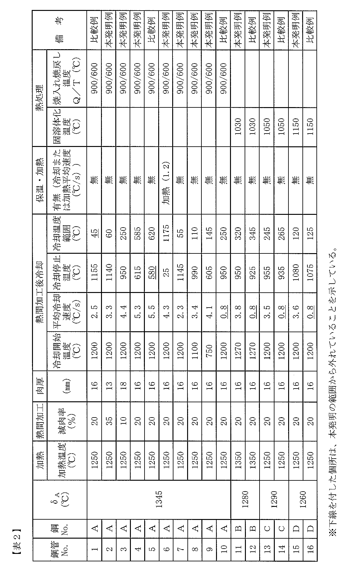
- these steel materials are charged into the heating apparatus 1, heated to the heating temperature shown in Table 2, and held for a certain time (60 min).
- piercing and rolling is performed using the barrel type Mannesmann piercing and rolling device 2 to obtain a hollow material (thickness 20 mm).
- the test piece was extract
- the test method was as follows. (1) Microstructure observation From the obtained seamless steel pipe, first, the presence or absence of cracking at the end of the steel pipe and the degree of cracking were evaluated visually. The case where there were 5 or more cracks was evaluated as “Yes”, and the case where it was less than that was evaluated as “Yes”. Next, a specimen for tissue observation was collected, and a cross section (C cross section) perpendicular to the tube axis direction was polished and corroded (corrosion liquid: Villella liquid).
- the tissue is observed with an optical microscope (magnification: 200 times) or a scanning electron microscope (magnification: 1000 times), imaged, and image analysis is used to determine the type of tissue. It was measured. Further, as an index of refinement, the number of phase boundaries intersecting with a straight line of unit length was measured from a structure photograph.
- the numerical value of the obtained phase boundary of each steel pipe is the same as the above-mentioned phase boundary of the steel pipe whose cooling after hot working is allowed to cool (cooling rate: 0.8 ° C./s). Each numerical value was set as a reference (1.00) and expressed as a ratio (phase boundary number ratio) to the reference value.
- the structure can be refined, and the strength improvement effect of 2.5% or more and the absorption energy improvement effect of 20% or more can be obtained, compared with the case of cooling after hot working, yielding.
- Strength YS A duplex stainless steel pipe having a high strength of 588 MPa or more can be produced without causing cracks.
Landscapes
- Chemical & Material Sciences (AREA)
- Engineering & Computer Science (AREA)
- Mechanical Engineering (AREA)
- Materials Engineering (AREA)
- Metallurgy (AREA)
- Organic Chemistry (AREA)
- Physics & Mathematics (AREA)
- Thermal Sciences (AREA)
- Crystallography & Structural Chemistry (AREA)
- Manufacturing & Machinery (AREA)
- Heat Treatment Of Steel (AREA)
- Heat Treatment Of Articles (AREA)
Abstract
Description
但し、Rd:断面減少率での加工度(%)、MYS:目標降伏強度(MPa)、Cr、Mo、WおよびN:それぞれの元素の含有量(質量%)。
(1)継目無鋼管製造用装置列であって、
鋼素材を加熱する加熱装置と、
加熱された前記鋼素材に穿孔圧延(piercing)を施し中空素材(hollow material)とする穿孔圧延装置と、
前記中空素材に熱間加工を施し所定寸法の継目無鋼管とする圧延装置と、
前記圧延装置の出側に冷却装置とを有することを特徴とする継目無鋼管製造用装置列。
(2)前記冷却装置の出側に加熱機能を有する保温(heat‐retention)装置を配設することを特徴とする(1)に記載の継目無鋼管製造用装置列。
(3)前記冷却装置が、被冷却材の外表面位置の平均冷却速度を1.0℃/s以上とする冷却能を有することを特徴とする(1)または(2)に記載の継目無鋼管製造用装置列。
(4)前記保温装置が、被保温処理材の外表面位置の平均冷却速度を1.0℃/s以下とする保温能を有することを特徴とする(2)または(3)に記載の継目無鋼管製造用装置列。
(5)前記保温装置が、加熱する場合には被加熱処理材の外表面位置の平均加熱速度を1.0℃/s以上とする加熱能を有することを特徴とする(2)または(3)に記載の継目無鋼管製造用装置列。
(6)前記保温装置が、加熱する場合には被加熱処理材の外表面位置の平均加熱速度を1.0℃/s以上とする加熱能を有することを特徴とする(4)に記載の継目無鋼管製造用装置列。
(7)(1)ないし(6)のいずれか1項に記載の継目無鋼管製造用装置列を利用した二相ステンレス継目無鋼管の製造方法であって、
鋼素材を前記加熱装置で加熱し、
前記穿孔圧延装置で穿孔圧延を施して中空素材とし、
該中空素材に前記圧延装置で熱間加工を施して素管とし、
該素管を前記冷却装置で冷却することとし、
前記鋼素材を、質量%で、
C:0.050%以下、 Si:2.00%以下、
Mn:5.00%以下、 P:0.05%以下、
S:0.03%以下 Cr:16.0~35.0%、
Ni:3.0~12.0%、 Mo:5.0%以下、
Al:0.1%以下、 N:0.5%以下、
を含み、残部Feおよび不可避的不純物(unavoidable impurities)からなる組成を有する鋼素材とし、
前記加熱装置で、(δA-300℃)~(δA+100℃)の温度に前記鋼素材を加熱し、
前記圧延装置で熱間加工を施し、
前記冷却装置で冷却する前の前記素管の表面温度を冷却開始温度として、前記冷却装置では、表面温度で、前記冷却開始温度からの温度差が少なくとも50℃以上で、かつ冷却停止温度が600℃以上となる冷却停止温度まで、外表面温度で1.0℃/s以上の平均冷却速度で冷却することを特徴とする二相ステンレス継目無鋼管の製造方法。
(8)(7)に記載の二相ステンレス継目無鋼管の製造方法であって、前記冷却後に前記素管を前記保温装置を通過させることを特徴とする二相ステンレス継目無鋼管の製造方法。
(9)前記保温装置内を通過させる処理が、前記素管の外表面位置の平均冷却速度で1.0℃/s以下の冷却となるように調整することを特徴とする(8)に記載の二相ステンレス継目無鋼管の製造方法。
(10)前記保温装置による前記素管の外表面位置の平均加熱速度が1.0℃/s以上であることを特徴とする請求項(8)または(9)に記載の二相ステンレス継目無鋼管の製造方法。
(11)前記組成に加えてさらに、質量%で、Nb:3.0%以下、Ti:0.1%以下、V:3.0%以下、Zr:0.5%以下、W:3.5%以下、Cu:3.5%以下、REM:0.05%以下、B:0.01%以下、Ca:0.1%以下のうちから選ばれた1種または2種以上を含有することを特徴とする(7)ないし(10)のいずれか1項に記載の二相ステンレス継目無鋼管の製造方法。
Cは、強度を増加させる元素であるが、耐食性を低下させるため、できるだけ低減することが望ましい。ただし、過度の低減は製造コストの高騰を招く。このため、本発明では、0.05%以下に限定した。なお、好ましくは0.03%以下である。
Siは、脱酸剤(deoxidant)として作用するとともに、強度を向上させる元素であり、このような効果を得るためには0.01%以上含有することが望ましい。ただし、2.00%を超える多量の含有は、延性の低下や、金属間化合物の析出を助長し、耐食性を低下させる。このため、Siは2.0%以下に限定した。なお、好ましくは0.5~1.5%である。
Mnは、オーステナイト安定化元素(stabilizing element)であり、二相組織の分率を適正に調整し、二相ステンレス鋼材の耐食性と加工性の向上に寄与する。このような効果を得るためには、0.01%以上の含有が望ましい。ただし、5.0%を超える含有は、熱間加工性、耐食性を低下させる。このため、Mnは5.0%以下に限定した。なお、好ましくは0.5~2.0%である。
Pは、不純物(impurities)として混入する元素であり、結晶粒界(grain boundary)等に偏析(segregation)しやすく、耐食性や熱間加工性の低下を招くため、できるだけ低減することが望ましいが、0.05%までは許容できる。しかし、過度の低減は、材料コストの高騰を招くため、0.002%以上とすることが好ましい。このようなことから、Pは0.05%以下に限定した。なお、好ましくは0.02%以下である。
Sは、Pと同様に、不純物として混入する元素であり、鋼中では硫化物系介在物(inclusion)として存在し、延性(ductility)、耐食性、熱間加工性を低下させるため、できるだけ低減することが好ましいが、0.03%までは許容できる。しかし、過度の低減は、材料コストの高騰を招くため、0.002%以上とすることが好ましい。このようなことから、Sは0.03%以下に限定した。なお、好ましくは0.005%以下である。
Niは、オーステナイト安定化元素であり、二相組織の分率を適正に調整し、二相ステンレス鋼材の耐食性と加工性の向上に寄与する。このような効果を得るためには、3.0%以上の含有を必要とする。一方、12.0%を超える含有は、過度のオーステナイト相の増加を招き、所望の二相組織を維持することが困難となる。このため、Niは3.0~12.0%の範囲に限定した。なお、好ましくは5.0~9.0%である。
Crは、耐食性を向上させる元素であり、かつフェライト安定化元素であってフェライト相とオーステナイト相の二相組織の分率を決める主要な元素である。このような効果を得るためには16.0%以上の含有を必要とする。一方、35.0%を超えて多量に含有すると、σ相、χ相等の金属間化合物の生成を助長し、耐食性の低下を招く。このため、Crは16.0~35.0%の範囲に限定した。なお、好ましくは16.0~28.0%である。
Moは、耐食性を向上させる元素であり、このような効果を得るためには、1.0%以上含有することが望ましい。一方、5.0%を超えて含有すると、金属間化合物の析出を助長し、耐食性、熱間加工性を低下させる。このため、Moは5.0%以下に限定した。なお、好ましくは2.0~4.0%である。
Alは、脱酸剤として作用する元素であり、このような効果を得るためには、0.001%以上含有することが望ましい。ただし、0.1%を超えて多量に含有すると、酸化物系(oxide‐based)介在物量が増加し、清浄度(cleanliness)の低下を招く。このため、Alは0.1%以下に限定した。なお、好ましくは0.001~0.050%である。
Nは、強力なオーステナイト安定化元素であり、耐食性向上にも寄与する。このような効果を得るためには、0.050%以上含有することが望ましい。一方、0.5%を超えて含有すると、過度のオーステナイト相の増加を招き、所望の二相組織を維持することが困難となる。このため、Nは0.5%以下に限定した。
以上を含有してもよい。
が好ましい。
加熱温度が、(δA-300℃)未満では、フェライト相からの変態を利用した組織の微細化を達成できない。また、オーステナイト相分率(phase fraction)が上昇し、荷重(load)増加や熱間延性の低下により加工が困難になる。一方、加熱温度が(δA+100℃)以上では、加工による歪の蓄積が困難となる。このため、鋼素材の加熱温度は(δA-300℃)~(δA+100℃)の温度に限定した。なお、好ましくは1100~1300℃である。また、δAは、汎用の平衡状態(equilibrium state)計算ソフトを用いて求めても良いし、または、熱膨張曲線(thermal expansion curve)を測定し、δフェライト相変態完了による熱膨張曲線の変曲点(inflection point)から求めても良い。
本発明では、冷却処理は、加工歪が蓄積された過冷却(super-cooled)状態のフェライト相(非平衡状態の相分布)を得るために、被冷却材(素管)の外表面位置で、少なくとも1.0℃/s以上の平均冷却速度で冷却するものとする。上記した平均冷却速度より遅い冷却しかできない場合には、前記加工歪が回復するとともに、フェライト相粒界や粒内(grain)からオーステナイト相やその他の析出相が平衡状態に近づくように析出し、非平衡状態の相分布を得ることができず、組織の微細化ができなくなる。なお、冷却速度の上限は、とくに限定する必要はないが、熱応力による割れや曲り防止という観点から、50℃/sとすることが好ましい。好ましくは3~30℃/sである。
冷却の温度範囲、すなわち、冷却開始温度と冷却停止温度の温度差は、少なくとも被冷却材(素管)の外表面温度で50℃以上とする。冷却の温度範囲が50℃未満では、過冷却フェライト相の分率が小さく、顕著な非平衡状態の相分率を確保できなくなり、所望の組織微細化を達成できない。このため、冷却の温度範囲は50℃以上に限定した。冷却の温度範囲は大きいほど、非平衡状態の相分率を確保できやすくなる。なお、好ましくは100℃以上である。なお、冷却開始温度とは、冷却開始前の被冷却材(素管)の外表面温度である。
冷却停止温度が600℃未満では、元素の拡散が遅くなり、その後の保持中に起こる相変態(α→γ変態)が遅れ、所望の微細組織を確保するには長時間を要し、生産性が低下する。このため、冷却停止温度は被冷却材(素管)の肉厚中心温度で600℃以上に限定した。なお、好ましくは700℃以上である。
冷却装置4による冷却停止後の被冷却材(素管)の外表面位置での平均冷却速度が1.0℃/sを超える冷却となる場合には、被冷却材(素管)を冷却装置4の出側に設置された保温装置5に装入し、前記平均冷却速度を1.0℃/s以下に調整することが好ましい。冷却停止後の被冷却材(素管)の外表面位置での平均冷却速度が1.0℃/sを超えて速くなりすぎると、第二相(second phase)の析出が不十分となり製品時に所望の相分率が得られない。
冷却停止温度が600℃を下回った場合には、その後、保温装置5を用いて被加熱処理材(素管)の外表面温度で1.0℃/s以上の加熱速度で600℃以上、1150℃未満の温度域に加熱すれば冷却停止温度が600℃を下回らない条件と同様の効果が得られる。加熱速度の上限は特に規定する必要は無いが、全体を均一に加熱するために50℃/s以下の加熱速度であることが好ましい。
(1)組織観察
得られた継目無鋼管から、まず目視で、鋼管端部における割れ発生の有無、および割れが発生している場合にはその程度を評価した。割れ発生箇所が5箇所以上である場合を「有;多」とし、それ未満である場合を「有;少」と評価した。
次に、組織観察用試験片を採取し、管軸方向に直交する断面(C断面)を研磨、腐食(腐食液:ビレラ液(Villella liquid))した。次に、光学顕微鏡(倍率:200倍)または走査型電子顕微鏡(scanning electron microscope)(倍率:1000倍)で組織を観察し、撮像して、画像解析(image analysis)を用い、組織の種類を測定した。また、微細化の指標として、組織写真から、単位長さの直線と交差する相境界の数を測定した。なお、表3では、得られた各鋼管の前記相境界の数値を、同一鋼種で熱間加工後の冷却が放冷(冷却速度:0.8℃/s)である鋼管の前記相境界の数値をそれぞれ基準(1.00)として、基準値に対する比率(相境界数比)として示した。
(2)引張試験
得られた継目無鋼管から、管軸方向が引張方向となるように、丸棒引張試験片(平行部6mmφ×GL20mm)を採取し、JIS Z 2241の規定に準拠して引張試験を実施し、降伏強さYSを求めた。なお、降伏強さは0.2%伸びでの強度とした。得られた降伏強さと、同一鋼種で熱間加工後の冷却が放冷(冷却速度:0.8℃/s)である鋼管の降伏強さ(基準降伏強さ)との差を、基準降伏強さで除した値(%)、ΔYS(%)(=(降伏強さ-基準降伏強さ)×100/(基準降伏強さ)を算出し、各鋼管の強度向上率を評価した。また、降伏強さYSが588MPaを下回ったものは×、上回ったものは○とした。
(3)シャルピー試験
得られた継目無鋼管から、試験片の長手方向が、管軸方向と直交する方向(C方向)となるように、シャルピー衝撃試験片(Vノッチ試験片)を採取し、JIS Z 2242の規定に準拠して、シャルピー衝撃試験を実施し、試験温度:-10℃での吸収エネルギーvE-10(J)を求めた。なお、試験は、各3本の試験片で行い、それらの算術平均を求め、当該鋼管の値とした。その結果得られた各鋼管の吸収エネルギー値と同一鋼種で熱間加工後の冷却が放冷(冷却速度:0.8℃/s)である鋼管の吸収エネルギー値(基準吸収エネルギー値)との差を、基準吸収エネルギー値で除した値(%)、ΔE(%)(=(吸収エネルギー値-基準吸収エネルギー値)×100/(基準吸収エネルギー値)を算出し、各鋼管の吸収エネルギー向上率を評価した。


2 穿孔圧延装置
3 圧延装置
4 冷却装置
5 保温装置
31 エロンゲータ
32 プラグミル
33 サイザー
Claims (11)
- 継目無鋼管製造用装置列であって、
鋼素材を加熱する加熱装置と、
加熱された前記鋼素材に穿孔圧延を施し中空素材とする穿孔圧延装置と、
前記中空素材に熱間加工を施し所定寸法の継目無鋼管とする圧延装置と、
前記圧延装置の出側に冷却装置とを有することを特徴とする継目無鋼管製造用装置列。 - 前記冷却装置の出側に加熱機能を有する保温装置を配設することを特徴とする請求項1に記載の継目無鋼管製造用装置列。
- 前記冷却装置が、被冷却材の外表面位置の平均冷却速度を1.0℃/s以上とする冷却能を有することを特徴とする請求項1または2に記載の継目無鋼管製造用装置列。
- 前記保温装置が、被保温処理材の外表面位置の平均冷却速度を1.0℃/s以下とする保温能を有することを特徴とする請求項2または3に記載の継目無鋼管製造用装置列。
- 前記保温装置が、加熱する場合には被加熱処理材の外表面位置の平均加熱速度を1.0℃/s以上とする加熱能を有することを特徴とする請求項2または3に記載の継目無鋼管製造用装置列。
- 前記保温装置が、加熱する場合には被加熱処理材の外表面位置の平均加熱速度を1.0℃/s以上とする加熱能を有することを特徴とする請求項4に記載の継目無鋼管製造用装置列。
- 請求項1ないし6のいずれか1項に記載の継目無鋼管製造用装置列を利用した二相ステンレス継目無鋼管の製造方法であって、
鋼素材を前記加熱装置で加熱し、
前記穿孔圧延装置で穿孔圧延を施して中空素材とし、
該中空素材に前記圧延装置で熱間加工を施して素管とし、
該素管を前記冷却装置で冷却することとし、
前記鋼素材を、質量%で、
C:0.050%以下、 Si:2.00%以下、
Mn:5.00%以下、 P:0.05%以下、
S:0.03%以下 Cr:16.0~35.0%、
Ni:3.0~12.0%、 Mo:5.0%以下、
Al:0.1%以下、 N:0.5%以下、
を含み、残部Feおよび不可避的不純物からなる組成を有する鋼素材とし、
前記加熱装置で、(δA-300℃)~(δA+100℃)の温度に前記鋼素材を加熱し、
前記圧延装置で熱間加工を施し、
前記冷却装置で冷却する前の前記素管の表面温度を冷却開始温度として、前記冷却装置では、表面温度で、前記冷却開始温度からの温度差が少なくとも50℃以上で、かつ冷却停止温度が600℃以上となる冷却停止温度まで、外表面温度で1.0℃/s以上の平均冷却速度で冷却することを特徴とする二相ステンレス継目無鋼管の製造方法。 - 請求項7に記載の二相ステンレス継目無鋼管の製造方法であって、前記冷却後に前記素管を前記保温装置を通過させることを特徴とする二相ステンレス継目無鋼管の製造方法。
- 前記保温装置内を通過させる処理が、前記素管の外表面位置の平均冷却速度で1.0℃/s以下の冷却となるように調整することを特徴とする請求項8に記載の二相ステンレス継目無鋼管の製造方法。
- 前記保温装置による前記素管の外表面位置の平均加熱速度が1.0℃/s以上であることを特徴とする請求項8または9に記載の二相ステンレス継目無鋼管の製造方法。
- 前記組成に加えてさらに、質量%で、Nb:3.0%以下、Ti:0.1%以下、V:3.0%以下、Zr:0.5%以下、W:3.5%以下、Cu:3.5%以下、REM:0.05%以下、B:0.01%以下、Ca:0.1%以下のうちから選ばれた1種または2種以上を含有することを特徴とする請求項7ないし10のいずれか1項に記載の二相ステンレス継目無鋼管の製造方法。
Priority Applications (6)
| Application Number | Priority Date | Filing Date | Title |
|---|---|---|---|
| EP15863394.1A EP3225318B1 (en) | 2014-11-27 | 2015-10-07 | Manufacturing method for duplex stainless steel seamless pipe or tube using a device array for manufacturing seamless steel pipe or tube |
| MX2017006869A MX2017006869A (es) | 2014-11-27 | 2015-10-07 | Linea de aparato para fabricar tuberia y tubo de acero sin costura y metodo para fabricar tuberia de acero inoxidable sin costura duplex. |
| BR112017011002-4A BR112017011002B1 (pt) | 2014-11-27 | 2015-10-07 | Método de fabricação para cano ou tubo sem costura de aço inoxidável duplex |
| US15/529,842 US10544476B2 (en) | 2014-11-27 | 2015-10-07 | Apparatus line for manufacturing seamless steel pipe and tube and method of manufacturing duplex seamless stainless steel pipe |
| JP2016502545A JP6008062B1 (ja) | 2014-11-27 | 2015-10-07 | 二相ステンレス継目無鋼管の製造方法 |
| US16/708,997 US11821051B2 (en) | 2014-11-27 | 2019-12-10 | Apparatus line for manufacturing seamless steel pipe and tube and method of manufacturing duplex seamless stainless steel pipe |
Applications Claiming Priority (2)
| Application Number | Priority Date | Filing Date | Title |
|---|---|---|---|
| JP2014-239449 | 2014-11-27 | ||
| JP2014239449 | 2014-11-27 |
Related Child Applications (2)
| Application Number | Title | Priority Date | Filing Date |
|---|---|---|---|
| US15/529,842 A-371-Of-International US10544476B2 (en) | 2014-11-27 | 2015-10-07 | Apparatus line for manufacturing seamless steel pipe and tube and method of manufacturing duplex seamless stainless steel pipe |
| US16/708,997 Division US11821051B2 (en) | 2014-11-27 | 2019-12-10 | Apparatus line for manufacturing seamless steel pipe and tube and method of manufacturing duplex seamless stainless steel pipe |
Publications (1)
| Publication Number | Publication Date |
|---|---|
| WO2016084298A1 true WO2016084298A1 (ja) | 2016-06-02 |
Family
ID=56073897
Family Applications (1)
| Application Number | Title | Priority Date | Filing Date |
|---|---|---|---|
| PCT/JP2015/005095 Ceased WO2016084298A1 (ja) | 2014-11-27 | 2015-10-07 | 継目無鋼管製造用装置列およびそれを利用した二相ステンレス継目無鋼管の製造方法 |
Country Status (6)
| Country | Link |
|---|---|
| US (2) | US10544476B2 (ja) |
| EP (1) | EP3225318B1 (ja) |
| JP (1) | JP6008062B1 (ja) |
| AR (1) | AR102784A1 (ja) |
| MX (1) | MX2017006869A (ja) |
| WO (1) | WO2016084298A1 (ja) |
Cited By (1)
| Publication number | Priority date | Publication date | Assignee | Title |
|---|---|---|---|---|
| CN108660373A (zh) * | 2018-05-11 | 2018-10-16 | 上海申江锻造有限公司 | 一种高强度奥氏体不锈钢叶轮轴的制造方法 |
Families Citing this family (8)
| Publication number | Priority date | Publication date | Assignee | Title |
|---|---|---|---|---|
| JP6341181B2 (ja) * | 2015-03-25 | 2018-06-13 | Jfeスチール株式会社 | 二相ステンレス継目無鋼管の製造方法 |
| MX378757B (es) * | 2016-02-08 | 2025-03-11 | Jfe Steel Corp | Tubo de acero inoxidable sin costura de alta resistencia para productos tubulares para la industria del petróleo y método de fabricación de tubo de acero inoxidable sin costura de alta resistencia. |
| JP6510714B1 (ja) | 2018-08-08 | 2019-05-08 | 日本冶金工業株式会社 | 低温靭性に優れる二相ステンレス鋼 |
| CN110404973A (zh) * | 2019-07-15 | 2019-11-05 | 扬州诚德钢管有限公司 | 一种直径为760mm~914mm的无缝钢管的制造方法 |
| CN110404972B (zh) * | 2019-07-15 | 2021-03-02 | 扬州诚德钢管有限公司 | 一种直径为1422mm的无缝钢管的生产方法 |
| JP7226571B2 (ja) * | 2020-07-06 | 2023-02-21 | Jfeスチール株式会社 | ステンレス継目無鋼管およびその製造方法 |
| CN114932146B (zh) * | 2022-06-30 | 2024-09-10 | 浙江青山钢铁有限公司 | 一种超级双相不锈钢线材的轧制方法 |
| CN119776737B (zh) * | 2025-03-11 | 2025-07-01 | 上海宇洋特种金属材料有限公司 | 一种耐磨焊管用钢及其制备方法和焊管 |
Citations (4)
| Publication number | Priority date | Publication date | Assignee | Title |
|---|---|---|---|---|
| JPH03267316A (ja) * | 1990-03-19 | 1991-11-28 | Sumitomo Metal Ind Ltd | 超微細組織を有する継目無鋼管の製造法 |
| WO2007114077A1 (ja) * | 2006-03-31 | 2007-10-11 | Sumitomo Metal Industries, Ltd. | 二相ステンレス鋼継目無管の製造方法 |
| JP2013031865A (ja) * | 2011-08-01 | 2013-02-14 | Nippon Steel & Sumitomo Metal Corp | 強度と低温靱性に優れた継目無鋼管の制御圧延方法 |
| JP2015086412A (ja) * | 2013-10-29 | 2015-05-07 | Jfeスチール株式会社 | 継目無鋼管製造用装置列およびそれを利用した油井用高強度ステンレス継目無鋼管の製造方法 |
Family Cites Families (17)
| Publication number | Priority date | Publication date | Assignee | Title |
|---|---|---|---|---|
| JPS5891123A (ja) | 1981-11-27 | 1983-05-31 | Kawasaki Steel Corp | 溶接部靭性に優れた80kg/mm↑2級構造用継目無鋼管の製造方法 |
| JPH07207337A (ja) | 1994-01-21 | 1995-08-08 | Sumitomo Metal Ind Ltd | 高強度2相ステンレス鋼材の製造方法 |
| JPH0890043A (ja) | 1994-09-26 | 1996-04-09 | Sumitomo Metal Ind Ltd | ステンレス継目無鋼管の製造方法 |
| US5938865A (en) * | 1995-05-15 | 1999-08-17 | Sumitomo Metal Industries, Ltc. | Process for producing high-strength seamless steel pipe having excellent sulfide stress cracking resistance |
| JP3855300B2 (ja) | 1996-04-19 | 2006-12-06 | 住友金属工業株式会社 | 継目無鋼管の製造方法および製造設備 |
| TW458819B (en) * | 1999-05-24 | 2001-10-11 | Nippon Steel Corp | Apparatus for continuous production of steel wire |
| CN1840287A (zh) * | 2005-03-31 | 2006-10-04 | 住友金属工业株式会社 | 高强度高韧性管道用无缝钢管的制造方法 |
| BRPI0710119B1 (pt) * | 2006-03-28 | 2019-04-02 | Nippon Steel & Sumitomo Metal Corporation | Método de fabricação de tubulação e tubo sem costura |
| JP4462454B1 (ja) | 2009-01-19 | 2010-05-12 | 住友金属工業株式会社 | 二相ステンレス鋼管の製造方法 |
| MX2012007817A (es) * | 2010-01-05 | 2012-11-30 | Sms Innse Spa | Planta de enrollamiento de tubo. |
| AU2011210499B2 (en) * | 2010-01-27 | 2013-07-11 | Nippon Steel Corporation | Production method for seamless steel pipe used in line pipe, and seamless steel pipe used in line pipe |
| MX360028B (es) * | 2010-03-18 | 2018-10-17 | Nippon Steel & Sumitomo Metal Corp Star | Tubo de acero sin costuras para inyeccion de vapor y metodo para fabricar el mismo. |
| MX342030B (es) * | 2010-06-02 | 2016-09-08 | Nippon Steel & Sumitomo Metal Corp * | Tubo de acero sin costuras para tubería y método para fabricar el mismo. |
| MX355667B (es) * | 2012-04-27 | 2018-04-25 | Nippon Steel & Sumitomo Metal Corp | Tuberia de acero sin soldadura y metodo para producir la misma. |
| JP5488643B2 (ja) * | 2012-05-31 | 2014-05-14 | Jfeスチール株式会社 | 油井管用高強度ステンレス鋼継目無管およびその製造方法 |
| JP5891123B2 (ja) | 2012-06-27 | 2016-03-22 | 川澄化学工業株式会社 | 医療用針安全装置 |
| EP2789700A1 (en) * | 2013-04-08 | 2014-10-15 | DALMINE S.p.A. | Heavy wall quenched and tempered seamless steel pipes and related method for manufacturing said steel pipes |
-
2015
- 2015-10-07 JP JP2016502545A patent/JP6008062B1/ja active Active
- 2015-10-07 EP EP15863394.1A patent/EP3225318B1/en active Active
- 2015-10-07 US US15/529,842 patent/US10544476B2/en active Active
- 2015-10-07 WO PCT/JP2015/005095 patent/WO2016084298A1/ja not_active Ceased
- 2015-10-07 MX MX2017006869A patent/MX2017006869A/es unknown
- 2015-11-25 AR ARP150103852A patent/AR102784A1/es active IP Right Grant
-
2019
- 2019-12-10 US US16/708,997 patent/US11821051B2/en active Active
Patent Citations (4)
| Publication number | Priority date | Publication date | Assignee | Title |
|---|---|---|---|---|
| JPH03267316A (ja) * | 1990-03-19 | 1991-11-28 | Sumitomo Metal Ind Ltd | 超微細組織を有する継目無鋼管の製造法 |
| WO2007114077A1 (ja) * | 2006-03-31 | 2007-10-11 | Sumitomo Metal Industries, Ltd. | 二相ステンレス鋼継目無管の製造方法 |
| JP2013031865A (ja) * | 2011-08-01 | 2013-02-14 | Nippon Steel & Sumitomo Metal Corp | 強度と低温靱性に優れた継目無鋼管の制御圧延方法 |
| JP2015086412A (ja) * | 2013-10-29 | 2015-05-07 | Jfeスチール株式会社 | 継目無鋼管製造用装置列およびそれを利用した油井用高強度ステンレス継目無鋼管の製造方法 |
Non-Patent Citations (1)
| Title |
|---|
| See also references of EP3225318A4 * |
Cited By (1)
| Publication number | Priority date | Publication date | Assignee | Title |
|---|---|---|---|---|
| CN108660373A (zh) * | 2018-05-11 | 2018-10-16 | 上海申江锻造有限公司 | 一种高强度奥氏体不锈钢叶轮轴的制造方法 |
Also Published As
| Publication number | Publication date |
|---|---|
| JPWO2016084298A1 (ja) | 2017-04-27 |
| MX2017006869A (es) | 2017-08-14 |
| US20170335422A1 (en) | 2017-11-23 |
| EP3225318A1 (en) | 2017-10-04 |
| US10544476B2 (en) | 2020-01-28 |
| EP3225318A4 (en) | 2017-12-27 |
| AR102784A1 (es) | 2017-03-22 |
| JP6008062B1 (ja) | 2016-10-19 |
| BR112017011002A8 (pt) | 2022-11-01 |
| BR112017011002A2 (ja) | 2018-01-09 |
| EP3225318B1 (en) | 2024-08-21 |
| US20200109460A1 (en) | 2020-04-09 |
| US11821051B2 (en) | 2023-11-21 |
Similar Documents
| Publication | Publication Date | Title |
|---|---|---|
| JP6197850B2 (ja) | 二相ステンレス継目無鋼管の製造方法 | |
| JP6008062B1 (ja) | 二相ステンレス継目無鋼管の製造方法 | |
| JP4632000B2 (ja) | 継目無鋼管の製造方法 | |
| JP4462454B1 (ja) | 二相ステンレス鋼管の製造方法 | |
| JP5387799B1 (ja) | 耐硫化物応力割れ性に優れた高強度鋼材の製造方法 | |
| JP6635194B2 (ja) | 継目無鋼管及びその製造方法 | |
| JP6341125B2 (ja) | 2相ステンレス継目無鋼管の製造方法 | |
| JP2016164288A (ja) | 油井用高強度ステンレス継目無鋼管の製造方法 | |
| JP6686320B2 (ja) | ステンレス鋼管の製造方法 | |
| JP6171851B2 (ja) | 継目無鋼管製造用装置列およびそれを利用した油井用高強度ステンレス継目無鋼管の製造方法 | |
| JP5915818B2 (ja) | サワー環境で使用されるラインパイプ用継目無鋼管 | |
| JP6341128B2 (ja) | 油井用薄肉高強度ステンレス継目無鋼管の製造方法 | |
| JP2018035381A (ja) | ステンレス鋼管の製造方法 | |
| JP6206423B2 (ja) | 低温靭性に優れた高強度ステンレス厚鋼板およびその製造方法 | |
| JP6137082B2 (ja) | 低温靭性に優れた油井用高強度ステンレス継目無鋼管およびその製造方法 | |
| WO2020090149A1 (ja) | ボルト用鋼及びその製造方法 | |
| JP6341181B2 (ja) | 二相ステンレス継目無鋼管の製造方法 | |
| JP6202010B2 (ja) | 高強度2相ステンレス継目無鋼管の製造方法 | |
| JP2016108628A (ja) | 二相ステンレス鋼材の製造方法 | |
| JP6171834B2 (ja) | 厚肉鋼材製造用装置列 | |
| BR112017011002B1 (pt) | Método de fabricação para cano ou tubo sem costura de aço inoxidável duplex |
Legal Events
| Date | Code | Title | Description |
|---|---|---|---|
| ENP | Entry into the national phase |
Ref document number: 2016502545 Country of ref document: JP Kind code of ref document: A |
|
| 121 | Ep: the epo has been informed by wipo that ep was designated in this application |
Ref document number: 15863394 Country of ref document: EP Kind code of ref document: A1 |
|
| REEP | Request for entry into the european phase |
Ref document number: 2015863394 Country of ref document: EP |
|
| WWE | Wipo information: entry into national phase |
Ref document number: MX/A/2017/006869 Country of ref document: MX |
|
| NENP | Non-entry into the national phase |
Ref country code: DE |
|
| REG | Reference to national code |
Ref country code: BR Ref legal event code: B01A Ref document number: 112017011002 Country of ref document: BR |
|
| ENP | Entry into the national phase |
Ref document number: 112017011002 Country of ref document: BR Kind code of ref document: A2 Effective date: 20170525 |