WO2016084701A1 - マイクロニードルデバイス - Google Patents
マイクロニードルデバイス Download PDFInfo
- Publication number
- WO2016084701A1 WO2016084701A1 PCT/JP2015/082552 JP2015082552W WO2016084701A1 WO 2016084701 A1 WO2016084701 A1 WO 2016084701A1 JP 2015082552 W JP2015082552 W JP 2015082552W WO 2016084701 A1 WO2016084701 A1 WO 2016084701A1
- Authority
- WO
- WIPO (PCT)
- Prior art keywords
- microneedle
- drug
- skin
- microneedle device
- height
- Prior art date
- Legal status (The legal status is an assumption and is not a legal conclusion. Google has not performed a legal analysis and makes no representation as to the accuracy of the status listed.)
- Ceased
Links
Images


Classifications
-
- A—HUMAN NECESSITIES
- A61—MEDICAL OR VETERINARY SCIENCE; HYGIENE
- A61K—PREPARATIONS FOR MEDICAL, DENTAL OR TOILETRY PURPOSES
- A61K9/00—Medicinal preparations characterised by special physical form
- A61K9/0012—Galenical forms characterised by the site of application
- A61K9/0019—Injectable compositions; Intramuscular, intravenous, arterial, subcutaneous administration; Compositions to be administered through the skin in an invasive manner
- A61K9/0021—Intradermal administration, e.g. through microneedle arrays or needleless injectors
-
- A—HUMAN NECESSITIES
- A61—MEDICAL OR VETERINARY SCIENCE; HYGIENE
- A61M—DEVICES FOR INTRODUCING MEDIA INTO, OR ONTO, THE BODY; DEVICES FOR TRANSDUCING BODY MEDIA OR FOR TAKING MEDIA FROM THE BODY; DEVICES FOR PRODUCING OR ENDING SLEEP OR STUPOR
- A61M37/00—Other apparatus for introducing media into the body; Percutany, i.e. introducing medicines into the body by diffusion through the skin
- A61M37/0015—Other apparatus for introducing media into the body; Percutany, i.e. introducing medicines into the body by diffusion through the skin by using microneedles
-
- B—PERFORMING OPERATIONS; TRANSPORTING
- B29—WORKING OF PLASTICS; WORKING OF SUBSTANCES IN A PLASTIC STATE IN GENERAL
- B29C—SHAPING OR JOINING OF PLASTICS; SHAPING OF MATERIAL IN A PLASTIC STATE, NOT OTHERWISE PROVIDED FOR; AFTER-TREATMENT OF THE SHAPED PRODUCTS, e.g. REPAIRING
- B29C67/00—Shaping techniques not covered by groups B29C39/00 - B29C65/00, B29C70/00 or B29C73/00
- B29C67/24—Shaping techniques not covered by groups B29C39/00 - B29C65/00, B29C70/00 or B29C73/00 characterised by the choice of material
- B29C67/242—Moulding mineral aggregates bonded with resin, e.g. resin concrete
- B29C67/243—Moulding mineral aggregates bonded with resin, e.g. resin concrete for making articles of definite length
-
- A—HUMAN NECESSITIES
- A61—MEDICAL OR VETERINARY SCIENCE; HYGIENE
- A61M—DEVICES FOR INTRODUCING MEDIA INTO, OR ONTO, THE BODY; DEVICES FOR TRANSDUCING BODY MEDIA OR FOR TAKING MEDIA FROM THE BODY; DEVICES FOR PRODUCING OR ENDING SLEEP OR STUPOR
- A61M37/00—Other apparatus for introducing media into the body; Percutany, i.e. introducing medicines into the body by diffusion through the skin
- A61M37/0015—Other apparatus for introducing media into the body; Percutany, i.e. introducing medicines into the body by diffusion through the skin by using microneedles
- A61M2037/0023—Drug applicators using microneedles
-
- A—HUMAN NECESSITIES
- A61—MEDICAL OR VETERINARY SCIENCE; HYGIENE
- A61M—DEVICES FOR INTRODUCING MEDIA INTO, OR ONTO, THE BODY; DEVICES FOR TRANSDUCING BODY MEDIA OR FOR TAKING MEDIA FROM THE BODY; DEVICES FOR PRODUCING OR ENDING SLEEP OR STUPOR
- A61M37/00—Other apparatus for introducing media into the body; Percutany, i.e. introducing medicines into the body by diffusion through the skin
- A61M37/0015—Other apparatus for introducing media into the body; Percutany, i.e. introducing medicines into the body by diffusion through the skin by using microneedles
- A61M2037/0046—Solid microneedles
-
- A—HUMAN NECESSITIES
- A61—MEDICAL OR VETERINARY SCIENCE; HYGIENE
- A61M—DEVICES FOR INTRODUCING MEDIA INTO, OR ONTO, THE BODY; DEVICES FOR TRANSDUCING BODY MEDIA OR FOR TAKING MEDIA FROM THE BODY; DEVICES FOR PRODUCING OR ENDING SLEEP OR STUPOR
- A61M37/00—Other apparatus for introducing media into the body; Percutany, i.e. introducing medicines into the body by diffusion through the skin
- A61M37/0015—Other apparatus for introducing media into the body; Percutany, i.e. introducing medicines into the body by diffusion through the skin by using microneedles
- A61M2037/0053—Methods for producing microneedles
Definitions
- the present invention relates to a microneedle device having fine protrusions for transdermally administering a drug.
- an oral administration method and a parenteral administration method have been used as a method for administering a drug.
- the method of oral administration is easy to administer the drug, but since the drug passes through the digestive system, it may not reach the affected area effectively depending on the type of drug.
- parenteral administration there are a method of administration by injection, and a method of transdermal administration such as a coating agent and a patch.
- Administration by injection is effective in that it can be administered directly into the body, but since the drug is injected directly into the skin or muscles with an injection needle, it usually causes pain and damages the skin and muscles. large.
- transdermal administration methods such as paints and patches are simple and painless, and the skin and muscles are not damaged, so the burden on the patient can be reduced.
- the skin has a biological barrier function that prevents the invasion of foreign substances.
- a highly lipophilic drug can penetrate the stratum corneum to some extent. The stratum corneum impedes penetration.
- Patent Documents As a method for transdermally administering a wide range of drugs, a method for transdermally administering a drug using a microneedle device having a large number of fine microneedles has been proposed (for example, Patent Documents). 1).
- the microneedle device has a wide range of pharmacological activities by puncturing the stratum corneum that prevents the penetration of the drug with fine needle-like microneedles with a height of several hundreds of ⁇ m and administering the drug directly to the epidermis, dermis, etc.
- the substance can be administered transdermally.
- the administration method of drugs using a microneedle device is very small compared to injection needles, etc., so there is almost no pain at the time of administration, and skin and muscle damage is small. The burden can be reduced.
- the microneedle device is difficult to adjust the puncture state because the microneedle is short, and the rate of drug transfer into the skin may not be as expected or may vary with each administration and may not be stable .
- the present invention has been made to solve the above-described problems, and an object of the present invention is to provide a microneedle device capable of stably increasing the drug transfer rate into the skin.
- a microneedle device that achieves the above object comprises a substrate, a microneedle that is a protrusion formed on the substrate and capable of puncturing the skin, and a drug applied to the microneedle.
- the aspect ratio which is the ratio of the height to the maximum width of the bottom surface, is 2.1 or more.
- the microneedle device configured as described above has an aspect ratio of 2.1 or more, the puncture ability of the microneedle is improved, and the transfer of the drug into the skin is performed more reliably, and the drug transfer rate is increased. It is possible to increase it stably.
- the medicine applied to the microneedle is arranged within a range of 50% of the height from the top of the microneedle in the height direction of the microneedle, it is difficult to enter the skin of the microneedle.
- the drug is not applied and the transfer efficiency of the drug can be stably increased.
- the microneedle Since the aspect ratio is 5 or less, the microneedle does not become too thin, and the occurrence of breakage or deformation of the microneedle can be suppressed.
- the microneedle device 10 is a device for transdermally administering a drug that is a pharmacologically active substance to the body by sticking to the skin.
- the microneedle device 10 includes a base 30, a microneedle 20 formed on the base 30, and a medicine 40 applied to the microneedle 20.
- the microneedle 20 is formed of a regular quadrangular pyramid, and is formed so as to become thinner from the bottom surface 22 on the base body 30 toward the top portion 21.
- the shape of the microneedle is not limited as long as it projects so as to become thin as a whole in the apex direction.
- the microneedle may be formed of other pyramids or cones having different numbers of angles.
- the tip shape of the top 21 of the microneedle 20 is not particularly limited as long as it can puncture the skin and provide a through-hole in the stratum corneum. Therefore, the top 21 of the microneedle 20 does not have to be formed with a perfect apex as shown in FIGS. 1 and 2 and may be formed with a curved surface or a plane that can puncture the skin.
- the height H of the microneedle 20 preferably does not reach the nerve of the dermis layer and can puncture the skin to administer the drug 40 to the inside of the stratum corneum, for example, 10 ⁇ m to 1500 ⁇ m. Within range. If the height H of the microneedle 20 is too short, it may be difficult to stably puncture the skin. If the height H of the microneedle 20 is too long, the microneedle 20 may become a nerve in the dermis layer. And the administration of drug 40 can be painful. Note that the microneedle 20 is referred to as a microneedle if the purpose can be achieved even when the height H exceeds 1000 ⁇ m (1 mm). Therefore, the microneedle device 10 including the microneedles 20 having a height H exceeding 1000 ⁇ m (1 mm) is also referred to as a microneedle device if the object can be achieved.
- the number per unit area of the microneedles 20 formed on the substrate 30 can be appropriately selected according to the use of the microneedle device 10 and the like, for example, within a range of 1 / cm 2 to 10,000 / cm 2. is there.
- the aspect ratio which is the ratio of the height H from the bottom surface 22 to the top 21 with respect to the maximum width L of the bottom surface 22 of the microneedle 20, is preferably 2.1 or more.
- the height H means a height in a direction perpendicular to the bottom surface 22 (or the base body 30).
- the maximum width L means the width of the widest portion of the bottom surface 22. Therefore, the maximum width L of the regular square weight matches the length of the diagonal line of the bottom surface 22.
- the aspect ratio is preferably 5 or less. If the aspect ratio exceeds 5, it may be difficult to maintain the strength of the thin microneedles 20.
- the maximum width L of the bottom surface 22 of the microneedle 20 can be appropriately set according to the height H of the microneedle 20 so that the aspect ratio is 2.1 or more.
- the range of the height direction in which the drug 40 of the microneedle 20 is applied is within the range of 50% of the height H from the top 21 of the microneedle 20, more preferably within the range of 40% of the height H from the top 21; More preferably, it is within the range of 30% of the height H from the top 21.
- the position where the medicine 40 is held is not limited to the above-described range, and may be held on the root side of the microneedle 20.
- the constituent material of the microneedle 20 is not particularly limited as long as the microneedle 20 can be formed, and a material used for a general microneedle device 10 can be applied.
- examples of the constituent material of the microneedle 20 include inorganic materials and resin materials.
- Inorganic materials include metals such as silicon, silicon dioxide, ceramic, stainless steel, iron, aluminum, titanium, nickel, molybdenum, chromium, cobalt, copper, lead, niobium, tantalum, zirconium, tin, gold, silver, etc. Can do.
- the resin material examples include biodegradable polymers such as polylactic acid, polyglycolide, polylactic acid-co-polyglycolide, pullulan, capronolactone, polyurethane, and polyanhydride.
- the resin material examples include non-degradable polymers such as polycarbonate, polymethacrylic acid, ethylene vinyl acetate, polytetrafluoroethylene, polyoxymethylene, cycloolefin polymer (COP), and cycloolefin copolymer (COC).
- the microneedle 20 is more preferably a liquid repellent material exhibiting liquid repellency among the materials described above. If the microneedle is made of a material with high wettability and low liquid repellency, the progress of the drug flowing toward the substrate cannot be suppressed, and a large amount of drug is applied near the root of the microneedle. There is a possibility. On the other hand, by imparting liquid repellency to the surface of the microneedle 20, when the drug 40 is applied to the microneedle 20, the progress of the drug 40 flowing from the top portion 21 toward the substrate can be favorably limited. .
- the material having liquid repellency include polycarbonate, polymethacrylic acid, ethylene vinyl acetate, polytetrafluoroethylene, polyoxymethylene, cycloolefin polymer (COP), and cycloolefin copolymer (COC).
- the microneedle 20 may have liquid repellency by performing an additional surface treatment such as a fluorine treatment.
- the microneedle 20 may be subjected to a surface treatment that increases wettability on the surface so that the drug 40 can be applied thinly on the surface.
- a surface treatment that increases wettability on the surface so that the drug 40 can be applied thinly on the surface.
- the process for increasing wettability include a process for roughening the surface and a plasma process.
- the microneedle 20 may be formed separately from the base body 30, but is usually formed integrally with the base body 30. A specific forming method will be described later.
- the base body 30 holds the bottom surface 22 of the microneedles 20 so that a plurality of microneedles 20 can be punctured into the skin all at once.
- the substrate 30 may be a separate body from the microneedles 20, but is usually formed integrally with the microneedles 20.
- the thickness of the substrate 30 is not particularly limited as long as the microneedles 20 can be held and has a strength that allows the microneedles 20 to be punctured into the skin.
- the thickness of the substrate 30 is in the range of 10 ⁇ m to 1500 ⁇ m. It is.
- the size, shape, and the like of the base body 30 are not particularly limited, and can be appropriately selected according to the use of the microneedle device 10 and the like.
- the constituent material of the substrate 30 can be the same as the material used for the microneedle 20 described above.
- the constituent material of the base 30 may be different from the material used for the microneedle 20.
- the manufacturing method of the microneedle device 10 according to the present embodiment is not particularly limited as long as the microneedle 20 can be formed on the substrate 30, and a method similar to a general microneedle manufacturing method is used. be able to. Specifically, an etching process, an electric discharge process, a sand blast process, a laser process, a hot emboss process, a machine cutting process, a plating process, an injection molding, an imprint molding, a photolithography method, and the like can be given.
- a method for manufacturing the microneedle device 10 by imprint molding will be specifically described.
- a stamper that is a mold having a recess corresponding to the shape of the microneedle 20 and a base material made of a material of the microneedle 20 such as a thermoplastic resin are prepared.
- the substrate is heated and softened, and a stamper is pressed on the surface of the softened substrate.
- the microneedle 20 having a shape corresponding to the recess is transferred to the surface of the substrate, and the microneedle device 10 is obtained.
- the stamper As the stamper, a known stamper generally used for manufacturing a microneedle device can be used.
- the stamper may be formed by subjecting a surface of a metal base material or the like to machining or the like.
- the stamper may be formed by performing etching or cutting on a metal base material or the like to form a master plate of the microneedle device 10 and then performing electroforming or the like on the master plate. Good.
- an ink jet method in which the drug 40 is applied by discharging the drug 40 from a position away from the microneedle 20 via a nozzle or the like, or the drug 40 is applied to the microneedle 20 via a nozzle or the like.
- examples thereof include a dispenser method to be applied, a dipping method (dipping method) in which the microneedle 20 is immersed in a drug, and the drug is attached.
- the dipping method is effective in order to intensively apply the drug 40 to the tip region of the microneedle 20.
- the immersion method as illustrated in FIG. 3, application is performed by immersing the microneedle 20 in the solution 41 containing the drug in the container 50 with the top portion 21 facing downward. Then, the layer of the medicine 40 is formed on the microneedle 20 by pulling up the microneedle 20 and volatilizing the solvent of the solution 41. At this time, the chemical
- the administration of the drug 40 using the microneedle device 10 is performed by puncturing the stratum corneum of the skin with the microneedle 20 coated with the drug 40 to open a through-hole in the stratum corneum, and the microneedle 20 from the through-hole to the lower layer of the stratum corneum. This is done by reaching the skin of the skin. Since the microneedle device 10 according to the present embodiment has an aspect ratio of 2.1 or more, the puncture ability is high, and the microneedle 20 easily reaches the epidermis or the like below the stratum corneum. For this reason, the medicine 40 can efficiently reach the lower layer of the stratum corneum and can be transferred without waste, and the drug transfer rate into the skin can be stably increased. By steadily increasing the rate of drug transfer into the skin, the drug administration rate does not easily change with each administration, so that the desired amount of drug can be administered at all times, and the drug can be effectively administered and is safe. Will also increase.
- the range of the height direction in which the drug 40 of the microneedle 20 is applied is within the range of 50% of the height H from the top 21 of the microneedle 20, it adheres to the stratum corneum at the time of puncturing.
- the amount of the drug 40 that is not transferred into the inside can be reduced, and the amount of the drug 40 that reaches the inside of the stratum corneum can be increased.
- the microneedle 20 is not too thin, the occurrence of breakage, deformation, etc. of the microneedle 20 can be suppressed, and the drug transfer rate into the skin can be stably increased.
- a microneedle device including a microneedle coated with a drug was prepared, and a test for verifying drug delivery using a rat was performed. (Example 1, Example 2)
- a microneedle device having 25 (5 ⁇ 5) regular quadrangular pyramid microneedles (aspect ratio: 2.12) with a base length of 167 ⁇ m and a height of 500 ⁇ m on a substrate, a cyclic polyolefin copolymer As a constituent material, it was produced by imprint molding.
- the drug to be applied to the microneedle is lidocaine hydrochloride, which is a mixture of a binder (binder), a fluorescent dye for observing the state of the drug on the microneedle, and ink for visualization at the time of preparation.
- Ink contains carbon, glue and water.
- Polyvinyl pyrrolidone (PVP) was used as the final agent, and dextran-tetramethylrhodamine (TMR) (molecular weight 10,000) was used as the fluorescent dye.
- TMR dextran-tetramethylrhodamine
- the dissolution concentration of lidocaine hydrochloride before coating was 50%, and the dissolution concentration of dextran-tetramethylrhodamine before coating was 0.1%. Ethanol was used as the solvent.
- FIG. 4 shows a photograph of a part of the microneedle device according to Example 1 and Example 2 observed with a microscope.
- Example 1 the time for applying the evaluation test described later to the skin was 5 minutes, and in Example 2, the time for applying the evaluation test described later was 60 minutes. (Example 3, Example 4)
- Example 25 5 ⁇ 5) microneedles were formed on the substrate using the same materials and methods as in Examples 1 and 2 described above, and a surface treatment was applied to thinly apply the drug to the microneedles. Thereafter, the drug was applied to the entire surface of the microneedle by the dipping method using the drug, the fixing material, the fluorescent dye, and the ink ink having the same composition as in Example 1 and Example 2. Then, the chemical
- Example 25 5 ⁇ 5) microneedles were formed on the substrate using the same materials and methods as in Examples 1 and 2 described above, and a surface treatment was applied to thinly apply the drug to the microneedles. Thereafter, the drug was applied by the dipping method so that the drug was applied from the top side of the microneedle to about 150 ⁇ m using the drug, the fixing material, the fluorescent dye, and the ink ink having the same composition as in Example 1 and Example 2. . Then, the chemical
- a microneedle device having 25 (5 ⁇ 5) regular quadrangular pyramid microneedles (aspect ratio: 1.41) having a base length of 250 ⁇ m and a height of 500 ⁇ m on a substrate is formed by imprint molding. Produced. Next, using the drug, the fixing material, the fluorescent dye, and the ink ink having the same composition as in Example 1 and Example 2, the drug is applied onto the microneedle by the dipping method, and the drug is dried.
- a microneedle device according to Comparative Example 2 was obtained. In Comparative Example 1, the evaluation test pasting time described later was 5 minutes, and in Comparative Example 2, the evaluation test pasting time described later was 60 minutes.
- a photograph of a part of the microneedle device according to Comparative Example 1 and Comparative Example 2 observed with a microscope is shown in FIG. [Evaluation test]
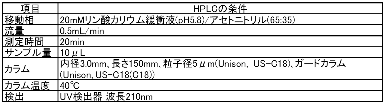
- a microneedle is punctured into the lumbar skin of a rat that has undergone hair removal under anesthesia, and after a predetermined application time has elapsed, the microneedle device is detached from the skin, and the remaining amount of lidocaine hydrochloride on the needle and the surface of the skin remain.
- the amount of intradermal transfer was measured by high performance liquid chromatography (HPLC), and the intradermal transfer rate was calculated.
- the skin surface was marked with a width of 20 mm and extended to 25 mm. After puncturing under the conditions shown in Table 3, the microneedle device was fixed to the skin with a tape (Johnson & Johnson, Dermicel) and applied as it was for a predetermined time.
- a tape Johnson & Johnson, Dermicel
- microneedle is peeled from the skin, and a cotton ball previously weighed is impregnated with phosphate buffered saline (PBS), and the administration site is wiped three times with the cotton ball, and further dried. Wipe once.
- PBS phosphate buffered saline
- the remaining amount of needle, the remaining amount of skin surface, the remaining amount of skin surface, and the amount of intradermal transfer are calculated from the measured value of lidocaine hydrochloride concentration of skin extract, and the remaining amount of needle, skin
- Each ratio with respect to the total of the remaining amount of the surface and the amount transferred into the skin was calculated as the remaining amount of needle, the remaining amount of the skin surface, and the transferred rate within the skin.
- Table 2 shows the needle residual ratio, the skin surface residual ratio, and the intradermal transfer rate of lidocaine hydrochloride in each Example and Comparative Example together with the test conditions.
- Examples 1 to 6 and Comparative Examples 1 and 2 are compared, Examples 1 to 6 having an aspect ratio of 2.1 or more are comparative examples having an aspect ratio of less than 2.1. It was confirmed that the intradermal transfer rate of the drug was higher than that of 1 and 2.
- Examples 5 and 6 when the aspect ratio is the same, the case where the drug is applied only to the tip region of the microneedle (Examples 5 and 6) is the whole. It was confirmed that the intradermal transfer rate was higher than in the case of being applied to (Examples 3 and 4).
- the microneedle 61 may be formed with a recess 62 for holding a drug.
- coated to a root part can be decreased, it becomes possible to administer a chemical
- the microneedle 71 may be formed with a step 72 so that the top side is thin.
- the amount of the drug held on the surface on the top side of the step 72 of the microneedle 71 can be increased, and the amount of the drug held at the root portion can be reduced, so that the drug is efficiently administered. It becomes possible.
- the microneedle 81 may be formed with a changing portion 82 that changes so that the inclination angle ⁇ with respect to the base 83 on the top side becomes smaller than that on the base side.
- the amount of drug held on the top side surface of the microneedle 81 can be increased and the amount of drug held at the root portion can be reduced, so that the drug can be efficiently administered. It becomes.
- the step since the step is not formed, it becomes easy to puncture the microneedle 81 to the vicinity of the root, and the drug can be efficiently administered.
- the inclination angle of the surface of the microneedle with respect to the base body may be formed so as to gradually decrease toward the top side. In this way, the surface of the microneedle becomes smooth, it becomes easier to puncture the microneedle, and the drug can be administered efficiently.
- microneedle device 20 61, 71, 81 microneedles, 21 top, 22 Bottom, 30, 83 substrate, 40 drugs, 83 Substrate.
Landscapes
- Health & Medical Sciences (AREA)
- Engineering & Computer Science (AREA)
- Dermatology (AREA)
- Life Sciences & Earth Sciences (AREA)
- Veterinary Medicine (AREA)
- Public Health (AREA)
- General Health & Medical Sciences (AREA)
- Animal Behavior & Ethology (AREA)
- Biomedical Technology (AREA)
- Hematology (AREA)
- Heart & Thoracic Surgery (AREA)
- Anesthesiology (AREA)
- Medical Informatics (AREA)
- Ceramic Engineering (AREA)
- Structural Engineering (AREA)
- Mechanical Engineering (AREA)
- Chemical & Material Sciences (AREA)
- Medicinal Chemistry (AREA)
- Pharmacology & Pharmacy (AREA)
- Epidemiology (AREA)
- Media Introduction/Drainage Providing Device (AREA)
Abstract
Description
(実施例1、実施例2)
(実施例3、実施例4)
(実施例5、実施例6)
(比較例1、比較例2)
[評価試験]
[薬剤の送達性の測定]
[試験結果]

20,61,71,81 マイクロニードル、
21 頂部、
22 底面、
30、83 基体、
40 薬剤、
83 基体。
Claims (3)
- 基体と、
前記基体上に形成されて皮膚を穿刺可能な突起であるマイクロニードルと、
前記マイクロニードルに塗布される薬剤と、
を有し、前記マイクロニードルの底面の最大幅に対する高さの比率であるアスペクト比が2.1以上であるマイクロニードルデバイス。 - 前記マイクロニードルの塗布される薬剤は、前記マイクロニードルの高さ方向において、前記マイクロニードルの頂部から高さの50%の範囲内に配置される請求項1に記載のマイクロニードルデバイス。
- 前記アスペクト比は、5以下である請求項1または2に記載のマイクロニードルデバイス。
Priority Applications (3)
| Application Number | Priority Date | Filing Date | Title |
|---|---|---|---|
| JP2016561538A JPWO2016084701A1 (ja) | 2014-11-28 | 2015-11-19 | マイクロニードルデバイス |
| EP15863705.8A EP3225276A4 (en) | 2014-11-28 | 2015-11-19 | Microneedle device |
| US15/606,831 US20170258712A1 (en) | 2014-11-28 | 2017-05-26 | Microneedle device |
Applications Claiming Priority (2)
| Application Number | Priority Date | Filing Date | Title |
|---|---|---|---|
| JP2014241676 | 2014-11-28 | ||
| JP2014-241676 | 2014-11-28 |
Related Child Applications (1)
| Application Number | Title | Priority Date | Filing Date |
|---|---|---|---|
| US15/606,831 Continuation US20170258712A1 (en) | 2014-11-28 | 2017-05-26 | Microneedle device |
Publications (1)
| Publication Number | Publication Date |
|---|---|
| WO2016084701A1 true WO2016084701A1 (ja) | 2016-06-02 |
Family
ID=56074268
Family Applications (1)
| Application Number | Title | Priority Date | Filing Date |
|---|---|---|---|
| PCT/JP2015/082552 Ceased WO2016084701A1 (ja) | 2014-11-28 | 2015-11-19 | マイクロニードルデバイス |
Country Status (4)
| Country | Link |
|---|---|
| US (1) | US20170258712A1 (ja) |
| EP (1) | EP3225276A4 (ja) |
| JP (1) | JPWO2016084701A1 (ja) |
| WO (1) | WO2016084701A1 (ja) |
Cited By (10)
| Publication number | Priority date | Publication date | Assignee | Title |
|---|---|---|---|---|
| KR20180009495A (ko) * | 2016-07-19 | 2018-01-29 | 부산대학교 산학협력단 | 마이크로니들, 이의 제조 방법, 및 이를 포함하는 패치 |
| KR20180009729A (ko) * | 2017-09-29 | 2018-01-29 | 부산대학교 산학협력단 | 마이크로니들, 이의 제조 방법, 및 이를 포함하는 패치 |
| WO2018062114A1 (ja) * | 2016-09-30 | 2018-04-05 | ニチバン株式会社 | マイクロニードルアレイの薬剤担持方法及び薬剤担持装置 |
| WO2018124290A1 (ja) * | 2016-12-28 | 2018-07-05 | コスメディ製薬株式会社 | 薬剤を塗布したマイクロニードルアレイ |
| KR20190047805A (ko) * | 2017-10-30 | 2019-05-09 | 장은주 | 생체흡수 및 생체분해 소재의 주입기 |
| KR20190088340A (ko) * | 2018-01-18 | 2019-07-26 | 부산대학교 산학협력단 | 이식형 마이크로니들 및 이의 제조 방법 |
| WO2019245345A1 (ko) * | 2018-06-22 | 2019-12-26 | 주식회사 에스엔비아 | 마이크로니들 |
| CN111870806A (zh) * | 2020-07-22 | 2020-11-03 | 南方科技大学 | 一种磁控微针机器人及其制备方法、使用方法和应用 |
| KR20210093188A (ko) * | 2020-01-17 | 2021-07-27 | 주식회사 쿼드메디슨 | 마이크로 니들 및 이의 제조 방법 |
| WO2025154786A1 (ja) * | 2024-01-18 | 2025-07-24 | コスメディ製薬株式会社 | マイクロニードルアレイ |
Families Citing this family (6)
| Publication number | Priority date | Publication date | Assignee | Title |
|---|---|---|---|---|
| CN108742718B (zh) * | 2018-03-23 | 2021-04-16 | 苏州德锐特成像技术有限公司 | 一种可快速溶胀的自粘附微针贴片及其制备方法 |
| CN108478520A (zh) * | 2018-04-18 | 2018-09-04 | 北京化工大学 | 一种可准确控制载药量的涂层微针阵列及其制备方法 |
| TWI687247B (zh) * | 2019-05-15 | 2020-03-11 | 微邦科技股份有限公司 | 微針結構及其生物可降解微針 |
| WO2022197452A2 (en) | 2021-03-03 | 2022-09-22 | Washington State University | Microneedle array with an interlocking feature |
| WO2023042889A1 (ja) * | 2021-09-15 | 2023-03-23 | コスメディ製薬株式会社 | 薬剤を塗布したマイクロニードルアレイ |
| NL2036831B1 (en) * | 2024-01-18 | 2025-07-28 | Mylife Tech B V | Microneedle device, patch, applicator and method |
Citations (3)
| Publication number | Priority date | Publication date | Assignee | Title |
|---|---|---|---|---|
| US20110223542A1 (en) * | 2008-02-07 | 2011-09-15 | The University Of Queensland | Patch production |
| JP2014514022A (ja) * | 2011-03-07 | 2014-06-19 | スリーエム イノベイティブ プロパティズ カンパニー | マイクロニードルデバイス及び方法 |
| WO2014126052A1 (ja) * | 2013-02-14 | 2014-08-21 | コスメディ製薬株式会社 | 薬物保持マイクロニードルアレイ及びその製造方法 |
Family Cites Families (8)
| Publication number | Priority date | Publication date | Assignee | Title |
|---|---|---|---|---|
| US6663820B2 (en) * | 2001-03-14 | 2003-12-16 | The Procter & Gamble Company | Method of manufacturing microneedle structures using soft lithography and photolithography |
| US20080262416A1 (en) * | 2005-11-18 | 2008-10-23 | Duan Daniel C | Microneedle Arrays and Methods of Preparing Same |
| WO2007112309A2 (en) * | 2006-03-24 | 2007-10-04 | 3M Innovative Properties Company | Process for making microneedles, microneedle arrays, masters, and replication tools |
| JP5297595B2 (ja) * | 2007-03-20 | 2013-09-25 | 凸版印刷株式会社 | 針状体および針状体製造方法 |
| CA2815811A1 (en) * | 2010-10-25 | 2012-05-03 | Medrx Co., Ltd. | Microneedle |
| MX344881B (es) * | 2010-12-02 | 2017-01-11 | 3M Innovative Properties Co | Microagujas de polimero cristalino liquido. |
| WO2013053022A1 (en) * | 2011-10-12 | 2013-04-18 | The University Of Queensland | Delivery device |
| JP2013248299A (ja) * | 2012-06-01 | 2013-12-12 | Dainippon Printing Co Ltd | マイクロニードルデバイス |
-
2015
- 2015-11-19 EP EP15863705.8A patent/EP3225276A4/en not_active Withdrawn
- 2015-11-19 JP JP2016561538A patent/JPWO2016084701A1/ja active Pending
- 2015-11-19 WO PCT/JP2015/082552 patent/WO2016084701A1/ja not_active Ceased
-
2017
- 2017-05-26 US US15/606,831 patent/US20170258712A1/en not_active Abandoned
Patent Citations (3)
| Publication number | Priority date | Publication date | Assignee | Title |
|---|---|---|---|---|
| US20110223542A1 (en) * | 2008-02-07 | 2011-09-15 | The University Of Queensland | Patch production |
| JP2014514022A (ja) * | 2011-03-07 | 2014-06-19 | スリーエム イノベイティブ プロパティズ カンパニー | マイクロニードルデバイス及び方法 |
| WO2014126052A1 (ja) * | 2013-02-14 | 2014-08-21 | コスメディ製薬株式会社 | 薬物保持マイクロニードルアレイ及びその製造方法 |
Cited By (23)
| Publication number | Priority date | Publication date | Assignee | Title |
|---|---|---|---|---|
| KR101891398B1 (ko) * | 2016-07-19 | 2018-08-23 | 부산대학교 산학협력단 | 마이크로니들, 이의 제조 방법, 및 이를 포함하는 패치 |
| KR20180009495A (ko) * | 2016-07-19 | 2018-01-29 | 부산대학교 산학협력단 | 마이크로니들, 이의 제조 방법, 및 이를 포함하는 패치 |
| WO2018062114A1 (ja) * | 2016-09-30 | 2018-04-05 | ニチバン株式会社 | マイクロニードルアレイの薬剤担持方法及び薬剤担持装置 |
| JPWO2018062114A1 (ja) * | 2016-09-30 | 2019-07-11 | ニチバン株式会社 | マイクロニードルアレイの薬剤担持方法及び薬剤担持装置 |
| CN110035792A (zh) * | 2016-12-28 | 2019-07-19 | 考司美德制药株式会社 | 涂布含药成分的微针制剂 |
| JP2018108375A (ja) * | 2016-12-28 | 2018-07-12 | コスメディ製薬株式会社 | 薬剤を塗布したマイクロニードルアレイ |
| WO2018124290A1 (ja) * | 2016-12-28 | 2018-07-05 | コスメディ製薬株式会社 | 薬剤を塗布したマイクロニードルアレイ |
| JP7509393B2 (ja) | 2016-12-28 | 2024-07-02 | コスメディ製薬株式会社 | 薬剤を塗布したマイクロニードルアレイ |
| AU2017388969B2 (en) * | 2016-12-28 | 2023-04-27 | Cosmed Pharmaceutical Co., Ltd. | Microneedle array coated with drug |
| KR102001305B1 (ko) * | 2017-09-29 | 2019-07-17 | 부산대학교 산학협력단 | 마이크로니들을 포함하는 패치 |
| KR20180009729A (ko) * | 2017-09-29 | 2018-01-29 | 부산대학교 산학협력단 | 마이크로니들, 이의 제조 방법, 및 이를 포함하는 패치 |
| KR20190047805A (ko) * | 2017-10-30 | 2019-05-09 | 장은주 | 생체흡수 및 생체분해 소재의 주입기 |
| KR102076394B1 (ko) * | 2017-10-30 | 2020-02-11 | 장은주 | 생체흡수 및 생체분해 소재의 주입기 |
| KR20190088340A (ko) * | 2018-01-18 | 2019-07-26 | 부산대학교 산학협력단 | 이식형 마이크로니들 및 이의 제조 방법 |
| KR102238033B1 (ko) * | 2018-01-18 | 2021-04-08 | 주식회사 에스엔비아 | 이식형 마이크로니들 및 이의 제조 방법 |
| US11938308B2 (en) | 2018-01-18 | 2024-03-26 | Snvia Co., Ltd. | Implantable microneedle and manufacturing method therefor |
| KR102092504B1 (ko) * | 2018-06-22 | 2020-03-24 | 주식회사 에스엔비아 | 마이크로니들 |
| KR20200000379A (ko) * | 2018-06-22 | 2020-01-02 | 주식회사 에스엔비아 | 마이크로니들 |
| WO2019245345A1 (ko) * | 2018-06-22 | 2019-12-26 | 주식회사 에스엔비아 | 마이크로니들 |
| KR20210093188A (ko) * | 2020-01-17 | 2021-07-27 | 주식회사 쿼드메디슨 | 마이크로 니들 및 이의 제조 방법 |
| KR102392782B1 (ko) * | 2020-01-17 | 2022-05-02 | 주식회사 쿼드메디슨 | 마이크로 니들 및 이의 제조 방법 |
| CN111870806A (zh) * | 2020-07-22 | 2020-11-03 | 南方科技大学 | 一种磁控微针机器人及其制备方法、使用方法和应用 |
| WO2025154786A1 (ja) * | 2024-01-18 | 2025-07-24 | コスメディ製薬株式会社 | マイクロニードルアレイ |
Also Published As
| Publication number | Publication date |
|---|---|
| US20170258712A1 (en) | 2017-09-14 |
| EP3225276A1 (en) | 2017-10-04 |
| JPWO2016084701A1 (ja) | 2017-09-07 |
| EP3225276A4 (en) | 2018-06-27 |
Similar Documents
| Publication | Publication Date | Title |
|---|---|---|
| WO2016084701A1 (ja) | マイクロニードルデバイス | |
| JP6612952B2 (ja) | 斜角開口部を有する中空マイクロニードル | |
| TWI643966B (zh) | 金屬微針 | |
| Chen et al. | Rapidly fabricated microneedle arrays using magnetorheological drawing lithography for transdermal drug delivery | |
| EP3021930B1 (en) | Hollow microneedle with beveled tip | |
| KR101323980B1 (ko) | 마이크로 니들 장치, 마이크로 니들 장치를 사용하는 방법 및 마이크로 니들 장치를 송출하는 방법 | |
| EP3021931B1 (en) | Hollow microneedle array article | |
| CN101330941A (zh) | 实心微针及其制造方法 | |
| CN1756575A (zh) | 具有组合构件的活性剂给药装置 | |
| JP2013529100A (ja) | 射出成形型マイクロニードルアレイ及びその製造方法 | |
| WO2015122838A1 (en) | Rapidly dissolvable microneedles with drug-impregnated tips | |
| CN106853271B (zh) | 微结构体的制造方法 | |
| JP6304431B2 (ja) | マイクロニードルデバイス | |
| WO2018155431A1 (ja) | マイクロニードルデバイス | |
| JP2015016160A (ja) | マイクロニードル | |
| JP2018015662A (ja) | マイクロニードルデバイス | |
| KR102127123B1 (ko) | 마이크로구조체 제조방법 | |
| JP2017094180A (ja) | マイクロニードルデバイス | |
| Kulkarni et al. | The microneedle patches: An innovative approach | |
| Bao et al. | A fabrication of whole-dissovable microneedles patch in larger area for transdermal drug delivery | |
| HK1218098B (zh) | 金属微针 |
Legal Events
| Date | Code | Title | Description |
|---|---|---|---|
| 121 | Ep: the epo has been informed by wipo that ep was designated in this application |
Ref document number: 15863705 Country of ref document: EP Kind code of ref document: A1 |
|
| ENP | Entry into the national phase |
Ref document number: 2016561538 Country of ref document: JP Kind code of ref document: A |
|
| NENP | Non-entry into the national phase |
Ref country code: DE |
|
| REEP | Request for entry into the european phase |
Ref document number: 2015863705 Country of ref document: EP |
|
| WWW | Wipo information: withdrawn in national office |
Ref document number: 2015863705 Country of ref document: EP |