WO2016084824A1 - 炭素繊維マット、プリフォーム、シート材料および成形品 - Google Patents
炭素繊維マット、プリフォーム、シート材料および成形品 Download PDFInfo
- Publication number
- WO2016084824A1 WO2016084824A1 PCT/JP2015/083000 JP2015083000W WO2016084824A1 WO 2016084824 A1 WO2016084824 A1 WO 2016084824A1 JP 2015083000 W JP2015083000 W JP 2015083000W WO 2016084824 A1 WO2016084824 A1 WO 2016084824A1
- Authority
- WO
- WIPO (PCT)
- Prior art keywords
- carbon fiber
- carbon fibers
- fiber mat
- discontinuous
- discontinuous carbon
- Prior art date
- Legal status (The legal status is an assumption and is not a legal conclusion. Google has not performed a legal analysis and makes no representation as to the accuracy of the status listed.)
- Ceased
Links
Images


Classifications
-
- B—PERFORMING OPERATIONS; TRANSPORTING
- B29—WORKING OF PLASTICS; WORKING OF SUBSTANCES IN A PLASTIC STATE IN GENERAL
- B29B—PREPARATION OR PRETREATMENT OF THE MATERIAL TO BE SHAPED; MAKING GRANULES OR PREFORMS; RECOVERY OF PLASTICS OR OTHER CONSTITUENTS OF WASTE MATERIAL CONTAINING PLASTICS
- B29B11/00—Making preforms
- B29B11/14—Making preforms characterised by structure or composition
- B29B11/16—Making preforms characterised by structure or composition comprising fillers or reinforcement
-
- B—PERFORMING OPERATIONS; TRANSPORTING
- B29—WORKING OF PLASTICS; WORKING OF SUBSTANCES IN A PLASTIC STATE IN GENERAL
- B29C—SHAPING OR JOINING OF PLASTICS; SHAPING OF MATERIAL IN A PLASTIC STATE, NOT OTHERWISE PROVIDED FOR; AFTER-TREATMENT OF THE SHAPED PRODUCTS, e.g. REPAIRING
- B29C70/00—Shaping composites, i.e. plastics material comprising reinforcements, fillers or preformed parts, e.g. inserts
- B29C70/04—Shaping composites, i.e. plastics material comprising reinforcements, fillers or preformed parts, e.g. inserts comprising reinforcements only, e.g. self-reinforcing plastics
- B29C70/06—Fibrous reinforcements only
- B29C70/10—Fibrous reinforcements only characterised by the structure of fibrous reinforcements, e.g. hollow fibres
- B29C70/12—Fibrous reinforcements only characterised by the structure of fibrous reinforcements, e.g. hollow fibres using fibres of short length, e.g. in the form of a mat
-
- D—TEXTILES; PAPER
- D04—BRAIDING; LACE-MAKING; KNITTING; TRIMMINGS; NON-WOVEN FABRICS
- D04H—MAKING TEXTILE FABRICS, e.g. FROM FIBRES OR FILAMENTARY MATERIAL; FABRICS MADE BY SUCH PROCESSES OR APPARATUS, e.g. FELTS, NON-WOVEN FABRICS; COTTON-WOOL; WADDING ; NON-WOVEN FABRICS FROM STAPLE FIBRES, FILAMENTS OR YARNS, BONDED WITH AT LEAST ONE WEB-LIKE MATERIAL DURING THEIR CONSOLIDATION
- D04H1/00—Non-woven fabrics formed wholly or mainly of staple fibres or like relatively short fibres
- D04H1/40—Non-woven fabrics formed wholly or mainly of staple fibres or like relatively short fibres from fleeces or layers composed of fibres without existing or potential cohesive properties
- D04H1/42—Non-woven fabrics formed wholly or mainly of staple fibres or like relatively short fibres from fleeces or layers composed of fibres without existing or potential cohesive properties characterised by the use of certain kinds of fibres insofar as this use has no preponderant influence on the consolidation of the fleece
- D04H1/4209—Inorganic fibres
- D04H1/4242—Carbon fibres
-
- D—TEXTILES; PAPER
- D04—BRAIDING; LACE-MAKING; KNITTING; TRIMMINGS; NON-WOVEN FABRICS
- D04H—MAKING TEXTILE FABRICS, e.g. FROM FIBRES OR FILAMENTARY MATERIAL; FABRICS MADE BY SUCH PROCESSES OR APPARATUS, e.g. FELTS, NON-WOVEN FABRICS; COTTON-WOOL; WADDING ; NON-WOVEN FABRICS FROM STAPLE FIBRES, FILAMENTS OR YARNS, BONDED WITH AT LEAST ONE WEB-LIKE MATERIAL DURING THEIR CONSOLIDATION
- D04H1/00—Non-woven fabrics formed wholly or mainly of staple fibres or like relatively short fibres
- D04H1/40—Non-woven fabrics formed wholly or mainly of staple fibres or like relatively short fibres from fleeces or layers composed of fibres without existing or potential cohesive properties
- D04H1/58—Non-woven fabrics formed wholly or mainly of staple fibres or like relatively short fibres from fleeces or layers composed of fibres without existing or potential cohesive properties by applying, incorporating or activating chemical or thermoplastic bonding agents, e.g. adhesives
-
- D—TEXTILES; PAPER
- D21—PAPER-MAKING; PRODUCTION OF CELLULOSE
- D21H—PULP COMPOSITIONS; PREPARATION THEREOF NOT COVERED BY SUBCLASSES D21C OR D21D; IMPREGNATING OR COATING OF PAPER; TREATMENT OF FINISHED PAPER NOT COVERED BY CLASS B31 OR SUBCLASS D21G; PAPER NOT OTHERWISE PROVIDED FOR
- D21H13/00—Pulp or paper, comprising synthetic cellulose or non-cellulose fibres or web-forming material
- D21H13/36—Inorganic fibres or flakes
- D21H13/46—Non-siliceous fibres, e.g. from metal oxides
- D21H13/50—Carbon fibres
-
- D—TEXTILES; PAPER
- D21—PAPER-MAKING; PRODUCTION OF CELLULOSE
- D21H—PULP COMPOSITIONS; PREPARATION THEREOF NOT COVERED BY SUBCLASSES D21C OR D21D; IMPREGNATING OR COATING OF PAPER; TREATMENT OF FINISHED PAPER NOT COVERED BY CLASS B31 OR SUBCLASS D21G; PAPER NOT OTHERWISE PROVIDED FOR
- D21H15/00—Pulp or paper, comprising fibres or web-forming material characterised by features other than their chemical constitution
- D21H15/02—Pulp or paper, comprising fibres or web-forming material characterised by features other than their chemical constitution characterised by configuration
- D21H15/06—Long fibres, i.e. fibres exceeding the upper length limit of conventional paper-making fibres; Filaments
-
- D—TEXTILES; PAPER
- D21—PAPER-MAKING; PRODUCTION OF CELLULOSE
- D21H—PULP COMPOSITIONS; PREPARATION THEREOF NOT COVERED BY SUBCLASSES D21C OR D21D; IMPREGNATING OR COATING OF PAPER; TREATMENT OF FINISHED PAPER NOT COVERED BY CLASS B31 OR SUBCLASS D21G; PAPER NOT OTHERWISE PROVIDED FOR
- D21H21/00—Non-fibrous material added to the pulp, characterised by its function, form or properties; Paper-impregnating or coating material, characterised by its function, form or properties
- D21H21/50—Non-fibrous material added to the pulp, characterised by its function, form or properties; Paper-impregnating or coating material, characterised by its function, form or properties characterised by form
- D21H21/52—Additives of definite length or shape
-
- B—PERFORMING OPERATIONS; TRANSPORTING
- B29—WORKING OF PLASTICS; WORKING OF SUBSTANCES IN A PLASTIC STATE IN GENERAL
- B29K—INDEXING SCHEME ASSOCIATED WITH SUBCLASSES B29B, B29C OR B29D, RELATING TO MOULDING MATERIALS OR TO MATERIALS FOR MOULDS, REINFORCEMENTS, FILLERS OR PREFORMED PARTS, e.g. INSERTS
- B29K2105/00—Condition, form or state of moulded material or of the material to be shaped
- B29K2105/06—Condition, form or state of moulded material or of the material to be shaped containing reinforcements, fillers or inserts
- B29K2105/12—Condition, form or state of moulded material or of the material to be shaped containing reinforcements, fillers or inserts of short lengths, e.g. chopped filaments, staple fibres or bristles
-
- B—PERFORMING OPERATIONS; TRANSPORTING
- B29—WORKING OF PLASTICS; WORKING OF SUBSTANCES IN A PLASTIC STATE IN GENERAL
- B29K—INDEXING SCHEME ASSOCIATED WITH SUBCLASSES B29B, B29C OR B29D, RELATING TO MOULDING MATERIALS OR TO MATERIALS FOR MOULDS, REINFORCEMENTS, FILLERS OR PREFORMED PARTS, e.g. INSERTS
- B29K2307/00—Use of elements other than metals as reinforcement
- B29K2307/04—Carbon
Definitions
- the present invention relates to a carbon fiber mat capable of obtaining a molded article having excellent mechanical properties and excellent formability. Specifically, discontinuous carbon fibers are dispersed in a single yarn, the orientation direction of the discontinuous carbon fibers is random, and the number average fiber length (L n ) of the carbon fibers is 1.5 mm or more and 15 mm or less, The present invention relates to a carbon fiber mat having a specific fiber length distribution.
- thermoplastic resin As the application of CFRP in the industrial field progresses, the application of thermoplastic resin to a matrix with a fast molding process cycle and excellent productivity is being actively researched.
- a sheet material using continuous fibers has high mechanical properties, but it is difficult to form a complex shape, and applicable products are limited.
- the injection molding material can produce a molded product having a complicated shape in a short time, but its mechanical properties are not sufficient, and it has been difficult to apply it to a structural member. From these backgrounds, development of a thermoplastic CFRP having high mechanical properties and capable of forming a complicated shape is desired.
- Patent Document 1 discloses a molded article made of a random mat in which a carbon fiber chopped strand is partially opened and a carbon fiber bundle and a carbon fiber single yarn are mixed. A manufacturing method is disclosed.
- Patent Document 2 discloses a prepreg in which carbon fibers are dispersed in a single yarn and are made of a randomly oriented carbon fiber mat and a resin, and the carbon fiber constituting the fiber has a wide fiber length distribution.
- the problem due to the large flow as described above does not occur, and a molded product having a certain degree of complex system such as a drawing can be obtained while exhibiting high mechanical characteristics. In some cases, the mechanical properties could not be sufficiently exhibited.
- An object of the present invention is to provide a carbon fiber mat, a preform and a sheet material for obtaining a molded product having excellent mechanical properties and a complicated shape.
- this invention consists of the following structures.
- Discontinuous carbon fibers are dispersed in the form of single yarn, the orientation direction of the single yarn of the discontinuous carbon fiber is random, the number average fiber length (L n ) is 1.5 mm or more and 15 mm or less, and the center fiber
- the carbon fiber mat wherein the number ratio (Pa) of single yarns of discontinuous carbon fibers in the range of ⁇ 20% of the length (L c ) is 40% or more and 99% or less.
- a preform comprising the carbon fiber mat according to any one of (1) to (5) and a thermoplastic resin.
- a sheet material obtained by heating and pressurizing the preform according to (6).
- a molded product obtained by heating and pressurizing the preform according to (6) or the sheet material according to (7).
- the carbon fiber mat of the present invention can obtain a molded product having isotropically excellent mechanical properties without being greatly restricted by the lamination angle when the prepreg is laminated.
- shape shaping such as drawing can be performed, and the obtained complex system shape also exhibits excellent mechanical properties.
- the sheet material can be suitably used for parts / members used for automobiles, electric / electronic parts, home appliances, airplanes, travel bags or daily necessities.
- discontinuous carbon fibers are dispersed in a single yarn shape, the orientation direction of the discontinuous carbon fibers is random, and the number average fiber length (L n ) is 1.5 mm or more and 15 mm or less,
- the number ratio (Pa) of discontinuous carbon fibers in the range of ⁇ 20% of the central fiber length (L c ) is 40% or more and 99% or less.
- the carbon fiber mat of the present invention has a form in which single yarns of discontinuous carbon fibers are dispersed in a planar shape, and examples thereof include a papermaking mat, a carding mat, and an airlaid mat.
- the discontinuous carbon fiber refers to a carbon fiber having a number average fiber length (L n ) in the range of 1.5 mm or more and 15 mm or less.
- the carbon fiber used for the discontinuous carbon fibers constituting the carbon fiber mat of the present invention it is preferable to use polyacrylonitrile (PAN) -based, rayon-based, lignin-based, pitch-based carbon fibers, or graphite fibers. Of these, it is more preferable to use PAN-based carbon fibers.
- PAN polyacrylonitrile
- These carbon fibers may be subjected to surface treatment. Examples of the surface treatment include a treatment with a sizing agent, a treatment with a binding agent, and an additive adhesion treatment.
- discontinuous carbon fibers constituting the carbon fiber mat of the present invention are dispersed in a single yarn shape.
- “dispersed in a single yarn” means that the discontinuous carbon fibers are bundled and do not exist in parallel for each single yarn, but exist separately for each single yarn.
- FIG. 2 can be exemplified as a state in which discontinuous carbon fibers are dispersed in a single yarn shape.
- the dispersion rate is preferably 90% or more. When the dispersion ratio is less than 90%, bundled discontinuous carbon fibers remain, and the strength of the carbon fiber mat may be reduced.
- the molded product containing the carbon fiber mat having a dispersion rate of less than 90% is that the area of the interface between the discontinuous carbon fibers and the matrix resin is reduced, the impregnation of the matrix resin is insufficient, and voids are generated.
- the mechanical properties may be reduced. From this point of view, the dispersive state of the discontinuous carbon fibers is more preferably 96% or more.
- the dispersion rate of the single yarn of the discontinuous carbon fiber is the two-dimensional contact angle formed by the single yarn of the discontinuous carbon fiber and the single yarn of another discontinuous carbon fiber in contact with the discontinuous carbon fiber. It is the ratio of the number of single yarns of discontinuous carbon fibers that are 1 ° or more when measured on the acute angle side from 0 ° to 90 °.
- the dispersion rate of the single yarn of the discontinuous carbon fiber is expressed by the following formula.
- the two-dimensional contact angle is an angle formed by a discontinuous carbon fiber single yarn and another discontinuous carbon fiber single yarn in contact with the discontinuous carbon fiber single yarn on a projection plane parallel to the carbon fiber mat. And defined as the angle on the acute angle side of 0 ° or more and 90 ° or less among the angles formed by the contacting single yarns.
- 2 (a) and 2 (b) are schematic views showing an example of a dispersive state of single yarns of discontinuous carbon fibers constituting the carbon fiber mat used in the present invention (only a single yarn of discontinuous carbon fibers is schematically shown). And is a schematic view when observed from the surface direction (FIG. 2 (a)) and the thickness direction (FIG. 2 (b)) of the carbon fiber mat.
- 2 (a) and 2 (b) 6, 7, 8, 9, 10 and 11 are single yarns of individual discontinuous carbon fibers.
- a single yarn 6 (hereinafter, simply referred to as a single yarn 6; the same applies to other yarns) of discontinuous carbon fibers in FIGS. 2 (a) and 2 (b).
- the single yarn 6 is observed crossing the single yarns 7 to 11 in FIG. 2 (a), but the single yarn 6 is not in contact with the single yarns 10 and 11 in FIG. 2 (b). . Therefore, the single yarn 6 to 9 are subject to the evaluation of the two-dimensional contact angle with respect to the single yarn 6 serving as a reference.
- the single yarn 6 and the single yarn 7, the single yarn 6 and the single yarn 8, and the single yarn 6 and the single yarn 6 The angles formed by the yarns 9 are measured.
- the two-dimensional contact angle formed by the single yarn 6 and the single yarn 7 is an angle ⁇ on the acute angle side that is 0 ° or more and 90 ° or less among two angles formed by the single yarn 6 and the single yarn 7.
- n and N for optically calculating the dispersion ratio, only the image in the surface direction of the carbon fiber mat corresponding to FIG. 2A is used, and within the image (that is, within the projection surface of the carbon fiber mat). In the case of crossing with the single yarn 6, the same evaluation is performed on the single yarns 7 to 11 to obtain an approximate value, and this may be used as the dispersion rate.
- the part for measuring the two-dimensional contact angle of the single yarn of the discontinuous carbon fiber constituting the carbon fiber mat, preform or sheet material but avoid the end of the carbon fiber mat, and as close to the center as possible. Therefore, it is preferable to measure using a portion where there is no change in thickness.
- the method for measuring the two-dimensional contact angle of the single yarn of the discontinuous carbon fiber constituting the carbon fiber mat or sheet material is not limited.
- the discontinuous carbon fiber from the surface of the carbon fiber mat or sheet material is not limited.
- the method of observing the contact angle of the single yarn can be exemplified. In this case, it is preferable to polish the surface to expose the fibers because it becomes easier to observe single yarns of discontinuous carbon fibers.
- the method of slicing a carbon fiber mat or sheet material thinly and observing the contact angle of the single yarn of discontinuous carbon fiber using transmitted light can be illustrated.
- a method of taking an orientation image of single fibers of discontinuous carbon fibers by observing a carbon fiber mat or sheet material by X-ray CT transmission can be exemplified.
- the tracer fiber is mixed with the single yarn of the discontinuous carbon fiber, or the tracer chemical is applied to the single yarn of the discontinuous carbon fiber. It is preferable because it becomes easier to observe single yarns of discontinuous carbon fibers.
- the orientation direction of the single yarns of the discontinuous carbon fibers constituting the carbon fiber mat of the present invention is random from the viewpoint of isotropic mechanical properties.
- the orientation direction of the single yarn of the discontinuous carbon fiber being random means that the orientation direction of the single yarn of the discontinuous carbon fiber is not regular.
- an index indicating the aspect of the orientation direction of the discontinuous carbon fibers there is a two-dimensional orientation angle frequency distribution described later. As will be described in detail later, in the two-dimensional orientation angle frequency distribution, the orientation direction is divided into six angles in the range of 0 ° to less than 180 °, and the number of single fibers whose orientation directions are in the range of the divided angles is relative.
- the relative frequency preferably has a maximum value of less than 0.25 and a minimum value of 0.09 or more.
- the maximum value of the relative frequency is 0.25 or more, or the minimum value is less than 0.09, the winding property of the carbon fiber mat is lowered, which may lead to a decrease in production efficiency.
- a preform including such a carbon fiber mat or a sheet material may have low moldability, and the homogeneity of mechanical properties of the molded product may be reduced.
- the maximum value and the minimum value of the relative frequency of the two-dimensional orientation angle distribution of the single yarn of the discontinuous carbon fibers constituting the carbon fiber mat of the present invention can be obtained by the following method. If the number of single yarns of discontinuous carbon fibers selected at random is 400 or more, the maximum value and the minimum value of the relative frequency in increments of 30 ° in the two-dimensional orientation angle frequency distribution of the single yarns of discontinuous carbon fibers are: Each is a constant value.
- the portion for measuring the maximum value and the minimum value of the relative frequency in increments of 30 ° in the two-dimensional orientation angle frequency distribution of the discontinuous carbon fiber but avoid the edge of the sheet material, as close to the center as possible, It is preferable to measure using a portion where there is no change in thickness.
- the relative frequencies in increments of 30 ° in the two-dimensional orientation angle frequency distribution of the discontinuous carbon fiber single yarn are all 0.17, the discontinuous carbon fiber single yarn orientation constituting the carbon fiber mat is completely random. It means that there is.
- the two-dimensional orientation angle ⁇ i is an angle between 0 ° and less than 180 ° by measuring an angle in a counterclockwise direction with respect to one arbitrarily set reference line.
- the relative frequency in increments of 30 ° of this orientation angle ⁇ i was determined by the following equation.
- the method of observing the orientation of the single yarn of discontinuous carbon fibers from the surface of the carbon fiber mat or sheet material can be exemplified.
- the method of slicing a carbon fiber mat or sheet material thinly, and observing the orientation of the single yarn of a discontinuous carbon fiber using transmitted light can be illustrated.
- a method of taking an orientation image of single fibers of discontinuous carbon fibers by observing a carbon fiber mat or sheet material by X-ray CT transmission can be exemplified.
- the tracer fiber is mixed with the single yarn of the discontinuous carbon fiber, or the tracer chemical is applied to the single yarn of the discontinuous carbon fiber. It is preferable because it becomes easier to observe single yarns of discontinuous carbon fibers.
- the number average fiber length (L n ) of single yarns of discontinuous carbon fibers constituting the carbon fiber mat of the present invention is 1.5 mm or more and 15 mm or less.
- the number average fiber length (L n ) is less than 1.5 mm, the reinforcing effect by the carbon fibers is low, and when such a carbon fiber mat is used, the mechanical properties of the molded product may be low.
- the number average fiber length (L n ) exceeds 15 mm, it is obtained by laminating a preform obtained by combining a carbon fiber mat with a thermoplastic resin or by heating / pressing the preform or the preform.
- the thickness expansion becomes large, and the handleability may be reduced. Further, when the number average fiber length (L n ) exceeds 15 mm, the dispersibility of the single yarn of the discontinuous carbon fiber becomes a bundle, and when such a carbon fiber mat is used, In some cases, the molded product contains voids, fiber bending, entanglement, and the like are likely to occur, and the mechanical properties and impact resistance of the molded product may decrease.
- the number average fiber length (L n ) of single yarns of discontinuous carbon fibers constituting the carbon fiber mat of the present invention is 2.5 mm or more and 10 mm or less.
- the number average fiber length (L n ) is 2.5 mm or more, the reinforcing effect by carbon fibers is higher, and a molded article having higher mechanical properties can be obtained by using such a carbon fiber mat.
- the number average fiber length (L n ) is 10 mm or less, the carbon fiber mat is obtained by laminating a preform obtained in combination with a thermoplastic resin, or obtained by heating / pressing the preform or the preform. In the process of forming the sheet material to be formed, the thickness expansion is reduced, and therefore the handleability is further improved.
- the variation coefficient (CV) of the fiber length of the single yarn of the discontinuous carbon fibers constituting the carbon fiber mat of the present invention is preferably 0.1% or more and 55% or less.
- the coefficient of variation (CV) of the fiber length is an index indicating the variation in the fiber length of the single yarn of the discontinuous carbon fibers constituting the carbon fiber mat, and is obtained by measuring the fiber length of a specified number of carbon fiber single yarns.
- the fiber length standard deviation ( ⁇ ) is divided by the number average fiber length (L n ).
- the number average fiber length (L n ) and coefficient of variation (CV) of the fiber length of the discontinuous carbon fibers in the carbon fiber mat, preform or sheet material of the present invention can be measured by the following methods. . Cut out a part of the carbon fiber mat, preform or sheet material, dissolve the binder and matrix sufficiently with a solvent that dissolves the binder and matrix, and then separate the single yarns of discontinuous carbon fibers by a known operation such as filtration. . If there is no solvent to dissolve the binder and matrix, a portion of the carbon fiber mat, preform or sheet material is cut out and heated at a temperature of 500 ° C. for 30 minutes, and the binder and matrix are burned off to discontinuously discontinue the carbon fibers. Separate the yarn.
- the number average fiber length (L n ), the standard deviation ( ⁇ ) of the fiber length, and the coefficient of variation (CV) of the fiber length can be obtained from the following equations.
- Lc A value (unit: mm) located at the center when all measured fiber lengths (L 1 , L 2 , L 3 ,... L 400 ) are arranged in ascending order.
- the number ratio (Pa) of single fibers of discontinuous carbon fibers in the range of ⁇ 20% of the center fiber length (L c ) of single fibers of discontinuous carbon fibers is 40% or more and 99. % Or less is important.
- Pa is less than 40%, the moldability when molding a preform obtained by combining a carbon fiber mat with a thermoplastic resin and a sheet material obtained by heating / pressing it, and the mechanical properties of the resulting molded product May be low.
- various conditions are adopted so that all carbon fibers are cut to the same length in the step of cutting carbon fibers and no breakage of the carbon fibers occurs in the matting step. Therefore, production efficiency may be low.
- the number ratio (Pb) of discontinuous carbon fibers in the range of ⁇ 1 mm of the center fiber length (L c ) of the discontinuous carbon fibers is 50% or more and 99% or less. It is preferable that If Pb is 50% or more, the preform obtained by combining the carbon fiber mat with the thermoplastic resin and the sheet material obtained by heating / pressing the preform become more excellent. Moreover, since the mechanical characteristics of the molded article obtained from them become more excellent, it is preferable. Further, in order to make Pb higher than 99%, various conditions are employed so that all carbon fibers are cut to the same length in the step of cutting carbon fibers and no breakage of the carbon fibers occurs in the matting step. Therefore, production efficiency may be low.
- the number ratio (Pa) of carbon fibers in the range of ⁇ 20% of the center fiber length (L c ) of the single yarn of the discontinuous carbon fibers, and the carbon fibers in the range of ⁇ 1 mm of the center fiber length (L c ) the number ratio of (Pb), using the fiber length L i of the single yarn of discontinuous carbon fiber to be measured in determining said number average fiber length (L n), is calculated by the following equation.
- the preform of the present invention includes at least the carbon fiber mat of the present invention and a thermoplastic resin, and is in a state before being processed into a molded product. is there.
- stacked the preform of this invention is provided to a formation process directly or through a secondary processing process, and is processed into a molded article.
- the secondary processing step is not particularly limited, but a cutting step for cutting the molding material into a predetermined size and shape, a bonding step for improving the handleability of the preform by bonding the carbon fiber mat and the thermoplastic resin,
- a defoaming step of extracting air from the preform is not particularly limited, but a cutting step for cutting the molding material into a predetermined size and shape, a bonding step for improving the handleability of the preform by bonding the carbon fiber mat and the thermoplastic resin.
- An example is a defoaming step of extracting air from the preform.
- the laminated structure in the case where the preform of the present invention is used as a laminated body is not particularly limited, and a desired laminated structure can be selected from the viewpoints of mechanical properties, impact resistance, shaping properties, design properties, and the like.
- a desired laminated structure can be selected from the viewpoints of mechanical properties, impact resistance, shaping properties, design properties, and the like.
- the thermoplastic resin is sufficiently impregnated and molded products with excellent mechanical properties. Obtainable.
- the molded article which is excellent in surface appearance can be obtained by shape
- thermoplastic resin constituting the preform and sheet material in the present invention examples include, for example, polyolefin resins such as polyethylene (PE) resin and polypropylene (PP) resin, polyethylene terephthalate (PET) resin, polyamide (PA) resin, Examples thereof include polyphenylene sulfide (PPS) resin and the like, copolymer resins and modified resins thereof, and alloys.
- polypropylene resin is preferable from the viewpoint of light weight of the obtained molded product
- a polyamide resin is preferable from the viewpoint of rigidity.
- polyphenylene sulfide resin is preferably used.
- the preform of the present invention may contain a third sheet-shaped material in a range not impairing characteristics in addition to the carbon fiber mat (first sheet-shaped material) and the thermoplastic resin (second sheet-shaped material). it can.
- a third sheet-like material a sheet-like material using a thermoplastic resin as a matrix resin is preferable from the viewpoint of adhesiveness, and examples thereof include a thermoplastic UD prepreg, a compound sheet, and a thermoplastic foamed resin sheet.
- the sheet material of the present invention is obtained by heating the preform of the present invention, melting the thermoplastic resin, and then applying pressure to impregnate and integrate the thermoplastic resin into the carbon fiber mat.
- a manufacturing method of sheet material For example, the method of applying high temperature high pressure in a metal mold press and an autoclave is mentioned.
- Another example is a method in which a sheet material is fed into a pressure-bonding zone that can be subjected to a desired temperature and pressure using an apparatus such as a double belt press or a calender roll. In this way, a sheet material can be produced by operating a continuous or semi-continuous process.
- the preform or sheet material of the present invention can be molded by heating and pressing to obtain a molded product.
- press molding is exemplified.
- the type of press molding can be selected according to the shape of the molded product.
- press molding refers to a molded product by applying deformation such as bending, shearing, compression, etc. to a laminate of a preform or a sheet material using a processing machine and a die, a tool, or other molding jigs or auxiliary materials. Is the way to get.
- Examples of the forming form include drawing, deep drawing, flange, call gate, edge curling, stamping and the like.
- a metal mold is used from the viewpoint of energy consumption in equipment and molding process, simplification of jigs and auxiliary materials used, molding pressure, and flexibility of temperature. It is more preferable to use a die press method in which molding is performed.
- a preform or sheet material is placed in a mold in advance, pressed and heated together with mold clamping, and then the preform or sheet is cooled by mold cooling.
- Heat and cool method to obtain a molded product by cooling the material, or heating the preform or sheet material in advance to the melting temperature of the matrix resin or more, such as far infrared heater, heating plate, high temperature oven, dielectric heating, etc.
- Stamping which is a method of heating with an apparatus, placing the thermoplastic resin on the mold that will be the lower surface of the molding die in a state where the thermoplastic resin is melted and softened, then closing the die and clamping, and then pressurizing and cooling The law can be adopted.
- the basis weight of the carbon fiber mat of the present invention is preferably 10 g / m 2 or more and 50 g / m 2 or less.
- the strength is 10 g / m 2 or more, the strength of the carbon fiber mat is high, there is no problem such as tearing, and the handleability is more excellent.
- the preform or sheet material of the present invention can be thinned, and it follows the complex mold shape having ribs, bosses, deep drawing, standing walls, etc. An excellent molded product can be obtained.
- a preform or sheet material in which a thin layer of carbon fiber mats of 50 g / m 2 or less is laminated is formed between one layer of carbon fiber mats and carbon fiber mats disposed above and below at the time of molding. Since sliding occurs, wrinkles and twists are suppressed, and mechanical properties and appearance are excellent.
- a filler In the molded product of the present invention, a filler, a conductivity imparting material, a flame retardant, a pigment, a dye, a lubricant, a release agent, a compatibilizing agent, a dispersant, a crystal nucleating agent, a plasticizer, Add heat stabilizer, antioxidant, anti-coloring agent, UV absorber, fluidity modifier, foaming agent, antibacterial agent, vibration control agent, deodorant, slidability modifier, antistatic agent, etc. Also good.
- Carbon fiber (CF) Carbon fiber Spinning and firing were performed from a polymer containing polyacrylonitrile as a main component to obtain continuous carbon fiber having a total number of filaments of 12,000. Further, the continuous carbon fiber was subjected to electrolytic surface treatment and dried in heated air at 120 ° C. to obtain carbon fiber (CF-1). The characteristics of this carbon fiber (CF-1) were as follows.
- Binder (B-1) As the binder, an aqueous dispersion prepared by adjusting “Polyment” (registered trademark) SK-1000 manufactured by Nippon Shokubai Co., Ltd. to a solid content concentration of 1.6 wt% was used. Its physical properties are as follows.
- Carbon fiber mat 1 Carbon fiber (CF-1) was cut to 6 mm with a cartridge cutter to obtain a chopped fiber which is a discontinuous carbon fiber.
- the papermaking apparatus comprises an upper papermaking tank (capacity 50 liters) equipped with a stirrer with rotary blades and a lower water storage tank (capacity 10 liters), and a porous support is provided between the papermaking tank and the water tank. .
- a chopped fiber whose mass was adjusted so as to obtain a desired basis weight was put into a dispersion medium.
- the dispersion was stirred for 3 minutes by intermittent stirring where the forward rotation / reverse rotation of the stirrer was switched every 10 seconds to obtain a slurry in which discontinuous carbon fibers were dispersed.
- the slurry was sucked from the water storage layer, dehydrated through the porous support, and the binder (B-1) was added to obtain a carbon fiber mat made of discontinuous carbon fibers.
- the carbon fiber mat 1 was dried in a hot air dryer at 150 ° C. for 2 hours to obtain a carbon fiber mat 1 made of discontinuous carbon fibers having a basis weight of 100 g / m 2 .
- Carbon fiber mat 2 Carbon fiber mat made of discontinuous carbon fibers with a basis weight of 100 g / m 2 in the same manner as the carbon fiber mat 1 except that the forward rotation / reverse rotation of the stirrer is switched every 5 seconds and the dispersion ratio is intentionally increased. 2 was obtained.
- Carbon fiber mat 3 Carbon fiber mat 3 (CFM-3)] Except for switching the forward rotation / reverse rotation of the stirrer every 5 seconds and stirring the dispersion for 5 minutes to intentionally increase the dispersion rate, the same as the carbon fiber mat 1 made of discontinuous carbon fibers, A carbon fiber mat 3 made of discontinuous carbon fibers having a basis weight of 100 g / m 2 was obtained.
- Carbon fiber mat 4 A discontinuous carbon fiber having a basis weight of 100 g / m 2 is obtained in the same manner as the carbon fiber mat 1 made of discontinuous carbon fiber except that chopped fiber obtained by cutting carbon fiber (CF-1) into 3 mm with a cartridge cutter is used.
- a carbon fiber mat 4 consisting of [Carbon fiber mat 5 (CFM-5)] A discontinuous carbon fiber having a basis weight of 100 g / m 2 was obtained in the same manner as the carbon fiber mat 1 made of discontinuous carbon fiber except that chopped fiber obtained by cutting carbon fiber (CF-1) to 10 mm with a cartridge cutter was used.
- Carbon fiber mat 8 (CFM-8)] Using a chopped fiber with carbon fiber (CF-1) cut to 15 mm with a cartridge cutter, stir for 15 minutes with the agitator rotating forward, intentionally within ⁇ 20% of the center fiber length (L c ) A carbon fiber mat 8 made of discontinuous carbon fibers having a basis weight of 100 g / m 2 was obtained in the same manner as the carbon fiber mat 1 made of discontinuous carbon fibers, except that the number ratio of certain discontinuous carbon fibers was reduced.
- Carbon fiber mat 9 (CFM-9)] Using a chopped fiber in which carbon fiber (CF-1) is cut to 6 mm with a cartridge cutter, stir for 15 minutes with the agitator rotating forward, intentionally within ⁇ 20% of the center fiber length (L c ) A carbon fiber mat 9 made of discontinuous carbon fibers having a basis weight of 100 g / m 2 was obtained in the same manner as the carbon fiber mat 1 made of discontinuous carbon fibers, except that the number ratio of certain discontinuous carbon fibers was reduced.
- Carbon fiber mat 10 (CFM-10)] Using a chopped fiber with carbon fiber (CF-1) cut to 50 mm with a cartridge cutter, stir for 15 minutes with the agitator rotating forward, intentionally within ⁇ 20% of the center fiber length (L c ) A carbon fiber mat 10 made of discontinuous carbon fibers having a basis weight of 100 g / m 2 was obtained in the same manner as the carbon fiber mat 1 made of discontinuous carbon fibers, except that the number ratio of certain discontinuous carbon fibers was reduced.
- Carbon fiber mat 11 (CFM-11) Carbon made of discontinuous carbon fiber, except that carbon fiber (CF-1) was cut to 6 mm with a cartridge cutter and stirred for 30 seconds with the agitator rotating forward to intentionally reduce the dispersion rate.
- a carbon fiber mat 11 made of discontinuous carbon fibers having a basis weight of 100 g / m 2 was obtained in the same manner as the fiber mat 1.
- Carbon fiber mat 12 (CFM-12) A carbon fiber mat 12 made of discontinuous carbon fibers having a basis weight of 33 g / m 2 was obtained in the same manner as the carbon fiber mat 1 made of discontinuous carbon fibers, except that the basis weight of the carbon fiber mat was changed to 33 g / m 2. It was.
- thermoplastic resin film 1 A predetermined amount of polypropylene resin ("Prime Polypro” (registered trademark) J707G, manufactured by Prime Polymer Co., Ltd.) is placed on a stainless steel plate, and another stainless steel plate is stacked on top of it. Put a spacer of desired thickness.
- the pressing temperature was 220 ° C.
- the pressure was 1 MPa
- the pressure was maintained for 5 minutes to obtain a thermoplastic resin film 1 (TPF-1) having a basis weight of 120 g / m 2 .
- thermoplastic resin film 2 (TPF-2)
- Predetermined amount of polyamide resin manufactured by Toray Industries Co., Ltd., “Amilan” (registered trademark) CM1021T
- CM1021T a stainless steel plate
- a spacer of a thickness of was inserted.
- the pressing temperature was 250 ° C.
- the pressure was 1 MPa
- the pressure was maintained for 5 minutes to obtain a thermoplastic resin film 2 (TPF-2) having a basis weight of 150 g / m 2 .
- Carbon fiber reinforced thermoplastic resin sheet 1 A total of three carbon fiber mats 1 (CFM-1) and 2 thermoplastic resin sheets 2 (TPF-2) are placed on a stainless steel tool plate and pressed.
- the carbon fiber reinforced thermoplastic resin sheet material 1 (CFRP-1) was obtained by pressing at 220 ° C. and a pressure of 5 MPa for 5 minutes.
- the thickness of the sheet-like carbon fiber reinforced thermoplastic resin sheet 1 (CFRP-1) was adjusted to 0.33 mm by using a 0.33 mm spacer.
- Carbon fiber reinforced thermoplastic resin sheet 2 A total of five carbon fiber mats 12 (CFM-12) and two thermoplastic resin sheets 2 (TPF-2) are placed on a stainless steel tool plate and pressed.
- the carbon fiber reinforced thermoplastic resin sheet material 2 (CFRP-2) was obtained by pressing at 220 ° C. and a pressure of 5 MPa for 5 minutes.
- the thickness of the sheet-like carbon fiber reinforced thermoplastic resin sheet 2 (CFRP-2) was adjusted to 0.33 mm by using a 0.33 mm spacer.
- ⁇ Mold> (Mold 1) Mold for Molding A pair of opposed molds (FIG. 3) for obtaining the box-shaped product of FIG. 1, and a mold having the dimensions shown below was prepared.
- the dimensions of the lower mold (convex mold) and the upper mold (concave mold) are shown in FIGS.
- orientation angle ⁇ i the angle in the counterclockwise direction with respect to the reference straight line was measured, and the angle was 0 ° or more and less than 180 °.
- the relative frequency in increments of 30 ° of this orientation angle ⁇ i was determined by the following formula.
- test piece for measuring the two-dimensional orientation angle of the single yarn of the discontinuous carbon fibers constituting the carbon fiber mat or sheet material a portion where the thickness did not change was used as close to the center as possible.
- cut out a part of the carbon fiber mat or sheet material embed the cut specimen in an epoxy resin, and polish the embedded material to a depth at which the discontinuous carbon fiber single yarn is exposed. An observation test piece was prepared.
- An "Instron” (registered trademark) universal testing machine 4201 type (manufactured by Instron) is used as a testing machine, and a support span is set to a specimen thickness of 16 using a three-point bending test jig (indenter diameter 10 mm, fulcrum diameter 10 mm) The bending elastic modulus was measured by setting to double. The test was performed under the conditions that the moisture content of the test piece was 0.1% by mass or less, the ambient temperature was 23 ° C., and the humidity was 50% by mass.
- CV b s b / ⁇ b ⁇ 100 (unit:%).
- the length 62 ⁇ 1 mm, the width 12.7 ⁇ 0.15 mm, the notch angle 22.5 ° ⁇ 0.5 °, respectively A 25 ⁇ 0.05R Izod impact strength test piece was cut out in two directions of 0 ° and 90 ° directions when an arbitrary direction was set to 0 ° direction to produce a test piece.
- the test was performed under the conditions that the moisture content of the test piece was 0.1% by mass or less, the ambient temperature was 23 ° C., and the humidity was 50% by mass.
- Example 1 A preform in which a total of nine carbon fiber mats 1 (CFM-1) made of discontinuous carbon fibers and six thermoplastic resin sheets 1 (TPF-1) are superposed is used as a gold for press at room temperature.
- the mold temperature was raised to 220 ° C. in a state where the mold 1 was set and a pressure of 0.1 MPa was applied. Thereafter, press molding was performed at a pressure of 5 MPa for 5 minutes, and the molded product was obtained by naturally cooling to a room temperature of 25 ° C. while maintaining the pressure. At this time, the thickness of the molded product was adjusted to 1 mm by using a 1 mm spacer. After observing the surface appearance of the obtained molded product, the top plate was cut into a predetermined size and subjected to evaluation. The evaluation results are summarized in Table 1.
- Example 2 The procedure and method were the same as in Example 1 except that carbon fiber mat 2 (CFM-2) made of discontinuous carbon fibers was used instead of carbon fiber mat 1 (CFM-1) made of discontinuous carbon fibers. A molded product was obtained. The characteristics are summarized in Table 1.
- Example 3 The procedure and method were the same as in Example 1 except that carbon fiber mat 3 (CFM-3) made of discontinuous carbon fibers was used instead of carbon fiber mat 1 (CFM-1) made of discontinuous carbon fibers. A molded product was obtained. The characteristics are summarized in Table 1.
- Example 4 The procedure and method were the same as in Example 1 except that carbon fiber mat 4 (CFM-4) made of discontinuous carbon fibers was used instead of carbon fiber mat 1 (CFM-1) made of discontinuous carbon fibers. A molded product was obtained. The characteristics are summarized in Table 1.
- Example 5 The procedure and method were the same as in Example 1 except that carbon fiber mat 5 (CFM-5) made of discontinuous carbon fibers was used instead of carbon fiber mat 1 (CFM-1) made of discontinuous carbon fibers. A molded product was obtained. The characteristics are summarized in Table 1.
- Example 6 The procedure and method were the same as in Example 1 except that carbon fiber mat 6 (CFM-6) made of discontinuous carbon fibers was used instead of carbon fiber mat 1 (CFM-1) made of discontinuous carbon fibers. A molded product was obtained. The characteristics are summarized in Table 1.
- Example 7 The procedure and method were the same as in Example 1 except that carbon fiber mat 7 (CFM-7) made of discontinuous carbon fibers was used instead of carbon fiber mat 1 (CFM-1) made of discontinuous carbon fibers. A molded product was obtained. The characteristics are summarized in Table 1.
- Example 8 A preform in which a total of nine carbon fiber mats 1 (CFM-1) made of discontinuous carbon fibers and six thermoplastic resin sheets 2 (TPF-2) are superposed is used as a pressing metal at room temperature.
- the mold temperature was raised to 250 ° C. in a state where the mold 1 was set and a pressure of 0.1 MPa was applied. Thereafter, press molding was performed at a pressure of 5 MPa for 5 minutes, and the molded product was obtained by naturally cooling to a room temperature of 25 ° C. while maintaining the pressure. At this time, the thickness of the molded product was adjusted to 1 mm by using a 1 mm spacer. After observing the surface appearance of the obtained molded product, the top plate was cut into a predetermined size and subjected to evaluation. The evaluation results are summarized in Table 1.
- Example 9 Three carbon fiber reinforced thermoplastic resin sheets 1 (CFRP-1) are individually placed in an oven equipped with a far infrared heater, and it is confirmed that the temperature of the thermocouple installed on each sheet reaches 220 ° C. After that, three sheets were laminated in an oven to form a preform 1.
- CFRP-1 carbon fiber reinforced thermoplastic resin sheets 1
- the preheated preform 1 was placed in a press mold 1 preheated to 80 ° C., and press molded at a pressure of 10 MPa for 5 minutes to obtain a molded product.
- the thickness of the molded product was adjusted to 1 mm by using a 1 mm spacer.
- the top plate was cut into a predetermined size and subjected to evaluation. The evaluation results are summarized in Table 1.
- Example 10 A molded product was prepared by the same procedure and method as in Example 9 except that carbon fiber reinforced thermoplastic resin sheet 2 (CFRP-2) was used instead of carbon fiber reinforced thermoplastic resin sheet 1 (CFRP-1). Obtained. The characteristics are summarized in Table 1.
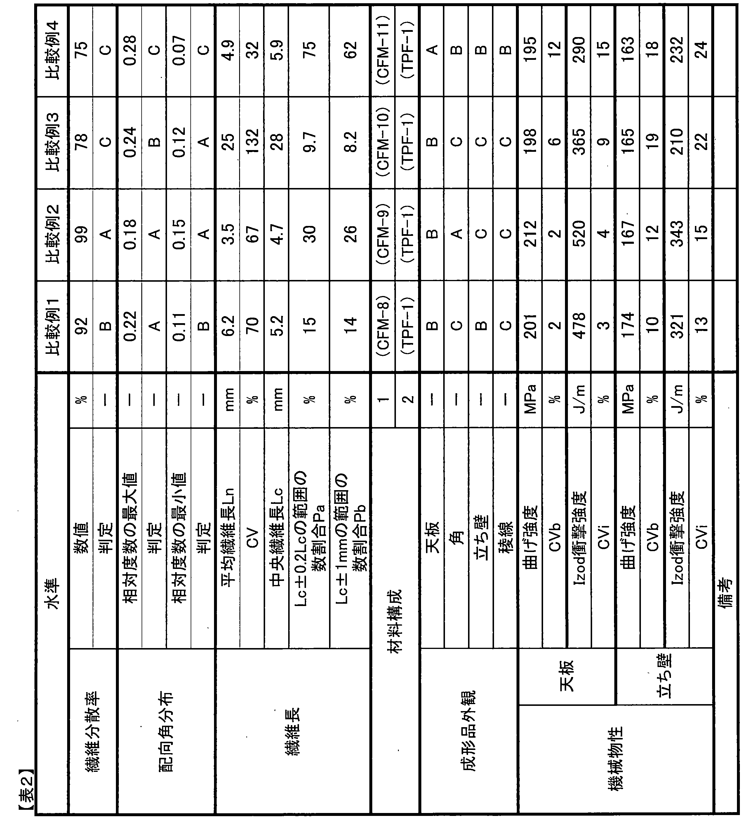
- Example 1 Comparative Example 1 The procedure and method were the same as in Example 1 except that carbon fiber mat 8 (CFM-8) made of discontinuous carbon fibers was used instead of carbon fiber mat 1 (CFM-1) made of discontinuous carbon fibers. A molded product was obtained. The characteristics are summarized in Table 2.
- Example 2 The procedure and method were the same as in Example 1 except that carbon fiber mat 9 (CFM-9) made of discontinuous carbon fibers was used instead of carbon fiber mat 1 (CFM-1) made of discontinuous carbon fibers. A molded product was obtained. The characteristics are summarized in Table 2.
- Example 3 The procedure and method were the same as in Example 1 except that carbon fiber mat 10 (CFM-10) made of discontinuous carbon fibers was used instead of carbon fiber mat 1 (CFM-1) made of discontinuous carbon fibers. A molded product was obtained. The characteristics are summarized in Table 2.
- Example 4 The procedure and method were the same as in Example 1 except that carbon fiber mat 11 (CFM-11) made of discontinuous carbon fibers was used instead of carbon fiber mat 1 (CFM-1) made of discontinuous carbon fibers. A molded product was obtained. The characteristics are summarized in Table 2.
- the discontinuous carbon fibers constituting the carbon fiber mat of the present invention are randomly dispersed in the form of a single yarn, and the number average fiber length (L n ) and the center fiber length (L c ) as defined in this specification.
- the number ratio (Pa) of the discontinuous carbon fibers in the range of ⁇ 20% of can be adjusted by adjusting so as to satisfy the specified value.
- the carbon fiber mat adjusted so that the coefficient of variation (CV) of the fiber length and the number ratio (Pb) of discontinuous carbon fibers in the range of ⁇ 1.0 mm of the center fiber length (L c ) satisfy the specified values.
- CV coefficient of variation
- Pb number ratio
- Comparative Examples 1 to 4 it was not possible to obtain molded products having excellent mechanical properties and shape shaping properties.
- the molded products of Comparative Examples 1 to 3 were inferior in mechanical properties and surface quality, and Comparative Example 4 was inferior in mechanical properties.
- Molded articles using the carbon fiber mat of the present invention exhibit high mechanical properties, shape shaping such as drawing is possible, and the obtained complex system also exhibits excellent mechanical properties, so it can be used in various applications. Can be deployed. Among them, it can be suitably used for automobile / aircraft parts, electrical / electronic product parts, and travel bags.
Landscapes
- Engineering & Computer Science (AREA)
- Textile Engineering (AREA)
- Chemical & Material Sciences (AREA)
- Mechanical Engineering (AREA)
- Inorganic Chemistry (AREA)
- Composite Materials (AREA)
- Reinforced Plastic Materials (AREA)
- Nonwoven Fabrics (AREA)
- Casting Or Compression Moulding Of Plastics Or The Like (AREA)
- Paper (AREA)
- Moulding By Coating Moulds (AREA)
Abstract
Description
(1)不連続炭素繊維が単糸状に分散し、前記不連続炭素繊維の単糸の配向方向がランダムであり、数平均繊維長(Ln)が1.5mm以上15mm以下であり、中央繊維長(Lc)の±20%の範囲にある不連続炭素繊維の単糸の数割合(Pa)が40%以上99%以下であることを、炭素繊維マット。
(2)前記不連続炭素繊維の単糸の繊維長の変動係数(CV)が0.1%以上55%以下である、(1)に記載の炭素繊維マット。
(3)前記不連続炭素繊維の単糸の数平均繊維長(Ln)が2.5mm以上10mm以下である、(1)から(2)のいずれかに記載の炭素繊維マット。
(4)前記不連続炭素繊維の単糸の中央繊維長(Lc)の±1mmの範囲にある、不連続炭素繊維の単糸の数割合(Pb)が50%以上99%以下である、(1)から(3)のいずれかに記載の炭素繊維マット。
(5)目付が10g/m2以上50g/m2以下である、(1)から(4)のいずれかに記載の炭素繊維マット。
(6)(1)から(5)のいずれかに記載の炭素繊維マットと熱可塑樹脂を含む、プリフォーム。
(7)(6)に記載のプリフォームを加熱・加圧して得られる、シート材料。
(8)(6)に記載のプリフォームまたは(7)に記載のシート材料を加熱・加圧して得られる、成形品。
・P:分散率
・n:接触角度が1°以上である不連続炭素繊維の単糸の総数
・N:接触角度を計測した不連続炭素繊維の単糸の総数
ここで、ある不連続炭素繊維の単糸が、複数の不連続炭素繊維と接触している場合には、n(接触角度が1°以上である不連続炭素繊維の単糸の総数)はそれぞれ合算し、N(不連続炭素繊維の単糸の総数)はのべ本数でカウントし400以上とする。
相対度数の最小値=NMIN/400
・αi:測定した配向角度(i=1、2、・・、400)
・N30:配向角度αiが0°以上30°未満の不連続炭素繊維の単糸の本数
・N60:配向角度αiが30°以上60°未満の不連続炭素繊維の単糸の本数
・N90:配向角度αiが60°以上90°未満の不連続炭素繊維の単糸の本数
・N120:配向角度αiが90°以上120°未満の不連続炭素繊維の単糸の本数
・N150:配向角度αiが120°以上150°未満の不連続炭素繊維の単糸の本数
・N180:配向角度αiが150°以上180°未満の不連続炭素繊維の単糸の本数
・NMAX:上記、N30~N180の中の最大値
・NMIN:上記、N30~N180の中の最小値
具体的に、炭素繊維マット、プリフォームまたはシート材料を構成する不連続炭素繊維の単糸二次元配向角度を測定する方法に制限はないが、例えば、炭素繊維マットまたはシート材料の表面から不連続炭素繊維の単糸の配向を観察する方法が例示できる。この場合、表面を研磨して不連続炭素繊維の単糸を露出させると、より不連続炭素繊維の単糸を観察しやすくなるため好ましい。また、炭素繊維マットまたはシート材料を薄くスライスし、透過光を利用して不連続炭素繊維の単糸の配向を観察する方法が例示できる。さらに、炭素繊維マットまたはシート材料をX線CT透過観察して不連続炭素繊維の単糸の配向画像を撮影する方法も例示できる。X線透過性の高い炭素繊維の場合には、不連続炭素繊維の単糸にトレーサ用の繊維を混合しておく、あるいは不連続炭素繊維の単糸にトレーサ用の薬剤を塗布しておくと、より不連続炭素繊維の単糸を観察しやすくなるため好ましい。
σ=(1/400・Σ(Li-Ln)2)(1/2)(単位:mm)
CV=σ/Ln×100(単位:%)
・Lc:測定した全ての繊維長(L1,L2,L3,・・・L400)を小さい順に並べたときに中央に位置する値(単位:mm)
・Li:測定した繊維長(i=1,2,3,・・・400)(単位:mm)
本発明の炭素繊維マットは、不連続炭素繊維の単糸の中央繊維長(Lc)の±20%の範囲にある不連続炭素繊維の単糸の数割合(Pa)が、40%以上99%以下であることが重要である。Paが40%未満では、炭素繊維マットを熱可塑性樹脂と併せて得たプリフォームおよびそれを加熱・加圧して得られるシート材料を成形する際の成形性や、得られる成形品の力学特性が低いものとなるおそれがある。また、Paを99%より高くするには、炭素繊維をカットする工程で全ての炭素繊維を同じ長さにカットし、かつ、マット化工程で炭素繊維の折損が全く生じないように種々の条件を設定する必要があり、生産効率が低いものとなるおそれがある。
Pb=Nb/400×100(単位:%)
・Li:測定した繊維長(i=1,2,3,・・・400)(単位:mm)
・Lc:測定した全ての繊維長(L1,L2,L3,・・・L400)を小さい順に並べたときに中央に位置する値(単位:mm)
・Na:繊維長Liが(Lc-0.2Lc)以上(Lc+0.2Lc)未満の炭素繊維の単糸の本数
・Nb:繊維長Liが(Lc-1)以上(Lc+1)未満の炭素繊維の単糸の本数
本発明のプリフォームは、少なくとも本発明の炭素繊維マットと熱可塑性樹脂を含むものであり、成形品に加工される前の状態のものである。本発明のプリフォームを積層した積層体は、直接もしくは二次加工工程を経て、成形工程に供され、成形品に加工される。なお、二次加工工程には特に制限はないが、成形材料を所定のサイズや形状にカットする切削工程、炭素繊維マットと熱可塑性樹脂を接着してプリフォームの取扱性を向上させるボンディング工程、プリフォームからエアを抜く脱泡工程などが例示できる。
[炭素繊維(CF)]
CF-1:炭素繊維
ポリアクリロニトリルを主成分とする重合体から紡糸、焼成処理を行い、総フィラメント数12000本の連続炭素繊維を得た。さらに該連続炭素繊維を電解表面処理し、120℃の加熱空気中で乾燥して炭素繊維(CF-1)を得た。この炭素繊維(CF-1)の特性は次に示す通りであった。
単糸径:7μm
引張強度:4.9GPa
引張弾性率:230GPa 。
バインダーは、日本触媒(株)製“ポリメント”(登録商標)SK-1000を固形分濃度1.6wt%となるよう調整した水分散液を用いた。その物性等は下記の通りである。
アミン水素当量:650g/eq
軟化温度:160℃
固形分濃度:1.6wt% 。
炭素繊維(CF-1)をカートリッジカッターで6mmにカットし、不連続炭素繊維であるチョップドファイバーを得た。水と界面活性剤(ナカライテスク(株)製、ポリオキシエチレンラウリルエーテル(商品名))からなる濃度0.1重量%の分散媒を60リットル作製し、かかる分散媒を抄造装置に投入した。抄造装置は、回転翼付き攪拌機を備えた上部の抄造槽(容量50リットル)と、下部の貯水槽(容量10リットル)からなり、抄造槽と貯水槽の間には多孔支持体を設けてある。まず、所望の目付となるように、質量を調整したチョップドファイバーを分散媒中に投入した。次に、攪拌機の正転回転/逆転回転を10秒毎に切り替える間欠攪拌で、分散液を3分間攪拌し、不連続炭素繊維が分散したスラリーを得た。そして、貯水層からスラリーを吸引し、多孔支持体を介して脱水し、バインダー(B-1)を付与して、不連続炭素繊維からなる炭素繊維マットとした。前記炭素繊維マットを熱風乾燥機にて150℃、2時間の条件下で乾燥させ、目付け100g/m2の不連続炭素繊維からなる炭素繊維マット1を得た。
[炭素繊維マット2(CFM-2)]
攪拌機の正転回転/逆転回転を5秒毎に切り替え、意図的に分散率を高くした以外は、炭素繊維マット1と同様にして、目付け100g/m2の不連続炭素繊維からなる炭素繊維マット2を得た。
[炭素繊維マット3(CFM-3)]
攪拌機の正転回転/逆転回転を5秒毎に切り替え、かつ分散液を5分間攪拌し、意図的に分散率を高くした以外は、不連続炭素繊維からなる炭素繊維マット1と同様にして、目付け100g/m2の不連続炭素繊維からなる炭素繊維マット3を得た。
[炭素繊維マット4(CFM-4)]
炭素繊維(CF-1)をカートリッジカッターで3mmにカットしたチョップドファイバーを用いた以外は、不連続炭素繊維からなる炭素繊維マット1と同様の方法にて、目付け100g/m2の不連続炭素繊維からなる炭素繊維マット4を得た。
[炭素繊維マット5(CFM-5)]
炭素繊維(CF-1)をカートリッジカッターで10mmにカットしたチョップドファイバーを用いた以外は、不連続炭素繊維からなる炭素繊維マット1と同様の方法にて、目付け100g/m2の不連続炭素繊維からなる炭素繊維マット5を得た。
[炭素繊維マット6(CFM-6)]
炭素繊維(CF-1)をカートリッジカッターで2mmにカットしたチョップドファイバーを用いた以外は、不連続炭素繊維からなる炭素繊維マット1と同様の方法にて、目付け100g/m2の不連続炭素繊維からなる炭素繊維マット6を得た。
[炭素繊維マット7(CFM-7)]
炭素繊維(CF-1)をカートリッジカッターで20mmにカットしたチョップドファイバーを用いた以外は、不連続炭素繊維からなる炭素繊維マット1と同様の方法にて、目付け100g/m2の不連続炭素繊維からなる炭素繊維マット7を得た。
[炭素繊維マット8(CFM-8)]
炭素繊維(CF-1)をカートリッジカッターで15mmにカットしたチョップドファイバーを用い、攪拌機の正転回転のまま15分間攪拌し、意図的に、中央繊維長(Lc)の±20%の範囲にある不連続炭素繊維の数割合を小さくした以外、不連続炭素繊維からなる炭素繊維マット1と同様の方法にて、目付け100g/m2の不連続炭素繊維からなる炭素繊維マット8を得た。
[炭素繊維マット9(CFM-9)]
炭素繊維(CF-1)をカートリッジカッターで6mmにカットしたチョップドファイバーを用い、攪拌機の正転回転のまま15分間攪拌し、意図的に、中央繊維長(Lc)の±20%の範囲にある不連続炭素繊維の数割合を小さくした以外、不連続炭素繊維からなる炭素繊維マット1と同様の方法にて、目付け100g/m2の不連続炭素繊維からなる炭素繊維マット9を得た。
[炭素繊維マット10(CFM-10)]
炭素繊維(CF-1)をカートリッジカッターで50mmにカットしたチョップドファイバーを用い、攪拌機の正転回転のまま15分間攪拌し、意図的に、中央繊維長(Lc)の±20%の範囲にある不連続炭素繊維の数割合を小さくした以外、不連続炭素繊維からなる炭素繊維マット1と同様の方法にて、目付け100g/m2の不連続炭素繊維からなる炭素繊維マット10を得た。
[炭素繊維マット11(CFM-11)]
炭素繊維(CF-1)をカートリッジカッターで6mmにカットしたチョップドファイバーを用い、攪拌機の正転回転のまま30秒間攪拌し、意図的に分散率を低下させた以外、不連続炭素繊維からなる炭素繊維マット1と同様の方法にて、目付け100g/m2の不連続炭素繊維からなる炭素繊維マット11を得た。
[炭素繊維マット12(CFM-12)]
炭素繊維マットの目付けを33g/m2とした以外は、不連続炭素繊維からなる炭素繊維マット1と同様の方法にて、目付け33g/m2の不連続炭素繊維からなる炭素繊維マット12を得た。
[熱可塑性樹脂フィルム1(TPF-1)]
ポリプロピレン樹脂(プライムポリマー(株)製、“プライムポリプロ”(登録商標)J707G)を、所定量、ステンレス製の板上に配置し、その上からもう一枚のステンレス製板を重ね、板間には所望の厚みのスペーサーを入れた。プレス温度は220℃とし、圧力を1MPaとして5分間保持し、目付120g/m2の熱可塑性樹脂フィルム1(TPF-1)を得た。
[熱可塑性樹脂フィルム2(TPF-2)]
ポリアミド樹脂(東レ(株)製、“アミラン”(登録商標)CM1021T)を、所定量、ステンレス製の板上に配置し、その上からもう一枚のステンレス製板を重ね、板間には所望の厚みのスペーサーを入れた。プレス温度は250℃とし、圧力を1MPaとして5分間保持し、目付150g/m2の熱可塑性樹脂フィルム2(TPF-2)を得た。
[炭素繊維強化熱可塑性樹脂シート1(CFRP-1)]
炭素繊維マット1(CFM-1)1枚と、熱可塑性樹脂シート2(TPF-2)2枚との、計3枚を重ね合わせたものを、ステンレス製のツール板にセットして、プレス温度220℃、圧力5MPaで5分間プレス加工して、炭素繊維強化熱可塑性樹脂シート材料1(CFRP-1)を得た。また、シート状の炭素繊維強化熱可塑性樹脂シート1(CFRP-1)の厚みは、0.33mmのスペーサーを用いることにより0.33mmに調整した。
[炭素繊維強化熱可塑性樹脂シート2(CFRP-2)]
炭素繊維マット12(CFM-12)3枚と、熱可塑性樹脂シート2(TPF-2)2枚との、計5枚を重ね合わせたものを、ステンレス製のツール板にセットして、プレス温度220℃、圧力5MPaで5分間プレス加工して、炭素繊維強化熱可塑性樹脂シート材料2(CFRP-2)を得た。また、シート状の炭素繊維強化熱可塑性樹脂シート2(CFRP-2)の厚みは、0.33mmのスペーサーを用いることにより0.33mmに調整した。
<金型>
(金型1)成形用金型
図1の箱形成形品を得るための、対向する一対の金型(図3)であり、下記に示す寸法を有する金型を用意した。下金型(凸金型)、上金型(凹金型)の寸法をそれぞれ図4、5に示す。
・図4、図5:W1;300mm、W2;50mm、W3;200mm、W4;195mm、H1;20mm、H2;50mm、H3;70mm
<評価・測定方法>
各実施例で得られる評価基準は次の通りである。
炭素繊維マット、プリフォームまたはシート材料を光学顕微鏡にて観察し、無作為に不連続炭素繊維の単糸を選び出し、不連続炭素繊維の単糸と接触する別の不連続炭素繊維の単糸について、二次元接触角度を計測した。二次元接触角度を、0°から90°までの鋭角側で計測し、二次元接触角度が1°以上である不連続炭素繊維の単糸の数の割合を求めた。
・P:分散率
・n:接触角度が1°以上である不連続炭素繊維(単糸)の総数
・N:接触角度を計測した不連続炭素繊維(単糸)の総数
ここで、ある不連続炭素繊維の単糸が、複数の不連続炭素繊維と接触している場合には、n(接触角度が1°以上である不連続炭素繊維の単糸の総数)はそれぞれ合算し、N(不連続炭素繊維の単糸の総数)はのべ本数でカウントし、Nは400本以上とした。
炭素繊維マット、プリフォームまたはシート材料を光学顕微鏡にて観察し、無作為に400本の不連続炭素繊維の単糸を選び出した。次に、角度の基準とする基準直線を任意に1本設定し、基準直線に対する選び出した不連続炭素繊維の単糸の配向方向のなす角度(以下、配向角度αiと略す。)を全て測定した。配向角度αiは、基準直線に対して反時計回りの方向の角度を測定し、0°以上180°未満の角度とした。この配向角度αiの30°刻みの相対度数は、下記式により求めた。
相対度数の最小値=NMIN/400
・αi:測定した配向角度(i=1、2、・・、400)
・N30:配向角度αiが0°以上30°未満の不連続炭素繊維の単糸の本数
・N60:配向角度αiが30°以上60°未満の不連続炭素繊維の単糸の本数
・N90:配向角度αiが60°以上90°未満の不連続炭素繊維の単糸の本数
・N120:配向角度αiが90°以上120°未満の不連続炭素繊維の単糸の本数
・N150:配向角度αiが120°以上150°未満の不連続炭素繊維の単糸の本数
・N180:配向角度αiが150°以上180°未満の不連続炭素繊維の単糸の本数
・NMAX:上記、N30~N180の中の最大値
・NMIN:上記、N30~N180の中の最小値。
炭素繊維マット、プリフォームまたはシート材料の一部を切り出し、バインダーおよびマトリックスを溶解させる溶媒によりバインダーおよびマトリックスを十分溶解させた後、ろ過などの公知の操作により不連続炭素繊維と分離した。バインダーおよびマトリックスを溶解させる溶媒がない場合は、シート材料の一部を切り出し、500℃の温度で30分間加熱し、バインダーおよびマトリックスを焼飛ばして不連続炭素繊維を分離した。分離した不連続炭素繊維の単糸を、無作為に400本抽出し、光学顕微鏡にてその長さを1μm単位まで測定し、繊維長Liとした。次式により不連続炭素繊維の単糸の数平均繊維長(Ln)、および繊維長の変動係数(CV)を求めた。
σ=(1/400・Σ(Li-Ln)2)(1/2)(単位:mm)
CV=σ/Ln×100(単位:%)
・Li:測定した繊維長(i=1,2,3,・・・400)(単位:mm)。
上記方法で測定した不連続炭素繊維の単糸の繊維長Liを用いて、次式より不連続炭素繊維の単糸の中央繊維長(Lc)の±20%の範囲にある不連続炭素繊維の単糸の数割合(Pa)、および不連続炭素繊維の単糸の中央繊維長(Lc)の±1mmの範囲にある不連続炭素繊維の単糸の数割合(Pb)を求めた。
Pb=Nb/400×100(単位:%)
・Li:測定した繊維長(i=1,2,3,・・・400)(単位:mm)
・Lc:測定した全ての繊維長(L1,L2,L3,・・・L400)を小さい順に並べたときに中央に位置する値(単位:mm)
・Na:繊維長Liが(Lc-0.2Lc)以上(Lc+0.2Lc)未満の不連続炭素繊維の単糸の本数
・Nb:繊維長Liが(Lc-1)以上(Lc+1)未満の不連続炭素繊維の単糸の本数。
ASTM D790規格(2010年改訂)に準拠し、実施例および比較例で作製した成形品の曲げ強度の評価を行った。
曲げ強度(σb)およびその標準偏差(sb)を用いて、曲げ強度の変動係数(CVb)は次式により求めた。
ASTM D256規格(2010年改訂)に準拠し、成形品のIzod衝撃強度(ノッチ有)の評価を行った。
衝撃強度(E)およびその標準偏差(se)を用いて、衝撃強度の変動係数(CVi)は次式により求めた。
図1に示す成形品の天板、角、立ち壁、稜線を目視にて観察し、以下の基準で評価した。A、Bが合格であり、Cが不合格である。
A:面板にかすれ状の跡、穴あきが無く、優れた表面外観である。
B:実用上問題はないものの、面板の一部にかすれ状の跡が見られる。
C:面板に未充填や穴あき、全体的にかすれがある。
不連続炭素繊維からなる炭素繊維マット1(CFM-1)3枚と、熱可塑性樹脂シート1(TPF-1)6枚との、計9枚を重ね合わせたプリフォームを、室温のプレス用金型1にセットし、0.1MPaの圧力を負荷した状態で、金型温度を220℃まで昇温した。その後、圧力5MPaで5分間プレス成形し、圧力を保ったまま25℃の室温になるまで自然冷却して成形品を得た。この際、1mmのスペーサーを用いることにより、成形品の厚みを1mmとなるように調整した。得られた成形品の表面外観を観察した後、天板を所定サイズに切り出し、評価に供した。評価結果を表1にまとめて記す。
不連続炭素繊維からなる炭素繊維マット1(CFM-1)に代えて不連続炭素繊維からなる炭素繊維マット2(CFM-2)を使用した以外は、実施例1と同様の手順および方法にて、成形品を得た。特性をまとめて表1に示す。
不連続炭素繊維からなる炭素繊維マット1(CFM-1)に代えて不連続炭素繊維からなる炭素繊維マット3(CFM-3)を使用した以外は、実施例1と同様の手順および方法にて、成形品を得た。特性をまとめて表1に示す。
不連続炭素繊維からなる炭素繊維マット1(CFM-1)に代えて不連続炭素繊維からなる炭素繊維マット4(CFM-4)を使用した以外は、実施例1と同様の手順および方法にて、成形品を得た。特性をまとめて表1に示す。
不連続炭素繊維からなる炭素繊維マット1(CFM-1)に代えて不連続炭素繊維からなる炭素繊維マット5(CFM-5)を使用した以外は、実施例1と同様の手順および方法にて、成形品を得た。特性をまとめて表1に示す。
不連続炭素繊維からなる炭素繊維マット1(CFM-1)に代えて不連続炭素繊維からなる炭素繊維マット6(CFM-6)を使用した以外は、実施例1と同様の手順および方法にて、成形品を得た。特性をまとめて表1に示す。
不連続炭素繊維からなる炭素繊維マット1(CFM-1)に代えて不連続炭素繊維からなる炭素繊維マット7(CFM-7)を使用した以外は、実施例1と同様の手順および方法にて、成形品を得た。特性をまとめて表1に示す。
不連続炭素繊維からなる炭素繊維マット1(CFM-1)3枚と、熱可塑性樹脂シート2(TPF-2)6枚との、計9枚を重ね合わせたプリフォームを、室温のプレス用金型1にセットし、0.1MPaの圧力を負荷した状態で、金型温度を250℃まで昇温した。その後、圧力5MPaで5分間プレス成形し、圧力を保ったまま25℃の室温になるまで自然冷却して成形品を得た。この際、1mmのスペーサーを用いることにより、成形品の厚みを1mmとなるように調整した。得られた成形品の表面外観を観察した後、天板を所定サイズに切り出し、評価に供した。評価結果を表1にまとめて記す。
遠赤外線ヒーターを具備したオーブン中に、炭素繊維強化熱可塑性樹脂シート1(CFRP-1)3枚を個別に配置し、各シートに設置した熱電対の温度が220℃に達していることを確認した後、オーブン中で3枚のシートを積層し、プリフォーム1とした。
炭素繊維強化熱可塑性樹脂シート1(CFRP-1)に代えて炭素繊維強化熱可塑性樹脂シート2(CFRP-2)を使用した以外は、実施例9と同様の手順および方法にて、成形品を得た。特性をまとめて表1に示す。
不連続炭素繊維からなる炭素繊維マット1(CFM-1)に代えて不連続炭素繊維からなる炭素繊維マット8(CFM-8)を使用した以外は、実施例1と同様の手順および方法にて、成形品を得た。特性をまとめて表2に示す。
不連続炭素繊維からなる炭素繊維マット1(CFM-1)に代えて不連続炭素繊維からなる炭素繊維マット9(CFM-9)を使用した以外は、実施例1と同様の手順および方法にて、成形品を得た。特性をまとめて表2に示す。
不連続炭素繊維からなる炭素繊維マット1(CFM-1)に代えて不連続炭素繊維からなる炭素繊維マット10(CFM-10)を使用した以外は、実施例1と同様の手順および方法にて、成形品を得た。特性をまとめて表2に示す。
不連続炭素繊維からなる炭素繊維マット1(CFM-1)に代えて不連続炭素繊維からなる炭素繊維マット11(CFM-11)を使用した以外は、実施例1と同様の手順および方法にて、成形品を得た。特性をまとめて表2に示す。

2 箱形成形品の天板
3 箱形成形品の立ち壁
4 箱形成形品の角
5 箱形成形品の稜線
6、7、8、9、10、11 不連続炭素繊維(単糸)
12 成形用金型の凸部の型
13 成形用金型の凹部の型
θ 二次元接触角
Claims (8)
- 不連続炭素繊維が単糸状に分散し、前記不連続炭素繊維の単糸の配向方向がランダムであり、数平均繊維長(Ln)が1.5mm以上15mm以下であり、中央繊維長(Lc)の±20%の範囲にある不連続炭素繊維の単糸の数割合(Pa)が40%以上99%以下である、炭素繊維マット。
- 前記不連続炭素繊維の単糸の繊維長の変動係数(CV)が0.1%以上55%以下である、請求項1に記載の炭素繊維マット。
- 前記不連続炭素繊維の単糸の数平均繊維長(Ln)が2.5mm以上10mm以下である、請求項1または2に記載の炭素繊維マット。
- 前記不連続炭素繊維の単糸の中央繊維長(Lc)の±1mmの範囲にある不連続炭素繊維の単糸の数割合(Pb)が50%以上99%以下である、請求項1から3のいずれかに記載の炭素繊維マット。
- 目付が10g/m2以上50g/m2以下である、請求項1から4のいずれかに記載の炭素繊維マット。
- 請求項1から5のいずれかに記載の炭素繊維マットと、熱可塑樹脂を含む、プリフォーム。
- 請求項6に記載のプリフォームを加熱・加圧して得られる、シート材料。
- 請求項6に記載のプリフォームまたは請求項7に記載のシート材料を加熱・加圧して得られる、成形品。
Priority Applications (5)
| Application Number | Priority Date | Filing Date | Title |
|---|---|---|---|
| JP2016561902A JPWO2016084824A1 (ja) | 2014-11-26 | 2015-11-25 | 炭素繊維マット、プリフォーム、シート材料および成形品 |
| EP15863025.1A EP3225735A4 (en) | 2014-11-26 | 2015-11-25 | Carbon fiber mat, preform, sheet material, and molded article |
| KR1020177016584A KR20170087481A (ko) | 2014-11-26 | 2015-11-25 | 탄소 섬유 매트, 프리폼, 시트 재료 및 성형품 |
| CN201580063219.9A CN107002365B (zh) | 2014-11-26 | 2015-11-25 | 碳纤维毡、坯料、片材料和成型品 |
| US15/529,705 US20170327982A1 (en) | 2014-11-26 | 2015-11-25 | Carbon fiber mat, preform, sheet material and molded article |
Applications Claiming Priority (2)
| Application Number | Priority Date | Filing Date | Title |
|---|---|---|---|
| JP2014238880 | 2014-11-26 | ||
| JP2014-238880 | 2014-11-26 |
Publications (1)
| Publication Number | Publication Date |
|---|---|
| WO2016084824A1 true WO2016084824A1 (ja) | 2016-06-02 |
Family
ID=56074376
Family Applications (1)
| Application Number | Title | Priority Date | Filing Date |
|---|---|---|---|
| PCT/JP2015/083000 Ceased WO2016084824A1 (ja) | 2014-11-26 | 2015-11-25 | 炭素繊維マット、プリフォーム、シート材料および成形品 |
Country Status (6)
| Country | Link |
|---|---|
| US (1) | US20170327982A1 (ja) |
| EP (1) | EP3225735A4 (ja) |
| JP (1) | JPWO2016084824A1 (ja) |
| KR (1) | KR20170087481A (ja) |
| CN (1) | CN107002365B (ja) |
| WO (1) | WO2016084824A1 (ja) |
Cited By (4)
| Publication number | Priority date | Publication date | Assignee | Title |
|---|---|---|---|---|
| WO2019188873A1 (ja) * | 2018-03-30 | 2019-10-03 | 東レ株式会社 | プレス成形品の製造方法 |
| JP2021139496A (ja) * | 2020-03-02 | 2021-09-16 | 住友化学株式会社 | 衝撃吸収部材及び車両 |
| JPWO2022050213A1 (ja) * | 2020-09-04 | 2022-03-10 | ||
| JP7698157B1 (ja) * | 2025-02-28 | 2025-06-24 | ユニ・チャーム株式会社 | シート部材及び使い捨て吸収性物品 |
Families Citing this family (3)
| Publication number | Priority date | Publication date | Assignee | Title |
|---|---|---|---|---|
| US20220063213A1 (en) * | 2018-12-25 | 2022-03-03 | Teijin Limited | Fiber-Reinforced Thermoplastic Resin Molded Body and Method for Manufacturing Same |
| US11794419B2 (en) * | 2019-03-27 | 2023-10-24 | Toray Industries, Inc. | Fiber-reinforced resin molding material molded product and method of producing same |
| EP3819104A1 (de) * | 2019-11-06 | 2021-05-12 | Vocier GmbH | Verfahren zur herstellung eines bauteils und behälter mit zumindest einem derartig hergestellten bauteil |
Citations (6)
| Publication number | Priority date | Publication date | Assignee | Title |
|---|---|---|---|---|
| WO2007097436A1 (ja) * | 2006-02-24 | 2007-08-30 | Toray Industries, Inc. | 繊維強化熱可塑性樹脂成形体、成形材料、およびその製造方法 |
| JP2010037666A (ja) * | 2008-07-31 | 2010-02-18 | Toray Ind Inc | 抄紙基材の製造方法 |
| JP2011157637A (ja) * | 2010-01-29 | 2011-08-18 | Toray Ind Inc | 抄紙基材および繊維強化成形基材の製造方法 |
| JP2011190549A (ja) * | 2010-03-12 | 2011-09-29 | Mitsubishi Plastics Inc | 繊維混抄マット状成形体及び繊維強化成形体 |
| WO2012086682A1 (ja) * | 2010-12-24 | 2012-06-28 | 東レ株式会社 | 炭素繊維集合体の製造方法および炭素繊維強化プラスチックの製造方法 |
| JP2013163805A (ja) * | 2012-01-10 | 2013-08-22 | Toray Ind Inc | 炭素繊維強化ポリプロピレンシートおよびその成形品 |
Family Cites Families (5)
| Publication number | Priority date | Publication date | Assignee | Title |
|---|---|---|---|---|
| US7410719B2 (en) * | 2003-03-26 | 2008-08-12 | Toray Industries, Inc. | Porous carbon base material, method for preparation thereof, gas-diffusing material film-electrode jointed article, and fuel cell |
| DE10353070B4 (de) * | 2003-11-13 | 2005-09-15 | Airbus Deutschland Gmbh | Verfahren und Vorrichtung zur Binderaktivierung auf einem Faserhalbzeug/Preform durch direktes Erwärmen von Kohlenstofffasern über eine angelegte elektrische Spannung |
| DE102011000722A1 (de) * | 2011-02-14 | 2012-08-16 | Universität Bremen | Verfahren zum Herstellen von Faserhalbzeug |
| CA2843843C (en) * | 2011-08-03 | 2015-09-08 | Teijin Limited | Method for manufacturing shaped product by low-pressure molding |
| CN104781317B (zh) * | 2012-12-26 | 2017-10-03 | 东丽株式会社 | 纤维增强树脂片材、一体化成型品及它们的制造方法 |
-
2015
- 2015-11-25 US US15/529,705 patent/US20170327982A1/en not_active Abandoned
- 2015-11-25 EP EP15863025.1A patent/EP3225735A4/en not_active Withdrawn
- 2015-11-25 JP JP2016561902A patent/JPWO2016084824A1/ja active Pending
- 2015-11-25 WO PCT/JP2015/083000 patent/WO2016084824A1/ja not_active Ceased
- 2015-11-25 KR KR1020177016584A patent/KR20170087481A/ko not_active Withdrawn
- 2015-11-25 CN CN201580063219.9A patent/CN107002365B/zh not_active Expired - Fee Related
Patent Citations (6)
| Publication number | Priority date | Publication date | Assignee | Title |
|---|---|---|---|---|
| WO2007097436A1 (ja) * | 2006-02-24 | 2007-08-30 | Toray Industries, Inc. | 繊維強化熱可塑性樹脂成形体、成形材料、およびその製造方法 |
| JP2010037666A (ja) * | 2008-07-31 | 2010-02-18 | Toray Ind Inc | 抄紙基材の製造方法 |
| JP2011157637A (ja) * | 2010-01-29 | 2011-08-18 | Toray Ind Inc | 抄紙基材および繊維強化成形基材の製造方法 |
| JP2011190549A (ja) * | 2010-03-12 | 2011-09-29 | Mitsubishi Plastics Inc | 繊維混抄マット状成形体及び繊維強化成形体 |
| WO2012086682A1 (ja) * | 2010-12-24 | 2012-06-28 | 東レ株式会社 | 炭素繊維集合体の製造方法および炭素繊維強化プラスチックの製造方法 |
| JP2013163805A (ja) * | 2012-01-10 | 2013-08-22 | Toray Ind Inc | 炭素繊維強化ポリプロピレンシートおよびその成形品 |
Non-Patent Citations (1)
| Title |
|---|
| See also references of EP3225735A4 * |
Cited By (9)
| Publication number | Priority date | Publication date | Assignee | Title |
|---|---|---|---|---|
| WO2019188873A1 (ja) * | 2018-03-30 | 2019-10-03 | 東レ株式会社 | プレス成形品の製造方法 |
| JPWO2019188873A1 (ja) * | 2018-03-30 | 2021-02-12 | 東レ株式会社 | プレス成形品の製造方法 |
| JP7163911B2 (ja) | 2018-03-30 | 2022-11-01 | 東レ株式会社 | プレス成形品の製造方法 |
| TWI791803B (zh) * | 2018-03-30 | 2023-02-11 | 日商東麗股份有限公司 | 壓合成形品之製造方法及壓合成形品 |
| JP2021139496A (ja) * | 2020-03-02 | 2021-09-16 | 住友化学株式会社 | 衝撃吸収部材及び車両 |
| JPWO2022050213A1 (ja) * | 2020-09-04 | 2022-03-10 | ||
| WO2022050213A1 (ja) * | 2020-09-04 | 2022-03-10 | 東レ株式会社 | 熱可塑性プリプレグ、繊維強化プラスチック、及びそれらの製造方法 |
| US12576558B2 (en) | 2020-09-04 | 2026-03-17 | Toray Industries, Inc. | Thermoplastic prepreg, fiber-reinforced plastic, and manufacturing method therefor |
| JP7698157B1 (ja) * | 2025-02-28 | 2025-06-24 | ユニ・チャーム株式会社 | シート部材及び使い捨て吸収性物品 |
Also Published As
| Publication number | Publication date |
|---|---|
| KR20170087481A (ko) | 2017-07-28 |
| CN107002365B (zh) | 2020-01-14 |
| JPWO2016084824A1 (ja) | 2017-11-16 |
| EP3225735A1 (en) | 2017-10-04 |
| US20170327982A1 (en) | 2017-11-16 |
| CN107002365A (zh) | 2017-08-01 |
| EP3225735A4 (en) | 2018-04-18 |
Similar Documents
| Publication | Publication Date | Title |
|---|---|---|
| WO2016084824A1 (ja) | 炭素繊維マット、プリフォーム、シート材料および成形品 | |
| JP6481778B2 (ja) | 複合構造体およびその製造方法 | |
| JP6075094B2 (ja) | リブ構造を有する成形品の製造方法 | |
| JP5900663B2 (ja) | 繊維強化樹脂積層体 | |
| JP6965957B2 (ja) | 積層基材およびその製造方法並びに炭素繊維強化樹脂基材 | |
| TWI643738B (zh) | 預形體、片狀材料及一體成形片狀材料 | |
| US20180222128A1 (en) | Fiber-reinforced plastic and method for producing same | |
| JP2018512515A (ja) | 一方向繊維強化テープを作製するための開繊機要素 | |
| WO2019188873A1 (ja) | プレス成形品の製造方法 | |
| US9533437B2 (en) | Method for producing shaped product with opening, and shaped product | |
| TW201627359A (zh) | 纖維強化塑料成型體用片與其製造方法、以及纖維強化塑料成型 | |
| JP2011190549A (ja) | 繊維混抄マット状成形体及び繊維強化成形体 | |
| JP2018043412A (ja) | リブ成形用積層基材 | |
| JP5932576B2 (ja) | 繊維強化プラスチック成形用基材 | |
| JP2015044913A (ja) | 熱可塑性プリプレグ及び熱可塑性プリプレグの製造方法 | |
| JP2016108348A (ja) | 積層基材およびその製造方法 | |
| TWI907500B (zh) | 熱塑性預浸漬物、纖維強化塑膠、及其製造方法 | |
| JP2014069403A (ja) | スタンパブルシート状物を用いたプレス成型品の製造方法 | |
| TWI701273B (zh) | 強化纖維複合材料 | |
| US12589561B2 (en) | Prepreg laminate, composite structure, and method for manufacturing composite structure | |
| JP2017122382A (ja) | 止水板 | |
| JP6458589B2 (ja) | シート材料、一体化成形品および一体化成形品の製造方法 | |
| JP2020157637A (ja) | 中間材、中間材の製造方法、及び成型体の製造方法 |
Legal Events
| Date | Code | Title | Description |
|---|---|---|---|
| 121 | Ep: the epo has been informed by wipo that ep was designated in this application |
Ref document number: 15863025 Country of ref document: EP Kind code of ref document: A1 |
|
| WWE | Wipo information: entry into national phase |
Ref document number: 15529705 Country of ref document: US |
|
| NENP | Non-entry into the national phase |
Ref country code: DE |
|
| REEP | Request for entry into the european phase |
Ref document number: 2015863025 Country of ref document: EP |
|
| ENP | Entry into the national phase |
Ref document number: 20177016584 Country of ref document: KR Kind code of ref document: A |
|
| ENP | Entry into the national phase |
Ref document number: 2016561902 Country of ref document: JP Kind code of ref document: A |