WO2016084893A1 - 光伝送システム及びリソース最適化方法 - Google Patents
光伝送システム及びリソース最適化方法 Download PDFInfo
- Publication number
- WO2016084893A1 WO2016084893A1 PCT/JP2015/083224 JP2015083224W WO2016084893A1 WO 2016084893 A1 WO2016084893 A1 WO 2016084893A1 JP 2015083224 W JP2015083224 W JP 2015083224W WO 2016084893 A1 WO2016084893 A1 WO 2016084893A1
- Authority
- WO
- WIPO (PCT)
- Prior art keywords
- transmission
- subcarrier
- optical
- time
- unit
- Prior art date
- Legal status (The legal status is an assumption and is not a legal conclusion. Google has not performed a legal analysis and makes no representation as to the accuracy of the status listed.)
- Ceased
Links
Images













Classifications
-
- H—ELECTRICITY
- H04—ELECTRIC COMMUNICATION TECHNIQUE
- H04J—MULTIPLEX COMMUNICATION
- H04J3/00—Time-division multiplex systems
- H04J3/02—Details
- H04J3/06—Synchronising arrangements
- H04J3/0635—Clock or time synchronisation in a network
- H04J3/0638—Clock or time synchronisation among nodes; Internode synchronisation
- H04J3/0652—Synchronisation among time division multiple access [TDMA] nodes, e.g. time triggered protocol [TTP]
-
- H—ELECTRICITY
- H04—ELECTRIC COMMUNICATION TECHNIQUE
- H04J—MULTIPLEX COMMUNICATION
- H04J3/00—Time-division multiplex systems
- H04J3/16—Time-division multiplex systems in which the time allocation to individual channels within a transmission cycle is variable, e.g. to accommodate varying complexity of signals, to vary number of channels transmitted
- H04J3/1605—Fixed allocated frame structures
- H04J3/1652—Optical Transport Network [OTN]
-
- H—ELECTRICITY
- H04—ELECTRIC COMMUNICATION TECHNIQUE
- H04J—MULTIPLEX COMMUNICATION
- H04J14/00—Optical multiplex systems
- H04J14/08—Time-division multiplex systems
-
- H—ELECTRICITY
- H04—ELECTRIC COMMUNICATION TECHNIQUE
- H04J—MULTIPLEX COMMUNICATION
- H04J3/00—Time-division multiplex systems
- H04J3/02—Details
- H04J3/06—Synchronising arrangements
- H04J3/062—Synchronisation of signals having the same nominal but fluctuating bit rates, e.g. using buffers
- H04J3/0623—Synchronous multiplexing systems, e.g. synchronous digital hierarchy/synchronous optical network (SDH/SONET), synchronisation with a pointer process
-
- H—ELECTRICITY
- H04—ELECTRIC COMMUNICATION TECHNIQUE
- H04J—MULTIPLEX COMMUNICATION
- H04J2203/00—Aspects of optical multiplex systems other than those covered by H04J14/05 and H04J14/07
- H04J2203/0001—Provisions for broadband connections in integrated services digital network using frames of the Optical Transport Network [OTN] or using synchronous transfer mode [STM], e.g. SONET, SDH
- H04J2203/0057—Operations, administration and maintenance [OAM]
- H04J2203/006—Fault tolerance and recovery
-
- H—ELECTRICITY
- H04—ELECTRIC COMMUNICATION TECHNIQUE
- H04J—MULTIPLEX COMMUNICATION
- H04J3/00—Time-division multiplex systems
- H04J3/02—Details
- H04J3/06—Synchronising arrangements
- H04J3/07—Synchronising arrangements using pulse stuffing for systems with different or fluctuating information rates or bit rates
Definitions
- the present invention relates to an optical transmission system and a resource optimization method.
- This application claims priority based on Japanese Patent Application No. 2014-241495 for which it applied to Japan on November 28, 2014, and uses the content here.
- the OTN Optical Transport Network
- SDH Serial Digital Hierarchy
- Ethernet registered trademark
- client signals are allocated in units of time slots (also referred to as tributary slots) defined in a frame structure in SDH, OTN, etc. ing. If the assignment and release of the client signal to the time slot is repeated according to the opening and closing of the electrical path, fragmentation (time slot fragmentation) occurs in the time slot assignment.
- FIG. 23 is a diagram illustrating an example of fragmentation. In the assignment shown in the figure, a case is shown in which all client signals use continuous time slots, but client signals can also be assigned to discontinuous time slots.
- an object of the present invention is to provide an optical transmission system and a resource optimization method for improving resource utilization efficiency in multicarrier transmission using time multiplexing.
- a time multiplex processing unit that time-multiplexes a plurality of client signals and accommodates them in any of a plurality of time slots included in one transmission frame, and the time multiplex processing unit includes a plurality of the client signals.
- a time slot control unit that determines which of the plurality of time slots each of the client signals is accommodated in time multiplexing, and transmission that divides a transmission frame containing the plurality of client signals into a plurality of transmission signals
- a rear receiving unit that receives an optical signal transmitted from a corresponding subcarrier transmitting unit and converts the optical signal into a received signal, and is converted by the plurality of subcarrier receiving units.
- a transmission frame termination unit that combines the received signals to restore a transmission frame; a time demultiplexing processing unit that demultiplexes the transmission frame restored by the transmission frame termination unit into a plurality of client signals by time demultiplexing;
- a power control unit that controls power supply to the plurality of subcarrier transmission units and the plurality of subcarrier reception units, and the time slot control unit is configured to start from a time slot corresponding to any of the plurality of subcarriers.
- a new allocation is determined to accommodate a plurality of the client signals without providing an empty time slot, and the time The new processing unit and the time demultiplexing unit are notified of the new assignment, and power is supplied to the subcarrier transmitting unit and the subcarrier receiving unit that transmit and receive an optical signal to which the client signal is not allocated.
- the optical transmission system is stopped by the power control unit.
- the plurality of time slots include an unusable time slot that does not accommodate the client signal, and the time slot control unit includes time slots other than the unusable time slot.
- the new assignment is determined so that the plurality of client signals are accommodated.
- the time slot control unit determines whether or not time slot fragmentation has occurred in client signal allocation in a plurality of time slots in a transmission frame, and time slot fragmentation is performed.
- the new assignment is determined when it is determined that occurrence has occurred.
- the new assignment is transmitted to the time demultiplexing unit using overhead of a transmission frame.
- the optical transmission system further includes a control signal transmission unit that transmits a new assignment determined by the time slot control unit to the time demultiplexing processing unit.
- the time slot control unit transmits the new assignment to the time demultiplexing processing unit a plurality of times, and the time demultiplexing processing unit sets the same new assignment to a predetermined value. If the transmission frame is received a number of times, the transmission frame restored by the transmission frame termination unit is time-demultiplexed and separated into a plurality of client signals based on the allocation.
- the time slot control unit is common to all of the plurality of sets of the subcarrier transmission unit and the subcarrier reception unit when determining the new assignment.
- the client signals are accommodated in order from the time slot corresponding to the group transmitting / receiving the control signal to be transmitted.
- a time multiplex processing step in which a time multiplex processing unit time-multiplexes a plurality of client signals and accommodates them in any one of a plurality of time slots included in one transmission frame;
- a time slot control step for deciding which of the plurality of time slots each of the client signals is accommodated when time-multiplexing the plurality of client signals in a step; and a transmission frame containing the plurality of client signals.
- a transmission frame generation step for dividing the transmission signal into a plurality of transmission signals and a plurality of subcarrier transmission units provided for each transmission signal convert the plurality of transmission signals, which are electrical signals, into optical signals using different carrier lights.
- a subcarrier transmission step of transmitting the converted optical signal, and a plurality of the subcarriers A plurality of subcarrier receivers provided corresponding to the respective transmitters, receiving a light signal transmitted from the corresponding subcarrier transmitter, and converting the optical signal into a received signal;
- the present invention it is possible to eliminate resource fragmentation caused by time slot allocation of a transmission frame and stop power supply to subcarrier transmission units and subcarrier reception units that do not transmit and receive client signals. Utilization efficiency can be improved.
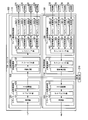
- 1 is a functional block diagram of an OTN framer 100 to which an embodiment of the present invention can be applied. It is a figure which shows the frame structure of OTUCn. OTLCn. It is a figure which shows the frame structure of n. It is a figure which shows the optical channel used for transmission of an optical signal. It is a figure which shows the optical channel used for transmission of an optical signal. It is a figure which shows the optical channel used for transmission of an optical signal. It is a figure which shows the optical channel used for transmission of an optical signal. 1 is a block diagram illustrating a configuration of an optical transmission system according to a first embodiment of the present invention. It is a block diagram which shows the structure of the time multiplexing process part 32 in 1st Embodiment.
- FIG. 6 is a diagram illustrating an operation example of the optical transmission device 30 and the optical reception device 40.
- FIG. 1 is a functional block diagram of an OTN framer 100 to which an embodiment of the present invention can be applied.
- the OTN framer 100 shown in the figure communicates with OTUCn (Cn represents 100 ⁇ n, where n is an integer equal to or greater than 2), which is an OTN standard for transmission of over 100 G (B100G, G is gigabit per second). I do.
- OTUCn Cn represents 100 ⁇ n, where n is an integer equal to or greater than 2
- B100G G is gigabit per second
- OTN optical network Transport technology
- client signals of various communication methods are accommodated and transferred by optical transmission.
- ODU0 Optical channel Data Unit
- GbE Gigabit Ethernet (registered trademark)
- G TS Triplebutary Slot
- the OTN framer 100 separates a signal of one optical channel of nx100G in which a plurality of client signals are multiplexed, and generates n 100G parallel signals.
- n parallel signals are multi-carrier transmitted by a plurality of optical subcarriers, but physically one parallel signal may be transmitted by one optical subcarrier, and a plurality of parallel signals are one It may be transmitted by an optical subcarrier.
- Multi-carrier transmission is a communication method for increasing the capacity of one channel by transmitting a signal of one channel in parallel using a plurality of optical subcarriers. In multicarrier transmission, subcarriers are densely multiplexed for each ground (connection destination) and electrically separated.
- the bandwidth of the optical subcarrier is 100G
- the bandwidth of the optical subcarrier is 200G
- 4SC-DP-QPSK (4 SubCarrier-Dual Polarization-Quadrature Phase Shift Keying)
- 2SC-DP-16QAM (2 SubCarrier-Dual Polarization-Quadrature Amplitude Modulation), etc. are used.
- the OTN framer 100 includes a transmission processing unit 110 and a reception processing unit 150.
- the transmission processing unit 110 includes a client signal receiving unit 120, a multiprocessing unit 130, and a line side transmission processing unit 140.
- the client signal receiving unit 120 includes a receiving unit 121, a mapping unit 122, and an OH processing unit 123.
- the receiving unit 121 receives a client signal.
- the mapping unit 122 maps one client signal received by the receiving unit 121 to the payload of a LO-ODU (Lower Order Optical Channel Channel Data Unit) frame.
- the OH processing unit 123 adds OH (overhead) to the LO-ODU frame in which the mapping unit 122 sets the client signal.
- the OH processing unit 123 outputs an electric path signal of the LO-ODU frame to the ODU-switch (hereinafter referred to as “ODU-SW”) 210.
- the ODU-SW 210 is also connected to other OTN framers 100, and performs path exchange of electrical path signals.
- the multiprocessing unit 130 includes a multiplexing unit 131 and a framing unit 132.
- the multiplexing unit 131 sets the electrical path signal received from the ODU-SW 210 in the LO-ODU frame.
- the multiplexing unit 131 once maps the LO-ODU frame to the ODTU (Optical channel data Data Tributary Unit) frame, and then time-multiplexes the plurality of ODTU frames to generate an ODUCn frame that is a HO-ODU (Higher Order Order ODU). .
- the framing unit 132 adds OH and FEC (forward error correction) to the ODUCn frame generated by the multiplexing unit 131 to generate an OTUCn frame.
- the framing unit 132 outputs the signal of the OTUCn frame to the line side transmission processing unit 140.
- the line side transmission processing unit 140 includes an interleaving unit 141, OH processing units 142-1 to 142-n, and multilane transmission units 143-1 to 143-n.
- the interleaving unit 141 receives an OTUCn frame signal from the multiprocessing unit 130, byte-interleaves the received n ⁇ 100G OTUCn frame signal, and generates n OTLCn.
- An n-frame signal is generated.
- the n frame is a frame of a 100 G parallel signal. i-th OTLCn. n frames, OTLCn. n # i frame (where i is an integer from 1 to n).
- the interleaving unit 141 includes the generated n OTLCn. Each n # i frame is output to the OH processing unit 142-i.
- the OH processing units 142-1 to 142-n receive the OTLCn.
- the OH processing unit 142-i is an OTLCn.
- the n # i frame is output to the multilane transmission unit 143-i.
- the multilane transmission units 143-1 to 143-n receive the OTLCn.1 received from the OH processing units 142-1 to 142-n.
- the n-frame parallel signal is output to the transmitter 220.
- the multi-lane transmission unit 143-i uses four 28G electric wires in parallel to perform OTLCn.
- the parallel signal of the n # i frame is output to the transmitter 220.
- Each transmitter 220 uses an optical subcarrier having a different wavelength.
- the transmitter 220 converts the received parallel signal from an electrical signal to an optical signal and performs multicarrier transmission.
- a plurality of multilane transmission units 143-i may be connected to one transmitter 220.
- the transmitter 220 transmits j parallel signals using j ⁇ 100G optical subcarriers. To transmit.
- the reception processing unit 150 includes a line-side reception processing unit 160, a separation processing unit 170, and a client signal transmission unit 180.
- the line side reception processing unit 160 includes multilane reception units 161-1 to 161-n, OH processing units 162-1 to 162-n, and a deinterleaving unit 163.
- Multilane receivers 161-1 to 161-n receive optical signals received by receiver 230 through multicarrier transmission as electrical signals.
- the receiver 230 receives optical signals using optical subcarriers having different wavelengths, converts the received optical signals into electrical signals, and outputs the electrical signals to the multilane receivers 161-1 to 161-n.
- the multilane receiving unit 161-i outputs, for example, the electrical signals received in parallel from the receiver 230 using four 28G electrical wirings to the OH processing unit 162-i.
- the OH processing units 162-1 to 162-n are OTLCn. Based on the FAS (Frame Alignment Signal) and MFAS (Multi Frame Alignment Signal) set in the OH of n frames, the head of the frame is detected from the received signal.
- the OH processing unit 162-i detects the head position, compensates for the delay time difference, and detects the OTLCn.
- the n # i frame is extracted and output to the deinterleave unit 163.
- the deinterleaving unit 163 receives the OTLCn.1 received from the OH processing units 162-1 to 162-n.
- n # n frames are deinterleaved to generate one OTUCn frame.
- the separation processing unit 170 includes a deframing unit 171 and a demultiplexing unit 172.
- the deframing unit 171 performs FEC decoding on the signal of the OTUCn frame generated by the deinterleaving unit 163, extracts an ODUCn frame in which the LO-ODU frame is time-multiplexed from the decoded OTUCn frame, and outputs the ODUCn frame to the demultiplexing unit 172.
- the demultiplexing unit 172 extracts the LO-ODU frame in which each client signal is set from the ODUCn frame signal extracted by the deframing unit 171, and outputs the LO-ODU frame electrical path signal to the ODU-SW 210.
- the client signal transmission unit 180 includes an OH processing unit 181, a demapping unit 182, and a transmission unit 183.
- the OH processing unit 181 receives the electric path signal from the ODU-SW 210, and decodes the LO-ODU frame from the received electric path signal.
- the OH processing unit 181 performs OH processing on the LO-ODU frame and outputs the OH processing unit 181 to the demapping unit 182.
- the demapping unit 182 receives the electrical path signal of the LO-ODU frame from the OH processing unit 181, extracts a client signal from the received electrical path signal, and outputs the client signal to the transmission unit 183.
- the transmission unit 183 transmits the client signal extracted by the demapping unit 182.
- the client signal receiving unit 120 and the multiplex processing unit 130 may directly input / output the electrical path signal of the LO-ODU frame without going through the ODU-SW 210.
- the separation processing unit 170 and the client signal transmission unit 180 may directly input / output the electric path signal of the LO-ODU frame without going through the ODU-SW 210.
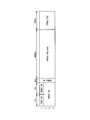
- FIG. 2 is a diagram showing the frame structure of OTUCn.
- OTUCn is generated by adding FACnOH, OTUCnOH, OPUCnOH, and OTUCnFEC to ODUCn.
- the frame structure of OTUCn is represented by 4 rows and 4080 ⁇ n columns.
- FIG. 2 shows a case where 256 bytes of FEC are added per row.
- OTUCn ((7 + 7 + 2) ⁇ n + 1) to 3824 ⁇ n columns of OPUCn payloads (Payload) are mapped with client signals.
- OH is set in the 1st to (7 + 7 + 2) ⁇ n columns of the OTUCn frame.
- FACnOH is set in the 1st to 7 ⁇ n columns of the first row in OH.
- the FACnOH includes information necessary for frame synchronization.
- OTUCnOH is set in the first row (7 ⁇ n + 1) to 14 ⁇ n columns in OH.
- the OTUCnOH contains section monitoring information for the optical channel.
- ODUCnOH is set in 1 to 14 ⁇ n columns of the 2nd to 4th rows in OH.
- ODUCnOH accommodates optical channel path management operation information.
- OPUCnOH is set in the (14 ⁇ n + 1) to 16 ⁇ n columns.
- OPUCnOH contains information necessary for mapping / demapping of client signals.
- OTUCnFEC is set in the 3824 ⁇ n + 1 to 4080 ⁇ n columns.
- the OTUCn FEC contains a parity check byte for FEC. Generally, when R bytes of FEC are added per row, FEC is set in the 3824 ⁇ n + 1 to (3824 + R) ⁇ n columns.
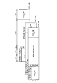
- FIG. 3 shows OTLCn. It is a figure which shows the frame structure of n. OTLCn. n is represented by 4 rows and 4080 columns. OTLCn. n # 1 to OTLC n. n # n is obtained by dividing the OTUCn frame by byte interleaving. The OTUCn payload of OTUCn is OTLCn. n # i of OPUCn. Maps to n # i payload.
- OTLCn. OH is set in the 1st to 16th columns of n # i. OTLCn.
- the OH of n # i is set based on OTUCnOH or the like.
- FALCn. n # iOH is set in the first to seventh columns of the first row.
- FALCn. n # iOH includes information necessary for frame synchronization.
- OTLCn. n # iOH is set.
- OTLCn. n # iOH accommodates section monitoring information of the optical channel.
- the 1-14 ⁇ n columns of the 2nd to 4th rows contain ODLCn.
- n # iOH is set. ODLCn.
- the n # iOH accommodates optical channel path management operation information.
- OPLCn. n # iOH is set.
- n # iOH stores information necessary for mapping / demapping of client signals.
- n # iFEC is set.
- the n # i FEC contains a parity check byte for FEC.
- FIGS. 4A to 4D are diagrams showing optical channels used for transmission of optical signals.
- 4A is a diagram showing an optical channel when a 400G optical signal is serially transmitted by one optical carrier
- FIG. 4B is a parallel transmission (multicarrier transmission) of a 400G optical signal by four optical subcarriers. It is a figure which shows the optical channel in case.
- OTUCn broadband transmission is realized without being restricted by the operation speed of the electronic circuit by performing parallel transmission of a band exceeding 100 G using a plurality of optical subcarriers.
- polarization multiplexing, multilevel modulation, or the like is used for this parallel transmission.
- the optical subcarrier band varies depending on the modulation method.
- FIG. 4B is an example in the case where one 400 G optical channel is transmitted in parallel by 100 G four optical subcarriers
- FIG. 4C is a case in which one 400 G optical channel is transmitted in parallel by 200 G two optical subcarriers. It is an example.
- multicarrier transmission has the flexibility to increase the transmission band in units of 100G as shown in FIG. 4D by changing n.
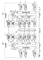
- FIG. 5 is a block diagram showing the configuration of the optical transmission system according to the first embodiment of the present invention.
- the optical transmission system according to the first embodiment includes an optical transmission device 30, an optical reception device 40, and a transmission path 50 (optical fiber).
- FIG. 5 shows a frame structure used in the optical transmitter 30 and the optical receiver 40.
- the optical transmission device 30 includes a plurality of client accommodation units 31, a time multiplexing processing unit 32, a transmission frame generation unit 33, i subcarrier transmission units 34-1 to 34-i, a TS (time slot) control unit 35, and a power source. And a control unit 36.
- the client accommodating unit 31 corresponds to the client signal receiving unit 120 in FIG.
- the time multiplexing processing unit 32 corresponds to the ODU-SW 210 and the multiplexing unit 131 in FIG.
- the transmission frame generation unit 33 corresponds to the framing unit 132 and the line side transmission processing unit 140 in FIG.
- Each of the subcarrier transmission units 34-1 to 34-i corresponds to the transmitter 220 in FIG.
- the optical transmission device 30 according to the first embodiment is different from the configuration of the transmission processing unit 110 in the OTN framer 100 illustrated in FIG. 1 in that the configuration includes the TS control unit 35 and the power supply control unit 36.
- the client accommodation unit 31 receives the client signal and accommodates the received client signal in the frame structure of the electric path.
- ODU is used as a frame structure of an electric path.
- the client accommodation unit 31 outputs the electrical path signal containing the client signal to the time multiplexing processing unit 32.
- the time multiplexing processing unit 32 time-multiplexes the electrical path signals output from each of the plurality of client accommodation units 31.
- the time multiplexing processing unit 32 assigns each of the input plurality of electric path signals to any of the plurality of time slots included in the transmission frame, and accommodates the electric path signals in the assigned time slots.
- the time multiplexing processing unit 32 multiplexes the electrical path signal by accommodating the electrical path signal in the time slot of the transmission frame.
- the time multiplexing processing unit 32 assigns the electrical path signal to one or a plurality of time slots according to the capacity of the electrical path signal.
- FIG. 6 is a block diagram showing a configuration of the time multiplexing processing unit 32 in the first embodiment.
- the time multiplex processing unit 32 includes a plurality of stuff addition units 321, a plurality of write processing units 322, and a buffer memory 323.
- a plurality of staff addition units 321 are provided corresponding to each of the client accommodation units 31.
- Each staff adding unit 321 inputs an electric path signal output from the corresponding client accommodating unit 31.
- the stuff addition unit 321 adds a stuff byte to the input electric path signal and adjusts the capacity to the same capacity as the time slot that accommodates the electric path signal.
- the stuff addition unit 321 outputs the electrical path signal with the stuff byte added thereto to the write processing unit 322.
- Each of the plurality of write processing units 322 is provided corresponding to each of the staff addition units 321.
- Each writing processing unit 322 receives an electric path signal to which a stuff byte is added from a corresponding stuff adding unit 321.
- the write processing unit 322 combines the write address corresponding to the time slot determined for each electrical path and the data, outputs the combined data to the buffer memory 323, and writes the data in the area corresponding to the address.
- Each write processing unit 322 acquires a write address from the TS control unit 35.
- Data to be written to the buffer memory 323 is an electric path signal to which stuff bytes are added.
- the buffer memory 323 has a storage capacity larger than the time slot capacity of the transmission frame.
- the buffer memory 323 stores the data input by each writing processing unit 322 and outputs the stored data to the transmission frame generation unit 33 for each transmission frame period. Note that the buffer memory 323 may sequentially output the data written by each write processing unit 322 to the transmission frame generation unit 33.
- the time multiplexing processing unit 32 assigns LO-ODUs output from each of the plurality of client accommodation units 31 to time slots in the HO-ODU, and accommodates the LO-ODUs in the assigned time slots.
- LO-ODU is allocated to n ⁇ 80 1.25G time slots possessed by ODUCn.
- ODU2 is used as LO-ODU, since ODU2 has a bandwidth of about 10G, ODU2 is allocated to eight time slots to accommodate ODU2.
- ODU3 is used as LO-ODU, since ODU3 has a bandwidth of about 40 G, ODU3 is allocated to 31 time slots to accommodate ODU3.
- the configuration in which ODUCn has n ⁇ 80 1.25G time slots is an example, and the capacity per time slot that ODUCn has may be other than 1.25G described above.
- the transmission frame generation unit 33 adds overhead information or an error correction code to the data for one transmission frame output from the time multiplexing processing unit 32.
- the transmission frame generation unit 33 generates a transmission signal in which a signal obtained by adding overhead information and an error correction code to data is distributed to the number of subcarriers used for transmission.
- the transmission frame generation unit 33 outputs the generated transmission signal to the corresponding subcarrier transmission units 34-1 to 34-i.
- Each of the subcarrier transmitting units 34-1 to 34-i performs electro-optical conversion on the transmission signal output from the transmission frame generating unit 33, and uses the optical signal obtained by the electro-optical conversion as a subcarrier signal. Output.
- the subcarrier signals output from the subcarrier transmission units 34-1 to 34-i are generated using carrier lights having different wavelengths.
- the subcarrier signals output from the subcarrier transmitters 34-1 to 34-i are transmitted to the optical receiver 40 via the transmission path 50.
- the same optical fiber of the same path is generally used, but different optical fibers of the same path can be used, or optical fibers of different paths can be used.
- the TS control unit 35 inputs and outputs control information between the time multiplexing processing unit 32 and the transmission frame generation unit 33.
- Control information between the TS control unit 35 and the time multiplexing processing unit 32 includes a write address when writing data to the buffer memory 323, information for instructing each write processing unit 322 to change the write address, and the like. Is included.
- the TS control unit 35 has a time slot usage status table, and instructs each write processing unit 322 about a write address based on the table.
- Control information between the TS control unit 35 and the transmission frame generation unit 33 includes information specifying the subcarrier transmission unit 34 used for transmission among the subcarrier transmission units 34-1 to 34-i.
- the TS control unit 35 notifies the power supply control unit 36 of the subcarrier transmission unit 34 used for transmission and the subcarrier transmission unit 34 not used for transmission based on the time slot usage status table.
- the power supply control unit 36 performs control to supply power to the subcarrier transmission unit 34 used for transmission and stop supplying power to the subcarrier transmission unit 34 not used for transmission.
- the optical receiver 40 includes i subcarrier receivers 41-1 to 41-i, a transmission frame termination unit 42, a time demultiplexing unit 43, a plurality of client playback units 44, a TS control unit 45, and a power supply control unit 46.
- Each of the subcarrier receiving units 41-1 to 41-i corresponds to the receiver 230 in FIG.
- the transmission frame termination unit 42 corresponds to the line side reception processing unit 160 and the deframing unit 171 in FIG.
- the time demultiplexing processing unit 43 corresponds to the demultiplexing unit 172 and the ODU-SW 210 in FIG.
- the client reproduction unit 44 corresponds to the client signal transmission unit 180 in FIG.
- the subcarrier receiving units 41-1 to 41-i are provided corresponding to the subcarrier transmitting units 34-1 to 34-i, respectively.
- the subcarrier receiving units 41-1 to 41-i receive the subcarrier signals transmitted from the corresponding subcarrier transmitting units 34-1 to 34-i.
- the subcarrier receivers 41-1 to 41-i perform optical-electrical conversion on the received subcarrier signals, and output the electrical signals obtained by the photoelectric conversion to the transmission frame termination unit 42 as received signals.
- the transmission frame termination unit 42 combines the reception signals output from the subcarrier reception units 41-1 to 41-i to restore the transmission frame.
- the transmission frame termination unit 42 detects the frame boundaries of the received signals when combining the received signals, and compensates for the difference (de-skew) if there is a difference in the transmission delay between the frames. .
- the transmission frame termination unit 42 reads the overhead information of the restored transmission frame and performs error correction decoding using an error correction code added to the transmission frame.
- the transmission frame termination unit 42 outputs the decoded data for one transmission frame to the time demultiplexing processing unit 43.
- the transmission frame terminating unit 42 performs error correction decoding on the received signals of the subcarrier receiving units 41-1 to 41-i individually, and then combines the error correction decoded received signals to transmit the transmission frame. May be restored.
- the time demultiplexing processing unit 43 demultiplexes the data output from the transmission frame terminating unit 42 and separates it into a plurality of electric path signals.
- the time demultiplexing unit 43 outputs a plurality of electrical path signals obtained by separation to the corresponding client reproduction unit 44.
- FIG. 7 is a block diagram illustrating a configuration of the time demultiplexing unit 43 in the first embodiment.
- the time demultiplexing processing unit 43 includes a buffer memory 431, a plurality of reading processing units 432, and a plurality of staff deleting units 433.
- the buffer memory 431 stores the data input from the transmission frame termination unit 42 in the input order.
- the buffer memory 431 outputs the data stored in the storage area specified by the read address specified by the read processing unit 432 to the read processing unit 432.
- the storage area specified by the read address corresponds to the time slot of the transmission frame.
- Each of the plurality of read processing units 432 is provided corresponding to an electrical path.
- the read processing unit 432 acquires the data of the time slot assigned to the corresponding electrical path from the buffer memory 431.
- the read address corresponding to the time slot assigned to the electrical path corresponding to the read processing unit 432 is input from the TS control unit 45 to each read processing unit 432.
- the read processing unit 432 outputs the read address acquired from the TS control unit 45 to the buffer memory 431, acquires the data stored in the storage area of the read address, and outputs the data to the staff deletion unit 433.
- Each of the plurality of staff deletion units 433 is provided corresponding to the electric path.
- the staff deletion unit 433 receives data output from the read processing unit 432 assigned to the corresponding electrical path.
- the staff deletion unit 433 deletes the stuff byte added to the input data, extracts the original electrical path signal, and outputs the extracted electrical path signal to the client playback unit 44.
- Each of the plurality of client playback units 44 is provided corresponding to an electrical path.
- the client playback unit 44 inputs the electrical path signal of the corresponding electrical path from the staff deletion unit 433.
- the client reproduction unit 44 extracts a client signal from the input electrical path signal and transmits it.
- the TS control unit 45 inputs and outputs control information between the transmission frame termination unit 42 and the time demultiplexing processing unit 43.
- the control information between the TS control unit 45 and the transmission frame termination unit 42 includes information specifying the subcarrier receiving unit 41 used for transmission among the subcarrier receiving units 41-1 to 41-i.
- the TS control unit 45 notifies the power supply control unit 46 of the subcarrier receiving unit 41 used for transmission and the subcarrier receiving unit 41 not used for transmission.
- the power supply control unit 46 performs control to supply power to the subcarrier reception unit 41 used for transmission and stop supplying power to the subcarrier reception unit 41 not used for transmission.
- Control information between the TS control unit 45 and the time demultiplexing processing unit 43 includes a read address when reading data from the buffer memory 431, information for instructing each read processing unit 432 to change the read address, and the like. Is included.
- the TS control unit 35 of the optical transmission device 30 instructs the time multiplexing processing unit 32 to change the time slot assignment after a predetermined time (after T frame). Based on an instruction from the TS control unit 35, the time multiplexing processing unit 32 performs time slot allocation change at the boundary of the transmission frame after the time of T frames has elapsed.
- the TS control unit 35 notifies the optical receiver 40 that the change of the time slot allocation will be performed after a certain time, using the overhead information added by the transmission frame generation unit 33.
- the transmission frame termination unit 42 of the optical receiver 40 detects that the notification of changing the allocation of the time slot is included in the overhead information of the transmission frame, the transmission frame termination unit 42 outputs the notification to the TS control unit 45.
- the TS control unit 45 outputs the notification to the time demultiplexing processing unit 43.
- the time demultiplexing unit 43 performs time slot assignment change at the boundary of the transmission frame after the time of T frames has elapsed.
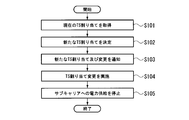
- FIG. 8 is a flowchart showing processing when changing the time slot to which the electric path signal is allocated.
- the process of changing the allocation of the time slot is based on an index indicating the degree of fragmentation of the time slot of the transmission frame (time slot fragmentation) when a start instruction is received from the administrator of the optical transmission system. If it exceeds, it is executed at a designated timing such as daily, weekly, or monthly.
- an index indicating the degree of fragmentation for example, a value calculated using Expression (1) may be used. (Number of used subcarriers) ⁇ ((number of used time slots) / (number of time slots per subcarrier)) (1)
- the TS control unit 35 of the optical transmission device 30 acquires the assignment of each electric path signal to the time slot of the transmission frame (step S101).
- the TS control unit 35 changes the assignment of each electric path signal to the time slot of the transmission frame, and determines the assignment of a new time slot that eliminates fragmentation (step S102).
- the TS control unit 35 outputs the determined time slot assignment and a notification for changing the time slot assignment to the transmission frame generation unit 33, and notifies the allocation and change notification via the transmission frame generation unit 33 to the optical receiver 40. Send to.
- the transmission control unit 45 transmits the detected allocation and notification to the TS control unit 45.
- the notification for changing the time slot assignment includes information indicating the timing for changing the time slot assignment (information indicating the time after the T frame).
- the TS control unit 35 of the optical transmission device 30 notifies the time multiplexing processing unit 32 of the new assignment before the process for the frame whose time slot assignment is to be changed, and changes the assignment to the time slot.
- the TS control unit 45 of the optical receiver 40 notifies the time demultiplexing processing unit 43 of the new assignment before executing the process for the frame whose time slot assignment is changed, and changes the assignment to the time slot. (Step S104).
- the TS control unit 35 controls the power supply control unit 36 to stop the power supply to the subcarrier transmission unit 34 that does not transmit the time slot to which the electric path signal is allocated in the new allocation.
- the TS control unit 45 controls the power supply control unit 46 to stop the supply of power to the subcarrier receiving unit 41 that does not transmit the time slot to which the electric path signal is allocated in the new allocation (step) S105).
- the TS control unit 35 and the TS control unit 45 The process of changing the allocation of time slots is terminated without performing control on the power supply control unit 46 and the power supply control unit 46.
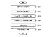
- FIG. 9 is a flowchart showing a different process when changing the time slot to which the electric path signal is allocated.
- the process shown in FIG. 8 is a process accompanied by a reduction in subcarriers used, whereas the process shown in FIG. 9 is a process accompanied by an increase in subcarriers used.
- the TS control unit 35 of the optical transmission device 30 acquires the assignment of each electric path signal to the time slot of the transmission frame (step S201).
- the TS control unit 35 changes the assignment of the electric path signal to the time slot of the transmission frame and determines the assignment of the new time slot in order to add a new electric path signal or increase the capacity of the existing electric path signal. (Step S202).
- the TS control unit 35 outputs the determined time slot assignment and a notification for changing the time slot assignment to the transmission frame generation unit 33, and notifies the allocation and change notification via the transmission frame generation unit 33 to the optical receiver 40. Send to.
- the transmission frame terminating unit 42 detects the allocation of the time slot and the notification for changing the allocation in the overhead information of the transmission frame received from the optical transmitting device 30, the detected allocation and the notification are TS-controlled. It outputs to the part 45 (step S203).
- the TS control unit 35 starts supplying power to the subcarrier transmitting unit 34 that has stopped supplying power among the subcarrier transmitting units 34 that transmit the time slot to which the electric path signal is allocated in the new allocation.
- the power supply control unit 36 is controlled.
- the TS control unit 45 transmits power to the subcarrier receiving unit 41 that has stopped supplying power among the subcarrier receiving units 41 that transmit the time slot to which the electric path signal is allocated in the new allocation. Control for starting the supply is performed on the power supply controller 46. (Step S204).
- the TS control unit 35 and the TS control unit 45 cause the transmission frame generation unit 33 and the transmission frame termination unit 42 to check the normality of the subcarrier transmission unit 34 and the subcarrier reception unit 41 that have started supplying power. (Step S205).
- the TS control unit 35 of the optical transmission device 30 notifies the time multiplexing processing unit 32 of the new assignment before the process for the frame whose time slot assignment is to be changed, and changes the assignment to the time slot.
- the TS control unit 45 of the optical receiver 40 notifies the time demultiplexing processing unit 43 of the new assignment before executing the process for the frame whose time slot assignment is changed, and changes the assignment to the time slot. (Step S206).
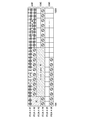
- FIG. 10A to FIG. 10C are diagrams showing an example of changing the time slot to which the electric path signal is allocated.
- 100G transmission is performed per subcarrier
- 400G transmission is performed using four subcarriers (SC # 1 to SC # 4).
- the capacity of one time slot is 10G
- each subcarrier includes 10 time slots.
- 10A to 10C the vertical axis represents the subcarrier
- the horizontal axis represents the time slot.
- FIG. 10A shows a case where fragmentation occurs by repeatedly opening and deleting an electrical path multiplexed on a 400 G signal. In this case, it is necessary to perform transmission using all subcarriers even though the traffic (electrical path signal) actually transmitted is small, and resources are wasted. Specifically, only 20 time slots out of 40 time slots, that is, traffic of 200 G is accommodated, but it can be said that resources are wasted because all four subcarriers are operated.
- FIG. 10B shows time slot assignment after a change is made to the time slot assignment shown in FIG. 10A.
- the four electric path signals can be transmitted without assigning the electric path signals to the two subcarriers (SC # 3, SC # 4). It is possible.
- FIG. 10C by stopping the power supply to the subcarrier transmission unit 34 and the subcarrier reception unit 41 corresponding to the two subcarriers (SC # 3, SC # 4), Utilization efficiency can be improved.
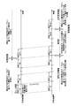
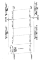
- FIG. 11 is a diagram illustrating an operation example of the optical transmission device 30 and the optical reception device 40.
- the horizontal axis represents time.
- the optical transmission device 30 notifies the optical reception device 40 of the switching information in the transmission frame # 1.
- the switching information includes new allocation of time slots and information indicating timing for switching to multiplexing using the allocation. Instead of the new assignment of the time slot, the switching information may include information indicating a change place between the current assignment of the time slot and the new assignment of the time slot.
- the assignment of the electric path signal to the time slot is switched at the boundary between the transmission frame #n and the transmission frame # n + 1. That is, in the example illustrated in FIG. 11, information indicating that the assignment is switched after n transmission frames is included in the switching information.
- the optical transmission device 30 time-multiplexes the electrical path signal in the transmission frame based on the current allocation of time slots. After transmission frame # n + 1, the optical transmission device 30 time-multiplexes the electrical path signal in the transmission frame based on the new assignment of time slots.
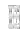
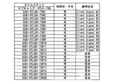
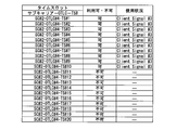
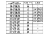
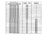
- FIG. 12A to 12B are diagrams showing an example of a time slot usage status table that the TS control unit 35 has. This figure shows a time slot usage status table corresponding to the allocation shown in FIG. 10A.
- the electric path signal assigned to the time slot is associated with each time slot.
- a time slot to which no electrical path signal is assigned is associated with “vacant” indicating that it is not used.
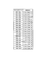
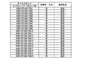
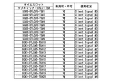
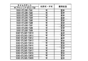
- FIG. 13A to FIG. 13B are diagrams showing different examples of the time slot usage status table that the TS control unit 35 has. In the figure, a time slot usage table corresponding to the assignment shown in FIG. 10B is shown.
- time slot TS # 1 of subcarrier SC # 1 is the first time slot
- time slot TS # 10 of subcarrier SC # 4 is the last time slot.
- the TS control unit 35 searches for the electric path signal assigned to the time slot in order from the last time slot toward the first time slot.
- the search is started sequentially from the time slot TS # 10 of the subcarrier SC # 4, an electric path signal (Client Signal # 2) is detected in the time slot TS # 9 of the subcarrier SC # 4. To do.
- the TS control unit 35 When the TS control unit 35 detects the electrical path signal assigned to the time slot, the TS control unit 35 searches for the time slot to which the electrical path signal is not assigned in order from the first time slot. In the example of FIGS. 12A to 12B, when the search is started in order from time slot TS # 1 of subcarrier SC # 1, time slots to which no electrical path signal is assigned to time slot TS # 6 of subcarrier SC # 1 are displayed. To detect.
- the TS control unit 35 When the TS control unit 35 detects a time slot to which no electric path signal is assigned, the TS control unit 35 assigns the detected electric path signal to the time slot.
- the detected electric path signal (Client Signal # 2) is assigned to the time slot TS # 6 of the subcarrier SC # 1.
- the TS control unit 35 repeats this process to aggregate the time slots to which the electric path signals are assigned to the head side, and the time slots to which the electric path signals are not assigned to the last side.
- the TS control unit 35 repeats the processing, in the example of FIGS. 12A to 12B, the assignment of the electrical path signals (Client Signal # 4) of the time slots TS # 2 to TS # 5 of the subcarrier SC # 4 is changed to the subcarrier SC. It is changed to # 1 time slots TS # 7 to TS # 10.
- the assignment of the electrical path signals (Client Signal # 3) of the time slots TS # 6 to TS # 10 of the subcarrier SC # 3 is changed to the time slots TS # 1 to TS # 5 of the subcarrier SC # 2.
- the new assignment of time slots to the electric path signals (Client Signal # 1 to # 4) is determined as the assignment shown in FIGS. 13A to 13B.
- the optical subcarrier modulation method preferably has a small number of subcarriers from the viewpoint of wavelength resource and device cost. However, when determining the modulation scheme, a modulation scheme having a longer transmission distance (transmission distance) than the actual transmission distance is selected.
- the transmission distance varies depending on the modulation method, and is in the order of QPSK> 8QAM> 16QAM.
- the transmission rate of QPSK is basic rate ⁇ 2 bits
- the transmission rate of 8QAM is basic rate ⁇ 3 bits
- the transmission rate of 16QAM is basic rate ⁇ 4 bits.
- the optical transmission band is constant, the number of subcarriers is in the order of QPSK> 8QAM> 16QAM.
- 25G is generally used as the basic rate.
- the OTUCn frame is in units of 100G regardless of the optical subcarrier bandwidth, if the optical subcarrier bandwidth is not a multiple of 100G, the fractional bandwidth must be considered.
- the optical subcarrier band is 150G, the 50G band (time slot) in the OTUC2 frame is disabled and the client signal is not accommodated (time slot).
- the client signal is not accommodated (time slot).
- the bandwidth of one OTLC 4.4 frame is 100G. If one time slot band is 5G and two OTLC 4.4 frames are one set, the maximum band and the number of time slots are 200G and 40 time slots. When accommodating 150 G of information per subcarrier, 30 time slots (150 G) are set to be usable, and the remaining 10 time slots (50 G) are set to be unusable.
- OTUCn-M When the number of OTLC 4.4 frames is n and the number of usable time slots is M, it is expressed as OTUCn-M. For example, when 30 time slots can be used in 2 OTLC 4.4 frames, they are expressed as OTUC2-30.
- the subcarrier band is BWSC (G bits per second)
- the time slot band is BWTS (G bits per second)
- M N ⁇ Ceil (BWSC / BWTS)
- n N ⁇ Ceil (BWSC / 100) It becomes.
- Ceil (x) is a function that gives the smallest integer equal to or greater than x.
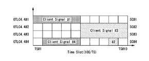
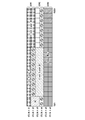
- FIGS. 14A to 14C show examples of changing the time slot to which the electric path signal is allocated in view of the above background.
- a time slot marked with a combination of a circle and a diagonal line indicates an unusable band (time slot).
- 150G is transmitted per subcarrier, and 450G is transmitted using three subcarriers (SC # 1 to SC # 3).
- FIGS. 14A to 14C show the case of OTUC6-90.
- usable time slots can be arbitrarily arranged in each set of OTLC 4.4. Further, when there is no information to be accommodated, the usable time slot is empty.
- FIG. 14A shows a state in which fragmentation occurs in time slot assignment by repeatedly opening and deleting electrical paths.
- 52 26G
- FIG. 14B shows time slot assignment after a change has been made to the time slot assignment shown in FIG. 14A.
- FIG. 14B it is possible to transmit four electrical path signals without assigning electrical path signals to one subcarrier (SC # 3).
- the power use efficiency is improved by stopping the supply of power to the subcarrier transmission unit 34 and the subcarrier reception unit 41 corresponding to one subcarrier (SC # 3). Can be made.
- a value calculated by equation (2) can be used. (Number of used subcarriers) ⁇ ((number of used time slots) / (number of time slots per subcarrier ⁇ 1 ⁇ number of unusable time slots per subcarrier)) (2)
- the procedure for the TS control unit 35 to determine a new assignment is basically the same as the procedure described with reference to FIGS. 12A to 13B. The difference from the above-described procedure is that, in addition to the time slot to which the electrical path signal is assigned, a search is made for an unavailable time slot, and the same number (10 in the illustrated example) of unavailable time slots. Is included in each subcarrier.
- the position of the usable time slot and the position of the unusable time slot may be exchanged. Therefore, in FIG. 14B and FIG. And the state after exchanging unusable time slots. Further, the information on the time slot allocation in the time slot usage status table includes information on the position of the unusable time slot.
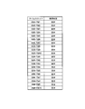
- FIG. 15A to 15F are diagrams illustrating an example of a time slot usage status table included in the TS control unit 35.
- FIG. This figure shows a time slot usage status table corresponding to the allocation shown in FIG. 14A.
- FIG. 16A to FIG. 16F are diagrams showing an example of a time slot usage status table that the TS control unit 35 has. In the same figure, a time slot usage table corresponding to the allocation shown in FIG. 14B is shown.
- the subcarrier transmission unit 34 converts the signal of the time slot excluding the unusable time slot into an optical signal based on the time slot usage status table, and converts the obtained optical signal into the optical signal. Output as a subcarrier signal.
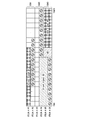
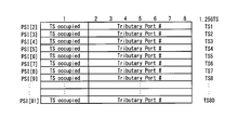
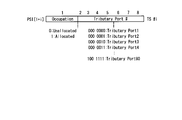
- FIGS. 17A to 17B are diagrams showing time slot usage status tables in OTN.
- MSI Multiplex Structure Identifier
- the TS control unit 35 of the optical transmitter 30 includes the time slot usage status table shown in FIGS. 12A to 12B, 13A to 13B, 15A to 15F, 16A to 16F, or 17A to 17B. Then, the timing information for changing the allocation of the time slot for the electric path signal is notified to the TS control unit 45 of the optical receiver 40 using the empty area of the overhead information of the transmission frame.
- FIG. 18 is a diagram illustrating a frame structure of OTUk.
- GCC0 and RES in the OTUkOH from the 11th column to the 14th column of the first row can be used for notification.
- FIG. 19 is a diagram illustrating a frame structure of ODUk.
- RES from the first column to the second column of the second row in the ODUkOH, GCC1 and GCC2 from the first column to the fourth column of the fourth row, and fourteenth columns from the ninth column to the fourth row. RES up to the eye can be used for notification.
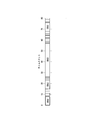
- the MSI is provided with a number of protection stages for enhancing resistance against bit errors, and the optical receiver 40 receives a fixed number of times from the optical transmitter 30 in the notification of a new time slot usage status table (MSI). After receiving the same MSI a number of times, it starts to be used as a new MSI. Further, since MSI is notified from the optical transmission device 30 to the optical reception device 40 using a plurality of transmission frames called multiframes, there is a case where a waiting time is required until the multiframe is completed. In the case of OTN, MSI is notified once every 256 frames. Therefore, in such a transient state, as shown in FIG.
- the optical receiver 40 in the optical receiver 40, between the transmission frame # n + 1 and the transmission frame # n + m, the time multiplexed signal is correctly time-demultiplexed and the electric path signal is separated. It cannot be done and the signal is cut off. After transmission frame # n + m + 1, the optical receiver 40 can separate the electric path signal by time demultiplexing with respect to the transmission frame using the new MSI.
- the following operations can be considered.
- the network management system can handle the capacity of this transmission path as 400G.
- the power transmission to the subcarrier transmission unit 34 and the subcarrier reception unit 41, in which the power supply is stopped is stopped in the background, and the power supply is stopped.
- the network management system can perform management without controlling the subcarrier use suspension and use resumption.
- the capacity of this transmission line may be handled as 200G.
- the network management system detects a decrease in capacity due to the suspension of subcarrier usage.
- the subcarrier usage is resumed and the capacity is changed from 200G to 300G or 400G.
- the former operation is equivalent to handling the OTUC4 transmission path even after the subcarrier usage is stopped, and the latter operation is changed from the OTUC4 transmission path to the OTUC2 transmission path after the subcarrier usage is stopped. It corresponds to doing.
- a frame structure in which overhead bytes for signal management are provided for each signal transmitted by each subcarrier may be used.
- this frame structure when any subcarrier has overhead information as a subcarrier representing the transmission path, all subcarriers have the same overhead information, or they are mixed depending on the type of overhead information. There may be.
- power supply to subcarriers is stopped when fragmentation of time slots is eliminated, handling of overhead information must also be considered.
- the subcarrier when only a specific subcarrier has overhead information, the subcarrier is treated as a representative subcarrier, and the allocation to the time slot is changed so that power supply to the representative subcarrier is continued.
- the electric path signal is preferentially assigned to the time slot corresponding to the representative subcarrier, or when the power supply to the representative subcarrier is stopped, the subcarrier to which the electric path signal is assigned is designated as the representative subcarrier. Or change it to
- the time is increased. Change the assignment of electrical path signals to the slots.
- the resource utilization efficiency is improved by stopping the operations of the subcarrier transmission unit 34 and the subcarrier reception unit 41 corresponding to the subcarrier. Can do.
- the optical transmission system when changing the assignment to the time slot, the optical transmission system can be used because of the protection period in which the same MSI is received a certain number of times and then the use is started as a new MSI, or the waiting time for one round of transmission multiframe. A signal interruption occurred in the receiving device 40 (FIG. 11).
- the optical transmission system according to the second embodiment operates so as not to cause signal interruption when changing the assignment of the electrical path signal to the time slot.
- the setting of the protection period is temporarily canceled when switching the time slot usage status table, and the MSI is changed without receiving the same MSI for a certain number of times.
- FIG. 20 is a diagram illustrating an operation example of the optical transmission device 30 and the optical reception device 40 in the second embodiment.
- the horizontal axis represents time.
- the optical receiver 40 receives the updated time slot usage status table from transmission frame # 1 to transmission frame #n.
- the optical receiver 40 separates the electrical path signal from the transmission frame # n + 1 by demultiplexing the transmission frame from the transmission frame # n + 1 without using a protection period after the transmission frame #n by using the updated time slot usage status table.
- the optical transmission device 30 receives the updated time slot usage status table multiple times from transmission frame # 1 to transmission frame #n. You may make it transmit to the apparatus 40.
- FIG. Thereby, even when a bit error occurs in the transmission of the time slot usage table, it is possible to prevent erroneous demultiplexing from being performed in the optical receiver 40.
- the timing for starting multiplexing based on the updated time slot usage status table is set so that the round-trip waiting period of the transmission multiframe is included, and the time slot usage status table is set in advance. You may make it transmit to the optical receiver 40.
- TS control unit 35 changes the write address for each write processing unit 322, and TS control unit 45 reads the read address for each read processing unit 432. Is changed to change the time slot usage status table.
- the time slot usage status table can be switched without causing signal interruption.
- FIG. 21 is a block diagram illustrating a configuration of an optical transmission system according to the third embodiment. As shown in the figure, the optical transmission system according to the third embodiment includes an optical transmission device 30A, an optical reception device 40A, and a transmission path 50.
- the optical transmission device 30A includes a plurality of client accommodation units 31, a time multiplexing processing unit 32, a transmission frame generation unit 33, i subcarrier transmission units 34-1 to 34-i, a TS (time slot) control unit 35, and a power source.
- a control unit 36 and a control signal transmission unit 39 are provided.
- the same components as those included in the optical transmission device 30 are denoted by the same reference numerals, and description thereof is omitted.
- the control signal transmission unit 39 receives the switching information from the TS control unit 35 and transmits the switching information to the optical reception device 40 ⁇ / b> A through a path different from the transmission path 50.
- the TS control unit 35 outputs the switching information to the control signal transmission unit 39 instead of outputting the switching information to the transmission frame generation unit 33.
- the optical receiver 40A includes i subcarrier receivers 41-1 to 41-i, a transmission frame termination unit 42, a time demultiplexing unit 43, a plurality of client reproducing units 44, a TS control unit 45, and a power supply control unit 46. And a control signal receiving unit 49.
- the control signal receiving unit 49 receives the switching information transmitted by the control signal transmitting unit 39 and outputs the switching information to the TS control unit 45.
- the TS control unit 45 inputs switching information from the control signal receiving unit 49 instead of inputting switching information from the transmission frame terminating unit 42.
- the switching information is transmitted at an arbitrary timing, and the time slot usage state without causing signal interruption You can switch tables.
- Wavelength division multiplexing may be applied to the optical transmission systems in the first, second, and third embodiments.
- the optical transmission system in the fourth embodiment is an optical transmission system to which wavelength division multiplexing is applied.
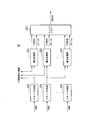
- FIG. 22 is a block diagram illustrating a configuration of an optical transmission system according to the fourth embodiment.
- the optical transmission system according to the fourth embodiment includes a plurality of optical transmitters 30, a wavelength multiplexer 61, a transmission path 50, a wavelength separator 62, and a plurality of optical receivers 40. Since the optical transmission device 30 and the optical reception device 40 in the fourth embodiment have the same configuration as the optical transmission device 30 and the optical reception device 40 (FIG. 5) in the first embodiment, redundant descriptions are omitted.
- the wavelength multiplexing unit 61 multiplexes optical signals of different wavelengths output from the respective optical transmission devices 30 and outputs the multiplexed optical signals to one transmission path 50 (optical fiber).
- the wavelength separation unit 62 separates the optical signal received from the transmission path 50 for each wavelength, and outputs the optical signal separated for each wavelength to the optical receiver 40 for each predetermined number of optical signals.
- the transmission capacity in one transmission line 50 can be improved by wavelength-multiplexing a plurality of subcarriers used in multicarrier transmission.
- the optical transmission system may include an optical transmission device 30A and an optical reception device 40A instead of the optical transmission device 30 and the optical reception device 40.
- the timing for changing the allocation of the electrical path signal to the time slot is designated as a fixed time (after T frame)
- T frame the timing may be specified by other methods without being limited to this. For example, when an identifier that can be uniquely identified is assigned to each transmission frame, the timing may be specified by the identifier of the transmission frame.
- the set of the subcarrier transmission unit 34 and the subcarrier reception unit 41 that are stopped from supplying power is selected by round robin scheduling. May be.
- the operating time of the subcarrier transmission unit 34 and the subcarrier reception unit 41 can be averaged to extend the usage period of the apparatus.
- a laser oscillator used in optical communication has a shorter use period depending on the energization time, so that the use period of the entire system can be extended by averaging the energization time.
- the framing unit 132, the deframing unit 171, the transmission frame generation unit 33, and the transmission frame termination unit 42 perform processing related to FEC (addition of FEC (error correction code), FEC decoding (error correction decoding)). Absent.
- processing related to FEC may be performed by the transmitter 220 and the receiver 230, for example.
- the optical transmission device and optical reception device in the above-described embodiment may be realized by a computer.
- a program for realizing each component included in the optical transmission device and the optical reception device is recorded on a computer-readable recording medium, and the program recorded on the recording medium is read into the computer system and executed. May be realized.
- the “computer system” includes hardware such as an OS (Operating System) and peripheral devices.
- “Computer-readable recording medium” means a portable medium such as a flexible disk, a magneto-optical disk, a ROM (Read Only Memory), a CD (Compact Disk) -ROM, or a hard disk built in a computer system. Refers to the device.
- the “computer-readable recording medium” is a program that dynamically holds a program for a short time, like a communication line when a program is transmitted via a network such as the Internet or a communication line such as a telephone line.
- a volatile memory inside a computer system serving as a server or a client in that case may be included and a program held for a certain period of time.
- the program may be for realizing a part of the above-described constituent elements, and may be realized by combining the above-described constituent elements with a program already recorded in a computer system. Good.
- the optical transmission device and the optical reception device may be realized using hardware such as PLD (Programmable Logic Device) and FPGA (Field Programmable Gate Gate Array).
- the present invention can also be applied to uses for improving resource utilization efficiency in multicarrier transmission.
- Optical transmission device 31: Client accommodation unit, 32: Time multiplexing processing unit, 33: Transmission frame generation unit, 34, 34-1, 34-2, 34-4, 34-i ... Subcarrier transmission unit , 35... TS control section, 36... Power supply control section, 39... Control signal transmission section, 40, 40 A... Optical reception apparatus, 41, 41-1, 41-2, 41-3, 41 -i. , 42 ... Transmission frame termination unit, 43 ... Time demultiplexing unit, 44 ... Client playback unit, 45 ... TS control unit, 46 ... Power supply control unit, 49 ... Control signal receiving unit, 50 ... Transmission path, 61 ... Wavelength multiplexing , 62 ... wavelength separation unit, 100 ... framer, 110 ...
- transmission processing unit 120 ... client signal reception unit, 121 ... reception unit, 122 ... mapping unit, 123 ... OH processing unit, 130 ... multiplex processing unit, 131 ... multiplex Chemical department 132 ... framing unit, 140 ... line side transmission processing unit, 141 ... interleaving unit, 142, 142-1, 142-2, 142-3, 142-4, 142-i ... OH processing unit, 143, 143-1 143-2, 143-3, 143-4, 143-i ... multi-lane transmission unit, 150 ... reception processing unit, 160 ... line side reception processing unit, 161-1, 161-2, 161-3, 161-4 , 161-i... Multilane receiving unit, 162-1, 162-2, 162-3, 162-4, 162-i...
- OH processing unit, 163 Deinterleaving unit, 170. 172 ... Demultiplexer, 180 ... Client signal transmitter, 181 ... OH processor, 182 ... Demapper, 183 ... Transmitter, 220 ... Transmitter, 230 ... Receiver, 32 ... staff adding section, 322 ... writing unit, 323 ... buffer memory, 431 ... buffer memory, 432 ... read processing unit, 433 ... staff deletion unit
Landscapes
- Engineering & Computer Science (AREA)
- Computer Networks & Wireless Communication (AREA)
- Signal Processing (AREA)
- Computer Hardware Design (AREA)
- Time-Division Multiplex Systems (AREA)
- Optical Communication System (AREA)
Abstract
Description
本願は、2014年11月28日に日本へ出願された特願2014-241495号に基づき優先権を主張し、その内容をここに援用する。
インタリーブ部141は、多重処理部130からOTUCnフレームの信号を受信し、受信したn×100GのOTUCnフレームの信号をバイトインタリーブして、n個のOTLCn.nフレームの信号を生成する。OTLCn.nフレームは、100Gのパラレル信号のフレームである。i個目のOTLCn.nフレームを、OTLCn.n#iフレーム(iは1以上n以下の整数)と記載する。インタリーブ部141は、生成したn個のOTLCn.n#iフレームをそれぞれOH処理部142-iに出力する。
マルチレーン送信部143-1~143-nは、OH処理部142-1~142-nから受信したOTLCn.nフレームのパラレル信号を送信機220に出力する。例えば、マルチレーン送信部143-iは、4本の28Gの電気配線を使用してパラレルにOTLCn.n#iフレームのパラレル信号を送信機220に出力する。各送信機220は、それぞれ異なる波長の光サブキャリアを使用する。送信機220は、受信したパラレル信号を電気信号から光信号に変換し、マルチキャリア伝送する。なお、複数のマルチレーン送信部143-iが1つの送信機220に接続されてもよい。j個(jは2以上n以下)のマルチレーン送信部143-iが1つの送信機220に接続される場合、その送信機220は、j×100Gの光サブキャリアによりj個のパラレル信号を伝送する。
マルチレーン受信部161-1~161-nは、受信機230がマルチキャリア伝送により受信した光信号を電気信号として受信する。受信機230は、それぞれ異なる波長の光サブキャリアによる光信号を受信し、受信した光信号を電気信号に変換してマルチレーン受信部161-1~161-nへ出力する。マルチレーン受信部161-iは、例えば4本の28Gの電気配線を使用して受信機230からパラレルに受信した電気信号を、OH処理部162-iに出力する。
デインタリーブ部163は、OH処理部162-1~162-nから受信したOTLCn.n#1フレーム~OTLCn.n#nフレームをデインタリーブし、1つのOTUCnフレームを生成する。
図5は、本発明に係る第1の実施形態における光伝送システムの構成を示すブロック図である。同図に示すように、第1の実施形態における光伝送システムは、光送信装置30と光受信装置40と伝送路50(光ファイバ)とを備える。また、図5には、光送信装置30及び光受信装置40において用いられるフレーム構造が示されている。
(使用サブキャリア数)-((使用タイムスロット数)/(1サブキャリアあたりのタイムスロット数)) …(1)
M=N×Ceil(BWSC/BWTS)
n=N×Ceil(BWSC/100)
となる。なお、Ceil(x)は、x以上の最小の整数を与える関数である。
(使用サブキャリア数)-((使用タイムスロット数)/(1サブキャリアあたりのタイムスロット数-1サブキャリアあたりの使用不可なタイムスロット数)) …(2)
TS制御部35が新たな割り当てを決定する手順は、図12A~図13Bを参照して説明した手順と基本的に同じである。前述した手順との違いは、電気パス信号が割り当てられているタイムスロットに加えて、使用不可のタイムスロットを探索する点、および、同じ個数(図示した例では10個)の使用不可なタイムスロットが各サブキャリアに含まれるようにしている点である。また、同一のサブキャリア内では、使用可能なタイムスロットの位置と使用不可のタイムスロットの位置を交換しても構わないため、図14Bおよび図14Cでは、一部の位置について、空きのタイムスロットと使用不可のタイムスロットを交換した後の状態を示している。
また、タイムスロット使用状況テーブルにおけるタイムスロットの割り当ての情報には、使用不可なタイムスロットの位置の情報が含まれる。
第1の実施形態における光伝送システムでは、タイムスロットに対する割り当てを変更する際に一定回数同じMSIを受け取った後に新しいMSIとして使用を開始するという保護期間や伝送マルチフレームの一巡待ち時間などにより、光受信装置40において信号断が生じていた(図11)。第2の実施形態における光伝送システムでは、タイムスロットに対する電気パス信号の割り当てを変更する際に信号断が生じさせない動作をする。第2の実施形態における光受信装置40では、タイムスロット使用状況テーブルを切り替える際において保護期間の設定を一時的に解除し、一定回数同じMSIを受け取らずともMSIの変更を行う。
第1及び第2の実施形態における光伝送システムでは、主信号としての伝送フレームのオーバーヘッドを利用して切替情報を伝送していた。第3の実施形態における光伝送システムでは、主信号とは別の波長の信号であるスーパーバイザリチャネルや他の通信路を用いて、切替情報を伝送する。図21は、第3の実施形態における光伝送システムの構成を示すブロック図である。同図に示すように、第3の実施形態における光伝送システムは、光送信装置30Aと光受信装置40Aと伝送路50とを備える。
第1、第2及び第3の実施形態における光伝送システムに対して波長分割多重(Wavelength Division Multiplexing:WDM)を適用してもよい。第4の実施形態における光伝送システムは、波長分割多重を適用した光伝送システムである。図22は、第4の実施形態における光伝送システムの構成を示すブロック図である。同図に示すように、第4の実施形態における光伝送システムは、複数の光送信装置30と波長多重部61と伝送路50と波長分離部62と複数の光受信装置40とを備える。第4の実施形態における光送信装置30及び光受信装置40は、第1の実施形態における光送信装置30及び光受信装置40(図5)と同じ構成であるので、重複する説明を省略する。
Claims (8)
- 複数のクライアント信号を時間多重して一つの伝送フレームが有する複数のタイムスロットのいずれかに収容する時間多重処理部と、
前記時間多重処理部が複数の前記クライアント信号を時間多重する際に前記クライアント信号それぞれを複数の前記タイムスロットのいずれに収容するかを決定するタイムスロット制御部と、
前記複数のクライアント信号が収容された伝送フレームを複数の送信信号に分割する伝送フレーム生成部と、
前記送信信号ごとに設けられた複数のサブキャリア送信部であって、異なる搬送光を用いて、電気信号である複数の前記送信信号を光信号に変換し、変換された光信号を送信する複数のサブキャリア送信部と、
複数の前記サブキャリア送信部それぞれに対応して設けられた複数のサブキャリア受信部であって、対応するサブキャリア送信部から送信された光信号を受信し、当該光信号を受信信号に変換する複数のサブキャリア受信部と、
複数の前記サブキャリア受信部により変換された受信信号を結合して伝送フレームを復元する伝送フレーム終端部と、
前記伝送フレーム終端部により復元された伝送フレームを時間逆多重して複数の前記クライアント信号に分離する時間逆多重処理部と、
複数の前記サブキャリア送信部と複数の前記サブキャリア受信部とに対する電力供給を制御する電源制御部と、
を備え、
前記タイムスロット制御部は、
複数のサブキャリアのいずれかに対応するタイムスロットから順に、空きのタイムスロットを設けることなく複数の前記クライアント信号を収容する新たな割り当てを決定し、前記時間多重処理部と前記時間逆多重処理部とに前記新たな割り当てを通知し、前記クライアント信号が割り当てられていない光信号を送受信する前記サブキャリア送信部と前記サブキャリア受信部とに対する電力の供給を前記電源制御部に停止させる光伝送システム。 - 請求項1に記載の光伝送システムであって、
複数の前記タイムスロットは、前記クライアント信号を収容しない使用不可のタイムスロットを含み、
前記タイムスロット制御部は、前記使用不可のタイムスロットを除いたタイムスロットに前記複数のクライアント信号が収容されるように、前記新たな割り当てを決定する光伝送システム。 - 請求項1に記載の光伝送システムであって、
前記タイムスロット制御部は、
伝送フレームにおける複数のタイムスロットにおいてクライアント信号の割り当てにタイムスロットの断片化が生じているか否かを判定し、タイムスロットの断片化が生じていると判定したときに、前記新たな割り当てを決定する光伝送システム。 - 請求項1に記載の光伝送システムであって、
前記新たな割り当ては、伝送フレームのオーバーヘッドを用いて前記時間逆多重処理部へ伝送される光伝送システム。 - 請求項1に記載の光伝送システムであって、
前記タイムスロット制御部により決定された新たな割り当てを前記時間逆多重処理部へ伝送する制御信号伝送部を更に備える光伝送システム。 - 請求項1に記載の光伝送システムであって、
前記タイムスロット制御部は、前記新たな割り当てを複数回に亘り前記時間逆多重処理部へ伝送し、
前記時間逆多重処理部は、同じ新たな割り当てを所定回数受信した場合に当該割り当てに基づいて、前記伝送フレーム終端部により復元された伝送フレームを時間逆多重して複数の前記クライアント信号に分離する光伝送システム。 - 請求項1に記載の光伝送システムであって、
前記タイムスロット制御部は、
前記新たな割り当てを決定する際に、前記サブキャリア送信部と前記サブキャリア受信部との複数の組のうちすべての組に共通する制御信号を送受信している組に対応するタイムスロットから順に前記クライアント信号を収容する光伝送システム。 - 時間多重処理部が、複数のクライアント信号を時間多重して一つの伝送フレームが有する複数のタイムスロットのいずれかに収容する時間多重処理ステップと、
前記時間多重処理ステップにおいて複数の前記クライアント信号を時間多重する際に前記クライアント信号それぞれを複数の前記タイムスロットのいずれに収容するかを決定するタイムスロット制御ステップと、
前記複数のクライアント信号が収容された伝送フレームを複数の送信信号に分割する伝送フレーム生成ステップと、
前記送信信号ごとに設けられた複数のサブキャリア送信部が、異なる搬送光を用いて、電気信号である複数の前記送信信号を光信号に変換し、変換された光信号を送信するサブキャリア送信ステップと、
複数の前記サブキャリア送信部それぞれに対応して設けられた複数のサブキャリア受信部が、対応するサブキャリア送信部から送信された光信号を受信し、当該光信号を受信信号に変換するサブキャリア受信ステップと、
前記サブキャリア受信ステップにより変換された受信信号を結合して伝送フレームを復元する伝送フレーム終端ステップと、
時間逆多重処理部が、前記伝送フレーム終端ステップにより復元された伝送フレームを時間逆多重して複数の前記クライアント信号に分離する時間逆多重処理ステップと、
複数の前記サブキャリア送信部と複数の前記サブキャリア受信部とに対する電力供給を制御する電源制御ステップと、
を有し、
前記タイムスロット制御ステップは、
複数のサブキャリアのいずれかに対応するタイムスロットから順に、空きのタイムスロットを設けることなく複数の前記クライアント信号を収容する新たな割り当てを決定するステップと、
前記時間多重処理部と前記時間逆多重処理部とに前記新たな割り当てを通知するステップと、
前記クライアント信号を割り当てられていない光信号を送受信する前記サブキャリア送信部と前記サブキャリア受信部とに対する電力の供給を停止させるステップと、
を有するリソース最適化方法。
Priority Applications (4)
| Application Number | Priority Date | Filing Date | Title |
|---|---|---|---|
| US15/526,927 US10250348B2 (en) | 2014-11-28 | 2015-11-26 | Optical transport system and resource optimization method |
| JP2016561940A JP6412154B2 (ja) | 2014-11-28 | 2015-11-26 | 光伝送システム及びリソース最適化方法 |
| CN201580064165.8A CN107078822B (zh) | 2014-11-28 | 2015-11-26 | 光传输系统以及资源最佳化方法 |
| EP15863525.0A EP3208957B1 (en) | 2014-11-28 | 2015-11-26 | Optical transmission system and resource optimization method |
Applications Claiming Priority (2)
| Application Number | Priority Date | Filing Date | Title |
|---|---|---|---|
| JP2014241495 | 2014-11-28 | ||
| JP2014-241495 | 2014-11-28 |
Publications (1)
| Publication Number | Publication Date |
|---|---|
| WO2016084893A1 true WO2016084893A1 (ja) | 2016-06-02 |
Family
ID=56074443
Family Applications (1)
| Application Number | Title | Priority Date | Filing Date |
|---|---|---|---|
| PCT/JP2015/083224 Ceased WO2016084893A1 (ja) | 2014-11-28 | 2015-11-26 | 光伝送システム及びリソース最適化方法 |
Country Status (5)
| Country | Link |
|---|---|
| US (1) | US10250348B2 (ja) |
| EP (1) | EP3208957B1 (ja) |
| JP (1) | JP6412154B2 (ja) |
| CN (1) | CN107078822B (ja) |
| WO (1) | WO2016084893A1 (ja) |
Cited By (8)
| Publication number | Priority date | Publication date | Assignee | Title |
|---|---|---|---|---|
| JP6043417B1 (ja) * | 2015-09-14 | 2016-12-14 | Nttエレクトロニクス株式会社 | フレーム伝送装置およびフレーム伝送方法 |
| JP2017059892A (ja) * | 2015-09-14 | 2017-03-23 | Nttエレクトロニクス株式会社 | フレーム伝送システムおよびフレーム伝送装置 |
| WO2018173459A1 (ja) * | 2017-03-21 | 2018-09-27 | 富士通株式会社 | 通信装置及び信号中継方法 |
| JPWO2018092320A1 (ja) * | 2016-11-21 | 2019-03-28 | 三菱電機株式会社 | フレーム処理装置、光伝送装置およびフレーム処理方法 |
| JP2020508007A (ja) * | 2017-02-16 | 2020-03-12 | ホアウェイ・テクノロジーズ・カンパニー・リミテッド | フレキシブルイーサネットにおいてデータを伝送する方法、およびデバイス |
| WO2020050073A1 (ja) * | 2018-09-06 | 2020-03-12 | 日本電信電話株式会社 | 光伝送システム及び光伝送方法 |
| JP2022133227A (ja) * | 2021-03-01 | 2022-09-13 | 富士通株式会社 | 光伝送装置、光伝送システム、および光伝送装置の更新方法 |
| JPWO2023276136A1 (ja) * | 2021-07-02 | 2023-01-05 |
Families Citing this family (27)
| Publication number | Priority date | Publication date | Assignee | Title |
|---|---|---|---|---|
| WO2015198571A1 (ja) * | 2014-06-25 | 2015-12-30 | 日本電気株式会社 | マルチキャリア光送信器、マルチキャリア光受信器、およびマルチキャリア光伝送方法 |
| CN107566074B (zh) * | 2016-06-30 | 2019-06-11 | 华为技术有限公司 | 光传送网中传送客户信号的方法及传送设备 |
| JP6612717B2 (ja) * | 2016-11-24 | 2019-11-27 | 日本電信電話株式会社 | 光伝送システム、及び光伝送方法 |
| CN109818705B (zh) * | 2017-11-22 | 2020-05-19 | 华为技术有限公司 | 传送、接收子速率信号方法及装置、设备 |
| US11251878B2 (en) | 2018-02-07 | 2022-02-15 | Infinera Corporation | Independently routable digital subcarriers for optical communication networks |
| US11368228B2 (en) | 2018-04-13 | 2022-06-21 | Infinera Corporation | Apparatuses and methods for digital subcarrier parameter modifications for optical communication networks |
| US11095389B2 (en) | 2018-07-12 | 2021-08-17 | Infiriera Corporation | Subcarrier based data center network architecture |
| ES3016309T3 (en) * | 2018-08-07 | 2025-05-08 | Nippon Telegraph & Telephone | Optical transport system |
| US11258528B2 (en) | 2019-09-22 | 2022-02-22 | Infinera Corporation | Frequency division multiple access optical subcarriers |
| US11095364B2 (en) | 2019-03-04 | 2021-08-17 | Infiriera Corporation | Frequency division multiple access optical subcarriers |
| US11824628B2 (en) * | 2019-03-04 | 2023-11-21 | Infinera Corporation | Frequency division multiple access optical subcarriers |
| US11336369B2 (en) | 2019-03-22 | 2022-05-17 | Infinera Corporation | Framework for handling signal integrity using ASE in optical networks |
| US11418312B2 (en) | 2019-04-19 | 2022-08-16 | Infinera Corporation | Synchronization for subcarrier communication |
| US11838105B2 (en) | 2019-05-07 | 2023-12-05 | Infinera Corporation | Bidirectional optical communications |
| US11239935B2 (en) | 2019-05-14 | 2022-02-01 | Infinera Corporation | Out-of-band communication channel for subcarrier-based optical communication systems |
| US11190291B2 (en) | 2019-05-14 | 2021-11-30 | Infinera Corporation | Out-of-band communication channel for subcarrier-based optical communication systems |
| US11296812B2 (en) | 2019-05-14 | 2022-04-05 | Infinera Corporation | Out-of-band communication channel for subcarrier-based optical communication systems |
| US11476966B2 (en) | 2019-05-14 | 2022-10-18 | Infinera Corporation | Out-of-band communication channel for subcarrier-based optical communication systems |
| US11218220B2 (en) | 2019-05-14 | 2022-01-04 | Infinera Corporation | Out-of-band communication channel for subcarrier-based optical communication systems |
| US11489613B2 (en) | 2019-05-14 | 2022-11-01 | Infinera Corporation | Out-of-band communication channel for subcarrier-based optical communication systems |
| US11088764B2 (en) | 2019-05-14 | 2021-08-10 | Infinera Corporation | Out-of-band communication channel for sub-carrier-based optical communication systems |
| US11297005B2 (en) | 2019-09-05 | 2022-04-05 | Infiriera Corporation | Dynamically switching queueing schemes for network switches |
| US12580673B2 (en) | 2019-09-20 | 2026-03-17 | Infinera Corporation | Optical communication system transmitting and receiving optical subcarriers having different spectral widths and/or power values |
| US12081269B2 (en) | 2019-10-10 | 2024-09-03 | Infinera Corporation | Hub-leaf laser synchronization |
| EP4042606A1 (en) | 2019-10-10 | 2022-08-17 | Infinera Corporation | Optical subcarrier dual-path protection and restoration for optical communications networks |
| WO2021072409A1 (en) | 2019-10-10 | 2021-04-15 | Tulasi Veguru | Network switches systems for optical communications networks |
| US11923968B2 (en) * | 2021-03-01 | 2024-03-05 | Fujitsu Limited | Optical transmission device, optical transmission system and method of updating the optical transmission device |
Citations (3)
| Publication number | Priority date | Publication date | Assignee | Title |
|---|---|---|---|---|
| JP2006157847A (ja) * | 2004-11-29 | 2006-06-15 | Samsung Electronics Co Ltd | 波長分割多重方式の受動型光加入者網の動作方法 |
| JP2014007487A (ja) * | 2012-06-22 | 2014-01-16 | Nippon Telegr & Teleph Corp <Ntt> | 通信制御方法及び局側光通信装置 |
| JP2014158069A (ja) * | 2013-02-14 | 2014-08-28 | Fujitsu Ltd | 伝送方法、伝送装置、および伝送システム |
Family Cites Families (6)
| Publication number | Priority date | Publication date | Assignee | Title |
|---|---|---|---|---|
| ES2748104T3 (es) * | 2009-09-17 | 2020-03-13 | Huawei Tech Co Ltd | Redimensionamiento dinámico sin discontinuidades en redes de transporte óptico |
| JP5574491B2 (ja) * | 2010-12-01 | 2014-08-20 | 日本電信電話株式会社 | マルチレイヤ統合伝送装置及び最適化方法 |
| US8942114B2 (en) * | 2011-06-21 | 2015-01-27 | Fujitsu Limited | System and method for calculating utilization entropy |
| US9438376B2 (en) | 2013-03-15 | 2016-09-06 | Cortina Systems, Inc. | Apparatus and method for forward error correction over a communication channel |
| ES2700233T3 (es) | 2013-04-10 | 2019-02-14 | Huawei Tech Co Ltd | Método para ajustar velocidad de interfaz de línea, y nodo |
| CN103533464B (zh) * | 2013-09-13 | 2016-11-23 | 华为技术有限公司 | 迁移数据的方法和通信节点 |
-
2015
- 2015-11-26 EP EP15863525.0A patent/EP3208957B1/en active Active
- 2015-11-26 CN CN201580064165.8A patent/CN107078822B/zh active Active
- 2015-11-26 US US15/526,927 patent/US10250348B2/en active Active
- 2015-11-26 WO PCT/JP2015/083224 patent/WO2016084893A1/ja not_active Ceased
- 2015-11-26 JP JP2016561940A patent/JP6412154B2/ja active Active
Patent Citations (3)
| Publication number | Priority date | Publication date | Assignee | Title |
|---|---|---|---|---|
| JP2006157847A (ja) * | 2004-11-29 | 2006-06-15 | Samsung Electronics Co Ltd | 波長分割多重方式の受動型光加入者網の動作方法 |
| JP2014007487A (ja) * | 2012-06-22 | 2014-01-16 | Nippon Telegr & Teleph Corp <Ntt> | 通信制御方法及び局側光通信装置 |
| JP2014158069A (ja) * | 2013-02-14 | 2014-08-28 | Fujitsu Ltd | 伝送方法、伝送装置、および伝送システム |
Non-Patent Citations (2)
| Title |
|---|
| KYOSUKE SONE ET AL.: "Demonstration of Hitless Spectrum Defragmentation using Real-time Coherent Receivers in Flexible Grid Optical Networks", IEICE TECHNICAL REPORT, vol. 112, no. 395, January 2013 (2013-01-01), pages 31 - 36, XP055441968 * |
| NOBORU YOSHITAKE ET AL.: "Trend of Beyond 100G OTN Interface Standardization", PROCEEDINGS OF THE COMMUNICATIONS SOCIETY CONFERENCE OF IEICE, vol. 1, September 2014 (2014-09-01), pages 8 - 9, XP009502948 * |
Cited By (16)
| Publication number | Priority date | Publication date | Assignee | Title |
|---|---|---|---|---|
| JP2017059892A (ja) * | 2015-09-14 | 2017-03-23 | Nttエレクトロニクス株式会社 | フレーム伝送システムおよびフレーム伝送装置 |
| JP6043417B1 (ja) * | 2015-09-14 | 2016-12-14 | Nttエレクトロニクス株式会社 | フレーム伝送装置およびフレーム伝送方法 |
| JPWO2018092320A1 (ja) * | 2016-11-21 | 2019-03-28 | 三菱電機株式会社 | フレーム処理装置、光伝送装置およびフレーム処理方法 |
| JP2020508007A (ja) * | 2017-02-16 | 2020-03-12 | ホアウェイ・テクノロジーズ・カンパニー・リミテッド | フレキシブルイーサネットにおいてデータを伝送する方法、およびデバイス |
| US11115153B2 (en) | 2017-02-16 | 2021-09-07 | Huawei Technologies Co., Ltd. | Method for transmitting data in flexible ethernet and device |
| US10848840B2 (en) | 2017-03-21 | 2020-11-24 | Fujitsu Limited | Communication apparatus and signal relay method |
| JP2018157519A (ja) * | 2017-03-21 | 2018-10-04 | 富士通株式会社 | 通信装置及び信号中継方法 |
| WO2018173459A1 (ja) * | 2017-03-21 | 2018-09-27 | 富士通株式会社 | 通信装置及び信号中継方法 |
| WO2020050073A1 (ja) * | 2018-09-06 | 2020-03-12 | 日本電信電話株式会社 | 光伝送システム及び光伝送方法 |
| JP2020043388A (ja) * | 2018-09-06 | 2020-03-19 | 日本電信電話株式会社 | 光伝送システム及び光伝送方法 |
| JP7028113B2 (ja) | 2018-09-06 | 2022-03-02 | 日本電信電話株式会社 | 光伝送システム及び光伝送方法 |
| JP2022133227A (ja) * | 2021-03-01 | 2022-09-13 | 富士通株式会社 | 光伝送装置、光伝送システム、および光伝送装置の更新方法 |
| JP7695544B2 (ja) | 2021-03-01 | 2025-06-19 | 富士通株式会社 | 光伝送装置、光伝送システム、および光伝送装置の更新方法 |
| JPWO2023276136A1 (ja) * | 2021-07-02 | 2023-01-05 | ||
| WO2023276136A1 (ja) * | 2021-07-02 | 2023-01-05 | 日本電気株式会社 | フィルタ処理装置、フィルタ処理方法、通信システム、および記録媒体 |
| JP7639917B2 (ja) | 2021-07-02 | 2025-03-05 | 日本電気株式会社 | フィルタ処理装置、フィルタ処理方法、通信システム、およびプログラム |
Also Published As
| Publication number | Publication date |
|---|---|
| EP3208957A4 (en) | 2018-06-20 |
| JP6412154B2 (ja) | 2018-10-24 |
| JPWO2016084893A1 (ja) | 2017-05-25 |
| US20170324496A1 (en) | 2017-11-09 |
| US10250348B2 (en) | 2019-04-02 |
| CN107078822B (zh) | 2019-03-29 |
| EP3208957A1 (en) | 2017-08-23 |
| EP3208957B1 (en) | 2019-07-10 |
| CN107078822A (zh) | 2017-08-18 |
Similar Documents
| Publication | Publication Date | Title |
|---|---|---|
| JP6412154B2 (ja) | 光伝送システム及びリソース最適化方法 | |
| US11234055B2 (en) | Service data processing method and apparatus | |
| US11700083B2 (en) | Method and apparatus for processing service data in optical transport network | |
| US10608766B2 (en) | Multi-service transport and receiving method and apparatus | |
| JP6412158B2 (ja) | フレーマ、及びフレーミング方法 | |
| CN1976537A (zh) | 传送装置 | |
| CN101873517B (zh) | 光传送网的信号传送方法、设备及通信系统 | |
| JP6412157B2 (ja) | フレーマ、光伝送装置、及びフレーミング方法 | |
| JP6412155B2 (ja) | フレーマ、及びフレーミング方法 | |
| EP4131843A1 (en) | Service processing method and apparatus | |
| AU2010230712A1 (en) | Method and Device for Sending Data and Receiving Service Data | |
| CN111740782B (zh) | 一种业务数据的处理方法及装置 | |
| EP2579520A1 (en) | Bandwidth allocation method and device for realizing bandwidth allocation | |
| JP5361616B2 (ja) | 光伝送システム、光伝送方法、およびプログラム | |
| JP6454216B2 (ja) | 光伝送装置、光伝送方法、および、光伝送システム | |
| JP6283304B2 (ja) | フレーマ、光伝送装置、及びフレーミング方法 | |
| EP3883154B1 (en) | Data transmission method and device | |
| JP6200406B2 (ja) | 光伝送装置及び光伝送方法 | |
| JP6235988B2 (ja) | 光通信システム、光伝送装置、及び光信号伝送方法 | |
| CN120475285A (zh) | 一种数据处理方法及装置 | |
| WO2023151483A1 (zh) | 数据帧的处理方法和装置 |
Legal Events
| Date | Code | Title | Description |
|---|---|---|---|
| 121 | Ep: the epo has been informed by wipo that ep was designated in this application |
Ref document number: 15863525 Country of ref document: EP Kind code of ref document: A1 |
|
| ENP | Entry into the national phase |
Ref document number: 2016561940 Country of ref document: JP Kind code of ref document: A |
|
| WWE | Wipo information: entry into national phase |
Ref document number: 15526927 Country of ref document: US |
|
| REEP | Request for entry into the european phase |
Ref document number: 2015863525 Country of ref document: EP |
|
| NENP | Non-entry into the national phase |
Ref country code: DE |