WO2016088240A1 - 鉱石スラリー製造設備および鉱石スラリー製造方法 - Google Patents
鉱石スラリー製造設備および鉱石スラリー製造方法 Download PDFInfo
- Publication number
- WO2016088240A1 WO2016088240A1 PCT/JP2014/082196 JP2014082196W WO2016088240A1 WO 2016088240 A1 WO2016088240 A1 WO 2016088240A1 JP 2014082196 W JP2014082196 W JP 2014082196W WO 2016088240 A1 WO2016088240 A1 WO 2016088240A1
- Authority
- WO
- WIPO (PCT)
- Prior art keywords
- ore slurry
- thickener
- slurry
- ore
- concentrated
- Prior art date
- Legal status (The legal status is an assumption and is not a legal conclusion. Google has not performed a legal analysis and makes no representation as to the accuracy of the status listed.)
- Ceased
Links
Images


Classifications
-
- B—PERFORMING OPERATIONS; TRANSPORTING
- B01—PHYSICAL OR CHEMICAL PROCESSES OR APPARATUS IN GENERAL
- B01D—SEPARATION
- B01D21/00—Separation of suspended solid particles from liquids by sedimentation
- B01D21/28—Mechanical auxiliary equipment for acceleration of sedimentation, e.g. by vibrators or the like
- B01D21/286—Means for gentle agitation for enhancing flocculation
-
- B—PERFORMING OPERATIONS; TRANSPORTING
- B01—PHYSICAL OR CHEMICAL PROCESSES OR APPARATUS IN GENERAL
- B01D—SEPARATION
- B01D21/00—Separation of suspended solid particles from liquids by sedimentation
- B01D21/01—Separation of suspended solid particles from liquids by sedimentation using flocculating agents
Definitions
- the present invention relates to an ore slurry production facility and an ore slurry production method. More specifically, for example, an ore slurry production facility for producing a slurry of nickel oxide ore to be sent to a high temperature pressurized sulfuric acid leaching process in hydrometallurgy using a high temperature pressurized sulfuric acid leaching method for recovering nickel from nickel oxide ore And an ore slurry manufacturing method.
- High-pressure pressurization is a high-pressure acid leaching method (HPAL: High Pressure Pressure Acid Leaching) using sulfuric acid as a hydrometallurgical process for recovering valuable metals such as nickel and cobalt from low-grade nickel oxide ores such as limonite ore
- HPAL High Pressure Pressure Acid Leaching
- a pretreatment step (1) As shown in FIG. 3, in the hydrometallurgical process for obtaining a nickel / cobalt mixed sulfide from nickel oxide ore, a pretreatment step (1), a high-temperature pressurized sulfuric acid leaching step (2), and a solid-liquid separation step (3 ), Neutralization step (4), dezincification step (5), sulfurization step (6), and detoxification step (7) (for example, Patent Document 1).
- nickel oxide ore is crushed and classified to produce ore slurry.
- sulfuric acid is added to the ore slurry obtained in the pretreatment step (1), and stirred at 220 to 280 ° C. to obtain high temperature pressure acid leaching to obtain a leaching slurry.
- the leaching slurry obtained in the high-temperature pressurized sulfuric acid leaching step (2) is subjected to solid-liquid separation, and a leachate containing nickel and cobalt (hereinafter referred to as “crude nickel sulfate aqueous solution”). A leach residue is obtained.
- the neutralization step (4) the crude nickel sulfate aqueous solution obtained in the solid-liquid separation step (3) is neutralized.
- hydrogen sulfide gas is added to the crude nickel sulfate aqueous solution neutralized in the neutralization step (4) to precipitate and remove zinc as zinc sulfide.
- the sulfidation step (6) hydrogen sulfide gas is added to the dezincification final solution obtained in the dezincification step (5) to obtain a nickel / cobalt mixed sulfide and a nickel poor solution.
- the detoxification step (7) the leaching residue generated in the solid-liquid separation step (3) and the nickel poor solution generated in the sulfidation step (6) are detoxified.
- the nickel oxide ore is crushed and classified to a predetermined size or less using a wet sieve, Slurry and send to high temperature pressurized sulfuric acid leaching process.
- the ore slurry sent to the high-temperature pressurized sulfuric acid leaching process has several types of nickel oxidation so that the acid consumption in the high-temperature pressurized sulfuric acid leaching process, the nickel concentration of the resulting leachate, and other impurity concentrations are at a predetermined ratio. Made by blending ores.
- the solid component ratio of the ore slurry obtained at this point is as low as 10-20%, so if it is sent to the high-temperature pressurized sulfuric acid leaching process as it is, In this process, the nickel concentration is low, the amount of liquid for treating the same nickel amount is increased, and nickel cannot be efficiently recovered. Therefore, a thickener is used to increase the solid component ratio of the ore slurry and then send it to the high-temperature pressurized sulfuric acid leaching process. Thereby, the amount of nickel passing per unit time to the high-temperature pressurized sulfuric acid leaching process increases, and the nickel recovery efficiency is increased.
- the ore slurry sent to the high-temperature pressure sulfuric acid leaching step can increase the amount of nickel passing through the high-temperature pressure sulfuric acid leaching step per unit time as the solid component ratio increases.
- the solid component ratio is adjusted to be maintained at an optimum value (40 to 45%).
- the solid component ratio of the ore slurry obtained from the thickener depends on the blended ore type, the blend ratio, the type of flocculant used for thickening, the amount added, and the like. Therefore, conventionally, depending on the type of blended ore and blend ratio, the type and amount of flocculant are adjusted with reference to past data and the rules of worker's experience to obtain an ore slurry with the desired solid component ratio. It was.
- the ore type when the ore type is changed, it is difficult to adjust the flocculant, and the solid component ratio and specific gravity of the ore slurry may decrease.
- the silicon quality that affects the thickening behavior may fluctuate greatly, which may also reduce the solid component ratio and specific gravity of the ore slurry.
- the conventional ore slurry manufacturing equipment B connects a plurality of thickeners 101 and 102 in parallel according to the required amount of slurry processing, and the ore slurry obtained from each thickener 101 and 102 is oreed.
- the slurry is temporarily stored in the slurry storage tank 103 and supplied to the high-temperature pressurized sulfuric acid leaching process.
- the slurry throughput can be increased by connecting a plurality of thickeners 101 and 102 in parallel.
- the solid component ratio and the specific gravity of the ore slurry vary more greatly than in the case of using a single thickener, making adjustment more difficult.
- an object of the present invention is to provide an ore slurry production facility and an ore slurry production method capable of producing an ore slurry having a high solid component ratio and high specific gravity while maintaining a slurry throughput.
- the ore slurry production facility is a first thickener that pre-concentrates the raw ore slurry to obtain an intermediate ore slurry, and a thickening effect more than the first thickener that concentrates the intermediate ore slurry to obtain a concentrated ore slurry. And a high second thickener.
- the ore slurry production facility of the second invention is characterized in that, in the first invention, the flocculant is added to the first thickener so that the solid component ratio of the intermediate ore slurry is 35 to 40%. .
- the raw ore slurry is preconcentrated by the first thickener to obtain an intermediate ore slurry, and the intermediate ore slurry is concentrated by the second thickener having a thickening effect higher than that of the first thickener.
- the ore slurry manufacturing method of the fourth invention is characterized in that, in the third invention, the flocculant added to the first thickener is adjusted so that the solid component ratio of the intermediate ore slurry is 35 to 40%.
- the ore slurry sedimentation speed is increased in the second thickener, which is required for the second thickener particle sedimentation.
- the water area to be reduced can be reduced, and the slurry throughput can be increased.
- the latter stage is a second thickener having a high thickening effect, a concentrated ore slurry having a high solid component ratio and high specific gravity can be produced.
- the solid component ratio of the intermediate ore slurry is 35 to 40%, the sedimentation rate of the ore slurry is increased in the second thickener, and the slurry throughput can be increased.
- the sedimentation speed of the ore slurry is increased in the second thickener, which is required for the particle settling of the second thickener.
- the water area to be reduced can be reduced, and the slurry throughput can be increased.
- the latter stage is a second thickener having a high thickening effect, a concentrated ore slurry having a high solid component ratio and high specific gravity can be produced.
- the solid component ratio of the intermediate ore slurry is 35 to 40%, the sedimentation rate of the ore slurry is increased in the second thickener, and the slurry throughput can be increased.
- the ore slurry manufacturing facility is a hydrometallurgical process using a high-temperature pressure sulfuric acid leaching method for recovering nickel from nickel oxide ore. Used for manufacturing. That is, the ore slurry production facility uses nickel oxide ore as a raw material ore slurry obtained by pulverizing and classifying nickel oxide ore, and concentrating the raw ore slurry so as to have a target solid component ratio and specific gravity to obtain a concentrated ore slurry. To manufacture.
- the ore slurry manufacturing facility A of the present embodiment includes a first thickener 1, a second thickener 2, and an ore slurry storage tank 3.
- Each thickener 1 and 2 includes a thickener body having a cylindrical outer frame and a conical bottom portion having a deep central portion, and a rake that rotates inside the thickener body.
- the ore slurry supplied to the thickener body settles and agglomerates to form an upper supernatant liquid part and a lower sedimentation concentration part, and ore concentrated from the slurry recovery port provided at the bottom of the thickener body.
- the slurry is collected.
- a floc is formed by adding a flocculant to the thickener body.
- the sediment concentration of the ore slurry is advanced in the sedimentation concentration section to ensure a uniform deposition state.
- the first thickener 1 and the second thickener 2 are connected in series.
- the raw ore slurry is supplied to the first thickener 1 at the front stage, and the intermediate ore slurry obtained from the first thickener 1 is supplied to the second thickener 2 at the rear stage.
- the concentrated ore slurry obtained from the second thickener 2 is supplied to the ore slurry storage tank 3 and temporarily stored, and then sent to the high-temperature pressurized sulfuric acid leaching step.
- the ore slurry supplied to the first thickener 1 is “raw ore slurry”
- the ore slurry obtained from the first thickener 1 is “intermediate ore slurry”
- the ore slurry obtained from the second thickener Is called “concentrated ore slurry”.
- the thickening effect means the solid component ratio and the specific gravity of the resulting ore slurry
- the high thickening effect means that an ore slurry having a high solid component ratio and specific gravity can be obtained.
- the thickening effect depends on the shape and size of the thickener.
- the raw ore slurry supplied to the first thickener 1 is crushed nickel oxide ore, classified to a predetermined size or less using a wet sieve, and further blended with a plurality of types of nickel oxide ore to form a slurry. Is.
- the solid component ratio of the raw ore slurry is 10-20%.
- the raw ore slurry is pre-concentrated by the first thickener 1 to obtain an intermediate ore slurry.
- the obtained intermediate ore slurry is supplied to the second thickener 2 having a high thickening effect, and the intermediate ore slurry is concentrated to obtain a concentrated ore slurry.
- the solid component ratio of the concentrated ore slurry is 40-45%.
- the concentrated ore slurry is temporarily stored in the ore slurry storage tank 3 and then sent to the high-temperature pressurized sulfuric acid leaching process.
- the intermediate ore slurry pre-concentrated in the first thickener 1 is supplied to the second thickener 2, the sedimentation speed of the ore slurry is increased in the second thickener 2, and the particles of the second thickener 2 are settled.
- the required water area can be reduced, and the slurry throughput of the second thickener 2 can be increased.
- the amount of slurry processing in the entire ore slurry production facility A can be increased.
- the solid component ratio of the intermediate ore slurry is set to 35 to 40%, the ore slurry settling speed is increased in the second thickener 2, and this can increase the slurry throughput. Therefore, a high slurry throughput can be maintained as in the conventional ore slurry manufacturing facility in which a plurality of thickeners are connected in parallel.
- the second stage is the second thickener 2 having a high thickening effect, a concentrated ore slurry having a high solid component ratio and high specific gravity can be produced.
- first thickener 1 and the second thickener 2 are connected in series, fluctuations in the solid component ratio and specific gravity of the ore slurry are reduced compared to a configuration in which a plurality of thickeners are connected in parallel, Adjustment is easy.
- an ore slurry was produced using an ore slurry production facility (Example) configured to connect the first thickener 1 and the second thickener 2 in series and an ore slurry production facility (Comparative Example) configured in parallel.
- the ore slurry manufacturing facility of the example is the ore slurry manufacturing facility A according to the above-described embodiment shown in FIG. 1, and the ore slurry manufacturing facility of the comparative example is the ore slurry manufacturing facility B having the conventional configuration shown in FIG.
- the first thickener 1 in the embodiment and the first thickener 101 in the comparative example are the same thickener and have the same thickening effect.
- the second thickener 2 in the embodiment and the second thickener 102 in the comparative example are the same thickener and have the same thickening effect.
- FIG. 2A shows a graph showing the solid component ratio with respect to the silicon quality of the ore slurry obtained in the examples and comparative examples. Moreover, the graph which shows the specific gravity with respect to silicon quality is shown in FIG.2 (B).
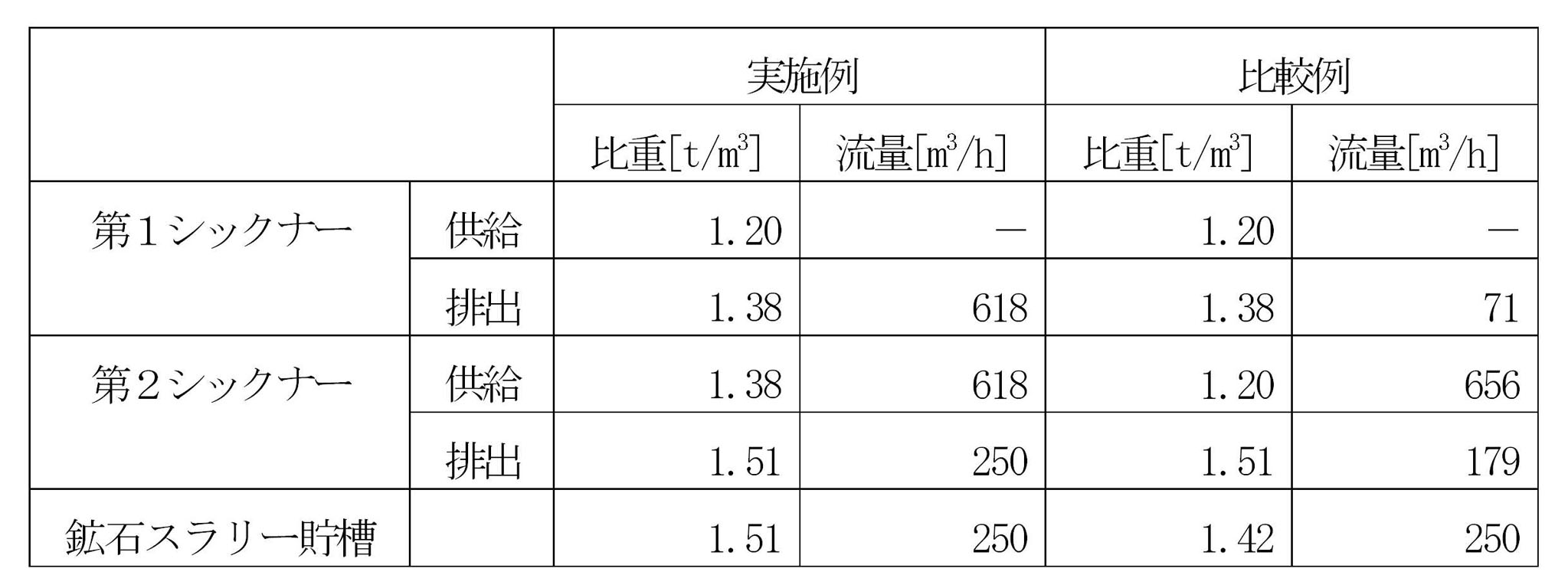
- ore slurry having a flow rate of 71 m 3 / h was obtained from the first thickener 101.
- the ore slurry storage tank 103 the ore slurry obtained from the first thickener 101 and the second thickener 102 was mixed to obtain an ore slurry having a specific gravity of 1.42 t / m 3 and a solid component ratio of 42%.
- a ore slurry manufacturing equipment 1 1st thickener 2 2nd thickener 3 Ore slurry storage tank
Landscapes
- Chemical & Material Sciences (AREA)
- Chemical Kinetics & Catalysis (AREA)
- Manufacture And Refinement Of Metals (AREA)
- Paper (AREA)
Abstract
Description
第2発明の鉱石スラリー製造設備は、第1発明において、前記第1シックナーには、前記中間鉱石スラリーの固体成分率が35~40%となるように凝集剤が添加されることを特徴とする。
第3発明の鉱石スラリー製造方法は、第1シックナーにより原料鉱石スラリーを予備濃縮して中間鉱石スラリーを得て、前記第1シックナーよりシックニング効果の高い第2シックナーにより前記中間鉱石スラリーを濃縮して濃縮鉱石スラリー得ることを特徴とする。
第4発明の鉱石スラリー製造方法は、第3発明において、前記第1シックナーに添加する凝集剤を前記中間鉱石スラリーの固体成分率が35~40%となるように調整することを特徴とする。
第2発明によれば、中間鉱石スラリーの固体成分率が35~40%であるので、第2シックナーにおいて鉱石スラリーの沈降速度が速くなり、スラリー処理量を増加できる。
第3発明によれば、第1シックナーで予備濃縮された中間鉱石スラリーが第2シックナーに供給されるので、第2シックナーにおいて鉱石スラリーの沈降速度が速くなり、第2シックナーの粒子沈降に要求される水面積を小さくすることができ、スラリー処理量を増加できる。また、後段がシックニング効果の高い第2シックナーであるので、固体成分率および比重の高い濃縮鉱石スラリーを製造できる。
第4発明によれば、中間鉱石スラリーの固体成分率が35~40%であるので、第2シックナーにおいて鉱石スラリーの沈降速度が速くなり、スラリー処理量を増加できる。
本発明の一実施形態に係る鉱石スラリー製造設備は、ニッケル酸化鉱石からニッケルを回収する高温加圧硫酸浸出法を用いた湿式製錬において、高温加圧硫酸浸出工程に送るニッケル酸化鉱石のスラリーを製造するのに用いられる。すなわち、鉱石スラリー製造設備は、ニッケル酸化鉱石を解砕分級してスラリー化したものを原料鉱石スラリーとし、その原料鉱石スラリーを目的の固体成分率および比重となるように濃縮して濃縮鉱石スラリーを製造する。
上記第1シックナー1と第2シックナー2を直列に接続した構成の鉱石スラリー製造設備(実施例)と、並列に接続した構成の鉱石スラリー製造設備(比較例)とを用いて鉱石スラリーを製造した。すなわち、実施例の鉱石スラリー製造設備は図1に示す上記実施形態に係る鉱石スラリー製造設備Aであり、比較例の鉱石スラリー製造設備は図4に示す従来構成の鉱石スラリー製造設備Bである。実施例における第1シックナー1と比較例における第1シックナー101とは同一のシックナーであり、同一のシックニング効果を有する。また、実施例における第2シックナー2と比較例における第2シックナー102とは同一のシックナーであり、同一のシックニング効果を有する。
上記実施例において、第1シックナー1に添加する凝集剤の添加量を調整して、中間鉱石スラリーの固体成分率を35~40%とした。また、実施例および比較例において、高温加圧硫酸浸出工程へのスラリー供給量が250m3/hとなるように操業を行った。実施例および比較例における各シックナーへの供給スラリー、排出スラリー、および鉱石スラリー貯槽内の鉱石スラリーの比重および流量を表1に示す。なお、原料鉱石スラリーの比重は1.20t/m3である。
1 第1シックナー
2 第2シックナー
3 鉱石スラリー貯槽
Claims (4)
- 原料鉱石スラリーを予備濃縮して中間鉱石スラリーを得る第1シックナーと、
前記中間鉱石スラリーを濃縮して濃縮鉱石スラリー得る、前記第1シックナーよりシックニング効果の高い第2シックナーと、を備える
ことを特徴とする鉱石スラリー製造設備。 - 前記第1シックナーには、前記中間鉱石スラリーの固体成分率が35~40%となるように凝集剤が添加される
ことを特徴とする請求項1記載の鉱石スラリー製造設備。 - 第1シックナーにより原料鉱石スラリーを予備濃縮して中間鉱石スラリーを得て、
前記第1シックナーよりシックニング効果の高い第2シックナーにより前記中間鉱石スラリーを濃縮して濃縮鉱石スラリー得る
ことを特徴とする鉱石スラリー製造方法。 - 前記第1シックナーに添加する凝集剤を前記中間鉱石スラリーの固体成分率が35~40%となるように調整する
ことを特徴とする請求項3記載の鉱石スラリー製造方法。
Priority Applications (5)
| Application Number | Priority Date | Filing Date | Title |
|---|---|---|---|
| EP14907542.6A EP3128018A4 (en) | 2014-12-05 | 2014-12-05 | Apparatus for producing ore slurry and process for producing ore slurry |
| PCT/JP2014/082196 WO2016088240A1 (ja) | 2014-12-05 | 2014-12-05 | 鉱石スラリー製造設備および鉱石スラリー製造方法 |
| AU2014413023A AU2014413023B2 (en) | 2014-12-05 | 2014-12-05 | Ore slurry manufacturing facility and ore slurry manufacturing method |
| CUP2017000076A CU20170076A7 (es) | 2014-12-05 | 2014-12-05 | Instalación de producción de pulpa mineral y método de producción de la pulpa mineral |
| PH12017500942A PH12017500942A1 (en) | 2014-12-05 | 2017-05-23 | Ore slurry manufacturing facility and ore slurry manufacturing method |
Applications Claiming Priority (1)
| Application Number | Priority Date | Filing Date | Title |
|---|---|---|---|
| PCT/JP2014/082196 WO2016088240A1 (ja) | 2014-12-05 | 2014-12-05 | 鉱石スラリー製造設備および鉱石スラリー製造方法 |
Publications (1)
| Publication Number | Publication Date |
|---|---|
| WO2016088240A1 true WO2016088240A1 (ja) | 2016-06-09 |
Family
ID=56091212
Family Applications (1)
| Application Number | Title | Priority Date | Filing Date |
|---|---|---|---|
| PCT/JP2014/082196 Ceased WO2016088240A1 (ja) | 2014-12-05 | 2014-12-05 | 鉱石スラリー製造設備および鉱石スラリー製造方法 |
Country Status (5)
| Country | Link |
|---|---|
| EP (1) | EP3128018A4 (ja) |
| AU (1) | AU2014413023B2 (ja) |
| CU (1) | CU20170076A7 (ja) |
| PH (1) | PH12017500942A1 (ja) |
| WO (1) | WO2016088240A1 (ja) |
Cited By (2)
| Publication number | Priority date | Publication date | Assignee | Title |
|---|---|---|---|---|
| WO2022138239A1 (ja) * | 2020-12-23 | 2022-06-30 | 住友金属鉱山株式会社 | 鉱石スラリーの製造方法、ニッケル酸化鉱石の湿式製錬方法 |
| JP7151848B1 (ja) | 2021-09-15 | 2022-10-12 | 住友金属鉱山株式会社 | クロム鉄鉱石の回収方法 |
Citations (4)
| Publication number | Priority date | Publication date | Assignee | Title |
|---|---|---|---|---|
| JP2000345250A (ja) * | 1999-06-04 | 2000-12-12 | Dowa Mining Co Ltd | 鉛製錬法 |
| JP2011225956A (ja) * | 2010-04-22 | 2011-11-10 | Sumitomo Metal Mining Co Ltd | 貯液装置及びその圧力制御方法 |
| US20130008856A1 (en) * | 2011-07-06 | 2013-01-10 | Cognis Ip Management Gmbh | Method For Controlling Solids/Liquid Decant Unit Operations And Systems |
| WO2013115161A1 (ja) * | 2012-02-01 | 2013-08-08 | 住友金属鉱山株式会社 | 鉱石スラリー製造工程におけるシックナー装置及びその固体成分率制御方法 |
Family Cites Families (2)
| Publication number | Priority date | Publication date | Assignee | Title |
|---|---|---|---|---|
| US20140150886A1 (en) * | 2012-11-30 | 2014-06-05 | Total E&P Canada Ltd. | Two-stage flocculation of fluid fine tailings |
| JP5644878B2 (ja) * | 2013-01-21 | 2014-12-24 | 住友金属鉱山株式会社 | 固液分離処理方法、並びにニッケル酸化鉱石の湿式製錬方法 |
-
2014
- 2014-12-05 AU AU2014413023A patent/AU2014413023B2/en not_active Ceased
- 2014-12-05 EP EP14907542.6A patent/EP3128018A4/en not_active Ceased
- 2014-12-05 WO PCT/JP2014/082196 patent/WO2016088240A1/ja not_active Ceased
- 2014-12-05 CU CUP2017000076A patent/CU20170076A7/xx unknown
-
2017
- 2017-05-23 PH PH12017500942A patent/PH12017500942A1/en unknown
Patent Citations (4)
| Publication number | Priority date | Publication date | Assignee | Title |
|---|---|---|---|---|
| JP2000345250A (ja) * | 1999-06-04 | 2000-12-12 | Dowa Mining Co Ltd | 鉛製錬法 |
| JP2011225956A (ja) * | 2010-04-22 | 2011-11-10 | Sumitomo Metal Mining Co Ltd | 貯液装置及びその圧力制御方法 |
| US20130008856A1 (en) * | 2011-07-06 | 2013-01-10 | Cognis Ip Management Gmbh | Method For Controlling Solids/Liquid Decant Unit Operations And Systems |
| WO2013115161A1 (ja) * | 2012-02-01 | 2013-08-08 | 住友金属鉱山株式会社 | 鉱石スラリー製造工程におけるシックナー装置及びその固体成分率制御方法 |
Non-Patent Citations (1)
| Title |
|---|
| See also references of EP3128018A4 * |
Cited By (5)
| Publication number | Priority date | Publication date | Assignee | Title |
|---|---|---|---|---|
| WO2022138239A1 (ja) * | 2020-12-23 | 2022-06-30 | 住友金属鉱山株式会社 | 鉱石スラリーの製造方法、ニッケル酸化鉱石の湿式製錬方法 |
| JP2022099597A (ja) * | 2020-12-23 | 2022-07-05 | 住友金属鉱山株式会社 | 鉱石スラリーの製造方法、ニッケル酸化鉱石の湿式製錬方法 |
| JP7127679B2 (ja) | 2020-12-23 | 2022-08-30 | 住友金属鉱山株式会社 | 鉱石スラリーの製造方法、ニッケル酸化鉱石の湿式製錬方法 |
| JP7151848B1 (ja) | 2021-09-15 | 2022-10-12 | 住友金属鉱山株式会社 | クロム鉄鉱石の回収方法 |
| JP2023042931A (ja) * | 2021-09-15 | 2023-03-28 | 住友金属鉱山株式会社 | クロム鉄鉱石の回収方法 |
Also Published As
| Publication number | Publication date |
|---|---|
| AU2014413023B2 (en) | 2017-06-22 |
| AU2014413023A1 (en) | 2016-10-27 |
| CU20170076A7 (es) | 2018-02-08 |
| EP3128018A1 (en) | 2017-02-08 |
| PH12017500942A1 (en) | 2017-11-20 |
| EP3128018A4 (en) | 2017-04-26 |
Similar Documents
| Publication | Publication Date | Title |
|---|---|---|
| JP5556608B2 (ja) | クロマイト回収方法、並びにニッケル酸化鉱石の湿式製錬方法 | |
| WO2013150642A1 (ja) | クロマイト回収方法、並びにニッケル酸化鉱石の湿式製錬方法 | |
| JP5360243B2 (ja) | 鉱石スラリー製造工程におけるシックナー装置及びその固体成分率制御方法 | |
| JP5971364B1 (ja) | 鉱石スラリーの前処理方法、鉱石スラリーの製造方法 | |
| JP6020651B1 (ja) | 鉱石スラリーの前処理方法、鉱石スラリーの製造方法 | |
| JP2019044208A (ja) | ニッケル酸化鉱石製錬における鉱石スラリー濃縮方法 | |
| JP5783223B2 (ja) | 鉱石スラリー製造設備および鉱石スラリー製造方法 | |
| JP5790839B2 (ja) | クロマイト回収方法 | |
| WO2016088240A1 (ja) | 鉱石スラリー製造設備および鉱石スラリー製造方法 | |
| JP5811297B1 (ja) | 鉱石スラリー製造設備および鉱石スラリー製造方法 | |
| CN107429316A (zh) | 镍硫化物的制造方法、镍氧化物矿的湿式冶炼方法 | |
| JP7220846B2 (ja) | 湿式製錬の原料として使用されるニッケル酸化鉱石の前処理方法 | |
| JP5692313B2 (ja) | 鉱石スラリー製造工程におけるシックナー装置及びその固体成分率制御方法 | |
| JP6977458B2 (ja) | ニッケル酸化鉱石の湿式製錬方法 | |
| JP7057900B2 (ja) | ニッケル酸化鉱石スラリーの前処理方法 | |
| JP6634870B2 (ja) | 塩化ニッケル水溶液の脱鉄方法 | |
| JP5896072B2 (ja) | 鉱石スラリー製造設備および鉱石スラリー製造方法 | |
| JP2021046572A5 (ja) | ||
| WO2018101069A1 (ja) | ニッケル酸化鉱石の湿式製錬方法 | |
| JP7127679B2 (ja) | 鉱石スラリーの製造方法、ニッケル酸化鉱石の湿式製錬方法 | |
| JP6981206B2 (ja) | 硫酸ニッケル水溶液の脱亜鉛システム、及びその方法 | |
| JP5786921B2 (ja) | 鉱石スラリー製造設備および鉱石スラリー製造方法 | |
| JP2020117749A (ja) | 鉱石スラリーの調製方法 | |
| JP7176595B1 (ja) | 鉱石スラリーの製造方法、ニッケル酸化鉱石の湿式製錬方法 | |
| JP2025012689A (ja) | ニッケル酸化鉱石スラリーの製造方法 |
Legal Events
| Date | Code | Title | Description |
|---|---|---|---|
| 121 | Ep: the epo has been informed by wipo that ep was designated in this application |
Ref document number: 14907542 Country of ref document: EP Kind code of ref document: A1 |
|
| ENP | Entry into the national phase |
Ref document number: 2014413023 Country of ref document: AU Date of ref document: 20141205 Kind code of ref document: A |
|
| REEP | Request for entry into the european phase |
Ref document number: 2014907542 Country of ref document: EP |
|
| WWE | Wipo information: entry into national phase |
Ref document number: 2014907542 Country of ref document: EP |
|
| NENP | Non-entry into the national phase |
Ref country code: DE |
|
| NENP | Non-entry into the national phase |
Ref country code: JP |