WO2016088459A1 - スピーカー装置 - Google Patents
スピーカー装置 Download PDFInfo
- Publication number
- WO2016088459A1 WO2016088459A1 PCT/JP2015/079416 JP2015079416W WO2016088459A1 WO 2016088459 A1 WO2016088459 A1 WO 2016088459A1 JP 2015079416 W JP2015079416 W JP 2015079416W WO 2016088459 A1 WO2016088459 A1 WO 2016088459A1
- Authority
- WO
- WIPO (PCT)
- Prior art keywords
- piezoelectric element
- coil bobbin
- diaphragm
- speaker device
- coil
- Prior art date
- Legal status (The legal status is an assumption and is not a legal conclusion. Google has not performed a legal analysis and makes no representation as to the accuracy of the status listed.)
- Ceased
Links
Images


Classifications
-
- H—ELECTRICITY
- H04—ELECTRIC COMMUNICATION TECHNIQUE
- H04R—LOUDSPEAKERS, MICROPHONES, GRAMOPHONE PICK-UPS OR LIKE ACOUSTIC ELECTROMECHANICAL TRANSDUCERS; ELECTRIC HEARING AIDS; PUBLIC ADDRESS SYSTEMS
- H04R1/00—Details of transducers, loudspeakers or microphones
- H04R1/20—Arrangements for obtaining desired frequency or directional characteristics
-
- H—ELECTRICITY
- H04—ELECTRIC COMMUNICATION TECHNIQUE
- H04R—LOUDSPEAKERS, MICROPHONES, GRAMOPHONE PICK-UPS OR LIKE ACOUSTIC ELECTROMECHANICAL TRANSDUCERS; ELECTRIC HEARING AIDS; PUBLIC ADDRESS SYSTEMS
- H04R17/00—Piezoelectric transducers; Electrostrictive transducers
-
- H—ELECTRICITY
- H04—ELECTRIC COMMUNICATION TECHNIQUE
- H04R—LOUDSPEAKERS, MICROPHONES, GRAMOPHONE PICK-UPS OR LIKE ACOUSTIC ELECTROMECHANICAL TRANSDUCERS; ELECTRIC HEARING AIDS; PUBLIC ADDRESS SYSTEMS
- H04R17/00—Piezoelectric transducers; Electrostrictive transducers
- H04R17/005—Piezoelectric transducers; Electrostrictive transducers using a piezoelectric polymer
-
- H—ELECTRICITY
- H04—ELECTRIC COMMUNICATION TECHNIQUE
- H04R—LOUDSPEAKERS, MICROPHONES, GRAMOPHONE PICK-UPS OR LIKE ACOUSTIC ELECTROMECHANICAL TRANSDUCERS; ELECTRIC HEARING AIDS; PUBLIC ADDRESS SYSTEMS
- H04R23/00—Transducers other than those covered by groups H04R9/00 - H04R21/00
- H04R23/02—Transducers using more than one principle simultaneously
-
- H—ELECTRICITY
- H04—ELECTRIC COMMUNICATION TECHNIQUE
- H04R—LOUDSPEAKERS, MICROPHONES, GRAMOPHONE PICK-UPS OR LIKE ACOUSTIC ELECTROMECHANICAL TRANSDUCERS; ELECTRIC HEARING AIDS; PUBLIC ADDRESS SYSTEMS
- H04R3/00—Circuits for transducers
- H04R3/02—Circuits for transducers for preventing acoustic reaction, i.e. acoustic oscillatory feedback
-
- H—ELECTRICITY
- H04—ELECTRIC COMMUNICATION TECHNIQUE
- H04R—LOUDSPEAKERS, MICROPHONES, GRAMOPHONE PICK-UPS OR LIKE ACOUSTIC ELECTROMECHANICAL TRANSDUCERS; ELECTRIC HEARING AIDS; PUBLIC ADDRESS SYSTEMS
- H04R9/00—Transducers of moving-coil, moving-strip, or moving-wire type
- H04R9/02—Details
- H04R9/025—Magnetic circuit
-
- H—ELECTRICITY
- H04—ELECTRIC COMMUNICATION TECHNIQUE
- H04R—LOUDSPEAKERS, MICROPHONES, GRAMOPHONE PICK-UPS OR LIKE ACOUSTIC ELECTROMECHANICAL TRANSDUCERS; ELECTRIC HEARING AIDS; PUBLIC ADDRESS SYSTEMS
- H04R9/00—Transducers of moving-coil, moving-strip, or moving-wire type
- H04R9/02—Details
- H04R9/04—Construction, mounting, or centering of coil
-
- H—ELECTRICITY
- H10—SEMICONDUCTOR DEVICES; ELECTRIC SOLID-STATE DEVICES NOT OTHERWISE PROVIDED FOR
- H10N—ELECTRIC SOLID-STATE DEVICES NOT OTHERWISE PROVIDED FOR
- H10N30/00—Piezoelectric or electrostrictive devices
- H10N30/20—Piezoelectric or electrostrictive devices with electrical input and mechanical output, e.g. functioning as actuators or vibrators
-
- H—ELECTRICITY
- H10—SEMICONDUCTOR DEVICES; ELECTRIC SOLID-STATE DEVICES NOT OTHERWISE PROVIDED FOR
- H10N—ELECTRIC SOLID-STATE DEVICES NOT OTHERWISE PROVIDED FOR
- H10N30/00—Piezoelectric or electrostrictive devices
- H10N30/50—Piezoelectric or electrostrictive devices having a stacked or multilayer structure
- H10N30/503—Piezoelectric or electrostrictive devices having a stacked or multilayer structure having a non-rectangular cross-section in a plane orthogonal to the stacking direction, e.g. polygonal or circular in top view
- H10N30/505—Piezoelectric or electrostrictive devices having a stacked or multilayer structure having a non-rectangular cross-section in a plane orthogonal to the stacking direction, e.g. polygonal or circular in top view the cross-section being annular
-
- H—ELECTRICITY
- H10—SEMICONDUCTOR DEVICES; ELECTRIC SOLID-STATE DEVICES NOT OTHERWISE PROVIDED FOR
- H10N—ELECTRIC SOLID-STATE DEVICES NOT OTHERWISE PROVIDED FOR
- H10N30/00—Piezoelectric or electrostrictive devices
- H10N30/50—Piezoelectric or electrostrictive devices having a stacked or multilayer structure
- H10N30/506—Piezoelectric or electrostrictive devices having a stacked or multilayer structure having a cylindrical shape and having stacking in the radial direction, e.g. coaxial or spiral type rolls
Definitions
- This technology relates to the technical field of a speaker device in which a magnetic circuit and a piezoelectric element are provided in a drive unit that vibrates a diaphragm.
- a speaker device that outputs the sound amplified by the amplifier.
- a speaker device for example, an apparatus configured such that a diaphragm is vibrated by a magnetic circuit constituted by a magnet, a yoke, and a coil, and the diaphragm is vibrated by expansion and contraction of a piezoelectric element. Yes (see, for example, Patent Document 1).
- the yoke is disposed so as to pass through the center of the annular magnet, and a cylindrical coil bobbin is disposed between the magnet and the yoke.
- a coil is wound around the outer peripheral surface of the coil bobbin, and the coil is disposed in a magnetic gap formed between the yoke and the magnet.
- the piezoelectric element is formed in a disk shape and is coupled to one end in the axial direction, which is the direction of fluctuation of the coil bobbin.
- the diaphragm is coupled to the center of the piezoelectric element.
- a drive current is supplied to the coil based on the audio signal output from the amplifier, the coil is changed integrally with the coil bobbin, and the diaphragm is changed along with the change of the coil bobbin. Vibrated.
- a current is supplied to the piezoelectric element based on the audio signal output from the amplifier, the piezoelectric element is expanded and contracted, and the diaphragm is vibrated even when the piezoelectric element varies. Therefore, the diaphragm is vibrated with fluctuations of both the coil bobbin and the piezoelectric element, and sound is output according to the vibration of the diaphragm.
- the diaphragm is connected to the coil bobbin via the piezoelectric element, and the driving force generated by the magnetic circuit is generated from the coil bobbin. It is transmitted to the diaphragm via the piezoelectric element.
- the speaker device may not be able to obtain a large amplitude and may not output a good sound. It is desired that the driving force generated by the circuit is transmitted to the diaphragm via the piezoelectric element without loss.
- the speaker device outputs a voice in a wide band without becoming a single-peak characteristic.
- a speaker device includes an annular coil bobbin that is at least partially disposed between a yoke and a magnet, a coil that is wound around the coil bobbin and supplied with a drive current and fluctuates with the coil bobbin, One end portion is coupled to one end portion in the fluctuation direction of the coil bobbin, and a piezoelectric element that is expanded and contracted by current supply and is changed in the same direction as the fluctuation direction, and an inner peripheral portion is coupled to the other end portion of the piezoelectric element.
- the coupling portion of the diaphragm with respect to the piezoelectric element and the coupling portion of the piezoelectric element with respect to the coil bobbin are positioned on a straight line in the variation direction.
- the driving force generated by the magnetic circuit is transmitted to the diaphragm through two coupling portions positioned on a straight line.
- the piezoelectric element is coupled to a part of the coil bobbin in the circumferential direction.
- the piezoelectric elements are provided, and the plurality of piezoelectric elements are arranged at regular intervals in the circumferential direction of the coil bobbin.
- the piezoelectric element is formed in an annular shape, and the piezoelectric element is coupled to the entire circumferential direction of the coil bobbin and the entire circumferential direction of the diaphragm.
- the initial movement time of the diaphragm when the drive current is supplied to the coil and the initial movement time of the diaphragm when a current is supplied to the piezoelectric element are approximately. It is desirable that time correction is performed so as to match.
- phase of the diaphragm when the drive current is supplied to the coil and the phase of the diaphragm when the current is supplied to the piezoelectric element are the same. It is desirable that phase correction is performed so that
- the driving force generated by the magnetic circuit is transmitted to the diaphragm via two coupling portions positioned on a straight line, the driving loss for the diaphragm is reduced and the sound in a wide band is reduced. A good output state can be ensured.
- FIG. 2 to 9 show an embodiment of the speaker device of the present technology, which is an enlarged cross-sectional view of the speaker device. It is a graph which shows an impulse response characteristic when driving for every coil drive part and a piezoelectric drive part. It is a graph which shows the phase characteristic for every coil drive part and a piezoelectric drive part. It is a block diagram which shows an example of the circuit provided with the correction control apparatus. It is a block diagram which shows another example of the circuit provided with the correction control apparatus. It is a graph which shows the characteristic before and after performing time correction and phase correction, and shows an impulse response characteristic. It is a graph which shows the characteristic before and after performing time correction and phase correction, and shows a frequency response characteristic.
- the direction in which the speaker device faces is the front, and the directions of up, down, front, back, left and right are shown.
- the speaker device 1 includes a frame 2 and each part attached to the frame 2 (see FIG. 1).
- the frame 2 includes a bottom surface portion 3 formed in an annular shape facing the front-rear direction, a peripheral surface portion 4 continuous to the outer peripheral portion of the bottom surface portion 3, and a flange-shaped mounting portion projecting outward from the front end portion of the peripheral surface portion 4. 5.
- a central hole of the bottom surface portion 3 is formed as an insertion hole 3a.
- the peripheral surface portion 4 is inclined so as to be displaced outward as it goes forward.
- a terminal (not shown) is attached to the outer surface of the peripheral surface portion 4 or the attachment portion 5.
- the terminal is provided as a terminal portion for connection with an amplifier (not shown).
- An annular magnet 6 is attached to the rear surface of the bottom surface portion 3.
- the magnet 6 has a center hole 6a smaller than the insertion hole 3a of the bottom surface portion 3, and the center axis of the center hole 6a and the insertion hole 3a are aligned.
- the yoke 7 is attached to the rear surface of the magnet 6.
- the yoke 7 is constituted by a main body yoke 8 and a connecting yoke 9.
- the main body yoke 8 is formed by integrally forming a disc-shaped base surface portion 10 facing in the front-rear direction and a round shaft-shaped insertion protrusion 11 protruding forward from the center portion of the base surface portion 10.
- the front end portion of the insertion protrusion 11 is inserted through the center hole 6 a of the magnet 6. Therefore, a space is formed between the inner peripheral surface of the magnet 6 and the outer peripheral surface of the insertion protrusion 11, and this space is formed as a magnetic gap.
- the connecting yoke 9 is formed in an annular shape, and its thickness is made smaller than the length of the insertion protrusion 11 in the axial direction.
- the connecting yoke 9 has a rear surface attached to an outer peripheral portion of the front surface of the base surface portion 10 and a front surface attached to an outer peripheral portion of the rear surface of the magnet 6.
- a part of the cylindrical coil bobbin 12 is disposed in the magnetic gap.
- the coil bobbin 12 is movable (movable) in the axial direction (front-rear direction) with respect to the insertion protrusion 11.
- a coil 13 is wound around the outer peripheral surface of the coil bobbin 12. The ends of both sides of the coil 13 are led out from the wound portion and connected to the terminal. A part of the coil 13 is disposed in the magnetic gap.
- the coil 13 By arranging the coil 13 in the magnetic gap, the coil 13, the magnet 6 and the yoke 7 constitute a magnetic circuit.
- the speaker device 1 may be provided with a damper that suppresses excessive fluctuation in the axial direction of the coil bobbin 12.
- the rear end portions of, for example, three piezoelectric elements 14, 14, 14 are coupled to the front end portion of the coil bobbin 12.
- the piezoelectric elements 14, 14, 14 are arranged, for example, at equal intervals in the circumferential direction of the coil bobbin 12 (in FIG. 1, the piezoelectric elements 14, 14 and 14).
- the number of piezoelectric elements 14 is arbitrary, and at least one piezoelectric element 14 may be provided. However, when a plurality of piezoelectric elements 14, 14,... Are provided, it is desirable that the piezoelectric elements 14, 14,.
- the piezoelectric element 14 is, for example, a stacked piezoelectric element formed in a shape extending in the front-rear direction and stacked in the front-rear direction.
- the piezoelectric element 14 may be a single layer, but it is desirable to use a laminated type in order to increase the amount of displacement (driving force).
- the fluctuation amount of the piezoelectric element 14 is increased even at a low voltage, and in particular, the high frequency characteristics can be improved.
- D33 type is used as the piezoelectric element 14.
- the d33 type As the piezoelectric element 14, a large driving force can be obtained in the fluctuation direction (front-rear direction), and the sound quality can be improved.
- the d33 type used as the piezoelectric element 14 has a characteristic that the displacement amount is the same regardless of the thickness in a single layer, and therefore, the miniaturization is ensured by forming a thin thickness and stacking. In addition, a large driving force can be secured. However, since the withstand voltage decreases when the thickness is reduced, it is desirable to set the thickness of the piezoelectric element 14 in consideration of the driving force and the withstand voltage.
- the d33 type since the d33 type generates a larger stress than the d31 type and does not easily have a single-peak characteristic, the use of the d33 type as the piezoelectric element 14 can secure a necessary sound pressure and improve a wide range characteristic. it can.
- the piezoelectric element 14 since the piezoelectric element 14 only needs to be formed in a simple shape such as a rectangular shape or a circular shape, the piezoelectric element 14 can be easily manufactured and the manufacturing cost can be reduced.
- An electric wire (not shown) is connected to the piezoelectric elements 14, 14, and 14, and the electric wire is connected to a terminal. A current is supplied to the piezoelectric elements 14, 14, 14 via electric wires.
- the outer peripheral part of the diaphragm 15 is attached to the attachment part 5 of the frame 2.
- the front end portions of the piezoelectric elements 14, 14, 14 are coupled to the inner peripheral portion of the vibration plate 15 at equal intervals in the circumferential direction. Therefore, each coupling portion of the diaphragm 15 with respect to the piezoelectric elements 14, 14, and 14 and each coupling portion of the piezoelectric elements 14, 14, and 14 with respect to the coil bobbin 12 are positioned on a straight line in the variation direction.
- the diaphragm 15 is vibrated so that the front end is a fulcrum with the fluctuation in the longitudinal direction of the coil bobbin 12 and the fluctuation in the longitudinal direction of the piezoelectric elements 14, 14, 14.
- the diaphragm 15 is vibrated with the fluctuation of the coil bobbin 12 by driving the magnetic circuit and is vibrated with the fluctuation accompanying expansion and contraction of the piezoelectric elements 14, 14, 14. Accordingly, the piezoelectric elements 14, 14, and 14 function as a part of the magnetic circuit and function as a drive unit that vibrates the diaphragm 15.
- a dome-shaped cap 16 is attached to the inner periphery of the diaphragm 15.
- the piezoelectric elements 14, 14, 14 are coupled to each part in the circumferential direction of the coil bobbin 12, the weight of the drive unit in the speaker device 1 is excessively large.
- the transient characteristics are improved and wide-band reproduction can be ensured, and good sound quality and sound pressure can be ensured.
- the piezoelectric elements 14, 14, 14 are arranged at equal intervals in the circumferential direction of the coil bobbin 12. Therefore, a good balance is ensured in the position of the piezoelectric elements 14, 14, 14 with respect to the coil bobbin 12, and driving force (driving energy) is transmitted from the coil bobbin 12 to the diaphragm 15 via the piezoelectric elements 14, 14, 14. Transmission of driving force (driving energy) from the piezoelectric elements 14, 14, and 14 to the diaphragm 15 is performed in a stable state, and driving loss can be reduced.
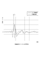
- FIG. 2 is a result showing an impulse response characteristic when driving is performed for each driving unit in the speaker device 1. Specifically, when the drive current is supplied to the coil 13 and the drive unit (coil drive unit) is operated, the drive unit (piezoelectric drive unit) is supplied with current supplied to the piezoelectric elements 14, 14, 14. It is a result shown by comparing with the state when operating. The drive current supplied to the coil 13 and the current supplied to the piezoelectric elements 14, 14, 14 are currents based on the same input signal.
- the horizontal axis indicates time, and the vertical axis indicates gain (sound pressure).
- a solid line indicates a state when the coil driving unit is driven, and a dotted line indicates a state when the piezoelectric driving unit is driven.
- FIG. 3 shows the phase characteristics of the diaphragm 15 for each drive unit in the speaker device 1. Specifically, it is a result of measuring the acceleration and the phase for each of the coil driving unit and the piezoelectric driving unit with a cross frequency of 7 KHz.
- the horizontal axis represents frequency
- the vertical axis represents acceleration or phase.
- the upper two graphs show the acceleration and phase of the coil drive unit, and the lower two graphs show the acceleration and phase of the piezoelectric drive unit.
- the speaker device 1 Based on the results of T time delay and phase inversion as described above, the speaker device 1 performs the following time correction and phase inversion control.
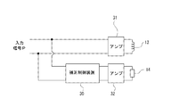
- the correction control device 30 is an arithmetic processing device such as a DSP (Digital Signal Processor), and controls to delay the operation time of the coil drive unit by T time with respect to the input signal and to invert the phase of the piezoelectric drive unit by 180 °. Execute.
- DSP Digital Signal Processor
- the input signal P is input to an amplifier 31 that sends a signal to the coil 13 and an amplifier 32 that sends a signal to the piezoelectric elements 14, 14, and 14.
- the input to the amplifier 32 is corrected in operation time and phase by the correction control device 30. It is done in the processed state. Therefore, a signal corrected by the correction control device 30 is input from the amplifier 32 to the piezoelectric elements 14, 14, 14.
- an LPF (low-pass filter) circuit 33 is incorporated in an input circuit for the amplifier 31 to extract a low frequency component and suppress a high frequency component.
- an HPF (High Pass Filter) circuit 34 may be incorporated in the input circuit to extract a high frequency component and suppress a low frequency component.
- FIG. 6 and 7 show the results of the characteristics before and after the time correction and the phase correction described above, FIG. 6 shows the impulse response characteristics, and FIG. 7 shows the frequency response characteristics.
- the horizontal axis indicates time, and the vertical axis indicates gain (sound pressure).
- the horizontal axis represents frequency, and the vertical axis represents gain (sound pressure). 6 and 7, the solid line shows the state after correction, and the dotted line shows the state before correction.
- the gain is particularly high at the peak time, and a good sound pressure is obtained. Also, as shown in FIG. 7, in the state where time correction and phase correction are performed, the gain is increased particularly in a high frequency region, and a good sound pressure is obtained.
- the coil driving unit and the piezoelectric driving unit are operated as one driving unit, and the quality of the output sound can be improved.
- phase correction is performed so that the phase of the diaphragm 15 when the drive current is supplied to the coil 13 and the phase of the diaphragm 15 when the current is supplied to the piezoelectric elements 14, 14, 14 are the same. It has been broken.
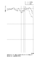
- FIG. 8 is a result showing frequency response characteristics in a high band for a conventional speaker device provided with only a coil drive unit and the speaker device 1 according to the present technology.
- the conventional speaker device has the same configuration as the speaker device 1 except for the piezoelectric elements 14, 14, and 14 as compared with the speaker device 1, and is formed of the same members and materials as the speaker device 1.
- the horizontal axis represents frequency and the vertical axis represents gain (sound pressure).
- the solid line indicates the state of the speaker device 1
- the dotted line indicates the state of the conventional speaker device.
- the speaker device 1 has a higher gain in a high band and a good sound pressure, and a good gain in a wide reproduction band as compared with a conventional speaker device. .
- one end portion is coupled to one end portion (front end portion) in the fluctuation direction (front-rear direction) of the coil bobbin 12, in the same direction as the fluctuation direction of the coil bobbin 12.
- bond part with respect to the coil bobbin 12 of the piezoelectric elements 14, 14, and 14 are located on the straight line in the fluctuation
- the driving force generated by the magnetic circuit is transmitted to the diaphragm 15 through the two joint portions positioned on a straight line, the driving loss for the diaphragm 15 is reduced and the sound in a wide band is excellent.
- the output state can be secured.
- the coupling portion of the piezoelectric elements 14, 14, 14 is positioned outside the central portion of the diaphragm 15, and the piezoelectric element having a configuration in which the frequency response characteristic is likely to be a single peak characteristic is the central portion of the diaphragm. Since it is not configured to be coupled, it is possible to ensure a good output state of sound in a wide band.
- the transient response characteristic is improved as compared with the case where only the coil bobbin 12 is used as the driving unit. Is possible.
- piezoelectric elements 14, 14, 14 extending in the front-rear direction (variation direction) and spaced apart in the circumferential direction are shown as an example.
- annular piezoelectric element 14A for example, may be used (see FIG. 9).
- the piezoelectric element 14 is formed in a single layer, for example.
- the piezoelectric element 14 ⁇ / b> A may be a stacked type that is stacked in the front-rear direction as in the piezoelectric element 14.
- the piezoelectric element 14 ⁇ / b> A has a rear surface that is one end coupled to the entire circumference of the front end of the coil bobbin 12, and a front surface that is the other end coupled to the entire circumference of the inner circumferential portion of the diaphragm 15. Accordingly, the coupling portion of the diaphragm 15 to the piezoelectric element 14A and the coupling portion of the piezoelectric element 14A to the coil bobbin 12 are positioned on a straight line in the variation direction.
- the d33 type is used as in the piezoelectric element 14.
- the annularly formed piezoelectric element 14A is coupled to the entirety of the coil bobbin 12 in the circumferential direction, a good balance of the position of the piezoelectric element 14A with respect to the coil bobbin 12 and the diaphragm 15 is ensured.
- the Accordingly, the transmission of the driving force (driving energy) from the coil bobbin 12 to the diaphragm 15 via the piezoelectric element 14A and the transmission of the driving force (driving energy) from the piezoelectric element 14A to the diaphragm 15 are stable. As a result, the drive loss can be reduced.
- the present technology can be configured as follows.
- An annular coil bobbin at least partially disposed between the yoke and the magnet; A coil wound around the coil bobbin and supplied with a drive current and fluctuated with the coil bobbin; One end is coupled to one end in the fluctuation direction of the coil bobbin and a current is supplied to expand and contract the piezoelectric element to be changed in the same direction as the fluctuation direction.
- a vibration plate having an inner peripheral portion coupled to the other end of the piezoelectric element;
- a speaker device in which a coupling portion of the diaphragm to the piezoelectric element and a coupling portion of the piezoelectric element to the coil bobbin are positioned on a straight line in the variation direction.
- a plurality of the piezoelectric elements are provided, The speaker device according to (2), wherein the plurality of piezoelectric elements are arranged at regular intervals in a circumferential direction of the coil bobbin.
- the piezoelectric element is formed in an annular shape, The speaker device according to any one of (1) to (3), wherein the piezoelectric element is coupled to the entire circumferential direction of the coil bobbin and the entire circumferential direction of the diaphragm.
- Time correction is performed so that the initial movement time of the diaphragm when the drive current is supplied to the coil and the initial movement time of the diaphragm when a current is supplied to the piezoelectric element are substantially the same.
- the speaker device according to any one of (1) to (5).
- Phase correction is performed so that the phase of the diaphragm when the drive current is supplied to the coil and the phase of the diaphragm when the current is supplied to the piezoelectric element are the same (1
- the speaker device according to any one of (6) to (6).
Landscapes
- Physics & Mathematics (AREA)
- Engineering & Computer Science (AREA)
- Acoustics & Sound (AREA)
- Signal Processing (AREA)
- Health & Medical Sciences (AREA)
- General Health & Medical Sciences (AREA)
- Otolaryngology (AREA)
- Circuit For Audible Band Transducer (AREA)
- Piezo-Electric Transducers For Audible Bands (AREA)
- Electrostatic, Electromagnetic, Magneto- Strictive, And Variable-Resistance Transducers (AREA)
- Audible-Bandwidth Dynamoelectric Transducers Other Than Pickups (AREA)
Abstract
Description
スピーカー装置1はフレーム2とフレーム2に取り付けられた各部とを有する(図1参照)。
上記のように構成されたスピーカー装置1において、コイル13に駆動電流が供給されると、磁気回路において推力が発生してコイルボビン12が前後方向(軸方向)へ変動され、コイルボビン12の駆動力(駆動エネルギー)が圧電素子14、14、14を介して振動板15に伝達されコイルボビン12の変動に伴って振動板15が振動する。このとき同時に圧電素子14、14、14に電流が供給され、圧電素子14、14、14がそれぞれ伸縮されて前後方向へ変動され圧電素子14、14、14の変動に伴っても振動板15が振動する。振動板15が振動するとアンプによって増幅された音声の出力が行われる。
以下に、スピーカー装置1の動作時における制御について説明する(図2乃至図7参照)。
図8は、コイル駆動部のみが設けられた従来のスピーカー装置と本技術に係るスピーカー装置1とについての高帯域における周波数応答特性を示す結果である。尚、従来のスピーカー装置はスピーカー装置1と比較して、圧電素子14、14、14以外の構成がスピーカー装置1と同様であり、スピーカー装置1と同一の部材や材料によって形成されている。
上記には、前後方向(変動方向)に延び周方向に離隔して配置された圧電素子14、14、14を例として示したが、スピーカー装置1においては、圧電素子14、14、14に代えて環状、例えば、円環状の圧電素子14Aが用いられていてもよい(図9参照)。
上記には、前側から順に振動板15と圧電素子14、14Aとコイルボビン12が位置された例を示したが、振動板15と圧電素子14、14Aとコイルボビン12の位置関係は、例えば、前側から順に振動板15とコイルボビン12と圧電素子14、14Aが位置される構成であってもよい。
本技術は、以下のような構成にすることができる。
少なくとも一部がヨークとマグネットの間に配置された環状のコイルボビンと、
前記コイルボビンに巻き付けられ駆動電流が供給されて前記コイルボビンとともに変動されるコイルと、
一端部が前記コイルボビンの変動方向における一端部に結合されると共に電流が供給されて伸縮され前記変動方向と同じ方向へ変動される圧電素子と、
内周部が前記圧電素子の他端部に結合された振動板とを備え、
前記振動板の前記圧電素子に対する結合部分と前記圧電素子の前記コイルボビンに対する結合部分とが前記変動方向において一直線上に位置された
スピーカー装置。
前記圧電素子が前記コイルボビンの周方向における一部に結合された
前記(1)に記載のスピーカー装置。
前記圧電素子が複数設けられ、
前記複数の圧電素子が前記コイルボビンの周方向において等間隔に離隔して配置された
前記(2)に記載のスピーカー装置。
前記圧電素子が環状に形成され、
前記圧電素子が前記コイルボビンの周方向における全体と前記振動板の周方向における全体とに結合された
前記(1)から前記(3)の何れかに記載のスピーカー装置。
前記圧電素子として前記変動方向において積層された積層型の圧電素子が用いられた
前記(1)から前記(4)の何れかに記載のスピーカー装置。
前記コイルに前記駆動電流が供給されたときの前記振動板の初動時間と前記圧電素子に電流が供給されたときの前記振動板の初動時間とが略一致されるように時間補正が行われる
前記(1)から前記(5)の何れかに記載のスピーカー装置。
前記コイルに前記駆動電流が供給されたときの前記振動板における位相と前記圧電素子に前記電流が供給されたときの前記振動板における位相とが同じになるように位相補正が行われる
前記(1)から前記(6)の何れかに記載のスピーカー装置。
前記圧電素子としてd33型の圧電素子が用いられた
前記(1)から前記(7)の何れかに記載のスピーカー装置。
Claims (8)
- 少なくとも一部がヨークとマグネットの間に配置された環状のコイルボビンと、
前記コイルボビンに巻き付けられ駆動電流が供給されて前記コイルボビンとともに変動されるコイルと、
一端部が前記コイルボビンの変動方向における一端部に結合されると共に電流が供給されて伸縮され前記変動方向と同じ方向へ変動される圧電素子と、
内周部が前記圧電素子の他端部に結合された振動板とを備え、
前記振動板の前記圧電素子に対する結合部分と前記圧電素子の前記コイルボビンに対する結合部分とが前記変動方向において一直線上に位置された
スピーカー装置。 - 前記圧電素子が前記コイルボビンの周方向における一部に結合された
請求項1に記載のスピーカー装置。 - 前記圧電素子が複数設けられ、
前記複数の圧電素子が前記コイルボビンの周方向において等間隔に離隔して配置された
請求項2に記載のスピーカー装置。 - 前記圧電素子が環状に形成され、
前記圧電素子が前記コイルボビンの周方向における全体と前記振動板の周方向における全体とに結合された
請求項1に記載のスピーカー装置。 - 前記圧電素子として前記変動方向において積層された積層型の圧電素子が用いられた
請求項1に記載のスピーカー装置。 - 前記コイルに前記駆動電流が供給されたときの振動板の初動時間と前記圧電素子に電流が供給されたときの前記振動板の初動時間とが略一致されるように時間補正が行われる
請求項1に記載のスピーカー装置。 - 前記コイルに前記駆動電流が供給されたときの前記振動板における位相と前記圧電素子に前記電流が供給されたときの前記振動板における位相とが同じになるように位相補正が行われる
請求項1に記載のスピーカー装置。 - 前記圧電素子としてd33型の圧電素子が用いられた
請求項1に記載のスピーカー装置。
Priority Applications (4)
| Application Number | Priority Date | Filing Date | Title |
|---|---|---|---|
| JP2016562341A JP6614158B2 (ja) | 2014-12-02 | 2015-10-19 | スピーカー装置 |
| CN201580051596.0A CN107079225B (zh) | 2014-12-02 | 2015-10-19 | 扬声器装置 |
| EP15864616.6A EP3185582B1 (en) | 2014-12-02 | 2015-10-19 | Speaker device |
| US15/512,060 US10154336B2 (en) | 2014-12-02 | 2015-10-19 | Speaker apparatus |
Applications Claiming Priority (2)
| Application Number | Priority Date | Filing Date | Title |
|---|---|---|---|
| JP2014-244202 | 2014-12-02 | ||
| JP2014244202 | 2014-12-02 |
Publications (1)
| Publication Number | Publication Date |
|---|---|
| WO2016088459A1 true WO2016088459A1 (ja) | 2016-06-09 |
Family
ID=56091415
Family Applications (1)
| Application Number | Title | Priority Date | Filing Date |
|---|---|---|---|
| PCT/JP2015/079416 Ceased WO2016088459A1 (ja) | 2014-12-02 | 2015-10-19 | スピーカー装置 |
Country Status (5)
| Country | Link |
|---|---|
| US (1) | US10154336B2 (ja) |
| EP (1) | EP3185582B1 (ja) |
| JP (1) | JP6614158B2 (ja) |
| CN (1) | CN107079225B (ja) |
| WO (1) | WO2016088459A1 (ja) |
Families Citing this family (2)
| Publication number | Priority date | Publication date | Assignee | Title |
|---|---|---|---|---|
| US11462199B2 (en) * | 2018-02-21 | 2022-10-04 | Em-Tech. Co., Ltd. | Hybrid actuator and multimedia apparatus having the same |
| GB2597988B (en) | 2020-08-13 | 2024-11-06 | Full Stack Acoustic Ltd | Loudspeaker apparatus, Loudspeaker system, display panel and systems thereof |
Citations (4)
| Publication number | Priority date | Publication date | Assignee | Title |
|---|---|---|---|---|
| JPS59112799A (ja) * | 1982-12-18 | 1984-06-29 | Matsushita Electric Ind Co Ltd | スピ−カ |
| JPH09322286A (ja) * | 1996-05-31 | 1997-12-12 | Sony Corp | スピーカ装置および音響再生システム |
| WO2005067346A1 (ja) * | 2003-12-26 | 2005-07-21 | Nec Corporation | 圧電アクチュエータ |
| JP2014068342A (ja) * | 2012-09-07 | 2014-04-17 | Shinichiro Nakaishi | 難聴者支援スピーカ |
Family Cites Families (13)
| Publication number | Priority date | Publication date | Assignee | Title |
|---|---|---|---|---|
| US3588381A (en) * | 1967-08-28 | 1971-06-28 | Motorola Inc | Transducer having spaced apart oppositely flexing piezoelectric members |
| NL7308103A (ja) * | 1973-06-12 | 1974-12-16 | ||
| JPS5591299A (en) * | 1978-12-29 | 1980-07-10 | Sony Corp | Electroacoustic converter |
| JPS58176500U (ja) * | 1982-05-20 | 1983-11-25 | 三洋電機株式会社 | スピ−カ |
| US4727586A (en) * | 1986-07-14 | 1988-02-23 | Johnson Charles A | High fidelity speaker system and assembly |
| JPH0723384Y2 (ja) | 1987-07-23 | 1995-05-31 | ソニー株式会社 | 包装箱 |
| US5062139A (en) * | 1989-06-05 | 1991-10-29 | Christensen Eugene J | Coaxial loud speaker system |
| US5126618A (en) * | 1990-03-06 | 1992-06-30 | Brother Kogyo Kabushiki Kaisha | Longitudinal-effect type laminar piezoelectric/electrostrictive driver, and printing actuator using the driver |
| JP3136853B2 (ja) * | 1993-08-16 | 2001-02-19 | ソニー株式会社 | スピーカユニット |
| JP2000078691A (ja) * | 1998-08-26 | 2000-03-14 | Tohoku Pioneer Corp | スピーカ装置 |
| EP1585363A3 (en) * | 2004-02-24 | 2006-01-18 | VIBRATION-X di Bianchini Emanuele e C. Sas | Improved audio frequency speaker |
| US9084051B2 (en) * | 2011-02-18 | 2015-07-14 | The Rockefeller University | Unidirectional mechanical amplification in a microphone |
| JP2015091069A (ja) * | 2013-11-07 | 2015-05-11 | 株式会社村田製作所 | 圧電スピーカ |
-
2015
- 2015-10-19 CN CN201580051596.0A patent/CN107079225B/zh not_active Expired - Fee Related
- 2015-10-19 WO PCT/JP2015/079416 patent/WO2016088459A1/ja not_active Ceased
- 2015-10-19 JP JP2016562341A patent/JP6614158B2/ja not_active Expired - Fee Related
- 2015-10-19 EP EP15864616.6A patent/EP3185582B1/en not_active Not-in-force
- 2015-10-19 US US15/512,060 patent/US10154336B2/en active Active
Patent Citations (4)
| Publication number | Priority date | Publication date | Assignee | Title |
|---|---|---|---|---|
| JPS59112799A (ja) * | 1982-12-18 | 1984-06-29 | Matsushita Electric Ind Co Ltd | スピ−カ |
| JPH09322286A (ja) * | 1996-05-31 | 1997-12-12 | Sony Corp | スピーカ装置および音響再生システム |
| WO2005067346A1 (ja) * | 2003-12-26 | 2005-07-21 | Nec Corporation | 圧電アクチュエータ |
| JP2014068342A (ja) * | 2012-09-07 | 2014-04-17 | Shinichiro Nakaishi | 難聴者支援スピーカ |
Non-Patent Citations (1)
| Title |
|---|
| See also references of EP3185582A4 * |
Also Published As
| Publication number | Publication date |
|---|---|
| US20170295423A1 (en) | 2017-10-12 |
| JP6614158B2 (ja) | 2019-12-04 |
| CN107079225A (zh) | 2017-08-18 |
| EP3185582A1 (en) | 2017-06-28 |
| JPWO2016088459A1 (ja) | 2017-09-07 |
| EP3185582B1 (en) | 2019-10-09 |
| EP3185582A4 (en) | 2018-03-14 |
| CN107079225B (zh) | 2019-12-10 |
| US10154336B2 (en) | 2018-12-11 |
Similar Documents
| Publication | Publication Date | Title |
|---|---|---|
| US20090208039A1 (en) | Hybrid actuator, loudspeaker and sound output method | |
| KR101814951B1 (ko) | 스피커 및 이어폰 | |
| US20170085979A1 (en) | Electroacoustic Transducer | |
| KR101584651B1 (ko) | 슬림형 스피커 및 그의 제조 방법 | |
| US10142736B2 (en) | Electroacoustic transducer | |
| US20180098155A1 (en) | Electroacoustic transducer | |
| US20110116662A1 (en) | Speaker device | |
| JP6614158B2 (ja) | スピーカー装置 | |
| US11057710B2 (en) | Loudspeaker structure | |
| JP5650079B2 (ja) | ダイナミックマイクロホンユニットおよびダイナミックマイクロホン | |
| JP6548931B2 (ja) | ダイナミックスピーカ装置 | |
| JP2012080480A (ja) | スピーカーユニット及びアクティブスピーカー装置 | |
| JP6482004B2 (ja) | スピーカ | |
| JP6206906B2 (ja) | ダイナミックマイクロホンユニットおよびダイナミックマイクロホン | |
| WO2019102860A1 (ja) | 振動板、およびこの振動板を有する電気音響変換器 | |
| CN106537936B (zh) | 电动式声变换器 | |
| CN101310559A (zh) | 扬声器 | |
| JP2005341223A (ja) | スピーカ | |
| JP2014003470A (ja) | スピーカ装置 | |
| JP2010114734A (ja) | スピーカ | |
| WO2017038301A1 (ja) | スピーカー装置及びスピーカー装置のフレーム | |
| WO2016051744A1 (ja) | 磁気回路と、これを用いたラウドスピーカ | |
| JP2005094448A (ja) | 音響放射装置用電磁変換装置及び音響放射装置 | |
| JP4154347B2 (ja) | スピーカの磁気回路 | |
| JP4592382B2 (ja) | スピーカ |
Legal Events
| Date | Code | Title | Description |
|---|---|---|---|
| 121 | Ep: the epo has been informed by wipo that ep was designated in this application |
Ref document number: 15864616 Country of ref document: EP Kind code of ref document: A1 |
|
| REEP | Request for entry into the european phase |
Ref document number: 2015864616 Country of ref document: EP |
|
| WWE | Wipo information: entry into national phase |
Ref document number: 2015864616 Country of ref document: EP |
|
| WWE | Wipo information: entry into national phase |
Ref document number: 15512060 Country of ref document: US |
|
| ENP | Entry into the national phase |
Ref document number: 2016562341 Country of ref document: JP Kind code of ref document: A |
|
| NENP | Non-entry into the national phase |
Ref country code: DE |