WO2016088473A1 - 接続構造および医療機器 - Google Patents
接続構造および医療機器 Download PDFInfo
- Publication number
- WO2016088473A1 WO2016088473A1 PCT/JP2015/080193 JP2015080193W WO2016088473A1 WO 2016088473 A1 WO2016088473 A1 WO 2016088473A1 JP 2015080193 W JP2015080193 W JP 2015080193W WO 2016088473 A1 WO2016088473 A1 WO 2016088473A1
- Authority
- WO
- WIPO (PCT)
- Prior art keywords
- plug
- side device
- connection structure
- distal
- receptacle
- Prior art date
- Legal status (The legal status is an assumption and is not a legal conclusion. Google has not performed a legal analysis and makes no representation as to the accuracy of the status listed.)
- Ceased
Links
Images



Classifications
-
- A—HUMAN NECESSITIES
- A61—MEDICAL OR VETERINARY SCIENCE; HYGIENE
- A61B—DIAGNOSIS; SURGERY; IDENTIFICATION
- A61B1/00—Instruments for performing medical examinations of the interior of cavities or tubes of the body by visual or photographical inspection, e.g. endoscopes; Illuminating arrangements therefor
- A61B1/00112—Connection or coupling means
- A61B1/00121—Connectors, fasteners and adapters, e.g. on the endoscope handle
- A61B1/00124—Connectors, fasteners and adapters, e.g. on the endoscope handle electrical, e.g. electrical plug-and-socket connection
-
- A—HUMAN NECESSITIES
- A61—MEDICAL OR VETERINARY SCIENCE; HYGIENE
- A61B—DIAGNOSIS; SURGERY; IDENTIFICATION
- A61B1/00—Instruments for performing medical examinations of the interior of cavities or tubes of the body by visual or photographical inspection, e.g. endoscopes; Illuminating arrangements therefor
- A61B1/00112—Connection or coupling means
- A61B1/00121—Connectors, fasteners and adapters, e.g. on the endoscope handle
- A61B1/00126—Connectors, fasteners and adapters, e.g. on the endoscope handle optical, e.g. for light supply cables
-
- A—HUMAN NECESSITIES
- A61—MEDICAL OR VETERINARY SCIENCE; HYGIENE
- A61B—DIAGNOSIS; SURGERY; IDENTIFICATION
- A61B1/00—Instruments for performing medical examinations of the interior of cavities or tubes of the body by visual or photographical inspection, e.g. endoscopes; Illuminating arrangements therefor
- A61B1/04—Instruments for performing medical examinations of the interior of cavities or tubes of the body by visual or photographical inspection, e.g. endoscopes; Illuminating arrangements therefor combined with photographic or television appliances
-
- H—ELECTRICITY
- H01—ELECTRIC ELEMENTS
- H01R—ELECTRICALLY-CONDUCTIVE CONNECTIONS; STRUCTURAL ASSOCIATIONS OF A PLURALITY OF MUTUALLY-INSULATED ELECTRICAL CONNECTING ELEMENTS; COUPLING DEVICES; CURRENT COLLECTORS
- H01R13/00—Details of coupling devices of the kinds covered by groups H01R12/70 or H01R24/00 - H01R33/00
- H01R13/62—Means for facilitating engagement or disengagement of coupling parts or for holding them in engagement
- H01R13/6205—Two-part coupling devices held in engagement by a magnet
-
- G—PHYSICS
- G02—OPTICS
- G02B—OPTICAL ELEMENTS, SYSTEMS OR APPARATUS
- G02B23/00—Telescopes, e.g. binoculars; Periscopes; Instruments for viewing the inside of hollow bodies; Viewfinders; Optical aiming or sighting devices
- G02B23/24—Instruments or systems for viewing the inside of hollow bodies, e.g. fibrescopes
-
- H—ELECTRICITY
- H01—ELECTRIC ELEMENTS
- H01R—ELECTRICALLY-CONDUCTIVE CONNECTIONS; STRUCTURAL ASSOCIATIONS OF A PLURALITY OF MUTUALLY-INSULATED ELECTRICAL CONNECTING ELEMENTS; COUPLING DEVICES; CURRENT COLLECTORS
- H01R2201/00—Connectors or connections adapted for particular applications
- H01R2201/12—Connectors or connections adapted for particular applications for medicine and surgery
Definitions
- connection structure that connects a distal-side device and a proximal-side device included in a medical device, and a medical device that includes the connection structure.
- an electrical shield is provided on the outer periphery of a cable connecting an endoscope (front end side device), a processor, and a light source device (base end side device) of an endoscope system, and a cable connector.
- an endoscope front end side device
- a processor central processing unit
- a light source device base end side device
- the patient circuit included in the distal-side device that is in contact with or inserted into the object to be observed and the functional device included in the proximal-side device to ensure the safety of the operator of the medical device It is necessary to electrically insulate the ground circuit such as the primary circuit and the secondary circuit that are grounded by the protective ground. Therefore, in the above-described medical device, it is necessary to secure a spatial distance and a creepage distance for insulation between the distal side device and the proximal side device. If a clearance and creepage distance are secured between the distal device and the proximal device, radiation noise generated in the proximal device leaks to the outside from the gap between both devices, or disturbance noise is generated on the proximal side. There was a risk of entering the inside of the device.
- the present disclosure has been made in view of the above, and in a medical device including a distal-side device that is in contact with or inserted into an object to be observed and a proximal-side device connected to the distal-side device, It is an object of the present invention to provide a connection structure that can prevent leakage noise generated in a side device from leaking outside and disturbance noise from entering the base side device, and a medical device including the connection structure.
- a connection structure includes a distal-side device that is in contact with or inserted into an object to be observed, and an exterior body that is connected to the distal-side device and is grounded.
- connection structure may be characterized in that, in the connection structure, the magnetic body is provided in an exterior body of the plug.
- connection structure according to the present disclosure may be characterized in that, in the connection structure described above, the magnetic body is provided on an inner peripheral side with respect to an exterior body of the plug.
- connection structure may be characterized in that, in the connection structure, the magnetic body is provided in the receptacle.
- a medical device according to the present disclosure includes the above connection structure.
- the distal-end-side device is an endoscope that is inserted into the observed object and acquires information on the observed object.
- the distal-side device may be a control device that controls the distal-side device and processes information received from the distal-side device and / or a light source device that generates illumination light that irradiates the object to be observed. .
- At least one of the plug and the receptacle has a non-conductive magnetic body in a portion that crosses the opening formed in the exterior body of the proximal-side device in a state where the plug is inserted into the receptacle. Therefore, the space distance and the creepage distance are ensured by filling the gap between the distal end side device and the proximal end side device with the magnetic material. Therefore, it is possible to prevent leakage of radiation noise generated in the proximal side device to the outside and intrusion of disturbance noise into the proximal side device.
- FIG. 1 is a diagram illustrating a schematic configuration of an endoscope system that is a medical device according to an embodiment of the present disclosure.
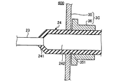
- FIG. 2 is a partial cross-sectional view schematically showing a configuration of a main part of the connection structure according to the embodiment of the present disclosure.
- FIG. 3 is a partial cross-sectional view schematically illustrating the configuration of the main part of the connection structure according to Modification 1 of the embodiment of the present disclosure.
- FIG. 4 is a partial cross-sectional view schematically showing the configuration of the main part of the connection structure according to Modification 2 of the embodiment of the present disclosure.
- FIG. 5 is a partial cross-sectional view schematically showing the configuration of the main part of the connection structure according to Modification 3 of the embodiment of the present disclosure.
- FIG. 1 is a diagram illustrating a schematic configuration of an endoscope system that is a medical device according to an embodiment of the present disclosure.
- FIG. 2 is a partial cross-sectional view schematically showing a configuration of a main part
- FIG. 6 is a partial cross-sectional view schematically showing the configuration of the main part of the connection structure according to Modification 4 of the embodiment of the present disclosure.
- FIG. 7 is a partial cross-sectional view schematically illustrating the configuration of the main part of the connection structure according to Modification 5 of the embodiment of the present disclosure.
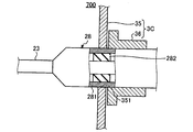
- FIG. 8 is a partial cross-sectional view schematically showing the configuration of the main part of the connection structure according to Modification 6 of the embodiment of the present disclosure.
- FIG. 9 is a partial cross-sectional view schematically showing a configuration of a main part of a connection structure according to another embodiment of the present disclosure.
- FIG. 1 is a diagram illustrating a schematic configuration of an endoscope system that is a medical device according to an embodiment of the present disclosure.
- An endoscope system 1 shown in FIG. 1 includes an endoscope 2 as a distal-end device that captures an in-vivo image of the observed object by inserting the distal end portion into the observed object, and the endoscope 2.
- a proximal-side device that performs predetermined image processing on the in-vivo image captured by the endoscope 2 to generate image data for display and controls the overall operation of the endoscope system 1
- Display device which has a display panel made of liquid crystal or organic EL (Electro Luminescence), and a light source device 4 that generates illumination light that irradiates the object to be observed from the distal end of the endoscope 2 And a device 5.
- the endoscope 2 is hard and has an elongated shape, and a distal end portion is detachably connected to the base end of the insertion portion 21 and an insertion portion 21 to be inserted into the observed body.
- a camera head 22 that captures an image of a lighted object to be observed and outputs an imaging signal
- a cable 23 that transmits an imaging signal output from the camera head 22 to the control device 3, and a base end portion of the cable 23.
- the plug 24 is a male connector that is detachably attached to the control device 3, and a light guide 25 that transmits illumination light generated by the light source device 4 to the distal end portion of the insertion portion 21.
- the insertion portion 21 is provided inside a cylindrical exterior body, and is provided inside the exterior body and a condensing optical system that condenses light from the object to be observed. And an illumination optical system for irradiating the object to be observed with illumination light transmitted through the device.
- the condensing optical system and the illumination optical system are each configured by using one or a plurality of lenses.
- the camera head 22 includes an image sensor that photoelectrically converts light collected by the optical system of the insertion unit 21 to generate an image signal, and an input unit that receives an input of an operation instruction signal of the endoscope 2.
- the image sensor is configured using an image sensor such as a CCD (Charge Coupled Device) or a CMOS (Complementary Metal Oxide Semiconductor).
- FIG. 2 is a partial cross-sectional view showing a state in which the plug 24 is inserted into a receptacle 32 (described later) which is a female connector provided in the control device 3.
- the plug 24 is provided inside the outer body 241 configured using a non-conductive magnetic body, and inside the plug on the inner peripheral side of the outer body 241. It has a metal shield body 242 that receives the distal end portion and is connected to a reference potential (patient ground) of a patient circuit included in the endoscope 2.
- the outer package 241 of the plug 24 crosses the opening 311 formed in the main body 31 of the control device 3.
- magnetic powder such as ferrite, neodymium, and samarium cobalt is mixed with various non-conductive resins such as polyamide (nylon) and polyphenylene sulfide, and injection molded. It is possible to apply a material processed into a plate shape or a cylindrical shape. It is also possible to use a magnetic material powder such as ferrite, neodymium, and samarium cobalt kneaded with non-conductive rubber.
- a magnetic polymer PANiCNQ
- TCNQ electron acceptor tetracyanoquinodimethane
- TCNQ electron acceptor tetracyanoquinodimethane
- TCNQ electron acceptor tetracyanoquinodimethane
- TCNQ electron acceptor tetracyanoquinodimethane
- TCNQ electron acceptor tetracyanoquinodimethane
- TCNQ electron acceptor tetracyanoquinodimethane
- PANi emeraldine-based polyaniline
- the exterior body 241 is preferably configured using a material having a wide band and high magnetic permeability. For example, it is preferable to use a material having a band of 30 MHz or more and a permeability of 100 H / m or more. Note that the material of the exterior body 241 is not limited to the above-described material, and is a material according to the environment to be used, which affects the peripheral device used in combination with the endoscope 2 or causes noise from the peripheral device. What is necessary is just to set suitably the material which is not influenced.
- the control device 3 includes a main body 31 having a housing shape, and a receptacle 32 that is attached to the opening 311 of the main body 31 and is a cylindrical female connector that is detachably inserted and held. Have. As shown in FIG. 2, the receptacle 32 crosses the opening 311 of the main body 31 of the control device 3.
- the main body 31 is configured using a metal or an alloy.
- the main body 31 is electrically insulated from the patient circuit to ensure the functions of the object to be observed and the endoscope system 1 and the safety of the operator.
- a front panel configured using a resin or the like may be provided on the outer surface of the main body 31.
- the receptacle 32 is configured using a non-conductive magnetic body, like the outer body 241 of the plug 24.
- the receptacle 32 electrically connects the patient circuit of the endoscope 2 and the patient circuit provided in the control device 3.
- the patient circuit provided in the control device 3 is electrically insulated from a ground side circuit such as a secondary circuit provided in the control device 3.
- the receptacle 32 constitutes the connection structure 100 according to the present embodiment together with the plug 24 of the endoscope 2 (see FIG. 2).
- the control device 3 is also called a processor, and has a function of generating image data of the object to be observed by performing predetermined signal processing on the imaging signal generated by the endoscope 2.
- the control device 3 having such a function is configured using a CPU (Central Processing Unit) or the like.
- the plug 24 and the receptacle 32 are arranged in a portion crossing the opening 311 formed in the main body 31 of the control device 3 in a state where the plug 24 is inserted into the receptacle 32. It has a non-conductive magnetic body, and the gap between the connection portion of the endoscope 2 and the control device 3 is filled with the magnetic body, thereby allowing the spatial distance and creepage between the endoscope 2 and the control device 3 The distance is secured. Therefore, according to the present embodiment, it is possible to prevent leakage of radiation noise generated in the control device 3 to the outside and intrusion of disturbance noise into the control device 3.
- a non-conductive magnetic material as a material for the plug 24 and the receptacle 32, leakage of radiation noise generated in the control device 3 and disturbance noise to the control device 3 are transmitted. Since intrusion is prevented, a shield at the connection portion between the plug 24 and the receptacle 32 can be realized without complicating the configuration.
- the non-conductive magnetic body crosses at least the opening 311 of the main body 31 in a state where the plug 24 is inserted into the receptacle 32 out of the outer body 241 and the receptacle 32 of the plug 24. What is necessary is just to be provided in the part.
- endoscope 2 is a rigid endoscope
- ultrasonic endoscope can be applied as the endoscope.
- FIG. 3 is a partial cross-sectional view showing the configuration of the main part of the connection structure according to Modification 1 of the present embodiment.
- the connection structure 200 shown in the figure at least a part of the receptacle 33 provided in the control device 3A is configured using a metal or an alloy.
- the portion made of metal or alloy is preferable if it includes, for example, a portion where the receptacle 33 slides on the exterior body 241 when the plug 24 is inserted into the receptacle 33. Good.
- only the exterior body 241 of the plug 24 is configured using a non-conductive magnetic body.
- the configuration of the connection structure 200 other than the receptacle 33 is the same as the configuration of the connection structure 100.
- the exterior body 241 including a non-conductive magnetic body is located in a portion crossing the opening 311 of the main body 31, the same effect as the above embodiment can be obtained. Furthermore, according to the first modification, it is possible to improve the wear resistance of the sliding portion to which the plug 24 of the endoscope 2 which is various distal end devices is connected.
- FIG. 4 is a partial cross-sectional view showing the configuration of the main part of the connection structure according to Modification 2 of the present embodiment.
- the connection structure 300 shown in the figure at least a part of the exterior body 261 of the plug 26 is configured using a metal or alloy connected to the patient ground.
- the portion formed using a metal or alloy preferably includes, for example, a portion that slides with the receptacle 32 when the plug 26 is inserted into the receptacle 32, and may be the entire exterior body 261.
- only the receptacle 32 is configured using a non-conductive magnetic material.
- the configuration of the connection structure 300 other than the plug 26 is the same as the configuration of the connection structure 100. According to the second modification, since the receptacle 32 including a non-conductive magnetic body is located in a portion crossing the opening 311 of the main body 31, the same effect as in the above embodiment can be obtained.
- FIG. 5 is a partial cross-sectional view showing the configuration of the main part of the connection structure according to Modification 3 of the present embodiment.
- the plug 27 provided in the connection structure 400 shown in the figure is formed in a cylindrical shape by being provided inside an outer body 271 configured using a non-conductive magnetic body and a plug on the inner peripheral side of the outer body 271. And a metal shield body 272 connected to the patient ground.
- the exterior body 271 has an outer peripheral portion 271a configured using a non-conductive magnetic body and an inner peripheral portion 271b stacked on the inner peripheral side of the outer peripheral portion 271a and configured using a material other than the magnetic body described above. And have.
- the exterior body 271 is produced, for example, by applying a non-conductive magnetic body to the surface of the inner peripheral portion 271b to form the outer peripheral portion 271a.
- the configuration of the connection structure 400 other than the plug 27 is the same as the configuration of the connection structure 200.
- the outer peripheral portion 271a including the non-conductive magnetic body is located in the portion crossing the opening 311 of the main body 31, the same effect as the above embodiment can be obtained.
- a non-conductive magnetic material may be provided on the inner peripheral portion of the outer package of the plug.
- FIG. 6 is a partial cross-sectional view showing the configuration of the main part of the connection structure according to Modification 4 of the present embodiment.
- the receptacle 34 included in the connection structure 500 shown in the figure is attached to the opening 311 of the main body 31 of the control device 3B.
- the receptacle 34 is configured by using a non-conductive magnetic material, and is configured by using an inner peripheral portion 34a facing the plug 26 and a material other than the magnetic material, and an outer periphery located on the outer peripheral side of the inner peripheral portion 34a.
- Part 34b The receptacle 34 is manufactured, for example, by applying a non-conductive magnetic material to the inner peripheral surface of the cylindrical outer peripheral portion 34b.
- the inner peripheral portion 34a including the non-conductive magnetic body is located in the portion crossing the opening 311 of the main body 31, the same effect as the above embodiment can be obtained. it can.
- a non-conductive magnetic material may be provided on the outer periphery of the receptacle.
- FIG. 7 is a partial cross-sectional view showing the configuration of the main part of the connection structure according to Modification 5 of the present embodiment.
- the control device 3C is provided with a receptacle 36 inside the control device 3C on the back side of the main body 35. That is, in the connection structure 600 according to the fifth modification, the connection portion between the plug 24 and the receptacle 36 is located inside the control device 3 ⁇ / b> C that is behind the opening 351 formed in the main body portion 35.
- the exterior body 241 including the non-conductive magnetic body is located in a portion crossing the opening 351 of the main body 35, the same effect as in the above embodiment can be obtained. .
- FIG. 8 is a partial cross-sectional view showing the configuration of the main part of the connection structure according to Modification 6 of the present embodiment.
- the structure of the plug is different from the connection structure 600 described above.
- the plug 28 included in the connection structure 700 includes an exterior body 281 made of a nonconductive resin, and a cylinder that is provided on the inner peripheral side of the exterior body 281 and is configured using a nonconductive magnetic body.
- the cylindrical member 282 is disposed at a position across the opening 351 of the main body 35 with the plug 28 inserted into the receptacle 36.
- the cylindrical member 282 including a non-conductive magnetic body is located in a portion crossing the opening 351 of the main body 35, the same effect as in the above embodiment can be obtained. .
- a non-conductive state is formed at a position crossing the opening of the main body of the control device. Any combination of plug and receptacle may be employed as long as the magnetic body is positioned.
- the base-end device is a control device, but the base-end device can be realized as a light source device. In that case, the plug receives the light guide.
- any of the connection structures described above may be applied to both the connection structure between the endoscope and the control device and the connection structure between the endoscope and the light source device.
- FIG. 9 is a partial cross-sectional view illustrating a configuration of a main part of a connection structure according to another embodiment of the present disclosure.
- an inner peripheral portion 37a made of a non-conductive magnetic material is provided on the inner peripheral surface of the main body portion 37 of the control device 3D.
- the plug 26 and the receptacle 36 constituting the connection structure 800 do not have a non-conductive magnetic material.
- the non-conductive magnetic body is provided on the main body 37 side as a portion crossing the opening 371 of the main body 37, the same effect as in the above embodiment can be obtained.
- any of the plugs 24, 27, and 28 described above may be applied.
- the present disclosure can be applied to all medical devices that are in contact with or inserted into the object to be observed and observe the object to be observed.
- medical equipment include an ultrasonic diagnostic apparatus and an X-ray apparatus.
- the distal-side device and the proximal-side device of a medical device including a distal-side device that is in contact with or inserted into the object to be observed and a proximal-side device that is connected to the distal-side device and has a grounded exterior body
- Connection structure for connecting A plug provided at a proximal end of the distal side device;
- At least one of the plug and the receptacle has a non-conductive magnetic body in a portion that crosses the opening formed in the exterior body
- the magnetic body is provided on the outer package of the plug.
- the magnetic body is provided on the inner peripheral side of the outer package body of the plug.
- the magnetic body is provided in the receptacle;
- a medical device comprising the connection structure according to any one of (1) to (4) above.
- the distal-end device is an endoscope that is inserted into the observed object and acquires information on the observed object;
- the proximal-side device controls the distal-side device and processes information received from the distal-side device and / or a light source device that generates illumination light that the distal-side device irradiates the object to be observed Is,
- the medical device according to (5) above.
Landscapes
- Health & Medical Sciences (AREA)
- Life Sciences & Earth Sciences (AREA)
- Surgery (AREA)
- Biomedical Technology (AREA)
- Medical Informatics (AREA)
- Optics & Photonics (AREA)
- Pathology (AREA)
- Radiology & Medical Imaging (AREA)
- Biophysics (AREA)
- Engineering & Computer Science (AREA)
- Physics & Mathematics (AREA)
- Heart & Thoracic Surgery (AREA)
- Nuclear Medicine, Radiotherapy & Molecular Imaging (AREA)
- Molecular Biology (AREA)
- Animal Behavior & Ethology (AREA)
- General Health & Medical Sciences (AREA)
- Public Health (AREA)
- Veterinary Medicine (AREA)
- Endoscopes (AREA)
- Instruments For Viewing The Inside Of Hollow Bodies (AREA)
Abstract
被観察体に接触または挿入される先端側装置と、先端側装置に接続される基端側装置とを備えた医療機器において、基端側装置で発生する輻射ノイズの外部への漏えいおよび外乱ノイズの基端側装置への侵入を防止する。 先端側装置の基端に設けられ、基端側装置に接続されるプラグと、基端側装置に設けられ、プラグを挿着して保持するレセプタクルと、を備え、プラグおよびレセプタクルの少なくともいずれか一方は、プラグをレセプタクルに挿着した状態で、外装体に形成される開口部を横切る部分に、非導電性の磁性体を有する。
Description
本開示は、医療機器が備える先端側装置と基端側装置とを接続する接続構造および該接続構造を備えた医療機器に関する。
従来、被観察体の体内に挿入して体内画像を取得する内視鏡システム等の医療機器では、当該機器の内部から外部へ漏えいするノイズを除去するために様々な対策が施されている。例えば、下記特許文献1では、内視鏡システムの内視鏡(先端側装置)とプロセッサおよび光源装置(基端側装置)とを接続するケーブルの外周部に電気的シールドを設けるとともに、ケーブルコネクタの根元部において、電気的シールド体の外周側に、ノイズ周波数に対するインピーダンス特性が異なる複数のフェライトコアを配置する技術が開示されている。このような特許文献1に記載の技術によれば、内視鏡で発生するノイズの外部への漏えいを防止することができる。
上述した医療機器の場合、被観察体に接触または挿入される側の先端側装置が有する患者回路と、基端側装置が有し機能接地や当該医療機器の操作者の安全性を確保するための保護接地等により接地された1次回路や2次回路等の接地側回路と、を電気的に絶縁しなければならない。そのため、上述した医療機器では、先端側装置と基端側装置との間に絶縁のための空間距離および沿面距離を確保する必要がある。先端側装置と基端側装置との間に空間距離および沿面距離を確保すると、両装置の隙間から、基端側装置内で発生した輻射ノイズが外部に漏えいしたり、外乱ノイズが基端側装置の内部に侵入したりしてしまうおそれがあった。
本開示は、上記に鑑みてなされたものであって、被観察体に接触または挿入される先端側装置と、先端側装置に接続される基端側装置とを備えた医療機器において、基端側装置で発生する輻射ノイズの外部への漏えいおよび外乱ノイズの基端側装置への侵入を防止することができる接続構造および該接続構造を備えた医療機器を提供することを目的とする。
上述した課題を解決し、目的を達成するために、本開示に係る接続構造は、被観察体に接触又は挿入される先端側装置と、該先端側装置に接続され、接地された外装体を有する基端側装置とを備えた医療機器の前記先端側装置と前記基端側装置とを接続する接続構造であって、前記先端側装置の基端に設けられるプラグと、前記基端側装置に設けられ、前記プラグを挿着して保持するレセプタクルと、を備え、前記プラグおよび前記レセプタクルの少なくともいずれか一方は、前記プラグを前記レセプタクルに挿着した状態で、前記外装体に形成される開口部を横切る部分に、非導電性の磁性体を有することを特徴とする。
本開示に係る接続構造は、上記接続構造において、前記磁性体は、前記プラグの外装体に設けられることを特徴としてもよい。
本開示に係る接続構造は、上記接続構造において、前記磁性体は、前記プラグの外装体よりも内周側に設けられることを特徴としてもよい。
本開示に係る接続構造は、上記接続構造において、前記磁性体は、前記レセプタクルに設けられることを特徴としてもよい。
本開示に係る医療機器は、上記の接続構造を備えたことを特徴とする。
本開示に係る医療機器は、上記医療機器において、前記先端側装置は、前記被観察体に挿入されて該被観察体の情報を取得する内視鏡であり、前記基端側装置は、前記先端側装置を制御するとともに前記先端側装置から受信した情報を処理する制御装置および/または前記先端側装置が前記被観察体へ照射する照明光を発生する光源装置であることを特徴としてもよい。
本開示によれば、プラグおよびレセプタクルの少なくともいずれか一方は、プラグをレセプタクルに挿着した状態で、基端側装置の外装体に形成される開口部を横切る部分に、非導電性の磁性体を有しているため、先端側装置と基端側装置の隙間をその磁性体で埋めることによって空間距離および沿面距離が確保される。したがって、基端側装置で発生する輻射ノイズの外部への漏えいおよび外乱ノイズの基端側装置への侵入を防止することができる。
以下、添付図面を参照して、本開示を実施するための形態(以下、「実施の形態」という)を説明する。なお、図面はあくまで模式的なものであり、図面の相互間においても互いの寸法の関係や比率が異なる部分が含まれる場合がある。
図1は、本開示の一実施の形態に係る医療機器である内視鏡システムの概略構成を示す図である。同図に示す内視鏡システム1は、被観察体の内部に先端部が挿入されることによって該被観察体の体内画像を撮像する先端側装置としての内視鏡2と、内視鏡2に接続され、内視鏡2が撮像した体内画像に所定の画像処理を施して表示用の画像データを生成するとともに、内視鏡システム1全体の動作を統括して制御する基端側装置としての制御装置3と、内視鏡2の先端から被観察体へ照射する照明光を発生する光源装置4と、液晶または有機EL(Electro Luminescence)からなる表示パネルを有し、画像を表示する表示装置5と、を備える。
内視鏡2は、硬質で細長形状をなし、先端部が被観察体の内部へ挿入される挿入部21と、挿入部21の基端に着脱自在に接続され、挿入部21を介して集光される被観察体の像を撮像して撮像信号を出力するカメラヘッド22と、カメラヘッド22が出力する撮像信号を制御装置3に伝送するケーブル23と、ケーブル23の基端部に設けられて制御装置3に着脱自在に装着される雄型コネクタであるプラグ24と、光源装置4が発生した照明光を挿入部21の先端部まで伝送するライトガイド25と、を有する。
挿入部21は、筒状をなす外装体の内部に設けられ、被観察体からの光を集光する集光光学系と、該外装体の内部に設けられ、光源装置4からライトガイド25を介して伝送されてくる照明光を被観察体へ照射する照明光学系とを含む。集光光学系および照明光学系は、それぞれ1または複数のレンズを用いて構成される。
カメラヘッド22は、挿入部21の光学系が集光した光を光電変換して撮像信号を生成する撮像素子と、内視鏡2の動作指示信号の入力を受け付ける入力部とを有する。撮像素子は、CCD(Charge Coupled Device)またはCMOS(Complementary Metal Oxide Semiconductor)等のイメージセンサを用いて構成される。
プラグ24の要部の構成を、図2に示す部分断面図を参照して説明する。図2は、プラグ24を、制御装置3が備える雌型コネクタであるレセプタクル32(後述)に挿着した状態を示す部分断面図である。図2に示すように、プラグ24は、非導電性の磁性体を用いて構成される外装体241と、外装体241の内周側のプラグ内部に設けられて筒状をなし、ケーブル23の先端部を受容するとともに、内視鏡2が備える患者回路の基準電位(患者グラウンド)に接続される金属製のシールド体242とを有する。図2に示す状態で、プラグ24の外装体241は、制御装置3の本体部31に形成される開口部311を横切る。
外装体241の具体的な材料としては、フェライト、ネオジム、サマリウムコバルト等の磁性体粉を、非導電性の種々の樹脂、例えば、ポリアミド(ナイロン)やポリフェニレンサルファイドと混合して射出成型したり、板状または円筒状等に加工したりしたものを適用することが可能である。フェライト、ネオジム、サマリウムコバルト等の磁性体粉を非導電性のゴムと混練したものを使うことも可能である。また、磁性素材そのものが非導電性プラスチックである例としては、エメラルディンベースのポリアニリン(PANi)骨格上に電子受容体であるテトラシアノキノジメタン(TCNQ)の構造を持たせた磁性ポリマー(PANiCNQ)から作られた非金属の磁石が知られており、適用することが可能である。また、フェライト、ネオジム、サマリウムコバルト等の磁性体そのものを適用したり、非導電性の樹脂で形成した外装体241の一部に磁性体を埋め込んで構成することも可能である。なお、磁性体そのものを外装体241として使用する場合は、この磁性体自体が非導電性を兼ね備える必要があることはいうまでもない。
外装体241は、広帯域で高い透磁率を兼ね備える材料を用いて構成することが好ましく、例えば帯域は30MHz以上、透磁率は100H/m以上の材料を用いるのが好ましい。なお、外装体241の材料は上述したものに限られるわけではなく、使用する環境に応じた材料であって内視鏡2と併用する周辺機器にノイズの影響を与えたりその周辺機器からノイズの影響を受けたりしないような材料を適宜設定すればよい。
制御装置3は、筐体状をなす本体部31と、本体部31の開口部311に取り付けられ、プラグ24を着脱自在に挿着して保持する筒状の雌型コネクタであるレセプタクル32とを有する。図2に示すように、レセプタクル32は、制御装置3の本体部31の開口部311を横切る。
本体部31は、金属または合金を用いて構成される。本体部31は、患者回路と電気的に絶縁して被観察体や内視鏡システム1の機能や操作者の安全性を確保するために、制御装置3が備える2次回路等の接地側回路の基準電位(例えば2次グラウンド)に接地される外装体(外装シールド)、としての機能を有する。なお、本体部31の外表面に、樹脂等を用いて構成されるフロントパネルを設けてもよい。
レセプタクル32は、プラグ24の外装体241と同様、非導電性の磁性体を用いて構成される。レセプタクル32は、内視鏡2の患者回路と制御装置3内に設けられる患者回路とを電気的に接続する。制御装置3内に設けられる患者回路は、制御装置3内に設けられる2次回路等の接地側回路と電気的に絶縁されている。レセプタクル32は、内視鏡2のプラグ24とともに、本実施の形態に係る接続構造100を構成する(図2を参照)。
制御装置3はプロセッサとも呼ばれ、内視鏡2が生成した撮像信号に対して所定の信号処理を施すことにより、被観察体の画像データを生成する機能を有する。このような機能を有する制御装置3は、CPU(Central Processing Unit)等を用いて構成される。
以上説明した本開示の一実施の形態は、プラグ24およびレセプタクル32は、プラグ24をレセプタクル32に挿着した状態で、制御装置3の本体部31に形成される開口部311を横切る部分に、非導電性の磁性体を有しており、内視鏡2と制御装置3の接続部分の隙間をその磁性体で埋めることにより、内視鏡2と制御装置3との間の空間距離および沿面距離を確保している。したがって、本実施の形態によれば、制御装置3で発生する輻射ノイズの外部への漏えいおよび外乱ノイズの制御装置3への侵入を防止することができる。
また、本実施の形態によれば、非導電性の磁性体をプラグ24およびレセプタクル32の材料として用いることによって制御装置3で発生する輻射ノイズの外部への漏えいおよび外乱ノイズの制御装置3への侵入を防止しているため、構成を複雑にすることなく、プラグ24とレセプタクル32の接続部分におけるシールドを実現することができる。
なお、本実施の形態において、非導電性の磁性体は、プラグ24の外装体241およびレセプタクル32のうち、プラグ24をレセプタクル32に挿着した状態で、少なくとも本体部31の開口部311を横切る部分に設けられていればよい。
また、本実施の形態では内視鏡2が硬性内視鏡である場合を説明したが、内視鏡として軟性内視鏡または超音波内視鏡を適用することも可能である。
図3は、本実施の形態の変形例1に係る接続構造の要部の構成を示す部分断面図である。同図に示す接続構造200では、制御装置3Aが備えるレセプタクル33の少なくとも一部が、金属または合金を用いて構成される。金属または合金を用いて構成される部分は、例えばプラグ24をレセプタクル33に挿着する際にレセプタクル33が外装体241と摺動する部分等を含んでいれば好ましく、レセプタクル33全体であってもよい。接続構造200では、プラグ24の外装体241のみが非導電性の磁性体を用いて構成される。レセプタクル33以外の接続構造200の構成は、接続構造100の構成と同様である。本変形例1によれば、本体部31の開口部311を横切る部分に非導電性の磁性体を含む外装体241が位置しているため、上記実施の形態と同様の効果を得ることができる。さらには、本変形例1によれば、種々の先端側装置である内視鏡2のプラグ24が接続される摺動部の摩耗耐性を向上させることができる。
図4は、本実施の形態の変形例2に係る接続構造の要部の構成を示す部分断面図である。同図に示す接続構造300では、プラグ26の外装体261の少なくとも一部が、患者グラウンドに接続される金属または合金を用いて構成される。金属または合金を用いて構成される部分は、例えばプラグ26をレセプタクル32に挿着する際にレセプタクル32と摺動する部分等を含んでいれば好ましく、外装体261全体であってもよい。接続構造300では、レセプタクル32のみが非導電性の磁性体を用いて構成される。プラグ26以外の接続構造300の構成は、接続構造100の構成と同様である。本変形例2によれば、本体部31の開口部311を横切る部分に非導電性の磁性体を含むレセプタクル32が位置しているため、上記実施の形態と同様の効果を得ることができる。
図5は、本実施の形態の変形例3に係る接続構造の要部の構成を示す部分断面図である。同図に示す接続構造400が備えるプラグ27は、非導電性の磁性体を用いて構成される外装体271と、外装体271の内周側のプラグ内部に設けられて筒状をなし、ケーブル23の先端部を受容するとともに患者グラウンドに接続される金属製のシールド体272とを有する。外装体271は、非導電性の磁性体を用いて構成される外周部271aと、外周部271aの内周側に積層され、前述した磁性体以外の材料を用いて構成される内周部271bとを有する。外装体271は、例えば内周部271bの表面に非導電性の磁性体を塗布して外周部271aを形成することによって作製される。プラグ27以外の接続構造400の構成は、接続構造200の構成と同様である。本変形例3によれば、本体部31の開口部311を横切る部分に非導電性の磁性体を含む外周部271aが位置しているため、上記実施の形態と同様の効果を得ることができる。なお、非導電性の磁性体をプラグの外装体の内周部に設けてもよい。
図6は、本実施の形態の変形例4に係る接続構造の要部の構成を示す部分断面図である。同図に示す接続構造500が備えるレセプタクル34は、制御装置3Bの本体部31の開口部311に取り付けられる。レセプタクル34は、非導電性の磁性体を用いて構成され、プラグ26と対向する内周部34aと、該磁性体以外の材料を用いて構成され、内周部34aの外周側に位置する外周部34bとを有する。レセプタクル34は、例えば筒状をなす外周部34bの内周側の表面に非導電性の磁性体を塗布することによって作製される。本変形例4によれば、本体部31の開口部311を横切る部分に非導電性の磁性体を含む内周部34aが位置しているため、上記実施の形態と同様の効果を得ることができる。なお、非導電性の磁性体をレセプタクルの外周部に設けてもよい。
図7は、本実施の形態の変形例5に係る接続構造の要部の構成を示す部分断面図である。本変形例5において、制御装置3Cには、本体部35の奥側である制御装置3Cの内部にレセプタクル36が設けられている。すなわち、本変形例5に係る接続構造600は、プラグ24とレセプタクル36の接続部分が、本体部35に形成される開口部351よりも奥側である制御装置3Cの内部に位置している。本変形例5によれば、本体部35の開口部351を横切る部分に非導電性の磁性体を含む外装体241が位置しているため、上記実施の形態と同様の効果を得ることができる。
図8は、本実施の形態の変形例6に係る接続構造の要部の構成を示す部分断面図である。同図に示す接続構造700では、上述した接続構造600とプラグの構成が異なる。具体的には、接続構造700が備えるプラグ28は、非導電性の樹脂からなる外装体281と、外装体281の内周側に設けられ、非導電性の磁性体を用いて構成される円筒部材282とを有する。円筒部材282は、プラグ28をレセプタクル36に挿着した状態で本体部35の開口部351を横切る位置に配設される。本変形例6によれば、本体部35の開口部351を横切る部分に非導電性の磁性体を含む円筒部材282が位置しているため、上記実施の形態と同様の効果を得ることができる。
なお、本実施の形態および変形例1~6で説明したプラグとレセプタクルの組み合わせに限らず、プラグをレセプタクルに挿着した状態で、制御装置の本体部の開口部を横切る位置に非導電性の磁性体が位置するような組み合わせであれば、いかなるプラグとレセプタクルの組み合わせを採用してもよい。
(その他の実施の形態)
ここまで、本開示の実施の形態を説明してきたが、本開示は上述した実施の形態によってのみ限定されるべきものではない。例えば、上述した接続構造は、基端側装置を制御装置としていたが、基端側装置を光源装置として実現することも可能である。その場合、プラグはライトガイドを受容する。また、1つの医療機器において、内視鏡と制御装置の接続構造、および内視鏡と光源装置の接続構造の双方に対して、上述した接続構造のいずれかを適用してもよい。
ここまで、本開示の実施の形態を説明してきたが、本開示は上述した実施の形態によってのみ限定されるべきものではない。例えば、上述した接続構造は、基端側装置を制御装置としていたが、基端側装置を光源装置として実現することも可能である。その場合、プラグはライトガイドを受容する。また、1つの医療機器において、内視鏡と制御装置の接続構造、および内視鏡と光源装置の接続構造の双方に対して、上述した接続構造のいずれかを適用してもよい。
図9は、本開示の別の実施の形態に係る接続構造の要部の構成を示す部分断面図である。本実施の形態では、制御装置3Dの本体部37の内周面に、非導電性の磁性体からなる内周部37aが設けられている。接続構造800を構成するプラグ26とレセプタクル36は、非導電性の磁性体を有しない。この場合、本体部37の開口部371を横切る部分として本体部37の側に非導電性の磁性体が設けられたことにより、上記実施の形態と同様の効果を得ることができる。なお、本体部の外周側に非導電性の磁性体を設けてもよい。また、上述した制御装置3Cの本体部35に形成される開口部351(図8を参照)の内周面に、非導電性の磁性体を有する部分を設けてもよい。また、プラグ26の代わりに、上述したプラグ24、27および28のいずれかを適用してもよい。
本開示は、被観察体に接触または挿入されて該被観察体の観察等を行うような医療機器全般に対して適用可能である。このような医療機器として、例えば超音波診断装置やX線装置を挙げることができる。
なお、以下のような構成も本開示の技術的範囲に属する。
(1)
被観察体に接触又は挿入される先端側装置と、該先端側装置に接続され、接地された外装体を有する基端側装置とを備えた医療機器の前記先端側装置と前記基端側装置とを接続する接続構造であって、
前記先端側装置の基端に設けられるプラグと、
前記基端側装置に設けられ、前記プラグを挿着して保持するレセプタクルと、
を備え、
前記プラグおよび前記レセプタクルの少なくともいずれか一方は、前記プラグを前記レセプタクルに挿着した状態で、前記外装体に形成される開口部を横切る部分に、非導電性の磁性体を有する、
接続構造。
(2)
前記磁性体は、前記プラグの外装体に設けられる、
上記(1)に記載の接続構造。
(3)
前記磁性体は、前記プラグの外装体よりも内周側に設けられる、
上記(1)に記載の接続構造。
(4)
前記磁性体は、前記レセプタクルに設けられる、
上記(1)~(3)のいずれか一項に記載の接続構造。
(5)
上記(1)~(4)のいずれか一項に記載の接続構造を備えた、医療機器。
(6)
前記先端側装置は、前記被観察体に挿入されて該被観察体の情報を取得する内視鏡であり、
前記基端側装置は、前記先端側装置を制御するとともに前記先端側装置から受信した情報を処理する制御装置および/または前記先端側装置が前記被観察体へ照射する照明光を発生する光源装置である、
上記(5)に記載の医療機器。
(1)
被観察体に接触又は挿入される先端側装置と、該先端側装置に接続され、接地された外装体を有する基端側装置とを備えた医療機器の前記先端側装置と前記基端側装置とを接続する接続構造であって、
前記先端側装置の基端に設けられるプラグと、
前記基端側装置に設けられ、前記プラグを挿着して保持するレセプタクルと、
を備え、
前記プラグおよび前記レセプタクルの少なくともいずれか一方は、前記プラグを前記レセプタクルに挿着した状態で、前記外装体に形成される開口部を横切る部分に、非導電性の磁性体を有する、
接続構造。
(2)
前記磁性体は、前記プラグの外装体に設けられる、
上記(1)に記載の接続構造。
(3)
前記磁性体は、前記プラグの外装体よりも内周側に設けられる、
上記(1)に記載の接続構造。
(4)
前記磁性体は、前記レセプタクルに設けられる、
上記(1)~(3)のいずれか一項に記載の接続構造。
(5)
上記(1)~(4)のいずれか一項に記載の接続構造を備えた、医療機器。
(6)
前記先端側装置は、前記被観察体に挿入されて該被観察体の情報を取得する内視鏡であり、
前記基端側装置は、前記先端側装置を制御するとともに前記先端側装置から受信した情報を処理する制御装置および/または前記先端側装置が前記被観察体へ照射する照明光を発生する光源装置である、
上記(5)に記載の医療機器。
1 内視鏡システム
2 内視鏡
3、3A、3B、3C、3D 制御装置
4 光源装置
5 表示装置
21 挿入部
23 ケーブル
24、26、27、28 プラグ
25 ライトガイド
31、35、37 本体部
32、33、34、36 レセプタクル
34a、37a、271b 内周部
34b、271a 外周部
100、200、300、400、500、600、700、800 接続構造
241、261、271、281 外装体
242、272 シールド体
282 円筒部材
311、351、371 開口部
2 内視鏡
3、3A、3B、3C、3D 制御装置
4 光源装置
5 表示装置
21 挿入部
23 ケーブル
24、26、27、28 プラグ
25 ライトガイド
31、35、37 本体部
32、33、34、36 レセプタクル
34a、37a、271b 内周部
34b、271a 外周部
100、200、300、400、500、600、700、800 接続構造
241、261、271、281 外装体
242、272 シールド体
282 円筒部材
311、351、371 開口部
Claims (6)
- 被観察体に接触又は挿入される先端側装置と、該先端側装置に接続され、接地された外装体を有する基端側装置とを備えた医療機器の前記先端側装置と前記基端側装置とを接続する接続構造であって、
前記先端側装置の基端に設けられるプラグと、
前記基端側装置に設けられ、前記プラグを挿着して保持するレセプタクルと、
を備え、
前記プラグおよび前記レセプタクルの少なくともいずれか一方は、前記プラグを前記レセプタクルに挿着した状態で、前記外装体に形成される開口部を横切る部分に、非導電性の磁性体を有する、
接続構造。 - 前記磁性体は、前記プラグの外装体に設けられる、
請求項1に記載の接続構造。 - 前記磁性体は、前記プラグの外装体よりも内周側に設けられる、
請求項1に記載の接続構造。 - 前記磁性体は、前記レセプタクルに設けられる、
請求項1に記載の接続構造。 - 被観察体に接触又は挿入される先端側装置と、
前記先端側装置に接続され、接地された外装体を有する基端側装置と、
を備え、
前記先端側装置と前記基端側装置とを接続する接続構造は、
前記先端側装置の基端に設けられるプラグと、
前記基端側装置に設けられ、前記プラグを挿着して保持するレセプタクルと、
を有し、
前記プラグおよび前記レセプタクルの少なくともいずれか一方は、前記プラグを前記レセプタクルに挿着した状態で、前記外装体に形成される開口部を横切る部分に、非導電性の磁性体を有する、
医療機器。 - 前記先端側装置は、前記被観察体に挿入されて該被観察体の情報を取得する内視鏡であり、
前記基端側装置は、前記先端側装置を制御するとともに前記先端側装置から受信した情報を処理する制御装置および/または前記先端側装置が前記被観察体へ照射する照明光を発生する光源装置である、
請求項5に記載の医療機器。
Priority Applications (3)
| Application Number | Priority Date | Filing Date | Title |
|---|---|---|---|
| EP15865226.3A EP3207856A4 (en) | 2014-12-01 | 2015-10-27 | Connection structure and medical apparatus |
| CN201580064262.7A CN106999027B (zh) | 2014-12-01 | 2015-10-27 | 连接结构体和医疗器械 |
| US15/517,428 US10070773B2 (en) | 2014-12-01 | 2015-10-27 | Connection structure and medical device |
Applications Claiming Priority (2)
| Application Number | Priority Date | Filing Date | Title |
|---|---|---|---|
| JP2014-243526 | 2014-12-01 | ||
| JP2014243526A JP6385260B2 (ja) | 2014-12-01 | 2014-12-01 | 接続構造および医療機器 |
Publications (1)
| Publication Number | Publication Date |
|---|---|
| WO2016088473A1 true WO2016088473A1 (ja) | 2016-06-09 |
Family
ID=56091429
Family Applications (1)
| Application Number | Title | Priority Date | Filing Date |
|---|---|---|---|
| PCT/JP2015/080193 Ceased WO2016088473A1 (ja) | 2014-12-01 | 2015-10-27 | 接続構造および医療機器 |
Country Status (5)
| Country | Link |
|---|---|
| US (1) | US10070773B2 (ja) |
| EP (1) | EP3207856A4 (ja) |
| JP (1) | JP6385260B2 (ja) |
| CN (1) | CN106999027B (ja) |
| WO (1) | WO2016088473A1 (ja) |
Families Citing this family (1)
| Publication number | Priority date | Publication date | Assignee | Title |
|---|---|---|---|---|
| US11674828B2 (en) * | 2020-12-15 | 2023-06-13 | Caterpillar Inc. | Molded in magnetic sensor and systems, assemblies, components, and methods thereof |
Citations (4)
| Publication number | Priority date | Publication date | Assignee | Title |
|---|---|---|---|---|
| JP2003511815A (ja) * | 2000-02-17 | 2003-03-25 | アンフェノール・コーポレーション | モジュラーhssdcプラグコネクタおよびそのための改良されたレセプタクル |
| JP2003204931A (ja) * | 2002-01-16 | 2003-07-22 | Pentax Corp | 電子内視鏡の電磁ノイズ除去装置 |
| JP2004148028A (ja) * | 2002-11-01 | 2004-05-27 | Fuji Photo Optical Co Ltd | 電子内視鏡装置 |
| JP2013013494A (ja) * | 2011-07-01 | 2013-01-24 | Hoya Corp | 電子内視鏡装置 |
Family Cites Families (8)
| Publication number | Priority date | Publication date | Assignee | Title |
|---|---|---|---|---|
| US3371147A (en) * | 1966-10-28 | 1968-02-27 | Da Pro Rubber Company Inc | High frequency shielding and sealing gasket |
| DE2503033A1 (de) | 1975-01-25 | 1976-07-29 | Kabel Metallwerke Ghh | Kupplung fuer elektrische leitungen |
| JPH11337839A (ja) | 1998-05-21 | 1999-12-10 | Fuji Photo Optical Co Ltd | 内視鏡ケーブル装置 |
| US6276943B1 (en) * | 1999-02-22 | 2001-08-21 | Amphenol Corporation | Modular plug connector and improved receptacle therefore |
| JP3536757B2 (ja) * | 1999-12-24 | 2004-06-14 | 日本電気株式会社 | ノイズ除去フィルタの取り付け構造 |
| US7566224B2 (en) * | 2007-11-02 | 2009-07-28 | Hon Hai Precision Ind. Co., Ltd. | Electrical connector assembly with magnetic retention device |
| US9706903B2 (en) * | 2009-06-18 | 2017-07-18 | Endochoice, Inc. | Multiple viewing elements endoscope system with modular imaging units |
| US9629518B2 (en) | 2012-12-27 | 2017-04-25 | Arthrex, Inc. | Contactless camera connection system |
-
2014
- 2014-12-01 JP JP2014243526A patent/JP6385260B2/ja not_active Expired - Fee Related
-
2015
- 2015-10-27 US US15/517,428 patent/US10070773B2/en active Active
- 2015-10-27 CN CN201580064262.7A patent/CN106999027B/zh not_active Expired - Fee Related
- 2015-10-27 EP EP15865226.3A patent/EP3207856A4/en not_active Withdrawn
- 2015-10-27 WO PCT/JP2015/080193 patent/WO2016088473A1/ja not_active Ceased
Patent Citations (4)
| Publication number | Priority date | Publication date | Assignee | Title |
|---|---|---|---|---|
| JP2003511815A (ja) * | 2000-02-17 | 2003-03-25 | アンフェノール・コーポレーション | モジュラーhssdcプラグコネクタおよびそのための改良されたレセプタクル |
| JP2003204931A (ja) * | 2002-01-16 | 2003-07-22 | Pentax Corp | 電子内視鏡の電磁ノイズ除去装置 |
| JP2004148028A (ja) * | 2002-11-01 | 2004-05-27 | Fuji Photo Optical Co Ltd | 電子内視鏡装置 |
| JP2013013494A (ja) * | 2011-07-01 | 2013-01-24 | Hoya Corp | 電子内視鏡装置 |
Non-Patent Citations (1)
| Title |
|---|
| See also references of EP3207856A4 * |
Also Published As
| Publication number | Publication date |
|---|---|
| US20170296039A1 (en) | 2017-10-19 |
| CN106999027A (zh) | 2017-08-01 |
| CN106999027B (zh) | 2019-01-15 |
| EP3207856A4 (en) | 2018-06-20 |
| EP3207856A1 (en) | 2017-08-23 |
| US10070773B2 (en) | 2018-09-11 |
| JP2016106641A (ja) | 2016-06-20 |
| JP6385260B2 (ja) | 2018-09-05 |
Similar Documents
| Publication | Publication Date | Title |
|---|---|---|
| CN101120869B (zh) | 内窥镜、内窥镜装置、外部装置相对于内窥镜的连接方法 | |
| US12429685B2 (en) | Medical borescopes and related tip assemblies | |
| US9629518B2 (en) | Contactless camera connection system | |
| US8137265B2 (en) | Endoscope, endoscope system, and switching circuit member for endoscope | |
| CN108992020B (zh) | 与医疗器械一起使用的信号传输组件 | |
| JPS6083640A (ja) | ビデオを備えた内視鏡装置並びに該装置を使用して行なうビデオ信号とサ−ビス信号を高周波信号から絶縁する方法 | |
| KR101369710B1 (ko) | 캡슐형 내시경 | |
| KR20170024051A (ko) | 보어스코프들 및 관련 방법들 및 시스템들 | |
| WO2016203824A1 (ja) | 医療機器用コネクタ | |
| JP6385260B2 (ja) | 接続構造および医療機器 | |
| WO2020129165A1 (ja) | 内視鏡先端構造、および内視鏡 | |
| US20040092793A1 (en) | Electronic endoscope apparatus with static electricity measures | |
| US9730574B2 (en) | Endoscope | |
| JP2018092844A (ja) | 医療用同軸コネクタ、医療用同軸ケーブル、及び医療用観察システム | |
| US11369019B2 (en) | Endoscope and discharge control unit | |
| KR102655475B1 (ko) | 의료용 보어스코프들 및 관련 방법들 및 시스템들 | |
| KR102019228B1 (ko) | 캡슐 내시경의 3차원 위치 추적 장치, 방법 및 시스템 | |
| CN101115434B (zh) | 内窥镜、内窥镜系统和内窥镜用切换电路部件 | |
| EP3387983B1 (de) | Endoskop mit drucksensor | |
| JP2013031500A (ja) | 電子内視鏡用プロセッサ及び電子内視鏡システム | |
| JP2002124334A (ja) | コネクタ装置 | |
| JP6328988B2 (ja) | 超音波内視鏡システム | |
| KR20080028854A (ko) | 인체통신방법, 인체통신시스템 및 이에 사용되는 캡슐형내시경 | |
| KR20080097169A (ko) | 인체통신방법, 인체통신시스템 및 이에 사용되는 캡슐형 내시경 | |
| JP6503205B2 (ja) | 撮像装置 |
Legal Events
| Date | Code | Title | Description |
|---|---|---|---|
| 121 | Ep: the epo has been informed by wipo that ep was designated in this application |
Ref document number: 15865226 Country of ref document: EP Kind code of ref document: A1 |
|
| REEP | Request for entry into the european phase |
Ref document number: 2015865226 Country of ref document: EP |
|
| WWE | Wipo information: entry into national phase |
Ref document number: 2015865226 Country of ref document: EP |
|
| WWE | Wipo information: entry into national phase |
Ref document number: 15517428 Country of ref document: US |
|
| NENP | Non-entry into the national phase |
Ref country code: DE |