WO2016092811A1 - 蓄電素子状態推定装置及び蓄電素子状態推定方法 - Google Patents
蓄電素子状態推定装置及び蓄電素子状態推定方法 Download PDFInfo
- Publication number
- WO2016092811A1 WO2016092811A1 PCT/JP2015/006079 JP2015006079W WO2016092811A1 WO 2016092811 A1 WO2016092811 A1 WO 2016092811A1 JP 2015006079 W JP2015006079 W JP 2015006079W WO 2016092811 A1 WO2016092811 A1 WO 2016092811A1
- Authority
- WO
- WIPO (PCT)
- Prior art keywords
- deterioration
- storage element
- time
- value
- history
- Prior art date
- Legal status (The legal status is an assumption and is not a legal conclusion. Google has not performed a legal analysis and makes no representation as to the accuracy of the status listed.)
- Ceased
Links
Images


Classifications
-
- G—PHYSICS
- G01—MEASURING; TESTING
- G01R—MEASURING ELECTRIC VARIABLES; MEASURING MAGNETIC VARIABLES
- G01R31/00—Arrangements for testing electric properties; Arrangements for locating electric faults; Arrangements for electrical testing characterised by what is being tested not provided for elsewhere
- G01R31/36—Arrangements for testing, measuring or monitoring the electrical condition of accumulators or electric batteries, e.g. capacity or state of charge [SoC]
- G01R31/367—Software therefor, e.g. for battery testing using modelling or look-up tables
-
- G—PHYSICS
- G01—MEASURING; TESTING
- G01R—MEASURING ELECTRIC VARIABLES; MEASURING MAGNETIC VARIABLES
- G01R31/00—Arrangements for testing electric properties; Arrangements for locating electric faults; Arrangements for electrical testing characterised by what is being tested not provided for elsewhere
- G01R31/36—Arrangements for testing, measuring or monitoring the electrical condition of accumulators or electric batteries, e.g. capacity or state of charge [SoC]
- G01R31/385—Arrangements for measuring battery or accumulator variables
- G01R31/387—Determining ampere-hour charge capacity or SoC
-
- G—PHYSICS
- G01—MEASURING; TESTING
- G01R—MEASURING ELECTRIC VARIABLES; MEASURING MAGNETIC VARIABLES
- G01R31/00—Arrangements for testing electric properties; Arrangements for locating electric faults; Arrangements for electrical testing characterised by what is being tested not provided for elsewhere
- G01R31/36—Arrangements for testing, measuring or monitoring the electrical condition of accumulators or electric batteries, e.g. capacity or state of charge [SoC]
- G01R31/392—Determining battery ageing or deterioration, e.g. state of health
-
- H—ELECTRICITY
- H01—ELECTRIC ELEMENTS
- H01M—PROCESSES OR MEANS, e.g. BATTERIES, FOR THE DIRECT CONVERSION OF CHEMICAL ENERGY INTO ELECTRICAL ENERGY
- H01M10/00—Secondary cells; Manufacture thereof
- H01M10/42—Methods or arrangements for servicing or maintenance of secondary cells or secondary half-cells
- H01M10/48—Accumulators combined with arrangements for measuring, testing or indicating the condition of cells, e.g. the level or density of the electrolyte
- H01M10/482—Accumulators combined with arrangements for measuring, testing or indicating the condition of cells, e.g. the level or density of the electrolyte for several batteries or cells simultaneously or sequentially
-
- H—ELECTRICITY
- H02—GENERATION; CONVERSION OR DISTRIBUTION OF ELECTRIC POWER
- H02J—ELECTRIC POWER NETWORKS; CIRCUIT ARRANGEMENTS OR SYSTEMS FOR SUPPLYING OR DISTRIBUTING ELECTRIC POWER; SYSTEMS FOR STORING ELECTRIC ENERGY
- H02J7/00—Circuit arrangements for charging or discharging batteries or for supplying loads from batteries
-
- Y—GENERAL TAGGING OF NEW TECHNOLOGICAL DEVELOPMENTS; GENERAL TAGGING OF CROSS-SECTIONAL TECHNOLOGIES SPANNING OVER SEVERAL SECTIONS OF THE IPC; TECHNICAL SUBJECTS COVERED BY FORMER USPC CROSS-REFERENCE ART COLLECTIONS [XRACs] AND DIGESTS
- Y02—TECHNOLOGIES OR APPLICATIONS FOR MITIGATION OR ADAPTATION AGAINST CLIMATE CHANGE
- Y02E—REDUCTION OF GREENHOUSE GAS [GHG] EMISSIONS, RELATED TO ENERGY GENERATION, TRANSMISSION OR DISTRIBUTION
- Y02E60/00—Enabling technologies; Technologies with a potential or indirect contribution to GHG emissions mitigation
- Y02E60/10—Energy storage using batteries
Definitions
- the present invention relates to a storage element state estimation device and a storage element state estimation method for estimating a state of a storage element at a predetermined time.
- Storage devices such as lithium ion secondary batteries have been used as power sources for mobile devices such as notebook computers and mobile phones, but in recent years they have been used in a wide range of fields such as power sources for electric vehicles.
- the present invention has been made to solve the above-described problems, and an object of the present invention is to provide a storage element state estimation device and a storage element state estimation method that can improve the estimation accuracy of the storage element state.
- a storage element state estimation device is a storage element state estimation device that estimates a state of a storage element at a predetermined time, the storage element up to the predetermined time
- a history acquisition unit that acquires the charge / discharge history of the battery, and information indicating the degree of deterioration over time in which the storage element degrades over time in a non-energized state is information over time degradation, and degradation due to current flow excluding the temporal degradation
- the information indicating the degree of deterioration of energization deterioration is the energization deterioration information
- the value indicating the amount of deterioration with time of the storage element is the time degradation value
- the value indicating the amount of energization deterioration of the storage element is the energization deterioration value
- a deterioration value estimation unit for estimating the time-lapse deterioration value and the energization deterioration value at the predetermined time using the time
- the present invention can not only be realized as such a storage element state estimation device, but also includes a plurality of storage elements, and a storage element state estimation device for estimating the states of the plurality of storage elements at a predetermined time. It can also be realized as a power storage system provided.
- the present invention can also be realized as a storage element state estimation method in which the characteristic process performed by the storage element state estimation device is a step.
- the present invention can also be realized as an integrated circuit provided with a characteristic processing unit included in the storage element state estimation device.
- the present invention is realized as a program that causes a computer to execute a characteristic process included in a storage element state estimation method, or a computer readable CD-ROM (Compact Disc-Read Only Memory) on which the program is recorded.
- Etc. can also be realized as a recording medium.
- Such a program can be distributed via a recording medium such as a CD-ROM and a transmission medium such as the Internet.
- the storage element state estimation device of the present invention it is possible to improve the estimation accuracy of the state of the storage element.
- FIG. 1 is an external view of a storage system provided with a storage element state estimation device according to Embodiment 1 of the present invention.
- FIG. 2 is a block diagram showing a functional configuration of the storage element state estimation device according to Embodiment 1 of the present invention.
- FIG. 3A is a diagram showing an example of the charge and discharge history written to the charge and discharge history data according to the first embodiment of the present invention.
- FIG. 3B is a diagram showing an example of pattern data generated by the history acquisition unit according to Embodiment 1 of the present invention.
- FIG. 4A is a diagram showing an example of degradation information written in advance in the degradation information data according to the first embodiment of the present invention.
- FIG. 4B is a diagram showing an example of deterioration information written in advance in the deterioration information data according to the first embodiment of the present invention.
- FIG. 5 is a flowchart showing an example of a process of the power storage element state estimation device according to the first embodiment of the present invention estimating the state of the storage element at a predetermined time.
- FIG. 6 is a view showing an example of pattern data acquired by the history acquisition unit according to the first embodiment of the present invention.
- FIG. 7A is a diagram for explaining aging deterioration information according to the interval between AB in FIG. 6 acquired by the deterioration information acquiring unit according to the first embodiment of the present invention.
- 7: B is a figure explaining the electricity supply deterioration information according to AB between FIG.
- FIG. 6 which the deterioration information acquisition part which concerns on Embodiment 1 of this invention acquires.
- 7: C is a figure explaining the time-lapse-deterioration information according to BC between FIG. 6 which the degradation information acquisition part which concerns on Embodiment 1 of this invention acquires.
- FIG. FIG. 8 is a flowchart showing an example of processing in which the deterioration value estimation unit according to Embodiment 1 of the present invention estimates the time-lapse deterioration value and the energization deterioration value at a predetermined time.
- FIG. 9 is a diagram for explaining a process in which the deterioration value estimation unit according to the first embodiment of the present invention estimates a time-lapse deterioration value at a predetermined time.
- FIG. 10 is a diagram for explaining a process in which the degradation value estimation unit according to the first embodiment of the present invention estimates the energization degradation value at a predetermined time.
- FIG. 11A is a view showing the estimation result of the state of the storage element at a predetermined time after a short period of time of the storage element state estimation device according to Embodiment 1 of the present invention and Comparative Example 1.
- FIG. 11B is a view showing the estimation result of the state of the storage element at a predetermined time after a short period of time of the storage element state estimation device according to Embodiment 1 of the present invention and Comparative Example 1.
- FIG. 11A is a view showing the estimation result of the state of the storage element at a predetermined time after a short period of time of the storage element state estimation device according to Embodiment 1 of the present invention and Comparative Example 1.
- FIG. 12A is a view showing a result of estimation of the state of the storage element at a predetermined time after a long period of time in the storage element state estimation device according to Embodiment 1 of the present invention and Comparative Example 1.
- FIG. 12B is a diagram showing an estimation result of the state of the storage element at a predetermined time after a long period of time in the storage element state estimation device according to Embodiment 1 of the present invention and Comparative Example 1.
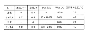
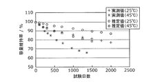
- FIG. 13A is a diagram showing test conditions under which the state of the storage element at a predetermined time of the storage element state estimation device according to Embodiment 1 of the present invention and Comparative Example 2 are estimated.
- FIG. 12A is a view showing a result of estimation of the state of the storage element at a predetermined time after a long period of time in the storage element state estimation device according to Embodiment 1 of the present invention and Comparative Example 1.
- FIG. 12B is a diagram showing an estimation result of the state of the storage element at a predetermined time after
- FIG. 13B is a diagram showing test conditions under which the state of the storage element at a predetermined time of the storage element state estimation device according to Embodiment 1 of the present invention and Comparative Example 2 are estimated.
- FIG. 13C is a diagram showing test conditions under which the state of the storage element at a predetermined time of the storage element state estimation device according to Embodiment 1 of the present invention and Comparative Example 2 are estimated.
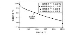
- FIG. 14A is a diagram showing an estimation result of the state of the storage element at a predetermined time of the storage element state estimation device according to Embodiment 1 of the present invention.
- FIG. 14B is a diagram showing an estimation result of the state of the storage element at a predetermined time of the device described in Patent Document 2 as Comparative Example 2.
- FIG. 14C is a diagram showing an estimation result of the state of the storage element at a predetermined time of the storage element state estimation device according to Embodiment 1 of the present invention and Comparative Example 2.
- FIG. 15A is a diagram for explaining the charge and discharge history acquired by the history acquisition unit according to the first modification of the first embodiment of the present invention.
- FIG. 15B is a diagram for explaining the charge and discharge history acquired by the history acquisition unit according to the first modification of the first embodiment of the present invention.
- FIG. 15C is a diagram for explaining the charge and discharge history acquired by the history acquisition unit according to the first modification of the first embodiment of the present invention.
- FIG. 16 is a diagram for explaining the charge and discharge history acquired by the history acquisition unit according to the first modification of the first embodiment of the present invention.
- FIG. 17A is a diagram showing a change in capacity retention rate when the history acquisition unit according to the first modification of the first embodiment of the present invention updates the charge and discharge history in a plurality of predetermined periods.
- FIG. 17B is a diagram showing a change in capacity retention rate when the history acquisition unit according to the first modification of the first embodiment of the present invention updates the charge and discharge history in a plurality of predetermined periods.
- FIG. 18A is a diagram for explaining a process in which the deterioration value estimation unit according to the second modification of the first embodiment of the present invention corrects aging information and energization deterioration information.
- FIG. 18A is a diagram for explaining a process in which the deterioration value estimation unit according to the second modification of the first embodiment of the present invention corrects aging information and energization deterioration information.
- FIG. 18B is a diagram for explaining a process in which the deterioration value estimation unit according to the second modification of the first embodiment of the present invention corrects aging information and energization deterioration information.
- FIG. 19A is a diagram showing a state before the deterioration value estimation unit according to the second modification of the first embodiment of the present invention corrects the aged deterioration information and the energization deterioration information.
- FIG. 19B is a diagram showing a state before the deterioration value estimation unit according to the second modification of the first embodiment of the present invention corrects aging deterioration information and energization deterioration information.
- FIG. 19A is a diagram showing a state before the deterioration value estimation unit according to the second modification of the first embodiment of the present invention corrects the aged deterioration information and the energization deterioration information.
- FIG. 19B is a diagram showing a state before the deterioration value estimation unit according to the second modification
- FIG. 19C is a diagram showing a state before the deterioration value estimation unit according to the second modification of the first embodiment of the present invention corrects the aged deterioration information and the energization deterioration information.
- FIG. 20A is a diagram showing a state after the deterioration value estimation unit according to the second modification of the first embodiment of the present invention corrects the aged deterioration information and the energization deterioration information.
- FIG. 20B is a diagram showing a state after the deterioration value estimation unit according to the second modification of the first embodiment of the present invention corrects the aged deterioration information and the energization deterioration information.
- FIG. 20A is a diagram showing a state after the deterioration value estimation unit according to the second modification of the first embodiment of the present invention corrects the aged deterioration information and the energization deterioration information.
- FIG. 20B is a diagram showing a state after the deterioration value estimation unit according
- FIG. 20C is a diagram showing a state after the deterioration value estimation unit according to the second modification of the first embodiment of the present invention corrects the aged deterioration information and the energization deterioration information.
- FIG. 21 is a block diagram showing a functional configuration of a storage system provided with a storage element state estimation device according to Embodiment 2 of the present invention.
- FIG. 22 is a block diagram showing a functional configuration of a power storage system provided with a power storage element state estimation device according to the first modification of the second embodiment of the present invention.
- FIG. 23 is a block diagram showing a functional configuration of a power storage system provided with a power storage element state estimation device according to the second modification of the second embodiment of the present invention.
- FIG. 24 is a block diagram showing a configuration for realizing a storage element state estimation device according to the embodiment of the present invention and the modification thereof with an integrated circuit.
- the degradation state inside the storage element will be different, but in the above-mentioned conventional technology, the degradation state inside the storage element is not taken into account, the degradation inside the storage element The estimation accuracy is low because the continuity of the state is not secured.
- the present invention has been made to solve the above-described problems, and an object of the present invention is to provide a storage element state estimation device and a storage element state estimation method that can improve the estimation accuracy of the storage element state.
- a storage element state estimation device is a storage element state estimation device that estimates a state of a storage element at a predetermined time, the storage element up to the predetermined time Information indicating the deterioration degree of time-dependent deterioration in which the storage element is deteriorated with time in an open-circuit state, and a history acquisition unit for acquiring a charge / discharge history of the Information indicating the degree of deterioration of working electricity dependent deterioration, which is deterioration due to current flow excluding time-related deterioration, is used as information about working electricity dependent judgment, and the above electricity storage A value indicating the amount of deterioration with time of the element is taken as the value of deterioration over time, and a value showing the amount of deterioration of the electricity storage of the storage element is taken as the electricity deterioration value.
- a deterioration value estimation unit for estimating the time-lapse deterioration value at the predetermined time and the energization deterioration value using the time-lapse deterioration information and the energization deterioration information according to the charge and discharge history, and the time degradation value and And a state estimation unit configured to estimate a state of the storage element at the predetermined time using the current degradation value.
- the storage element state estimation device estimates the aging deterioration value and the energization deterioration value of the storage element at a predetermined time using the aging information and the energization deterioration information according to the charge and discharge history.
- the state of the storage element at the predetermined time is estimated.
- the deterioration of the storage element is divided into time-lapse deterioration that degrades with the passage of time even in a non-energized state, and energization deterioration that is degraded by energization even if the time-lapse deterioration does not occur.
- the condition of use of the storage element is different such as the amount of energization and the use temperature during the period of non-energization and closed-circuit state
- the deterioration state of the aging and the energization deterioration inside the storage element will be different. It is necessary to separately consider aging deterioration and energization deterioration. For this reason, according to the storage element state estimation device, the estimation accuracy of the state of the storage element can be improved by dividing the deterioration inside the storage element into time-dependent deterioration and energization deterioration to estimate the deterioration value.
- the information processing apparatus further includes a deterioration information acquisition unit that acquires the temporal deterioration information and the energization deterioration information, and the history acquisition unit is a history by period that is a charge / discharge history corresponding to each of a plurality of periods up to the predetermined time.
- the charge / discharge history including (history by predetermined term / period) is acquired, the deterioration information acquisition unit acquires the temporal deterioration information and the energization deterioration information according to each of the period-based histories, and the deterioration value
- the estimation unit calculates the aging deterioration value and the energization deterioration value for each history by period using the aging deterioration information and the energization deterioration information according to the history by period, and calculates the aging deterioration value calculated
- the current deterioration value may be integrated in the order of progress of the history by period, and the time deterioration value and the current deterioration value at the predetermined time may be calculated.
- the storage element state estimation device acquires time-lapse deterioration information and energization deterioration information according to each of the history by period. That is, since the deterioration state inside the storage element changes with the passage of time, the state of the storage element is estimated by estimating the deterioration value using the time-lapse deterioration information and the energization deterioration information corresponding to each of the history by period. The estimation accuracy of can be improved.
- the storage element state estimation device calculates an aging deterioration value and an energization deterioration value for each period history by using the aging information and the energization deterioration information corresponding to each of the period history, and calculates the chronological order of the history by period.
- the integration is performed to calculate the time-lapse deterioration value and the energization deterioration value at a predetermined time.
- the continuity of the degradation state inside the storage element can be secured by integrating the time-lapse degradation value and the energization degradation value in the order of time. For this reason, since the time-lapse deterioration value and the energization deterioration value at a predetermined time can be accurately calculated, the estimation accuracy of the state of the storage element can be improved.
- the history acquisition unit is a history by period which is a history by period from a first time point to a second time point, and a history by time period which is a history by period from the second time point to a third time point
- the charge / discharge history including the first information is obtained, and the deterioration information acquisition unit receives first time deterioration information, which is time deterioration information according to the first period history, and time deterioration information according to the second period history.
- the second time-lapse information which is the second time-lapse information
- the deterioration value estimation unit using the first time-lapse information
- the first time-lapse value as the time-lapse value from the first time point to the second time point
- Second state deterioration value from the second time point to the third time point using the second time-lapse deterioration information, with the state where the first time-lapse deterioration value is deteriorated as a start time point.
- the aging deterioration value is calculated, and the first aging deterioration value and the second aging deterioration value are added. Te, it may be possible to calculate the time degradation value from the first time point to the third point.
- the storage element state estimation device calculates the first time-lapse deterioration value from the first time point to the second time point, and the state in which the first time-lapse deterioration value is deteriorated is the second time point.
- the second deterioration value over time from the second time point to the third time point is calculated, and the first time deterioration value and the second time deterioration value are added to calculate the time deterioration value from the first time point to the third time point.
- the history acquisition unit is configured to apply a current to the storage element after the fifth time point, and a history for a third period, which is a history by period from the fourth time point to the fifth time point when the power storage element is energized.
- the charge / discharge history including the history by period which is the history by period from the sixth time point to the seventh time point obtained is acquired, and the deterioration information acquisition unit is energized according to the history by third period
- the first energization deterioration information, which is degradation information, and the second energization deterioration information, which is energization deterioration information according to the fourth period history, are acquired, and the degradation value estimation unit uses the first energization deterioration information.
- the first current deterioration value which is the current deterioration value from the fourth time point to the fifth time point, is calculated, and the second current deterioration is determined with the state in which the first current deterioration value is deteriorated as a start time point It is the energization degradation value from the sixth time point to the seventh time point using information
- Two current calculating the degradation value by adding the said second current degradation value and the first current degradation value, may be possible to calculate the current degradation value from the fourth time point to the seventh time point.
- the storage element state estimation device calculates the first energization deterioration value from the fourth time point to the fifth time point when the storage element is energized, and the state in which the first energization deterioration value is degraded
- the history acquisition unit may calculate an average SOC which is an average value of SOC of the storage element at a plurality of time points, an SOC variation amount which is a fluctuation amount at the plurality of time points, and a plurality of temperatures of the storage element.
- the charge / discharge history including an average temperature, which is an average value, is acquired, and the deterioration value estimation unit uses the average SOC, the SOC variation amount, and the average temperature included in the charge / discharge history to perform the aging over time.
- the deterioration value and the energization deterioration value may be estimated.
- the storage element state estimation device acquires the average SOC of the storage element, the SOC variation amount, and the average temperature, and uses the average SOC, the SOC variation amount, and the average temperature to determine the time degradation value and the energization degradation. Estimate the value.
- data of the storage element is continuously measured over a long period of time in order to estimate the time-lapse deterioration value and the energization deterioration value, a large amount of data is generated except when the data can be constantly transferred online. Data needs to be stored in memory.
- the inventors of the present application maintain the estimation accuracy of the time-lapse deterioration value and the energization deterioration value while compressing the data amount by using the average SOC and the SOC fluctuation amount of the storage element and the average temperature. I found that I could do it. Therefore, the storage element state estimation device compresses (reduces) the amount of data by using the average value of the SOC and temperature without using a huge amount of SOC and temperature data, and deterioration over time It is possible to accurately estimate the value and the energization degradation value.
- the history acquisition unit may update the acquired charge and discharge history to a charge and discharge history for each predetermined period.
- the storage element state estimation device updates the acquired charge and discharge history to the charge and discharge history for each predetermined period.
- the inventors of the present invention for example, even if the charge / discharge history acquired every one second is updated to the charge / discharge history every predetermined period such as 10 minutes, the estimation accuracy of the time-lapse deterioration value and the energization deterioration value is equal. It has been found that it can be maintained. Therefore, the storage element state estimation device can compress (reduce) the amount of data and accurately estimate the time-lapse deterioration value and the energization deterioration value.
- the deterioration value estimation unit corrects the aging deterioration information and the energization deterioration information using the charge and discharge history, and uses the aging deterioration information and the energization deterioration information after correction to correct the aging deterioration value and the aging deterioration value. It is also possible to estimate the energization deterioration value.
- the storage element state estimation device corrects the aging deterioration information and the energization deterioration information using the charge and discharge history, and estimates the aging deterioration value and the energization deterioration value.
- the storage element state estimation device estimates the aging deterioration value and the energization deterioration value.
- the storage element state estimation device corrects the aging deterioration information and the energization deterioration information using the charge and discharge history, and estimates the aging deterioration value and the energization deterioration value.
- the storage element state estimation device corrects the aging deterioration information and the energization deterioration information according to the charge and discharge history in the past, thereby obtaining the aging degradation value without acquiring new time degradation information and the energization deterioration information.
- the energization deterioration value can be estimated with high accuracy.
- the predetermined time is a future time
- the history acquisition unit acquires a past charge and discharge history, and estimates the charge and discharge history up to the future time.
- a charge / discharge history is acquired, and the deterioration value estimation unit uses the time-lapse deterioration information and the energization deterioration information according to the charge / discharge history up to the future time, and the time-lapse deterioration value at the future time And the conduction deterioration value, and the state estimation unit estimates the state of the storage element at the future time using the time-lapse deterioration value at the future time and the conduction deterioration value. It may be good.
- the storage element state estimation device obtains the past charge and discharge history, and estimates the charge and discharge history up to the future time point, thereby estimating the state of the power storage element at the future time point.
- the storage element state estimation device can accurately estimate the state of the storage element at a future time.
- the history acquisition unit may receive the charge / discharge history from the power storage device having the power storage element, and the state estimation unit may transmit the estimated state of the power storage element to the power storage device.
- the storage element state estimation device receives the charge / discharge history from the storage device having the storage element, and transmits the estimated state of the storage element to the storage device. That is, in the case where a control board or the like included in the storage device is to estimate the state of the storage element, the control board needs to perform an enormous amount of calculations, but by providing a storage element state estimation device separately from the control board. The amount of calculations performed by the control board can be reduced.
- Embodiment 1 First, the configuration of power storage system 10 will be described.
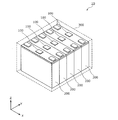
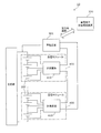
- FIG. 1 is an external view of a storage system 10 including a storage element state estimation device 100 according to Embodiment 1 of the present invention.
- the storage system 10 includes a plurality (five in the figure) storage element state estimation devices 100, a plurality (five in the figure) storage elements 200, and the plurality of storage element states estimated.
- a storage case 300 for storing the device 100 and the plurality of storage elements 200 is provided. That is, one storage element state estimation device 100 is arranged corresponding to one storage element 200.
- the storage element state estimation device 100 is a flat circuit board which is disposed above the storage element 200 and has a circuit for estimating the state of the storage element 200 at a predetermined time. Specifically, one storage element state estimation device 100 is connected to one storage element 200, acquires information from the one storage element 200, and obtains the one storage element 200 at a predetermined time. Estimate the state such as the deterioration state.
- the storage element state estimation device 100 is disposed above each storage element 200, the storage element state estimation device 100 may be disposed anywhere. Further, the shape of the storage element state estimation device 100 is not particularly limited.
- the number of storage element state estimation devices 100 is not limited to five, and may be another plural number or one. That is, one storage element state estimation device 100 may be arranged corresponding to a plurality of storage elements 200, and a plurality of storage element state estimation devices 100 are arranged corresponding to one storage element 200. It may be That is, a configuration in which the number of storage element state estimation devices 100 are connected to the number of storage elements 200 may be used. The detailed functional configuration of the storage element state estimation device 100 will be described later.
- the storage element 200 is a secondary battery capable of charging and discharging electricity, and more specifically, a non-aqueous electrolyte secondary battery such as a lithium ion secondary battery. Further, in the figure, five rectangular storage elements 200 are arranged in series to constitute a battery pack. The number of storage elements 200 is not limited to five, and may be another plural number or one. Further, the shape of the storage element 200 is not particularly limited, and may be a cylindrical shape, an elongated cylindrical shape, or the like.
- the storage element 200 includes a container, and electrode terminals (a positive electrode terminal and a negative electrode terminal) protruding from the container, and the electrode body, the electrode body, and the electrode terminal are connected to the inside of the container.
- Current collectors positive electrode current collector and negative electrode current collector
- the electrode body is formed by winding a positive electrode, a negative electrode and a separator.
- the electrode assembly may not be a wound electrode assembly, but may be a laminated electrode assembly in which flat plate electrodes are laminated.
- the positive electrode is an electrode plate in which a positive electrode active material layer is formed on the surface of a positive electrode base material layer which is a long strip-like metal foil made of aluminum, an aluminum alloy or the like.
- a positive electrode active material used for a positive electrode active material layer if it is a positive electrode active material which can occlude-discharge lithium ion, a well-known material can be used suitably.
- polyanionic compounds such as LiMPO 4 , LiMSiO 4 , LiMBO 3 (M is one or more transition metal elements selected from Fe, Ni, Mn, Co, etc.) as a positive electrode active material, lithium titanate, Spinel type lithium manganese oxide such as LiMn 2 O 4 or LiMn 1.5 Ni 0.5 O 4 , LiMO 2 (M is a transition metal selected from Fe, Ni, Mn, Co, etc.) Lithium transition metal oxides such as elements) can be used.
- the negative electrode is an electrode plate in which a negative electrode active material layer is formed on the surface of a negative electrode base material layer which is a long strip-like metal foil made of copper, copper alloy or the like.
- a negative electrode active material used for a negative electrode active material layer if it is a negative electrode active material which can occlude-discharge lithium ion, a well-known material can be used suitably.
- lithium metal lithium-silicon containing alloy such as lithium-silicon, lithium-aluminum, lithium-lead, lithium-tin, lithium-aluminum-tin, lithium-gallium, and wood alloy
- lithium-silicon containing alloy such as lithium-silicon, lithium-aluminum, lithium-lead, lithium-tin, lithium-aluminum-tin, lithium-gallium, and wood alloy
- Other alloys capable of absorbing and desorbing lithium carbon materials (eg, graphite, non-graphitizable carbon, graphitizable carbon, low-temperature calcined carbon, amorphous carbon, etc.), silicon oxides, metal oxides, lithium metal oxides (Li 4 Ti 5 O 12 etc.), polyphosphate compounds, or compounds of transition metals and Group 14 to 16 elements such as Co 3 O 4 or Fe 2 P, which are generally called conversion negative electrodes, etc.
- Be lithium metal, lithium alloy (lithium-silicon containing alloy such as lithium-silicon, lithium-a
- the separator is a microporous sheet made of a resin.
- the separator used for the storage element 200 is not particularly different from that used conventionally, and any known material can be used as long as it does not impair the performance of the storage element 200.
- the electrolytic solution (non-aqueous electrolyte) sealed in the container various types can be selected without particular limitation as long as it does not impair the performance of the storage element 200.
- the storage element 200 is not limited to the non-aqueous electrolyte secondary battery, and may be a secondary battery other than the non-aqueous electrolyte secondary battery, or may be a capacitor.
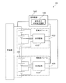
- FIG. 2 is a block diagram showing a functional configuration of the storage element state estimation device 100 according to Embodiment 1 of the present invention.
- the storage element state estimation device 100 is a device that estimates the state of the storage element 200 at a predetermined time.
- the state of the storage element 200 refers to the electrical or mechanical state of the storage element 200, and includes, for example, a degradation state indicating the degree of degradation of the storage element 200 or the like.
- the storage element state estimation device 100 includes a history acquisition unit 110, a deterioration information acquisition unit 120, a deterioration value estimation unit 130, a state estimation unit 140, and a storage unit 150.
- Storage unit 150 is a memory for storing various data for estimating the state of storage element 200 at a predetermined time, and stores charge / discharge history data 151 and deterioration information data 152.
- the history acquisition unit 110 acquires the charge / discharge history of the storage element 200 up to a predetermined point in time. Specifically, the history acquisition unit 110 is connected to the storage element 200, and detects and acquires the charge and discharge history from the storage element 200. That is, the history acquisition unit 110 is electrically connected to the electrode terminal of the storage element 200 on which the storage element state estimation device 100 is mounted by a wire such as a lead wire. Then, the history acquisition unit 110 acquires the charge / discharge history from the storage element 200 via the wiring during the period up to the predetermined time point.
- history acquisition unit 110 constantly monitors the operating state of storage element 200, and acquires the charge / discharge history whenever a predetermined change is observed in the operating state of storage element 200. For example, the history acquisition unit 110 monitors the change in voltage of the storage element 200, and when the voltage difference exceeds 0.1% of the current voltage, it is regarded that the storage element 200 has been charged and discharged. Get the discharge history. In this case, for example, the history acquisition unit 110 acquires the charge and discharge history whenever the change in voltage of the storage element 200 exceeds 0.1%. That is, the history acquisition unit 110 acquires the charge and discharge history with a sampling cycle in which the change in voltage of the storage element 200 is 0.1%.
- the timing of acquisition of the charge and discharge history is not limited to the above, and the history acquisition unit 110 acquires any charge and discharge history such as acquiring the charge and discharge history in a sampling cycle where the usage period of the storage element 200 is 1 second. You may use
- the charge / discharge history is an operation history of the storage element 200, and is information indicating a period (use period) in which the storage element 200 has been charged or discharged, and relates to charge or discharge performed by the storage element 200 during the use period. It is information including information etc.
- information indicating the use period of the storage element 200 is a date (date) and time indicating that the storage element 200 has been charged or discharged, or the storage element 200 is used. It is information including the accumulated use period and the like.
- the cumulative use period is a cumulative value of the use period of the storage element 200, and specifically, indicates a period from the use start point of the storage element 200 to a predetermined point.
- the unit of accumulated use period may be any unit representing a period such as time (hour, minute, second), day, month, or cycle (number of charge and discharge).
- the information on charging or discharging performed by the storage element 200 is information indicating the voltage, current, operating temperature, battery state, etc. at the time of charging or discharging performed by the storage element 200, and the storage element Acquired when it is considered that 200 has been charged or discharged.
- the operating temperature is the operating temperature of the storage element 200
- the history acquisition unit 110 measures the temperature of the storage element 200 by providing a thermometer for the container or the electrode terminal of the storage element 200 as the operating temperature.
- the temperature around the storage element 200 may be measured by a thermometer.
- the history acquisition unit 110 may acquire the temperature (external temperature) of the area where the storage element 200 is used as the use temperature.
- the battery state is information indicating what kind of operation state the storage element 200 is in, such as a charged state, a discharged state, a left state (state in which neither charging nor discharging). Note that when the battery state is estimated from the information indicating the voltage or current of the storage element 200, the information indicating the battery state is unnecessary.
- the history acquisition unit 110 writes the acquired charge and discharge history in the charge and discharge history data 151 stored in the storage unit 150.
- FIG. 3A is a view showing an example of the charge and discharge history written in the charge and discharge history data 151 according to the first embodiment of the present invention.
- the charge and discharge history data 151 data indicating the charge and discharge history, which is the operation history of the storage element 200 up to a predetermined time, is written as the charge and discharge history. That is, in the charge and discharge history data 151, data in which "date”, “time”, “use period”, “voltage”, “current”, “SOC”, “temperature”, and “battery state” are associated with each other. A table is written.
- the date (date) and time which are information indicating the time point when the storage element 200 has been charged or discharged, are stored in the "date” and "time”, and the storage element is stored in the "use period”.
- a value is stored that indicates the cumulative usage period for which 200 has been used. That is, the history acquisition unit 110 measures time from a timer or the like, acquires the date (year-month-day), time, and cumulative use period, and writes the date, date, and use period. Note that the history acquisition unit 110 may calculate the cumulative use period using the information stored in the “date” and the “time”, and write the calculated use period in the “use period”.
- “voltage”, “current”, “temperature”, and “battery state” indicate the voltage, current, and use during charging or discharging performed by the storage element 200 as information on charging or discharging performed by the storage element 200.
- Information indicating temperature and battery status is stored. That is, the history acquisition unit 110 acquires the voltage, current, operating temperature, and battery state of the storage element 200, and writes the “voltage”, “current”, “temperature”, and “battery state”.
- SOC stores information indicating an SOC (State Of Charge) of the storage element 200 at the time of charging or discharging performed by the storage element 200.
- SOC is calculated by the history acquisition unit 110 and written to “SOC”.
- the history acquisition unit 110 estimates the SOC from the voltage value of the storage element 200 using, for example, an SOC-OCV characteristic that indicates a relationship between the SOC and an open circuit voltage (OCV). Calculate In addition, the history acquisition unit 110 may calculate the SOC from the current value of the storage element 200 using a current integration method of integrating the charge and discharge current to estimate the SOC.
- history acquisition unit 110 generates pattern data using the relationship between the SOC of storage element 200 and the use temperature and use period, and generates the generated pattern data as charge / discharge history data of storage element 200 in charge / discharge history data 151. Write.
- FIG. 3B is a diagram showing an example of pattern data generated by the history acquisition unit 110 according to Embodiment 1 of the present invention.
- the pattern data is data indicating an operation pattern of the storage element 200.
- the pattern data is a collection of data indicating the relationship between the SOC of the storage element 200, the operating temperature, and the operating period.
- the pattern data is represented by a graph or the like showing the relationship between the SOC of the storage element 200 and the usage period, as shown in the figure.
- the pattern data is data obtained by patterning data representing a repetitive change among data representing a change in a state amount (SOC in the figure) of the storage element 200 in a period up to a predetermined time point. is there. That is, when a change as shown in the graph of FIG. 6 is repeated in the period up to the predetermined time, data indicating the change such as the graph is generated as pattern data.
- pattern data For example, if charge and discharge are repeated every weekday with changes like the graph, the data shown in the graph is generated as pattern data for the weekday. Similarly, pattern data is generated also for holidays. Note that the generation of pattern data does not have to be repeated with exactly the same charge and discharge (in the form of the same graph), and a certain deviation is allowed. The amount of deviation is appropriately determined by the setting of the user.
- the history acquisition unit 110 generates a plurality of pattern data in the period up to the predetermined time point.
- the history acquisition unit 110 may generate only one pattern data.
- the history acquisition unit 110 writes the generated pattern data into the charge / discharge history data 151 stored in the storage unit 150.
- the history acquisition unit 110 may write the pattern data to the charge / discharge history data 151 in the form of a graph as shown in the figure, or the collection of data (data table) for generating the graph.
- the charge / discharge history data 151 may be written in a form.
- the history acquisition unit 110 may delete the charge and discharge history used to generate pattern data from the charge and discharge history data 151. That is, since the charge / discharge history is patterned by the pattern data, it is not necessary to keep storing in the charge / discharge history data 151, and can be deleted from the charge / discharge history data 151.
- the history acquisition unit 110 records charge / discharge history of pattern data obtained by patterning data indicating repeated changes among data indicating changes in the state quantity of the storage element 200 up to a predetermined time point. Get as. In other words, history acquisition unit 110 uses the charge and discharge history stored in charge and discharge history data 151 to indicate data indicating a repetitive change among data indicating a change in the amount of state of storage element 200 up to a predetermined point in time. Generate and acquire pattern data obtained by patterning the
- the state quantity of the storage element 200 is a numerical value indicating the state of the storage element 200, and for example, the voltage or current of the storage element 200, or the charge / discharge quantity or SOC indicating the charge / discharge state of the storage element 200. It is. In the present embodiment, the state quantity of the storage element 200 is the SOC of the storage element 200.
- the storage element state estimation device 100 uses the pattern data acquired as the charge and discharge history by the history acquisition unit 110 to estimate the state of the storage element 200 at a predetermined time. Note that the storage element state estimation device 100 does not use pattern data, but uses the charge / discharge history as shown in FIG. 3A acquired by the history acquisition unit 110 to determine the state of the storage element 200 at a predetermined time. It does not matter to estimate.
- the deterioration information acquisition unit 120 acquires time-lapse deterioration information and energization deterioration information according to the charge and discharge history acquired by the history acquisition unit 110. Specifically, the deterioration information acquisition unit 120 refers to the deterioration information data 152 stored in the storage unit 150, and according to the charge / discharge history among the deterioration information written in advance in the deterioration information data 152. The time-lapse deterioration information and the energization deterioration information are extracted and acquired.
- the aged deterioration information is information indicating the degree of degradation of the aged deterioration in which the storage element 200 is aged and deteriorated in the non-energized state
- the energized deterioration information is the deterioration due to energization excluding the aged deterioration. It is the information which shows the degradation degree of energization degradation which is.
- the temporal deterioration information is a coefficient of a mathematical expression indicating the amount of temporal deterioration of the storage element 200
- the conductive deterioration information is a coefficient of a mathematical expression indicating the amount of conduction degradation of the storage element 200.
- the temporal deterioration information is a coefficient indicating the degree of deterioration in a period in which the storage element 200 is not charged / discharged, such as at night.
- the energization deterioration information is a value obtained by subtracting the deterioration coefficient over time in the charging / discharging period from the coefficient indicating the deterioration degree in the charging / discharging period of the storage element 200. That is, the sum of the time-lapse deterioration information and the energization deterioration information becomes a coefficient indicating the degree of deterioration in a period in which the storage element 200 is charged and discharged.
- non-energized state refers to a state in which the storage element 200 is not energized, that is, a state in which the value of the current flowing through the storage element 200 is zero.
- a small current may always flow through the storage element 200.
- the current value is zero, but also the current value is less than or equal to a certain value or the SOC change amount is less than a certain value. Also in the case where it becomes, it considers that it is a "non-energized state.”
- the deterioration information acquisition unit 120 determines the SOC and use of the storage element 200 in the charge and discharge history.
- the aging information and the energization deterioration information according to at least one of the temperatures are acquired.
- degradation information acquisition unit 120 determines the SOC and use temperature of storage device 200 in the charge and discharge history.
- the time-lapse deterioration information and the energization deterioration information according to are acquired.
- the history acquisition unit 110 acquires the charge / discharge history including the history by period which is the charge / discharge history corresponding to each of the plurality of periods up to the predetermined time
- the deterioration information acquisition unit 120 respectively The time-lapse deterioration information and the energization deterioration information according to are acquired.
- the deterioration information (that is, the time-lapse deterioration information and the energization deterioration information acquired by the deterioration information acquisition unit 120) written in advance in the deterioration information data 152 will be described below.
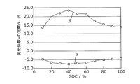
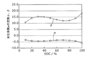
- FIG. 4A and FIG. 4B are diagrams showing an example of the deterioration information written in advance in the deterioration information data 152 according to Embodiment 1 of the present invention.
- the degradation model formula of the storage element 200 can be modeled as f (t) because at least the use period t is taken as a variable.
- the degradation rate k (t) of the storage element 200 can be obtained by differentiating the degradation model equation f (t) of the storage element 200 with respect to the variable t.
- the degradation rate k (t) 3 bt 2 +2 ct + d.
- the proportional constant and the constant term (a, b, c or d) in the calculated deterioration rate are deterioration information, which will be hereinafter referred to as a deterioration coefficient.
- the graph showing the change of the deterioration coefficient when the SOC of the storage element 200 and the operating temperature are changed is a map related to the use condition dependency of the deterioration coefficient (the deterioration coefficient a in the figure) as shown in FIG. 4B. It can also be expressed as Based on these, a model equation for calculating the deterioration rate can be constructed.
- the aging deterioration coefficient as aging deterioration information and the energization deterioration coefficient as energization deterioration information are obtained in advance, and are written in the degradation information data 152 in advance.
- electrical_connection deterioration coefficient can be acquired by the following capacity
- 1 CA constant current constant voltage charging is performed up to a charge termination condition 0.02 CA, charge upper limit voltage 4.15 V, and discharging is performed constant current discharge up to a discharge lower limit voltage 2.75 V.
- the temperature is 25 ° C. for both charging and discharging.
- 1 CA constant current charging is performed up to a charge termination condition 0.02 CA, charge upper limit voltage 4.15 V, and discharging is performed constant current discharge up to a discharge lower limit voltage 2.75 V.
- cycle test it is used for the data for calculating the electrification deterioration coefficient in various SOC range by repeating charge / discharge from SOC 90% to SOC 70%, repeat charge / discharge from SOC 30% to SOC 10%, etc. Is preferred.
- temperature is implemented at -10 ° C., 0 ° C., 10 ° C., 25 ° C., 45 ° C., and 55 ° C. for both charging and discharging.
- SOC is carried out in 10% steps of 10 to 100%, and the temperature is carried out at ⁇ 10 ° C., 0 ° C., 10 ° C., 25 ° C., 45 ° C., and 55 ° C.
- the data for calculating the deterioration coefficient over time can be acquired by the leaving test and the capacity confirmation test, and the data for calculating the energization deterioration coefficient can be acquired by the cycle test and the capacity confirmation test.
- the conduction deterioration which is the deterioration coefficient obtained by subtracting the influence of the deterioration over time at the time of constant current energization by subtracting the average value of the deterioration over time for each SOC from the deterioration coefficient obtained from the cycle test. Coefficients can be calculated.
- the charge condition of the cycle test is constant current charge, but when the charge condition of the cycle test is constant current constant voltage charge, the conduction deterioration coefficient is calculated by the following method.
- a period during which the charging current in the constant voltage charging period is attenuated is assumed to be a standing test period, and is regarded as a combined durability test of a cycle test and a standing test. Then, apply the SOC deterioration rate of 100% to the storage test period after charging, apply the SOC deterioration rate of 0% to the storage test period of the discharge end, and degrade during energization other than the storage test period. Set the coefficient as unknown x. Next, assuming the above conditions as charge and discharge patterns, the pattern is applied to the test results to optimize the deterioration coefficient x at the time of energization, thereby calculating an apparent deterioration coefficient only at the time of constant current energization.
- the conduction deterioration coefficient which is a deterioration coefficient obtained by subtracting the influence of the time-lapse deterioration at the time of constant current current It can be calculated.
- the aging deterioration coefficient and the energization deterioration coefficient may be written in the deterioration information data 152 in the form of a graph as shown in FIG. 4A or 4B, or written in the deterioration information data 152 in the form of a data table. It is also good.
- the deterioration value estimation unit 130 determines the time-lapse deterioration value and the conduction deterioration of the storage element 200 at a predetermined point in time, which is obtained from the time-lapse deterioration information and the conduction deterioration information Estimate the current degradation value indicating the amount. That is, the deterioration value estimation unit 130 estimates the time degradation value and the energization degradation value using the time degradation information and the energization degradation information acquired by the degradation information acquisition unit 120.
- the deterioration value estimation unit 130 calculates the aging deterioration value and the energization deterioration value for each period history by using the aging information and the energization deterioration information corresponding to each of the history by period, and the calculation
- the aging deterioration value and the energization deterioration value are integrated in the order of progress of the history by period, and the aging deterioration value and the energization deterioration value at a predetermined time are calculated.
- the deterioration information acquisition unit 120 includes first time deterioration information which is time deterioration information corresponding to the first period history and second time deterioration information which is time deterioration information according to the second period history. get.
- the deterioration value estimation unit 130 uses the first time-lapse deterioration information to calculate a first time-lapse deterioration value that is a time-lapse deterioration value from the first time point to the second time point.
- the deterioration value estimation unit 130 uses the second time-lapse information as the start time point when the first time-lapse deterioration value has been deteriorated, and the second time-lapse value from the second time point to the third time point 2 Calculate the aging deterioration value.
- the deterioration value estimation unit 130 adds the first time-lapse deterioration value and the second time-lapse deterioration value to calculate the time-lapse deterioration value from the first time point to the third time point.
- the history acquisition unit 110 applies a current to the storage element 200 after the fifth time point, and a history for the third period, which is a history by period from the fourth time point to the fifth time point when the power storage element 200 is energized. It is assumed that the charge / discharge history including the fourth history by history, which is the history by period from the sixth time point to the seventh time point performed, is acquired.
- the deterioration information acquisition unit 120 includes first conduction deterioration information, which is conduction deterioration information according to the third period history, and second conduction deterioration information, which is current conduction deterioration information according to the fourth period history. get.
- the deterioration value estimation unit 130 uses the first energization deterioration information to calculate the first energization deterioration value, which is the energization deterioration value from the fourth time point to the fifth time point. Further, the deterioration value estimation unit 130 uses the second conduction deterioration information as a start time point when the first conduction deterioration value has been deteriorated, and the second deterioration value is a current conduction deterioration value from the sixth time point to the seventh time point. (2) Calculate the current degradation value. Then, the deterioration value estimation unit 130 adds the first conduction deterioration value and the second conduction deterioration value to calculate the conduction deterioration value from the fourth time point to the seventh time point.
- the aging deterioration value is the amount of degradation (the amount of aging deterioration) in the aging of the storage element 200
- the value of the energization deterioration is the amount of degradation in the energization deterioration of the storage element 200 (amount of energization degradation). is there.
- State estimating unit 140 estimates the state of power storage element 200 at a predetermined time, using the time-lapse deterioration value and the energization deterioration value estimated by deterioration value estimating unit 130. Specifically, state estimating unit 140 estimates the deterioration state of storage element 200 at the predetermined time point by adding the time-lapse deterioration value at the predetermined time point and the energization deterioration value.
- prescribed time is the concept including not only the present or the past time but the future time.
- history acquisition unit 110 takes a predetermined time as a future time, acquires the past charge and discharge history, and performs charge and discharge up to the future time. By estimating the history, the predicted value of the charge / discharge history of the storage element 200 up to the future time is acquired as the charge / discharge history. Note that the history acquisition unit 110 may acquire the predicted value of the charge / discharge history up to a future time point from the user's input or the like instead of calculating it from the actual value of the past charge / discharge history. .
- the deterioration information acquisition unit 120 acquires time-lapse deterioration information and energization deterioration information up to the future point in time according to the charge and discharge history.
- the deterioration value estimation unit 130 estimates the time-lapse deterioration value and the conduction deterioration value at the future time point, using the time-lapse deterioration information and the conduction deterioration information up to the future time point.
- state estimating unit 140 estimates the state of power storage element 200 at the future time point, using the time-lapse deterioration value and the energization deterioration value at the future time point.
- state estimation unit 140 can estimate, for example, the remaining life of storage element 200.
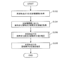
- FIG. 5 is a flowchart showing an example of a process in which the storage element state estimation device 100 according to Embodiment 1 of the present invention estimates the state of the storage element 200 at a predetermined time.
- history acquisition part 110 acquires the charging / discharging log
- the history acquisition unit 110 records charge / discharge history of pattern data obtained by patterning data indicating repeated changes among data indicating changes in the state quantity of the storage element 200 up to a predetermined time point. Get as.
- FIG. 6 is a diagram showing an example of pattern data acquired by the history acquisition unit 110 according to the first embodiment of the present invention.
- Points A to F in FIG. 6 indicate changing points of the state quantity (SOC in FIG. 6) in the pattern data.
- the deterioration information acquisition unit 120 acquires time-lapse deterioration information and energization deterioration information according to the charge / discharge history acquired by the history acquisition unit 110 (S104: deterioration information acquisition step).
- the temporal deterioration information and the energization deterioration information acquired by the deterioration information acquisition unit 120 will be described in detail below.
- FIG. 7A is a diagram for explaining aging deterioration information according to the interval AB in FIG. 6 acquired by the deterioration information acquiring unit 120 according to the first embodiment of the present invention
- FIG. 7B is a diagram illustrating the first embodiment of the present invention It is a figure explaining the electricity supply degradation information according to AB between FIG. 6 which the degradation information acquisition part 120 which concerns on B acquires.
- FIG. 7A shows the transition of deterioration over time
- FIG. 7B shows the transition of deterioration due to energization. That is, FIG. 7A shows deterioration over time and FIG. 7B shows deterioration of current when the deterioration of the storage element 200 when charge and discharge of SOC 45% to 100% are repeatedly performed is divided into time deterioration and current deterioration. It shows.
- the deterioration information acquisition unit 120 acquires the deterioration coefficient over time as the deterioration information over time corresponding to the graph in FIG. 7A between AB in the pattern data shown in FIG. Since the temporal deterioration coefficient also changes according to the change in SOC between the ABs, the deterioration information acquisition unit 120 acquires the average value of the temporal deterioration coefficients (at SOC 45% to 100%) between the ABs using a weighted average or the like. Do. Note that the deterioration information acquisition unit 120 may acquire the time-lapse deterioration coefficient in the average value (SOC 72.5%) of the SOC between the AB.
- the deterioration information acquisition unit 120 acquires a conduction deterioration coefficient corresponding to the graph in FIG. 7B as the conduction deterioration information between the points AB. That is, the deterioration information acquisition unit 120 acquires the energization deterioration coefficient when the storage element 200 is charged from 45% to 100% of SOC.
- the deterioration information acquisition unit 120 calculates the deterioration coefficient as described in FIGS. 4A and 4B for each of the time-lapse deterioration information and the energization deterioration information, and a constant for determining the deterioration coefficient (see FIG. 4A). Then, ⁇ , ⁇ ) etc. are acquired. Specifically, the deterioration information acquisition unit 120 determines, among the data written in advance in the deterioration information data 152, the equation, the constant, etc. according to the charge / discharge history (corresponding to the graph of FIG. 7A or 7B). Extract and get
- FIG. 7C is a view for explaining the time-lapse deterioration information according to the interval between BCs in FIG. 6 acquired by the deterioration information acquisition unit 120 according to the first embodiment of the present invention. Specifically, the figure shows deterioration over time when the storage element 200 is left at 100% SOC.
- the deterioration information acquisition unit 120 acquires the deterioration coefficient with time corresponding to the graph in FIG. 7C as the deterioration information over time between BC in the pattern data shown in FIG. That is, the deterioration information acquisition unit 120 acquires the deterioration coefficient over time in the value of SOC (SOC 100%) between the BCs. Since charging and discharging are not performed between the BCs, the deterioration information acquiring unit 120 acquires only the aging deterioration information and does not acquire the conduction deterioration information, or the conduction deterioration information (the conduction deterioration coefficient) Acquired as "0".
- the deterioration information acquisition unit 120 sequentially acquires the time-lapse deterioration information and the energization deterioration information according to the charge / discharge history of each section.
- the scale of the vertical axis (capacity maintenance ratio) of the graphs in FIGS. 7A to 7C is an example, and is appropriately determined according to the degree of deterioration of the storage element 200 that estimates the state. The same applies to the following FIGS.
- the deterioration value estimation unit 130 generates an aging deterioration value indicating the amount of aging deterioration of the storage element 200 at a predetermined time, obtained from the aging information and energization deterioration information acquired by the degradation information acquisition unit 120.
- An energization deterioration value indicating the amount of deterioration is estimated (S106: deterioration value estimation step).
- deterioration value estimation unit 130 uses time-lapse deterioration information and energization deterioration information according to each of the history by period (in the present embodiment, the charge / discharge history of each section in the pattern data described above), The temporal deterioration value and the energization deterioration value are calculated for each history by period. Then, the deterioration value estimation unit 130 integrates the calculated time-lapse deterioration value and the current conduction deterioration value in the order of progress of the history by period to calculate the time-lapse deterioration value and the current deterioration value at a predetermined time.
- the deterioration value estimation unit 130 estimates the time-lapse deterioration value and the energization deterioration value at a predetermined time.
- the state estimation unit 140 estimates the state of the storage element 200 at a predetermined time using the time-lapse deterioration value and the energization deterioration value estimated by the deterioration value estimation unit 130 (S108: state estimation step).
- the state estimation unit 140 estimates the deterioration state of the storage element 200 at the predetermined time point by adding the time-lapse deterioration value at the predetermined time point and the energization deterioration value.
- the storage element state estimation device 100 can estimate the state of the storage element 200 at present, in the past, or in the future. By the above, the process in which the storage element state estimation device 100 estimates the state of the storage element 200 at a predetermined time point ends.
- FIG. 8 is a flowchart showing an example of a process in which the deterioration value estimation unit 130 according to Embodiment 1 of the present invention estimates the time-lapse deterioration value and the energization deterioration value at a predetermined time.
- the deterioration value estimation unit 130 calculates the time-lapse deterioration value and the energization deterioration value of the initial period-based history (S202). That is, the deterioration value estimation unit 130 calculates the time-lapse deterioration value and the energization deterioration value of the time-period history between AB by using the time-lapse deterioration coefficient and the energization deterioration coefficient according to the initial time-based history.
- deterioration value estimating unit 130 uses the temporal deterioration coefficient and the energization deterioration coefficient according to the history by period in AB in the pattern data shown in FIG. The amount of deterioration over time and the amount of deterioration due to energization which are the amount of deterioration are calculated.
- the deterioration value estimation unit 130 repeats the following processing (S206 to S208) until all the history by period is finished (loop 1: S204 to S210).
- the deterioration value estimation unit 130 calculates the amount of deterioration over time and the amount of deterioration due to current flow of the next period-based history (S206). That is, the deterioration value estimation unit 130 calculates the amount of deterioration over time and the amount of deterioration of current passage of the next period-by-period history using the deterioration coefficient of passage of time and the current passage deterioration coefficient according to the next history by period.
- the deterioration value estimation unit 130 uses the temporal deterioration coefficient and the energization deterioration coefficient according to the history by period in BC in the pattern data shown in FIG. Calculate the amount of current degradation.
- the deterioration value estimation unit 130 adds each of the temporal deterioration amount and the energization deterioration amount (S208). That is, the deterioration value estimation unit 130 adds the temporal deterioration amount of the initial period history and the temporal deterioration amount of the next period history, and adds the current period deterioration amount of the initial period history and the next period history And the amount of current degradation of the
- the deterioration value estimation unit 130 calculates the amount of deterioration over time and the amount of deterioration of current flow for each history by period, and integrates the calculated amount of deterioration over time and the current amount of current deterioration in the order of progress of history by period. The amount of deterioration over time and the amount of current deterioration at a predetermined time are calculated.
- the process in which the deterioration value estimation unit 130 estimates the amount of deterioration over time and the amount of current deterioration at a predetermined time will be described more specifically.
- FIG. 9 is a diagram for explaining a process in which the deterioration value estimation unit 130 according to the first embodiment of the present invention estimates the amount of deterioration over time at a predetermined time.
- FIG. 10 is a diagram for explaining a process in which the deterioration value estimation unit 130 according to the first embodiment of the present invention estimates the amount of degradation due to current flow at a predetermined time.
- point A in the pattern data shown in FIG. 6 is taken as the first time point
- point B is taken as the second time point
- point C is taken as the third time point.
- the history acquisition unit 110 calculates the first period history (the charge and discharge history between AB) which is the period history from the first time point to the second time point, and the second time period to the third time point
- the charge and discharge history including the second period classified history (the charge and discharge history between BCs) which is the history is acquired.
- the deterioration information acquisition unit 120 acquires first time deterioration information which is time deterioration information according to the first period history and second time deterioration information which is the time deterioration information according to the second period history. Do.
- the deterioration information acquisition unit 120 acquires the temporal deterioration coefficient according to the graph of FIG. 9A as the first temporal deterioration information, and the temporal deterioration coefficient according to the graph of FIG. 9B. Is acquired as second time-lapse deterioration information.
- FIG. 9A is a graph showing the time-dependent deterioration coefficient according to the interval AB of the pattern data shown in FIG. 6, and corresponds to FIG. 7A.
- FIG. 9B is a graph showing the temporal deterioration coefficient according to the BC interval of the pattern data shown in FIG. 6, corresponding to FIG. 7C.
- the deterioration value estimation unit 130 uses the first time-lapse deterioration information to calculate a first time-lapse deterioration value that is a time-lapse deterioration value from the first time point to the second time point. That is, the deterioration value estimation unit 130 calculates the amount of deterioration with time between AB in (a) of FIG. 9 as a first deterioration with time. Note that, in the figure, the amount of deterioration with time is indicated by the capacity retention rate of the storage element 200.
- the deterioration value estimation unit 130 uses the second time-lapse information as the start time point when the first time-lapse deterioration value has been deteriorated, and the second time-lapse value from the second time point to the third time point 2 Calculate the aging deterioration value. That is, the deterioration value estimation unit 130 starts the value of the capacity retention rate at point B in (a) of FIG. 9 in (b) of FIG. Calculated as Also in the figure, the amount of deterioration with time is indicated by the capacity retention rate of the storage element 200.
- the deterioration value estimation unit 130 adds the first time deterioration value and the second time deterioration value, and the time deterioration value (time deterioration amount from point A to point C) from the first time point to the third time point Calculate).
- the deterioration value estimating unit 130 redefines point C in the pattern data shown in FIG. 6 as the second time point and point D as the third time point.
- point C in the pattern data shown in FIG. 6 is the second time point and point D as the third time point.
- the deterioration value estimation unit 130 calculates the amount of deterioration over time for each history by period, integrates the calculated amounts of deterioration over time in the order of the history of history by period, and calculates the amount of deterioration over time at a predetermined time Do.
- point A in the pattern data shown in FIG. 6 is a fourth time point
- point B is a fifth time point
- point C is a sixth time point.
- Point D is the seventh point.
- the history acquisition unit 110 is configured to record the third period history (the charge and discharge history between AB) which is the history by period from the fourth time point to the fifth time point when the storage element 200 is energized.
- the deterioration information acquisition unit 120 acquires first conduction deterioration information, which is conduction deterioration information according to the third period history, and second conduction deterioration information, which is current conduction deterioration information according to the fourth period history. Do.
- the deterioration information acquisition unit 120 acquires the conduction deterioration coefficient according to the graph of FIG. 10A as the first conduction deterioration information, and the conduction deterioration coefficient according to the graph of FIG. 10B. Is acquired as second energization deterioration information.
- FIG. 10A is a graph showing the current flow deterioration coefficient according to the interval AB of the pattern data shown in FIG. 6, and corresponds to FIG. 7B.
- (b) of FIG. 10 is a graph showing an energization deterioration coefficient according to the interval between CDs of the pattern data shown in FIG.
- the deterioration value estimation unit 130 uses the first energization deterioration information to calculate the first energization deterioration value, which is the energization deterioration value from the fourth time point to the fifth time point. That is, the deterioration value estimation unit 130 calculates the amount of deterioration in conduction between A and B in FIG. Note that, in the figure, the amount of current flow deterioration is indicated by the capacity retention rate of the storage element 200.
- the deterioration value estimation unit 130 uses the second conduction deterioration information with the state in which the first conduction deterioration value has been deteriorated as the start time, and uses the second conduction deterioration value at the sixth to seventh time points.
- the deterioration value estimation unit 130 adds the first conduction deterioration value and the second conduction deterioration value, and the conduction deterioration value (the conduction deterioration amount) from the fourth time point to the seventh time point (from point A to point D) Calculate).
- the deterioration value estimation unit 130 sets the point D in the pattern data shown in FIG. 6 to the fifth time point, the E point to the sixth time point, and the F point. By redefining the seventh point in time and repeating the same process as described above, the amount of deterioration in energization from the point A to the point F is calculated.
- (c) of FIG. 10 is a graph which shows the electricity supply deterioration coefficient according to EF between the pattern data shown by FIG.
- the deterioration value estimation unit 130 calculates the amount of deterioration in energization for each history by period, integrates the calculated amount of degradation in electricity in the order of passage of the history by period, and calculates the amount of degradation in electricity at a predetermined time Do.
- the deterioration value estimation unit 130 can calculate the amount of deterioration over time y and the amount of current deterioration z by the following equation.
- g (t) a cyc tt be a model equation of current-carrying deterioration of the storage element 200 at time t.
- the SOC at a predetermined time point i is S i
- the conduction rate is C i
- the use temperature is T i
- the use period is t i
- ⁇ DOD amount of change in depth of discharge
- the process (S106 of FIG. 5) in which the deterioration value estimation unit 130 estimates the time-lapse deterioration value and the energization deterioration value at a predetermined time point ends.
- FIGS. 11A and 11B are diagrams showing estimation results of the state of storage element 200 at a predetermined time after a short period of time of storage element state estimation device 100 according to the first embodiment of the present invention and comparative example 1. . Specifically, these figures show the storage element state estimation apparatus 100 as Example 1 (Example 1-1) and the apparatus described in Patent Document 1 as Comparative Example 1 (Comparative Example 1-1). It is a figure which shows the presumed result in 47th day of and.
- FIGS. 12A and 12B are diagrams showing estimation results of the state of storage element 200 at a predetermined time after a long period of time between storage element state estimation apparatus 100 according to the first embodiment of the present invention and comparative example 1. It is. Specifically, these figures show the storage element state estimation apparatus 100 as Example 1 (Example 1-2) and the apparatus described in Patent Document 1 as Comparative Example 1 (Comparative Example 1-2). It is a figure which shows the presumed result in the 466th day of and.
- spinel lithium manganese oxide as a positive electrode active material, acetylene black as a conductive additive, and polyvinylidene fluoride as a binder were used for the positive electrode mixture (positive electrode active material layer).
- non-graphitizable carbon as a negative electrode active material and polyvinylidene fluoride as a binder were used for the negative electrode mixture (negative electrode active material layer).
- EC ethylene carbonate
- EMC ethyl methyl carbonate
- DMC dimethyl carbonate
- a charge / discharge cycle test was conducted after conducting a capacity confirmation test for grasping the basic performance of the battery.
- charging is constant current constant voltage charging with charging current 1 CA, charging upper limit voltage 4.15 V, charging termination condition 0.02 CA
- discharging is discharge current 1 CA, constant current discharge with lower limit voltage 2.75 V
- the temperature was 25 ° C.
- discharge cycle test charge is constant current constant voltage charge with charge current 1 CA, charge upper limit voltage 4.15 V, charge termination condition 0.02 CA, and discharge is constant current with discharge current 1 CA, discharge lower limit voltage 2.75 V Discharge was done.
- the temperature cycle which changes temperature in order of 40 degreeC, 45 degreeC, 40 degreeC, and 35 degreeC every 6 hours was repeated during the period of a charging / discharging cycle test.
- the deterioration coefficient for each battery was calculated for the above-mentioned time-dependent deterioration and current-carrying deterioration, and the amount of deterioration (deterioration rate) was calculated by multiplying the square root of the period integrated in each battery. Then, all the deterioration amounts (deterioration rates) of the batteries were added to estimate the deterioration amount after the test.
- Comparative Example 1 does not divide the deterioration inside the storage element 200 into time-lapse deterioration and conduction deterioration as in the storage element state estimation device 100 to secure continuity of the deterioration state.
- Example 1 the measured values of the capacity retention ratio in the storage element state estimation device 100 as Example 1 (Examples 1-1 and 1-2) after a short time and a long time.
- the error of is smaller than that of Comparative Example 1 (Comparative Examples 1-1 and 1-2), and it is understood that the estimation accuracy of the present invention is high.
- FIGS. 13A to 13C are diagrams showing test conditions for estimating the state of storage element 200 at a predetermined time of storage element state estimation apparatus 100 according to the first embodiment of the present invention and comparative example 2. . Specifically, these figures are based on estimation tests of the storage element state estimation device 100 as Example 2 and the device described in Patent Document 2 (Japanese Patent Laid-Open No. 2014-81238) as Comparative Example 2. It is a figure which shows test conditions.
- Comparative Example 2 divides the deterioration inside the storage element 200 into time-lapse deterioration and conduction deterioration as in the storage element state estimation device 100 to obtain continuity of the deterioration state according to a predetermined formula without taking continuity of the deterioration state. It is calculated.
- test condition shown in FIG. 13A is the use condition P
- test condition shown in FIG. 13B is the use condition Q
- test condition shown in FIG. 13C is the use condition R.
- the use condition P after leaving at 100% SOC for 16.4 hours under an environment of use temperature of 30 ° C., discharge to 20% SOC in 0.8 hours, and then leave for 6 hours; Charge to SOC 100% in 8 hours.
- the state of the storage element 200 is estimated in the case where the use condition P is changed to the use condition R and in the case where the use condition Q is changed to the use condition R.
- the estimation result is described below.
- FIG. 14A is a diagram showing an estimation result of the state of storage element 200 at a predetermined time point of storage element state estimation apparatus 100 according to the first embodiment of the present invention
- FIG. FIG. 7 is a diagram showing an estimation result of the state of the storage element 200 at a predetermined time of the device described in 2
- FIG. 14C is a diagram showing the estimation result of the state of the storage element 200 at a predetermined time of the storage element state estimation device 100 according to the first embodiment of the present invention and the comparative example 2.
- Example 2 after the change to the use condition R, the change in the deterioration is different between the change from the use condition P and the change from the use condition Q, It is approaching the actual value. Further, as shown in FIG. 14C, the error of the actual measurement value of the capacity retention rate in Example 2 is smaller than in Comparative Example 2, and the estimation accuracy of the present invention is high.
- the storage element state estimation device 100 divides the deterioration of the storage element 200 into time-dependent deterioration and conduction deterioration, and secures continuity of the deterioration state of the storage element 200. Therefore, the degradation state of the storage element 200 can be accurately estimated.
- the storage element 200 is stored at a predetermined time using the storage deterioration information and the storage deterioration information according to the charge and discharge history.
- the state of the storage element 200 at the predetermined time is estimated.
- the deterioration of the storage element 200 can be divided into time-lapse deterioration that degrades with the passage of time even in a non-energized state, and energization deterioration that is degraded by energization even if the time-lapse deterioration does not occur.
- the use condition of the storage element 200 is different such as the period of non-energization and energization state, the amount of energization, the use temperature, etc.
- the deterioration state of the aging and the energization deterioration inside the storage element 200 will be different. It is necessary to separately consider the deterioration due to current flow. For this reason, according to the storage element state estimation device 100, the estimation accuracy of the state of the storage element 200 can be improved by dividing the degradation inside the storage element 200 into time degradation and energization degradation to estimate the degradation value. it can.
- the storage element state estimation device 100 acquires aging information and energization deterioration information according to at least one of the SOC of the storage element 200 and the use temperature. That is, since the deterioration state inside the storage element 200 largely depends on the SOC of the storage element 200 or the operating temperature, the deterioration value is estimated by using the aging information and the energization deterioration information according to the SOC or the operating temperature. The estimation accuracy of the state of the storage element 200 can be improved.
- the storage element state estimation device 100 acquires time-lapse deterioration information and energization deterioration information according to each of the history by period. That is, since the deterioration state inside the storage element 200 changes with the passage of time, the storage element 200 is estimated by estimating the deterioration value using the time-lapse deterioration information and the energization deterioration information according to each of the history by period. It is possible to improve the estimation accuracy of the state of
- the storage element state estimation device 100 calculates the time-lapse deterioration value and the energization deterioration value for each period history by using the time-lapse deterioration information and the energization deterioration information corresponding to each of the period history, and the progress of the period history Accumulation is sequentially performed to calculate the time-lapse deterioration value and the energization deterioration value at a predetermined time.
- the continuity of the deterioration state inside the storage element 200 can be secured by integrating the temporal deterioration value and the energization deterioration value in order of passage of time. Therefore, the time-lapse deterioration value and the energization deterioration value at a predetermined time can be accurately calculated, so that the estimation accuracy of the state of storage element 200 can be improved.
- the storage element state estimation device 100 calculates a first time-lapse deterioration value from the first time point to the second time point, and a state in which the first time-lapse deterioration value is deteriorated is taken as a start time point.
- the second temporal deterioration values up to three time points are calculated, and the first temporal deterioration value and the second temporal deterioration value are added to calculate the temporal deterioration values from the first time point to the third time point.
- the storage element state estimation device 100 calculates the first energization deterioration value from the fourth time point to the fifth time point when the power storage element 200 is energized, and determines the state in which the first energization deterioration value is deteriorated.
- the second conduction deterioration value from the sixth time point to the seventh time point when the storage element 200 is energized after the fifth time point is calculated, and the first conduction deterioration value and the second conduction deterioration value are added. Then, the energization deterioration value from the fourth time point to the seventh time point is calculated.
- the storage element state estimation device 100 estimates the state of the storage element 200 at the future time point by estimating the state of the storage element 200 at the future time point with the predetermined time point as the future time point. It can be improved.
- the storage element state estimation device 100 acquires, as a charge and discharge history, pattern data in which a change in the amount of state of the storage element 200 is patterned. Thereby, the storage element state estimation device 100 can reduce the amount of information of the charge and discharge history, and can simplify the process of estimating the state of the storage element 200.
- the storage element state estimation device 100 can improve the estimation accuracy of the degradation state of the storage element 200 at a predetermined time.
- history acquisition unit 110 acquires the charge / discharge history of power storage element 200 at a sampling cycle of, for example, 1 second, and writes the acquired charge / discharge history in charge / discharge history data 151. .
- a vast amount of charge and discharge history is written in the charge and discharge history data 151.
- the history acquisition unit 110 acquires the updated charge / discharge history by updating the acquired charge / discharge history to the charge / discharge history for each predetermined period (for example, 10 minutes). Then, the history acquisition unit 110 writes the acquired updated charge and discharge history in the charge and discharge history data 151 stored in the storage unit 150.
- the present modification will be described in detail.
- FIG. 15A to 15C and FIG. 16 are diagrams for explaining the charge and discharge history acquired by the history acquisition unit 110 according to the first modification of the first embodiment of the present invention.
- This modification has the same function as that of the first embodiment except for the parts described below, and the overall configuration in this modification is the same as that of FIG. 2 in the first embodiment. Since it has, it abbreviate
- the history acquisition unit 110 acquires charge / discharge history of the storage element 200 such as current and voltage for a predetermined period (for example, 10 minutes) at a sampling period of 1 second, for example, From the discharge history, the SOC of the storage element 200 is calculated every one second. Then, the history acquisition unit 110 writes the SOC of the storage element 200 in the calculated predetermined period in the charge and discharge history data 151.
- history acquisition part 110 removes the noise of a high frequency component from the log
- the history acquisition unit 110 determines the maximum value and the minimum value of the history of the SOC from which noise of high frequency components is removed, the SOC at the start of the predetermined period, and the SOC at the end of the predetermined period. Build a simplified waveform from the values.
- the value at the start time, the maximum value, the minimum value, and the value at the end time are sequentially connected to the simplified waveform Is built.
- the history acquisition unit 110 calculates the average SOC and the SOC fluctuation amount from the simplified waveform.
- the average SOC is an average value of SOC of the storage element 200 at a plurality of time points in a predetermined period
- the SOC fluctuation amount is a fluctuation amount of the SOC at the plurality of time points.
- the history acquisition unit 110 may calculate 50% of the average value of the 53% maximum value and 47% minimum value of the SOC shown in the figure as the average SOC, or average the average value obtained by integrating the graph in the figure. Calculated as SOC.
- the history acquisition unit 110 changes 3% from the value 50% to the maximum 53% at the start time, 6% from the maximum 53% to the minimum 47%, and 47% from the minimum A total value of 10% with the fluctuation amount 1% up to the value 48% at the end time is calculated as the SOC fluctuation amount.
- the history acquisition unit 110 also calculates an average temperature, which is an average value of the plurality of points in a predetermined period, for the operating temperature of the storage element 200. That is, the history acquisition unit 110 reads the use temperature of the storage element 200 in the predetermined period from the charge and discharge history data 151, and calculates the average temperature.
- the history acquisition unit 110 associates the calculated average SOC, the SOC variation amount, and the average temperature with a predetermined number. For example, the history acquisition unit 110 reduces the amount of data by setting the resolution as follows.
- the average SOC is expressed in 5-bit data by dividing 26 between 0 and 100% in 4% steps.
- the SOC fluctuation amount is decomposed in 106 ways in 0% to 50% increments in 0.5% steps and in 50% to 100% increments in 10% steps, and is expressed as 7-bit data.
- the average temperature is expressed in 6-bit data by decomposing 64 values between ⁇ 10 ° C. and 70 ° C. in increments of 1.25 ° C. This results in a total of 18 bits of data.
- the history acquisition unit 110 expresses the average SOC, the SOC variation amount, and the average temperature by a total of 18 bits of data amount. Therefore, since the history acquisition unit 110 can represent 10 minutes of data with an 18-bit data amount, it can represent 10 years of data with an approximately 1.2 MB data amount.
- the average SOC, the SOC fluctuation amount, and the average temperature value are restored by deciphering what meaning the numbers recorded in the respective storage areas of the received data have. be able to.
- the history acquisition unit 110 acquires data of the average SOC, the SOC variation amount, and the average temperature represented by 18 bits, and writes the acquired data in the charge and discharge history data 151. Also, the history acquisition unit 110 deletes the charge / discharge history of the storage element 200 acquired at a sampling cycle of, for example, 1 second.
- the history acquisition unit 110 can update data per second to data every 600 seconds, the amount of data becomes 1/600.
- the history acquisition unit 110 converts information such as current and voltage into information such as average SOC and SOC fluctuation amount, it is more accurate even with coarse resolution than accumulating data as it is with voltage and current etc. It is believed that you can keep the Since the SOC takes a narrow value of 0 to 100%, it is considered that conversion is performed while maintaining accuracy more than voltages and currents taking a very wide value. Therefore, it is conceivable that the amount of data can be compressed more than 1/600.
- history acquisition unit 110 calculates the average SOC which is an average value of SOC of power storage element 200 at a plurality of points of time, the SOC fluctuation amount which is the amount of fluctuation at the plurality of points in time, and the plurality The charge and discharge history including the average temperature which is the average value at the time of is acquired. Then, the deterioration information acquisition unit 120 acquires time-lapse deterioration information and energization deterioration information according to the average SOC, the SOC fluctuation amount, and the average temperature included in the charge / discharge history acquired by the history acquisition unit 110.
- the temporal deterioration coefficient asto as the temporal deterioration information is a coefficient depending on the SOC of the storage element 200 and the use temperature. Therefore, the temporal deterioration coefficient asto can be determined from the average SOC and the average temperature of the storage element 200.
- the energization deterioration coefficient a cyc as the energization deterioration information is a coefficient depending on the energization rate of the storage element 200 and the operating temperature. Therefore, by converting the SOC fluctuation amount into the energization rate, the energization deterioration coefficient a cyc can be determined from the SOC fluctuation amount and the average temperature of the storage element 200. For example, in the case where the SOC fluctuation amount fluctuates by 10% in a predetermined period of 10 minutes, the electrification rate is 0.6 because it is calculated to fluctuate by 60% in one hour.
- the deterioration value estimation unit 130 estimates the time degradation value and the energization degradation value using the time degradation information and the energization degradation information acquired by the degradation information acquisition unit 120. That is, the deterioration value estimation unit 130 estimates the time-dependent deterioration value and the energization deterioration value using the average SOC, the SOC fluctuation amount, and the average temperature included in the charge / discharge history.
- the estimation accuracy of the storage element state estimation device 100 can be maintained high even if the history acquisition unit 110 compresses the charge / discharge history for each predetermined period.
- FIG. 17A and FIG. 17B are diagrams showing a change in capacity retention rate when history acquisition unit 110 according to the first modification of the first embodiment of the present invention updates charge and discharge history in a plurality of predetermined periods.
- FIG. 17A is a graph showing a change in capacity retention rate when the history acquisition unit 110 updates the charge / discharge history with the predetermined period being 10 minutes, 1 hour, 1 day, 1 month.
- FIG. 17B is a table showing values in the graph of FIG. 17A. The numerical values in parentheses in the table indicate the difference between the estimation result and the actual measurement value in each predetermined period.
- test conditions in these figures are as follows. That is, as the charge and discharge pattern, the relationship between the vehicle speed for measuring the fuel consumption of the vehicle and the time pattern was converted into the input and output pattern of the battery, and a further simplified one was used. Moreover, as a temperature pattern, the temperature pattern created from the average temperature of each month, the average maximum temperature, and the average minimum temperature in the area
- the predetermined period for compressing the charge and discharge history it is preferable to set the predetermined period for compressing the charge and discharge history to one day or less, and more preferable to set to one hour or less.
- the preferable predetermined period since it is considered that the preferable predetermined period also changes if the test conditions are different, the predetermined period may be appropriately determined for the storage element 200 to be estimated.
- the average SOC and the SOC variation amount of the storage element 200 and the average temperature are acquired.
- the temporal deterioration value and the energization deterioration value are estimated using the SOC fluctuation amount and the average temperature.
- data of the storage element 200 is continuously measured over a long period of time in order to estimate the time-lapse deterioration value and the conduction deterioration value, except for a configuration in which the data can be always transferred online. A huge amount of data needs to be stored in memory.
- the inventors of the present application maintain the estimation accuracy of the temporal deterioration value and the energization deterioration value equally while compressing the data amount by using the average SOC and the SOC fluctuation amount of the storage element 200 and the average temperature. I found that I could do it. Therefore, the storage element state estimation device 100 compresses (reduces) the amount of data by using the average value of the SOC and the temperature without using a huge amount of SOC and temperature data, and The degradation value and the energization degradation value can be accurately estimated.
- the storage element state estimation device 100 updates the acquired charge and discharge history to the charge and discharge history for each predetermined period.
- the inventors of the present invention for example, even if the charge / discharge history acquired every one second is updated to the charge / discharge history every predetermined period such as 10 minutes, the estimation accuracy of the time-lapse deterioration value and the conduction deterioration value is equal. It has been found that it can be maintained. Therefore, the storage element state estimation device 100 can compress (reduce) the amount of data, and accurately estimate the time-lapse deterioration value and the energization deterioration value.
- the history acquisition unit 110 calculates the average SOC, the SOC variation amount, and the average temperature for each predetermined period such as 10 minutes, and updates the charge and discharge history.
- the compression period for updating the charge and discharge history does not have to be a fixed period, and the history acquisition unit 110 may change the compression period to update the charge and discharge history.
- the history acquisition unit 110 sets the compression period short at an initial stage after the start of use of the storage element 200, and then sets the compression period long, and further shortens the compression period again from the time when degradation is likely to occur. Setting etc. can be considered.
- the history acquisition unit 110 calculates the average SOC, the SOC variation amount, and the average temperature in a predetermined period, and updates the charge and discharge history.
- the history acquisition unit 110 may update the charge and discharge history by calculating an average value of current and voltage in the predetermined period (for example, 10 minutes or 1 hour). This also allows the amount of data to be compressed.
- FIG. 18A and FIG. 18B are diagrams for explaining the process in which the deterioration value estimation unit 130 according to the second modification of the first embodiment of the present invention corrects time-lapse deterioration information and energization deterioration information.
- This modification has the same function as that of the first embodiment except for the parts described below, and the overall configuration in this modification is the same as that of FIG. 2 in the first embodiment. Since it has, it abbreviate
- the number of explanatory variables is eight for the temporal deterioration coefficient as the temporal deterioration information.
- the energization deterioration coefficient as the energization deterioration information does not depend on the SOC, the inclination and intercept of the Arrhenius plot can be used as an explanatory variable as it is. Therefore, the number of explanatory variables is two for the conduction deterioration coefficient.
- the deterioration value estimation unit 130 corrects the temporal deterioration coefficient and the energization deterioration coefficient by optimizing the 10 variables.
- the deterioration value estimation unit 130 optimizes 10 variables (v [10]) by obtaining 10 variables (v [10]) so as to minimize the value calculated by the following equation.
- Q 25 ° C_cycle and Q 45 ° C_cycle in the following formulas are estimated values (calculated values) of capacity at 25 ° C and 45 ° C
- Pattern is an actual measurement value (charge / discharge history) in each case. is there. That is, the deterioration value estimation unit 130 calculates the deterioration coefficient v so as to minimize the difference between the estimated value and the actual value at 25 ° C. and 45 ° C. of the storage element 200 for which the deterioration coefficient (time-dependent deterioration coefficient and conduction deterioration coefficient) is desired to be calculated. 10] to optimize.
- the use temperature is not limited to 25 ° C. and 45 ° C.
- Q in the following formula is an actual measurement value of the remaining capacity
- an f function is a function for calculating deterioration over time
- a g function is a function for calculating energization deterioration.
- N is the number of measurements of the remaining capacity
- M i is the number of usage history information for the i-th measurement value.
- S j is the j-th usage history information (SOC)
- T j is the j-th usage history information (temperature)
- t j is the j-th usage history information (time).
- D j is the j-th usage history information (DOD)
- C j is the j-th usage history information (energization rate).
- v is a parameterization of the deterioration coefficient approximately. That is, the degradation value estimating unit 130, by obtaining the following 10 as the value calculated by the equation is minimized variables v 1 ⁇ v 10 (above v [10]), the 10 variables v 1 ⁇ v Optimize 10
- the equation used by the deterioration value estimation unit 130 is not limited to the following equation, and various equations can be used.
- the deterioration value estimation unit 130 can optimize the 10 variables taking into consideration the data before correction.
- the case where there is a relationship between the deterioration coefficient before and after the correction means, for example, that it is assumed that the same deterioration characteristics before and after the correction will be obtained from the positive and negative electrode materials of the battery used and the battery design.
- the deterioration value estimation unit 130 sets constraint conditions so that the calculation result has the same shape as the SOC dependency profile of the deterioration coefficient before correction as shown in FIG. 18B, and optimizes the 10 variables.
- the batteries before and after correction have the same charge / discharge history at the initial stage of charge / discharge
- the deterioration value estimation unit 130 may take into account the charge / discharge history at the initial stage.
- the deterioration value estimation unit 130 calculates an optimum explanatory variable from the charge / discharge history, the deterioration characteristic of the storage element 200, and the like, and corrects the deterioration coefficient using the optimum explanatory variable. That is, the deterioration value estimation unit 130 corrects the time-lapse deterioration information and the energization deterioration information using the charge and discharge history. Then, the deterioration value estimation unit 130 estimates the time-lapse deterioration value and the energization deterioration value using the time-lapse deterioration information and the energization deterioration information after the correction. A process in which the deterioration value estimation unit 130 corrects the aging deterioration information and the energization deterioration information to estimate the aging deterioration value and the energization deterioration value will be more specifically described.
- FIG. 19A to FIG. 19C are diagrams showing a state before deterioration value estimation unit 130 according to the second modification of the first embodiment of the present invention corrects the time-lapse deterioration information and the energization deterioration information.
- 20A to 20C are diagrams showing a state after deterioration value estimation unit 130 according to the second modification of the first embodiment of the present invention corrects the time-lapse deterioration information and the energization deterioration information.
- the deterioration coefficient a takes a value as shown in FIG. 19B
- the slope ⁇ and the intercept ⁇ of the Arrhenius plot in the deterioration coefficient a take values as shown in FIG. 19C. I assume.
- the deterioration value estimation unit 130 optimizes the explanatory variables so as to approximate the slope ⁇ and the intercept ⁇ with a cubic function and to take a form similar to the graph shown in FIG. 19B. Thereby, the deterioration value estimation unit 130 calculates the corrected inclination ⁇ and the intercept ⁇ as shown in FIG. 20C, and calculates the deterioration coefficient a after correction as shown in FIG. 20B. As a result, as shown in FIG. 20A, the estimated value (calculated value) using the deterioration coefficient a after correction and the actual measurement value match very well, and it is understood that the estimation was performed with high accuracy.
- the deterioration value estimation unit 130 corrects the deterioration coefficient (the time-lapse deterioration information and the energization deterioration information), so that the deterioration characteristic of the storage element 200 can be identified without using any leaving test data.
- the frequency with which the deterioration value estimation unit 130 corrects the deterioration coefficient is not particularly limited, for example, it is conceivable to perform the correction according to the inspection cycle of the storage element 200, such as once every three years.
- the aging information and the energization deterioration information are corrected using the charge and discharge history, and the aging value and The current degradation value is estimated.
- the deterioration tendency changes during use of the storage element
- the storage element to be estimated is changed, or when a battery pack composed of a plurality of storage elements is regarded as one storage element, etc.
- the storage element state estimation device 100 corrects the aging deterioration information and the energization deterioration information according to the charge and discharge history in the past, thereby obtaining the aging degradation value without acquiring new time degradation information and energization deterioration information. And the energization degradation value can be accurately estimated.
- one storage element state estimation device 100 is arranged for one storage element 200 (or a plurality of storage elements 200 included in the assembled battery).
- one storage element state estimation device 100 is arranged for a plurality of battery packs.
- the present embodiment will be described in detail.
- FIG. 21 is a block diagram showing a functional configuration of a storage system 11 provided with a storage element state estimation device 100 according to Embodiment 2 of the present invention.
- the storage element state estimation apparatus 100 of this embodiment has the same function as the storage element state estimation apparatus 100 of the first embodiment, the detailed description will be omitted.
- the storage system 11 includes a plurality of storage modules 400 and a management board 500 for managing the plurality of storage modules 400.
- the storage module 400 is a so-called assembled battery including a plurality of storage elements 200 and a measurement substrate 410. Since storage element 200 has the same function as storage element 200 in Embodiment 1 described above, detailed description will be omitted.
- Measurement substrate 410 measures the voltage of each of the plurality of storage elements 200 in storage module 400, and measures the temperature of at least one storage element 200 among the plurality of storage elements 200.
- the measurement board 410 communicates with other measurement boards 410 and the management board 500 to exchange information.
- the management board 500 measures the current of the main circuit, stores data in a memory, reads data from the memory, communicates with the measurement board 410 or an external device (not shown), and exchanges information.
- the management board 500 includes the storage element state estimation device 100. That is, the management board 500 can estimate SOH (State Of Health, in the first embodiment, the capacity of the storage element 200) of the storage element 200 by the storage element state estimation device 100, and the transition of the estimated capacity is calculated. Store in memory. Further, the management substrate 500 also has a function of calculating the SOC of the storage element 200 (by switching between the current integration method and the SOC-OCV conversion method) using the capacity or the like.
- the storage element state estimation device 100 may estimate the SOH of all the storage elements 200 in the storage system 11, or may estimate the SOH of a representative storage element 200, or a plurality of storage elements. An average SOH of 200 may be estimated. In addition, the storage element state estimation device 100 may estimate SOH in real time or may estimate SOH at a predetermined timing.
- one power storage element state estimation device 100 is provided corresponding to a plurality of power storage elements 200. And cost reduction can be achieved.
- the management board 500 includes the storage element state estimation device 100.
- the storage element state estimation device 100 is provided separately from the management board.
- the present modification will be described in detail.
- FIG. 22 is a block diagram showing a functional configuration of a storage system 12 provided with a storage element state estimation device 100 according to the first modification of the second embodiment of the present invention.
- the storage element state estimation device 100 included in the present modification has the same function as the storage element state estimation device 100 included in the first embodiment, the detailed description will be omitted.
- the storage system 12 includes a plurality of storage modules 400, a management substrate 501, and a storage element state estimation device 100.
- power storage system 12 in the present modification separately includes management board 501 and storage element state estimation device 100 in place of management board 500 in the second embodiment. That is, the storage element state estimation device 100 is disposed outside the storage device including the plurality of storage modules 400 and the management substrate 501, and is connected to the storage device by the wiring.
- the management board 501 measures the current of the main circuit, stores data in a memory, communicates with the measurement board 410 or an external device (not shown), and exchanges information. .
- the storage element state estimation device 100 estimates the SOH (capacity) of the storage element 200, and stores the transition of the estimated capacity in the memory.
- the management substrate 501 also has a function of calculating the SOC of the storage element 200 by acquiring the capacity of the storage element 200 estimated by the storage element state estimation device 100 or the like.
- a storage element state estimation device 100 is provided outside the management board 501 of the power storage device formed of the plurality of power storage modules 400 and the management board 501 .
- the management board 500 estimates the state of the storage element 200
- the management board 500 needs to perform a huge amount of calculations, but in the present modification, the management board 501 Since the storage element state estimation device 100 is provided separately from the above, the amount of calculation performed by the management board 501 can be reduced.
- FIG. 23 is a block diagram showing a functional configuration of power storage system 13 including power storage element state estimation device 100 according to the second modification of the second embodiment of the present invention.
- the storage element state estimation device 100 included in the present modification has the same function as the storage element state estimation device 100 included in the first embodiment, the detailed description will be omitted.
- storage system 13 includes a storage device including a plurality of storage modules 400 and management substrate 501 and storage element state estimation device 100, as in the first modification of the second embodiment.
- the storage device and the storage element state estimation device 100 are not connected by wiring. That is, two-way communication is performed wirelessly between the power storage device and the power storage element state estimation device 100 to exchange information.
- the other configuration is the same as that of the second embodiment or the first modification thereof, and thus the detailed description will be omitted.
- history acquisition unit 110 of power storage element state estimation device 100 receives the charge / discharge history of power storage element 200 from the power storage device having power storage element 200.
- the state estimation unit 140 of the storage element state estimation device 100 estimates the state of the storage element 200, and transmits the estimated state of the storage element 200 to the storage device. That is, the storage element state estimation device 100 receives the charge / discharge history of the storage element 200 from the management substrate 501, and transmits the estimated capacity of the storage element 200 to the management substrate 501.
- power storage element state estimation device 100 receives the charge / discharge history from the power storage device having power storage element 200, and estimates.
- the state of the storage element 200 is transmitted to the storage device.
- the amount of calculation performed by the management substrate 501 can be reduced.
- the storage device and storage element state estimation device 100 perform two-way communication wirelessly, but the storage device and storage element state estimation device 100 may not be communicated. That is, the storage element state estimation device 100 may be disposed independently of the storage device, and the user may input / output data.
- history acquisition unit 110 acquires a charge / discharge history including the SOC of power storage element 200, and deterioration information acquisition unit 120 degrades with time according to the SOC in the charge / discharge history. It is decided to acquire information and conduction deterioration information.
- the history acquisition unit 110 acquires a charge / discharge history including DOD (Depth Of Discharge) instead of the SOC or together with the SOC, and the deterioration information acquisition unit 120 determines aging information according to the DOD in the charge / discharge history. And you may decide to acquire conduction
- DOD Depth Of Discharge
- history acquisition unit 110 acquires a charge / discharge history including at least one of SOC, DOD and use temperature of storage element 200
- deterioration information acquisition unit 120 calculates the SOC, DOD of storage element 200 in the charge / discharge history. And, it is also possible to acquire aging information and energization deterioration information according to at least one of the operating temperature.
- the history acquisition unit 110 acquires the charge and discharge history including the usage period of the storage element 200.
- the history acquisition unit 110 may use the travel distance of the car instead of the usage period of the storage element 200. That is, the travel distance of the vehicle may be written in the charge / discharge history data 151, and the state of the storage element 200 at a predetermined time may be estimated using the travel distance.
- the history acquisition unit 110 detects and acquires the charge and discharge history from the storage element 200, and stores the charge and discharge history in the storage unit 150, thereby estimating the state of the storage element.
- the device 100 uses the charge and discharge history to estimate the state of the storage element.
- the history acquisition unit 110 reads and acquires the charge / discharge history from the memory, and the storage element state estimation device 100
- the state of the storage element may be estimated using the charge and discharge history.
- the storage element state estimation device 100 may not include the storage unit 150 and may use the external memory instead of the storage unit 150. .
- the deterioration information (time-lapse deterioration information and energization deterioration information) is written in advance in the deterioration information data 152, and the deterioration information acquisition unit 120 is not concerned with the deterioration information data 152.
- the deterioration information acquisition unit 120 may acquire the deterioration information by calculating the deterioration information according to a predetermined formula.
- the deterioration information acquisition unit 120 acquires the deterioration coefficients (the time deterioration coefficient and the current deterioration coefficient) as the deterioration information (the time deterioration information and the current deterioration information).
- the deterioration information acquiring unit 120 may be, for example, a mathematical expression representing a graph indicating the degree of deterioration as shown in FIGS. The graph itself may be acquired as the deterioration information.
- the deterioration value estimation unit 130 estimates (calculates) the deterioration amount of the storage element 200 (the time-lapse deterioration amount and the energization deterioration amount) as the deterioration value (the time-lapse deterioration value and the energization deterioration value).
- the degradation value estimation unit 130 may estimate (calculate) the capacity reduction rate, capacity retention rate, and the like for deterioration over time and current deterioration. Good.
- the deterioration information acquisition unit 120 acquires energization deterioration information indicating the degree of degradation due to energization excluding deterioration over time, and the degradation value estimation unit 130 estimates a conduction degradation value using the energization deterioration information. I decided. However, the deterioration information acquisition unit 120 acquires information indicating the degree of deterioration due to energization including temporal deterioration (that is, energization deterioration information including temporal deterioration information) instead of the energization deterioration information, and the deterioration value The estimation unit 130 may estimate the energization deterioration value using the information.
- the deterioration value estimation unit 130 determines the aging from the information
- the energization deterioration information can be calculated by subtracting the information, and the energization deterioration value can be estimated.
- the state estimation unit 140 refers to the data acquired by the history acquisition unit 110, detects an abnormal change in voltage or an abnormal large current, etc., and issues a safety alarm as a safety alarm. It may have a function of estimating.
- the storage element state estimation device 100 determines the capacity retention ratio (the amount of deterioration over time and the deterioration amount over time) of the storage element 200 as the time-lapse deterioration value and the energization deterioration value of the storage element 200. It was decided to estimate. However, the storage element state estimation device 100 may estimate the resistance value of the storage element 200 as the time-lapse deterioration value and the energization deterioration value of the storage element 200.
- the amount of deterioration with time” and the “amount of deterioration due to current passage” in the above embodiment and the modification thereof are the increase amounts of resistance value in the time deterioration and current passage deterioration of the storage element 200.
- the resistance value of the storage element 200 can be estimated by the same method.
- the processing unit included in the storage element state estimation device 100 according to the present invention is typically realized as an LSI (Large Scale Integration) which is an integrated circuit. That is, for example, as shown in FIG. 24, the present invention is realized as an integrated circuit 101 including a history acquisition unit 110, a deterioration information acquisition unit 120, a deterioration value estimation unit 130, and a state estimation unit 140.
- FIG. 24 is a block diagram showing a configuration for realizing the storage element state estimation device 100 according to the embodiment of the present invention and the modification thereof with an integrated circuit.
- each processing unit included in the integrated circuit 101 may be individually integrated into a single chip, or may be integrated into a single chip so as to include part or all.
- an LSI is used here, it may be called an IC, a system LSI, a super LSI, or an ultra LSI depending on the degree of integration.
- the method of circuit integration is not limited to LSI's, and implementation using dedicated circuitry or general purpose processors is also possible.
- a field programmable gate array FPGA
- a reconfigurable processor that can reconfigure connection and setting of circuit cells in the LSI may be used.
- the present invention can be realized not only as such a storage element state estimation device 100 but also as a storage element state estimation method including the characteristic process performed by the storage element state estimation device 100 as a step. Can.
- the present invention can be realized as a program that causes a computer (processor) to execute a characteristic process included in the storage element state estimation method, or a computer (processor) readable non-temporary record in which the program is recorded.
- Medium for example, flexible disk, hard disk, CD-ROM, MO, DVD, DVD-ROM, DVD-RAM, BD (Blu-ray (registered trademark) Disc), semiconductor memory, flash memory, magnetic storage device, optical disk, paper tape It can also be realized as any medium.
- a program can be distributed via a recording medium such as a CD-ROM and a transmission medium such as the Internet.
- the second modification of the first embodiment may be applied to the first modification of the first embodiment, or the second modification of the second embodiment or the first or second modification thereof may be the first modification of the first embodiment or the first modification. It does not matter if 2 is applied.
- the present invention can be applied to a storage element state estimation device or the like capable of improving the estimation accuracy of the storage element state.
- Power storage element state estimation device 101 Integrated circuit 110 History acquisition unit 120 Degradation information acquisition unit 130 Degradation value estimation unit 140 State estimation unit 150 Storage unit 151 Charge and discharge history data 152 Degradation information data 200 Storage Element 300 Storage case 400 Storage module 410 Measurement board 500, 501 Management board
Landscapes
- Engineering & Computer Science (AREA)
- Physics & Mathematics (AREA)
- General Physics & Mathematics (AREA)
- Manufacturing & Machinery (AREA)
- Chemical & Material Sciences (AREA)
- Chemical Kinetics & Catalysis (AREA)
- Electrochemistry (AREA)
- General Chemical & Material Sciences (AREA)
- Power Engineering (AREA)
- Tests Of Electric Status Of Batteries (AREA)
- Charge And Discharge Circuits For Batteries Or The Like (AREA)
- Secondary Cells (AREA)
Abstract
Description
まず、蓄電システム10の構成について、説明する。
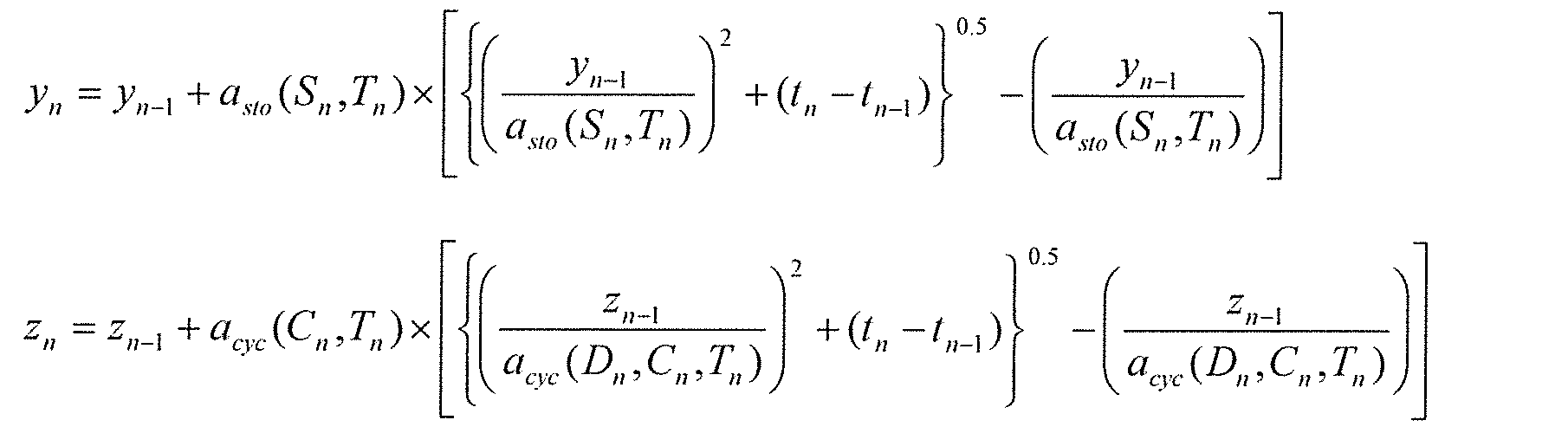
次に、上記実施の形態1の変形例1について、説明する。上記実施の形態1では、履歴取得部110は、例えば1秒のサンプリング周期で蓄電素子200の充放電履歴を取得し、取得した当該充放電履歴を充放電履歴データ151に書き込んでいくこととした。この場合、長期間にわたって蓄電素子200の充放電履歴を取得し続けると、充放電履歴データ151には、膨大な量の充放電履歴が書き込まれることとなる。
次に、上記実施の形態1の変形例2について、説明する。上記実施の形態1では、経時劣化情報及び通電劣化情報は劣化情報データ152に予め書き込まれており、この経時劣化情報及び通電劣化情報を用いて、蓄電素子の状態を推定することとした。これに対し、本変形例では、劣化情報データ152に書き込まれた経時劣化情報及び通電劣化情報を補正し、補正後の経時劣化情報及び通電劣化情報を用いて蓄電素子の状態を推定する。以下、本変形例について、詳細に説明する。

次に、実施の形態2について、説明する。上記実施の形態1では、1つの蓄電素子200(または組電池に含まれる複数の蓄電素子200)に対して1つの蓄電素子状態推定装置100が配置されていることとした。これに対し、本実施の形態では、複数の組電池に対して1つの蓄電素子状態推定装置100が配置される。以下、本実施の形態について、詳細に説明する。
次に、実施の形態2の変形例1について、説明する。上記実施の形態2では、管理基板500が蓄電素子状態推定装置100を有していることとした。これに対し、本変形例では、蓄電素子状態推定装置100は管理基板とは別に設けられている。以下、本変形例について、詳細に説明する。
次に、実施の形態2の変形例2について、説明する。上記実施の形態2の変形例1では、管理基板501と蓄電素子状態推定装置100とは、配線によって有線で接続されていることとした。これに対し、本変形例では、管理基板501と蓄電素子状態推定装置100とは、無線によって、双方向通信が行われる。以下、本変形例について、詳細に説明する。
100 蓄電素子状態推定装置
101 集積回路
110 履歴取得部
120 劣化情報取得部
130 劣化値推定部
140 状態推定部
150 記憶部
151 充放電履歴データ
152 劣化情報データ
200 蓄電素子
300 収容ケース
400 蓄電モジュール
410 計測基板
500、501 管理基板
Claims (13)
- 所定時点での蓄電素子の状態を推定する蓄電素子状態推定装置であって、
前記所定時点までの前記蓄電素子の充放電履歴を取得する履歴取得部と、
前記蓄電素子が非通電状態で経時的に劣化する経時劣化の劣化度合いを示す情報を経時劣化情報とし、当該経時的な劣化を除いた通電による劣化である通電劣化の劣化度合いを示す情報を通電劣化情報とし、前記蓄電素子の前記経時劣化の量を示す値を経時劣化値とし、前記蓄電素子の前記通電劣化の量を示す値を通電劣化値とし、前記充放電履歴に応じた前記経時劣化情報と前記通電劣化情報とを用いて、前記所定時点での前記経時劣化値と前記通電劣化値とを推定する劣化値推定部と、
前記経時劣化値と前記通電劣化値とを用いて、前記所定時点での前記蓄電素子の状態を推定する状態推定部と
を備える蓄電素子状態推定装置。 - さらに、
前記経時劣化情報及び前記通電劣化情報を取得する劣化情報取得部を備え、
前記履歴取得部は、前記所定時点までの複数の期間のそれぞれに対応した充放電履歴である期間別履歴を含む前記充放電履歴を取得し、
前記劣化情報取得部は、前記期間別履歴のそれぞれに応じた前記経時劣化情報及び前記通電劣化情報を取得し、
前記劣化値推定部は、前記期間別履歴のそれぞれに応じた前記経時劣化情報及び前記通電劣化情報を用いて、前記期間別履歴ごとに経時劣化値及び通電劣化値を算出し、算出した当該経時劣化値及び当該通電劣化値を前記期間別履歴の経過順に積算して、前記所定時点での前記経時劣化値及び前記通電劣化値を算出する
請求項1に記載の蓄電素子状態推定装置。 - 前記履歴取得部は、第一時点から第二時点までの期間別履歴である第一期間別履歴と、前記第二時点から第三時点までの期間別履歴である第二期間別履歴とを含む前記充放電履歴を取得し、
前記劣化情報取得部は、前記第一期間別履歴に応じた経時劣化情報である第一経時劣化情報と、前記第二期間別履歴に応じた経時劣化情報である第二経時劣化情報とを取得し、
前記劣化値推定部は、
前記第一経時劣化情報を用いて、前記第一時点から前記第二時点までの経時劣化値である第一経時劣化値を算出し、
前記第一経時劣化値の劣化が行われた状態を開始時点として、前記第二経時劣化情報を用いて、前記第二時点から前記第三時点までの経時劣化値である第二経時劣化値を算出し、
前記第一経時劣化値と前記第二経時劣化値とを加算して、前記第一時点から前記第三時点までの経時劣化値を算出する
請求項2に記載の蓄電素子状態推定装置。 - 前記履歴取得部は、前記蓄電素子に通電が行われた第四時点から第五時点までの期間別履歴である第三期間別履歴と、前記第五時点以降に前記蓄電素子に通電が行われた第六時点から第七時点までの期間別履歴である第四期間別履歴とを含む前記充放電履歴を取得し、
前記劣化情報取得部は、前記第三期間別履歴に応じた通電劣化情報である第一通電劣化情報と、前記第四期間別履歴に応じた通電劣化情報である第二通電劣化情報とを取得し、
前記劣化値推定部は、
前記第一通電劣化情報を用いて、前記第四時点から前記第五時点までの通電劣化値である第一通電劣化値を算出し、
前記第一通電劣化値の劣化が行われた状態を開始時点として、前記第二通電劣化情報を用いて、前記第六時点から前記第七時点までの通電劣化値である第二通電劣化値を算出し、
前記第一通電劣化値と前記第二通電劣化値とを加算して、前記第四時点から前記第七時点までの通電劣化値を算出する
請求項2または3に記載の蓄電素子状態推定装置。 - 前記履歴取得部は、前記蓄電素子のSOCの複数の時点における平均値である平均SOC及び当該複数の時点における変動量であるSOC変動量と、前記蓄電素子の温度の当該複数の時点における平均値である平均温度とを含む前記充放電履歴を取得し、
前記劣化値推定部は、前記充放電履歴に含まれる前記平均SOCと前記SOC変動量と前記平均温度とを用いて、前記経時劣化値と前記通電劣化値とを推定する
請求項1~4のいずれか1項に記載の蓄電素子状態推定装置。 - 前記履歴取得部は、取得した前記充放電履歴を、所定期間ごとの充放電履歴に更新する
請求項1~5のいずれか1項に記載の蓄電素子状態推定装置。 - 前記劣化値推定部は、前記充放電履歴を用いて前記経時劣化情報及び前記通電劣化情報を補正し、補正後の前記経時劣化情報及び前記通電劣化情報を用いて前記経時劣化値と前記通電劣化値とを推定する
請求項1~6のいずれか1項に記載の蓄電素子状態推定装置。 - 前記所定時点は、将来の時点であり、
前記履歴取得部は、過去の充放電履歴を取得して、当該将来の時点までの充放電履歴を推定することにより、当該将来の時点までの充放電履歴を取得し、
前記劣化値推定部は、当該将来の時点までの充放電履歴に応じた前記経時劣化情報と前記通電劣化情報とを用いて、当該将来の時点での前記経時劣化値と前記通電劣化値とを推定し、
前記状態推定部は、当該将来の時点での前記経時劣化値と前記通電劣化値とを用いて、当該将来の時点での前記蓄電素子の状態を推定する
請求項1~7のいずれか1項に記載の蓄電素子状態推定装置。 - 前記履歴取得部は、前記蓄電素子を有する蓄電装置から前記充放電履歴を受信し、
前記状態推定部は、推定した前記蓄電素子の状態を前記蓄電装置へ送信する
請求項1~8のいずれか1項に記載の蓄電素子状態推定装置。 - 複数の蓄電素子と、
前記複数の蓄電素子の所定時点での状態を推定する請求項1~9のいずれか1項に記載の蓄電素子状態推定装置と
を備える蓄電システム。 - 所定時点での蓄電素子の状態を推定する蓄電素子状態推定方法であって、
前記所定時点までの前記蓄電素子の充放電履歴を取得する履歴取得ステップと、
前記蓄電素子が非通電状態で経時的に劣化する経時劣化の劣化度合いを示す情報を経時劣化情報とし、当該経時的な劣化を除いた通電による劣化である通電劣化の劣化度合いを示す情報を通電劣化情報とし、前記蓄電素子の前記経時劣化の量を示す値を経時劣化値とし、前記蓄電素子の前記通電劣化の量を示す値を通電劣化値とし、前記充放電履歴に応じた前記経時劣化情報と前記通電劣化情報とを用いて、前記所定時点での前記経時劣化値と前記通電劣化値とを推定する劣化値推定ステップと、
前記経時劣化値と前記通電劣化値とを用いて、前記所定時点での前記蓄電素子の状態を推定する状態推定ステップと
を含む蓄電素子状態推定方法。 - 請求項11に記載の蓄電素子状態推定方法に含まれるステップをプロセッサに実行させるためのプログラム。
- 請求項12に記載のプログラムが記録された記録媒体。
Priority Applications (5)
| Application Number | Priority Date | Filing Date | Title |
|---|---|---|---|
| JP2016563502A JP6648698B2 (ja) | 2014-12-10 | 2015-12-08 | 蓄電素子状態推定装置及び蓄電素子状態推定方法 |
| CN201580073916.2A CN107209228B (zh) | 2014-12-10 | 2015-12-08 | 蓄电元件状态估计装置以及方法、蓄电系统、记录介质 |
| US15/534,766 US10557892B2 (en) | 2014-12-10 | 2015-12-08 | Energy storage device state estimation device and energy storage device state estimation method |
| AU2015358776A AU2015358776B2 (en) | 2014-12-10 | 2015-12-08 | Energy storage device state estimation device and energy storage device state estimation method |
| EP15867915.9A EP3232216B1 (en) | 2014-12-10 | 2015-12-08 | Energy storage element state estimation device and energy storage element state estimation method |
Applications Claiming Priority (4)
| Application Number | Priority Date | Filing Date | Title |
|---|---|---|---|
| JP2014250205 | 2014-12-10 | ||
| JP2014-250205 | 2014-12-10 | ||
| JP2015196290 | 2015-10-01 | ||
| JP2015-196290 | 2015-10-01 |
Publications (1)
| Publication Number | Publication Date |
|---|---|
| WO2016092811A1 true WO2016092811A1 (ja) | 2016-06-16 |
Family
ID=56107031
Family Applications (1)
| Application Number | Title | Priority Date | Filing Date |
|---|---|---|---|
| PCT/JP2015/006079 Ceased WO2016092811A1 (ja) | 2014-12-10 | 2015-12-08 | 蓄電素子状態推定装置及び蓄電素子状態推定方法 |
Country Status (6)
| Country | Link |
|---|---|
| US (1) | US10557892B2 (ja) |
| EP (1) | EP3232216B1 (ja) |
| JP (2) | JP6648698B2 (ja) |
| CN (1) | CN107209228B (ja) |
| AU (1) | AU2015358776B2 (ja) |
| WO (1) | WO2016092811A1 (ja) |
Cited By (20)
| Publication number | Priority date | Publication date | Assignee | Title |
|---|---|---|---|---|
| WO2018181609A1 (ja) * | 2017-03-29 | 2018-10-04 | 株式会社Gsユアサ | 劣化推定装置、劣化推定方法およびコンピュータプログラム |
| JP2018169394A (ja) * | 2017-03-29 | 2018-11-01 | 株式会社Gsユアサ | 劣化推定装置、劣化推定方法およびコンピュータプログラム |
| JP2018169393A (ja) * | 2017-03-29 | 2018-11-01 | 株式会社Gsユアサ | 劣化推定装置、劣化推定方法およびコンピュータプログラム |
| WO2019026142A1 (ja) * | 2017-07-31 | 2019-02-07 | 日産自動車株式会社 | 劣化状態演算方法及び劣化状態演算装置 |
| WO2019097357A1 (ja) * | 2017-11-16 | 2019-05-23 | 株式会社半導体エネルギー研究所 | 二次電池の寿命推定装置及び寿命推定方法および異常検出方法 |
| JP2019145268A (ja) * | 2018-02-19 | 2019-08-29 | 旭化成株式会社 | 非水系リチウム型蓄電素子の容量劣化率推定方法および容量劣化率推定装置、システム |
| CN110214280A (zh) * | 2016-11-17 | 2019-09-06 | 黄文罗基有限公司 | 确定电池的健康状态并提供警报 |
| WO2019181729A1 (ja) * | 2018-03-20 | 2019-09-26 | 株式会社Gsユアサ | 劣化推定装置、コンピュータプログラム及び劣化推定方法 |
| WO2019181728A1 (ja) * | 2018-03-20 | 2019-09-26 | 株式会社Gsユアサ | 劣化推定装置、コンピュータプログラム及び劣化推定方法 |
| CN110476072A (zh) * | 2017-03-29 | 2019-11-19 | 株式会社杰士汤浅国际 | 劣化估计装置、劣化估计方法和计算机程序 |
| JP2020063920A (ja) * | 2018-10-15 | 2020-04-23 | 富士通株式会社 | 劣化予測プログラム、劣化予測方法、および劣化予測装置 |
| JP2020193823A (ja) * | 2019-05-24 | 2020-12-03 | 株式会社Gsユアサ | 推定装置、推定方法及びコンピュータプログラム |
| JPWO2021085433A1 (ja) * | 2019-10-29 | 2021-05-06 | ||
| JP2021519423A (ja) * | 2018-03-28 | 2021-08-10 | ブランコ テクノロジー グループ アイピー オイBlancco Technology Group Ip Oy | 携帯電子機器のバッテリ摩耗を測定する方法及び装置 |
| WO2022014151A1 (ja) * | 2020-07-15 | 2022-01-20 | パナソニックIpマネジメント株式会社 | 情報処理方法及び情報処理装置 |
| JP2023047092A (ja) * | 2021-09-24 | 2023-04-05 | トヨタ自動車株式会社 | 電池の充電方法 |
| WO2023145024A1 (ja) * | 2022-01-28 | 2023-08-03 | 京セラ株式会社 | 蓄電池管理装置、蓄電池システム及び蓄電池管理方法 |
| WO2023188573A1 (ja) * | 2022-03-31 | 2023-10-05 | 本田技研工業株式会社 | 電池の劣化状態推定装置、劣化抑制システム、劣化状態推定方法、劣化抑制方法 |
| WO2024166450A1 (ja) * | 2023-02-09 | 2024-08-15 | 株式会社豊田中央研究所 | 情報処理システム、情報処理方法および情報処理プログラム |
| WO2024202580A1 (ja) * | 2023-03-29 | 2024-10-03 | パナソニックIpマネジメント株式会社 | 電池分析システム、電池分析方法、電池分析プログラムおよび電池分析プログラムが記載された記憶媒体 |
Families Citing this family (27)
| Publication number | Priority date | Publication date | Assignee | Title |
|---|---|---|---|---|
| US20180120382A1 (en) * | 2016-10-27 | 2018-05-03 | Motorola Solutions, Inc. | Battery capacity estimation for a battery pack |
| US20180292463A1 (en) * | 2017-04-10 | 2018-10-11 | Lear Corporation | Method and system for battery state of charge calculation |
| JP6881154B2 (ja) * | 2017-08-23 | 2021-06-02 | トヨタ自動車株式会社 | 二次電池の劣化状態推定方法および二次電池システム |
| EP3719515B1 (en) * | 2017-11-29 | 2023-11-08 | Kabushiki Kaisha Toshiba | Evaluation device, evaluation method, and computer program |
| TWI818892B (zh) * | 2017-12-27 | 2023-10-11 | 日商F S R股份有限公司 | 二次電池管理裝置及用於二次電池管理之程式製品 |
| EP3943903A4 (en) * | 2019-03-19 | 2022-05-04 | GS Yuasa International Ltd. | ESTIMATION DEVICE AND ESTIMATION METHOD |
| US11402435B1 (en) * | 2019-05-24 | 2022-08-02 | Gs Yuasa International Ltd. | Estimation apparatus, estimation method, and computer program |
| DE102019211634A1 (de) * | 2019-08-02 | 2021-02-04 | Robert Bosch Gmbh | Verfahren zum Betrieb einer elektrischen Energiespeichereinheit sowie entsprechende Vorrichtung, Computerprogramm, maschinenlesbares Speichermedium und elektrische Energiespeichereinheit |
| KR20210016795A (ko) * | 2019-08-05 | 2021-02-17 | 주식회사 엘지화학 | 에너지 허브 장치 및 에너지 관리 방법 |
| TWI744721B (zh) * | 2019-11-19 | 2021-11-01 | 廣達電腦股份有限公司 | 電池裝置及其控制方法 |
| KR102781907B1 (ko) * | 2019-11-28 | 2025-03-18 | 주식회사 엘지에너지솔루션 | 배터리 셀 이상 퇴화 진단 장치 및 방법 |
| JP7435101B2 (ja) * | 2020-03-18 | 2024-02-21 | 株式会社Gsユアサ | 推定装置、蓄電デバイス、推定方法、及びコンピュータプログラム |
| US20230275447A1 (en) * | 2020-07-01 | 2023-08-31 | Vestas Wind Systems A/S | Battery testing in operation |
| CN116134658A (zh) * | 2020-07-29 | 2023-05-16 | 松下知识产权经营株式会社 | 电池管理装置、运算系统、电池的劣化预测方法以及电池的劣化预测程序 |
| JP7405043B2 (ja) * | 2020-09-02 | 2023-12-26 | トヨタ自動車株式会社 | 二次電池の評価方法 |
| JP2022052373A (ja) * | 2020-09-23 | 2022-04-04 | 株式会社Gsユアサ | 情報処理装置、情報処理方法、及びコンピュータプログラム |
| JP7344192B2 (ja) * | 2020-12-21 | 2023-09-13 | 矢崎総業株式会社 | バッテリ制御装置 |
| CN113125984B (zh) * | 2021-03-09 | 2023-05-05 | 深圳拓邦股份有限公司 | 洗地机电池寿命计算方法、装置、洗地机 |
| KR102923163B1 (ko) * | 2021-11-10 | 2026-02-05 | 현대자동차주식회사 | 배터리 진단 장치 및 진단 방법 |
| JPWO2023090314A1 (ja) * | 2021-11-18 | 2023-05-25 | ||
| KR102916063B1 (ko) * | 2022-11-22 | 2026-01-20 | 주식회사 엘지에너지솔루션 | 배터리 soh 추정 장치 및 방법 |
| WO2024185080A1 (ja) * | 2023-03-08 | 2024-09-12 | 株式会社 東芝 | 蓄電池劣化量算出方法、蓄電池劣化量算出装置およびコンピュータプログラム |
| WO2025121144A1 (ja) * | 2023-12-07 | 2025-06-12 | パナソニックIpマネジメント株式会社 | 電池分析システム、電池分析方法、および電池分析プログラム、記録媒体 |
| CN117452234B (zh) | 2023-12-22 | 2024-08-13 | 齐鲁工业大学(山东省科学院) | 改进参数辨识与无穷算法融合的soc估计方法及系统 |
| CN117890792B (zh) * | 2024-01-04 | 2024-09-13 | 中国电子产品可靠性与环境试验研究所((工业和信息化部电子第五研究所)(中国赛宝实验室)) | 动力电池容量的预测方法、装置、计算机设备、存储介质 |
| WO2025150422A1 (ja) * | 2024-01-12 | 2025-07-17 | パナソニックIpマネジメント株式会社 | 電池分析システム、電池分析方法および電池分析プログラム |
| WO2026013424A1 (ja) * | 2024-07-12 | 2026-01-15 | 日産自動車株式会社 | 二次電池の劣化推定方法及び二次電池の劣化推定システム |
Citations (6)
| Publication number | Priority date | Publication date | Assignee | Title |
|---|---|---|---|---|
| JP2011220900A (ja) * | 2010-04-12 | 2011-11-04 | Honda Motor Co Ltd | 電池劣化推定方法、電池容量推定方法、電池容量均等化方法、および電池劣化推定装置 |
| JP2013051115A (ja) * | 2011-08-31 | 2013-03-14 | Toyota Motor Corp | 車両および車両の制御方法 |
| JP2013089424A (ja) * | 2011-10-17 | 2013-05-13 | Internatl Business Mach Corp <Ibm> | バッテリの状態予測システム、方法及びプログラム |
| JP2013181875A (ja) * | 2012-03-02 | 2013-09-12 | Honda Motor Co Ltd | 二次電池の劣化率算出方法、二次電池の寿命予測方法、二次電池の劣化率算出システムおよび二次電池の寿命予測システム |
| JP2013225397A (ja) * | 2012-04-20 | 2013-10-31 | Toyota Motor Corp | 非水二次電池の制御装置および制御方法 |
| JP2014163875A (ja) * | 2013-02-27 | 2014-09-08 | Shin Kobe Electric Mach Co Ltd | 蓄電池制御システム及びその蓄電池劣化度予測方法 |
Family Cites Families (16)
| Publication number | Priority date | Publication date | Assignee | Title |
|---|---|---|---|---|
| US8255176B2 (en) * | 2008-08-07 | 2012-08-28 | Research In Motion Limited | Systems and methods for monitoring deterioration of a rechargeable battery |
| JPWO2011004550A1 (ja) * | 2009-07-10 | 2012-12-13 | パナソニック株式会社 | サイクル数計数回路、電池パック、及び電池システム |
| JP5447282B2 (ja) * | 2010-08-11 | 2014-03-19 | 新神戸電機株式会社 | 自然エネルギー利用システム用鉛蓄電池および鉛蓄電池システム |
| JP5919525B2 (ja) * | 2011-11-22 | 2016-05-18 | パナソニックIpマネジメント株式会社 | 車両管理システム |
| JP5768001B2 (ja) * | 2012-04-23 | 2015-08-26 | 株式会社日立製作所 | 電池システムのメンテナンス管理システム及び方法 |
| JP2013253940A (ja) | 2012-06-08 | 2013-12-19 | Gs Yuasa Corp | 蓄電素子の寿命推定装置、寿命推定方法及び蓄電システム |
| JP5935524B2 (ja) | 2012-06-08 | 2016-06-15 | 株式会社Gsユアサ | 蓄電素子の劣化後容量推定装置、劣化後容量推定方法及び蓄電システム |
| JP5737232B2 (ja) * | 2012-07-12 | 2015-06-17 | トヨタ自動車株式会社 | 定置用蓄電池の余寿命判定装置 |
| JP6246539B2 (ja) * | 2012-09-20 | 2017-12-13 | 積水化学工業株式会社 | 蓄電池管理装置、蓄電池管理方法及びプログラム |
| JP2014081238A (ja) | 2012-10-15 | 2014-05-08 | Sony Corp | 電池劣化寿命推定方法、電池劣化寿命推定装置、電動車両および電力供給装置 |
| US20140114592A1 (en) * | 2012-10-22 | 2014-04-24 | Custom Electronics, Inc. | Operational monitoring of electrochemical capacitors |
| JP2013253991A (ja) | 2012-11-30 | 2013-12-19 | Gs Yuasa Corp | 蓄電素子の劣化後容量推定装置、劣化後容量推定方法及び蓄電システム |
| JP2014131412A (ja) | 2012-12-28 | 2014-07-10 | Nissan Motor Co Ltd | 電動車両制御装置及び電動車両制御方法 |
| WO2014155726A1 (ja) * | 2013-03-29 | 2014-10-02 | 株式会社日立製作所 | 電池特性推定方法、電池特性推定装置及びプログラム |
| JP2015158416A (ja) | 2014-02-24 | 2015-09-03 | 日産自動車株式会社 | 二次電池のsocの推定装置及びsocの推定方法 |
| JP6264147B2 (ja) * | 2014-03-28 | 2018-01-24 | 株式会社Gsユアサ | 蓄電素子の運転状態推定装置、運転状態推定方法及び蓄電システム |
-
2015
- 2015-12-08 AU AU2015358776A patent/AU2015358776B2/en active Active
- 2015-12-08 US US15/534,766 patent/US10557892B2/en active Active
- 2015-12-08 CN CN201580073916.2A patent/CN107209228B/zh active Active
- 2015-12-08 EP EP15867915.9A patent/EP3232216B1/en active Active
- 2015-12-08 WO PCT/JP2015/006079 patent/WO2016092811A1/ja not_active Ceased
- 2015-12-08 JP JP2016563502A patent/JP6648698B2/ja active Active
-
2019
- 2019-11-13 JP JP2019205790A patent/JP6897748B2/ja active Active
Patent Citations (6)
| Publication number | Priority date | Publication date | Assignee | Title |
|---|---|---|---|---|
| JP2011220900A (ja) * | 2010-04-12 | 2011-11-04 | Honda Motor Co Ltd | 電池劣化推定方法、電池容量推定方法、電池容量均等化方法、および電池劣化推定装置 |
| JP2013051115A (ja) * | 2011-08-31 | 2013-03-14 | Toyota Motor Corp | 車両および車両の制御方法 |
| JP2013089424A (ja) * | 2011-10-17 | 2013-05-13 | Internatl Business Mach Corp <Ibm> | バッテリの状態予測システム、方法及びプログラム |
| JP2013181875A (ja) * | 2012-03-02 | 2013-09-12 | Honda Motor Co Ltd | 二次電池の劣化率算出方法、二次電池の寿命予測方法、二次電池の劣化率算出システムおよび二次電池の寿命予測システム |
| JP2013225397A (ja) * | 2012-04-20 | 2013-10-31 | Toyota Motor Corp | 非水二次電池の制御装置および制御方法 |
| JP2014163875A (ja) * | 2013-02-27 | 2014-09-08 | Shin Kobe Electric Mach Co Ltd | 蓄電池制御システム及びその蓄電池劣化度予測方法 |
Non-Patent Citations (1)
| Title |
|---|
| See also references of EP3232216A4 * |
Cited By (42)
| Publication number | Priority date | Publication date | Assignee | Title |
|---|---|---|---|---|
| CN110214280A (zh) * | 2016-11-17 | 2019-09-06 | 黄文罗基有限公司 | 确定电池的健康状态并提供警报 |
| CN110214280B (zh) * | 2016-11-17 | 2021-10-12 | 黄文罗基有限公司 | 用于确定电池的健康状态的计算机实现的方法、设备及系统 |
| JP2018169394A (ja) * | 2017-03-29 | 2018-11-01 | 株式会社Gsユアサ | 劣化推定装置、劣化推定方法およびコンピュータプログラム |
| JP2018169393A (ja) * | 2017-03-29 | 2018-11-01 | 株式会社Gsユアサ | 劣化推定装置、劣化推定方法およびコンピュータプログラム |
| WO2018181609A1 (ja) * | 2017-03-29 | 2018-10-04 | 株式会社Gsユアサ | 劣化推定装置、劣化推定方法およびコンピュータプログラム |
| US11428747B2 (en) | 2017-03-29 | 2022-08-30 | Gs Yuasa International Ltd. | Degradation estimating device, degradation estimating method, and computer program |
| CN110476072A (zh) * | 2017-03-29 | 2019-11-19 | 株式会社杰士汤浅国际 | 劣化估计装置、劣化估计方法和计算机程序 |
| JPWO2019026142A1 (ja) * | 2017-07-31 | 2020-07-27 | 日産自動車株式会社 | 劣化状態演算方法及び劣化状態演算装置 |
| WO2019026142A1 (ja) * | 2017-07-31 | 2019-02-07 | 日産自動車株式会社 | 劣化状態演算方法及び劣化状態演算装置 |
| US11214168B2 (en) | 2017-07-31 | 2022-01-04 | Nissan Motor Co., Ltd. | Deterioration state computation method and deterioration state computation device |
| WO2019097357A1 (ja) * | 2017-11-16 | 2019-05-23 | 株式会社半導体エネルギー研究所 | 二次電池の寿命推定装置及び寿命推定方法および異常検出方法 |
| US11340306B2 (en) | 2017-11-16 | 2022-05-24 | Semiconductor Energy Laboratory Co., Ltd. | Lifetime estimation device, lifetime estimation method, and abnormality detection method of secondary battery |
| JP2019145268A (ja) * | 2018-02-19 | 2019-08-29 | 旭化成株式会社 | 非水系リチウム型蓄電素子の容量劣化率推定方法および容量劣化率推定装置、システム |
| JP7096008B2 (ja) | 2018-02-19 | 2022-07-05 | 旭化成株式会社 | 非水系リチウム型蓄電素子の容量劣化率推定方法および容量劣化率推定装置、システム |
| JP2019168453A (ja) * | 2018-03-20 | 2019-10-03 | 株式会社Gsユアサ | 劣化推定装置、コンピュータプログラム及び劣化推定方法 |
| JP2019168452A (ja) * | 2018-03-20 | 2019-10-03 | 株式会社Gsユアサ | 劣化推定装置、コンピュータプログラム及び劣化推定方法 |
| WO2019181728A1 (ja) * | 2018-03-20 | 2019-09-26 | 株式会社Gsユアサ | 劣化推定装置、コンピュータプログラム及び劣化推定方法 |
| WO2019181729A1 (ja) * | 2018-03-20 | 2019-09-26 | 株式会社Gsユアサ | 劣化推定装置、コンピュータプログラム及び劣化推定方法 |
| US11243262B2 (en) | 2018-03-20 | 2022-02-08 | Gs Yuasa International Ltd. | Degradation estimation apparatus, computer program, and degradation estimation method |
| JP7416710B2 (ja) | 2018-03-28 | 2024-01-17 | ブランコ テクノロジー グループ アイピー オイ | 携帯電子機器のバッテリ摩耗を測定する方法及び装置 |
| JP2021519423A (ja) * | 2018-03-28 | 2021-08-10 | ブランコ テクノロジー グループ アイピー オイBlancco Technology Group Ip Oy | 携帯電子機器のバッテリ摩耗を測定する方法及び装置 |
| JP2020063920A (ja) * | 2018-10-15 | 2020-04-23 | 富士通株式会社 | 劣化予測プログラム、劣化予測方法、および劣化予測装置 |
| JP7119882B2 (ja) | 2018-10-15 | 2022-08-17 | 富士通株式会社 | 劣化予測プログラム、劣化予測方法、および劣化予測装置 |
| JP2020193823A (ja) * | 2019-05-24 | 2020-12-03 | 株式会社Gsユアサ | 推定装置、推定方法及びコンピュータプログラム |
| JP7354586B2 (ja) | 2019-05-24 | 2023-10-03 | 株式会社Gsユアサ | 推定装置、推定方法及びコンピュータプログラム |
| US12571850B2 (en) | 2019-10-29 | 2026-03-10 | Kyocera Corporation | Storage battery management device, storage battery system,and storage battery management method |
| WO2021085433A1 (ja) * | 2019-10-29 | 2021-05-06 | 京セラ株式会社 | 蓄電池管理装置、蓄電池システム、及び蓄電池管理方法 |
| JPWO2021085433A1 (ja) * | 2019-10-29 | 2021-05-06 | ||
| JP7387754B2 (ja) | 2019-10-29 | 2023-11-28 | 京セラ株式会社 | 蓄電池管理装置、蓄電池システム、及び蓄電池管理方法 |
| WO2022014151A1 (ja) * | 2020-07-15 | 2022-01-20 | パナソニックIpマネジメント株式会社 | 情報処理方法及び情報処理装置 |
| JP7519625B2 (ja) | 2020-07-15 | 2024-07-22 | パナソニックIpマネジメント株式会社 | 情報処理方法及び情報処理装置 |
| JP2022018264A (ja) * | 2020-07-15 | 2022-01-27 | パナソニックIpマネジメント株式会社 | 情報処理方法及び情報処理装置 |
| JP2023047092A (ja) * | 2021-09-24 | 2023-04-05 | トヨタ自動車株式会社 | 電池の充電方法 |
| JP7636310B2 (ja) | 2021-09-24 | 2025-02-26 | トヨタ自動車株式会社 | 電池の充電方法 |
| WO2023145024A1 (ja) * | 2022-01-28 | 2023-08-03 | 京セラ株式会社 | 蓄電池管理装置、蓄電池システム及び蓄電池管理方法 |
| WO2023188573A1 (ja) * | 2022-03-31 | 2023-10-05 | 本田技研工業株式会社 | 電池の劣化状態推定装置、劣化抑制システム、劣化状態推定方法、劣化抑制方法 |
| JPWO2023188573A1 (ja) * | 2022-03-31 | 2023-10-05 | ||
| JP7675927B2 (ja) | 2022-03-31 | 2025-05-13 | 本田技研工業株式会社 | 電池の劣化状態推定装置、劣化抑制システム、劣化状態推定方法、劣化抑制方法 |
| WO2024166450A1 (ja) * | 2023-02-09 | 2024-08-15 | 株式会社豊田中央研究所 | 情報処理システム、情報処理方法および情報処理プログラム |
| JP2024113242A (ja) * | 2023-02-09 | 2024-08-22 | 株式会社豊田中央研究所 | 情報処理システム、情報処理方法および情報処理プログラム |
| JP7652200B2 (ja) | 2023-02-09 | 2025-03-27 | 株式会社豊田中央研究所 | 情報処理システム、情報処理方法および情報処理プログラム |
| WO2024202580A1 (ja) * | 2023-03-29 | 2024-10-03 | パナソニックIpマネジメント株式会社 | 電池分析システム、電池分析方法、電池分析プログラムおよび電池分析プログラムが記載された記憶媒体 |
Also Published As
| Publication number | Publication date |
|---|---|
| JPWO2016092811A1 (ja) | 2017-09-28 |
| EP3232216A4 (en) | 2018-08-08 |
| JP6897748B2 (ja) | 2021-07-07 |
| US10557892B2 (en) | 2020-02-11 |
| EP3232216A1 (en) | 2017-10-18 |
| AU2015358776A1 (en) | 2017-06-29 |
| AU2015358776B2 (en) | 2020-07-02 |
| JP6648698B2 (ja) | 2020-02-14 |
| US20170328957A1 (en) | 2017-11-16 |
| EP3232216B1 (en) | 2020-09-02 |
| CN107209228A (zh) | 2017-09-26 |
| JP2020042036A (ja) | 2020-03-19 |
| CN107209228B (zh) | 2020-07-31 |
Similar Documents
| Publication | Publication Date | Title |
|---|---|---|
| JP6897748B2 (ja) | 蓄電素子状態推定装置及び蓄電素子状態推定方法 | |
| JP6237643B2 (ja) | 蓄電素子の劣化後性能推定装置、劣化後性能推定方法及び蓄電システム | |
| US11079212B2 (en) | Circuitry and techniques for determining swelling of a battery/cell and adaptive charging circuitry and techniques based thereon | |
| JP6372490B2 (ja) | 蓄電素子の寿命推定装置、寿命推定方法及び蓄電システム | |
| US10088529B2 (en) | Apparatus for estimating state of hybrid secondary battery and method thereof | |
| JP5874543B2 (ja) | 蓄電素子の寿命推定装置、寿命推定方法及び蓄電システム | |
| EP3657190A1 (en) | Estimation device, power storage device, estimation method, and computer program | |
| JP2012122817A (ja) | 非水電解質二次電池の可逆容量推定方法、寿命予測方法、可逆容量推定装置、寿命予測装置及び蓄電システム | |
| WO2015146034A1 (ja) | 蓄電素子の運転状態推定装置、運転状態推定方法及び蓄電システム | |
| JP6565675B2 (ja) | 蓄電素子の劣化状態検知装置、劣化状態検知方法及び蓄電システム | |
| JP6390335B2 (ja) | 蓄電素子の性能低下検知装置、性能低下検知方法及び蓄電システム | |
| JP6773195B2 (ja) | 蓄電システム及びコンピュータプログラム | |
| JP6607079B2 (ja) | 蓄電素子状態推定装置及び蓄電素子状態推定方法 | |
| JP6206031B2 (ja) | 蓄電素子の寿命推定装置、寿命推定方法及び蓄電システム | |
| JP2013253940A (ja) | 蓄電素子の寿命推定装置、寿命推定方法及び蓄電システム | |
| JP5935524B2 (ja) | 蓄電素子の劣化後容量推定装置、劣化後容量推定方法及び蓄電システム | |
| JP6642099B2 (ja) | 蓄電素子状態推定装置及び蓄電素子状態推定方法 |
Legal Events
| Date | Code | Title | Description |
|---|---|---|---|
| 121 | Ep: the epo has been informed by wipo that ep was designated in this application |
Ref document number: 15867915 Country of ref document: EP Kind code of ref document: A1 |
|
| ENP | Entry into the national phase |
Ref document number: 2016563502 Country of ref document: JP Kind code of ref document: A |
|
| REEP | Request for entry into the european phase |
Ref document number: 2015867915 Country of ref document: EP |
|
| WWE | Wipo information: entry into national phase |
Ref document number: 15534766 Country of ref document: US |
|
| NENP | Non-entry into the national phase |
Ref country code: DE |
|
| ENP | Entry into the national phase |
Ref document number: 2015358776 Country of ref document: AU Date of ref document: 20151208 Kind code of ref document: A |