WO2016092817A1 - ヘッドフォン - Google Patents
ヘッドフォン Download PDFInfo
- Publication number
- WO2016092817A1 WO2016092817A1 PCT/JP2015/006090 JP2015006090W WO2016092817A1 WO 2016092817 A1 WO2016092817 A1 WO 2016092817A1 JP 2015006090 W JP2015006090 W JP 2015006090W WO 2016092817 A1 WO2016092817 A1 WO 2016092817A1
- Authority
- WO
- WIPO (PCT)
- Prior art keywords
- speaker unit
- main
- axis
- user
- housing
- Prior art date
- Legal status (The legal status is an assumption and is not a legal conclusion. Google has not performed a legal analysis and makes no representation as to the accuracy of the status listed.)
- Ceased
Links
Images





Classifications
-
- H—ELECTRICITY
- H04—ELECTRIC COMMUNICATION TECHNIQUE
- H04R—LOUDSPEAKERS, MICROPHONES, GRAMOPHONE PICK-UPS OR LIKE ACOUSTIC ELECTROMECHANICAL TRANSDUCERS; ELECTRIC HEARING AIDS; PUBLIC ADDRESS SYSTEMS
- H04R1/00—Details of transducers, loudspeakers or microphones
- H04R1/10—Earpieces; Attachments therefor ; Earphones; Monophonic headphones
- H04R1/1058—Manufacture or assembly
- H04R1/1066—Constructional aspects of the interconnection between earpiece and earpiece support
-
- H—ELECTRICITY
- H04—ELECTRIC COMMUNICATION TECHNIQUE
- H04R—LOUDSPEAKERS, MICROPHONES, GRAMOPHONE PICK-UPS OR LIKE ACOUSTIC ELECTROMECHANICAL TRANSDUCERS; ELECTRIC HEARING AIDS; PUBLIC ADDRESS SYSTEMS
- H04R1/00—Details of transducers, loudspeakers or microphones
- H04R1/20—Arrangements for obtaining desired frequency or directional characteristics
- H04R1/22—Arrangements for obtaining desired frequency or directional characteristics for obtaining desired frequency characteristic only
- H04R1/26—Spatial arrangements of separate transducers responsive to two or more frequency ranges
-
- H—ELECTRICITY
- H04—ELECTRIC COMMUNICATION TECHNIQUE
- H04R—LOUDSPEAKERS, MICROPHONES, GRAMOPHONE PICK-UPS OR LIKE ACOUSTIC ELECTROMECHANICAL TRANSDUCERS; ELECTRIC HEARING AIDS; PUBLIC ADDRESS SYSTEMS
- H04R1/00—Details of transducers, loudspeakers or microphones
- H04R1/10—Earpieces; Attachments therefor ; Earphones; Monophonic headphones
- H04R1/1008—Earpieces of the supra-aural or circum-aural type
-
- H—ELECTRICITY
- H04—ELECTRIC COMMUNICATION TECHNIQUE
- H04R—LOUDSPEAKERS, MICROPHONES, GRAMOPHONE PICK-UPS OR LIKE ACOUSTIC ELECTROMECHANICAL TRANSDUCERS; ELECTRIC HEARING AIDS; PUBLIC ADDRESS SYSTEMS
- H04R1/00—Details of transducers, loudspeakers or microphones
- H04R1/10—Earpieces; Attachments therefor ; Earphones; Monophonic headphones
- H04R1/1058—Manufacture or assembly
- H04R1/1075—Mountings of transducers in earphones or headphones
-
- H—ELECTRICITY
- H04—ELECTRIC COMMUNICATION TECHNIQUE
- H04R—LOUDSPEAKERS, MICROPHONES, GRAMOPHONE PICK-UPS OR LIKE ACOUSTIC ELECTROMECHANICAL TRANSDUCERS; ELECTRIC HEARING AIDS; PUBLIC ADDRESS SYSTEMS
- H04R1/00—Details of transducers, loudspeakers or microphones
- H04R1/10—Earpieces; Attachments therefor ; Earphones; Monophonic headphones
- H04R1/1091—Details not provided for in groups H04R1/1008 - H04R1/1083
-
- H—ELECTRICITY
- H04—ELECTRIC COMMUNICATION TECHNIQUE
- H04R—LOUDSPEAKERS, MICROPHONES, GRAMOPHONE PICK-UPS OR LIKE ACOUSTIC ELECTROMECHANICAL TRANSDUCERS; ELECTRIC HEARING AIDS; PUBLIC ADDRESS SYSTEMS
- H04R5/00—Stereophonic arrangements
- H04R5/033—Headphones for stereophonic communication
- H04R5/0335—Earpiece support, e.g. headbands or neckrests
Definitions
- This disclosure relates to headphones.
- Headphone is an example of a device that outputs sound.
- the headphones are used by being connected to a device having a sound signal output function, such as a sound reproducing device or a television receiving device (hereinafter abbreviated as “TV”).
- TV television receiving device
- Headphones generally include two speaker housings for right and left ears, and a headband to be worn on the user's head.
- the speaker housing includes a main speaker unit that outputs sound therein and a support member that supports the main speaker unit.
- the main speaker unit includes a diaphragm and a voice coil.
- the headband is composed of a long member bent in an arc shape. Then, two speaker housings are connected to both ends of the headband, one at each end.
- Non-Patent Document 1 discloses a technology related to sound quality improvement in a speaker system using two speakers.
- This disclosure provides a headphone that can improve the quality of sound heard by a user.
- the headphone in the present disclosure includes a speaker housing and a headband.
- the speaker housing includes a main speaker unit and a support member that supports the main speaker unit.
- the headband is connected to a speaker's head and connected to the user's head.
- the support member has a posture in which the angle of the main surface of the main speaker unit with respect to the main surface of the support member is 10 degrees or more and 30 degrees or less so that the main surface of the main speaker unit faces the earlobe of the user. Support the unit.
- the headphone in the present disclosure includes a speaker housing and a headband.
- the speaker housing includes a main speaker unit and a support member that supports the main speaker unit.
- the headband is connected to a speaker's head and connected to the user's head.
- two points estimated as positions of the user's two eardrums are set as two reference points, and an axis connecting the two reference points is set as a first axis.
- An axis passing through the reference point and perpendicular to the first axis and parallel to the front-rear direction of the user's head is defined as the second axis.
- the support member is configured so that the main speaker unit is rotated around the second axis so that the main axis of the main speaker unit passes through the reference point and is inclined at an angle of 10 degrees to 30 degrees with respect to the first axis. It is supported at a position rotated from one axis in the direction of the user's head.
- the headphones according to the present disclosure can improve the quality of the sound heard by the user.
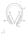
- FIG. 1 is a perspective view schematically showing an example of the appearance of a headphone according to Embodiment 1.
- FIG. FIG. 2 is a front view schematically showing an example of the appearance of the headphones in the first embodiment.
- FIG. 3 is a side view schematically showing an example of the appearance of the headphones in the first embodiment.
- FIG. 4 is a side view schematically showing an example of the appearance of the headphones in the first embodiment.
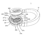
- FIG. 5 is a perspective view schematically showing an example of the configuration of the speaker housing in the first embodiment.
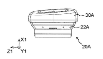
- FIG. 6A is a side view schematically showing an example of the configuration of the speaker housing in the first exemplary embodiment.
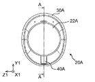
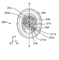
- FIG. 6B is a rear view schematically showing an example of the configuration of the speaker housing in the first exemplary embodiment.
- FIG. 6C is a side view schematically showing an example of the configuration of the speaker housing in the first exemplary embodiment.
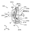
- FIG. 6D is a cross-sectional view schematically showing an example of the configuration of the speaker housing in the first exemplary embodiment.
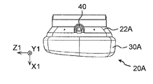
- FIG. 6E is a front view schematically showing an example of the configuration of the speaker housing in the first exemplary embodiment.
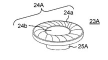
- FIG. 7 is a perspective view schematically showing an example of the configuration of the main speaker unit in the first embodiment.
- FIG. 8 is a front view schematically showing an example of the arrangement positions of the diaphragm and the sub speaker unit of the main speaker unit in the first embodiment.
- FIG. 9 is a top view schematically showing an example of the arrangement positions of the diaphragm and the sub speaker unit of the main speaker unit in the first embodiment.
- the main axis of the main speaker unit is the first axis. It has been considered that the sound quality of the sound heard by the user (hereinafter also simply referred to as “sound quality”) is improved by arranging the speakers so as to be arranged on a horizontal plane including the axis.
- Non-Patent Document 1 it is verified whether or not there is a speaker position advantageous for improving sound quality at a position other than the horizontal plane including the first axis.
- the average localization error is the difference (error) between the direction of the sound source recognized by the subject and the direction of the actual sound source.
- the listener of the sound feels that the sound image has become clearer and feels that the realism of the sound has been improved.
- the subject's head is fixed so that the axis connecting the top of the head and the jaw is in the vertical direction (the direction of gravity). Then, sound is generated from a sound source moving on a vertical plane including the first axis, and the average localization error is measured.
- the average eardrum position of a user wearing headphones is about 30 mm away from the main surface of the speaker housing included in the headphones (the surface formed by the portion of the housing to which the ear pad is attached) in the first axis direction. It is the position.
- the inventors have found that, in the relationship between the diaphragm and the eardrum, adjusting the angle of the diaphragm can obtain substantially the same effect as changing the position of the speaker.
- FIG. 1 is a perspective view schematically showing an example of the appearance of the headphone 1 in the first embodiment.
- FIG. 2 is a front view schematically showing an example of the appearance of the headphone 1 in the first embodiment.
- FIG. 3 is a side view schematically showing an example of the appearance of the headphone 1 in the first embodiment.
- FIG. 3 shows a side view of the headphone 1 as viewed from the right-ear speaker housing 20B side.
- FIG. 4 is a side view schematically showing an example of the appearance of the headphone 1 in the first embodiment.
- FIG. 4 shows a side view of the headphone 1 as viewed from the left ear speaker housing 20A side.
- the headphone 1 includes a headband 10, a left-ear speaker housing 20A, and a right-ear speaker housing 20B, as shown in FIGS.
- the headband 10 is a member attached to the user's head.
- the headband 10 includes a long member bent in an arc shape so that the headband 10 can be worn on a human head.
- One end of the long member is connected to a speaker housing 20A that is in contact with the left ear of a user wearing the headphones 1 (hereinafter also simply referred to as “user”), and the other end.
- a speaker housing 20B that is in contact with the right ear of the user is connected to the section.
- the headband 10 may further include other members such as a head pad and a microphone (both not shown) that are in contact with the top of the user's head.
- other members such as a head pad and a microphone (both not shown) that are in contact with the top of the user's head.
- the configuration example in which the speaker housing 20A and the speaker housing 20B are connected to the end portions of the long member is shown.
- the speaker housing 20A and the speaker housing 20B may be connected to positions having an interval.
- the speaker housing 20A and the speaker housing 20B may be fixedly provided on a long member, or the connection positions of the speaker housing 20A and the speaker housing 20B on the long member may be set. You may be comprised so that it can change.
- the headband 10 shown in the present embodiment is configured so that the length of the long member can be changed (see FIG. 5).
- the size of the head and the position of the ear differ depending on the user.
- the length of the headband 10 is adjustable, the speaker housing 20A and the speaker housing 20B can be adjusted and arranged at the position of the user's ear.
- the structure which can adjust the length of the headband 10 is realizable with the mechanism generally used, and is not an essential structure in this indication.
- a signal line (not shown) for transmitting a sound signal is arranged from the speaker housing 20A side to the speaker housing 20B.
- the speaker housing 20A and the speaker housing 20B will be described.
- the connector 40 is provided only in the speaker housing 20A.
- the connector 40 is a member for connecting a sound signal transmission cord (not shown).
- the speaker housing 20A and the speaker housing 20B have substantially the same configuration. Therefore, in the following description, the speaker housing 20A will be mainly described, and a detailed description of the speaker housing 20B will be omitted.
- Speaker housing 20A and speaker housing 20B are members that come into contact with the ears of the user wearing headphones 1.
- Each of the speaker housing 20A and the speaker housing 20B accommodates a main speaker unit and a sub speaker unit therein.
- the main speaker unit and the sub speaker unit reproduce sound corresponding to a sound signal output from a sound reproduction device (not shown).
- the sound signal may be transmitted from the sound reproduction device to the headphones 1 by connecting the headphones 1 and the sound reproduction device with a sound signal transmission cord (not shown), or the headphones 1 and the sound reproduction device. May be transmitted by wireless connection.
- the speaker housing 20A is configured for the user's left ear
- the speaker housing 20B is configured for the right ear. That is, the headphone 1 is configured so that the left ear sound is output from the speaker housing 20A and the right ear sound is output from the speaker housing 20B. Therefore, when the headphones 1 are worn on the user's head, the speaker housing 20A is disposed so as to cover the user's left ear, and the speaker housing 20B is disposed so as to cover the user's right ear.
- the state is a normal use state of the headphones 1.
- FIG. 5 is a perspective view schematically showing an example of the configuration of the speaker housing 20A in the first embodiment.
- the headphone 1 is configured such that the speaker housing 20 ⁇ / b> A and the speaker housing 20 ⁇ / b> B rotate with respect to the headband 10.
- FIG. 5 shows a state where the speaker housing 20 ⁇ / b> A and the speaker housing 20 ⁇ / b> B are rotated with respect to the headband 10.
- FIG. 6A is a side view schematically showing an example of the configuration of the speaker housing 20A in the first exemplary embodiment.
- FIG. 6B is a rear view schematically showing an exemplary configuration of speaker housing 20A in the first exemplary embodiment.
- FIG. 6C is a side view schematically showing an example of the configuration of speaker housing 20A in the first exemplary embodiment.
- FIG. 6D is a cross-sectional view schematically showing an example of the configuration of the speaker housing 20A in the first exemplary embodiment.
- FIG. 6E is a front view schematically showing an example of the configuration of speaker housing 20A in the first exemplary embodiment.
- 6D is a cross-sectional view taken along line AA in FIG. 6B.
- the side that contacts the ear is the front surface
- the surface facing the front surface is the back surface
- the surface sandwiched between the front surface and the back surface substantially perpendicular to the front surface and the back surface.
- axis X1, the axis Y1, and the axis Z1 defined as follows are used for convenience.
- the axis X1 is a first axis B (see FIG. 6D) that connects two points (two reference points) estimated as the positions of the user's two eardrums. Note that only the reference point of the left ear is shown in FIG. 6D. It is a parallel axis. In other words, the axis X1 is an axis substantially parallel to the horizontal direction of the user's head, that is, the direction connecting the left ear and the right ear when the headphones 1 are worn by the user.
- the axis Y1 is an axis substantially parallel to the longitudinal direction of the ear shell of the user's ear.
- the axis Y1 is an axis that is perpendicular to the axis X1 and substantially parallel to the vertical direction of the user's head (the axis connecting the head and chin) when the headphones 1 are worn on the user. It is.
- the axis Y1 may be paraphrased as being an axis that is perpendicular to the axis X1 and substantially parallel to the axis that connects the tragus and the earlobe.
- the axis Z1 is an axis perpendicular to the axis X1 and the axis Y1. In other words, the axis Z1 is an axis substantially parallel to the front-rear direction of the user's head when the headphones 1 are worn by the user.
- the speaker housing 20A includes a main speaker unit 23A that outputs sound and a support member that supports the main speaker unit 23A.
- the speaker housing 20A includes an ear pad 30A, a housing 22A, a baffle plate 21A as an example of a support member, a protector 27A, and a main speaker unit 23A.
- the speaker housing 20B includes an ear pad 30B, a housing 22B, a baffle plate 21B as an example of a support member, a protector 27B, a main speaker unit 23B, and a protector 271B (not shown). And a sub-speaker unit 26B (not shown; only the reference is provided).
- the configuration of the speaker housing 20B is substantially the same as the configuration of the speaker housing 20A except for the connector 40.
- the ear pad 30 ⁇ / b> A is a member that covers the ears of the user who wears the headphones 1. As shown in FIG. 6A to FIG. 6E, the ear pad 30A has a torus shape (annular shape) that can surround the ears (side surfaces).
- the ear pad 30A is configured to be attachable to and detachable from the baffle plate 21A as shown in FIG. 6D as an example.
- the ear pad 30A includes a fitting portion 301A that fits into a groove portion 201A formed along the outer peripheral portion of the baffle plate 21A on the side in contact with the baffle plate 21A.
- the configurations of the housing 22A, the baffle plate 21A, the protector 27A, and the protector 271A will be described later.
- the ear pad 30A can be attached along the outer peripheral portion of the baffle plate 21A by fitting the fitting portion 301A into the groove portion 201A of the baffle plate 21A. With this configuration, the user's ear can be placed in a space surrounded by the ear pad 30A, the baffle plate 21A, and the protector 27A and the protector 271A that cover the opening of the baffle plate 21A.
- the ear pad 30A may be fixedly attached to the baffle plate 21A.
- the ear pad 30A has a cross-sectional shape of a surface parallel to the radial direction such that the cross-sectional area increases toward the earlobe side and the cross-sectional area decreases toward the top of the head, as shown in an example in FIG. 6D. Is formed.
- a human head has a shape that gradually decreases in width from the temporal region to the chin. Therefore, with this configuration, the main surface of the baffle plate 21 ⁇ / b> A (the main surface of the protector 27 ⁇ / b> A) can be maintained at an angle close to perpendicular to the first axis B.
- the ear pad 30A is made of a soft resin material and can be deformed according to the shape around the user's ear. Thereby, the adhesiveness between the ear pad 30A and the baffle plate 21A and the adhesiveness between the ear pad 30A and the user's ear (around the ear) can be improved. That is, the above-described space (the space surrounding the user's ear) can be brought closer to a closed space (sealed space) with few gaps.
- the housing 22A and the baffle plate 21A are an example of a support member that supports the main speaker unit 23A in a state of being housed in a space formed by the housing 22A and the baffle plate 21A.
- the housing 22A is connected to the headband 10.
- the housing 22A is a concave member in which an opening is formed in an oval shape (a shape including an oval shape, an oval shape, etc.) as shown in FIGS. 6A to 6E.
- the main speaker unit storage portion 222 is in the space formed between the baffle plate 21A and the housing 22A, and the main speaker unit 23A on the back side of the protector 27A is disposed. Area.
- the opening of the baffle plate 21A in which the main speaker unit storage unit 222 is provided is formed in a region near the top (including the top of the user when the headphones 1 are worn by the user) including the center of the baffle plate 21A. Has been.
- the main speaker unit storage portion 222 is surrounded by a flat plate portion 220 as shown in FIG.
- the main speaker unit housing portion 222 is formed so as to cover a part and side surfaces of the main surface of the main speaker unit 23A. Therefore, the shape and size of the main speaker unit storage portion 222 are determined according to the shape and size of the main speaker unit 23A.
- the main speaker unit storage portion 222 is formed so that a part thereof protrudes more to the ear side than the surface (ear side surface) of the flat plate portion 220.
- the main speaker unit storage unit 222 includes a sound output unit 222a corresponding to the opening of the baffle plate 21A and an inclined unit 222c.
- the diaphragm 24A of the main speaker unit 23A is disposed on the back side.
- a protector 27 ⁇ / b> A is disposed in the sound output unit 222 a of the main speaker unit storage unit 222.
- the inclined portion 222c is a cylindrical member that constitutes a side surface portion of the sound output portion 222a.
- the inclined portion 222c is so formed that the height when the headphone 1 is worn by the user is higher with respect to the flat plate portion 220 toward the top of the head and on the side opposite to the top of the head (the earlobe side). ) So that the height relative to the flat plate portion 220 becomes lower.
- the sound output part 222a which covers the upper part of the inclination part 222c will be in the state inclined with respect to the baffle board 21A (flat plate part 220). This is because the main speaker unit 23A is provided with an angle with respect to the first axis B, as will be described later.
- the main speaker unit 23A is partially covered with the sound output part 222a and the inclined part 222c.
- the sub speaker unit storage portion 223 is a space inside the space formed between the baffle plate 21A and the housing 22A, and is a region where the sub speaker unit 26A is disposed on the back side of the protector 271A. Therefore, the shape and size of the sub speaker unit storage portion 223 are determined according to the shape and size of the sub speaker unit 26A. As shown in FIG. 6E, the opening of the baffle plate 21A in which the sub speaker unit storage portion 223 is provided is lower than the main speaker unit 23A (the user's chin when the headphones 1 are worn by the user). And the frontal side of the center line A (the face side of the user when the headphones 1 are worn by the user). The center line A is a line parallel to the axis Y1 that substantially passes through the center of the speaker housing 20A (or baffle plate 21A).
- the auxiliary speaker unit storage section 223 includes a sound output section 223a corresponding to the opening of the baffle plate 21A and an inclined section 223c.
- the sound output unit 223a is provided with a diaphragm (not shown) of the sub speaker unit 26A on the back side.
- a protector 271A is disposed in the sound output unit 223a of the sub speaker unit storage unit 223.
- the inclined portion 223c is a cylindrical member that constitutes a side surface portion of the sound output portion 223a.
- Inclined portion 223c is such that, when headphone 1 is worn by the user, the height when the flat plate portion 220 is used as a reference is lowered toward the top of the head, and the side opposite to the top of the head (the earlobe side) ) So that the height with respect to the flat plate portion 220 becomes higher.
- the sound output part 223a which covers the upper part of the inclination part 223c will be in the state inclined with respect to the flat plate part 220.
- the baffle plate 21A is a member attached so as to cover the opening of the housing 22A.
- the baffle plate 21 ⁇ / b> A includes a flat plate portion 220 and a fixing portion 221. Further, two openings are provided in the baffle plate 21A.
- FIG. 5 shows a state where the ear pad 30A is removed from the baffle plate 21A.
- the flat plate portion 220 is an oval plate-like member whose outline is formed in substantially the same shape as the opening of the housing 22A.
- the flat plate portion 220 is attached to the opening of the housing 22A.
- the surface (surface exposed to the ear side) of the flat plate portion 220 is the main surface of the baffle plate 21A.
- the flat plate part 220 is provided with two openings.
- One of the two openings is covered with a protector 27A for protecting the main speaker unit 23A, and the other of the two openings is covered with a protector 271A for protecting the sub speaker unit 26A. It has been broken.
- One opening is an opening for attaching the main speaker unit 23A, and the center of the main speaker unit 23A is above the first axis B (the top of the user when the headphones 1 are worn by the user). Side) (see FIG. 6D).
- the other opening is an opening for attaching the sub speaker unit 26A, and the center of the sub speaker unit 26A is below the first axis B (the user's chin when the headphones 1 are worn by the user). Side) (see FIG. 6D).
- baffle plate 21A and protector 271A are integrally formed, but they may be formed as separate members.
- the fixing portion 221 has a hole for passing a screw for fixing the baffle plate 21A to the housing 22A.
- the baffle plate 21A is fixed to the housing 22A by screwing the hole through the screw to the housing 22A.
- annular groove 201A for attaching the ear pad 30A is formed in the baffle plate 21A along the outer peripheral portion.
- the surface defined by the groove 201A or the opening of the housing 22A is the main surface of the baffle plate 21A, that is, the main surface of the support member.
- the main surface of the support member may be a surface that intersects at least a part of the baffle plate 21A and is perpendicular to the first axis B or intersects at an angle close to the first axis B. .
- the baffle plate 21A may be formed of a material having vibration damping properties, for example, a material including PLA (polylactide, polylactide).
- the protector 27A is a member that covers one of the two openings of the baffle plate 21A, and is attached to the front surface (ear side) of the main speaker unit 23A as shown in an example in FIG. 6D. As shown in FIG. 5, the protector 27A is provided in the sound output unit 222a of the main speaker unit storage unit 222 that stores the main speaker unit 23A, and functions as a protective member for the main speaker unit 23A.
- the protector 27A is a disk-shaped member in which a plurality of slits 27a are formed as shown in FIGS. 5 and 6E.
- the protector 27A is formed so that the surface of a diaphragm 24A described later can be seen from the outside.
- the protector 27A includes a circular slit, six slits having substantially the same shape (fan shape) on the first circle surrounding the circular slit from the outside, and the first circle. Six slits of substantially the same shape (fan shape) on the second larger circle and six of substantially the same shape (fan shape) on the third circle larger than the second circle And a slit.
- these slits are collectively referred to as slits 27a.
- the protector 27A has a shape in which four torus plates of different sizes arranged on substantially the same plane are connected by six long bridge portions extending in the radial direction. Yes. The angles between each of the six bridges are substantially all the same. Further, the size of the protector 27A is determined according to the size of the diaphragm 24A constituting the main speaker unit 23A.
- a protector 271A is provided as a protector that covers the other of the two openings of the baffle plate 21A. As shown in FIG. 6D, the protector 271A is provided in the sound output unit 223a of the sub speaker unit storage unit 223 that stores the sub speaker unit 26A, and functions as a protection member for the sub speaker unit 26A.
- the protector 271A is a convex member (see FIG. 6D) in which a plurality of slits 271a are formed as shown in FIG. 5 and FIG. 6E.
- the sound output unit 223a is formed so that a diaphragm (not shown) of the sub speaker unit 26A can be visually recognized from the outside.
- the protector 271A is formed with a circular slit and three slits of substantially the same shape (sector shape) on the concentric circle formed so as to surround the circular slit. Yes.
- these slits are collectively referred to as slits 271a.
- the protector 271A has a shape in which two torus plates of different sizes arranged on different planes are connected to each other by three long bridge portions extending in the radial direction. The angles between each of the three bridges are substantially all the same.
- the size of the protector 271A is determined according to the size of a diaphragm (not shown) constituting the sub speaker unit 26A.
- the main speaker unit 23A is a dynamic speaker unit, and is configured to be able to reproduce sound in a band of 4 Hz to 50 kHz, for example.
- the main speaker unit 23A is, for example, a speaker unit having a diameter of 50 mm, and is a speaker unit mounted on a housing 22A disposed on the left ear of a user wearing the headphones 1.
- the configuration of the main speaker unit 23B mounted on the housing 22B disposed in the right ear of the user is substantially the same as the configuration of the main speaker unit 23A except that the connector 40 is not provided.
- FIG. 7 is a perspective view schematically showing an example of the configuration of the main speaker unit 23A in the first embodiment.
- the main speaker unit 23A includes a diaphragm 24A, a voice coil (not shown), and a magnetic member 25A.
- the drive current corresponding to the sound signal from the sound reproducing device flows through the voice coil, so that the voice coil vibrates.
- the diaphragm 24A is configured to vibrate according to the vibration of the voice coil. Then, when the diaphragm 24A vibrates, the sound corresponding to the sound signal is reproduced by the main speaker unit 23A.
- the diaphragm 24A is composed of a planar film having a substantially circular outline.
- the diaphragm 24A is formed in a shape in which a hemispherical vibrating portion 24b is combined at the center of the edge portion 24a of a semi-torus shape (a shape obtained by cutting a hollow torus-like member along a plane perpendicular to the rotation axis). Has been.
- the protruding directions of the edge portion 24a and the vibrating portion 24b are the same.
- a surface (a plane including the contour portion of the vibration portion 24b) defined by the contour portion of the vibration portion 24b in the vibration plate 24A is defined as a main surface of the vibration plate 24A.
- the main surface of the diaphragm 24A may be a plane substantially perpendicular to the axis of the edge portion 24a or the axis of the vibration portion 24b.
- the axis of the edge portion 24a is an axis substantially passing through the center of the edge portion 24a and substantially perpendicular to the edge portion 24a.
- the axis of the vibration part 24b is an axis substantially passing through the center of the vibration part 24b and substantially perpendicular to the vibration part 24b.
- the edge portion 24a and the vibrating portion 24b are configured such that the axis of the edge portion 24a and the axis of the vibrating portion 24b substantially coincide with each other.
- the main surface of the diaphragm 24A is substantially the main surface of the main speaker unit 23A.
- the main surface of the main speaker unit 23A intersects at least a part of the members constituting the main speaker unit 23A and is a surface substantially perpendicular to the axis of the edge portion 24a or the axis of the vibration portion 24b of the diaphragm 24A. There may be.
- FIG. 8 is a front view schematically showing an example of arrangement positions of the diaphragm 24A and the sub speaker unit 26A of the main speaker unit 23A in the first embodiment.
- FIG. 8 is a diagram schematically showing the cross section shown in FIG. 6D in a simplified manner.
- FIG. 8 schematically shows the arrangement positions of the flat plate portion 220, the diaphragm 24A, and the sub speaker unit 26A when the headphones 1 worn by the user are viewed from the user's face side.
- the user's ear is indicated by a dotted line for convenience.
- FIG. 8 is only a schematic diagram for explaining the positional relationship (angle, etc.) of each member, and the dimensional ratio of the user's ear, flat plate portion 220, diaphragm 24A, and sub-speaker unit 26A shown in the drawing. And angles do not represent actual dimensional ratios or angles.
- the first axis B, the second axis E, the third axis F, the main axis C, and the main axis D defined as follows are used.
- the first axis B is an axis connecting two estimated reference points and the position of the user's eardrum, and is an axis parallel to the axis X1.
- FIG. 8 only the reference point PL estimated as the position of the eardrum of the user's left ear is shown, and the reference point estimated as the position of the eardrum of the right ear is not shown.
- the second axis E is an axis that passes through the first axis B and is parallel to the axis Z1.
- the second axis E is an axis substantially parallel to the lateral direction of the user's ear shell, that is, an axis substantially parallel to the longitudinal direction of the user's head.
- the third axis F is an axis that passes through the main surface of the baffle plate 21A (the ear-side surface of the flat plate portion 220) and is substantially parallel to the longitudinal direction (axis Y1) of the ear shell.
- the main axis C is a main axis of the main speaker unit 23A, and is also a main axis of the diaphragm 24A.
- the main axis of the diaphragm 24A is an axis that substantially passes through the center of the diaphragm 24A and is substantially perpendicular to the main surface of the diaphragm 24A.
- the main axis of the main speaker unit 23A is an axis that passes through substantially the center of the main speaker unit 23A and is substantially perpendicular to the main surface of the main speaker unit 23A.
- the main speaker unit 23A is configured such that the main axis of the diaphragm 24A and the main axis of the main speaker unit 23A substantially coincide with each other.
- the diaphragm 24A is configured such that the main axis C is substantially equal to the axis of the funnel-shaped edge portion 24a constituting the diaphragm 24A.
- the main speaker unit 23A is installed in the speaker housing 20A so that the main axis C passes through the reference point PL.
- the main axis D is the main axis of the sub speaker unit 26A, and is also the main axis of the diaphragm (not shown) of the sub speaker unit 26A.
- the main axis of the diaphragm of the sub speaker unit 26A is an axis substantially passing through the center of the diaphragm of the sub speaker unit 26A and substantially perpendicular to the main surface of the diaphragm of the sub speaker unit 26A.
- the main axis of the sub speaker unit 26A is an axis that passes through substantially the center of the sub speaker unit 26A and is substantially perpendicular to the main surface of the sub speaker unit 26A.
- the sub speaker unit 26A is configured such that the main axis of the sub speaker unit 26A and the main axis of the diaphragm of the sub speaker unit 26A substantially coincide with each other.
- the sub speaker unit 26A is installed in the speaker housing 20A so that the main axis D passes through the reference point PL.
- the main surface of the main speaker unit 23A (that is, the main surface of the diaphragm 24A) is in the direction of the eardrum of the user wearing the headphones 1 (that is, the reference point PL direction). It is arranged in a state inclined toward the user's earlobe so as to face.
- the main speaker unit 23A has a main surface of the baffle plate 21A that is an example of a support member (that is, the ear-side surface of the flat plate portion 220. The surface indicated by the third axis F in FIG. 8).
- the main surface (main surface of the diaphragm 24A) is attached to the speaker housing 20A so that the angle ⁇ is 10 degrees or more and 30 degrees or less (20 degrees ⁇ 10 degrees).
- This angle is an angle set based on experiments so that the average localization error is small.
- the main surface of the main speaker unit 23A is substantially equal to the main surface of the diaphragm 24A as described above. Therefore, the above-described configuration can be rephrased as follows.
- the main speaker unit 23A is supported around the second axis E at a position rotated in the direction of the user's head from the first axis B so as to be inclined at an angle.
- the sub-speaker unit 26A is a dynamic type speaker unit, and is configured to be able to reproduce sound in a band different from that of the main speaker unit 23A, for example, sound in a band of 50 kHz to 100 kHz.
- the sub speaker unit 26 ⁇ / b> A is a speaker unit mounted on a housing 22 ⁇ / b> A disposed on the left ear of the user wearing the headphones 1.
- sub-speaker unit 26B (not shown) mounted on the housing 22B disposed in the user's right ear is substantially the same as the sub-speaker unit 26A.
- the auxiliary speaker unit 26A is on the baffle plate 21A below the main speaker unit 23A (the user's chin side when the headphones 1 are attached to the user), and It is arranged on the frontal side of the center line A (the face side of the user when the headphones 1 are worn by the user).
- the sub speaker unit 26A can be arranged at a position where it does not interfere with the main speaker unit 23A.
- the sub speaker unit 26A is installed in the speaker housing 20A so that the main axis D intersects the main axis C of the main speaker unit 23A at the reference point PL.
- the main axis D of the sub speaker unit 26A is also the main axis of the diaphragm (not shown) of the sub speaker unit 26A.
- the diaphragm of the sub speaker unit 26A is smaller than the diaphragm 24A of the main speaker unit 23A, but its shape is substantially the same as the diaphragm 24A.
- the main surface of the sub speaker unit 26A (that is, the main surface of the diaphragm of the sub speaker unit 26A) is in the direction of the eardrum of the user wearing the headphones 1 (that is, the reference point). It is arranged in a state inclined toward the user's top of the head so as to face (PL direction).
- the sub-speaker unit 26A is supported around the second axis E at a position rotated from the first axis B toward the user's earlobe so as to be inclined at an angle.
- the plug 40 is a member for connecting a cord for transmitting a sound signal output from the sound reproducing device to the headphones 1 to the headphones 1.
- the plug 40 is provided in the housing 22A.
- FIG. 9 is a top view schematically showing an example of the arrangement positions of the diaphragm 24A and the sub speaker unit 26A of the main speaker unit 23A in the first embodiment.
- FIG. 9 is a diagram schematically showing the arrangement position of the diaphragm 24A in a simplified manner.
- the axis G is an axis on the X1Z1 plane that passes through the main surface of the baffle plate 21A (the ear-side surface of the flat plate portion 220), and is substantially orthogonal to the third axis F shown in FIG.
- This is an axis substantially parallel to the zigzag axis Z1.
- the axis H is an axis on the X1Z1 plane passing through the main surface of the diaphragm 24A, and is an axis substantially orthogonal to the third axis F shown in FIG.
- FIG. 9 schematically shows the arrangement positions of the flat plate portion 220 and the diaphragm 24A when the headphone 1 attached to the user is viewed from the top of the user's head.
- the user's head is indicated by a dotted line for convenience.
- FIG. 9 is only a schematic diagram for explaining the positional relationship (angle etc.) of each member, and the dimension ratio and angle of the user's head, flat plate portion 220, and diaphragm 24A shown in the drawing are It does not indicate actual dimensional ratios or angles.
- the diaphragm 24A that is, the main speaker unit 23A
- the diaphragm 24A may be further rotated around the third axis F. .
- the rotation direction of the diaphragm 24A (main speaker unit 23A) having the third axis F as the rotation axis is such that the end of the diaphragm 24A on the user's face side approaches the user's face.
- the end of the user's occipital side in 24A is away from the user's occipital region.
- the angle ⁇ of the axis H with respect to the axis G is preferably set to about 0 to 15 degrees in accordance with the angle of the ear shell (the angle of the ear shell with respect to the temporal region).
- sub-speaker unit 26A may also be rotated around the third axis F in the same manner as the diaphragm 24A.
- the headphones include the speaker housing and the headband.
- the speaker housing includes a main speaker unit and a support member that supports the main speaker unit.
- the headband is connected to a speaker's head and connected to the user's head.
- the support member has a posture in which the angle of the main surface of the main speaker unit with respect to the main surface of the support member is 10 degrees or more and 30 degrees or less so that the main surface of the main speaker unit faces the earlobe of the user. Support the unit.
- the headphone includes a speaker housing and a headband.
- the speaker housing includes a main speaker unit and a support member that supports the main speaker unit.
- the headband is connected to a speaker's head and connected to the user's head.
- two points estimated as positions of the user's two eardrums are set as two reference points, and an axis connecting the two reference points is set as a first axis.
- An axis passing through the reference point and perpendicular to the first axis and parallel to the front-rear direction of the user's head is defined as the second axis.
- the support member is configured so that the main speaker unit is rotated around the second axis so that the main axis of the main speaker unit passes through the reference point and is inclined at an angle of 10 degrees to 30 degrees with respect to the first axis. It is supported at a position rotated from one axis in the direction of the user's head.
- the headphone 1 is an example of a headphone.
- Each of the speaker housing 20A and the speaker housing 20B is an example of a speaker housing.
- the headband 10 is an example of a headband.
- Each of the main speaker unit 23A and the main speaker unit 23B is an example of a main speaker unit.
- Each of the housing 22A, the housing 22B, the baffle plate 21A, and the baffle plate 21B is an example of a support member.
- the reference point PL is an example of a reference point.
- the first axis B is an example of the first axis.
- the second axis E is an example of the second axis.
- the main speaker unit may have a diaphragm.
- the support member may support the main speaker unit in a posture in which the angle of the main axis of the diaphragm with respect to the main surface of the support member is 60 degrees or greater and 80 degrees or less.
- the diaphragm 24A is an example of a diaphragm.
- the baffle plate 21A is configured so that the main surface of the baffle plate 21A is supported so that the main surface of the main speaker unit 23A faces the earlobe side of the user wearing the headphones 1.
- the main speaker unit 23A is supported in such a posture that the angle ⁇ of the main surface of the main speaker unit 23A with respect to an example of the main surface of the member is 20 ° ⁇ 10 ° (10 ° to 30 °).
- the baffle plate 21A has an angle ⁇ of the main axis C of the diaphragm 24A with respect to the main surface of the baffle plate 21A is 70 degrees ⁇ 10 degrees (60 degrees or more and 80 degrees or less). In this posture, the main speaker unit 23A is supported.
- the main speaker unit 23A is supported around the second axis E at a position rotated from the first axis B in the direction of the user's head so as to be inclined at the following angle.
- the headphone 1 configured in this way can output the sound output from the main speaker unit 23A toward the user's eardrum from the direction that can reduce the average localization error. Therefore, compared with a headphone in which a diaphragm is arranged at a position where the rotation angle around the second axis E is 0 degree, the sound quality (realism) of sound heard by the user who uses the headphone 1 is improved. And high-quality three-dimensional sound can be realized.
- the support member may be a baffle plate to which the main speaker unit is attached.
- each of the baffle plate 21A and the baffle plate 21B is an example of a baffle plate.
- the baffle plate 21A functions as a support member.
- the headphone may further include a sub speaker unit.
- the support member may support the main speaker unit and the sub speaker unit in an inclined state so that the main axis of the main speaker unit and the main axis of the sub speaker unit intersect at a predetermined reference point.
- a point estimated as the position of the user's eardrum may be set as the reference point.
- each of the sub speaker unit 26A and the sub speaker unit 26B is an example of a sub speaker unit.
- the reference point PL is an example of a reference point.
- the speaker housing 20A includes the sub speaker unit 26A.
- the speaker housing 20A is configured such that the main axis D of the sub speaker unit 26A intersects the main axis C of the main speaker unit 23A at a predetermined reference point.
- the speaker housing 20A can output the sound from the sub speaker unit 26A toward a predetermined reference point, specifically, a position estimated as the position of the user's eardrum. . Therefore, the headphone 1 having this configuration improves not only the sound output from the main speaker unit 23A but also the sound output from the sub speaker unit 26A, the sound quality (realism) of the sound heard by the user. Can be made.
- the support member supports the sub speaker unit at a position closer to the user's frontal side than the center line of the baffle plate to which the main speaker unit is attached or the center line of the protector covering the opening of the baffle plate. Also good.
- the center line of the baffle plate or protector may be a line parallel to the longitudinal direction of the user's ear shell.
- each of the protector 27A and the protector 27B is an example of a protector.
- the sub-speaker unit 26A is substantially aligned with the center line A of the baffle plate 21A (substantially passing through the center of the baffle plate 21A in the longitudinal direction of the user's ear shell. It is arranged at a position on the frontal side of the user from a parallel line.
- the sub speaker unit 26A can be arranged at a position where it does not interfere with the main speaker unit 23A.
- the speaker housing 20A will be described, but the speaker housing 20B is the same.
- the configuration example in which the main speaker unit 23A is attached to the baffle plate 21A has been described, but the main speaker unit 23A may be attached to the housing 22A.
- the support member is the housing 22A
- the main surface of the support member is the main surface of the housing 22A.
- the main surface of the housing 22A is, for example, a flat surface including a housing opening (a surface parallel to the surface of the flat plate portion 220 of the baffle plate 21A), but is not limited thereto.
- the main surface of the housing 22A may be a surface parallel to a plane including the opening of the housing 22A.
- the configuration example in which the speaker housing 20A includes the sub speaker unit 26A has been described, but the sub speaker unit 26A is not an essential configuration of the present disclosure.
- the speaker housing 20A may not include the sub speaker unit 26A.
- the speaker housing 20A may include a plurality of sub speaker units 26A.
- the plurality of sub-speaker units 26A may be configured such that each main axis intersects with the main axis of the main speaker unit 23A at the corresponding reference point PL.
- the configuration example in which the main speaker unit 23A and the sub speaker unit 26A are dynamic speaker units has been described, but the present disclosure is not limited thereto.
- the main speaker unit 23A and the sub speaker unit 26A may be other types of speaker units. Further, the main speaker unit 23A and the sub speaker unit 26A may be different types of speaker units.
- the headphones 1 are wired to other devices by a sound signal transmission cord (not shown)
- the headphones 1 are wirelessly connected to other devices. It may be connected.
- the directions of “up, down, left and right, front and rear” used in the description in the first embodiment and the modification are relative for convenience and are not absolute.
- the “center” used in the description in the present embodiment may be the center of gravity, or the intersection of the major axis and the minor axis in an ellipse. Or it may be a point defined by other definitions.
- “center”, “vertical”, “parallel” and the like used in the description in the present embodiment are not strict, and an error within a range in which a desired effect can be obtained is allowed.
- the present disclosure can be applied to headphones connected to a sound reproduction device or a device having a sound signal output function such as a TV.
Landscapes
- Engineering & Computer Science (AREA)
- Physics & Mathematics (AREA)
- Acoustics & Sound (AREA)
- Signal Processing (AREA)
- Manufacturing & Machinery (AREA)
- Health & Medical Sciences (AREA)
- Otolaryngology (AREA)
- Headphones And Earphones (AREA)
Abstract
Description
従来は、利用者の2つの鼓膜の位置と推定される2点を2つの基準点とし、それら2つの基準点を結ぶ軸を第一軸とした場合に、主スピーカユニットの主軸が、第一軸を含む水平面上に配置されるようにスピーカが配置されることで、利用者に聴取される音の音質(以下、単に「音質」ともいう)が良くなる、と考えられていた。
以下、図1~図8を用いて、実施の形態を説明する。本実施の形態では、上述した知見に基づいて、スピーカ筐体内に搭載された振動板の角度を調整している。
図1は、実施の形態1におけるヘッドフォン1の外観の一例を模式的に示す斜視図である。
ヘッドバンド10は、利用者の頭部に装着される部材である。
次に、スピーカ筐体20Aおよびスピーカ筐体20Bについて説明する。なお、本実施の形態に示すヘッドフォン1は、スピーカ筐体20Aだけにコネクタ40が設けられている。コネクタ40は、音信号伝送用のコード(図示せず)を接続するための部材である。しかし、この点を除き、スピーカ筐体20Aとスピーカ筐体20Bとは、実質的に同じ構成である。したがって、以下の説明では、主にスピーカ筐体20Aについて説明し、スピーカ筐体20Bについての詳細な説明は省略する。
イヤーパッド30Aは、ヘッドフォン1を装着する利用者の耳を包み込むように覆う部材である。イヤーパッド30Aは、図6A~図6Eに一例を示すように、耳(の側面)を囲むことができるトーラス状(円環状)の形状を有している。
ハウジング22Aおよびバッフル板21Aは、主スピーカユニット23Aを、ハウジング22Aおよびバッフル板21Aにより形成される空間の内部に収納した状態で支持する支持部材の一例である。ハウジング22Aは、ヘッドバンド10に接続されている。ハウジング22Aは、図6A~図6Eに一例を示すように、開口部がオーバル状(卵形および楕円形等を含む形状)に形成された凹状部材である。
主スピーカユニット収納部222は、図6Dに一例を示すように、バッフル板21Aとハウジング22Aとの間に形成される空間内部であって、プロテクタ27Aの裏面側の、主スピーカユニット23Aが配置される領域である。主スピーカユニット収納部222が設けられるバッフル板21Aの開口部は、バッフル板21Aの中央部を含む頭頂部(ヘッドフォン1が利用者に装着されたときの利用者の頭頂部)寄りの領域に形成されている。
副スピーカユニット収納部223は、バッフル板21Aとハウジング22Aとの間に形成される空間内部であって、プロテクタ271Aの裏面側の、副スピーカユニット26Aが配置される領域である。したがって、副スピーカユニット収納部223の形状および大きさは、副スピーカユニット26Aの形状および大きさに応じて決定される。副スピーカユニット収納部223が設けられるバッフル板21Aの開口部は、図6Eに一例を示すように、主スピーカユニット23Aよりも下側(ヘッドフォン1が利用者に装着されたときの利用者の顎側)で、かつ中心線Aよりも前頭部側(ヘッドフォン1が利用者に装着されたときの利用者の顔側)に形成されている。なお、中心線Aは、実質的にスピーカ筐体20A(またはバッフル板21A)の中心を通る、軸Y1に平行な線である。
バッフル板21Aは、ハウジング22Aの開口部を覆うように取り付けられる部材である。
プロテクタ27Aは、バッフル板21Aの2つの開口部のうちの一方を覆う部材であり、図6Dに一例を示すように、主スピーカユニット23Aの前面(耳側)に取り付けられる。プロテクタ27Aは、図5に一例を示すように、主スピーカユニット23Aを収納する主スピーカユニット収納部222の音出力部222aに設けられ、主スピーカユニット23Aの保護部材として機能する。
主スピーカユニット23Aは、ダイナミック型のスピーカユニットであり、例えば、4Hz~50kHzの帯域の音を再現可能に構成されている。主スピーカユニット23Aは、例えば、直径50mmのスピーカユニットであり、ヘッドフォン1を装着した利用者の左耳に配置されるハウジング22Aに搭載されるスピーカユニットである。
副スピーカユニット26Aは、ダイナミック型のスピーカユニットであり、主スピーカユニット23Aとは異なる帯域の音、例えば、50kHz~100kHzの帯域の音を再現可能に構成されている。副スピーカユニット26Aは、ヘッドフォン1を装着した利用者の左耳に配置されるハウジング22Aに搭載されるスピーカユニットである。
プラグ40は、音再生装置から出力される音信号をヘッドフォン1に伝送するコードを、ヘッドフォン1に接続するための部材である。本実施の形態では、プラグ40は、ハウジング22Aに設けられている。
図9は、実施の形態1における主スピーカユニット23Aの振動板24Aおよび副スピーカユニット26Aの配置位置の一例を模式的に示す上面図である。なお、図9は、振動板24Aの配置位置を単純化して模式的に示した図である。
以上のように、本実施の形態において、ヘッドフォンは、スピーカ筐体と、ヘッドバンドと、を備える。スピーカ筐体は、主スピーカユニットと、主スピーカユニットを支持する支持部材と、を有する。ヘッドバンドは、スピーカ筐体が接続され、利用者の頭部に装着される。そして、支持部材は、主スピーカユニットの主面が利用者の耳垂側に向くように、支持部材の主面に対する主スピーカユニットの主面の角度が10度以上30度以下となる姿勢で主スピーカユニットを支持する。
以上のように、本出願において開示する技術の例示として、実施の形態1および変形例を説明した。しかしながら、本開示における技術は、これに限定されず、変更、置き換え、付加、省略等を行った実施の形態にも適用できる。また、上記実施の形態1および変形例で説明した各構成要素を組み合わせて、新たな実施の形態とすることも可能である。
10 ヘッドバンド
20A,20B スピーカ筐体
21A,21B バッフル板
22A,22B ハウジング
23A,23B 主スピーカユニット
24A 振動板
25A 磁性部材
26A,26B 副スピーカユニット
27A,27B,271A,271B プロテクタ
27a,271a スリット
30A,30B イヤーパッド
201A 溝部
220 平板部
221 固定部
222 主スピーカユニット収納部
222a,223a 音出力部
222c,223c 傾斜部
223 副スピーカユニット収納部
301A 嵌合部
A 中心線
B 第一軸
C,D 主軸
E 第二軸
F 第三軸
G,H,X1,Y1,Z1 軸
Claims (7)
- 主スピーカユニットと前記主スピーカユニットを支持する支持部材とを有するスピーカ筐体と、
前記スピーカ筐体が接続され、利用者の頭部に装着されるヘッドバンドと、
を備えるヘッドフォンであって、
前記支持部材は、前記主スピーカユニットの主面が前記利用者の耳垂側に向くように、前記支持部材の主面に対する前記主スピーカユニットの主面の角度が10度以上30度以下となる姿勢で前記主スピーカユニットを支持する、
ヘッドフォン。 - 前記主スピーカユニットは、振動板を有し、
前記支持部材は、前記支持部材の主面に対する前記振動板の主軸の角度が60度以上80度以下となる姿勢で前記主スピーカユニットを支持する、
請求項1に記載のヘッドフォン。 - 前記支持部材は、前記主スピーカユニットが取り付けられるバッフル板である、
請求項1に記載のヘッドフォン。 - 副スピーカユニットをさらに備え、
前記支持部材は、前記主スピーカユニットの主軸と前記副スピーカユニットの主軸とが所定の基準点で交わるように、前記主スピーカユニットおよび前記副スピーカユニットを、それぞれ傾斜させた状態で支持する、
請求項1に記載のヘッドフォン。 - 前記利用者の鼓膜の位置と推定される点が前記基準点に設定された、
請求項4に記載のヘッドフォン。 - 前記支持部材は、前記副スピーカユニットを、前記主スピーカユニットが取り付けられるバッフル板の中心線または前記バッフル板の開口部を覆うプロテクタの中心線よりも前記利用者の前頭部側の位置で支持し、前記バッフル板または前記プロテクタの中心線は、前記利用者の耳殻の縦方向に平行な線である、
請求項4に記載のヘッドフォン。 - 主スピーカユニットと前記主スピーカユニットを支持する支持部材とを有するスピーカ筐体と、
前記スピーカ筐体が接続され、利用者の頭部に装着されるヘッドバンドと、
を備えるヘッドフォンであって、
前記利用者の2つの鼓膜の位置と推定される2点を2つの基準点とするとともに前記2つの基準点を結ぶ軸を第一軸とし、
前記基準点を通り、前記第一軸に垂直かつ前記利用者の頭部の前後方向に平行な軸を第二軸とし、
前記支持部材は、前記主スピーカユニットの主軸が、前記基準点を通りかつ前記第一軸に対して10度以上30度以下の角度で傾斜するように、前記主スピーカユニットを、前記第二軸回りに、前記第一軸から前記利用者の頭頂部方向に回転させた位置で支持する、
ヘッドフォン。
Priority Applications (4)
| Application Number | Priority Date | Filing Date | Title |
|---|---|---|---|
| JP2016563504A JPWO2016092817A1 (ja) | 2014-12-09 | 2015-12-08 | ヘッドフォン |
| US15/306,070 US9936281B2 (en) | 2014-12-09 | 2015-12-08 | Headphone |
| EP15866546.3A EP3232680B1 (en) | 2014-12-09 | 2015-12-08 | Headphone |
| CN201580022753.5A CN106256137B (zh) | 2014-12-09 | 2015-12-08 | 头戴式耳机 |
Applications Claiming Priority (2)
| Application Number | Priority Date | Filing Date | Title |
|---|---|---|---|
| JP2014-249286 | 2014-12-09 | ||
| JP2014249286 | 2014-12-09 |
Publications (1)
| Publication Number | Publication Date |
|---|---|
| WO2016092817A1 true WO2016092817A1 (ja) | 2016-06-16 |
Family
ID=56107033
Family Applications (1)
| Application Number | Title | Priority Date | Filing Date |
|---|---|---|---|
| PCT/JP2015/006090 Ceased WO2016092817A1 (ja) | 2014-12-09 | 2015-12-08 | ヘッドフォン |
Country Status (5)
| Country | Link |
|---|---|
| US (1) | US9936281B2 (ja) |
| EP (1) | EP3232680B1 (ja) |
| JP (1) | JPWO2016092817A1 (ja) |
| CN (1) | CN106256137B (ja) |
| WO (1) | WO2016092817A1 (ja) |
Cited By (2)
| Publication number | Priority date | Publication date | Assignee | Title |
|---|---|---|---|---|
| US9807493B1 (en) | 2016-04-21 | 2017-10-31 | Human, Incorporated | Attachment apparatus |
| WO2025182346A1 (ja) * | 2024-02-29 | 2025-09-04 | ソニーグループ株式会社 | ヘッドホン |
Families Citing this family (30)
| Publication number | Priority date | Publication date | Assignee | Title |
|---|---|---|---|---|
| JP1578050S (ja) * | 2016-09-28 | 2017-06-05 | ||
| USD837763S1 (en) * | 2017-03-15 | 2019-01-08 | Onkyo Corporation | Headphones |
| CN208353535U (zh) * | 2017-03-17 | 2019-01-08 | 宁波升亚电子有限公司 | 扬声装置和头戴式耳机 |
| JP1594991S (ja) * | 2017-07-21 | 2018-01-15 | ||
| WO2019223556A1 (zh) * | 2018-05-25 | 2019-11-28 | 宁波升亚电子有限公司 | 近耳式音响装置和音效再现方法 |
| USD876392S1 (en) * | 2018-07-26 | 2020-02-25 | ZhongTian DingSheng (Shenzhen) Industry Co., Ltd. | Headphone |
| KR102637019B1 (ko) | 2018-11-05 | 2024-02-16 | 삼성전자 주식회사 | 기울어진 진동판을 갖는 스피커 모듈 및 상기 스피커 모듈을 포함하는 전자 장치 |
| US10911855B2 (en) | 2018-11-09 | 2021-02-02 | Vzr, Inc. | Headphone acoustic transformer |
| JP7167788B2 (ja) * | 2019-03-19 | 2022-11-09 | 株式会社Jvcケンウッド | イヤーマフ |
| USD908110S1 (en) * | 2019-04-16 | 2021-01-19 | ZhongTian DingSheng (Shenzhen) Industry Co., Ltd. | Headphone |
| USD901439S1 (en) * | 2019-04-28 | 2020-11-10 | Guihua Chen | Headset |
| JP7266872B2 (ja) * | 2019-09-13 | 2023-05-01 | 株式会社オーディオテクニカ | ヘッドホンとイヤーマフ |
| CN111669684B (zh) * | 2020-06-19 | 2021-10-15 | 菏泽韩升元电子股份有限公司 | 环绕型耳机扬声器组件及其制造方法 |
| USD947153S1 (en) * | 2020-11-18 | 2022-03-29 | Shenzhen Thousandshores Technology Co., Ltd. | Kid headphone |
| USD980189S1 (en) * | 2020-12-02 | 2023-03-07 | Yi Zhao (Shenzhen) Co., Limited | Audio headset |
| USD978825S1 (en) * | 2021-01-04 | 2023-02-21 | Harman International Industries, Incorporated | Headphone |
| JP2022118360A (ja) * | 2021-02-02 | 2022-08-15 | ヤマハ株式会社 | 音の拡散器および拡散方法 |
| USD974325S1 (en) * | 2021-03-31 | 2023-01-03 | Shenzhen Jiuhu Technology Co., Limited | Headphone |
| USD1001094S1 (en) * | 2021-08-04 | 2023-10-10 | Shenzhen Chaosupao Electronic Technology Co., Ltd | Headphone |
| USD1002575S1 (en) * | 2021-08-04 | 2023-10-24 | Shenzhen Chaosupao Electronic Technology Co., Ltd | Headphone |
| USD1037200S1 (en) * | 2021-09-23 | 2024-07-30 | James Ghormley | Headphone |
| USD1010610S1 (en) * | 2022-01-19 | 2024-01-09 | Transound Electronics Co., Ltd. | Headset |
| USD986851S1 (en) * | 2023-02-01 | 2023-05-23 | Hong Kong Juyan Technology Co., Limited | Wireless headphone |
| USD1001098S1 (en) * | 2023-05-18 | 2023-10-10 | Song WAN | Replacement headband cushion kit |
| DE102023126742A1 (de) * | 2023-09-29 | 2025-04-03 | Axel Grell | Muschelkopfhörer und Kopfhörermuschel |
| USD1134288S1 (en) * | 2024-07-09 | 2026-07-14 | Shenzhen Jiuhu Technology Co., Limited | Headphones |
| USD1127763S1 (en) * | 2024-07-09 | 2026-05-26 | Shenzhen Jiuhu Technology Co., Limited | Headphones |
| USD1074641S1 (en) * | 2024-11-15 | 2025-05-13 | Shenzhen Apwil Electronic Co., Ltd. | Headphone |
| USD1079674S1 (en) * | 2025-01-17 | 2025-06-17 | Zhaoqing Junfeng Electronics Co., Ltd | Headset |
| USD1074642S1 (en) * | 2025-01-24 | 2025-05-13 | Peng Jiang | Headphone |
Citations (3)
| Publication number | Priority date | Publication date | Assignee | Title |
|---|---|---|---|---|
| JPS63268395A (ja) * | 1987-04-27 | 1988-11-07 | Matsushita Electric Ind Co Ltd | イヤ−パツド |
| WO2013005775A1 (ja) * | 2011-07-05 | 2013-01-10 | Koizumi Isamu | 受話器及び送受話器 |
| JP2014512751A (ja) * | 2011-03-29 | 2014-05-22 | ウルトラゾーネ アーゲー | 最適化された音響放射を伴うヘッドホン |
Family Cites Families (6)
| Publication number | Priority date | Publication date | Assignee | Title |
|---|---|---|---|---|
| DE2345850A1 (de) * | 1973-09-12 | 1975-03-20 | Neckarelz Mikrofonbau | Kopfhoerer fuer mehrkanaliges, insbesondere quadrophonisches hoeren |
| JP4030545B2 (ja) * | 2002-09-27 | 2008-01-09 | ボストン アコースティックス, インコーポレーティッド | ラウドスピーカ |
| FR2854537A1 (fr) * | 2003-04-29 | 2004-11-05 | Hong Cong Tuyen Pham | Casque acoustique pour la restitution spatiale d'un son. |
| US20050238189A1 (en) * | 2004-04-23 | 2005-10-27 | Gamma Inc. | Headphone device with surround sound effect |
| US20070274548A1 (en) * | 2006-05-23 | 2007-11-29 | Jetvox Acoustic Corp. | Multi-channel headphone |
| JP2013199187A (ja) | 2012-03-23 | 2013-10-03 | Asahi Glass Co Ltd | 車両用リアガラス及びその取付方法 |
-
2015
- 2015-12-08 JP JP2016563504A patent/JPWO2016092817A1/ja active Pending
- 2015-12-08 CN CN201580022753.5A patent/CN106256137B/zh not_active Expired - Fee Related
- 2015-12-08 EP EP15866546.3A patent/EP3232680B1/en active Active
- 2015-12-08 WO PCT/JP2015/006090 patent/WO2016092817A1/ja not_active Ceased
- 2015-12-08 US US15/306,070 patent/US9936281B2/en not_active Expired - Fee Related
Patent Citations (3)
| Publication number | Priority date | Publication date | Assignee | Title |
|---|---|---|---|---|
| JPS63268395A (ja) * | 1987-04-27 | 1988-11-07 | Matsushita Electric Ind Co Ltd | イヤ−パツド |
| JP2014512751A (ja) * | 2011-03-29 | 2014-05-22 | ウルトラゾーネ アーゲー | 最適化された音響放射を伴うヘッドホン |
| WO2013005775A1 (ja) * | 2011-07-05 | 2013-01-10 | Koizumi Isamu | 受話器及び送受話器 |
Cited By (3)
| Publication number | Priority date | Publication date | Assignee | Title |
|---|---|---|---|---|
| US9807493B1 (en) | 2016-04-21 | 2017-10-31 | Human, Incorporated | Attachment apparatus |
| US10382855B2 (en) | 2016-04-21 | 2019-08-13 | Human, Incorporated | Attachment apparatus |
| WO2025182346A1 (ja) * | 2024-02-29 | 2025-09-04 | ソニーグループ株式会社 | ヘッドホン |
Also Published As
| Publication number | Publication date |
|---|---|
| US20170064436A1 (en) | 2017-03-02 |
| CN106256137A (zh) | 2016-12-21 |
| CN106256137B (zh) | 2019-09-24 |
| EP3232680A4 (en) | 2017-10-18 |
| US9936281B2 (en) | 2018-04-03 |
| EP3232680A1 (en) | 2017-10-18 |
| JPWO2016092817A1 (ja) | 2017-09-14 |
| EP3232680B1 (en) | 2020-05-13 |
Similar Documents
| Publication | Publication Date | Title |
|---|---|---|
| CN106256137B (zh) | 头戴式耳机 | |
| JP5399482B2 (ja) | 調節自在なデュアルスピーカーエレメント式インイヤー型イヤフォン | |
| CN101198194B (zh) | 耳机设备 | |
| TWI572215B (zh) | 耳機結構 | |
| CN101310557B (zh) | 电声转换器和耳机装置 | |
| WO2015064340A1 (ja) | 音声振動発生素子 | |
| WO2013088689A1 (ja) | 密閉型ヘッドフォン | |
| JP5716058B2 (ja) | インナーイヤー式イヤホン | |
| US20070092098A1 (en) | Headphones with elastic earpiece interface | |
| EP3200476B1 (en) | Headphone | |
| US20250097619A1 (en) | Headphones comprising a plurality of acoustic elements | |
| WO2020255607A1 (ja) | イヤホン | |
| KR101521320B1 (ko) | 조절식 듀얼 스피커 요소 인-이어폰 | |
| JP2017112446A (ja) | ヘッドホン用イヤパッド及びヘッドホンおよびイヤーマフ | |
| KR101123864B1 (ko) | 보빈에 의해 지지되는 압전소자 타입의 골전도 이어폰 | |
| GB2512105A (en) | Headphones | |
| WO2019058523A1 (ja) | スピーカ装置 | |
| KR101124013B1 (ko) | 다기능 이어폰 | |
| CN106878846B (zh) | 多轨立体声耳机结构 | |
| KR101614509B1 (ko) | 진동식 음향 출력장치 | |
| WO2022149254A1 (ja) | イヤーパッド、ヘッドホン、イヤーチップおよび固定部材 | |
| US12538078B2 (en) | Edge, speaker unit, microphone, and acoustic processing device | |
| KR101123867B1 (ko) | 서라운드에 의해 지지되는 압전소자 타입의 골전도 이어폰 | |
| JP2008141690A (ja) | 電気音響変換器及びイヤースピーカ装置 | |
| JP4826454B2 (ja) | イヤースピーカ装置 |
Legal Events
| Date | Code | Title | Description |
|---|---|---|---|
| 121 | Ep: the epo has been informed by wipo that ep was designated in this application |
Ref document number: 15866546 Country of ref document: EP Kind code of ref document: A1 |
|
| REEP | Request for entry into the european phase |
Ref document number: 2015866546 Country of ref document: EP |
|
| WWE | Wipo information: entry into national phase |
Ref document number: 2015866546 Country of ref document: EP |
|
| ENP | Entry into the national phase |
Ref document number: 2016563504 Country of ref document: JP Kind code of ref document: A |
|
| WWE | Wipo information: entry into national phase |
Ref document number: 15306070 Country of ref document: US |
|
| NENP | Non-entry into the national phase |
Ref country code: DE |