WO2016093252A1 - 医療用長尺体の通過性テスト装置、および医療用長尺体の通過性評価方法 - Google Patents
医療用長尺体の通過性テスト装置、および医療用長尺体の通過性評価方法 Download PDFInfo
- Publication number
- WO2016093252A1 WO2016093252A1 PCT/JP2015/084449 JP2015084449W WO2016093252A1 WO 2016093252 A1 WO2016093252 A1 WO 2016093252A1 JP 2015084449 W JP2015084449 W JP 2015084449W WO 2016093252 A1 WO2016093252 A1 WO 2016093252A1
- Authority
- WO
- WIPO (PCT)
- Prior art keywords
- medical
- hole
- passage
- load
- passability
- Prior art date
- Legal status (The legal status is an assumption and is not a legal conclusion. Google has not performed a legal analysis and makes no representation as to the accuracy of the status listed.)
- Ceased
Links
Images



Classifications
-
- G—PHYSICS
- G09—EDUCATION; CRYPTOGRAPHY; DISPLAY; ADVERTISING; SEALS
- G09B—EDUCATIONAL OR DEMONSTRATION APPLIANCES; APPLIANCES FOR TEACHING, OR COMMUNICATING WITH, THE BLIND, DEAF OR MUTE; MODELS; PLANETARIA; GLOBES; MAPS; DIAGRAMS
- G09B23/00—Models for scientific, medical, or mathematical purposes, e.g. full-sized devices for demonstration purposes
- G09B23/28—Models for scientific, medical, or mathematical purposes, e.g. full-sized devices for demonstration purposes for medicine
- G09B23/285—Models for scientific, medical, or mathematical purposes, e.g. full-sized devices for demonstration purposes for medicine for injections, endoscopy, bronchoscopy, sigmoidscopy, insertion of contraceptive devices or enemas
-
- G—PHYSICS
- G09—EDUCATION; CRYPTOGRAPHY; DISPLAY; ADVERTISING; SEALS
- G09B—EDUCATIONAL OR DEMONSTRATION APPLIANCES; APPLIANCES FOR TEACHING, OR COMMUNICATING WITH, THE BLIND, DEAF OR MUTE; MODELS; PLANETARIA; GLOBES; MAPS; DIAGRAMS
- G09B19/00—Teaching not covered by other main groups of this subclass
- G09B19/24—Use of tools
-
- G—PHYSICS
- G09—EDUCATION; CRYPTOGRAPHY; DISPLAY; ADVERTISING; SEALS
- G09B—EDUCATIONAL OR DEMONSTRATION APPLIANCES; APPLIANCES FOR TEACHING, OR COMMUNICATING WITH, THE BLIND, DEAF OR MUTE; MODELS; PLANETARIA; GLOBES; MAPS; DIAGRAMS
- G09B23/00—Models for scientific, medical, or mathematical purposes, e.g. full-sized devices for demonstration purposes
- G09B23/28—Models for scientific, medical, or mathematical purposes, e.g. full-sized devices for demonstration purposes for medicine
-
- G—PHYSICS
- G09—EDUCATION; CRYPTOGRAPHY; DISPLAY; ADVERTISING; SEALS
- G09B—EDUCATIONAL OR DEMONSTRATION APPLIANCES; APPLIANCES FOR TEACHING, OR COMMUNICATING WITH, THE BLIND, DEAF OR MUTE; MODELS; PLANETARIA; GLOBES; MAPS; DIAGRAMS
- G09B23/00—Models for scientific, medical, or mathematical purposes, e.g. full-sized devices for demonstration purposes
- G09B23/28—Models for scientific, medical, or mathematical purposes, e.g. full-sized devices for demonstration purposes for medicine
- G09B23/30—Anatomical models
- G09B23/32—Anatomical models with moving parts
-
- G—PHYSICS
- G09—EDUCATION; CRYPTOGRAPHY; DISPLAY; ADVERTISING; SEALS
- G09B—EDUCATIONAL OR DEMONSTRATION APPLIANCES; APPLIANCES FOR TEACHING, OR COMMUNICATING WITH, THE BLIND, DEAF OR MUTE; MODELS; PLANETARIA; GLOBES; MAPS; DIAGRAMS
- G09B9/00—Simulators for teaching or training purposes
Definitions
- the present invention relates to a medical elongate passability test apparatus and a medical elongate passability evaluation method performed using the medical elongate passability test apparatus.
- PTCA percutaneous transaneous coronary angioplasty
- the lesion model is made of silicon resin or the like and is a simulated reproduction of a stenosis or occlusion state of a blood vessel.
- the performance related to the passage of a medical long body such as a balloon catheter is evaluated by a sensory test conducted by a doctor using the above lesion model. Since the sensory test is based on the subjective impression of the individual, it cannot be said that the performance regarding the passability of the medical long body is accurately evaluated without variation.
- the present invention has been made in order to meet the above-described demand, and provides a medical elongate passage test apparatus that can objectively evaluate the performance of the medical elongate passage. Objective. It is another object of the present invention to provide a method for evaluating the passability of a medical long body using the medical long body passability test apparatus.
- a medical elongate body passage test apparatus that achieves the above object includes a main body portion having a hole portion through which the medical elongate body can be inserted, and the medical elongate body inserted into the hole portion. And at least one obstacle portion that hinders passage by a load (F) having a known size.
- the obstructing part protrudes into the hole part so as to be retractable from the hole part and contacts the medical elongated body, and a load acting in a direction to project the movable part into the hole part.
- a load section that loads the load.
- the medical elongate passability evaluation method that achieves the above object is a medical elongate passability evaluation method performed using the medical elongate passability test apparatus described above, wherein the hole When the medical long body inserted into the part can pass through the movable part by retreating the movable part from the hole part, it is evaluated that “it has a permeability to a load (F) whose size is known”.
- the medical elongate passability test can be performed by adjusting the load (F) that obstructs the passage of the medical elongate body. It is possible to objectively evaluate the performance of the medical elongated body without regard to the individual's subjective impression, and to improve the accuracy of the performance evaluation of the medical elongated body. Become.
- the performance of the medical long body can be objectively evaluated without depending on the subjective impression of the individual. It is possible to improve the accuracy of the performance evaluation of the medical long body.
- FIG. 2A and 2B are a front view and a rear view showing a medical elongate body permeability test apparatus.
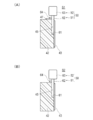
- 3A and 3B are cross-sectional views taken along line 3-3 in FIG. 2A, and FIG. 3A shows the first position where the movable portion narrows the hole.
- FIG. 3B is a cross-sectional view showing a state in which the movable portion protrudes to the second position where the hole portion is closed.
- 4 (A), 4 (B), and 4 (C) are enlarged views of a main part of FIG.
- FIG. 10 is a front view showing a medical elongate passage test apparatus according to a modification, which is a medical elongate passage test apparatus in which the axis of a hole extends in a curved shape. It is a medical elongate passage test device concerning other modifications, and is an important section enlarged view showing composition of an obstacle part.
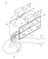
- FIG. 1 is a view showing a state where a balloon catheter 30 as a medical elongated body 30 is subjected to a permeability test using the medical elongated body permeability test apparatus 10 according to an embodiment of the present invention.
- 2 (A) and 2 (B) are a front view and a rear view showing the passability test apparatus 10 for the medical elongated body 30, and
- FIGS. 3 (A) and 3 (B) are lines 3-3 in FIG. 2 (A).
- 3A is a cross-sectional view showing a state where the movable portion 51 protrudes to the first position S1 where the hole 41 is constricted
- FIG. 3B is a view showing the movable portion.
- FIG. 4 (A), 4 (B), and 4 (C) are enlarged views of the main part of FIG. 2 (A) showing a state in which the passability test of the medical elongated body 30 is performed.
- FIG. 4B shows a state in which the distal end of the medical long body 30 has reached the movable part 51
- FIG. 4B shows a state in which the medical long body 30 has moved away from the hole part 41 and passed through the movable part 51.
- FIG. 4C is a diagram illustrating a state in which the medical long body 30 cannot pass through the movable portion 51.
- the passability test apparatus 10 (hereinafter also simply referred to as “test apparatus 10”) of the medical long body 30 is generally a hole through which the medical long body 30 can be inserted. At least one that obstructs the passage of the body portion 40 in which the portion 41 (generic name of 61, 71) and the medical elongated body 30 inserted into the hole portion 41 are loaded by a load (F) whose size is known.
- a load whose size is known.
- Two obstacles 50 protrudes into the hole part 41 so as to be retractable from the hole part 41 and contacts the medical long body 30 and a load acting in a direction in which the movable part 51 protrudes into the hole part 41.
- a load portion 52 that loads the movable portion 51.
- the end of the blood vessel model 20 can be freely connected to the hole 41, and the test apparatus 10 performs a passability test of the medical elongated body 30 inserted into the hole 41 through the blood vessel model 20. It is configured to be possible.
- a balloon catheter 30 will be described as an example of the medical long body 30. Details will be described below.
- the right front side of the test apparatus 10 is a front surface, and the opposite left hand back side is a back surface.
- the main body 40 of the test apparatus 10 is provided with a plurality of combinations of the hole 41 and the obstacle 50. As a result, the test apparatus 10 can perform a plurality of types of passability tests on one balloon catheter 30.
- a first test unit 60 (see FIG. 2A) disposed on the front side and a second test unit 70 (FIG. 2B) disposed on the back side are provided. 2 types) are provided.
- the first test part 60 has a bump-like convex part 71a in which the hole 71 protrudes toward the obstacle part 50 in that the axis of the hole 61 extends linearly, and the axis of the hole 71 is This is different from the second test portion 70 that extends partially in a curved shape.
- the first test unit 60 is different from the second test unit 70 having a pointed shape in that the portion of the obstacle 50 that contacts the balloon catheter 30 has a flat shape.
- the main body part 40 includes a base part 42, a first cover part 43 attached to the front side of the base part 42, and a second cover part 44 attached to the back side of the base part 42.
- the 1st cover part 43 and the 2nd cover part 44 are formed from the transparent body so that the situation where the balloon catheter 30 passes the obstruction part 50 can be visually recognized.
- By forming at least a part of the main body portion 40 from a transparent body it is possible to visually recognize the passage state of the balloon catheter 30 and to reliably and easily determine whether or not the balloon catheter 30 has passed.
- the movable part 51 in the first test part 60 and the second test part 70 includes movable plates 62 and 72 that are slidably provided on the main body part 40 and have known masses. Yes.
- the load unit 52 in the first test unit 60 and the second test unit 70 includes weights 63 and 73 attached to the movable plates 62 and 72 and having a known mass.
- Mass of movable plate 62 in first test unit 60 m11 [kg] Mass of weight 63 in first test unit 60: m12 [kg] Mass of movable plate 72 in second test unit 70: m21 [kg] The mass of the weight 73 in the second test unit 70 is m22 [kg].
- the obstacle unit 50 greatly increases the passage of the balloon catheter 30 inserted into the hole 61. Is inhibited by a known load (F1). Also in the second test unit 70, the obstacle unit 50 inhibits the passage of the balloon catheter 30 inserted into the hole 71 by a load (F2) whose size is known.
- F2 (m21 + m22) ⁇ G [N]
- G is a gravitational acceleration. It becomes.
- the weights 63 and 73 are not particularly limited, but for example, a plurality of weights 63 and 73 are manufactured within a range of 1 gram to 500 grams. A plurality of weights may be manufactured so that the weight difference between the weights is equal, or a plurality of weights may be manufactured so that the weight difference between the weights gradually increases. Insertion holes are formed in the lower surfaces of the weights 63 and 73. The weights 63 and 73 can be inserted into the upper end portions of the movable plates 62 and 72 in a replaceable manner.
- the movable plates 62 and 72 are inserted into the longitudinal grooves 45 and 46 formed in the base portion 42 of the main body 40 from the upper surface of the main body 40.
- the movable plates 62 and 72 are slid and guided by the vertical grooves 45 and 46.
- the clearance between the movable plates 62 and 72 and the longitudinal grooves 45 and 46 is set to be slightly larger, and the sliding surface is finished to be a smooth surface. .
- the material for forming the main body 40 and the material for forming the movable plates 62 and 72 are resin materials from the viewpoint of reducing the sliding resistance of the balloon catheter 30 in the holes 61 and 71 and the sliding resistance of the movable plates 62 and 72. Or a metal material.
- the resin material include acrylic resin, polycarbonate resin, and hard vinyl chloride resin.
- the metal material include aluminum and stainless steel.
- the forming material of the first cover portion 43 and the second cover portion 44 is selected from materials having transparency and low friction with respect to the balloon catheter 30.
- Examples of the forming material include acrylic resin and glass.
- the test apparatus 10 includes a passability test when the balloon catheter 30 passes through the stenotic hole 61 (hereinafter referred to as a “stenosis type passability test”).
- a passability test when the balloon catheter 30 passes through the closed hole 61 (hereinafter, referred to as an “occlusion type passability test”) can be performed.
- the movable plate 62 has a first position S1 (FIG. 3A) where the hole 61 is constricted, or a second position where the hole 61 is closed. It protrudes to any position in the position S2 (FIG. 3B).
- a spacer 47 is disposed on the upper surface of the base portion 42 so as to abut against the stopper 64 of the movable plate 62.
- the stopper 64 of the movable plate 62 contacts the spacer 47, a gap is generated between the lower portion of the movable plate 62 and the lower surface of the hole 61.
- the movable plate 62 protrudes to the first position S1 where the hole 61 is constricted.
- the gap dimension between the lower portion of the movable plate 62 and the lower surface of the hole 61 can be selected, and the first position S1 can be selected from a plurality of positions. You may do it.
- the spacer 47 is not arranged on the upper surface of the base portion 42 when the blocking type passability test is performed.
- the stopper 64 of the movable plate 62 does not contact the upper surface of the base portion 42, and the lower portion of the movable plate 62 contacts the lower surface of the hole portion 61. Thereby, the movable plate 62 protrudes to the second position S2 that closes the hole 61.
- the movable plate 72 of the second test unit 70 is also provided with a stopper 74. Similarly to the movable plate 62, the first position where the hole 71 is constricted or the first position where the hole 71 is closed. Projects to any of the two positions.
- the movable plate 62 in the first test unit 60 has a rough surface portion 65 imitating a calcified lesion of a blood vessel at a site where the balloon catheter 30 contacts.
- the surface roughness of the rough surface portion 65 is not particularly limited. Moreover, since the rough surface part 65 imitates a calcified lesion part, it is preferable to form it from a comparatively hard material instead of a soft material.
- the rough surface portion 65 may be formed by fixing a material having a predetermined surface roughness to the movable plate 62, or the surface may be roughened by processing a part of the movable plate 62. .
- the lower end corner of the movable plate 62 is formed in a rounded surface on the left side in the drawing and a vertical surface orthogonal to the axis of the hole 61 in the right side in the drawing.
- the vertical surface can be positioned on the left side in the drawing and the round surface can be positioned on the right side in the drawing, contrary to the illustrated example.
- the rounded surface or the vertical surface can be selectively opposed to the balloon catheter 30 inserted from the left side in the drawing. Therefore, the penetrability test of the balloon catheter 30 with respect to the rounded surface can be performed, or the penetrability test of the balloon catheter 30 with respect to the vertical surface, which is a stricter condition than the rounded surface, can be performed.
- the balloon catheter 30 may be inserted from the right side in the figure.
- an inclined surface that is inclined with respect to the axis of the hole 61 may be used.
- a plurality of movable plates 62 having inclined surfaces with different inclination angles with respect to the axis of the hole 61 may be manufactured.
- the penetrability test of the balloon catheter 30 can be performed on a shape approximate to the end shape of an actual stenosis site or occlusion site.
- stoppers 64 on both the front and back surfaces of the movable plate 62. Even when the direction of the movable plate 62 is reversed and inserted into the longitudinal groove 45, the movable plate 62 is moved to the first position S1 where the hole 61 is constricted or the second position where the hole 61 is closed. This is because it can be projected to any position of the position S2.
- the axis of the hole 61 in the first test part 60 extends linearly.
- the axis of the hole 71 in the second test portion 70 extends in a straight line except for the convex portion 71a, and extends in a curved or meandering manner so as to form a semicircular arc in the convex portion 71a.
- the cross-sectional shape of the holes 61 and 71 is not particularly limited, and an appropriate shape such as a circular shape, an elliptical shape, or a rectangular shape can be adopted.
- the sizes of the holes 61 and 71 may be larger than the outer diameter of the balloon catheter 30 that performs the passability test in order to reduce the frictional resistance until the obstacle 50 is reached.
- the size of the holes 61 and 71 is not particularly limited, but is preferably set to about 0.1 to 8.0 mm, and more preferably about 1.0 to 5.0 mm.
- the axes of the holes 61 and 71 extend two-dimensionally.
- the insertion passage of the balloon catheter 30 formed by the holes 61 and 71 can be shaped to reduce frictional resistance as much as possible.
- the hole 71 has a bump-shaped convex part 71a protruding toward the obstacle part 50. This convex part 71a imitates the calcified bump raised on the inner surface of the blood vessel.
- the main body 40 is set so that the movable plate 62 moves in the vertical direction, and the balloon catheter 30 is inserted into the hole 61 through the blood vessel model 20.
- the balloon catheter 30 is pushed forward and brought into contact with the movable plate 62.
- the balloon catheter 30 is further pushed forward, and the balloon catheter 30 pushes up the movable plate 62 and retreats from the hole 61 to pass therethrough.
- the weight 63 was replaced with a heavy weight 63 (mass of the weight 63: m13, m14,... M1x, m1y,...), And the weight 63 was inserted into the hole 61 while changing the load applied to the movable plate 62. It is repeatedly checked whether or not the balloon catheter 30 has retreated from the hole 61 and passed through the movable plate 62.
- the performance relating to the passage of the balloon catheter 30 can be objectively evaluated without depending on the subjective impression of the individual, and the accuracy of the performance evaluation of the balloon catheter 30 can be improved. Is possible.
- the test apparatus 10 includes the main body 40 in which the holes 61 and 71 into which the balloon catheter 30 can be inserted and the balloon catheter 30 inserted into the holes 61 and 71. And at least one obstacle 50 that inhibits passage by a load (F) having a known size.
- the obstruction part 50 acts in a direction in which the movable part 51 protrudes into the hole parts 61 and 71 and the movable part 51 protrudes into the hole parts 61 and 71 and comes into contact with the balloon catheter 30, and the movable part 51 projects into the hole parts 61 and 71 And a load portion 52 that loads the movable portion 51 with a load to be performed.
- the load (F) that inhibits the passage of the balloon catheter 30 can be adjusted to perform a passage test of the balloon catheter 30, and the performance related to the passage of the balloon catheter 30 can be objectively evaluated without depending on the subjective impression of the individual.
- the accuracy of performance evaluation of the balloon catheter 30 can be improved.
- the movable portion 51 includes movable plates 62 and 72 that are slidably provided on the main body portion 40 and have a known mass.
- the load portion 52 is attached to the movable plates 62 and 72 and has weights 63 and 73 that have a known mass. It is composed of By changing or adding the weights 63 and 73, the load (F) that inhibits the passage of the balloon catheter 30 can be adjusted, and the passage of the balloon catheter 30 can be tested.
- the movable portion 51 protrudes to either the first position S1 where the holes 61 and 71 are constricted or the second position S2 where the holes 61 and 71 are closed.
- a stenosis type permeability test and an occlusion type permeability test can be performed, and the permeability of the balloon catheter 30 can be tested in either a stenosis state or an occlusion state.
- the movable portion 51 has a rough surface portion 65 imitating a calcified lesion of a blood vessel at a site where the balloon catheter 30 contacts. Thereby, the passability of the balloon catheter 30 in the state where the calcified lesion part of the blood vessel exists can be tested.
- the axis of the holes 61 and 71 extends linearly or curvedly.
- the axes of the holes 61 and 71 extend in two dimensions. Thereby, the passage of the balloon catheter 30 can be tested in a shape in which the frictional resistance of the insertion passage of the balloon catheter 30 formed by the holes 61 and 71 is reduced.
- the hole portion 71 has a bump-shaped convex portion 71 a that protrudes toward the obstacle portion 50.
- a calcified bump raised on the inner surface of the blood vessel can be simulated, and the passage of the balloon catheter 30 in a state where the bump is present can be tested.
- At least a part of the main body 40 is formed of a transparent body so that the situation where the balloon catheter 30 passes through the obstacle 50 can be visually confirmed. Since the passage condition of the balloon catheter 30 can be visually confirmed, it is possible to reliably and easily determine whether or not the balloon catheter 30 has passed.
- the main body portion 40 is provided with a plurality of combinations of the hole portions 61 and 71 and the obstacle portion 50, and a plurality of types of passability tests can be performed on one balloon catheter 30.
- One main body 40 can be shared for a plurality of types of passability tests, and the cost of the test apparatus 10 can be reduced.
- the end portions of the blood vessel model 20 can be freely connected to the hole portions 61 and 71, and a passability test of the balloon catheter 30 inserted through the blood vessel model 20 and inserted into the hole portions 61 and 71 can be performed. Thereby, the passability of the balloon catheter 30 considering the frictional resistance in the blood vessel can be tested.
- the medical elongate body 30 is a balloon catheter 30, the passability of the balloon catheter 30 frequently used in PTCA or the like is tested, and an objective performance evaluation result of the balloon catheter 30 is provided to a doctor or the like. be able to.
- the balloon catheter 30 inserted into the hole portions 61 and 71 was able to pass through the movable portion 51 retracted from the hole portions 61 and 71.
- the size has a permeability to a known load (F)”. This makes it possible to objectively evaluate the performance related to the passability of the balloon catheter 30 without depending on an individual's subjective impression, and it is possible to improve the accuracy of performance evaluation of the balloon catheter 30.
- the maximum load (Fmax) having passability is evaluated. This makes it possible to objectively evaluate the maximum performance related to the passage of the balloon catheter 30 without depending on the subjective impression of the individual.
- FIG. 5 shows the passability test apparatus 10 for the medical elongated body 30 according to the modified example, in which the axial lines of the holes 61 and 71 extend in a curved shape.
- FIG. Members common to the embodiment of FIGS. 1 to 4 are denoted by the same reference numerals, and a description thereof is partially omitted.
- the test apparatus 10 according to the modified example is different from the first test unit 60 of the embodiment in which the axis of the hole 61 extends linearly in that the axis of the hole 81 extends in a curved shape.
- the second test unit 70 is different from the second test unit 70 in that the degree of curvature is larger (severe) than the hole 71.
- the test apparatus 10 opens an insertion port on the upper surface of the main body 40 and forms a second hole 81 communicating with the hole 61.
- the propulsive force of the balloon catheter 30 is greatly lost at the bending point 82 in the figure. Therefore, the penetrability test of the balloon catheter 30 can be performed under severe conditions as compared with the hole 61 of the first test unit 60.
- FIG. 6 is a main part enlarged view showing the configuration of the obstacle 50 in the passability test apparatus 10 for the medical elongated body 30 according to another modification.
- Members common to the embodiment of FIGS. 1 to 4 are denoted by the same reference numerals, and a description thereof is partially omitted.
- the obstacle 50 in the test apparatus 10 is configured such that the weights 63 and 73 are configured such that passage of the balloon catheter 30 is inhibited by a load (F) whose size is known by the fluid pressure of the working fluid.
- a load (F) whose size is known by the fluid pressure of the working fluid.
- the obstacle 50 of the test apparatus 10 includes a movable part 51 that protrudes into the hole 91 so as to be retractable from the hole 91 and contacts the balloon catheter 30, and a movable part 51. And a load portion 52 that loads the movable portion 51 with a load acting in a direction of projecting into the hole portion 91.
- the movable portion 51 includes an inflatable body 92 that expands and is flexible when a working fluid is supplied.
- the load unit 52 includes a working fluid supply unit 93 that supplies a working fluid having a known pressure to the expansion body 92.
- the expansion body 92 is stored in a storage chamber 94 formed in the main body 40.
- the upper surface opening of the storage chamber 94 is closed with a lid member 95 attached.
- a cap 96 that comes into contact with the balloon catheter 30 is attached to the lower end portion of the inflatable body 92.
- the pressure receiving area (A [m 2 ]) of the cap 96 is known.
- the cap 96 is made of a material that does not deform even when the pressure of the working fluid acts.
- the working fluid supply unit 93 includes, for example, a cylinder 97 filled with a high-pressure working fluid and a regulator valve 98 capable of adjusting the pressure of the working fluid supplied from the cylinder 97, and the expansion body 92 is connected via a pipe 99. Connected with the inside.
- a compressor may be used, by using the cylinder 97, the configuration of the test apparatus 10 becomes simple and small, and it is easy to carry and carry.
- As the working fluid it is preferable to use a gas such as air or nitrogen because it is easy to handle.
- the obstacle 50 inhibits the passage of the balloon catheter 30 inserted into the hole 91 by a load (F3) having a known size.
- the masses of the expanding body 92 and the cap 96 are ignored.
- the movable portion 51 includes the expansion body 92 that is expanded and flexible when supplied with the working fluid
- the load portion 52 includes the working fluid whose pressure is known. It is comprised from the working fluid supply part 93 which supplies the expansion body 92 with.
- the load can be continuously and easily changed from a large load to a small load or from a small load to a large load.
- the load for testing the passability can be finely adjusted continuously, not stepwise, and the performance of the balloon catheter 30 regarding the passability can be objectively and finely evaluated. can do.
- a pin protruding from the cap 96 is protruded to the outside of the main body 40 (the front side in FIG. 6), and a spacer is brought into contact with the protruding pin so that the cap 96
- the descent limit position can be regulated. Accordingly, the cap 96 can be protruded to either the first position where the hole 91 is constricted or the second position where the hole 91 is closed.
- test apparatus 10 provided with only one obstacle 50 for one hole 61, 71, 91 has been described, the present invention is not limited to this case. Two or more obstacles 50 can be provided for one hole 61, 71, 91. Compared to the case where only one obstacle 50 is provided, the penetrability test of the balloon catheter 30 can be performed under more severe conditions.
- test apparatus 10 having a flat shape (first test unit 60, modified examples, other modified examples) and a pointed shape (second test unit 70) in a portion of the obstacle unit 50 that contacts the balloon catheter 30.
- first test unit 60 modified examples, other modified examples
- second test unit 70 pointed shape
- the portion that contacts the balloon catheter 30 may have a rounded shape.
- the present invention is not limited to this case.
- the axis of the hole may extend in three dimensions.
- the penetrability test of the balloon catheter 30 can be performed under more severe conditions than in the case where the axes of the holes 61, 71, 91 extend in two dimensions.
- the entire main body 40 is preferably formed from a transparent body. This is because, by forming the entire main body 40 from a transparent body, it is possible to easily confirm the passage of the balloon catheter 30 in the three-dimensionally extending hole.
- the balloon catheter 30 can be directly inserted into the main body portion 40 and a passability test can be performed.
- a resistance portion that becomes resistance when the balloon catheter 30 passes can be provided at an upstream position in the direction in which the balloon catheter 30 is inserted with respect to the obstacle portion 50.
- the resistance portion can be formed by forming a narrowed or closed hole in a main body formed of an elastic material.
- the resistance in the resistance portion may be any resistance that can give the operator the same resistance feeling as when the blood vessel model 20 is used, for example.
- the resistance part manufactured in the same manner is used for all the balloon catheters 30 to be tested, it is not necessary to know the magnitude of the resistance that the resistance part loads on the balloon catheter 30. This is because the passability of the balloon catheter 30 can be evaluated under the conditions that give the same resistance.
- balloon catheter 30 has been described as an example of the medical elongated body 30, the present invention is not limited to this case.
- the guide wire as the medical long body 30 and the catheter passability test can be similarly implemented and evaluated.
Landscapes
- Engineering & Computer Science (AREA)
- General Physics & Mathematics (AREA)
- Physics & Mathematics (AREA)
- Theoretical Computer Science (AREA)
- Business, Economics & Management (AREA)
- Educational Technology (AREA)
- Educational Administration (AREA)
- Health & Medical Sciences (AREA)
- Medicinal Chemistry (AREA)
- Medical Informatics (AREA)
- Mathematical Analysis (AREA)
- Mathematical Optimization (AREA)
- Mathematical Physics (AREA)
- Pure & Applied Mathematics (AREA)
- Algebra (AREA)
- Computational Mathematics (AREA)
- General Health & Medical Sciences (AREA)
- Chemical & Material Sciences (AREA)
- Entrepreneurship & Innovation (AREA)
- Pulmonology (AREA)
- Radiology & Medical Imaging (AREA)
- Instructional Devices (AREA)
- Media Introduction/Drainage Providing Device (AREA)
Abstract
【課題】医療用長尺体の通過性に関する性能を客観的に評価可能な医療用長尺体の通過性テスト装置を提供し、当該医療用長尺体の通過性テスト装置を使用して行う医療用長尺体の通過性評価方法を提供する。 【解決手段】医療用長尺体の通過性テスト装置10は、医療用長尺体30としてのバルーンカテーテルを挿通可能な孔部61、71が形成された本体部40と、孔部内に挿入されたバルーンカテーテルの通過を、大きさが既知の荷重(F)によって阻害する少なくとも1つの障害部50と、を備える。障害部は、孔部から退避移動可能に孔部内に突出しバルーンカテーテルが接触する可動部51と、可動部を孔部内に突出させる方向に作用する荷重を可動部に負荷する負荷部52と、を有する。
Description
本発明は、医療用長尺体の通過性テスト装置、および当該医療用長尺体の通過性テスト装置を使用して行う医療用長尺体の通過性評価方法に関する。
急性心筋梗塞や狭心症の治療において、冠動脈の病変部をバルーンカテーテルで押し広げることで血流を改善する経皮的冠状動脈形成術(Percutaneous Transluminal Coronary Angioplasty:PTCA)が行われている。
これらの治療に使用する医療用長尺体(例えば、バルーンカテーテルなど)を使用する術者の技術向上を目的とする訓練を行うために、病変モデルを用いて訓練することは広く行われている(特許文献1、2を参照)。病変モデルは、シリコン樹脂などから作られ、血管の狭窄状態または閉塞状態を模擬的に再現したものである。
バルーンカテーテルなどの医療用長尺体の通過性に関する性能は、上記の病変モデルを用いて、医師が実施する官能検査によって評価している。官能検査は個人の主観的な印象に基づくものであるので、医療用長尺体の通過性に関する性能をばらつきなく正確に評価しているとは必ずしも言えない。
したがって、医療用長尺体の通過性に関する性能を、個人の主観的な印象に因ることなく、客観的に評価可能なテスト装置の提供が要請されている。
そこで、本発明は、上記要請に応えるためになされたものであり、医療用長尺体の通過性に関する性能を客観的に評価可能な医療用長尺体の通過性テスト装置を提供することを目的とする。さらに、本発明は、当該医療用長尺体の通過性テスト装置を使用して行う医療用長尺体の通過性評価方法を提供することをも目的とする。
上記目的を達成する医療用長尺体の通過性テスト装置は、医療用長尺体を挿通可能な孔部が形成された本体部と、前記孔部内に挿入された前記医療用長尺体の通過を、大きさが既知の荷重(F)によって阻害する少なくとも1つの障害部と、を備えている。前記障害部は、前記孔部から退避移動可能に前記孔部内に突出し前記医療用長尺体が接触する可動部と、前記可動部を前記孔部内に突出させる方向に作用する荷重を前記可動部に負荷する負荷部と、を有する。
上記目的を達成する医療用長尺体の通過性評価方法は、上記の医療用長尺体の通過性テスト装置を使用して行う医療用長尺体の通過性評価方法であって、前記孔部内に挿入された前記医療用長尺体が前記可動部を前記孔部から退避移動させて通過できた場合に、「大きさが既知の荷重(F)に対する通過性を有する」と評価する。
上記のように構成した医療用長尺体の通過性テスト装置によれば、医療用長尺体の通過を阻害する荷重(F)を調整して医療用長尺体の通過性テストを実施でき、医療用長尺体の通過性に関する性能を、個人の主観的な印象に因ることなく、客観的に評価することができ、医療用長尺体の性能評価の精度を高めることが可能となる。
上記のように構成した医療用長尺体の通過性評価方法によれば、医療用長尺体の通過性に関する性能を、個人の主観的な印象に因ることなく、客観的に評価することができ、医療用長尺体の性能評価の精度を高めることが可能となる。
以下、添付した図面を参照しながら、本発明の実施形態を説明する。なお、以下の説明は特許請求の範囲に記載される技術的範囲や用語の意義を限定するものではない。また、図面の寸法比率は説明の都合上誇張されており、実際の比率とは異なる場合がある。
(実施形態)
図1は、本発明の実施形態に係る医療用長尺体の通過性テスト装置10を用いて、医療用長尺体30としてのバルーンカテーテル30の通過性テストを行っている様子を示す図、図2(A)(B)は、医療用長尺体30の通過性テスト装置10を示す正面図および背面図、図3(A)(B)は、図2(A)の3-3線に沿う断面図であって、図3(A)は、可動部51が孔部41を狭窄状態とする第1の位置S1に突出した状態を示す断面図、図3(B)は、可動部51が孔部41を閉塞状態とする第2の位置S2に突出した状態を示す断面図である。図4(A)(B)(C)は、医療用長尺体30の通過性テストを実施している様子を示す図2(A)の要部拡大図であって、図4(A)は、医療用長尺体30の先端が可動部51に達した様子を示し、図4(B)は、医療用長尺体30が可動部51を孔部41から退避移動させて通過した様子を示し、図4(C)は、医療用長尺体30が可動部51を通過できない様子を示す図である。
図1は、本発明の実施形態に係る医療用長尺体の通過性テスト装置10を用いて、医療用長尺体30としてのバルーンカテーテル30の通過性テストを行っている様子を示す図、図2(A)(B)は、医療用長尺体30の通過性テスト装置10を示す正面図および背面図、図3(A)(B)は、図2(A)の3-3線に沿う断面図であって、図3(A)は、可動部51が孔部41を狭窄状態とする第1の位置S1に突出した状態を示す断面図、図3(B)は、可動部51が孔部41を閉塞状態とする第2の位置S2に突出した状態を示す断面図である。図4(A)(B)(C)は、医療用長尺体30の通過性テストを実施している様子を示す図2(A)の要部拡大図であって、図4(A)は、医療用長尺体30の先端が可動部51に達した様子を示し、図4(B)は、医療用長尺体30が可動部51を孔部41から退避移動させて通過した様子を示し、図4(C)は、医療用長尺体30が可動部51を通過できない様子を示す図である。
図1~図4を参照して、医療用長尺体30の通過性テスト装置10(以下、単に「テスト装置10」ともいう)は、概説すると、医療用長尺体30を挿通可能な孔部41(61、71の総称)が形成された本体部40と、孔部41内に挿入された医療用長尺体30の通過を、大きさが既知の荷重(F)によって阻害する少なくとも1つの障害部50と、を備えている。障害部50は、孔部41から退避移動可能に孔部41内に突出し医療用長尺体30が接触する可動部51と、可動部51を孔部41内に突出させる方向に作用する荷重を可動部51に負荷する負荷部52と、を有している。孔部41には、血管モデル20の端部を接続自在であり、テスト装置10は、血管モデル20を通過して孔部41内に挿入された医療用長尺体30の通過性テストを実施可能に構成されている。医療用長尺体30として、バルーンカテーテル30を例に挙げて説明する。以下、詳述する。なお、図1において、テスト装置10の右手前側を正面とし、反対側の左手奥側を背面とする。
テスト装置10の本体部40には、孔部41と障害部50との組み合わせが複数種類設けられている。これによって、テスト装置10は、1つのバルーンカテーテル30に対して複数種類の通過性テストを実施可能である。図示するテスト装置10にあっては、正面側に配置される第1テスト部60(図2(A)を参照)と、背面側に配置される第2テスト部70(図2(B)を参照)との2種類が設けられている。
第1テスト部60は、孔部61の軸線が直線状に伸びている点において、孔部71が障害部50に向けて突出するコブ形状の凸部71aを有し、孔部71の軸線が部分的に湾曲状に伸びている第2テスト部70と相違している。また、第1テスト部60は、障害部50のうちバルーンカテーテル30と接触する部分が平坦な形状を有する点において、尖った形状を有する第2テスト部70と相違している。
本体部40は、ベース部42と、ベース部42の正面側に取り付けられる第1カバー部43と、ベース部42の背面側に取り付けられる第2カバー部44と、を有している。第1カバー部43および第2カバー部44は、バルーンカテーテル30が障害部50を通過する状況を視認可能に透明体から形成されている。本体部40の少なくとも一部を透明体から形成することによって、バルーンカテーテル30の通過状況を視認でき、バルーンカテーテル30が通過したか否かの判断を確実かつ容易に行うことができる。
第1の実施形態にあっては、第1テスト部60および第2テスト部70における可動部51は、本体部40にスライド移動自在に設けられ質量が既知である可動プレート62、72を備えている。第1テスト部60および第2テスト部70における負荷部52は、可動プレート62、72に取り付けられ質量が既知である錘63、73から構成されている。
第1テスト部60における可動プレート62の質量:m11[kg]
第1テスト部60における錘63の質量 :m12[kg]
第2テスト部70における可動プレート72の質量:m21[kg]
第2テスト部70における錘73の質量 :m22[kg]とする。
第1テスト部60における錘63の質量 :m12[kg]
第2テスト部70における可動プレート72の質量:m21[kg]
第2テスト部70における錘73の質量 :m22[kg]とする。
可動プレート62、72が鉛直方向に移動するように本体部40をセットした場合、第1テスト部60においては、障害部50は、孔部61内に挿入されたバルーンカテーテル30の通過を、大きさが既知の荷重(F1)によって阻害する。第2テスト部70においても、障害部50は、孔部71内に挿入されたバルーンカテーテル30の通過を、大きさが既知の荷重(F2)によって阻害する。
それぞれの荷重(F1、F2)は、
F1=(m11+m12)×G[N]
F2=(m21+m22)×G[N]
ただし、Gは重力加速度である。
となる。
F1=(m11+m12)×G[N]
F2=(m21+m22)×G[N]
ただし、Gは重力加速度である。
となる。
錘63、73は、特に限定されないが、例えば、1グラム~500グラムの範囲内において、複数個製作されている。錘は、錘の重さの差分が等しくなるように複数個製作してもよいし、錘の重さの差分が漸次増加するように複数個製作してもよい。錘63、73の下面には、差込孔が形成されている。錘63、73は、可動プレート62、72の上端部分に交換自在に差込可能となっている。
可動プレート62、72は、本体部40のベース部42に形成した縦溝45、46に、本体部40の上面から挿し込まれる。可動プレート62、72は、縦溝45、46にガイドされてスライド移動する。可動プレート62、72の摺動抵抗を低減するため、可動プレート62、72と縦溝45、46との間のクリアランスはやや大きめに設定され、かつ、摺動面は平滑面に仕上げられている。
本体部40の形成材料、および可動プレート62、72の形成材料は、孔部61、71内におけるバルーンカテーテル30の摺動抵抗、可動プレート62、72の摺動抵抗を低減する観点から、樹脂材料や金属材料の中から選択される。樹脂材料としては、アクリル樹脂、ポリカーボネート樹脂、硬質塩化ビニール樹脂などを例示できる。金属材料としては、アルミやステンレスなどを例示できる。
第1カバー部43および第2カバー部44の形成材料は、透明性を有し、バルーンカテーテル30に対して低摩擦の材料から選択される。形成材料として、アクリル樹脂、ガラスなどを例示できる。
図3(A)(B)を参照して、テスト装置10は、バルーンカテーテル30が狭窄状態の孔部61を通過するときの通過性テスト(以下、「狭窄タイプの通過性テスト」という)と、バルーンカテーテル30が閉塞状態の孔部61を通過するときの通過性テスト(以下、「閉塞タイプの通過性テスト」という)を実施可能である。2つのタイプの通過性テストを実施するため、可動プレート62は、孔部61を狭窄状態とする第1の位置S1(図3(A))、または孔部61を閉塞状態とする第2の位置S2(図3(B))のいずれかの位置に突出する。
図3(A)に示すように、狭窄タイプの通過性テストを実施する場合、可動プレート62のストッパ64に当接するように、ベース部42の上面にスペーサ47を配置する。可動プレート62のストッパ64がスペーサ47に当接することによって、可動プレート62の下部と孔部61下面との間に隙間が生じる。これにより、可動プレート62は、孔部61を狭窄状態とする第1の位置S1に突出する。厚さが異なるスペーサ47を複数種類準備しておくことによって、可動プレート62の下部と孔部61下面との間の隙間寸法を選択できるようにし、第1の位置S1を複数の位置から選択できるようにしてもよい。
図3(B)に示すように、閉塞タイプの通過性テストを実施する場合、ベース部42の上面にスペーサ47を配置しない。可動プレート62のストッパ64がベース部42の上面に当接せず、可動プレート62の下部が孔部61下面に当接する。これにより、可動プレート62は、孔部61を閉塞状態とする第2の位置S2に突出する。
第2テスト部70の可動プレート72も、ストッパ74が設けられており、可動プレート62と同様にして、孔部71を狭窄状態とする第1の位置、または孔部71を閉塞状態とする第2の位置のいずれかの位置に突出する。
図2(A)を参照して、第1テスト部60における可動プレート62は、バルーンカテーテル30が接触する部位に、血管の石灰化病変部を模した粗面部65が形成されている。粗面部65の面粗さは特に限定されない。また、粗面部65は、石灰化病変部を模しているため、軟らかい材料ではなく、比較的硬い材料から形成することが好ましい。なお、粗面部65は、可動プレート62に所定の表面粗さを有する材料を固定することにより形成してもよいし、可動プレート62の一部を加工することにより表面を粗面化してもよい。
可動プレート62の下端角部は、図中左側をアール面、図中右側を孔部61の軸線に対して直交する縦面に形成してある。可動プレート62の表裏の向きを反転して縦溝45に挿し込むことによって、図示例とは反対に、図中左側に縦面を位置させ、図中右側にアール面を位置させることができる。図中左側から挿入されるバルーンカテーテル30に対して、アール面または縦面を選択的に向かい合わせることができる。したがって、アール面に対するバルーンカテーテル30の挿通性テストを実施したり、アール面に比べて厳しい条件である縦面に対するバルーンカテーテル30の挿通性テストを実施したりすることができる。
より簡便には、図2(A)に示される状態において、バルーンカテーテル30を図中右側から挿入するようにしてもよい。
アール面や縦面のほか、孔部61の軸線に対して傾斜する傾斜面とすることもできる。この場合、孔部61の軸線との傾斜角度が異なる傾斜面を備えた複数の可動プレート62を製作してもよい。実際の狭窄部位や閉塞部位の端部形状に近似した形状に対して、バルーンカテーテル30の挿通性テストを実施することができる。
可動プレート62の表裏の両面にストッパ64を設けておくことが好ましい。可動プレート62の向きを反転して縦溝45に挿し込む場合においても、可動プレート62を、孔部61を狭窄状態とする第1の位置S1、または孔部61を閉塞状態とする第2の位置S2のいずれかの位置にも突出させることができるからである。
第1テスト部60における孔部61の軸線は、直線状に伸びている。第2テスト部70における孔部71の軸線は、凸部71aの部分以外では直線状に伸び、凸部71aの部分では半円弧をなすように湾曲状にあるいは蛇行して伸びていている。
孔部61、71の断面形状は、特に限定されず、円形形状、楕円形状、矩形形状など適宜の形状を採用できる。孔部61、71の大きさは、障害部50に達するまでの摩擦抵抗を低減するために、通過性テストを行うバルーンカテーテル30の外径寸法よりも大きい寸法であればよい。孔部61、71の大きさは、特に限定されないが、0.1~8.0mm程度に設定するのが好ましく、1.0~5.0mm程度に設定するのがさらに好ましい。
第1テスト部60および第2テスト部70ともに、孔部61、71の軸線は、二次元に伸びている。孔部61、71によって形成されるバルーンカテーテル30の挿入通路を、摩擦抵抗を可及的に低減した形状にすることができる。
第2テスト部70において、孔部71は、障害部50に向けて突出するコブ形状の凸部71aを有している。この凸部71aは血管内面に隆起した石灰化されたコブを模したものである。
次に、図4(A)~(C)を参照して、テスト装置10を使用して行うバルーンカテーテル30の通過性評価方法の手順について説明する。第1テスト部60において通過性テストを実施する場合を例に挙げる。
図4(A)を参照して、可動プレート62が鉛直方向に移動するように本体部40をセットし、バルーンカテーテル30を血管モデル20を通過させて孔部61内に挿入する。バルーンカテーテル30を押し進め、可動プレート62に接触させる。
図4(B)を参照して、バルーンカテーテル30をさらに押し進め、バルーンカテーテル30が可動プレート62を押し上げて孔部61から退避移動させて通過する。この場合、テスト対象のバルーンカテーテル30は、「大きさが既知の荷重(F1=(m11+m12)×G)に対する通過性を有する」と評価する。
重い錘63に交換し(錘63の質量:m13、m14、・・・m1x、m1y、・・・)、錘63が可動プレート62に負荷する荷重を変えて、孔部61内に挿入されたバルーンカテーテル30が可動プレート62を孔部61から退避移動させて通過したか否かを繰り返し調べる。
図4(C)を参照して、バルーンカテーテル30を押し進めても可動プレート62を通過できなくなる。この場合(錘63の質量:m1y)には、テスト対象のバルーンカテーテル30は、「大きさが既知の荷重(Fy=(m11+m1y)×G)に対する通過性を有しない」と評価する。
テスト対象のバルーンカテーテル30は、「大きさが既知の荷重(Fx=(m11+m1x)×G)に対する通過性を有する」と評価されているとする。この場合、通過性を有する最大荷重(Fmax)を、「Fmax=Fx=(m11+m1x)×Gである」と評価する。
このように評価することによって、バルーンカテーテル30の通過性に関する性能を、個人の主観的な印象に因ることなく、客観的に評価することができ、バルーンカテーテル30の性能評価の精度を高めることが可能となる。
以上説明したように、本実施形態のテスト装置10は、バルーンカテーテル30を挿通可能な孔部61、71が形成された本体部40と、孔部61、71内に挿入されたバルーンカテーテル30の通過を、大きさが既知の荷重(F)によって阻害する少なくとも1つの障害部50と、を備えている。障害部50は、孔部61、71から退避移動可能に孔部61、71内に突出しバルーンカテーテル30が接触する可動部51と、可動部51を孔部61、71内に突出させる方向に作用する荷重を可動部51に負荷する負荷部52と、を有している。バルーンカテーテル30の通過を阻害する荷重(F)を調整してバルーンカテーテル30の通過性テストを実施でき、バルーンカテーテル30の通過性に関する性能を、個人の主観的な印象に因ることなく、客観的に評価することができ、バルーンカテーテル30の性能評価の精度を高めることが可能となる。
可動部51は、本体部40にスライド移動自在に設けられ質量が既知である可動プレート62、72を備え、負荷部52は、可動プレート62、72に取り付けられ質量が既知である錘63、73から構成されている。錘63、73を付け替えたり、付け加えたりすることによって、バルーンカテーテル30の通過を阻害する荷重(F)を調整して、バルーンカテーテル30の通過性をテストできる。
可動部51は、孔部61、71を狭窄状態とする第1の位置S1、または孔部61、71を閉塞状態とする第2の位置S2のいずれかの位置に突出する。これによって、狭窄タイプの通過性テストと、閉塞タイプの通過性テストとを実施可能となり、狭窄状態または閉塞状態のいずれにおいてもバルーンカテーテル30の通過性をテストできる。
可動部51は、バルーンカテーテル30が接触する部位に、血管の石灰化病変部を模した粗面部65が形成されている。これによって、血管の石灰化病変部が存在する状態におけるバルーンカテーテル30の通過性をテストできる。
孔部61、71の軸線は、直線状、または湾曲状に伸びている。これによって、バルーンカテーテル30の推進力を伝達しやすい直線タイプの通過性テストと、直線タイプに比べて推進力の伝達が損失される湾曲タイプの通過性テストとを実施可能となり、直線状態または湾曲状態のいずれにおいてもバルーンカテーテル30の通過性をテストできる。
孔部61、71の軸線は二次元に伸びている。これによって、孔部61、71によって形成されるバルーンカテーテル30の挿入通路の摩擦抵抗を低減した形状において、バルーンカテーテル30の通過性をテストできる。
孔部71は、障害部50に向けて突出するコブ形状の凸部71aを有している。凸部71aによって、血管内面に隆起した石灰化されたコブを模擬的に現すことができ、コブが存在する状態におけるバルーンカテーテル30の通過性をテストできる。
バルーンカテーテル30が障害部50を通過する状況を視認可能に、本体部40の少なくとも一部が透明体から形成されている。バルーンカテーテル30の通過状況を視認できることによって、バルーンカテーテル30が通過したか否かの判断を確実かつ容易に行うことができる。
本体部40は、孔部61、71と障害部50との組み合わせが複数種類設けられ、1つのバルーンカテーテル30に対して複数種類の通過性テストを実施可能である。複数種類の通過性テストに対して1個の本体部40を共用でき、テスト装置10の低コスト化をはかることができる。
孔部61、71は、血管モデル20の端部を接続自在であり、血管モデル20を通過して孔部61、71内に挿入されたバルーンカテーテル30の通過性テストを実施可能である。これによって、血管内での摩擦抵抗を加味したバルーンカテーテル30の通過性をテストできる。
医療用長尺体30はバルーンカテーテル30であるので、PTCAなどにおいて多用されているバルーンカテーテル30に関して、その通過性をテストして、バルーンカテーテル30の客観的な性能評価結果を医者などに提供することができる。
テスト装置10を使用して行うバルーンカテーテル30の通過性評価方法においては、孔部61、71内に挿入されたバルーンカテーテル30が可動部51を孔部61、71から退避移動させて通過できた場合に、「大きさが既知の荷重(F)に対する通過性を有する」と評価している。これによって、バルーンカテーテル30の通過性に関する性能を、個人の主観的な印象に因ることなく、客観的に評価することができ、バルーンカテーテル30の性能評価の精度を高めることが可能となる。
負荷部52が可動部51に負荷する荷重を変えて、孔部61、71内に挿入されたバルーンカテーテル30が可動部51を孔部61、71から退避移動させて通過したか否かによって、通過性を有する最大荷重(Fmax)を評価している。これによって、バルーンカテーテル30の通過性に関する最大性能を、個人の主観的な印象に因ることなく、客観的に評価することができる。
(改変例)
図5は、改変例に係る医療用長尺体30の通過性テスト装置10であって、孔部61、71の軸線が湾曲状に延びている医療用長尺体30の通過性テスト装置10を示す正面図である。図1~図4の実施形態と共通する部材には同一の符号を付し、その説明は一部省略する。
図5は、改変例に係る医療用長尺体30の通過性テスト装置10であって、孔部61、71の軸線が湾曲状に延びている医療用長尺体30の通過性テスト装置10を示す正面図である。図1~図4の実施形態と共通する部材には同一の符号を付し、その説明は一部省略する。
改変例に係るテスト装置10は、孔部81の軸線が湾曲状に延びている点において、孔部61の軸線が直線状に延びている実施形態の第1テスト部60と相違している。また、湾曲の程度が孔部71よりも大きい(厳しい)点において、第2テスト部70と相違している。
テスト装置10は、第1テスト部60の孔部61に加えて、本体部40の上面にも挿入口を開口し、孔部61に連通する第2孔部81を形成している。バルーンカテーテル30の推進力は、図中符号82の屈曲点において大きく損失する。したがって、第1テスト部60の孔部61に比べて厳しい条件の下で、バルーンカテーテル30の挿通性テストを実施することができる。
(他の改変例)
図6は、他の改変例に係る医療用長尺体30の通過性テスト装置10であって、障害部50の構成を示す要部拡大図である。図1~図4の実施形態と共通する部材には同一の符号を付し、その説明は一部省略する。
図6は、他の改変例に係る医療用長尺体30の通過性テスト装置10であって、障害部50の構成を示す要部拡大図である。図1~図4の実施形態と共通する部材には同一の符号を付し、その説明は一部省略する。
他の改変例に係るテスト装置10における障害部50は、作動流体の流体圧によって大きさが既知の荷重(F)によってバルーンカテーテル30の通過を阻害するように構成した点において、錘63、73の質量によって大きさが既知の荷重(F)によってバルーンカテーテル30の通過を阻害するように構成した実施形態の第1テスト部60および第2テスト部70と相違している。
他の改変例に係るテスト装置10の障害部50は、実施形態と同様に、孔部91から退避移動可能に孔部91内に突出しバルーンカテーテル30が接触する可動部51と、可動部51を孔部91内に突出させる方向に作用する荷重を可動部51に負荷する負荷部52と、を有している。
他の改変例においては、可動部51は、作動流体が供給されることによって膨張し可撓性を有する膨張体92を備えている。そして、負荷部52は、圧力が既知である作動流体を膨張体92に供給する作動流体供給部93から構成されている。
膨張体92は、本体部40に形成した収納室94内に収納される。収納室94の上面開口は、蓋部材95が取り付けられて閉じられる。膨張体92の下端部には、バルーンカテーテル30に接触するキャップ96が取り付けられている。キャップ96の受圧面積(A[m2])は既知である。キャップ96は作動流体の圧力が作用しても変形しない材料から形成されている。
作動流体供給部93は、例えば、高圧の作動流体を充填したボンベ97と、ボンベ97から供給された作動流体の圧力を調整自在なレギュレータバルブ98とを備え、配管99を介して膨張体92の内部と接続されている。コンプレッサを用いても良いが、ボンベ97を用いることによって、テスト装置10の構成が簡素かつ小型のものとなり、運搬や携帯が容易なものとなる。作動流体としては、空気や窒素などのガスを用いると取り扱いが簡便で好ましい。
他の改変例においても、実施形態と同様に、障害部50は、孔部91内に挿入されたバルーンカテーテル30の通過を、大きさが既知の荷重(F3)によって阻害する。膨張体92の内部圧力がP[Pa]とすると、荷重(F3)は、
F3=P×A[N]
となる。なお、上記の式では、膨張体92およびキャップ96の質量は無視している。
F3=P×A[N]
となる。なお、上記の式では、膨張体92およびキャップ96の質量は無視している。
このように、他の改変例によれば、可動部51は、作動流体が供給されることによって膨張し可撓性を有する膨張体92を備え、負荷部52は、圧力が既知である作動流体を膨張体92に供給する作動流体供給部93から構成されている。作動流体の流体圧を利用することによって、大きい荷重から小さい荷重へと、または小さい荷重から大きい荷重へと、荷重を連続的かつ容易に変化させることができる。錘63、73を順次付け替えたり、付け加えたりする場合に比べて、通過性をテストする荷重を段階的ではなく連続的に細かく調整でき、バルーンカテーテル30の通過性に関する性能を、客観的かつ細かく評価することができる。
他の改変例においては、キャップ96に突設したピンを本体部40の外部(図6において紙面手前側)に突出させており、この突出したピンにスペーサを当接させることによって、キャップ96の下降限界位置を規制できる。これによって、キャップ96を、孔部91を狭窄状態とする第1の位置、または孔部91を閉塞状態とする第2の位置のいずれかの位置に突出させることができる。
(その他の改変例)
1つの孔部61、71、91に対して1つの障害部50のみを備えたテスト装置10について説明したが、本発明はこの場合に限定されるものではない。1つの孔部61、71、91に対して2つ以上の障害部50を備えることができる。1つの障害部50のみを備える場合に比べて、より厳しい条件の下で、バルーンカテーテル30の挿通性テストを実施することができる。
1つの孔部61、71、91に対して1つの障害部50のみを備えたテスト装置10について説明したが、本発明はこの場合に限定されるものではない。1つの孔部61、71、91に対して2つ以上の障害部50を備えることができる。1つの障害部50のみを備える場合に比べて、より厳しい条件の下で、バルーンカテーテル30の挿通性テストを実施することができる。
障害部50のうちバルーンカテーテル30と接触する部分が平坦な形状(第1テスト部60、改変例、他の改変例)、尖った形状(第2テスト部70)を有するテスト装置10について説明したが、本発明はこの場合に限定されるものではない。バルーンカテーテル30と接触する部分は、丸みをおびた形状でもよい。
孔部61、71、91の軸線が二次元に伸びているテスト装置10について説明したが、本発明はこの場合に限定されるものではない。孔部の軸線は三次元に伸びていてもよい。孔部61、71、91の軸線が二次元に伸びている場合に比べて、より厳しい条件の下で、バルーンカテーテル30の挿通性テストを実施することができる。孔部の軸線が三次元に伸びている場合には、本体部40の全体が透明体から形成されることが好ましい。本体部40の全体を透明体から形成することによって、三次元に伸びている孔部内におけるバルーンカテーテル30の通過性を容易に確認することができるからである。
孔部61、71に血管モデル20の端部を接続して通過性テストを実施した例を挙げて説明したが、本発明はこの場合に限定されるものではない。本体部40にバルーンカテーテル30を直接挿入し、通過性テストを実施することができる。また、血管モデル20を接続するのに代えて、バルーンカテーテル30が通過するときに抵抗となる抵抗部を、障害部50よりもバルーンカテーテル30を挿入する方向の上流側位置に設けることができる。抵抗部は、弾性を有する材料から形成される本体に、狭窄あるいは閉塞した孔を形成して作ることができる。抵抗部における抵抗は、例えば血管モデル20を使用したときと同様の抵抗感を術者に与えうるものであればよい。テストの対象となるバルーンカテーテル30のすべてに対して、同じように製造した抵抗部を使用する限り、抵抗部がバルーンカテーテル30に負荷する抵抗の大きさが既知である必要はない。同じ抵抗を付与する条件下において、バルーンカテーテル30の通過性を評価することができるからである。
医療用長尺体30としてバルーンカテーテル30を例に挙げて説明したが、本発明はこの場合に限定されるものではない。医療用長尺体30としてのガイドワイヤや、カテーテルの通過性テストについても同様に実施し、評価することができる。
本出願は、2014年12月11日に出願された日本特許出願番号2014-250925号に基づいており、その開示内容は、参照され、全体として、組み入れられている。
10 医療用長尺体の通過性テスト装置、
20 血管モデル、
30 バルーンカテーテル(医療用長尺体)、
40 本体部、
41 孔部、
42 ベース部、
43 第1カバー部、
44 第2カバー部、
45、46 縦溝、
47 スペーサ、
50 障害部、
51 可動部、
52 負荷部、
60 第1テスト部、
61、71 孔部、
62、72 可動プレート、
63、73 錘、
64、74 ストッパ、
65 粗面部、
70 第2テスト部、
71a 凸部、
81 第2孔部、
82 屈曲点、
91 孔部、
92 膨張体、
93 作動流体供給部、
96 キャップ、
97 ボンベ、
98 レギュレータバルブ、
S1 第1の位置、
S2 第2の位置。
20 血管モデル、
30 バルーンカテーテル(医療用長尺体)、
40 本体部、
41 孔部、
42 ベース部、
43 第1カバー部、
44 第2カバー部、
45、46 縦溝、
47 スペーサ、
50 障害部、
51 可動部、
52 負荷部、
60 第1テスト部、
61、71 孔部、
62、72 可動プレート、
63、73 錘、
64、74 ストッパ、
65 粗面部、
70 第2テスト部、
71a 凸部、
81 第2孔部、
82 屈曲点、
91 孔部、
92 膨張体、
93 作動流体供給部、
96 キャップ、
97 ボンベ、
98 レギュレータバルブ、
S1 第1の位置、
S2 第2の位置。
Claims (14)
- 医療用長尺体を挿通可能な孔部が形成された本体部と、
前記孔部内に挿入された前記医療用長尺体の通過を、大きさが既知の荷重(F)によって阻害する少なくとも1つの障害部と、を備え、
前記障害部は、前記孔部から退避移動可能に前記孔部内に突出し前記医療用長尺体が接触する可動部と、前記可動部を前記孔部内に突出させる方向に作用する荷重を前記可動部に負荷する負荷部と、を有する、医療用長尺体の通過性テスト装置。 - 前記可動部は、前記本体部にスライド移動自在に設けられ質量が既知である可動プレートを備え、
前記負荷部は、前記可動プレートに取り付けられ質量が既知である錘から構成される、請求項1に記載の医療用長尺体の通過性テスト装置。 - 前記可動部は、作動流体が供給されることによって膨張し可撓性を有する膨張体を備え、
前記負荷部は、圧力が既知である前記作動流体を前記膨張体に供給する作動流体供給部から構成される、請求項1に記載の医療用長尺体の通過性テスト装置。 - 前記可動部は、前記孔部を狭窄状態とする第1の位置、または前記孔部を閉塞状態とする第2の位置のいずれかの位置に突出する、請求項1~3のいずれか1項に記載の医療用長尺体の通過性テスト装置。
- 前記可動部は、前記医療用長尺体が接触する部位に、血管の石灰化病変部を模した粗面部が形成されている、請求項1~4のいずれか1項に記載の医療用長尺体の通過性テスト装置。
- 前記孔部の軸線は、直線状、または湾曲状に伸びている、請求項1~5のいずれか1項に記載の医療用長尺体の通過性テスト装置。
- 前記孔部の軸線は、二次元、または三次元に伸びている、請求項1~6のいずれか1項に記載の医療用長尺体の通過性テスト装置。
- 前記孔部は、前記障害部に向けて突出するコブ形状の凸部を有する、請求項1~7のいずれか1項に記載の医療用長尺体の通過性テスト装置。
- 前記医療用長尺体が前記障害部を通過する状況を視認可能に、前記本体部の少なくとも一部が透明体から形成される、請求項1~8のいずれか1項に記載の医療用長尺体の通過性テスト装置。
- 前記本体部は、前記孔部と前記障害部との組み合わせが複数種類設けられ、1つの前記医療用長尺体に対して複数種類の通過性テストを実施可能である、請求項1~9のいずれか1項に記載の医療用長尺体の通過性テスト装置。
- 前記孔部は、血管モデルの端部を接続自在であり、
前記血管モデルを通過して前記孔部内に挿入された前記医療用長尺体の通過性テストを実施可能である、請求項1~10のいずれか1項に記載の医療用長尺体の通過性テスト装置。 - 前記医療用長尺体は、ガイドワイヤ、カテーテル、またはバルーンカテーテルである、請求項1~11のいずれか1項に記載の医療用長尺体の通過性テスト装置。
- 請求項1~12のいずれか1項に記載の医療用長尺体の通過性テスト装置を使用して行う医療用長尺体の通過性評価方法であって、
前記孔部内に挿入された前記医療用長尺体が前記可動部を前記孔部から退避移動させて通過できた場合に、「大きさが既知の荷重(F)に対する通過性を有する」と評価する、医療用長尺体の通過性評価方法。 - 前記負荷部が前記可動部に負荷する荷重を変えて、前記孔部内に挿入された前記医療用長尺体が前記可動部を前記孔部から退避移動させて通過したか否かによって、通過性を有する最大荷重(Fmax)を評価する、請求項13に記載の医療用長尺体の通過性評価方法。
Priority Applications (4)
| Application Number | Priority Date | Filing Date | Title |
|---|---|---|---|
| EP15867469.7A EP3232421B1 (en) | 2014-12-11 | 2015-12-08 | Passage test device for medical long body, and method for evaluating passage of medical long body |
| JP2016563697A JP6615781B2 (ja) | 2014-12-11 | 2015-12-08 | 医療用長尺体の通過性テスト装置、および医療用長尺体の通過性評価方法 |
| CN201580063239.6A CN107004378B (zh) | 2014-12-11 | 2015-12-08 | 医疗用长尺寸物体的通过性测试装置、以及医疗用长尺寸物体的通过性评价方法 |
| US15/617,688 US10388185B2 (en) | 2014-12-11 | 2017-06-08 | Passability test device for medical elongated body and method for evaluating passability of medical elongated body |
Applications Claiming Priority (2)
| Application Number | Priority Date | Filing Date | Title |
|---|---|---|---|
| JP2014-250925 | 2014-12-11 | ||
| JP2014250925 | 2014-12-11 |
Related Child Applications (1)
| Application Number | Title | Priority Date | Filing Date |
|---|---|---|---|
| US15/617,688 Continuation US10388185B2 (en) | 2014-12-11 | 2017-06-08 | Passability test device for medical elongated body and method for evaluating passability of medical elongated body |
Publications (1)
| Publication Number | Publication Date |
|---|---|
| WO2016093252A1 true WO2016093252A1 (ja) | 2016-06-16 |
Family
ID=56107429
Family Applications (1)
| Application Number | Title | Priority Date | Filing Date |
|---|---|---|---|
| PCT/JP2015/084449 Ceased WO2016093252A1 (ja) | 2014-12-11 | 2015-12-08 | 医療用長尺体の通過性テスト装置、および医療用長尺体の通過性評価方法 |
Country Status (5)
| Country | Link |
|---|---|
| US (1) | US10388185B2 (ja) |
| EP (1) | EP3232421B1 (ja) |
| JP (1) | JP6615781B2 (ja) |
| CN (1) | CN107004378B (ja) |
| WO (1) | WO2016093252A1 (ja) |
Cited By (1)
| Publication number | Priority date | Publication date | Assignee | Title |
|---|---|---|---|---|
| CN111829578A (zh) * | 2020-05-29 | 2020-10-27 | 成都博恩思医学机器人有限公司 | 一种器械测试方法 |
Families Citing this family (1)
| Publication number | Priority date | Publication date | Assignee | Title |
|---|---|---|---|---|
| KR101991829B1 (ko) * | 2017-11-10 | 2019-06-21 | 한양대학교 산학협력단 | 카테터 시뮬레이터 |
Citations (8)
| Publication number | Priority date | Publication date | Assignee | Title |
|---|---|---|---|---|
| JP2001343891A (ja) * | 2000-06-02 | 2001-12-14 | Medical Sense:Kk | Ptcaトレーナー |
| JP2002511292A (ja) * | 1998-04-13 | 2002-04-16 | プロリフィックス メディカル, インコーポレイテッド | 正確なカテーテル位置決めのためのガイドワイヤ |
| JP2004275682A (ja) * | 2003-03-14 | 2004-10-07 | Ueda Seni Kagaku Shinkokai | 粥状動脈硬化症病変部の模擬血管およびその製造方法、超音波ファントム、血流の数値解析検証用実験装置、経皮的経血管的冠動脈形成術評価試験用模擬血管 |
| JP2010178809A (ja) * | 2009-02-03 | 2010-08-19 | Terumo Corp | 管の内腔部に配置される病変モデル |
| JP2011027795A (ja) * | 2009-07-21 | 2011-02-10 | Terumo Corp | 訓練用生体モデルおよび訓練用生体モデルの製造方法 |
| JP2012161372A (ja) * | 2011-02-03 | 2012-08-30 | Terumo Corp | 医療用具およびその製造方法 |
| JP2012220728A (ja) * | 2011-04-08 | 2012-11-12 | Kaneka Corp | 狭窄モデルおよびトレーニングキット |
| JP2013070956A (ja) * | 2011-09-29 | 2013-04-22 | Terumo Corp | カテーテル用バルーンおよびバルーンカテーテル |
Family Cites Families (12)
| Publication number | Priority date | Publication date | Assignee | Title |
|---|---|---|---|---|
| US4726772A (en) * | 1986-12-01 | 1988-02-23 | Kurt Amplatz | Medical simulator |
| US5112228A (en) * | 1989-11-13 | 1992-05-12 | Advanced Cardiovascular Systems, Inc. | Vascular model |
| WO2002005217A1 (en) * | 2000-07-07 | 2002-01-17 | Kent Ridge Digital Labs | A virtual surgery system with force feedback |
| CN1284512C (zh) * | 2004-10-21 | 2006-11-15 | 中国人民解放军空军航空医学研究所 | 数字化全病区医学信息监测与控制系统 |
| US7427199B2 (en) * | 2005-02-03 | 2008-09-23 | Christopher Sakezles | Models and methods of using same for testing medical devices |
| US8439687B1 (en) * | 2006-12-29 | 2013-05-14 | Acclarent, Inc. | Apparatus and method for simulated insertion and positioning of guidewares and other interventional devices |
| US8322238B2 (en) * | 2008-05-06 | 2012-12-04 | Abbott Laboratories | System, apparatus, and methods for evaluating medical device performance |
| WO2010095519A1 (ja) * | 2009-02-17 | 2010-08-26 | テルモ株式会社 | 訓練用生体モデルおよび訓練用生体モデルの製造方法 |
| WO2011046028A1 (ja) * | 2009-10-14 | 2011-04-21 | 国立大学法人 名古屋工業大学 | 挿入装置、訓練装置および記録システム |
| US20110091853A1 (en) * | 2009-10-20 | 2011-04-21 | Magnetecs, Inc. | Method for simulating a catheter guidance system for control, development and training applications |
| US20140018732A1 (en) * | 2011-01-10 | 2014-01-16 | Spotlight Technology Partners Llc | Apparatus and Methods for Accessing and Treating a Body Cavity, Lumen, or Ostium |
| US10147340B2 (en) * | 2013-11-22 | 2018-12-04 | Boston Scientific Scimed, Inc. | Simulation module |
-
2015
- 2015-12-08 WO PCT/JP2015/084449 patent/WO2016093252A1/ja not_active Ceased
- 2015-12-08 EP EP15867469.7A patent/EP3232421B1/en active Active
- 2015-12-08 JP JP2016563697A patent/JP6615781B2/ja active Active
- 2015-12-08 CN CN201580063239.6A patent/CN107004378B/zh active Active
-
2017
- 2017-06-08 US US15/617,688 patent/US10388185B2/en active Active
Patent Citations (8)
| Publication number | Priority date | Publication date | Assignee | Title |
|---|---|---|---|---|
| JP2002511292A (ja) * | 1998-04-13 | 2002-04-16 | プロリフィックス メディカル, インコーポレイテッド | 正確なカテーテル位置決めのためのガイドワイヤ |
| JP2001343891A (ja) * | 2000-06-02 | 2001-12-14 | Medical Sense:Kk | Ptcaトレーナー |
| JP2004275682A (ja) * | 2003-03-14 | 2004-10-07 | Ueda Seni Kagaku Shinkokai | 粥状動脈硬化症病変部の模擬血管およびその製造方法、超音波ファントム、血流の数値解析検証用実験装置、経皮的経血管的冠動脈形成術評価試験用模擬血管 |
| JP2010178809A (ja) * | 2009-02-03 | 2010-08-19 | Terumo Corp | 管の内腔部に配置される病変モデル |
| JP2011027795A (ja) * | 2009-07-21 | 2011-02-10 | Terumo Corp | 訓練用生体モデルおよび訓練用生体モデルの製造方法 |
| JP2012161372A (ja) * | 2011-02-03 | 2012-08-30 | Terumo Corp | 医療用具およびその製造方法 |
| JP2012220728A (ja) * | 2011-04-08 | 2012-11-12 | Kaneka Corp | 狭窄モデルおよびトレーニングキット |
| JP2013070956A (ja) * | 2011-09-29 | 2013-04-22 | Terumo Corp | カテーテル用バルーンおよびバルーンカテーテル |
Non-Patent Citations (1)
| Title |
|---|
| See also references of EP3232421A4 * |
Cited By (1)
| Publication number | Priority date | Publication date | Assignee | Title |
|---|---|---|---|---|
| CN111829578A (zh) * | 2020-05-29 | 2020-10-27 | 成都博恩思医学机器人有限公司 | 一种器械测试方法 |
Also Published As
| Publication number | Publication date |
|---|---|
| US20170270824A1 (en) | 2017-09-21 |
| CN107004378A (zh) | 2017-08-01 |
| CN107004378B (zh) | 2019-07-19 |
| US10388185B2 (en) | 2019-08-20 |
| EP3232421A4 (en) | 2018-06-27 |
| JPWO2016093252A1 (ja) | 2017-09-21 |
| EP3232421A1 (en) | 2017-10-18 |
| JP6615781B2 (ja) | 2019-12-04 |
| EP3232421B1 (en) | 2019-07-24 |
Similar Documents
| Publication | Publication Date | Title |
|---|---|---|
| KR101819948B1 (ko) | 곡선 캐뉼라 | |
| EP2080474B1 (en) | Internal diameter measurement device | |
| JP2018187418A (ja) | 脳室シャントカテーテル配置のための交互幾何形状のスタイレット | |
| JP6615781B2 (ja) | 医療用長尺体の通過性テスト装置、および医療用長尺体の通過性評価方法 | |
| CN106923890A (zh) | 带有软爪和/或柔性腕机构的医疗器械 | |
| US20120148175A1 (en) | High-pressure-tight slide bearing device for minimally-invasive instruments | |
| JPS6272368A (ja) | 二重の拡張カテ−テル組立体およびこれとともに使用するための小型のバル−ン拡張カテ−テル | |
| JP2012125550A5 (ja) | ||
| CN108289687A (zh) | 连接件、医疗用夹具装置及医疗用夹具装置的制造方法 | |
| US20210205581A1 (en) | System, device and method for advancing an article along a path | |
| CN107802942B (zh) | 一种医用导丝 | |
| CN111135430B (zh) | 球囊导管 | |
| CN104334090A (zh) | 套管针 | |
| JP2009056054A (ja) | 内視鏡案内管装置 | |
| JP6252101B2 (ja) | バルーンカテーテル | |
| US9398909B2 (en) | Needle holder | |
| Van Vliet et al. | A magnetically-actuated flexible capsule robot for untethered cardiovascular interventions | |
| US20140331818A1 (en) | Flexible tubular shaft | |
| JP2014036732A (ja) | カテーテル | |
| Sarkar et al. | Ring Reinforced Silicone based Steering Head for Endoscopy like Applications: FEM simulation, development and force characterization | |
| Barré et al. | Towards a Tendon-Driven Robotically Steerable Guidewire With a Retractable Distal Balloon | |
| JP2023116869A (ja) | 評価用モデルおよびガイドエクステンションカテーテルの評価方法 | |
| JP2011083397A (ja) | 圧排具 | |
| JP2005022610A (ja) | 管内移動体 | |
| JP2016174717A (ja) | ガイドワイヤ |
Legal Events
| Date | Code | Title | Description |
|---|---|---|---|
| 121 | Ep: the epo has been informed by wipo that ep was designated in this application |
Ref document number: 15867469 Country of ref document: EP Kind code of ref document: A1 |
|
| ENP | Entry into the national phase |
Ref document number: 2016563697 Country of ref document: JP Kind code of ref document: A |
|
| REEP | Request for entry into the european phase |
Ref document number: 2015867469 Country of ref document: EP |
|
| NENP | Non-entry into the national phase |
Ref country code: DE |