WO2016098353A1 - 画像情報処理装置、画像情報処理システム、画像情報処理方法、及び、画像情報処理プログラムが格納された記録媒体 - Google Patents
画像情報処理装置、画像情報処理システム、画像情報処理方法、及び、画像情報処理プログラムが格納された記録媒体 Download PDFInfo
- Publication number
- WO2016098353A1 WO2016098353A1 PCT/JP2015/006280 JP2015006280W WO2016098353A1 WO 2016098353 A1 WO2016098353 A1 WO 2016098353A1 JP 2015006280 W JP2015006280 W JP 2015006280W WO 2016098353 A1 WO2016098353 A1 WO 2016098353A1
- Authority
- WO
- WIPO (PCT)
- Prior art keywords
- optical path
- luminance
- observation
- image
- information processing
- Prior art date
- Legal status (The legal status is an assumption and is not a legal conclusion. Google has not performed a legal analysis and makes no representation as to the accuracy of the status listed.)
- Ceased
Links
Images




Classifications
-
- G—PHYSICS
- G06—COMPUTING OR CALCULATING; COUNTING
- G06T—IMAGE DATA PROCESSING OR GENERATION, IN GENERAL
- G06T5/00—Image enhancement or restoration
- G06T5/90—Dynamic range modification of images or parts thereof
-
- G—PHYSICS
- G01—MEASURING; TESTING
- G01J—MEASUREMENT OF INTENSITY, VELOCITY, SPECTRAL CONTENT, POLARISATION, PHASE OR PULSE CHARACTERISTICS OF INFRARED, VISIBLE OR ULTRAVIOLET LIGHT; COLORIMETRY; RADIATION PYROMETRY
- G01J3/00—Spectrometry; Spectrophotometry; Monochromators; Measuring colours
- G01J3/28—Investigating the spectrum
-
- G—PHYSICS
- G01—MEASURING; TESTING
- G01N—INVESTIGATING OR ANALYSING MATERIALS BY DETERMINING THEIR CHEMICAL OR PHYSICAL PROPERTIES
- G01N21/00—Investigating or analysing materials by the use of optical means, i.e. using sub-millimetre waves, infrared, visible or ultraviolet light
- G01N21/17—Systems in which incident light is modified in accordance with the properties of the material investigated
- G01N21/25—Colour; Spectral properties, i.e. comparison of effect of material on the light at two or more different wavelengths or wavelength bands
- G01N21/27—Colour; Spectral properties, i.e. comparison of effect of material on the light at two or more different wavelengths or wavelength bands using photo-electric detection ; circuits for computing concentration
-
- G—PHYSICS
- G06—COMPUTING OR CALCULATING; COUNTING
- G06T—IMAGE DATA PROCESSING OR GENERATION, IN GENERAL
- G06T1/00—General purpose image data processing
-
- G—PHYSICS
- G01—MEASURING; TESTING
- G01N—INVESTIGATING OR ANALYSING MATERIALS BY DETERMINING THEIR CHEMICAL OR PHYSICAL PROPERTIES
- G01N21/00—Investigating or analysing materials by the use of optical means, i.e. using sub-millimetre waves, infrared, visible or ultraviolet light
- G01N21/17—Systems in which incident light is modified in accordance with the properties of the material investigated
- G01N2021/1793—Remote sensing
-
- G—PHYSICS
- G06—COMPUTING OR CALCULATING; COUNTING
- G06T—IMAGE DATA PROCESSING OR GENERATION, IN GENERAL
- G06T2207/00—Indexing scheme for image analysis or image enhancement
- G06T2207/10—Image acquisition modality
- G06T2207/10032—Satellite or aerial image; Remote sensing
- G06T2207/10036—Multispectral image; Hyperspectral image
-
- G—PHYSICS
- G06—COMPUTING OR CALCULATING; COUNTING
- G06T—IMAGE DATA PROCESSING OR GENERATION, IN GENERAL
- G06T2207/00—Indexing scheme for image analysis or image enhancement
- G06T2207/30—Subject of image; Context of image processing
- G06T2207/30181—Earth observation
- G06T2207/30188—Vegetation; Agriculture
Definitions
- the present invention relates to an image information processing apparatus or the like that removes environmental fluctuation components from an observation image representing a result of observation of electromagnetic waves radiated from the ground surface.
- the technology for observing the earth's surface from a high place with an observation device installed on an artificial satellite or aircraft is generally called remote sensing.
- this remote sensing the intensity of electromagnetic waves such as light emitted from a predetermined range of the ground surface is often observed.
- one observation value is often stored as pixel values of a plurality of pixels constituting an image (observation image). This pixel value is a value of a pixel corresponding to a position according to the arrangement of the observed region on the ground surface in the observed image.
- the observation device is an image sensor, the observation result is generated as an image.
- the pixel value of the pixel included in the image is a value obtained by observing the intensity of the observation light emitted in the direction incident on the light receiving element of the image sensor by the light receiving element.
- the pixel value is composed of at least one brightness value for each observed wavelength band, the brightness value is also expressed as a luminance value.
- Observation is often performed using a filter that selectively transmits electromagnetic waves having wavelengths within a specific range of wavelength bands. In this case, the intensity of the electromagnetic wave observed for each wavelength band can be obtained as an observation image by using a plurality of filters having different wavelength bands of the transmitted electromagnetic wave.
- observation images include farming support and resource exploration.
- the observation value obtained as an observation image is affected by the brightness of illumination by sunlight, absorption by the atmosphere, and scattering by the atmosphere in addition to the surface reflection by the observation target. Therefore, in addition to the surface reflectance of the object to be observed, the observed values include components that depend on the intensity of sunlight illumination and the transmittance of electromagnetic waves that pass through the atmosphere, and components of electromagnetic waves that are scattered by the atmosphere and incident on the sensor. Represented by a formula containing.
- Equation 1 is an expression representing the influence of these environmental conditions on the electromagnetic waves (observation light) observed.
- Equation 1 L ( ⁇ ) is the luminance value of the observation light for each wavelength ⁇ .
- R ( ⁇ ) is the surface reflectance of the surface object.
- the environmental variation component includes a component ⁇ ( ⁇ ) expressed as a coefficient term and a component ⁇ ( ⁇ ) expressed as an addition term with respect to the surface reflectance R ( ⁇ ) of the surface object.
- the coefficient component ⁇ ( ⁇ ) is a component related to the intensity of illumination by sunlight and the transmittance through which electromagnetic waves pass through the atmosphere.
- the addition component ⁇ ( ⁇ ) represented as an addition term is a component representing the light path luminance, which is observation light that reaches the image sensor without passing through the ground surface object, such as sunlight scattered by the atmosphere.
- the relationship expressed by Equation 1 holds also for observed values observed in an arbitrary wavelength band.
- FIG. 5 is a diagram showing the relationship between observation light and an environmental variation component (environmental noise) expressed as a coefficient component and an addition component in an altitude photographed image.
- the luminance value L ( ⁇ ) of the observation light is obtained by adding a component (ground reflected light) obtained by multiplying the surface reflectance R ( ⁇ ) of the surface object by the coefficient component ⁇ ( ⁇ ) to the addition component ⁇ ( ⁇ ) (Optical path luminance).
- Patent Document 1 discloses an image processing apparatus that calculates an optical path luminance based on an observation image including an optical path luminance and corrects the optical path luminance calculated from the observed image.
- This image processing apparatus uses the minimum pixel value L ( ⁇ ) as the calculated value of the optical path luminance for the observed image in the wavelength band ⁇ .
- FIG. 6 is a block diagram showing the configuration of the image information processing apparatus 4 using the technique disclosed in Patent Document 1.
- the image information processing apparatus 4 includes an image reading unit 41, a dark pixel specifying unit 42, a sensor parameter storage unit 43, and an atmospheric propagation correction unit 44.
- the image reading unit 41 reads an observation image from the image supply device 5.
- the dark pixel specifying unit 42 extracts the minimum pixel value of the input observation image for each wavelength band ⁇ .
- the dark pixel specifying unit 42 sets the minimum pixel value extracted for each wavelength band ⁇ as the calculated optical path luminance value ⁇ W ( ⁇ ).
- the sensor parameter storage unit 43 stores the atmospheric transmittance ⁇ ( ⁇ ) in each wavelength band.
- the atmospheric propagation correction unit 44 subtracts the calculated value ⁇ W ( ⁇ ) of the optical path luminance in each wavelength band ⁇ from the luminance value L ( ⁇ ) for all pixels of the observation image. Then, the atmospheric propagation correction unit 44 divides the atmospheric transmittance ⁇ ( ⁇ ) in each wavelength band ⁇ stored in the sensor parameter storage unit 43 to generate an optical path luminance correction image. The atmospheric propagation correction unit 44 outputs the generated optical path luminance correction image to the output device 6.
- the image processing apparatus using the technique described in Patent Document 1 sets the minimum luminance value to the calculated value of the optical path luminance for the observed image in the wavelength band ⁇ .
- a specific condition is that the surface reflectance of the dark region corresponding to the pixel exhibiting the minimum luminance in the ground region observed as an image can be regarded as 0 (zero) in the wavelength band ⁇ .
- this condition does not hold, the image processing apparatus described in Patent Document 1 cannot correctly calculate the optical path luminance because the luminance value includes the component of the surface reflected light even in a dark region.
- the main object of the present invention is to provide an image information processing apparatus that solves this problem.
- an observation image representing a result of observation of electromagnetic waves of different wavelength bands reflected on the ground surface, information representing the wavelength bands, and the electromagnetic waves are observed.
- an image information processing method includes an observation image representing a result of observation of electromagnetic waves of different wavelength bands reflected on the ground surface, and the wavelength bands.
- the information processing device stores the associated observation image for each wavelength band.
- the luminance of a dark pixel whose luminance satisfies the standard is set as the first intermediate optical path luminance, and for each wavelength band, the irradiance due to sunlight is calculated based on the information representing the observation environment, Based on the irradiance and the first intermediate optical path luminance, a final optical path luminance is calculated for each wavelength band.
- an image information processing program provides an observation image representing a result of observation of electromagnetic waves in a plurality of different wavelength bands reflected on the ground surface, and the wavelength Information associated with a band and information representing an observation environment when the electromagnetic wave is observed are associated with and stored in a computer accessible to storage means, and the associated observation image is associated with each wavelength band. Based on information representing the observation environment for each wavelength band and calculation processing of the intermediate optical path luminance in which the luminance of a dark pixel whose luminance satisfies the standard is the first intermediate optical path luminance among the constituent pixels.
- the final optical path luminance for calculating the final optical path luminance for each wavelength band A calculation processing thereby the execution.
- the present invention can also be realized by a computer-readable non-volatile recording medium in which the image information processing program (computer program) is stored.
- the present invention makes it possible to calculate the optical path luminance with high accuracy even in a wavelength band in which the surface reflectance of a dark region cannot be regarded as 0 in an image representing an observed ground region.
- FIG. 10 is a block diagram illustrating a configuration of an image information processing apparatus using a technique disclosed in Patent Document 1. It is a block diagram which shows the structure of the information processing apparatus which can perform the image information processing apparatus which concerns on each embodiment of this invention.
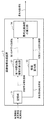
- FIG. 1 is a block diagram showing an image information processing system 100 according to the first embodiment of this invention.
- the image information processing system 100 according to this embodiment is roughly provided with an image information processing device 1, an image supply device 5, and an output device 6.
- the image information processing apparatus 1 is communicably connected to the image supply apparatus 5 and the output apparatus 6.
- the direction of the arrow in the block diagram of FIG. 1 and the like of the present application is an example, and the direction of the signal between the blocks is not limited.
- the image supply device 5 is, for example, a photographing device that observes the intensity of electromagnetic waves (observation light) reflected from an observation target for a plurality of different wavelength bands and outputs the observation results as an observation image.
- the image supply device 5 may be a storage device such as a hard disk or an information processing device such as a server device that stores an observation image that is a result observed by such a photographing device.
- N N is an integer of 2 or more
- N is the number of wavelength bands in which the image supply device 5 (imaging device) observes the observation target.
- the image supply apparatus 5 supplies N (sheets) observation images associated with the wavelength band to the image information processing apparatus 1.
- the image supply device 5 may supply the N observation images and the upper limit value and the lower limit value of the wavelength band associated with each observation image to the image information processing device 1.
- the image supply device 5 supplies information representing the observation environment when observed to the image information processing device 1.
- the information representing the observation environment includes, for example, the solar altitude at the time of observation, the observation date, the observation time, the latitude and longitude of the observation target region, the topography of the observation target region, the water vapor amount and the aerosol amount in the observation target region, and the like.
- the image supply device 5 observes the distribution of the intensity of observation light that reaches the image supply device 5 through the medium such as air or dust from the observation target.
- the observation light includes visible light, infrared light, and ultraviolet light.
- the image supply device 5 may observe the distribution of the intensity of electromagnetic waves not included in visible light, infrared light, and ultraviolet light.
- the observation light reaching the image supply device 5 includes a component reaching from the medium in addition to a component reaching due to reflection at the observation target.
- the observation target is, for example, the ground surface.
- the image supply device 5 is mounted on an airplane or an artificial satellite, for example, and observes reflected light reflected from the ground surface as a part of observation light for a plurality of different wavelength bands.
- the image supply device 5 is, for example, a camera that photographs through a band pass filter.
- the image supply device 5 may perform observation using N band-pass filters that selectively transmit observation light in any of N (seed) wavelength bands.
- the image supply apparatus 5 may observe the ground surface far away from the ground surface or near the ground surface instead of observing the ground surface from the sky.
- the width of the wavelength band may not be uniform.
- the image supply device 5 outputs the observation results as N observation images.
- the N observation images are images representing the distribution of brightness related to the observation target, observed in any of N different wavelength bands.
- the luminance value of each pixel represents the intensity of observation light that has arrived from the direction corresponding to the pixel.
- These N observation images are images obtained by observing the same observation target, for example.
- the N images are, for example, the result of the image supply device 5 observing the target for N wavelength bands.
- these N images may be images obtained by observing different observation targets. In that case, for example, an administrator who manages the image supply device 5 or the image information processing device 1 may select N images.
- the output device 6 is, for example, a display device.
- the output device 6 may be, for example, an object identification device that extracts information indicating the material and state of the photographed object from the observation image.
- the image information processing apparatus 1 includes a storage unit 11, a first intermediate optical path luminance calculation unit 12, an illuminance calculation unit 13, a final optical path luminance calculation unit 14, an optical path luminance correction unit 15, and an output unit 19.
- the storage unit 11 is a storage device such as a magnetic disk or an electronic memory.
- the first intermediate optical path luminance calculation unit 12, the illuminance calculation unit 13, the final optical path luminance calculation unit 14, the optical path luminance correction unit 15, and the output unit 19 may be an electronic circuit or a computer program and its computer. In some cases, it is realized by a processor that operates according to a program.
- the storage unit 11 reads N observation images associated with the observed wavelength band from the image supply device 5.
- the storage unit 11 stores the read N observation images in association with the wavelength band in which the images are observed.
- the wavelength band associated with the observation image may be a combination of an upper limit value and a lower limit value of wavelengths indicating the wavelength band, for example.
- the wavelength band associated with the observation image may be an identifier assigned to a combination of an upper limit value and a lower limit value of wavelengths indicating the wavelength band.
- the storage unit 11 stores information representing the observation environment in association with the observation image.
- the information representing the observation environment is, for example, information including the solar altitude at the time of observation, the date of observation, the observation time, the latitude and longitude of the observation target area, the topography of the observation target area, the amount of water vapor and aerosol at the time of observation, etc. It is.
- the first intermediate optical path luminance calculation unit 12 calculates the luminance value of a pixel whose luminance value satisfies the criterion from all the pixels constituting the observation image associated with the N wavelength bands stored in the storage unit 11. Take out. Then, the first intermediate optical path luminance calculation unit 12 sets the extracted N luminance values as the first intermediate optical path luminance for each wavelength band. For example, the first intermediate optical path luminance calculation unit 12 extracts the minimum luminance value as the luminance value satisfying the criterion. Further, for example, when the first intermediate optical path luminance calculation unit 12 arranges the luminance values of all the pixels in ascending order as the luminance value satisfying the standard, the rank is a number obtained by multiplying the total number of pixels by a certain ratio. The luminance value at which
- a pixel corresponding to the luminance value extracted by the first intermediate optical path luminance calculation unit 12 is referred to as a “dark pixel”. Further, the assumption that the surface reflectance of the dark area on the ground surface, which is measured as the luminance value of the dark pixel, can be regarded as 0 is referred to as “dark pixel assumption”.
- the i-th wavelength band (i is an integer from 1 to N) in the N wavelength bands associated with the observation image is represented as ⁇ i .
- the luminance values of the dark pixels extracted in the N wavelength bands ⁇ i associated with the observation image are set as first intermediate optical path luminances ⁇ D ( ⁇ i ), respectively.
- the illuminance calculation unit 13 calculates the irradiance due to sunlight in the N wavelength bands ⁇ i based on the information representing the observation environment stored in the storage unit 11.
- the irradiance due to sunlight in the N wavelength bands ⁇ i calculated by the illuminance calculation unit 13 is represented as I ( ⁇ i ).
- the illuminance calculation unit 13 calculates the irradiance I ( ⁇ i ) using a physical model representing the irradiance shown in Non-Patent Document 1.
- the illuminance calculation unit 13 simulates the direct sunlight and the atmospheric scattered light using the solar zenith angle calculated from the location and the time, and the parameter representing the state of the atmosphere.
- the illumination intensity calculation part 13 can calculate the spectral irradiance of sunlight at the time of fine weather for every wavelength, for example.
- the illuminance calculation unit 13 first sets default values of parameters that have little influence on the simulation result. And the illumination intensity calculation part 13 is the irradiance per unit wavelength of the sunlight at the time of fine weather using the solar zenith angle and the value showing the state of the atmosphere among the information representing the observation environment. Calculate a certain spectral irradiance. And the illumination intensity calculation part 13 adds together the spectral irradiance of sunlight at the time of fine weather about the wavelength from the lower limit included in wavelength band (gamma) i to an upper limit. Thereby, the illuminance calculation unit 13 calculates the irradiance I ( ⁇ i ) for each of the N wavelength bands ⁇ i .
- the illuminance calculation unit 13 may store standard irradiance due to sunlight in the N wavelength bands ⁇ i and use it instead of the irradiance I ( ⁇ i ).
- the illuminance calculation unit 13 adds, for example, the spectral irradiance of sunlight at a point incident on the earth from outside the atmosphere shown in Non-Patent Document 2 with respect to the wavelengths from the lower limit value to the upper limit value included in the wavelength band ⁇ i . Thereby, the illuminance calculation unit 13 may calculate and store the irradiance for each of the N wavelength bands ⁇ i .
- the final optical path luminance calculation unit 14 includes a cost calculation unit 141, a second intermediate optical path luminance calculation unit 142, and a cost minimization unit 143.
- the second intermediate optical path luminance calculation unit 142 uses the irradiance I ( ⁇ i ) calculated by the illuminance calculation unit 13 and the atmospheric information output by the cost minimization unit 143 to use the second intermediate optical path luminance. Is calculated.
- M parameters representing the atmospheric information calculated by the cost minimizing unit 143 are represented as X j (j is an integer from 1 to M, and is a subscript for distinguishing the parameters). Atmospheric information Xj represents information about particles contained in the atmosphere including molecules, aerosols, sand, soot and the like.
- the atmospheric information X j is, for example, an angstrom index, atmospheric turbidity, atmospheric transmittance, optical thickness of atmospheric molecules, optical thickness of aerosol, visibility, or a value calculated using these.
- the second intermediate optical path luminance in the N wavelength bands ⁇ i calculated by the second intermediate optical path luminance calculation unit 142 is expressed as ⁇ M ( ⁇ i ).
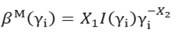
- Formulas shown in Formulas 2 to 4 are examples of formulas representing a calculation method for calculating the second intermediate optical path brightness ⁇ M ( ⁇ i ) in the wavelength band ⁇ i .
- the mathematical expressions shown in Equations 2 to 4 are empirical equations constructed based on empirical rules.
- the second intermediate optical path luminance calculation unit 142 calculates the second intermediate optical path luminance ⁇ M ( ⁇ i ) using any one of Equations 2 to 4.
- the unit (dimension) of ⁇ M ( ⁇ i ) in Equation 2 is W (watt) / steradian ⁇ (m (meter)) ⁇ 3 .
- the unit of I ( ⁇ i ) is W / m ⁇ 3 .
- the unit of ⁇ i is m.
- X 1 and X 2 in Equation 2 are empirically obtained parameters representing atmospheric information having the following meanings, and the portion excluding I ( ⁇ i ) on the right side in Equation 2 is dimensionless.
- X 1 a parameter representing the degree of atmospheric turbidity, such as the atmospheric turbidity coefficient
- X 2 A parameter representing the tendency of the particle size of the particles contained in the atmosphere, such as the angstrom index (large value when there are many small particles).
- Equation 3 The units of ⁇ M ( ⁇ i ), I ( ⁇ i ), and ⁇ i in Equation 3 are the same as those in Equation 2.
- X 1 to X 3 in Equation 3 are empirically obtained parameters representing atmospheric information having the following meanings, and the portion excluding I ( ⁇ i ) on the right side in Equation 3 is dimensionless. It has a dimension that satisfies X 1 and X 2 : As in Equation 1, X 3 : A parameter representing the ratio of scattered light (depending on the positional relationship between the sun and the sensor).
- Equation 4 The units of ⁇ M ( ⁇ i ), I ( ⁇ i ), and ⁇ i in Equation 4 are the same as those in Equation 2 and Equation 3.
- X 1 to X 4 in Equation 4 are empirically obtained parameters representing atmospheric information having the following meanings, and the portion excluding I ( ⁇ i ) on the right side in Equation 4 is dimensionless. It has a dimension that satisfies X 1 to X 3 : As in Equation 3 , X 4 : A parameter representing the degree of influence of atmospheric transmittance on the light path luminance.
- the cost calculation unit 141 includes the first intermediate optical path luminance ⁇ D ( ⁇ i ) output from the first intermediate optical path luminance calculation unit 12 and the second intermediate optical path calculated by the second intermediate optical path luminance calculation unit 142.
- the cost C is calculated using the brightness ⁇ M ( ⁇ i ).
- the cost C is a value indicating the degree of deviation between the second intermediate optical path luminance and the actual optical path luminance at the time of observation.
- Equation 5 is an example of an expression representing a method for calculating the cost C.
- the cost calculation unit 141 calculates the cost C using, for example, the mathematical formula shown in Equation 5.
- the cost minimizing unit 143 generates the atmospheric information X j by sequentially changing the values of the M parameters.
- the cost minimizing unit 143 outputs the final optical path luminance and the estimated atmospheric information when the value of the cost C calculated by the cost calculating unit 141 satisfies a predetermined condition.
- the final optical path luminance output by the cost minimizing unit 143 is the minimum value of the cost C calculated by the cost calculating unit 141 among the second intermediate optical path luminances calculated by the second intermediate optical path luminance calculating unit 142. It is a value.
- the estimated atmospheric information is atmospheric information when the cost calculated by the cost calculation unit 141 is minimized.
- the final optical path brightness is a calculated value of the final optical path brightness at the time of observation.
- the estimated atmospheric information is a final estimated value of atmospheric information at the time of observation.
- the final optical path luminance in the N wavelength bands ⁇ i calculated by the cost minimizing unit 143 is represented as ⁇ E ( ⁇ i ). Further, representative of the estimated atmospheric information and X E J. Further, the cost minimizing unit 143 uses, as an intermediate variable used in the process of calculating the final optical path brightness ⁇ E ( ⁇ i ), the minimum cost C m that is the current minimum cost, and the cost value is the minimum cost C.
- the atmospheric information X m j when m and the previous atmospheric information X b j when sequentially changing the values of the M parameters are stored.
- the cost minimizing unit 143 stores predetermined values as initial values of the minimum cost C m , the atmosphere information X m j at the time of the minimum cost, and the atmosphere information X j , respectively.
- the cost minimizing unit 143 outputs the atmospheric information X j by sequentially changing the values of the M parameters using the following method.
- the cost minimizing unit 143 first outputs the initial value of the stored atmospheric information Xj .
- the cost minimizing unit 143 performs the following processing and outputs the atmospheric information Xj .
- Cost minimization section 143 compares the cost C and the minimum cost C m. Cost minimization section 143, if the cost C is the minimum cost C m smaller than substitutes cost C to the minimum cost C m, substitutes atmospheric information X j to atmospheric information X m j at the minimum cost. The cost minimizing unit 143 stores the minimum cost C m whose value has been changed and the atmospheric information X m j at the time of the minimum cost. Cost minimization unit 143, the parameters of the atmospheric information X j, assigns the value obtained by adding a predetermined value to the parameter of atmospheric information X b j of previous outputs a value obtained. The cost minimizing unit 143 substitutes the value of the atmospheric information X j whose value has been changed into the previous atmospheric information X b j , and stores the obtained value.
- the cost minimizing unit 143 outputs the final optical path luminance ⁇ E ( ⁇ i ) and the estimated atmospheric information X E J when the value of the cost C satisfies a predetermined condition, for example, using the following method. .
- the cost minimizing unit 143 uses the mathematical formula used when the second intermediate optical path luminance calculating unit 142 calculates the second intermediate optical path luminance ⁇ M ( ⁇ i ) when the value of the cost C is smaller than a predetermined value. Use the same formula as. For example, when the second intermediate optical path luminance calculation unit 142 calculates the second intermediate optical path luminance ⁇ M ( ⁇ i ) using the formula shown in Equation 2, the cost minimizing unit 143 Works as expected.
- Cost minimization unit 143 the atmospheric information X j, substitutes the value of atmospheric information X b j last.
- the cost minimizing unit 143 calculates the second intermediate optical path luminance ⁇ M ( ⁇ i ) using the mathematical formula shown in Equation 2.
- the cost minimizing unit 143 substitutes the calculated value of the second intermediate optical path brightness ⁇ M ( ⁇ i ) for the final optical path brightness ⁇ E ( ⁇ i ).
- the cost minimizing unit 143 substitutes the value of the atmospheric information X m j at the minimum cost into the estimated atmospheric information X E J. Then, the cost minimizing unit 143 outputs the final optical path luminance ⁇ E ( ⁇ i ) and the estimated atmospheric information X E J.
- the second intermediate optical path luminance calculation unit 142 calculates the second intermediate optical path luminance ⁇ M ( ⁇ i ) using the mathematical formula shown in Equation 3 or Equation 4, the cost minimizing unit 143 is used. Also, the second intermediate optical path luminance ⁇ M ( ⁇ i ) is calculated using the mathematical formulas shown in Equation 3 or Equation 4.
- the cost minimizing unit 143 operates as follows when calculating the second intermediate optical path luminance ⁇ M ( ⁇ i ) using the mathematical formula shown in Equation 2, for example, and the air information X j Change the value sequentially and output. First, the cost minimizing unit 143 outputs an initial value of the atmospheric information Xj . Thereafter, each time the cost C is input, the cost minimizing unit 143 calculates and outputs the value of the atmospheric information X j using the mathematical formula (determinant) shown in Equation 6.
- Cost minimization section 143 substitutes the value of atmospheric information X j to atmospheric information X b j of previous substitutes the value of the cost C to the cost C b of the previous.
- the cost minimizing unit 143 stores the previous atmospheric information X b j and the previous cost C b whose values have been changed.
- the cost minimizing unit 143 operates as follows when the second intermediate optical path luminance ⁇ M ( ⁇ i ) is calculated using the mathematical expression shown in Equation 2, for example, so that the cost C is predetermined. It is determined that the condition is satisfied, and the final optical path luminance ⁇ E ( ⁇ i ) and the estimated atmospheric information X E J are output. Cost minimization section 143, the difference between the cost C b of the cost C before, is compared with a predetermined value. If the cost C and the difference between the cost C b previous is smaller than a predetermined value, cost minimization unit 143 operates as follows.
- Cost minimization unit 143 the atmospheric information X j, substitutes the value of atmospheric information X b j last.
- the cost minimizing unit 143 calculates the second intermediate optical path luminance ⁇ M ( ⁇ i ) using the mathematical formula shown in Equation 2.
- the cost minimizing unit 143 substitutes the calculated value of the second intermediate optical path brightness ⁇ M ( ⁇ i ) for the final optical path brightness ⁇ E ( ⁇ i ).
- the cost minimizing unit 143 substitutes the value of the atmospheric information X m j at the minimum cost into the estimated atmospheric information X E J. Then, the cost minimizing unit 143 outputs the final optical path luminance ⁇ E ( ⁇ i ) and the estimated atmospheric information X E J.
- the optical path luminance correction unit 15 uses the observation image stored in the storage unit 11 and the final optical path luminance ⁇ E ( ⁇ i ) output from the cost minimization unit 143 to calculate the optical path luminance component included in the observation image. By correcting, an optical path brightness correction image is generated.
- the optical path luminance correction unit 15 operates as follows.
- the optical path luminance correction unit 15 reads the observation image associated with the N wavelength bands ⁇ i from the storage unit 11.
- the optical path luminance correction unit 15 subtracts the final optical path luminance ⁇ E ( ⁇ i ) output from the cost minimizing unit 143 from the luminance value L ( ⁇ i ) for all the pixels constituting the read observation image.
- Make corrections That is, the corrected observation image is an image obtained by removing the optical path luminance component calculated by the final optical path luminance calculation unit 14 from the observation image stored in the storage unit 11. This image is used as an optical path brightness correction image.
- the optical path brightness correction unit 15 performs the above-described correction processing on all observation images stored in the storage unit 11 and associated with the N wavelength bands ⁇ i .
- the output unit 19 outputs the optical path luminance correction image generated by the optical path luminance correction unit 15 and the estimated atmospheric information X E J output from the cost minimizing unit 143 to the output device 6.
- the storage unit 11 reads, from the image supply device 5, N observation images associated with the N wavelength bands where the observation was performed and information representing the observation environment at the time of observation.
- the storage unit 11 stores the read observation image together with information representing the measurement environment in association with the wavelength band in which the observation image is observed (step S101).
- the first intermediate optical path luminance calculation unit 12 extracts the luminance value of the dark pixel whose luminance value satisfies the criterion from all the pixels for the observed image associated with each wavelength band, and extracts the luminance values for the N wavelength bands. The value is output as the first intermediate optical path luminance (step S102).
- the illuminance calculation unit 13 calculates the irradiance due to sunlight based on the information representing the measurement environment (step S103).
- the cost minimizing unit 143 sequentially updates and outputs the value of the atmospheric information every time the cost calculating unit 141 calculates a new cost (step S104).
- the second intermediate optical path luminance calculating unit 142 calculates the second intermediate optical path luminance based on the irradiance due to sunlight calculated by the illuminance calculating unit 13 and the atmospheric information output by the cost minimizing unit 143 (step S1). S105).
- the cost calculation unit 141 calculates a cost based on the first optical path luminance output from the first intermediate optical path luminance calculation unit 12 and the second intermediate optical path luminance calculated by the second intermediate optical path luminance calculation unit 142. (Step S106).
- Step S107 When the cost satisfies the predetermined condition (Yes in Step S107), the cost minimizing unit 143 calculates the final optical path luminance and the estimated atmospheric information (Step S108). If the cost does not satisfy the predetermined condition (No in step S107), the process returns to step S104.
- the optical path luminance correction unit 15 generates an optical path luminance correction image by removing the optical path luminance component included in the observation image using the observation image and the final optical path luminance (step S109).
- the output unit 19 outputs the optical path luminance correction image generated by the optical path luminance correction unit 15 to the output device 6 (step S110), and the entire process ends.
- the image information processing system 100 can calculate the optical path luminance with high accuracy even in a wavelength band in which the surface reflectance of a dark region cannot be regarded as 0 in an image representing an observed ground region.
- the reason is that the final optical path luminance calculation unit 14 performs the first intermediate optical path luminance calculation performed by the first intermediate optical path luminance calculation unit 12 and the second intermediate optical path luminance calculation unit 142.
- the intermediate optical path luminance is used to calculate a cost indicating the degree of divergence between the second intermediate optical path luminance and the actual optical path luminance, and the second intermediate optical path luminance at the time when the cost value becomes the minimum is calculated as the final optical path luminance. This is because the luminance is output.
- the optical path luminance is set for the wavelength band in which the surface reflectance of the region corresponding to the low luminance pixel in the ground region measured as an image cannot be regarded as zero. It cannot be calculated with high accuracy. That is, it is difficult to calculate the actual optical path luminance at the time of observation with high accuracy by assuming dark pixels.
- the first intermediate optical path luminance calculation unit 12 calculates the luminance value of the dark pixel whose luminance value satisfies the criterion for the observation image associated with the wavelength band. Take out and output as the first intermediate optical path luminance.
- the second intermediate optical path luminance calculation unit 142 repeats the second intermediate optical path luminance while changing the irradiance due to sunlight calculated by the illuminance calculation unit 13 and the atmospheric information calculated by the cost minimization unit 143. calculate.
- the final optical path luminance calculation unit 14 outputs, as the final optical path luminance, the second intermediate optical path luminance when the cost calculated from the first and second intermediate optical path luminances is minimum.
- the image information processing apparatus 1 according to the present embodiment calculates the optical path luminance with high accuracy even in a wavelength band in which the surface reflectance of the dark region cannot be regarded as 0 in the image representing the observed ground region. Can do.
- the final optical path luminance calculation unit 14 outputs estimated atmospheric information via the output unit 19 in addition to the final optical path luminance.
- the estimated atmospheric information is information indicating the state of the atmosphere at the time of observation. Therefore, the image information processing apparatus 1 according to the present embodiment can obtain atmospheric information that can be effectively used as weather information.
- FIG. 3 is a block diagram conceptually showing the structure of the image information processing system 200 according to the second embodiment.
- configurations that operate in the same manner as in the first embodiment are given the same numbers as in the first embodiment, and description thereof is omitted.
- the image information processing system 200 roughly includes an image information processing device 2, an image supply device 5, and an output device 6.
- the image information processing apparatus 2 includes a storage unit 11, a first intermediate optical path luminance calculation unit 12, an illuminance calculation unit 13, a final optical path luminance calculation unit 24, an optical path luminance correction unit 15, and an output unit 19.
- the final optical path luminance calculation unit 24 may be an electronic circuit or a computer program and a processor that operates according to the computer program.
- the final optical path luminance calculation unit 24 includes a wavelength selection unit 2411, a wavelength cost calculation unit 2412, a second intermediate optical path luminance calculation unit 142, and a cost minimization unit 143.
- the final optical path brightness calculation unit 24 includes a first intermediate optical path brightness ⁇ D ( ⁇ i ) (i is an integer from 1 to N) output from the first intermediate optical path brightness calculation unit 12, and an illuminance calculation unit.
- the final light path luminance ⁇ E ( ⁇ i ) and the estimated atmospheric information X E J are calculated using the irradiance I ( ⁇ i ) due to sunlight calculated by 13.
- the final optical path luminance calculation unit 24 selects a wavelength band from the N wavelength bands ⁇ i based on a predetermined standard, and calculates the selected wavelength band and the wavelength band that was not selected by different methods. The sum of the obtained values is taken as the cost.
- the final optical path brightness calculation unit 24 outputs the second intermediate optical path brightness when the cost satisfies a predetermined condition as the final optical path brightness.
- the final optical path luminance calculation unit 24 outputs the atmospheric information when the cost is minimized as the estimated atmospheric information X E J.
- the wavelength selection unit 2411 uses the first intermediate optical path luminance output from the first intermediate optical path luminance calculation unit 12 and the second intermediate optical path luminance calculated by the second intermediate optical path luminance calculation unit 142 to determine N One or more wavelength bands are selected from the observed wavelength bands, and the selected wavelength band is output.
- the number of wavelength bands selected by the wavelength selection unit 2411 is any number P from 1 to (N ⁇ 1).
- the wavelength band selected by the wavelength selection unit 2411 is represented as a selected wavelength band ⁇ j (j is an integer from s 1 to s P ).
- the wavelength selection unit 2411 sequentially compares the first intermediate optical path luminance ⁇ D ( ⁇ i ) and the second intermediate optical path luminance ⁇ M ( ⁇ i ) in N wavelength bands ⁇ i .
- the wavelength selection unit 2411 selects the wavelength band ⁇ i and selects the selected wavelength band ⁇ .
- the wavelength selection unit 2411 updates the value of j every time the selected wavelength band ⁇ j is stored, and sequentially stores from ⁇ s 1 to ⁇ s P.
- the wavelength cost calculation unit 2412 outputs the first intermediate optical path luminance ⁇ D ( ⁇ i ) output from the first intermediate optical path luminance calculation unit 12 and the second intermediate optical path calculated by the second intermediate optical path luminance calculation unit 142.
- the cost C is calculated using the luminance ⁇ M ( ⁇ i ) and the wavelength band ⁇ i selected by the wavelength selection unit 2411.
- the wavelength cost calculation unit 2412 stores predetermined values for the selected wavelength cost coefficient A and the non-selected wavelength cost coefficient B, respectively.
- the selected wavelength cost coefficient A is a coefficient representing the degree of influence of the first intermediate optical path luminance on the calculation of the final optical path luminance in the wavelength band where the dark pixel assumption is not satisfied.
- the non-selected wavelength cost coefficient B is a coefficient representing the degree of influence of the first intermediate optical path luminance on the calculation of the final optical path luminance in the wavelength band where the dark pixel assumption is satisfied.
- the default value of the selected wavelength cost coefficient A is set to a value smaller than the default value of the non-selected wavelength cost coefficient B. That is, the wavelength cost calculation unit 2412 calculates the cost C by assigning more weight to the wavelength band not selected by the wavelength selection unit 2411 than the wavelength band selected by the wavelength selection unit 2411.
- the wavelength cost calculation unit 2412 calculates a wavelength band excluding the selected wavelength band ⁇ j from among the N observed wavelength bands ⁇ i , as any of the non-selected wavelength bands ⁇ k (k is t 1 to t ( NP ) . Any integer).
- the wavelength cost calculation unit 2412 calculates the cost C using the mathematical formula shown in Equation 7. Note that “ ⁇ ” in the expression shown in Equation 7 is an operator indicating multiplication.
- the image information processing system 200 has an optical path luminance in a wavelength band where the surface reflectance of a dark region cannot be regarded as 0 in the image representing the observed ground region. It can be calculated with high accuracy.
- the final optical path luminance calculation unit 24 uses the first intermediate optical path luminance calculated by the first intermediate optical path luminance calculation unit 12 and the second intermediate optical path luminance calculation unit 142 calculated by the second intermediate optical path luminance calculation unit 142.
- the intermediate optical path luminance is used to calculate a cost indicating the degree of divergence between the second intermediate optical path luminance and the actual optical path luminance, and the second intermediate optical path luminance at the time when this cost is minimized is used as the final optical path luminance. It is because it outputs.
- the default value of the selected wavelength cost coefficient A stored in the wavelength cost calculation unit 2412 according to this embodiment is set to a value smaller than the default value of the non-selected wavelength cost coefficient B. Therefore, the image information processing apparatus 2 according to the present embodiment reduces the influence of the first intermediate optical path luminance estimation error that occurs in the wavelength band where the dark pixel assumption is not satisfied on the calculation of the final optical path luminance. Compared with the first embodiment, the optical path luminance can be calculated with higher accuracy.
- FIG. 4 is a block diagram conceptually showing the structure of the image information processing apparatus 3 according to the third embodiment.
- the image information processing apparatus 3 includes a storage unit 31, a first intermediate optical path luminance calculation unit 32, an illuminance calculation unit 33, and a final optical path luminance calculation unit 34.
- the storage unit 31 includes an observation image representing a result of observation of electromagnetic waves of different wavelength bands reflected on the ground surface, information representing the wavelength band, and information representing an observation environment when the electromagnetic waves are observed. Are stored in association with each other.
- the first intermediate optical path luminance calculation unit 32 sets, for each wavelength band, the luminance of a dark pixel whose luminance satisfies the standard among the pixels constituting the associated observation image as the first intermediate optical path luminance.
- the illuminance calculation unit 33 calculates the irradiance due to sunlight based on information representing the observation environment for each wavelength band.
- the final optical path brightness calculation unit 34 calculates the final optical path brightness for each wavelength band based on the irradiance and the first intermediate optical path brightness.
- the image information processing apparatus 3 can calculate the optical path luminance with high accuracy even in a wavelength band where the surface reflectance of a dark region cannot be regarded as 0 in an image representing an observed ground region.
- the reason is that the final optical path luminance calculation unit 34 uses the first intermediate optical path luminance calculated by the first intermediate optical path luminance calculation unit 32 and the irradiance due to sunlight calculated by the illuminance calculation unit 33. This is because the final optical path luminance close to the actual optical path luminance is calculated for each wavelength band.
- the units shown in FIGS. 1, 3, and 4 can be realized by a dedicated HW (HardWare) (electronic circuit). Further, at least the first intermediate optical path luminance calculation units 12 and 32, the illuminance calculation units 13 and 33, and the final optical path luminance calculation units 14, 24, and 34 are function (processing) units (software modules) of the software program. Can be considered. However, the division of each part shown in these drawings is a configuration for convenience of explanation, and various configurations can be assumed for mounting. An example of the hardware environment in this case will be described with reference to FIG.
- FIG. 7 is a diagram exemplarily illustrating a configuration of an information processing apparatus 900 (computer) that can execute the image information processing apparatus according to the exemplary embodiment of the present invention. That is, FIG. 7 shows the configuration of a computer (information processing apparatus) that can realize the image information processing apparatus shown in FIGS. 1, 3, and 4, and can realize each function in the above-described embodiment. Represents the hardware environment.
- the information processing apparatus 900 illustrated in FIG. 7 includes the following as constituent elements.
- CPU Central_Processing_Unit
- ROM Read_Only_Memory
- RAM Random_Access_Memory
- -Hard disk storage device
- a communication interface 905 with an external device ⁇ Bus 906 (communication line)
- a reader / writer 908 capable of reading and writing data stored in a recording medium 907 such as a CD-ROM (Compact_Disc_Read_Only_Memory) -I / O interface 909
- the information processing apparatus 900 is a general computer in which these configurations are connected via a bus 906.
- the present invention described by taking the above embodiment as an example supplies a computer program capable of realizing the following functions to the information processing apparatus 900 shown in FIG.
- the functions are the first intermediate optical path luminance calculation units 12 and 32, the illuminance calculation units 13 and 33, and the block configuration diagrams (FIGS. 1, 3, and 4) referred to in the description of the embodiment.
- This is the function of the final optical path luminance calculation units 14, 24 and 34, or the flowchart (FIG. 2).
- the present invention is then achieved by reading the computer program into the hardware CPU 901 for interpretation and execution.
- the computer program supplied to the apparatus may be stored in a readable / writable volatile memory (RAM 903) or a nonvolatile storage device such as the hard disk 904.
- a general procedure can be adopted as a method for supplying a computer program into the hardware.
- the procedure includes, for example, a method of installing in the apparatus via various recording media 907 such as a CD-ROM, and a method of downloading from the outside via a communication line such as the Internet.
- the present invention can be understood to be configured by a code constituting the computer program or a recording medium 907 in which the code is stored.
- the present invention can be used for farming support and resource exploration based on the result of measuring the ground surface from a high place.
Landscapes
- Physics & Mathematics (AREA)
- General Physics & Mathematics (AREA)
- Engineering & Computer Science (AREA)
- Theoretical Computer Science (AREA)
- Spectroscopy & Molecular Physics (AREA)
- Chemical & Material Sciences (AREA)
- Health & Medical Sciences (AREA)
- Life Sciences & Earth Sciences (AREA)
- Mathematical Physics (AREA)
- Analytical Chemistry (AREA)
- Biochemistry (AREA)
- General Health & Medical Sciences (AREA)
- Immunology (AREA)
- Pathology (AREA)
- Investigating Or Analysing Materials By Optical Means (AREA)
- Image Processing (AREA)
Abstract
Description

図1は、本発明の第一の実施の形態の画像情報処理システム100を示すブロック図である。本実施形態に係る画像情報処理システム100は、大別して、画像情報処理装置1、画像供給装置5、及び、出力装置6を備えている。画像情報処理装置1は、画像供給装置5及び出力装置6と通信可能に接続されている。尚、本願の図1等のブロック図における矢印の向きは一例であって、ブロック間の信号の向きを限定しない。
X1:大気混濁係数等の、大気の混濁度合を表すパラメタ、
X2:オングストローム指数等の、大気中に含まれる粒子の粒径の傾向(小さい粒子が多く存在していると大きい値)を表すパラメタ。

X1及びX2:数1と同様、
X3:散乱される光の割合を表すパラメタ(太陽とセンサとの位置関係に依存する)。

X1乃至X3:数3と同様、
X4:光路輝度における大気透過率の影響度合を表すパラメタ。


図3は、第2の実施形態に係る画像情報処理システム200の構成を概念的に示すブロック図である。以下の説明では、第1の実施形態と同様に動作する構成については、第1の実施形態と同じ番号を付与することにより、説明を省略する。

図4は、第3の実施形態に係る画像情報処理装置3の構成を概念的に示すブロック図である。
上述した各実施形態において図1、図3、及び、図4に示した各部は、専用のHW(HardWare)(電子回路)によって実現することができる。また、少なくとも、第1中間光路輝度の算出部12及び32、照度算出部13及び33、及び、最終光路輝度の算出部14、24及び34は、ソフトウェアプログラムの機能(処理)単位(ソフトウェアモジュール)と捉えることができる。但し、これらの図面に示した各部の区分けは、説明の便宜上の構成であり、実装に際しては、様々な構成が想定され得る。この場合のハードウェア環境の一例を、図7を参照して説明する。
・CPU(Central_Processing_Unit)901、
・ROM(Read_Only_Memory)902、
・RAM(Random_Access_Memory)903、
・ハードディスク(記憶装置)904、
・外部装置との通信インタフェース905、
・バス906(通信線)、
・CD-ROM(Compact_Disc_Read_Only_Memory)等の記録媒体907に格納されたデータを読み書き可能なリーダライタ908、
・入出力インタフェース909、
情報処理装置900は、これらの構成がバス906を介して接続された一般的なコンピュータである。
11 記憶部
12 第1中間光路輝度の算出部
13 照度算出部
14 最終光路輝度の算出部
141 コスト算出部
142 第2中間光路輝度の算出部
143 コスト最小化部
15 光路輝度の補正部
19 出力部
5 画像供給装置
6 出力装置
100 画像情報処理システム
2 画像情報処理装置
24 最終光路輝度の算出部
2411 波長選択部
2412 波長コスト算出部
200 画像情報処理システム
3 画像情報処理装置
31 記憶部
32 第1中間光路輝度の算出部
33 照度算出部
34 最終光路輝度の算出部
4 画像情報処理装置
41 画像読込部
42 暗画素特定部
43 センサパラメタ記憶部
44 大気伝搬補正部
900 情報処理装置
901 CPU
902 ROM
903 RAM
904 ハードディスク(記憶装置)
905 通信インタフェース
906 バス
907 記録媒体
908 リーダライタ
909 入出力インタフェース
Claims (10)
- 地表にて反射した異なる複数の波長帯域の電磁波が観測された結果を表す観測画像と、前記波長帯域を表す情報と、前記電磁波が観測された際の観測環境を表す情報とが、関連付けられて記憶された記憶手段と、
前記波長帯域ごとに、関連付けられた前記観測画像を構成する画素の中から、輝度が基準を満たす暗画素の輝度を第一の中間光路輝度とする第一中間光路輝度の算出手段と、
前記波長帯域ごとに、前記観測環境を表す情報に基づき、太陽光による放射照度を算出する照度算出手段と、
前記放射照度と、前記第一の中間光路輝度と、に基づき、前記波長帯域ごとに、最終光路輝度を算出する最終光路輝度の算出手段と、
を備える画像情報処理装置。 - 前記最終光路輝度の算出手段は、
大気の状態に関する大気情報を、前記大気情報を表す変数の値を変更することによって順次生成するコスト最小化手段と、
前記コスト最小化手段が前記大気情報を生成するたびに、前記大気情報、及び、前記放射照度に基づき、第二の中間光路輝度を算出する第二中間光路輝度の算出手段と、
前記第二の中間光路輝度と、前記電磁波を観測した際の実際の光路輝度との乖離度合を示すコストの値を、前記第一及び第二の中間光路輝度に基づき算出するコスト算出手段と、
を含み、
前記コスト最小化手段は、前記コストの値が所定の条件を満たすときの前記第二の中間光路輝度を、前記最終光路輝度として算出する、
請求項1に記載の画像情報処理装置。 - 前記最終光路輝度の算出手段は、
大気の状態に関する大気情報を、前記大気情報を表す変数の値を変更することによって順次生成するコスト最小化手段と、
前記コスト最小化手段が前記大気情報を生成するたびに、前記大気情報、及び、前記放射照度に基づき、第二の中間光路輝度を算出する第二中間光路輝度の算出手段と、
前記第一及び第二の中間光路輝度を基に、前記複数の波長帯域の中から、1以上の波長帯域選択する波長選択手段と、
前記第一及び第二の中間光路輝度、及び、前記波長選択手段が選択した波長帯域を示す情報を基に、前記第二の中間光路輝度と、前記電磁波を観測した際の実際の光路輝度との乖離度合を示すコストの値を算出する波長コスト算出手段と、
を含み、
前記コスト最小化手段は、前記コストの値が所定の条件を満たすときの前記第二の中間光路輝度を、前記最終光路輝度として算出する、
請求項1に記載の画像情報処理装置。 - 前記波長選択手段は、前記第一の中間光路輝度が前記第二の中間光路輝度よりも大きくなる前記波長帯域を選択し、
前記波長コスト算出手段は、前記波長選択手段が選択しなかった前記波長帯域について、前記波長選択手段が選択した前記波長帯域よりも重みを付けて、前記コストの値を算出する、
請求項3に記載の画像情報処理装置。 - 前記コスト最小化手段は、前記コストの値が最小となるときの前記第二の中間光路輝度を、前記最終光路輝度として算出する、
請求項2乃至4のいずれかに記載の画像情報処理装置。 - 前記コスト最小化手段は、前記コストの値が、前記所定の条件を満たすときの前記大気情報を外部に出力する、
請求項2乃至5のいずれかに記載の画像情報処理装置。 - 前記波長帯域ごとに、前記観測画像から前記最終光路輝度が示す成分を除去した光路輝度補正画像を生成する光路輝度の補正手段
をさらに備える請求項1乃至6のいずれかに記載の画像情報処理装置。 - 請求項1乃至7のいずれかに記載の画像情報処理装置と、
前記画像情報処理装置と通信可能に接続され、前記観測画像を、当該観測画像が観測された前記波長帯域、及び、前記測定環境を表す情報に関連付けて、前記画像情報処理装置に入力する画像供給装置と、
を備える、画像情報処理システム。 - 地表にて反射した異なる複数の波長帯域の電磁波が観測された結果を表す観測画像と、前記波長帯域を表す情報と、前記電磁波が観測された際の観測環境を表す情報と、を関連付けて記憶手段が記憶している場合に、
情報処理装置によって、
前記波長帯域ごとに、関連付けられた前記観測画像を構成する画素の中から、輝度が基準を満たす暗画素の輝度を第一の中間光路輝度とし、
前記波長帯域ごとに、前記観測環境を表す情報に基づき、太陽光による放射照度を算出し、
前記放射照度と、前記第一の中間光路輝度と、に基づき、前記波長帯域ごとに、最終光路輝度を算出する、
画像情報処理方法。 - 地表にて反射した異なる複数の波長帯域の電磁波が観測された結果を表す観測画像と、前記波長帯域を表す情報と、前記電磁波が観測された際の観測環境を表す情報と、が関連付けされて記憶された記憶手段にアクセス可能なコンピュータに、
前記波長帯域ごとに、関連付けられた前記観測画像を構成する画素の中から、輝度が基準を満たす暗画素の輝度を第一の中間光路輝度とする中間光路輝度の算出処理と、
前記波長帯域ごとに、前記観測環境を表す情報に基づき、太陽光による放射照度を算出する照度算出処理と、
前記放射照度と、前記第一の中間光路輝度と、に基づき、前記波長帯域ごとに、最終光路輝度を算出する最終光路輝度の算出処理と、
を実行させる画像情報処理プログラムが格納された記録媒体。
Priority Applications (3)
| Application Number | Priority Date | Filing Date | Title |
|---|---|---|---|
| US15/535,128 US10262225B2 (en) | 2014-12-19 | 2015-12-17 | Image information processing device, image information processing system, image information processing method, and recording medium storing image information processing program |
| EP15869562.7A EP3236237B1 (en) | 2014-12-19 | 2015-12-17 | Image information processing device, image information processing method, and recording medium storing image information processing program |
| JP2016564690A JP6772838B2 (ja) | 2014-12-19 | 2015-12-17 | 画像情報処理装置、画像情報処理システム、画像情報処理方法、及び、画像情報処理プログラム |
Applications Claiming Priority (2)
| Application Number | Priority Date | Filing Date | Title |
|---|---|---|---|
| JP2014257039 | 2014-12-19 | ||
| JP2014-257039 | 2014-12-19 |
Publications (1)
| Publication Number | Publication Date |
|---|---|
| WO2016098353A1 true WO2016098353A1 (ja) | 2016-06-23 |
Family
ID=56126261
Family Applications (1)
| Application Number | Title | Priority Date | Filing Date |
|---|---|---|---|
| PCT/JP2015/006280 Ceased WO2016098353A1 (ja) | 2014-12-19 | 2015-12-17 | 画像情報処理装置、画像情報処理システム、画像情報処理方法、及び、画像情報処理プログラムが格納された記録媒体 |
Country Status (4)
| Country | Link |
|---|---|
| US (1) | US10262225B2 (ja) |
| EP (1) | EP3236237B1 (ja) |
| JP (1) | JP6772838B2 (ja) |
| WO (1) | WO2016098353A1 (ja) |
Cited By (2)
| Publication number | Priority date | Publication date | Assignee | Title |
|---|---|---|---|---|
| WO2017169946A1 (ja) * | 2016-03-30 | 2017-10-05 | 日本電気株式会社 | 情報処理装置、情報処理システム、情報処理方法およびプログラム記憶媒体 |
| JP2021005206A (ja) * | 2019-06-26 | 2021-01-14 | キヤノン株式会社 | 画像処理装置、画像処理方法、およびプログラム |
Families Citing this family (3)
| Publication number | Priority date | Publication date | Assignee | Title |
|---|---|---|---|---|
| CN106327421A (zh) * | 2016-09-13 | 2017-01-11 | 首都师范大学 | 一种图像数据存储方法及装置 |
| AU2018202759A1 (en) * | 2017-10-31 | 2019-05-16 | Grand Performance Online Pty Limited | A system, method and computer program for optimising and allocating resources in a space for defined periods of time |
| WO2019121097A1 (en) * | 2017-12-21 | 2019-06-27 | Basf Se | Apparatus for determining agricultural relevant information |
Citations (3)
| Publication number | Priority date | Publication date | Assignee | Title |
|---|---|---|---|---|
| US20100008595A1 (en) * | 2008-07-08 | 2010-01-14 | Harris Corporation | Automated atmospheric characterization of remotely sensed multi-spectral imagery |
| JP2013225243A (ja) * | 2012-04-23 | 2013-10-31 | Mitsubishi Electric Corp | 画像処理装置及び画像処理方法 |
| JP2015036850A (ja) * | 2013-08-12 | 2015-02-23 | 日本電気株式会社 | 画像処理装置、画像処理方法および画像処理プログラム |
Family Cites Families (3)
| Publication number | Priority date | Publication date | Assignee | Title |
|---|---|---|---|---|
| US20060126959A1 (en) * | 2004-12-13 | 2006-06-15 | Digitalglobe, Inc. | Method and apparatus for enhancing a digital image |
| JP5834584B2 (ja) * | 2011-07-25 | 2015-12-24 | ソニー株式会社 | 情報処理装置、情報処理方法、プログラム及び蛍光スペクトルの強度補正方法 |
| US9396528B2 (en) | 2013-03-15 | 2016-07-19 | Digitalglobe, Inc. | Atmospheric compensation in satellite imagery |
-
2015
- 2015-12-17 EP EP15869562.7A patent/EP3236237B1/en active Active
- 2015-12-17 WO PCT/JP2015/006280 patent/WO2016098353A1/ja not_active Ceased
- 2015-12-17 US US15/535,128 patent/US10262225B2/en active Active
- 2015-12-17 JP JP2016564690A patent/JP6772838B2/ja active Active
Patent Citations (3)
| Publication number | Priority date | Publication date | Assignee | Title |
|---|---|---|---|---|
| US20100008595A1 (en) * | 2008-07-08 | 2010-01-14 | Harris Corporation | Automated atmospheric characterization of remotely sensed multi-spectral imagery |
| JP2013225243A (ja) * | 2012-04-23 | 2013-10-31 | Mitsubishi Electric Corp | 画像処理装置及び画像処理方法 |
| JP2015036850A (ja) * | 2013-08-12 | 2015-02-23 | 日本電気株式会社 | 画像処理装置、画像処理方法および画像処理プログラム |
Non-Patent Citations (1)
| Title |
|---|
| See also references of EP3236237A4 * |
Cited By (4)
| Publication number | Priority date | Publication date | Assignee | Title |
|---|---|---|---|---|
| WO2017169946A1 (ja) * | 2016-03-30 | 2017-10-05 | 日本電気株式会社 | 情報処理装置、情報処理システム、情報処理方法およびプログラム記憶媒体 |
| US10872397B2 (en) | 2016-03-30 | 2020-12-22 | Nec Corporation | Optical path radiance correction device |
| JP2021005206A (ja) * | 2019-06-26 | 2021-01-14 | キヤノン株式会社 | 画像処理装置、画像処理方法、およびプログラム |
| JP7263149B2 (ja) | 2019-06-26 | 2023-04-24 | キヤノン株式会社 | 画像処理装置、画像処理方法、およびプログラム |
Also Published As
| Publication number | Publication date |
|---|---|
| US10262225B2 (en) | 2019-04-16 |
| JP6772838B2 (ja) | 2020-10-21 |
| JPWO2016098353A1 (ja) | 2017-10-05 |
| EP3236237A4 (en) | 2018-08-08 |
| EP3236237B1 (en) | 2020-11-25 |
| US20170344845A1 (en) | 2017-11-30 |
| EP3236237A1 (en) | 2017-10-25 |
Similar Documents
| Publication | Publication Date | Title |
|---|---|---|
| Mosbrucker et al. | Camera system considerations for geomorphic applications of SfM photogrammetry | |
| Roth et al. | PhenoFly Planning Tool: flight planning for high-resolution optical remote sensing with unmanned areal systems | |
| JP6772838B2 (ja) | 画像情報処理装置、画像情報処理システム、画像情報処理方法、及び、画像情報処理プログラム | |
| Patience et al. | Spectroscopy across the brown dwarf/planetary mass boundary-I. Near-infrared JHK spectra | |
| Gauthier | Ultra-strong Mg II absorbers as a signature of cool intragroup gas | |
| JP2024521970A (ja) | 分光反射率測定方法およびシステム | |
| Fogarty et al. | The Relationship Between Brightest Cluster Galaxy Star Formation and the Intracluster Medium in CLASH | |
| Carlsten et al. | Wavelength-dependent PSFs and their impact on weak lensing measurements | |
| JP6201507B2 (ja) | 画像処理装置、画像処理方法および画像処理プログラム | |
| CN109643440A (zh) | 图像处理设备、图像处理方法和计算机可读记录介质 | |
| Yoo et al. | Intracluster light properties in a fossil cluster at z= 0.47 | |
| Sun et al. | Ten years of SNPP VIIRS reflective solar bands on-orbit calibration and performance | |
| JP2013033006A (ja) | 分光情報取得装置、分光情報取得方法及び分光情報取得用プログラム | |
| JP2018151832A (ja) | 情報処理装置、情報処理方法、および、プログラム | |
| Thiemann et al. | Center-to-limb variability of hot coronal EUV emissions during solar flares | |
| Chen et al. | Comparison of point spread models for underwater image restoration | |
| KR102345607B1 (ko) | 광학소자 설계 방법 및 그 장치 | |
| JP6856066B2 (ja) | 情報処理装置、情報処理システム、情報処理方法およびコンピュータプログラム | |
| Tuchin et al. | On random and systematic errors of a star tracker | |
| JP6747436B2 (ja) | 画像処理装置、画像処理システム、画像処理方法およびコンピュータプログラム | |
| Rupf | Wavelength Dependency of Atmospheric Extinction Coefficient at ETH Zürich HPP Telescope | |
| Jalan et al. | Constraining the ratio of median pixel optical depth profile around z∼ 4 quasars using the longitudinal proximity effect | |
| Wegner et al. | Image based performance analysis of thermal imagers | |
| JPWO2018021079A1 (ja) | 情報処理装置、情報処理方法、及び、プログラム | |
| Reulke et al. | Image quality of optical remote sensing data |
Legal Events
| Date | Code | Title | Description |
|---|---|---|---|
| 121 | Ep: the epo has been informed by wipo that ep was designated in this application |
Ref document number: 15869562 Country of ref document: EP Kind code of ref document: A1 |
|
| ENP | Entry into the national phase |
Ref document number: 2016564690 Country of ref document: JP Kind code of ref document: A |
|
| WWE | Wipo information: entry into national phase |
Ref document number: 15535128 Country of ref document: US |
|
| NENP | Non-entry into the national phase |
Ref country code: DE |
|
| REEP | Request for entry into the european phase |
Ref document number: 2015869562 Country of ref document: EP |