WO2016098819A1 - ディスクブレーキ装置 - Google Patents
ディスクブレーキ装置 Download PDFInfo
- Publication number
- WO2016098819A1 WO2016098819A1 PCT/JP2015/085250 JP2015085250W WO2016098819A1 WO 2016098819 A1 WO2016098819 A1 WO 2016098819A1 JP 2015085250 W JP2015085250 W JP 2015085250W WO 2016098819 A1 WO2016098819 A1 WO 2016098819A1
- Authority
- WO
- WIPO (PCT)
- Prior art keywords
- brake device
- disc brake
- piston
- caliper body
- force
- Prior art date
- Legal status (The legal status is an assumption and is not a legal conclusion. Google has not performed a legal analysis and makes no representation as to the accuracy of the status listed.)
- Ceased
Links
Images






Classifications
-
- F—MECHANICAL ENGINEERING; LIGHTING; HEATING; WEAPONS; BLASTING
- F16—ENGINEERING ELEMENTS AND UNITS; GENERAL MEASURES FOR PRODUCING AND MAINTAINING EFFECTIVE FUNCTIONING OF MACHINES OR INSTALLATIONS; THERMAL INSULATION IN GENERAL
- F16D—COUPLINGS FOR TRANSMITTING ROTATION; CLUTCHES; BRAKES
- F16D65/00—Parts or details
- F16D65/14—Actuating mechanisms for brakes; Means for initiating operation at a predetermined position
- F16D65/16—Actuating mechanisms for brakes; Means for initiating operation at a predetermined position arranged in or on the brake
- F16D65/18—Actuating mechanisms for brakes; Means for initiating operation at a predetermined position arranged in or on the brake adapted for drawing members together, e.g. for disc brakes
-
- B—PERFORMING OPERATIONS; TRANSPORTING
- B60—VEHICLES IN GENERAL
- B60T—VEHICLE BRAKE CONTROL SYSTEMS OR PARTS THEREOF; BRAKE CONTROL SYSTEMS OR PARTS THEREOF, IN GENERAL; ARRANGEMENT OF BRAKING ELEMENTS ON VEHICLES IN GENERAL; PORTABLE DEVICES FOR PREVENTING UNWANTED MOVEMENT OF VEHICLES; VEHICLE MODIFICATIONS TO FACILITATE COOLING OF BRAKES
- B60T13/00—Transmitting braking action from initiating means to ultimate brake actuator with power assistance or drive; Brake systems incorporating such transmitting means, e.g. air-pressure brake systems
- B60T13/10—Transmitting braking action from initiating means to ultimate brake actuator with power assistance or drive; Brake systems incorporating such transmitting means, e.g. air-pressure brake systems with fluid assistance, drive, or release
- B60T13/24—Transmitting braking action from initiating means to ultimate brake actuator with power assistance or drive; Brake systems incorporating such transmitting means, e.g. air-pressure brake systems with fluid assistance, drive, or release the fluid being gaseous
- B60T13/26—Compressed-air systems
- B60T13/38—Brakes applied by springs or weights and released by compressed air
-
- B—PERFORMING OPERATIONS; TRANSPORTING
- B60—VEHICLES IN GENERAL
- B60T—VEHICLE BRAKE CONTROL SYSTEMS OR PARTS THEREOF; BRAKE CONTROL SYSTEMS OR PARTS THEREOF, IN GENERAL; ARRANGEMENT OF BRAKING ELEMENTS ON VEHICLES IN GENERAL; PORTABLE DEVICES FOR PREVENTING UNWANTED MOVEMENT OF VEHICLES; VEHICLE MODIFICATIONS TO FACILITATE COOLING OF BRAKES
- B60T17/00—Component parts, details, or accessories of power brake systems not covered by groups B60T8/00, B60T13/00 or B60T15/00, or presenting other characteristic features
- B60T17/08—Brake cylinders other than ultimate actuators
-
- F—MECHANICAL ENGINEERING; LIGHTING; HEATING; WEAPONS; BLASTING
- F16—ENGINEERING ELEMENTS AND UNITS; GENERAL MEASURES FOR PRODUCING AND MAINTAINING EFFECTIVE FUNCTIONING OF MACHINES OR INSTALLATIONS; THERMAL INSULATION IN GENERAL
- F16D—COUPLINGS FOR TRANSMITTING ROTATION; CLUTCHES; BRAKES
- F16D55/00—Brakes with substantially-radial braking surfaces pressed together in axial direction, e.g. disc brakes
- F16D55/02—Brakes with substantially-radial braking surfaces pressed together in axial direction, e.g. disc brakes with axially-movable discs or pads pressed against axially-located rotating members
- F16D55/22—Brakes with substantially-radial braking surfaces pressed together in axial direction, e.g. disc brakes with axially-movable discs or pads pressed against axially-located rotating members by clamping an axially-located rotating disc between movable braking members, e.g. movable brake discs or brake pads
- F16D55/224—Brakes with substantially-radial braking surfaces pressed together in axial direction, e.g. disc brakes with axially-movable discs or pads pressed against axially-located rotating members by clamping an axially-located rotating disc between movable braking members, e.g. movable brake discs or brake pads with a common actuating member for the braking members
- F16D55/225—Brakes with substantially-radial braking surfaces pressed together in axial direction, e.g. disc brakes with axially-movable discs or pads pressed against axially-located rotating members by clamping an axially-located rotating disc between movable braking members, e.g. movable brake discs or brake pads with a common actuating member for the braking members the braking members being brake pads
- F16D55/226—Brakes with substantially-radial braking surfaces pressed together in axial direction, e.g. disc brakes with axially-movable discs or pads pressed against axially-located rotating members by clamping an axially-located rotating disc between movable braking members, e.g. movable brake discs or brake pads with a common actuating member for the braking members the braking members being brake pads in which the common actuating member is moved axially, e.g. floating caliper disc brakes
-
- F—MECHANICAL ENGINEERING; LIGHTING; HEATING; WEAPONS; BLASTING
- F16—ENGINEERING ELEMENTS AND UNITS; GENERAL MEASURES FOR PRODUCING AND MAINTAINING EFFECTIVE FUNCTIONING OF MACHINES OR INSTALLATIONS; THERMAL INSULATION IN GENERAL
- F16D—COUPLINGS FOR TRANSMITTING ROTATION; CLUTCHES; BRAKES
- F16D55/00—Brakes with substantially-radial braking surfaces pressed together in axial direction, e.g. disc brakes
- F16D55/02—Brakes with substantially-radial braking surfaces pressed together in axial direction, e.g. disc brakes with axially-movable discs or pads pressed against axially-located rotating members
- F16D55/22—Brakes with substantially-radial braking surfaces pressed together in axial direction, e.g. disc brakes with axially-movable discs or pads pressed against axially-located rotating members by clamping an axially-located rotating disc between movable braking members, e.g. movable brake discs or brake pads
- F16D55/224—Brakes with substantially-radial braking surfaces pressed together in axial direction, e.g. disc brakes with axially-movable discs or pads pressed against axially-located rotating members by clamping an axially-located rotating disc between movable braking members, e.g. movable brake discs or brake pads with a common actuating member for the braking members
- F16D55/225—Brakes with substantially-radial braking surfaces pressed together in axial direction, e.g. disc brakes with axially-movable discs or pads pressed against axially-located rotating members by clamping an axially-located rotating disc between movable braking members, e.g. movable brake discs or brake pads with a common actuating member for the braking members the braking members being brake pads
- F16D55/226—Brakes with substantially-radial braking surfaces pressed together in axial direction, e.g. disc brakes with axially-movable discs or pads pressed against axially-located rotating members by clamping an axially-located rotating disc between movable braking members, e.g. movable brake discs or brake pads with a common actuating member for the braking members the braking members being brake pads in which the common actuating member is moved axially, e.g. floating caliper disc brakes
- F16D55/2265—Brakes with substantially-radial braking surfaces pressed together in axial direction, e.g. disc brakes with axially-movable discs or pads pressed against axially-located rotating members by clamping an axially-located rotating disc between movable braking members, e.g. movable brake discs or brake pads with a common actuating member for the braking members the braking members being brake pads in which the common actuating member is moved axially, e.g. floating caliper disc brakes the axial movement being guided by one or more pins engaging bores in the brake support or the brake housing
-
- F—MECHANICAL ENGINEERING; LIGHTING; HEATING; WEAPONS; BLASTING
- F16—ENGINEERING ELEMENTS AND UNITS; GENERAL MEASURES FOR PRODUCING AND MAINTAINING EFFECTIVE FUNCTIONING OF MACHINES OR INSTALLATIONS; THERMAL INSULATION IN GENERAL
- F16D—COUPLINGS FOR TRANSMITTING ROTATION; CLUTCHES; BRAKES
- F16D55/00—Brakes with substantially-radial braking surfaces pressed together in axial direction, e.g. disc brakes
- F16D55/24—Brakes with substantially-radial braking surfaces pressed together in axial direction, e.g. disc brakes with a plurality of axially-movable discs, lamellae, or pads, pressed from one side towards an axially-located member
- F16D55/26—Brakes with substantially-radial braking surfaces pressed together in axial direction, e.g. disc brakes with a plurality of axially-movable discs, lamellae, or pads, pressed from one side towards an axially-located member without self-tightening action
- F16D55/36—Brakes with a plurality of rotating discs all lying side by side
- F16D55/40—Brakes with a plurality of rotating discs all lying side by side actuated by a fluid-pressure device arranged in or one the brake
-
- F—MECHANICAL ENGINEERING; LIGHTING; HEATING; WEAPONS; BLASTING
- F16—ENGINEERING ELEMENTS AND UNITS; GENERAL MEASURES FOR PRODUCING AND MAINTAINING EFFECTIVE FUNCTIONING OF MACHINES OR INSTALLATIONS; THERMAL INSULATION IN GENERAL
- F16D—COUPLINGS FOR TRANSMITTING ROTATION; CLUTCHES; BRAKES
- F16D59/00—Self-acting brakes, e.g. coming into operation at a predetermined speed
- F16D59/02—Self-acting brakes, e.g. coming into operation at a predetermined speed spring-loaded and adapted to be released by mechanical, fluid, or electromagnetic means
-
- F—MECHANICAL ENGINEERING; LIGHTING; HEATING; WEAPONS; BLASTING
- F16—ENGINEERING ELEMENTS AND UNITS; GENERAL MEASURES FOR PRODUCING AND MAINTAINING EFFECTIVE FUNCTIONING OF MACHINES OR INSTALLATIONS; THERMAL INSULATION IN GENERAL
- F16D—COUPLINGS FOR TRANSMITTING ROTATION; CLUTCHES; BRAKES
- F16D65/00—Parts or details
- F16D65/005—Components of axially engaging brakes not otherwise provided for
- F16D65/0068—Brake calipers
-
- F—MECHANICAL ENGINEERING; LIGHTING; HEATING; WEAPONS; BLASTING
- F16—ENGINEERING ELEMENTS AND UNITS; GENERAL MEASURES FOR PRODUCING AND MAINTAINING EFFECTIVE FUNCTIONING OF MACHINES OR INSTALLATIONS; THERMAL INSULATION IN GENERAL
- F16D—COUPLINGS FOR TRANSMITTING ROTATION; CLUTCHES; BRAKES
- F16D65/00—Parts or details
- F16D65/14—Actuating mechanisms for brakes; Means for initiating operation at a predetermined position
- F16D65/16—Actuating mechanisms for brakes; Means for initiating operation at a predetermined position arranged in or on the brake
- F16D65/18—Actuating mechanisms for brakes; Means for initiating operation at a predetermined position arranged in or on the brake adapted for drawing members together, e.g. for disc brakes
- F16D65/183—Actuating mechanisms for brakes; Means for initiating operation at a predetermined position arranged in or on the brake adapted for drawing members together, e.g. for disc brakes with force-transmitting members arranged side by side acting on a spot type force-applying member
-
- F—MECHANICAL ENGINEERING; LIGHTING; HEATING; WEAPONS; BLASTING
- F16—ENGINEERING ELEMENTS AND UNITS; GENERAL MEASURES FOR PRODUCING AND MAINTAINING EFFECTIVE FUNCTIONING OF MACHINES OR INSTALLATIONS; THERMAL INSULATION IN GENERAL
- F16D—COUPLINGS FOR TRANSMITTING ROTATION; CLUTCHES; BRAKES
- F16D65/00—Parts or details
- F16D65/38—Slack adjusters
- F16D65/40—Slack adjusters mechanical
- F16D65/42—Slack adjusters mechanical non-automatic
- F16D65/46—Slack adjusters mechanical non-automatic with screw-thread and nut
-
- F—MECHANICAL ENGINEERING; LIGHTING; HEATING; WEAPONS; BLASTING
- F16—ENGINEERING ELEMENTS AND UNITS; GENERAL MEASURES FOR PRODUCING AND MAINTAINING EFFECTIVE FUNCTIONING OF MACHINES OR INSTALLATIONS; THERMAL INSULATION IN GENERAL
- F16D—COUPLINGS FOR TRANSMITTING ROTATION; CLUTCHES; BRAKES
- F16D2121/00—Type of actuator operation force
- F16D2121/02—Fluid pressure
- F16D2121/08—Fluid pressure acting on a membrane-type actuator, e.g. for gas pressure
- F16D2121/10—Fluid pressure acting on a membrane-type actuator, e.g. for gas pressure for releasing a normally applied brake
-
- F—MECHANICAL ENGINEERING; LIGHTING; HEATING; WEAPONS; BLASTING
- F16—ENGINEERING ELEMENTS AND UNITS; GENERAL MEASURES FOR PRODUCING AND MAINTAINING EFFECTIVE FUNCTIONING OF MACHINES OR INSTALLATIONS; THERMAL INSULATION IN GENERAL
- F16D—COUPLINGS FOR TRANSMITTING ROTATION; CLUTCHES; BRAKES
- F16D2121/00—Type of actuator operation force
- F16D2121/14—Mechanical
-
- F—MECHANICAL ENGINEERING; LIGHTING; HEATING; WEAPONS; BLASTING
- F16—ENGINEERING ELEMENTS AND UNITS; GENERAL MEASURES FOR PRODUCING AND MAINTAINING EFFECTIVE FUNCTIONING OF MACHINES OR INSTALLATIONS; THERMAL INSULATION IN GENERAL
- F16D—COUPLINGS FOR TRANSMITTING ROTATION; CLUTCHES; BRAKES
- F16D2121/00—Type of actuator operation force
- F16D2121/18—Electric or magnetic
- F16D2121/20—Electric or magnetic using electromagnets
- F16D2121/22—Electric or magnetic using electromagnets for releasing a normally applied brake
-
- F—MECHANICAL ENGINEERING; LIGHTING; HEATING; WEAPONS; BLASTING
- F16—ENGINEERING ELEMENTS AND UNITS; GENERAL MEASURES FOR PRODUCING AND MAINTAINING EFFECTIVE FUNCTIONING OF MACHINES OR INSTALLATIONS; THERMAL INSULATION IN GENERAL
- F16D—COUPLINGS FOR TRANSMITTING ROTATION; CLUTCHES; BRAKES
- F16D2121/00—Type of actuator operation force
- F16D2121/18—Electric or magnetic
- F16D2121/24—Electric or magnetic using motors
- F16D2121/26—Electric or magnetic using motors for releasing a normally applied brake
-
- F—MECHANICAL ENGINEERING; LIGHTING; HEATING; WEAPONS; BLASTING
- F16—ENGINEERING ELEMENTS AND UNITS; GENERAL MEASURES FOR PRODUCING AND MAINTAINING EFFECTIVE FUNCTIONING OF MACHINES OR INSTALLATIONS; THERMAL INSULATION IN GENERAL
- F16D—COUPLINGS FOR TRANSMITTING ROTATION; CLUTCHES; BRAKES
- F16D2125/00—Components of actuators
- F16D2125/18—Mechanical mechanisms
- F16D2125/20—Mechanical mechanisms converting rotation to linear movement or vice versa
- F16D2125/22—Mechanical mechanisms converting rotation to linear movement or vice versa acting transversely to the axis of rotation
- F16D2125/28—Cams; Levers with cams
-
- F—MECHANICAL ENGINEERING; LIGHTING; HEATING; WEAPONS; BLASTING
- F16—ENGINEERING ELEMENTS AND UNITS; GENERAL MEASURES FOR PRODUCING AND MAINTAINING EFFECTIVE FUNCTIONING OF MACHINES OR INSTALLATIONS; THERMAL INSULATION IN GENERAL
- F16D—COUPLINGS FOR TRANSMITTING ROTATION; CLUTCHES; BRAKES
- F16D2125/00—Components of actuators
- F16D2125/18—Mechanical mechanisms
- F16D2125/20—Mechanical mechanisms converting rotation to linear movement or vice versa
- F16D2125/22—Mechanical mechanisms converting rotation to linear movement or vice versa acting transversely to the axis of rotation
- F16D2125/28—Cams; Levers with cams
- F16D2125/32—Cams; Levers with cams acting on one cam follower
-
- F—MECHANICAL ENGINEERING; LIGHTING; HEATING; WEAPONS; BLASTING
- F16—ENGINEERING ELEMENTS AND UNITS; GENERAL MEASURES FOR PRODUCING AND MAINTAINING EFFECTIVE FUNCTIONING OF MACHINES OR INSTALLATIONS; THERMAL INSULATION IN GENERAL
- F16D—COUPLINGS FOR TRANSMITTING ROTATION; CLUTCHES; BRAKES
- F16D2125/00—Components of actuators
- F16D2125/18—Mechanical mechanisms
- F16D2125/20—Mechanical mechanisms converting rotation to linear movement or vice versa
- F16D2125/34—Mechanical mechanisms converting rotation to linear movement or vice versa acting in the direction of the axis of rotation
- F16D2125/36—Helical cams, Ball-rotating ramps
-
- F—MECHANICAL ENGINEERING; LIGHTING; HEATING; WEAPONS; BLASTING
- F16—ENGINEERING ELEMENTS AND UNITS; GENERAL MEASURES FOR PRODUCING AND MAINTAINING EFFECTIVE FUNCTIONING OF MACHINES OR INSTALLATIONS; THERMAL INSULATION IN GENERAL
- F16D—COUPLINGS FOR TRANSMITTING ROTATION; CLUTCHES; BRAKES
- F16D2125/00—Components of actuators
- F16D2125/18—Mechanical mechanisms
- F16D2125/20—Mechanical mechanisms converting rotation to linear movement or vice versa
- F16D2125/34—Mechanical mechanisms converting rotation to linear movement or vice versa acting in the direction of the axis of rotation
- F16D2125/40—Screw-and-nut
-
- F—MECHANICAL ENGINEERING; LIGHTING; HEATING; WEAPONS; BLASTING
- F16—ENGINEERING ELEMENTS AND UNITS; GENERAL MEASURES FOR PRODUCING AND MAINTAINING EFFECTIVE FUNCTIONING OF MACHINES OR INSTALLATIONS; THERMAL INSULATION IN GENERAL
- F16D—COUPLINGS FOR TRANSMITTING ROTATION; CLUTCHES; BRAKES
- F16D2125/00—Components of actuators
- F16D2125/18—Mechanical mechanisms
- F16D2125/58—Mechanical mechanisms transmitting linear movement
- F16D2125/64—Levers
-
- F—MECHANICAL ENGINEERING; LIGHTING; HEATING; WEAPONS; BLASTING
- F16—ENGINEERING ELEMENTS AND UNITS; GENERAL MEASURES FOR PRODUCING AND MAINTAINING EFFECTIVE FUNCTIONING OF MACHINES OR INSTALLATIONS; THERMAL INSULATION IN GENERAL
- F16D—COUPLINGS FOR TRANSMITTING ROTATION; CLUTCHES; BRAKES
- F16D55/00—Brakes with substantially-radial braking surfaces pressed together in axial direction, e.g. disc brakes
- F16D55/02—Brakes with substantially-radial braking surfaces pressed together in axial direction, e.g. disc brakes with axially-movable discs or pads pressed against axially-located rotating members
- F16D55/22—Brakes with substantially-radial braking surfaces pressed together in axial direction, e.g. disc brakes with axially-movable discs or pads pressed against axially-located rotating members by clamping an axially-located rotating disc between movable braking members, e.g. movable brake discs or brake pads
Definitions
- the present invention relates to a disc brake device.
- a negative type disc brake device in which the load of a disc spring is directly used as a braking force uses a hydraulic force to release the braking force.
- a hydraulic force to release the braking force.
- it is desired to eliminate the space and piping for adopting the hydraulic mechanism and to simplify the size.
- an object of the present invention is to provide a disc brake device that is a negative type disc brake device that has a pressing force release mechanism other than hydraulic pressure and that can improve durability.
- a disc brake device having the following configuration.
- a disc brake device in which a piston disposed in a cylinder formed in a caliper body presses a brake pad by receiving a pressing force from an operating spring, and is provided in a part of the caliper body.
- a disc brake device comprising: a cam portion that widens a distance between the force receiver and releases the pressing force.
- the actuating spring is a disc spring arranged in a stack, and the caliper body has a through hole provided at the center of the disc spring.
- the disc brake device having the configuration as described in (2) above, there is no possibility that the disc springs arranged in layers are displaced, and the position of the piston or the like by the holding shaft can be adjusted.
- the disc brake device having the above-described configuration (1) or (2), wherein the cam portions are arranged so as to be paired symmetrically with respect to the piston as a base point. Is a disc brake device to which a rotational input portion connected to the cam portion that forms a pair across the piston is connected.
- the disc brake device having the configuration as described in the above (3), it is possible to apply the force when releasing the pressing force by the operating spring in a well-balanced manner. Furthermore, by providing a rotational power input unit, it is possible to input the rotational power to both cam portions that form a pair in one operation.
- the disc brake device having the configuration as described in (4) above, the disc brake device can be slimmed. Therefore, the free movement of the installation position of the disc brake device can be improved.
- the movable part is not exposed to the outside. Thus, there is no risk of malfunction due to dust adhesion or the like.
- the disc brake device having the configuration of (5), wherein the actuator is configured to apply an operating force in a direction to release the pressing force to the rotating power input unit via the connecting member. Is a disc brake device.
- piping around the actuator can be eliminated. Further, it is possible to eliminate a tank or a compressor that stores a fluid for operating the actuator.
- the disc brake device having the configuration of (7) above, wherein the motor gear unit includes a ball screw that rotates by operation of the motor gear unit and a ball nut that moves along the ball screw.
- a disc brake device that is attached and configured so that the connecting member is pushed out by the ball nut.
- the disc brake device having the configuration as described in the above (8) can release the pressing force of the operating spring even when the generated torque of the motor gear unit is small.
- the disc brake device having the configuration of (8) above, wherein the coupling member is provided with a magnetic body, and an electromagnet capable of attracting the magnetic body is provided at the pushing position of the coupling member. Disc brake device.
- the sliding range of the piston is set to an appropriate position. Can be adjusted.
- a disc brake device having any one of the constitutions (1) to (9) above, wherein a flat surface formed along a protruding direction of the reaction force receiver on a side portion of the piston And the support portion has a surface that contacts the flat surface.
- the support portion plays a role as a piston detent.
- the disc brake device having the above configuration is a negative type disc brake device, and it is possible to release the pressing force by the operating spring by the pressing force releasing mechanism other than the hydraulic pressure. Further, it is possible to improve the durability when the cam mechanism is adopted as compared with the conventional cam mechanism.
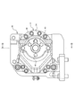
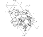
- FIG. 1 is a diagram showing a front configuration of a disc brake device according to a first embodiment of the present invention.
- FIG. 2 is a diagram showing the configuration of the right side surface of the disc brake device in FIG.
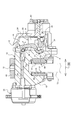
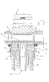
- FIG. 3 is a partial cross-sectional view taken along line AA in FIG. 4 is a partial cross-sectional view taken along the line BB in FIG.
- FIG. 5 is a partially enlarged view for explaining the cam mechanism.
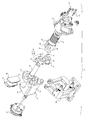
- FIG. 6 is an exploded perspective view showing the configuration of the disc brake device according to the first embodiment.
- FIG. 7 is a partial cross-sectional view showing a configuration of a disc brake device according to a second embodiment of the present invention.
- FIG. 8 is a partially exploded perspective view showing the configuration of the disc brake device according to the second embodiment.
- FIG. 1 is a diagram showing a front configuration of a disc brake device according to a first embodiment of the present invention.
- FIG. 2 is a diagram showing the configuration of the right side surface of the disc brake device in
- FIG. 9 is a perspective view showing a configuration of a disc brake device according to a third embodiment of the present invention.
- FIG. 10 is a cross-sectional view showing the configuration of the ABCD cross section in FIG.
- FIG. 11 is a cross-sectional view showing a state in which the brake is operating in the configuration of the EFGH cross section in FIG. 9.
- FIG. 12 is a cross-sectional view showing a state where the brake is released in the configuration of the EFGH cross section in FIG. 9.
- 13 is a cross-sectional view showing a state where only the ball nut and the nut holder are pulled back in the configuration of the EFGH cross section in FIG.
- the disc brake device 10 As shown in FIGS. 1 to 4, the disc brake device 10 according to the first exemplary embodiment of the present invention has a caliper body 12 and two brake pads (piston side pad 50, claw side pad 56) and The air chamber 62 is basically configured to be supported by a fixing unit (not shown) via a support 66.
- the caliper body 12 basically has a body main body 14, a claw portion 18, and a bridge portion 16.
- the body main body 14 is provided with a cylinder 20 and a support portion 22, and a case 24 is provided on a side surface opposite to the surface facing the rotor 70, thereby forming a bore 26 as an internal space.
- the cylinder 20 is provided with a sliding portion 30 of a piston 28, which will be described in detail later.
- the bore 26 is provided with an operating spring 36, a cam mechanism 42, and the like.
- the piston 28 includes a sliding part 30 and an interlocking part 32, and a reaction force receiver 34 projects from the outer periphery of the interlocking part 32.
- the reaction force receiver 34 is a portion to which a reaction force for releasing the pressing force by the operating spring 36 is applied, and is disposed at a position facing the support portion 22 provided in the body main body 14.
- the pressing force of the operating spring 36 can be released by pressing the reaction force receiver 34 with the support portion 22 as a base point.
- the flat surface 32a formed along the protrusion direction of the reaction force receiver 34 is provided in the side part of the interlocking
- An eccentric member 44b of a cam portion 44 which will be described later in detail, is brought into contact with the flat surface 32a, thereby serving as a rotation stopper for the piston 28.
- a through hole 30 a provided with a female screw is formed on the inner peripheral side of the sliding portion 30, and the screwed portion of the adjustment pin 38 is screwed into the female screw of the through hole 30 a. is doing.
- the adjustment pin 38 plays a role of adjusting the clearance when the piston side pad 50 and the claw side pad 56 that are brake pads are worn, and adjusting the piston 28 to be positioned in an appropriate operating range, and an operation described later. It also serves as a holding shaft for laminating and holding the disc spring as the spring 36.
- One end of the adjustment pin 38 abuts on the piston-side pad 50, and the other end is configured to protrude to the outside of the case 24.
- the adjustment pin 38 is disposed so as to penetrate both the sliding portion 30 and the interlocking portion 32 of the piston 28 in the axial direction of the piston 28. Therefore, both ends of the adjustment pin 38 are slidably supported in the axial direction (X) of the rotor 70 with respect to the caliper body 12 via the piston 28.
- the operating spring 36 is a pressing means for pressing the piston 28.
- a plurality of disc springs that are inserted through the other end of the adjustment pin 38 that is screwed into the piston 28 are stacked.
- the operating spring 36 is disposed between the sliding portion 30 of the piston 28 and the inner peripheral surface of the case 24 constituting the bore 26.
- the pressing force of the operating spring 36 is adjusted by an adjustment bolt 40 that is screwed into the end of the case 24 after the case 24 is fixed to the body main body 14.
- the adjustment bolt 40 has a tip projecting into the case 24 and tightening the bolt head presses the operating spring 36 to amplify the repulsive force (pad pressing force) of the operating spring 36.
- the cam mechanism 42 is an element responsible for pushing back the reaction force receiver 34 with the support portion 22 as a base point between the support portion 22 in the body main body 14 of the caliper body 12 and the reaction force receiver 34 in the interlocking portion 32 of the piston 28. It is. That is, the cam mechanism 42 is a pressing force release mechanism other than the hydraulic pressure that can release the pressing force by the operating spring 36.
- the cam mechanism 42 of the first embodiment is configured based on a cam portion 44 and a lever portion 46.
- the cam portion 44 is provided so as to correspond to each of the two reaction force receivers 34 provided as a pair via the piston 28.
- the cam portion 44 includes an eccentric member 44b serving as a rotation center and a cylindrical pin 44a disposed on the inner peripheral side of the eccentric member 44b.
- the pin 44a has a length that matches the width of the eccentric member 44b.
- the cam outer peripheral part of the eccentric member 44b is provided with the circular arc surface centering on the pin 44a as a sliding surface with the support part 22. As shown in FIG. And since the thickness of the eccentric member 44b differs along an arc surface, the distance from a pin center to an arc surface is changing continuously.
- the relationship r1 ⁇ r2 ⁇ r3 holds for r1 to r3 indicating the distance from the center point O shown in FIG.
- the distance between the two can be changed by moving the eccentric member 44b located between the support portion 22 and the reaction force receiver 34 so as to change the thickness thereof. That is, when a portion on the r1 side where the thickness of the eccentric member 44b is thin is disposed between the support portion 22 and the reaction force receiver 34, the piston-side pad 50, which will be described in detail later, is provided by the operating spring 36. The pressing force will work. On the other hand, when a portion on the r3 side where the eccentric member 44b is thick is disposed between the support portion 22 and the reaction force receiver 34, the pressing force by the operating spring 36 that has acted on the piston-side pad 50. Will be released.
- the cam portion 44 reduces the thickness of the portion located on the radially outer peripheral side of the rotor 70 and reduces the thickness of the portion located on the radially inner peripheral side of the rotor 70.
- the thickness is continuously varied so that the thickness is increased.
- the width d between the contact point P1 of the cam portion 44 with the support portion 22 and the contact point P2 with the reaction force receiver 34 is smaller than the diameter of the pin 44a. It is configured. This is to efficiently transmit force.
- a lever portion 46 that connects the two eccentric members 44b across the piston 28 is connected to a portion where the thickness of the eccentric member 44b is thin (portion located on the outer circumferential side of the rotor 70).
- the lever portion 46 serves as a rotational power input portion that rotates the eccentric member 44 b by being tilted in the axial direction (X) of the rotor 70.
- X axial direction
- the sliding member 48 is disposed between the support portion 22 and the eccentric member 44b, and between the eccentric member 44b and the pin 44a, thereby reducing resistance during sliding.
- the sliding member 48 may be a roller bearing, or may be a oilless bearing, and is not particularly limited.
- a piston-side pad 50 is disposed on the surface of the body main body 14 facing the rotor 70.
- the piston-side pad 50 is configured on the basis of a lining 52 that is a friction member and a pressure plate 54 made of a steel plate, and the adjustment pin 38 is in contact with the pressure plate 54.
- the claw portion 18 is disposed facing the body main body 14, receives a pressing force via the piston 28, and plays a role of sandwiching the rotor 70 between the piston side pad 50 and the claw side pad 56. For this reason, the nail
- FIG. The claw side pad 56 is configured based on a lining 58 and a pressure plate 60 in the same manner as the piston side pad 50 described above, and the pressure plate 60 is fastened to the claw portion 18.
- the lever portion 46 of the cam mechanism 42 is formed on the outer peripheral side of the claw portion 18 (that is, the side surface opposite to the side surface on which the rotor 70 is disposed).
- An air chamber 62 as an actuator for inputting power is disposed.
- the air chamber 62 can operate the cam mechanism 42 according to the expansion and contraction of the rod 64 by connecting the rod 64 to the lever portion 46 of the cam mechanism 42.
- the bridge portion 16 plays a role of connecting the body main body 14 and the claw portion 18 across the rotor 70.
- the bridge portion 16 in the first embodiment is provided with a through hole 16 a along the axial direction (X) of the rotor 70.
- the through hole 16 a communicates the outer periphery of the claw portion 18 and the bore 26 formed in the body main body 14, and the rod 64 in the air chamber 62 is inserted therethrough.
- the lining 58 of the claw-side pad 56 arranged on the surface of the claw portion 18 facing the rotor 70 is pressed against the sliding surface of the rotor 70.
- the rotor 70 is sandwiched between the piston-side pad 50 and the claw-side pad 56, and the state where the braking force is applied is maintained.
- the rod 64 protrudes toward the body main body 14 side.
- the lever portion 46 of the cam mechanism 42 tilts in the direction of arrow a (see FIG. 3).
- the eccentric member rotates in the direction of the arrow b (see FIG. 3) with the center point O of the pin 44a as a base point, and the reaction force receiver 34 changes to the arrow c (see FIG. 3) due to the change in thickness. ).
- the reaction force receiver 34 is pushed back, the piston 28 is slid in a direction to release the pressing force of the operating spring 36. Thereby, the pressing of the piston side pad 50 and the pressing of the claw side pad 56 which have been pressed by the adjustment pin 38 are released.
- the pressing force of the operating spring 36 can be released by the action of the cam mechanism 42 without using hydraulic pressure. Further, the cam mechanism 42 receives the pressing force of the operating spring 36 in the thickness direction of the eccentric member 44b. For this reason, the durability of the cam mechanism 42 can be improved as compared with the case where the pressing force is applied to the side surface of the rotating shaft as in the cam mechanism disclosed in the prior art.
- the arrangement form of the cam mechanism 42 is different from that of the first embodiment.
- the arc of the eccentric member 44b is disposed toward the body main body 14 and the pin 44a is in contact with the reaction force receiver 34.
- the arc of the eccentric member 44b is arranged toward the reaction force receiver 34, and the pin 44a is in contact with the support portion 22. .
- the cam mechanism 42 has such an arrangement, the action of the cam portion 44 when the lever portion 46 is tilted is reversed. Therefore, in the cam portion 44 of the second embodiment, the thickness of the portion located on the radially outer peripheral side of the rotor 70 is increased, and the thickness of the portion positioned on the radially inner peripheral side of the rotor 70 is decreased. It is configured as follows. And the lever part 46 is connected to the site
- the form of the contact surface in the support portion 22 and the reaction force receiver 34 is also different. This is to stabilize the arrangement state of the eccentric member 44b and the pin 44a.
- the support portion 22 is configured to be separate from the body main body 14. And the support part 22 arrange
- the disc brake device 10A according to the second embodiment obtains the same effect as the disc brake device 10 according to the first embodiment. be able to.
- the other constituent actions and effects of the disc brake device 10A according to the second embodiment are the same as those of the disc brake device 10 according to the first embodiment described above.
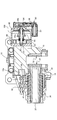
- FIG. 9 is a perspective view showing the configuration of the disc brake device according to the third embodiment
- FIG. 10 is a diagram showing the configuration of the ABCD cross section in FIG. 11 to 13 are diagrams showing the configuration of the EFGH cross section in FIG.
- the configuration of the actuator is different from the disc brake devices 10 and 10A according to the first and second embodiments described above.
- the actuator is the motor gear unit 80, and the ball screw unit 90 is attached to the motor gear unit 80, whereby the cam mechanism 42 is configured.
- the rod 64 which is a connecting member with the lever portion 46 is pushed and pulled.
- the motor gear unit 80 includes a motor 82 and a gear unit 84 for transmitting the rotational force of the motor 82 to a ball screw 92 described later.
- the gear unit 84 is composed of a plurality of gears arranged in the casing 86, and generates torque for rotating the ball screw 92 by changing the gear ratio.
- the ball screw unit 90 is configured based on a ball screw 92, a ball nut 94, an electromagnet 96, an electromagnet plate 98, and a casing 100.
- the ball screw 92 is a rotating shaft to which the rotational force of the motor 82 is transmitted from the motor gear unit 80 described above.
- the ball nut 94 is a slider that moves on the ball screw 92 along the axial direction of the ball screw 92 when the ball screw 92 rotates.
- a nut holder 94a is attached to the ball nut 94 according to the third embodiment.
- the nut holder 94a moves along with the operation of the ball nut 94 and plays a role of pressing the electromagnet plate 98 and receiving a pressing force of a preset spring 94b disposed between the casing 100 and the nut holder 94a.
- the preset spring 94b pushes back the nut holder 94a by turning off the power supply to the motor 82, and sets the ball nut 94 to the initial position. Play the role of regressing.
- the electromagnet 96 is provided on the side of the ball screw unit 90 where the caliper body 12 is disposed, and plays a role of attracting the electromagnet plate 98.
- the electromagnet plate 98 may be a flat plate made of a magnetic material that is attracted by the operation of the electromagnet 96.
- the electromagnet plate 98 is a plate to which the rod 64 is fastened, and the rod 64 is pushed out or pulled back when the electromagnet plate 98 moves in the axial direction of the ball screw 92.
- a guide stud 100 a is disposed between the electromagnet 96 and the casing 100 so as to penetrate the nut holder 94 a and the electromagnet plate 98.
- positioning the preset spring 94b mentioned above between the nut holder 94a and the casing 100 it is good to arrange
- the casing 100 is an outer shell that accommodates the above-described ball screw 92, ball nut 94, nut holder 94a, electromagnet 96, electromagnet plate 98, preset spring 94b, and guide stud 100a.
- the pressure is applied (that is, the brake is operating).
- the motor 82 is driven and the motor gear unit 80 is operated, the ball screw 92 in the ball screw unit 90 rotates in the forward rotation direction (for example, clockwise rotation).
- the ball nut 94 moves in the arrangement direction of the electromagnet 96 along the axial direction of the ball screw 92.
- the nut holder 94 a attached to the ball nut 94 presses the electromagnet plate 98.
- the rod 64 is pushed out, the cam mechanism 42 is operated, the release of the pressing force of the operating spring 36 is released, and the brake is released.
- the ball nut 94 is moved to the holding brake force acting position (initial position) determined by the load of the preset spring 94b and the spring 101 when the motor power supply is cut off.
- the motor 82 After the electromagnet plate 98 is attracted to the electromagnet 96, the motor 82 is supplied with electric power in reverse phase. As a result, the motor 82 is driven in reverse rotation, and the ball screw 92 that is rotated via the gear unit 84 is also rotated in the reverse rotation direction (for example, counterclockwise rotation). Due to the reverse rotation of the ball screw 92, the ball nut 94 moves together with the nut holder 94a in a direction away from the electromagnet 96. After the ball nut 94 is moved, the supply of electric power to the motor 82 is interrupted, whereby the ball nut 94 is pushed back to the initial position via the nut holder 94a that receives the force of the preset spring 94b.
- the piston (28) disposed in the cylinder (20) formed in the caliper body (12) receives a pressing force from the operating spring (36), so that the brake pad (the piston side pad 50 and the claw side) is received.
- the actuating spring (36) is a disc spring arranged in a stacked manner, and the through hole provided in the center of the disc spring has an axial direction of the rotor (70) with respect to the caliper body (12).
- the disc brake device (10, 10A, 10B) according to the above [1], wherein holding shafts (adjust pins 38) supported at both ends so as to be slidable in (X) are arranged. [3]
- the cam portions (44) are arranged so as to be paired symmetrically with respect to the piston (28).
- an actuator that inputs operating force to the rotational power input section (lever section 46).
- the disc brake device (10, 10A, 10B) according to the above [3], in which a motor gear unit 80) is provided.
- the turning input portion (lever portion 46) and the actuator (air chamber 62 or motor gear unit 80) of the cam portion (44) are provided in a hole portion (through hole) provided in the caliper body (12).
- the actuator is a motor gear unit (80) that applies an operating force in a direction to release the pressing force to the rotational power input portion (lever portion 46) via the connecting member (rod 64).
- the motor gear unit (80) is accompanied by a ball screw (ball screw 92) that rotates by the operation of the motor gear unit (80) and a ball nut (94) that moves along the ball screw.
- the connecting member (rod 64) includes a magnetic body (electromagnet plate 98).
- the disc brake device (10B) according to the above [8], wherein an electromagnet (96) capable of attracting the magnetic body is provided at the pushing position of the connecting member.
- the holding shaft (adjustment pin 38) has a threaded part between the piston (28), and one of the two end parts slides on the caliper body (12) via the piston. Any one of the above [2] to [9], in which the clearance between the brake pad (piston side pad 50 and claw side pad 56) can be adjusted via the threaded portion.
- a flat surface (32a) formed along the protruding direction of the reaction force receiver (34) is provided on the side of the piston (28),
- the disc brake device (10A) according to any one of [1] to [10], wherein the support portion (22) has a surface that comes into contact with the flat surface.
- the disc brake device of the present invention is not limited to the above-described embodiment, and can be appropriately modified and improved.
- the material, shape, dimensions, number, arrangement location, and the like of each component in the above-described embodiment are arbitrary and are not limited as long as the present invention can be achieved.
- the present application includes a Japanese patent application filed on December 16, 2014 (Japanese Patent Application No. 2014-253711), a Japanese patent application filed on March 2, 2015 (Japanese Patent Application No. 2015-40026), and November 30, 2015. This is based on the Japanese patent application (Japanese Patent Application No. 2015-234064), the contents of which are incorporated herein by reference.
- the disc brake device of the present invention it is possible to provide a negative type disc brake device that includes a pressing force release mechanism other than hydraulic pressure and that can also improve durability.
Landscapes
- Engineering & Computer Science (AREA)
- General Engineering & Computer Science (AREA)
- Mechanical Engineering (AREA)
- Transportation (AREA)
- Physics & Mathematics (AREA)
- Electromagnetism (AREA)
- Braking Arrangements (AREA)
Abstract
キャリパボディ(12)に形成されたシリンダ(20)内に配置されたピストン(28)が、作動ばね(36)からの押圧力を受けることによりピストン側パッド(50)を押圧するディスクブレーキ装置(10)であって、キャリパボディ(12)の一部に設けられた支持部(22)と、ピストン(28)の側部に突出し、支持部(22)に対向する反力受け(34)と、支持部(22)と反力受け(34)との間に設けられ、回動力の入力により、支持部(22)と反力受け(34)との間の距離を広げて前記押圧力を解除するカム部(44)と、を備える。
Description
本発明は、ディスクブレーキ装置に関する。
産業機械などで、回転体の保持にディスクブレーキ装置が用いられる際、皿ばねの荷重が直接制動力に用いられるネガティブタイプのディスクブレーキ装置では、制動力の解除に油圧の力を利用するものが一般的に知られている。ところが、ネガティブタイプのディスクブレーキ装置全体のシステムとしては、油圧機構を採用するためのスペースや配管を排除し、小型簡易化を図ることが望まれている。
ここで、ネガティブタイプのディスクブレーキ装置において、油圧以外の手段により、ピストンに力を作用させる方法としては、特許文献2や、特許文献3に開示されているような、カムを用いた技術が知られている。特許文献2に開示されているディスクブレーキ装置では、ピストンの側面に設けられた貫通孔に偏芯カムシャフトが配置され、偏心カムシャフトが回動されることで、ピストンに押圧力が与えられる構成が採られている。また、特許文献3に開示されているディスクブレーキ装置では、ピストンの後端にカムレバーが配置され、このカムレバーが回動されることにより、ピストンが押し出され、押圧力が与えられる構成が採られている。
ネガティブタイプのディスクブレーキ装置における制動力の解除機構として、カム機構を採用することは、非常に有効な手段であると考えられる。しかし、特許文献2に開示されている技術のように、ピストンの軸方向と交差するように設けられた貫通孔に偏芯カムシャフトが配置される構成がネガティブタイプのディスクブレーキ装置に採用された場合、偏心カムシャフトには、ブレーキ解放時、シャフトを曲げる方向のばね力が加えられる状態となる。このため、安全性を確保するためには、偏芯カムシャフトの強度を必要以上に高める(すなわち、太くする)必要が生ずるといった問題がある。
また、特許文献3に開示されている技術のように、ピストンの後端にカムレバーが配置される構成とされた場合、カムレバーは、ピストンの先端面を押圧することで、ピストンを押し戻す構成を採ることとなる。しかし、ピストンの先端面には、ブレーキパッドが配置されるため、実施的に特許文献3に開示されている構成を採用することはできない
そこで本発明では、上記問題を解決し、ネガティブタイプのディスクブレーキ装置であって、油圧以外の押圧力解除機構を備え、かつ耐久性の向上も図ることのできるディスクブレーキ装置を提供することを目的とする。
本発明の上記目的は、下記構成のディスクブレーキ装置により達成される。
(1) キャリパボディに形成されたシリンダ内に配置されたピストンが、作動ばねからの押圧力を受けることによりブレーキパッドを押圧するディスクブレーキ装置であって、前記キャリパボディの一部に設けられた支持部と、前記ピストンの側部に突出し、前記支持部に対向する反力受けと、前記支持部と前記反力受けとの間に設けられ、回動力の入力により、前記支持部と前記反力受けとの間の距離を広げて前記押圧力を解除するカム部と、を備えたディスクブレーキ装置。
(1) キャリパボディに形成されたシリンダ内に配置されたピストンが、作動ばねからの押圧力を受けることによりブレーキパッドを押圧するディスクブレーキ装置であって、前記キャリパボディの一部に設けられた支持部と、前記ピストンの側部に突出し、前記支持部に対向する反力受けと、前記支持部と前記反力受けとの間に設けられ、回動力の入力により、前記支持部と前記反力受けとの間の距離を広げて前記押圧力を解除するカム部と、を備えたディスクブレーキ装置。
(2) 上記(1)の構成を有するディスクブレーキ装置であって、前記作動ばねは、積層配置された皿ばねとされ、前記皿ばねの中心に設けられた貫通孔には、前記キャリパボディに対してロータの軸方向に摺動自在となるように両端部を支持された保持軸が配置されているディスクブレーキ装置。
上記(2)のような構成を有するディスクブレーキ装置によれば、積層配置された皿ばねにずれが生ずる虞が無く、保持軸によるピストン等の位置調整が可能となる。
(3) 上記(1)または(2)の構成を有するディスクブレーキ装置であって、前記カム部は、前記ピストンを基点として線対称に対を成すように配置され、対を成す前記カム部には、前記ピストンを跨いで対を成す前記カム部に接続される回動力入力部が接続されているディスクブレーキ装置。
上記(3)のような構成を有するディスクブレーキ装置によれば、作動ばねによる押圧力を解除する際の力をバランス良く付与することができる。さらに、回動力入力部を備えることにより、1つの動作で対を成すカム部双方に回動力を入力することができる。
(4) 上記(3)の構成を有するディスクブレーキ装置であって、前記キャリパボディにおける前記作動ばねの配置位置と反対側に位置する側面には、前記回動力入力部に作動力を入力するアクチュエータが備えられるディスクブレーキ装置。
上記(4)のような構成を有するディスクブレーキ装置によれば、ディスクブレーキ装置のスリム化を図ることができる。よって、ディスクブレーキ装置の設置位置の自由動を向上させることができる。
(5) 上記(4)の構成を有するディスクブレーキ装置であって、前記カム部の前記回動力入力部と前記アクチュエータは、前記キャリパボディに設けられた孔部を挿通する連結部材によって連結されているディスクブレーキ装置。
上記(5)のような構成を有するディスクブレーキ装置によれば、可動部を外部に晒すことが無くなる。よって、塵埃の付着等により動作不良を生じさせる虞が無い。
(6) 上記(5)の構成を有するディスクブレーキ装置であって前記アクチュエータは、前記連結部材をエアの力で作動させるエアチャンバであるディスクブレーキ装置。
上記(6)のような構成を有するディスクブレーキ装置によれば、カム部の回動力入力部を稼働させるアクチュエータの構成を簡単化することができる。また、エアチャンバの動作により連結部材を作動させるため、応答性が良い。
上記(6)のような構成を有するディスクブレーキ装置によれば、カム部の回動力入力部を稼働させるアクチュエータの構成を簡単化することができる。また、エアチャンバの動作により連結部材を作動させるため、応答性が良い。
(7) 上記(5)の構成を有するディスクブレーキ装置であって、前記アクチュエータは、前記連結部材を介して、前記回動力入力部に前記押圧力を解除する方向の作動力を与えるモータギアユニットであるディスクブレーキ装置。
上記(7)のような構成を有するディスクブレーキ装置によれば、アクチュエータ周りの配管を無くすことができる。また、アクチュエータを作動させるための流体を貯留するタンクやコンプレッサを排除することができる。
(8) 上記(7)の構成を有するディスクブレーキ装置であって、前記モータギアユニットには、当該モータギアユニットの稼働により回動するボールねじと、前記ボールねじに沿って移動するボールナットが付帯され、前記ボールナットによって前記連結部材が押し出される構成としたディスクブレーキ装置。
上記(8)のような構成を有するディスクブレーキ装置により、モータギアユニットの発生トルクが小さい場合であっても、作動ばねの押圧力を解除することが可能となる。
(9) 上記(8)の構成を有するディスクブレーキ装置であって、前記連結部材には、磁性体が備えられ、前記連結部材の押し出し位置には、前記磁性体を吸着可能な電磁石が備えられているディスクブレーキ装置。
上記(9)のような構成を有するディスクブレーキ装置により、モータに対する電力の供給が遮断された場合であっても、作動ばねの押圧力が解除された状態を維持することができる。
(10) 上記(2)の構成、または上記(2)の構成を有する上記(3)~上記(9)のいずれか1つの構成を有するディスクブレーキ装置であって、前記保持軸は前記ピストンとの間に螺合部を有し、前記両端部のうちの一方は、前記ピストンを介して前記キャリパボディに摺動すると共に、前記螺合部を介して前記ブレーキパッドとの隙間を調整可能な構成としたディスクブレーキ装置。
上記(10)のような構成を有するディスクブレーキ装置によれば、ブレーキパッドが摩耗し、ロータとパッドとの隙間が大きくなった場合であっても、ピストンの摺動範囲が適正位置となるように、調整することができる。
(11) 上記(1)~上記(9)のいずれか1つの構成を有するディスクブレーキ装置であって、前記ピストンの側部には、前記反力受けの突出方向に沿って形成された平坦面が設けられ、前記支持部は、前記平坦面に当接する面を有するディスクブレーキ装置。
上記(11)のような構成を有するディスクブレーキ装置によれば、支持部がピストンの回り止めとしての役割を担うこととなる。
上記構成を有するディスクブレーキ装置によれば、ネガティブタイプのディスクブレーキ装置であって、油圧以外の押圧力解除機構により、作動ばねによる押圧力を解除することが可能となる。また、従来のカム機構に比べ、カム機構を採用した際の耐久性の向上も図ることができる。
以下、本発明のディスクブレーキ装置に係る実施の形態について、図面を参照して詳細に説明する。
本発明の第1の実施形態に係るディスクブレーキ装置10は、図1~図4に示すように、外観上、キャリパボディ12と2つのブレーキパッド(ピストン側パッド50、爪側パッド56)、およびエアチャンバ62を有することを基本として構成され、サポート66を介して図示しない固定部に支持される。
キャリパボディ12は、ボディ本体14と、爪部18、およびブリッジ部16を有することを基本としている。ボディ本体14には、シリンダ20と支持部22が設けられ、ロータ70との対向面と反対側に位置する側面にケース24が備えられることで、内部空間としてのボア26が構成される。図4に示すように、シリンダ20には、詳細を後述するピストン28の摺動部30が配置される。また、ボア26には、作動ばね36やカム機構42などが配置される。
本第1の実施形態に係るピストン28は、摺動部30と連動部32とから構成され、連動部32の外周には、反力受け34が突設されている。反力受け34は、作動ばね36による押圧力を解除するための反力が加えられる部位であり、ボディ本体14に設けられた支持部22に対向する位置に配置される。このような配置構成とした場合、支持部22を基点として反力受け34が押圧されることで、作動ばね36による押圧力を解除することが可能となる。また、連動部32の側部には、反力受け34の突出方向に沿って形成された平坦面32aが設けられている(図6参照)。この平坦面32aに、支持部22に支えられた詳細を後述するカム部44の偏心部材44bが当接することで、ピストン28の回り止めとしての役割を担うこととなる。
摺動部30の内周側には、図4に示すように、雌ねじを設けた貫通孔30aが形成されており、この貫通孔30aの雌ねじには、アジャストピン38の螺合部が螺合している。アジャストピン38は、ブレーキパッドであるピストン側パッド50や爪側パッド56が摩耗した際の隙間を調整し、ピストン28が適正な稼働範囲に位置するように調整する役割を担うと共に、後述する作動ばね36としての皿ばねを積層保持するための保持軸としての役割も担う。アジャストピン38の一方の端部は、ピストン側パッド50に当接し、他方の端部は、ケース24の外部に突出する長さを持つように構成されている。よって、アジャストピン38は、ピストン28の摺動部30と連動部32の双方をピストン28の軸方向に貫通して配置されている。このため、アジャストピン38は、ピストン28を介して、キャリパボディ12に対し、ロータ70の軸方向(X)に、摺動自在に両端部を支持されることとなる。
作動ばね36は、ピストン28を押圧するための押圧手段である。本第1の実施形態では、ピストン28に螺合するアジャストピン38の他方の端部を挿通させる皿ばねが複数、積層して配置される構成とされている。作動ばね36は、ピストン28における摺動部30と、ボア26を構成するケース24の内周面との間に配置される。作動ばね36の押圧力は、ボディ本体14にケース24が固定された後、ケース24の端部に螺合させる調整ボルト40により調整される。調整ボルト40は、その先端がケース24の内部に突出しており、ボルト頭を締め込むことにより、作動ばね36が押圧されて作動ばね36の反発力(パッド押圧力)を増幅させる。
カム機構42は、キャリパボディ12のボディ本体14における支持部22と、ピストン28の連動部32における反力受け34との間で、支持部22を基点として反力受け34を押し戻す作用を担う要素である。即ち、カム機構42は、作動ばね36による押圧力を解除することができる油圧以外の押圧力解除機構である。本第1の実施形態のカム機構42は、カム部44とレバー部46とを基本として構成されている。カム部44は、ピストン28を介して一対設けられた2つの反力受け34のそれぞれに対応するように設けられている。
本第1の実施形態に係るカム部44は、回転中心となる偏心部材44bと、偏心部材44bの内周側に配置される円筒状のピン44aとから成る。ピン44aは、偏心部材44bの幅に合わせた長さを有する。また、偏心部材44bのカム外周部は、支持部22との摺動面として、ピン44aを中心とした円弧面を備える。そして、偏心部材44bは、その厚みが円弧面に沿って異なっているため、ピン中心から円弧面までの距離は、連続的に変化している。図5中に示す中心点Oからの距離を示すr1~r3は、r1<r2<r3の関係が成り立っている。
このような構成とすることで、支持部22と反力受け34との間に位置する偏心部材44bの厚みを変化させるように動かすことにより、両者の間の距離を変化させることができる。すなわち、支持部22と反力受け34との間に、偏心部材44bの厚みが薄いr1側の部位が配置されている場合には、詳細を後述するピストン側パッド50には、作動ばね36による押圧力が働くこととなる。一方、支持部22と反力受け34との間に、偏心部材44bの厚みが厚いr3側の部位が配置されている場合には、ピストン側パッド50に作用していた作動ばね36による押圧力が解除されることとなる。なお、本第1の実施形態に係るカム部44は、組付状態において、ロータ70の半径方向外周側に位置する部位の厚みを薄くし、ロータ70の半径方向内周側に位置する部位の厚みが厚くなるように、連続的に厚みを異ならせる構成とされている。
なお、本第1の実施形態では、カム部44における支持部22との接触点P1と、反力受け34との接触点P2との間の幅dが、ピン44aの直径よりも小さくなるように構成されている。力の伝達を効率良く行うためである。
偏心部材44bにおける厚みが薄い部位(ロータ70の半径方向外周側に位置する部位)には、ピストン28を跨いで2つの偏心部材44bを接続するレバー部46が接続されている。レバー部46は、ロータ70の軸方向(X)に傾倒されることにより、偏心部材44bを回動させる回動力入力部としての役割を担う。本第1の実施形態では、レバー部46がロータ70から離間する方向へ傾倒されることで、作動ばね36による押圧力が解除される方向に偏心部材44bが回動される。
また、本第1の実施形態では、支持部22と偏心部材44b、偏心部材44bとピン44aの間にそれぞれ摺動部材48が配置され、摺動時の抵抗軽減が図られている。摺動部材48としては、コロのついた軸受けのようなものであっても良いし、オイレス軸受けのようなものであっても良く、特に限定されるものではない。
なお、ボディ本体14におけるロータ70との対向面には、ピストン側パッド50が配置されている。ピストン側パッド50は、摩擦部材であるライニング52と、鋼板により構成されているプレッシャプレート54とを基本として構成されており、アジャストピン38は、プレッシャプレート54に当接されている。
爪部18は、ボディ本体14と対向して配置され、ピストン28を介した押圧力を受け止め、ピストン側パッド50と爪側パッド56との間にロータ70を挟み込む役割を担う。このため、爪部18におけるロータ70との対向面には、爪側パッド56が配置されることとなる。爪側パッド56は、上述したピストン側パッド50と同様に、ライニング58とプレッシャプレート60を基本として構成され、プレッシャプレート60が、爪部18に締結されている。
また、本第1の実施形態に係るディスクブレーキ装置10では、爪部18の外周側(すなわち、ロータ70を配置した側面と反対側に位置する側面)に、カム機構42におけるレバー部46に作動力を入力するためのアクチュエータとしてのエアチャンバ62が配置されている。キャリパボディ12における作動ばね36の配置位置と反対側に位置する側面である爪部18側の外周部にエアチャンバ62を設けることで、ボディ本体14やブリッジ部16のスリム化を図ることができる。エアチャンバ62は、そのロッド64がカム機構42のレバー部46に連結されることで、ロッド64の伸縮に応じてカム機構42を稼働させることが可能となる。
ブリッジ部16は、ボディ本体14と爪部18とを、ロータ70を跨いで連結する役割を担う。本第1の実施形態におけるブリッジ部16には、図3に示すように、ロータ70の軸方向(X)に沿って貫通孔16aが設けられている。貫通孔16aは、爪部18の外周と、ボディ本体14に構成されるボア26とを連通するものであり、エアチャンバ62におけるロッド64が挿通される。
このような構成とすることで、可動部であるカム機構42やロッド64を外部に晒すことが無い。このため、可動部や摺動部に塵埃が付着し、動作を妨げるといった事態を生じさせる虞が無い。
上記のような構成のディスクブレーキ装置10では、非稼働状態では、作動ばね36の作用によりピストン28に押圧力が付与されている。このため、ピストン28に螺合しているアジャストピン38がピストン側パッド50のプレッシャプレート54を押圧し、ピストン側パッド50のライニング58がロータ70の摺動面に押し付けられている。
ピストン側パッド50のライニング58がロータ70の摺動面に押し付けられると、押圧に対する反力により、キャリパボディ12におけるボディ本体14が、ロータ70から離間する方向にスライドする。この時、爪部18は、ロータ70を跨ぐブリッジ部16によりボディ本体14と連結されているため、ロータ70に近接する方向へスライドする。
このため、爪部18のロータ70との対向面に配置された爪側パッド56のライニング58が、ロータ70の摺動面に押し付けられることとなる。このような作用により、ロータ70は、ピストン側パッド50と爪側パッド56により挟持された状態となり、制動力が働いた状態が維持されることとなる。
次に、アクチュエータであるエアチャンバ62を稼働させると、ロッド64がボディ本体14側へ突出する。ロッド64の突出に伴い、カム機構42のレバー部46が矢印a(図3参照)の方向へ傾倒する。レバー部46が傾倒すると、ピン44aの中心点Oを基点として偏心部材が矢印b(図3参照)の方向へ回動し、その厚みの変化によって、反力受け34が矢印c(図3参照)の方向へ押し戻される。反力受け34の押し戻しにより、ピストン28が作動ばね36の押圧力を解除する方向に摺動される。これにより、アジャストピン38により押圧されていたピストン側パッド50の押し付け、および爪側パッド56の押し付けが解除される。
本第1の実施形態に係るディスクブレーキ装置10によれば、カム機構42の作用により、油圧を用いる事無く作動ばね36の押圧力を解除することができる。また、カム機構42は、偏心部材44bの厚み方向に作動ばね36の押圧力を受けることとなる。このため、従来技術に開示されていたカム機構のように回転軸の側面に押圧力を受ける場合に比べ、カム機構42の耐久性を向上させることができる。
次に、図7、図8を参照して、本発明のディスクブレーキ装置に係る第2の実施形態について説明する。本第2の実施形態に係るディスクブレーキ装置10Aの殆どの構成は、上述した第1の実施形態に係るディスクブレーキ装置10と同様である。よって、その構成を同一とする箇所には、図面に同一符号を付して、詳細な説明は省略することとする。
本第2の実施形態に係るディスクブレーキ装置10Aでは、カム機構42の配置形態が第1の実施形態と異なっている。具体的には、第1の実施形態に係るディスクブレーキ装置10では、偏心部材44bの円弧がボディ本体14側に向けて配置され、ピン44aが反力受け34に当接する配置形態とされていた。これに対し、本第2の実施形態に係るディスクブレーキ装置10Aでは、偏心部材44bの円弧が反力受け34側に向けて配置され、ピン44aが支持部22に当接する配置形態とされている。
カム機構42がこのような配置形態とされる場合、レバー部46が傾倒された際のカム部44の回動による作用が逆となる。このため、本第2の実施形態のカム部44は、ロータ70の半径方向外周側に位置する部位の厚みが厚くされ、ロータ70の半径方向内周側に位置する部位の厚みが薄くされるように構成されている。そして、厚みが厚い部位に、レバー部46が接続されている。
また、偏心部材44bとピン44aの配置形態の違いに伴い、支持部22と反力受け34における当接面の形態も異なっている。偏心部材44bやピン44aの配置状態を安定させるためである。また、本第2の実施形態では、支持部22がボディ本体14と別体となるように構成されている。そして、ボディ本体14に配置された支持部22が、ピストン28における連動部32の側部に、反力受け34の突出方向に沿って形成された平坦面32aに対して当接する面を有する構成とされている。このため、支持部22は、ピストン28の回り止めとしての役割を担うこととなる。
カム機構42の構成をこのようなものとした場合であっても、本第2の実施形態に係るディスクブレーキ装置10Aは、上記第1の実施形態に係るディスクブレーキ装置10と同様な効果を得ることができる。なお、本第2の実施形態に係るディスクブレーキ装置10Aにおけるその他の構成作用、効果については、上述した第1の実施形態に係るディスクブレーキ装置10と同様である。
次に、図9から図13を参照して、本発明のディスクブレーキ装置に係る第3の実施形態について説明する。なお、図9は、本第3の実施形態に係るディスクブレーキ装置の構成を示す斜視図であり、図10は、図9におけるABCD断面の構成を示す図である。また、図11から図13は、図10におけるEFGH断面の構成を示す図である。
本第3の実施形態に係るディスクブレーキ装置10Bの殆どの構成は、上述した第1、第2の実施形態に係るディスクブレーキ装置10,10Aと同様である。よって、その構成を同一とする箇所には、図面に同一符号を付して、詳細な説明は省略することとする。
本第3実施形態に係るディスクブレーキ装置10Bでは、アクチュエータの構成が、上述した第1、第2の実施形態に係るディスクブレーキ装置10,10Aと異なっている。具体的には、本第3の実施形態に係るディスクブレーキ装置10Bでは、アクチュエータがモータギアユニット80とされ、このモータギアユニット80にボールねじユニット90が付帯されることで、カム機構42を構成するレバー部46との連結部材であるロッド64が押し引きされる構成とされている。
モータギアユニット80は、モータ82と、このモータ82の回転力を後述するボールスクリュ92に伝達するためのギアユニット84とを有する。ギアユニット84は、ケーシング86内に配置された複数のギアから構成され、ギア比を変える事により、ボールスクリュ92を回動させるためのトルクを発生させている。
ボールねじユニット90は、ボールスクリュ92とボールナット94、電磁石96、電磁石プレート98、およびケーシング100を基本として構成されている。ボールスクリュ92は、上述したモータギアユニット80から、モータ82の回転力を伝達される回転軸である。ボールナット94は、ボールスクリュ92が回動する事により、ボールスクリュ92の軸線方向に沿ってボールスクリュ92上を移動するスライダである。このような機構が採用されることで、モータ82およびギアユニット84により発生されるトルクが小さなものであっても、ボールスクリュ92を回動させ、作動ばね36の押圧力を解除することが可能となる。
本第3の実施形態に係るボールナット94には、ナットホルダ94aが付帯されている。ナットホルダ94aは、ボールナット94の動作と共に移動し、電磁石プレート98を押圧する役割と共に、ケーシング100とナットホルダ94aとの間に配置されるプリセットスプリング94bの押圧力を受ける役割を担う。プリセットスプリング94bは、ボールナット94をモータギアユニット80が配置されている側へ移動させた際、モータ82への電力供給が絶たれる事で、ナットホルダ94aを押し戻し、ボールナット94を初期位置に回帰させる役割を担う。
電磁石96は、ボールねじユニット90におけるキャリパボディ12が配置されている側に設けられており、電磁石プレート98を吸着させる役割を担う。電磁石プレート98は、電磁石96の稼働により吸着される磁性体により構成された平板であれば良い。また、電磁石プレート98は、ロッド64が締結されたプレートであり、電磁石プレート98がボールスクリュ92の軸線方向に移動することで、ロッド64の押し出し、または引き戻しが成されることとなる。電磁石96とケーシング100との間には、ナットホルダ94a、および電磁石プレート98を貫通するように、ガイドスタッド100aが配置されている。なお、上述したプリセットスプリング94bをナットホルダ94aとケーシング100の間に配置する際、ガイドスタッド100aを囲繞するように配置すると良い。
なお、ケーシング100は、上述したボールスクリュ92、ボールナット94、ナットホルダ94a、電磁石96、電磁石プレート98、プリセットスプリング94b、およびガイドスタッド100aを収容する外郭である。
このような構成のディスクブレーキ装置10Bでは、図11に示すような、ナットホルダ94aと電磁石プレート98が共に初期位置(モータギアユニット80配置側)に位置している状態が、作動ばね36の押圧力が作用している状態(すなわち、ブレーキが作動している状態)となる。このような状態から、モータ82が駆動されてモータギアユニット80が稼働される事で、ボールねじユニット90におけるボールスクリュ92が正転方向(例えば右回転)へ回動する。これにより、ボールナット94がボールスクリュ92の軸線方向に沿って電磁石96の配置方向へ移動する。この時、ボールナット94に付帯されたナットホルダ94aが電磁石プレート98を押圧する。これにより、ロッド64が押し出され、カム機構42が稼働し、作動ばね36の押圧力を解除が解除され、ブレーキが解除されることとなる。
図12に示すように、電磁石プレート98が電磁石96まで押圧された際、電磁石96に電力が供給されていると、電磁石プレート98は電磁石96に吸着されることとなる。これにより、モータ82への電力の供給が絶たれても、ブレーキの解除状態が維持されることとなる。
ここで、ボールナット94は、モータ電源が遮断されることにより、プリセットスプリング94bとスプリング101との荷重によって決まる保持ブレーキ力作用位置(初期位置)に移動することとなる。
電磁石プレート98が電磁石96に吸着された後、モータ82には、逆位相の電力が供給される。これにより、モータ82は、逆回転で駆動され、ギアユニット84を介して回動されるボールスクリュ92も逆転方向(例えば左回転)へ回動されることとなる。ボールスクリュ92の逆転により、ボールナット94は、電磁石96から離間する方向へ、ナットホルダ94aと共に移動する。ボールナット94が移動された後、モータ82への電力の供給が遮断される事で、プリセットスプリング94bの力を受けたナットホルダ94aを介してボールナット94が初期位置まで押し戻される。
このような状態で電磁石96への電力の供給が遮断されると、カム機構42が作動ばね36の力により押し戻される。これに伴い、ロッド64も押し戻され、ロッド64の端部が締結されている電磁石プレート98は、ナットホルダ94aに当接することとなる。このように、電磁石96により電磁石プレート98を吸着保持した後、ボールナット94を初期位置へと引き戻しておくことで、作動ばね36の押圧力が負荷された際、モータギアユニット80が作動抵抗になる事が無い。よって、ブレーキ作動時の応答性を良好に保つことができる。
アクチュエータの構成をこのようなものとした第3の実施形態に係るディスクブレーキ装置10Bであっても、上記第1、第2の実施形態に係るディスクブレーキ装置10,10Aと同様な効果を得ることができる。
ここで、上述した本発明に係るディスクブレーキ装置の実施の形態の特徴をそれぞれ以下に簡潔に纏めて列記する。
[1] キャリパボディ(12)に形成されたシリンダ(20)内に配置されたピストン(28)が、作動ばね(36)からの押圧力を受けることによりブレーキパッド(ピストン側パッド50及び爪側パッド56)を押圧するディスクブレーキ装置(10,10A,10B)であって、
前記キャリパボディの一部に設けられた支持部(22)と、
前記ピストンの側部に突出し、前記支持部に対向する反力受け(34)と、
前記支持部と前記反力受けとの間に設けられ、回動力の入力により、前記支持部と前記反力受けとの間の距離を広げて前記押圧力を解除するカム部(44)と、を備えたディスクブレーキ装置(10,10A,10B)。
[2] 前記作動ばね(36)は、積層配置された皿ばねとされ、前記皿ばねの中心に設けられた貫通孔には、前記キャリパボディ(12)に対してロータ(70)の軸方向(X)に摺動自在となるように両端部を支持された保持軸(アジャストピン38)が配置されている上記[1]に記載のディスクブレーキ装置(10,10A,10B)。
[3] 前記カム部(44)は、前記ピストン(28)を基点として線対称に対を成すように配置され、
対を成す前記カム部には、前記ピストンを跨いで対を成す前記カム部に接続される回動力入力部(レバー部46)が接続されている上記[2]に記載のディスクブレーキ装置(10,10A,10B)。
[4] 前記キャリパボディ(12)における前記作動ばね(36)の配置位置と反対側に位置する側面には、前記回動力入力部(レバー部46)に作動力を入力するアクチュエータ(エアチャンバ62又はモータギアユニット80)が備えられる上記[3]に記載のディスクブレーキ装置(10,10A,10B)。
[5] 前記カム部(44)の前記回動力入力部(レバー部46)と前記アクチュエータ(エアチャンバ62又はモータギアユニット80)は、前記キャリパボディ(12)に設けられた孔部(貫通孔16a)を挿通する連結部材(ロッド64)によって連結されている上記[4]に記載のディスクブレーキ装置(10,10A,10B)。
[6] 前記アクチュエータは、前記連結部材(ロッド64)をエアの力で作動させるエアチャンバ(62)である上記[5]に記載のディスクブレーキ装置(10,10A)。
[7] 前記アクチュエータは、前記連結部材(ロッド64)を介して、前記回動力入力部(レバー部46)に前記押圧力を解除する方向の作動力を与えるモータギアユニット(80)である上記[5]に記載のディスクブレーキ装置(10B)。
[8] 前記モータギアユニット(80)には、当該モータギアユニット(80)の稼働により回動するボールねじ(ボールスクリュ92)と、前記ボールねじに沿って移動するボールナット(94)が付帯され、
前記ボールナットによって前記連結部材(ロッド64)が押し出される構成とした上記[7]に記載のディスクブレーキ装置(10B)。
[9] 前記連結部材(ロッド64)には、磁性体(電磁石プレート98)が備えられ、
前記連結部材の押し出し位置には、前記磁性体を吸着可能な電磁石(96)が備えられている上記[8]に記載のディスクブレーキ装置(10B)。
[10] 前記保持軸(アジャストピン38)は前記ピストン(28)との間に螺合部を有し、前記両端部のうちの一方は、前記ピストンを介して前記キャリパボディ(12)に摺動すると共に、前記螺合部を介して前記ブレーキパッド(ピストン側パッド50及び爪側パッド56)との隙間を調整可能な構成とした上記[2]~[9]のいずれか1つに記載のディスクブレーキ装置(10,10A,10B)。
[11] 前記ピストン(28)の側部には、前記反力受け(34)の突出方向に沿って形成された平坦面(32a)が設けられ、
前記支持部(22)は、前記平坦面に当接する面を有する上記[1]~[10]のいずれか1つに記載のディスクブレーキ装置(10A)。
[1] キャリパボディ(12)に形成されたシリンダ(20)内に配置されたピストン(28)が、作動ばね(36)からの押圧力を受けることによりブレーキパッド(ピストン側パッド50及び爪側パッド56)を押圧するディスクブレーキ装置(10,10A,10B)であって、
前記キャリパボディの一部に設けられた支持部(22)と、
前記ピストンの側部に突出し、前記支持部に対向する反力受け(34)と、
前記支持部と前記反力受けとの間に設けられ、回動力の入力により、前記支持部と前記反力受けとの間の距離を広げて前記押圧力を解除するカム部(44)と、を備えたディスクブレーキ装置(10,10A,10B)。
[2] 前記作動ばね(36)は、積層配置された皿ばねとされ、前記皿ばねの中心に設けられた貫通孔には、前記キャリパボディ(12)に対してロータ(70)の軸方向(X)に摺動自在となるように両端部を支持された保持軸(アジャストピン38)が配置されている上記[1]に記載のディスクブレーキ装置(10,10A,10B)。
[3] 前記カム部(44)は、前記ピストン(28)を基点として線対称に対を成すように配置され、
対を成す前記カム部には、前記ピストンを跨いで対を成す前記カム部に接続される回動力入力部(レバー部46)が接続されている上記[2]に記載のディスクブレーキ装置(10,10A,10B)。
[4] 前記キャリパボディ(12)における前記作動ばね(36)の配置位置と反対側に位置する側面には、前記回動力入力部(レバー部46)に作動力を入力するアクチュエータ(エアチャンバ62又はモータギアユニット80)が備えられる上記[3]に記載のディスクブレーキ装置(10,10A,10B)。
[5] 前記カム部(44)の前記回動力入力部(レバー部46)と前記アクチュエータ(エアチャンバ62又はモータギアユニット80)は、前記キャリパボディ(12)に設けられた孔部(貫通孔16a)を挿通する連結部材(ロッド64)によって連結されている上記[4]に記載のディスクブレーキ装置(10,10A,10B)。
[6] 前記アクチュエータは、前記連結部材(ロッド64)をエアの力で作動させるエアチャンバ(62)である上記[5]に記載のディスクブレーキ装置(10,10A)。
[7] 前記アクチュエータは、前記連結部材(ロッド64)を介して、前記回動力入力部(レバー部46)に前記押圧力を解除する方向の作動力を与えるモータギアユニット(80)である上記[5]に記載のディスクブレーキ装置(10B)。
[8] 前記モータギアユニット(80)には、当該モータギアユニット(80)の稼働により回動するボールねじ(ボールスクリュ92)と、前記ボールねじに沿って移動するボールナット(94)が付帯され、
前記ボールナットによって前記連結部材(ロッド64)が押し出される構成とした上記[7]に記載のディスクブレーキ装置(10B)。
[9] 前記連結部材(ロッド64)には、磁性体(電磁石プレート98)が備えられ、
前記連結部材の押し出し位置には、前記磁性体を吸着可能な電磁石(96)が備えられている上記[8]に記載のディスクブレーキ装置(10B)。
[10] 前記保持軸(アジャストピン38)は前記ピストン(28)との間に螺合部を有し、前記両端部のうちの一方は、前記ピストンを介して前記キャリパボディ(12)に摺動すると共に、前記螺合部を介して前記ブレーキパッド(ピストン側パッド50及び爪側パッド56)との隙間を調整可能な構成とした上記[2]~[9]のいずれか1つに記載のディスクブレーキ装置(10,10A,10B)。
[11] 前記ピストン(28)の側部には、前記反力受け(34)の突出方向に沿って形成された平坦面(32a)が設けられ、
前記支持部(22)は、前記平坦面に当接する面を有する上記[1]~[10]のいずれか1つに記載のディスクブレーキ装置(10A)。
なお、本発明のディスクブレーキ装置は、上述した実施の形態に限定されるものではなく、適宜、変形、改良等が可能である。その他、上述した実施の形態における各構成要素の材質、形状、寸法、数、配置箇所等は本発明を達成できるものであれば任意であり、限定されない。
また、本出願は、2014年12月16日出願の日本特許出願(特願2014-253711)、2015年3月2日出願の日本特許出願(特願2015-40026)及び2015年11月30日出願の日本特許出願(特願2015-234064)に基づくものであり、その内容はここに参照として取り込まれる。
また、本出願は、2014年12月16日出願の日本特許出願(特願2014-253711)、2015年3月2日出願の日本特許出願(特願2015-40026)及び2015年11月30日出願の日本特許出願(特願2015-234064)に基づくものであり、その内容はここに参照として取り込まれる。
本発明のディスクブレーキ装置によれば、油圧以外の押圧力解除機構を備え、かつ耐久性の向上も図ることができるネガティブタイプのディスクブレーキ装置を提供することができる。
10,10A,10B………ディスクブレーキ装置、12………キャリパボディ、14………ボディ本体、16………ブリッジ部、16a………貫通孔(孔部)、18………爪部、20………シリンダ、22………支持部、24………ケース、26………ボア、28………ピストン、30………摺動部、30a………貫通孔、32………連動部、32a………平坦面、34………反力受け、36………作動ばね、38………アジャストピン(保持軸)、40………調整ボルト、42………カム機構、44………カム部、44a………ピン、44b………偏心部材、46………レバー部(回動力入力部)、48………摺動部材、50………ピストン側パッド(ブレーキパッド)、52………ライニング、54………プレッシャプレート、56………爪側パッド(ブレーキパッド)、58………ライニング、60………プレッシャプレート、62………エアチャンバ(アクチュエータ)、64………ロッド(連結部材)、66………サポート、70………ロータ、80………モータギアユニット(アクチュエータ)、82………モータ、84………ギアユニット、86………ケーシング、90………ボールねじユニット、92………ボールスクリュ(ボールねじ)、94………ボールナット、94a………ナットホルダ、94b………プリセットスプリング、96………電磁石、98………電磁石プレート(磁性体)、100………ケーシング、100a………ガイドスタッド、101………スプリング。
Claims (11)
- キャリパボディに形成されたシリンダ内に配置されたピストンが、作動ばねからの押圧力を受けることによりブレーキパッドを押圧するディスクブレーキ装置であって、
前記キャリパボディの一部に設けられた支持部と、
前記ピストンの側部に突出し、前記支持部に対向する反力受けと、
前記支持部と前記反力受けとの間に設けられ、回動力の入力により、前記支持部と前記反力受けとの間の距離を広げて前記押圧力を解除するカム部と、を備えたディスクブレーキ装置。 - 前記作動ばねは、積層配置された皿ばねとされ、前記皿ばねの中心に設けられた貫通孔には、前記キャリパボディに対してロータの軸方向に摺動自在となるように両端部を支持された保持軸が配置されている請求項1に記載のディスクブレーキ装置。
- 前記カム部は、前記ピストンを基点として線対称に対を成すように配置され、
対を成す前記カム部には、前記ピストンを跨いで対を成す前記カム部に接続される回動力入力部が接続されている請求項2に記載のディスクブレーキ装置。 - 前記キャリパボディにおける前記作動ばねの配置位置と反対側に位置する側面には、前記回動力入力部に作動力を入力するアクチュエータが備えられる請求項3に記載のディスクブレーキ装置。
- 前記カム部の前記回動力入力部と前記アクチュエータは、前記キャリパボディに設けられた孔部を挿通する連結部材によって連結されている請求項4に記載のディスクブレーキ装置。
- 前記アクチュエータは、前記連結部材をエアの力で作動させるエアチャンバである請求項5に記載のディスクブレーキ装置。
- 前記アクチュエータは、前記連結部材を介して、前記回動力入力部に前記押圧力を解除する方向の作動力を与えるモータギアユニットである請求項5に記載のディスクブレーキ装置。
- 前記モータギアユニットには、当該モータギアユニットの稼働により回動するボールねじと、前記ボールねじに沿って移動するボールナットが付帯され、
前記ボールナットによって前記連結部材が押し出される構成とした請求項7に記載のディスクブレーキ装置。 - 前記連結部材には、磁性体が備えられ、
前記連結部材の押し出し位置には、前記磁性体を吸着可能な電磁石が備えられている請求項8に記載のディスクブレーキ装置。 - 前記保持軸は前記ピストンとの間に螺合部を有し、前記両端部のうちの一方は、前記ピストンを介して前記キャリパボディに摺動すると共に、前記螺合部を介して前記ブレーキパッドとの隙間を調整可能な構成とした請求項2~9のいずれか1項に記載のディスクブレーキ装置。
- 前記ピストンの側部には、前記反力受けの突出方向に沿って形成された平坦面が設けられ、
前記支持部は、前記平坦面に当接する面を有する請求項1~10のいずれか1項に記載のディスクブレーキ装置。
Priority Applications (3)
| Application Number | Priority Date | Filing Date | Title |
|---|---|---|---|
| CN201580068619.9A CN107110261A (zh) | 2014-12-16 | 2015-12-16 | 盘式制动器装置 |
| EP15870021.1A EP3236099A4 (en) | 2014-12-16 | 2015-12-16 | Disc brake device |
| US15/534,173 US10364857B2 (en) | 2014-12-16 | 2015-12-16 | Disc brake apparatus |
Applications Claiming Priority (6)
| Application Number | Priority Date | Filing Date | Title |
|---|---|---|---|
| JP2014253711 | 2014-12-16 | ||
| JP2014-253711 | 2014-12-16 | ||
| JP2015040026 | 2015-03-02 | ||
| JP2015-040026 | 2015-03-02 | ||
| JP2015-234064 | 2015-11-30 | ||
| JP2015234064A JP2016166669A (ja) | 2014-12-16 | 2015-11-30 | ディスクブレーキ装置 |
Publications (1)
| Publication Number | Publication Date |
|---|---|
| WO2016098819A1 true WO2016098819A1 (ja) | 2016-06-23 |
Family
ID=56126703
Family Applications (1)
| Application Number | Title | Priority Date | Filing Date |
|---|---|---|---|
| PCT/JP2015/085250 Ceased WO2016098819A1 (ja) | 2014-12-16 | 2015-12-16 | ディスクブレーキ装置 |
Country Status (5)
| Country | Link |
|---|---|
| US (1) | US10364857B2 (ja) |
| EP (1) | EP3236099A4 (ja) |
| JP (1) | JP2016166669A (ja) |
| CN (1) | CN107110261A (ja) |
| WO (1) | WO2016098819A1 (ja) |
Cited By (3)
| Publication number | Priority date | Publication date | Assignee | Title |
|---|---|---|---|---|
| CN111649082A (zh) * | 2020-06-02 | 2020-09-11 | 瑞立集团瑞安汽车零部件有限公司 | 一种制动器单向间隙调整装置 |
| CN113153937A (zh) * | 2021-04-30 | 2021-07-23 | 日照人和制动系统股份有限公司 | 一种具有挤压拨动式辅助制动结构的汽车碟式制动器 |
| CN119796141A (zh) * | 2024-09-11 | 2025-04-11 | 比亚迪股份有限公司 | 制动器、制动系统及车辆 |
Families Citing this family (10)
| Publication number | Priority date | Publication date | Assignee | Title |
|---|---|---|---|---|
| JP2018189130A (ja) * | 2017-04-28 | 2018-11-29 | 曙ブレーキ工業株式会社 | ディスクブレーキ装置 |
| JP2019015337A (ja) | 2017-07-06 | 2019-01-31 | 曙ブレーキ工業株式会社 | ディスクブレーキ装置 |
| HUE058761T2 (hu) | 2018-09-18 | 2022-09-28 | Knorr Bremse Systeme Fuer Nutzfahrzeuge Gmbh | Fékberendezés hézagának beállítására szolgáló eljárás és fékberendezés |
| EP3772599B1 (en) | 2019-08-05 | 2024-05-01 | ZF CV Systems Europe BV | Brake caliper for a vehicle brake and method for assembling a brake caliper |
| DE102019134424A1 (de) * | 2019-12-16 | 2021-06-17 | Bayerische Motoren Werke Aktiengesellschaft | Festsattelbremse mit elektromechanisch-hydraulischer Kraftübertragung |
| JP7444756B2 (ja) * | 2020-10-28 | 2024-03-06 | ナブテスコ株式会社 | ブレーキキャリパ装置 |
| PL4095409T3 (pl) * | 2021-05-27 | 2025-04-22 | Knorr-Bremse Systeme für Nutzfahrzeuge GmbH | Hamulec tarczowy do pojazdu użytkowego |
| PL4348073T3 (pl) * | 2021-05-27 | 2025-09-15 | Knorr-Bremse Systeme für Nutzfahrzeuge GmbH | Hamulec tarczowy do pojazdu użytkowego z urządzeniem centrującym |
| CN113357293B (zh) * | 2021-05-31 | 2022-07-01 | 苏州曾瑞精密机械有限公司 | 一种自适应调整盘式制动器 |
| CN117677781B (zh) * | 2021-07-28 | 2024-07-16 | 日本轻金属株式会社 | 活塞收容体 |
Citations (2)
| Publication number | Priority date | Publication date | Assignee | Title |
|---|---|---|---|---|
| JPH08184338A (ja) * | 1994-08-25 | 1996-07-16 | Perrot Bremsen Gmbh | ディスクブレーキ作動装置 |
| JP2011080568A (ja) * | 2009-10-09 | 2011-04-21 | Hino Motors Ltd | ディスクブレーキ装置 |
Family Cites Families (16)
| Publication number | Priority date | Publication date | Assignee | Title |
|---|---|---|---|---|
| US2620901A (en) * | 1949-01-19 | 1952-12-09 | Roswell N Stearns | Self-applying electromagnetically releasable brake |
| US3995722A (en) * | 1975-02-18 | 1976-12-07 | Abex Corporation | Fail-safe disc brake having a slack adjuster mechanism |
| JPS52113187U (ja) | 1976-02-25 | 1977-08-27 | ||
| GB1585412A (en) * | 1977-03-03 | 1981-03-04 | Twiflex Couplings | Brake actuating mechanisms |
| GB8624800D0 (en) * | 1986-10-16 | 1986-11-19 | Lucas Ind Plc | Disc brakes |
| US5076401A (en) * | 1990-07-27 | 1991-12-31 | Westinghouse Air Brake Company | Spring-applied, hydraulically released brake actuator having positive clearance slack adjuster mechanism |
| SE505339C2 (sv) | 1994-10-24 | 1997-08-11 | Haldex Ab | Skivbromstång |
| US6125975A (en) * | 1998-11-17 | 2000-10-03 | Inertia Dynamics | Sealed electromagnetic brake |
| US6321882B1 (en) * | 1999-08-25 | 2001-11-27 | Eaton Corporation | External manual brake release |
| JP2006057718A (ja) | 2004-08-19 | 2006-03-02 | Akebono Brake Ind Co Ltd | フローティングキャリパ型ディスクブレーキ |
| DE102006016434A1 (de) * | 2006-04-07 | 2007-10-11 | Chr. Mayr Gmbh & Co. Kg | Vierkantbremse |
| DE102009020548A1 (de) * | 2009-05-08 | 2010-12-16 | Knorr-Bremse Systeme für Schienenfahrzeuge GmbH | Feststellbremseinrichtung eines Schienenfahrzeugs mit hohem Wirkungsgrad |
| JP5302124B2 (ja) | 2009-07-22 | 2013-10-02 | 曙ブレーキ工業株式会社 | ディスクブレーキ装置 |
| US9903430B2 (en) * | 2012-11-28 | 2018-02-27 | Sew-Eurodrive Gmbh & Co. Kg | Brake system and electric motor |
| JP2014228111A (ja) * | 2013-05-24 | 2014-12-08 | 曙ブレーキ工業株式会社 | ディスクブレーキ装置 |
| WO2015098782A1 (ja) * | 2013-12-25 | 2015-07-02 | 曙ブレーキ工業株式会社 | ディスクブレーキ装置 |
-
2015
- 2015-11-30 JP JP2015234064A patent/JP2016166669A/ja active Pending
- 2015-12-16 US US15/534,173 patent/US10364857B2/en not_active Expired - Fee Related
- 2015-12-16 EP EP15870021.1A patent/EP3236099A4/en not_active Withdrawn
- 2015-12-16 WO PCT/JP2015/085250 patent/WO2016098819A1/ja not_active Ceased
- 2015-12-16 CN CN201580068619.9A patent/CN107110261A/zh active Pending
Patent Citations (2)
| Publication number | Priority date | Publication date | Assignee | Title |
|---|---|---|---|---|
| JPH08184338A (ja) * | 1994-08-25 | 1996-07-16 | Perrot Bremsen Gmbh | ディスクブレーキ作動装置 |
| JP2011080568A (ja) * | 2009-10-09 | 2011-04-21 | Hino Motors Ltd | ディスクブレーキ装置 |
Non-Patent Citations (1)
| Title |
|---|
| See also references of EP3236099A4 * |
Cited By (4)
| Publication number | Priority date | Publication date | Assignee | Title |
|---|---|---|---|---|
| CN111649082A (zh) * | 2020-06-02 | 2020-09-11 | 瑞立集团瑞安汽车零部件有限公司 | 一种制动器单向间隙调整装置 |
| CN113153937A (zh) * | 2021-04-30 | 2021-07-23 | 日照人和制动系统股份有限公司 | 一种具有挤压拨动式辅助制动结构的汽车碟式制动器 |
| CN113153937B (zh) * | 2021-04-30 | 2022-07-26 | 日照人和制动系统股份有限公司 | 一种具有挤压拨动式辅助制动结构的汽车碟式制动器 |
| CN119796141A (zh) * | 2024-09-11 | 2025-04-11 | 比亚迪股份有限公司 | 制动器、制动系统及车辆 |
Also Published As
| Publication number | Publication date |
|---|---|
| JP2016166669A (ja) | 2016-09-15 |
| US10364857B2 (en) | 2019-07-30 |
| US20170343069A1 (en) | 2017-11-30 |
| EP3236099A1 (en) | 2017-10-25 |
| CN107110261A (zh) | 2017-08-29 |
| EP3236099A4 (en) | 2018-10-10 |
Similar Documents
| Publication | Publication Date | Title |
|---|---|---|
| JP2016166669A (ja) | ディスクブレーキ装置 | |
| US9932051B2 (en) | Brake apparatus | |
| US7552804B2 (en) | Disk brake with self-boosting | |
| JP6732655B2 (ja) | 車両ディスクブレーキ | |
| JP3904604B2 (ja) | モジュール式ディスクブレーキおよびその作動レバー | |
| US9488234B2 (en) | Drum brake apparatus | |
| CN114083577A (zh) | 刹车组件、关节驱动器和机器人 | |
| US10260578B2 (en) | Parking brake unit | |
| JP2005350053A5 (ja) | ||
| WO2014189089A1 (ja) | ディスクブレーキ装置 | |
| CN107532662B (zh) | 盘式制动器装置 | |
| JP6803953B2 (ja) | ディスクブレーキ装置 | |
| JP6284943B2 (ja) | ディスクブレーキ装置 | |
| JP4837639B2 (ja) | ブレーキ装置 | |
| WO2017090734A1 (ja) | ブレーキ装置 | |
| WO2015098782A1 (ja) | ディスクブレーキ装置 | |
| WO2018199114A1 (ja) | ディスクブレーキ装置 | |
| JP6609172B2 (ja) | ブレーキ装置 | |
| JP2006161920A (ja) | 制動装置 | |
| WO2013031909A1 (ja) | ドラムブレーキ装置 | |
| JP2015148306A (ja) | ディスクブレーキ装置 | |
| JP2006189148A5 (ja) | ||
| JP5691929B2 (ja) | ブレーキ装置 | |
| JP2015124795A (ja) | ディスクブレーキ装置 | |
| JP2021162065A (ja) | クラッチレリーズ装置 |
Legal Events
| Date | Code | Title | Description |
|---|---|---|---|
| 121 | Ep: the epo has been informed by wipo that ep was designated in this application |
Ref document number: 15870021 Country of ref document: EP Kind code of ref document: A1 |
|
| WWE | Wipo information: entry into national phase |
Ref document number: 15534173 Country of ref document: US |
|
| REEP | Request for entry into the european phase |
Ref document number: 2015870021 Country of ref document: EP |
|
| NENP | Non-entry into the national phase |
Ref country code: DE |