WO2016103300A1 - ロボット - Google Patents
ロボット Download PDFInfo
- Publication number
- WO2016103300A1 WO2016103300A1 PCT/JP2014/006483 JP2014006483W WO2016103300A1 WO 2016103300 A1 WO2016103300 A1 WO 2016103300A1 JP 2014006483 W JP2014006483 W JP 2014006483W WO 2016103300 A1 WO2016103300 A1 WO 2016103300A1
- Authority
- WO
- WIPO (PCT)
- Prior art keywords
- workpiece
- work
- arm
- hand
- robot
- Prior art date
- Legal status (The legal status is an assumption and is not a legal conclusion. Google has not performed a legal analysis and makes no representation as to the accuracy of the status listed.)
- Ceased
Links
Images




Classifications
-
- B—PERFORMING OPERATIONS; TRANSPORTING
- B25—HAND TOOLS; PORTABLE POWER-DRIVEN TOOLS; MANIPULATORS
- B25J—MANIPULATORS; CHAMBERS PROVIDED WITH MANIPULATION DEVICES
- B25J9/00—Program-controlled manipulators
- B25J9/02—Program-controlled manipulators characterised by movement of the arms, e.g. cartesian coordinate type
- B25J9/04—Program-controlled manipulators characterised by movement of the arms, e.g. cartesian coordinate type by rotating at least one arm, excluding the head movement itself, e.g. cylindrical coordinate type or polar coordinate type
- B25J9/041—Cylindrical coordinate type
- B25J9/042—Cylindrical coordinate type comprising an articulated arm
- B25J9/043—Cylindrical coordinate type comprising an articulated arm double selective compliance articulated robot arms [SCARA]
-
- B—PERFORMING OPERATIONS; TRANSPORTING
- B25—HAND TOOLS; PORTABLE POWER-DRIVEN TOOLS; MANIPULATORS
- B25J—MANIPULATORS; CHAMBERS PROVIDED WITH MANIPULATION DEVICES
- B25J13/00—Controls for manipulators
- B25J13/08—Controls for manipulators by means of sensing devices, e.g. viewing or touching devices
- B25J13/088—Controls for manipulators by means of sensing devices, e.g. viewing or touching devices with position, velocity or acceleration sensors
- B25J13/089—Determining the position of the robot with reference to its environment
-
- B—PERFORMING OPERATIONS; TRANSPORTING
- B25—HAND TOOLS; PORTABLE POWER-DRIVEN TOOLS; MANIPULATORS
- B25J—MANIPULATORS; CHAMBERS PROVIDED WITH MANIPULATION DEVICES
- B25J15/00—Gripping heads and other end effectors
- B25J15/02—Gripping heads and other end effectors servo-actuated
-
- B—PERFORMING OPERATIONS; TRANSPORTING
- B25—HAND TOOLS; PORTABLE POWER-DRIVEN TOOLS; MANIPULATORS
- B25J—MANIPULATORS; CHAMBERS PROVIDED WITH MANIPULATION DEVICES
- B25J9/00—Program-controlled manipulators
- B25J9/06—Program-controlled manipulators characterised by multi-articulated arms
-
- B—PERFORMING OPERATIONS; TRANSPORTING
- B25—HAND TOOLS; PORTABLE POWER-DRIVEN TOOLS; MANIPULATORS
- B25J—MANIPULATORS; CHAMBERS PROVIDED WITH MANIPULATION DEVICES
- B25J9/00—Program-controlled manipulators
- B25J9/10—Program-controlled manipulators characterised by positioning means for manipulator elements
- B25J9/1005—Program-controlled manipulators characterised by positioning means for manipulator elements comprising adjusting means
- B25J9/101—Program-controlled manipulators characterised by positioning means for manipulator elements comprising adjusting means using limit-switches, -stops
-
- B—PERFORMING OPERATIONS; TRANSPORTING
- B25—HAND TOOLS; PORTABLE POWER-DRIVEN TOOLS; MANIPULATORS
- B25J—MANIPULATORS; CHAMBERS PROVIDED WITH MANIPULATION DEVICES
- B25J9/00—Program-controlled manipulators
- B25J9/16—Program controls
-
- B—PERFORMING OPERATIONS; TRANSPORTING
- B25—HAND TOOLS; PORTABLE POWER-DRIVEN TOOLS; MANIPULATORS
- B25J—MANIPULATORS; CHAMBERS PROVIDED WITH MANIPULATION DEVICES
- B25J9/00—Program-controlled manipulators
- B25J9/16—Program controls
- B25J9/1615—Program controls characterised by special kind of manipulator, e.g. planar, scara, gantry, cantilever, space, closed chain, passive/active joints and tendon driven manipulators
- B25J9/162—Mobile manipulator, movable base with manipulator arm mounted on it
-
- B—PERFORMING OPERATIONS; TRANSPORTING
- B25—HAND TOOLS; PORTABLE POWER-DRIVEN TOOLS; MANIPULATORS
- B25J—MANIPULATORS; CHAMBERS PROVIDED WITH MANIPULATION DEVICES
- B25J9/00—Program-controlled manipulators
- B25J9/16—Program controls
- B25J9/1679—Program controls characterised by the tasks executed
- B25J9/1682—Dual arm manipulator; Coordination of several manipulators
-
- B—PERFORMING OPERATIONS; TRANSPORTING
- B23—MACHINE TOOLS; METAL-WORKING NOT OTHERWISE PROVIDED FOR
- B23P—METAL-WORKING NOT OTHERWISE PROVIDED FOR; COMBINED OPERATIONS; UNIVERSAL MACHINE TOOLS
- B23P19/00—Machines for simply fitting together or separating metal parts or objects, or metal and non-metal parts, whether or not involving some deformation; Tools or devices therefor so far as not provided for in other classes
- B23P19/04—Machines for simply fitting together or separating metal parts or objects, or metal and non-metal parts, whether or not involving some deformation; Tools or devices therefor so far as not provided for in other classes for assembling or disassembling parts
-
- G—PHYSICS
- G05—CONTROLLING; REGULATING
- G05B—CONTROL OR REGULATING SYSTEMS IN GENERAL; FUNCTIONAL ELEMENTS OF SUCH SYSTEMS; MONITORING OR TESTING ARRANGEMENTS FOR SUCH SYSTEMS OR ELEMENTS
- G05B2219/00—Program-control systems
- G05B2219/30—Nc systems
- G05B2219/39—Robotics, robotics to robotics hand
- G05B2219/39109—Dual arm, multiarm manipulation, object handled in cooperation
-
- G—PHYSICS
- G05—CONTROLLING; REGULATING
- G05B—CONTROL OR REGULATING SYSTEMS IN GENERAL; FUNCTIONAL ELEMENTS OF SUCH SYSTEMS; MONITORING OR TESTING ARRANGEMENTS FOR SUCH SYSTEMS OR ELEMENTS
- G05B2219/00—Program-control systems
- G05B2219/30—Nc systems
- G05B2219/40—Robotics, robotics mapping to robotics vision
- G05B2219/40307—Two, dual arm robot, arm used synchronously, or each separately, asynchronously
Definitions
- the present invention relates to a robot.
- a series of works for receiving a work that has completed upstream work in at least one of the work processes, performing work on the work, and sending the work downstream.
- a robot having a plurality of joints performs an operation.
- the robot moves based on the set position coordinates, etc., but if the position of the work sent from the upstream side is not precise, the subsequent work on the work cannot be performed properly.
- the robot needs to perform a work position adjustment work.
- the position adjustment of a workpiece by a robot is performed by placing a predetermined positioning jig in advance at a part of the stop position of the workpiece, so that the robot grips the workpiece and abuts the workpiece against the positioning jig.
- An object of the present invention is to provide a robot capable of easily positioning a workpiece without disposing a positioning jig at a predetermined position.
- a robot includes a first arm having a first hand provided at a tip, and at least one joint axis provided between a base and the first hand, A second arm having a second hand provided at the tip; and at least one joint shaft provided between the base and the second hand; the first arm and the second arm; A control unit for controlling each of the arms, a regulating member for regulating horizontal movement of a predetermined workpiece in a state provided at the first hand, and a state provided at the second hand, A workpiece moving member that produces an action for horizontally moving the workpiece, and the control unit moves the restricting member of the workpiece on the basis of predetermined dimension information of the workpiece and predetermined stop position information.
- Predetermined regulatory position included in the stop position The workpiece moving member is moved toward the regulation position so that the workpiece moves horizontally by causing the workpiece movement member to act on the workpiece, and the workpiece is brought into contact with the regulation member to bring the workpiece into contact with the regulation member. Is controlled to be located at the stop position.
- the two arms are controlled independently, and one arm (first arm) of the two arms is arbitrarily positioned by bending the two arms at the respective joints.
- the position where the workpiece is regulated by the regulating member by the workpiece moving member provided on the other arm (second arm) of the two arms while regulating the horizontal movement of the workpiece by the regulating member provided on the hand Can be controlled to move horizontally.
- Each of the first arm and the second arm may be arranged coaxially with an axis perpendicular to the base and configured to be rotatable about the axis independently of the base. . According to this, since the bases of the two arms are arranged coaxially, the two arms can be taught in the same manner by setting the origin of the robot coordinate system to the coaxial position.
- the restriction member may include a first vertical surface perpendicular to a horizontal plane in a state of being located at the restriction position, and a second vertical surface perpendicular to the first vertical plane and the horizontal plane.
- control unit When the control unit detects contact with any one of the first vertical surface and the second vertical surface in a state where the restriction member is located at the restriction position.
- the workpiece is moved so that the workpiece is horizontally moved in a direction perpendicular to the other one of the first vertical surface and the second vertical surface so that the workpiece is brought into contact with the other vertical surface.
- the member may be controlled. Thereby, the workpiece to be horizontally moved can be surely positioned at the stop position.
- the control unit may detect the contact of the workpiece with the regulating member based on a current or torque change of a motor that drives a joint shaft of the first arm. Thereby, it is possible to detect the contact of the workpiece with the regulating member without providing a separate sensor for detecting the contact.
- the present invention is configured as described above, and has an effect that the workpiece can be easily positioned without disposing a positioning jig at a predetermined position.
- FIG. 1 is a schematic diagram showing a schematic configuration of a robot according to an embodiment of the present invention.
- FIG. 2 is a side view of the robot shown in FIG.
- FIG. 3 is a plan view for illustrating the step of moving the workpiece WA by the robot shown in FIG.
- FIG. 4 is a flowchart showing a flow of processing of positioning work in the present embodiment.
- FIG. 5 is a plan view for illustrating the step of producing the workpiece WC by the robot shown in FIG.
- FIG. 6 is an enlarged plan view showing a modification in which the regulating member is operated as a workpiece moving member in the robot shown in FIG.
- FIG. 7A is a perspective view showing a regulating member in a modification of the present embodiment.
- FIG. 7B is an enlarged plan view showing an example of a restriction mode using the restriction member shown in FIG. 7A.
- FIG. 7C is an enlarged plan view showing another example of a restriction mode using the restriction member shown in FIG. 7A.
- FIG. 1 is a schematic diagram showing a schematic configuration of a robot according to an embodiment of the present invention.
- FIG. 2 is a side view of the robot shown in FIG.
- the robot 1 according to the present embodiment is configured as a double-arm robot in which two arms (a first arm 3 and a second arm 4) are provided on a base 2.
- the first arm 3 is provided with a first hand 5 at the tip, and at least one joint axis (three joint axes A1, A2 in the present embodiment) between the base 2 and the first hand 5 is provided. , A3).
- the second arm 4 is provided with a second hand 6 at the tip, and at least one joint shaft (three joint shafts in the present embodiment) between the base 2 and the second hand 6. B1, B2, B3).
- the base 2 is mounted on a work table 10 having a horizontal upper surface for placing the workpieces WA and WB to be worked.
- the joint axis A1 is configured as an axis perpendicular to the upper surface of the base 2, and the first arm 3 is configured to be rotatable around the joint axis A1.
- the joint axis B1 is also configured as an axis perpendicular to the upper surface (horizontal plane) of the base 2, and the second arm 4 is configured to be rotatable around the joint axis B1.
- the joint axis A1 and the joint axis B1 are arranged coaxially (configured as a rotation axis C), and each of the first arm 3 and the second arm 4 is independent of the base 2. It is configured to be rotatable about a rotation axis C. Since the bases of the two arms 3 and 4 are arranged coaxially, the two arms 3 and 4 can be taught in the same manner by setting the origin of the robot coordinate system to the coaxial position.
- the other joint axes A2 and B2 are also configured as axes perpendicular to the horizontal plane.
- the robot 1 is configured as a coaxial dual arm SCARA robot.
- each of the first arm 3 and the second arm 4 is moved in the same plane so that the tip of the first arm 3 and the tip of the second arm 4 are moved in the same height position of an elevating part 33 described later. Arms 3 and 4 are arranged.
- the first arm 3 includes a first member 31 provided between the joint axis A1 and the joint axis A2, and a second member 32 provided between the joint axis A2 and the joint axis A3.
- the tip of the second member 32 is provided with an elevating part 33 that moves the first hand 5 in the height direction (axial direction of the rotation axis C). Thereby, the first hand 5 can move the regulating member 7 and / or the workpiece moving member 8 in the height direction.
- the elevating part 33 may be operated by air pressure such as an air cylinder, or may be electrically driven such as a motor. In the electrically driven lift 33, the height of the hand can be finely adjusted by servo-controlling the motor.
- a driving unit 34 composed of an electric motor or the like for rotationally driving the joint axis A3 is provided at the tip of the elevating unit 33.
- the second arm 4 includes a first member 41 provided between the joint axis B1 and the joint axis B2, a second member 42 provided between the joint axis B2 and the second hand 6, and An elevating part 43 for moving the second hand 6 in the height direction and a drive part 44 for rotationally driving the joint axis B3 are provided.
- the first hand 5 is provided with a restricting member 7 for restricting the horizontal movement of a predetermined work WA
- the second hand 6 has a work moving member 8 that produces an action for horizontally moving the work WA.
- a workpiece moving member 8 is also provided on the first hand 5, and a regulating member 7 is also provided on the second hand 6.
- the first hand 5 includes an attachment member 51 for attaching the regulating member 7 and the workpiece moving member 8.
- the attachment member 51 is formed in a bar shape extending in the horizontal direction, and the central portion in the longitudinal direction is attached to the rotation axis (that is, the joint axis A3) of the drive unit 34 of the first arm 3.
- the regulating member 7 is attached to one end portion in the longitudinal direction of the attachment member 51, and the workpiece moving member 8 is attached to the other end portion in the longitudinal direction of the attachment member 51.
- a pressing member 9 serving as a contact end for a horizontal pressing operation of the robot 1 is attached to the other longitudinal end of the mounting member 51.
- the attachment member 51 is configured to be rotatable about an axis perpendicular to a horizontal plane by a drive unit 34 configured by an electric motor or the like.
- the second hand 6 includes an attachment member 61 that is rotatably attached to the output shaft (that is, the joint axis B ⁇ b> 3) of the drive unit 44 of the second arm 4.
- the regulating member 7 and the workpiece moving member 8 are attached to the above.
- the robot 1 includes a control unit 14 that controls each of the first arm 3 and the second arm 4.
- the control unit 14 includes a CPU such as a microcontroller and a memory that stores a control program.
- the control unit 14 servo-controls a servo motor (not shown) for rotationally driving the joint axes A1, A2, A3, B1, B2, and B3 of the robot 1 to thereby control the first hand 5 and the first hand 5.
- the second hand 6 is moved to an arbitrary position along an arbitrary route.
- the control unit 14 uses the position of each joint axis of the robot 1 as a base coordinate system, which is an orthogonal coordinate system with the base 2 as the origin, and the first hand 5 or the second hand 6 as the origin. It is set so that it can be grasped in the tool coordinate system which is the orthogonal coordinate system.
- the robot 1 can set and input dimension information of the workpieces WA and WB, position information on which the workpieces WA and WB are placed, stop position information that is a target position to be moved by the robot 1, and the like. Each piece of information configured and input is stored in the memory of the control unit 14.
- one of at least one workpiece WA placed on the workbench 11 positioned on the left side of the robot 1 is moved to the workbench 10 in front of the robot 1 to move the robot.
- One of the at least one work WB placed on the work table 12 located on the right side of 1 is moved to the work table 10 and the work WA, WB placed on the work table 10 is positioned.
- the work WC on which the part Q3 is placed is manufactured.
- the control operation of the robot 1 that repeats the transfer of the work WC to the work table 13 behind the robot 1 will be described.
- the control unit 14 controls the first arm 3 and the second arm 4 to perform the same operation on the same work (first control mode) and the control mode (first control mode) to perform another function. 2 control modes) can be switched. Hereinafter, it demonstrates in order.
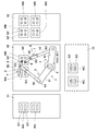
- FIG. 3 is a plan view for illustrating the process of moving the workpiece WA by the robot shown in FIG.
- the workpiece moving member 8 is configured by a suction mechanism in which a suction portion that holds the workpiece WA by being suctioned to the upper surface of the workpiece WA is provided at the tip (lower end).
- the control unit 14 moves the workpieces provided at the respective hands 5 and 6 of the first arm 3 and the second arm 4 at a predetermined position on the upper surface of the workpiece WA placed at a predetermined position on the work table 11.
- the robot 1 is controlled so that the member 8 is positioned and each workpiece moving member 8 is attracted to the workpiece WA. As shown in FIG.
- the predetermined position on the upper surface of the workpiece WA (the suction position of the workpiece moving member 8) is, for example, a region at both ends in the left-right direction in FIG. 3 at the center in the vertical direction in FIG. .
- the control unit 14 does not recognize the workpiece WA itself, stores the suction position as coordinates on the work table 11, and moves each workpiece moving member 8 to the coordinates to position the workpiece WA at the suction position of the workpiece WA.
- the control unit 14 moves the workpiece WA to a predetermined position on the work table 10 while the workpiece moving member 8 is attracted to the workpiece WA as shown in FIG.
- the robot 1 is controlled.
- the control unit 14 determines that the two workpiece moving members 8 have the same height from the placement position of the workpiece WA on the worktable 11 to a predetermined position on the worktable 10.
- the robot 1 is controlled so that the distance between the two workpiece moving members 8 is constant.
- the control unit 14 performs control so that the first arm 3 and the second arm 4 are cooperatively operated in the first control mode.
- the robot 1 is configured as a double-arm robot having two arms 3 and 4.
- a control device for interlocking control of a plurality of robots is required in addition to a control device for controlling each robot. It is necessary to set an interlock condition to operate efficiently.
- the two arms 3 and 4 can be collectively controlled by the control unit 14 of the robot 1. For this reason, it is possible to easily perform control as compared with the case where a plurality of robots each having one arm are cooperatively controlled.
- the suction position of the workpiece moving member 8 on the workpiece WA placed on the work table 11 is completely coincident with the coordinates of the suction position of the workpiece moving member 8 stored in the control unit 14.
- the worker manually places the workpiece WA on the work table 11 (when the upstream process is performed manually)
- a certain amount of positional deviation occurs.
- the suction position of the workpiece moving member 8 on the workpiece WA may deviate from the assumed position. .
- the robot 1 positions the workpiece WA after being transferred to the work table 10.
- the control unit 14 determines the restriction position Pr by the restriction member 7 from the stop position Pw where the work WA is predetermined. Control is performed so that the workpiece WA is moved to a temporary stop position Pw ′ shifted by a predetermined distance in the opposite direction (in this example, the lower right side in FIG. 3).
- the restriction position Pr by the restriction member 7 is set at the upper left corner of the drawing in FIG. 3 of the stop position Pw. Therefore, the restriction member 7 is positioned by placing the workpiece WA on the restriction position Pr. I can't. Accordingly, by setting the position on the work table 10 where the work WA is stopped in the process of moving from the work table 11 to the work table 10 in advance, the position of the work moving member 8 in the actual work WA is set. Even if the suction position deviates from the assumed position to some extent, the positioning operation described later can be executed without resetting the restriction position.
- the robot 1 executes a process of transferring the work WB from the work table 12 to the work table 10 in the same manner as the work WA transfer process from the work table 11 to the work table 10. That is, the control unit 14 positions the work moving members 8 provided on the first arm 3 and the second arm 4 at predetermined positions on the upper surface of the work WB placed at a predetermined position on the work table 12, respectively.
- the robot 1 is controlled to move the workpiece WB to a predetermined position on the work table 10 in a state where each workpiece moving member 8 is attracted to the workpiece WB and the workpiece moving member 8 is attracted to the workpiece WB.
- a temporary stop position may be set with respect to the stop position of the workpiece WB in consideration of a positioning operation described later, and the workpiece WB may be moved to the temporary stop position.
- the control unit 14 moves the workpiece provided on the first hand 5 and the regulating member 7 provided on the second hand 6 as shown in FIG.
- the robot 1 is controlled so that the workpiece 8 is positioned using the member 8.
- the control unit 14 moves the restricting member 7 of one arm to the stop position Pw of the work WA based on predetermined dimension information of the work WA and predetermined stop position information.
- the workpiece moving member 8 is directed to the regulating position Pr so that the workpiece WA is moved horizontally by causing the workpiece moving member 8 of the other arm to act on the workpiece WA by being positioned at a predetermined regulation position Pr (see FIG. 3) included.
- the workpiece WA is controlled to move to the stop position Pw by moving the workpiece WA against the regulating member 7.
- the first arm 3 and the first hand 5 and the second arm 4 and the second hand 6 are independently controlled, and have different effects on one workpiece WA.
- a cooperative operation is performed on one work WA.
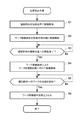
- FIG. 4 is a flowchart showing a processing flow of positioning work in the present embodiment.
- the control unit 14 starts to move the restriction member 7 of the first hand 5 toward a predetermined restriction position Pr included in the stop position Pw of the workpiece WA.
- the first arm 3 is controlled (step S1).
- the restriction position Pr is provided at the upper left corner of the drawing in FIG. 3 of the stop position Pw.
- the regulating member 7 has a first vertical surface 71 perpendicular to the horizontal plane in a state of being placed at the regulating position Pr, and a first vertical plane 71 and a second vertical plane 72 perpendicular to the horizontal plane. .
- the restricting member 7 has a substantially L shape in plan view in a state where it is located at the restricting position Pr.
- the first vertical surface 71 is positioned so as to overlap with one side (left side) of the stop position Pw of the workpiece WA, and the second vertical surface 72 is another side adjacent to the stop position Pw of the workpiece WA ( It is positioned so as to overlap the upper side.
- control unit 14 directs the workpiece moving member 8 to a predetermined moving action position in order to cause the workpiece moving member 8 of the second hand 6 to act on the workpiece WA on the work table 10 to move the workpiece WA horizontally.
- the second arm 4 is controlled to start moving (step S2).
- the control unit 14 moves the hand of the second arm 4 (the second hand) to a predetermined position on the upper surface of the workpiece WA placed at a predetermined position (the temporary stop position Pw ′ described above) of the work table 10.
- the workpiece moving member 8 provided on the hand) 6 is positioned, and the second arm 4 is controlled so that the workpiece moving member 8 is attracted to the workpiece WA.
- the moving action position in the present embodiment is a suction position of the workpiece moving member 8 provided at a predetermined position on the upper surface of the workpiece WA.
- the moving action position is the lower right end area of the work WA in FIG. That is, the moving action position is set as the coordinates of the corner area farthest from the restriction position Pr of the restriction member 7 at the temporary stop position Pw ′ of the workpiece WA.
- the control unit 14 stores the moving action position as coordinates on the work table 10 and moves the workpiece moving member 8 to the coordinates to be positioned at the moving action position.
- the control unit 14 determines whether or not the movement of the restricting member 7 to the restricting position Pr is completed (whether it is located at the restricting position Pr) (step S3).
- the control unit 14 is in a state where the workpiece moving member 8 is attracted to the workpiece WA after the workpiece moving member 8 is attracted to the workpiece WA.
- the second arm 4 is controlled so that the workpiece WA is moved horizontally toward the regulation position Pr by the workpiece moving member 8 (step S4).
- the control unit 14 controls the first arm 3 so as to maintain the restricting member 7 at the restricting position Pr.
- the workpiece WA slides on the work table 10 toward the regulating member 7 located at the regulating position Pr.
- the work WA may be moved in a state of being floated with respect to the upper surface of the work table 10.
- the workpiece moving member 8 is moved to the moving action position, and then the workpiece WA is moved by the workpiece moving member 8 located at the moving action position. May be moved horizontally (processing is executed in the order of steps S1, S3, S2).
- the control unit 14 horizontally moves the workpiece moving member 8 until the workpiece WA comes into contact with the regulating member 7 with the regulating member 7 positioned at the regulating position Pr.
- the control unit 14 determines whether or not the workpiece WA is in contact with the regulating member 7 (step S5). Specifically, the control unit 14 makes contact with either one of the first vertical surface 71 and the second vertical surface 72 in a state where the restriction member 7 is positioned at the restriction position Pr.
- the workpiece WA is horizontally moved in a direction perpendicular to the other of the first vertical surface 71 and the second vertical surface 72 so that the workpiece WA is brought into contact with the other vertical surface.
- the workpiece moving member 8 (second arm 4) is controlled. Thereby, the workpiece WA to be horizontally moved can be surely positioned at the stop position Pw.
- Step S5 When the contact of the workpiece WA with the regulating member 7 is detected (Yes in Step S5), the control unit 14 stops the horizontal movement of the workpiece moving member 8 (Step S6). As a result, the workpiece WA is placed on the stop position Pw of the work table 10.
- the two arms 3 and 4 are controlled independently, and one of the two arms 3 and 4 is arbitrarily positioned by bending the two arms 3 and 4 at respective joints.
- the other arm (second arm 2) of the two arms 3 and 4 while restricting the horizontal movement of the workpiece WA by the restricting member 7 provided on the hand (first hand 5) of the arm (first arm 3)
- the workpiece WA can be controlled to move horizontally to the regulation position Pr regulated by the regulation member 7 with the workpiece movement member 8 provided on the hand (second hand 6) of the arm 4).
- the workpiece WA can be easily positioned without arranging a positioning jig at a predetermined position in advance. Since it is not necessary to provide a positioning jig, it is possible to easily and quickly cope with changes in the workpiece WA and work contents.
- the workpiece WA In order to position the workpiece WA in the horizontal direction, the workpiece WA is independently moved in two directions perpendicular to each other in the horizontal plane (for example, the horizontal direction and the vertical direction in FIG. 1) and positioned in each direction. Necessary. According to the said structure, since the two arms 3 and 4 can each take arbitrary attitude
- the positioning work does not require the accuracy of the placement positions of the workpieces WA and WB on the work tables 11 and 12, the work WA and WB are placed on the work tables 11 and 12. It is also possible to cause the worker to perform the operation, and it is possible to easily construct a work line in which the worker and the robot 1 coexist.
- the workpiece moving member 8 can be moved horizontally in the horizontal plane, an appropriate positioning operation can be performed.
- the positioning work may be similarly performed on the work WB on the work table 10. At this time, the positioning operation may be performed using the regulating member 7 provided on the second hand 6 and the workpiece moving member 8 provided on the first hand 5. Further, the positioning work may be performed on the workpiece WA using the regulating member 7 provided on the second hand 6 and the workpiece moving member 8 provided on the first hand 5. For example, when the restricting position Pr by the restricting member 7 provided on the second hand 6 is set at the upper left corner of FIG. 1 of the stop position Pw of the workpieces WA and WB, the workpieces WA and WB are set to the right side of FIG. Positioning can be performed by horizontally moving in the direction and upward.
- the positioning direction (direction in which the workpieces WA and WB are moved) is provided. ) Can be set in various ways.
- the control unit 14 detects the contact of the workpiece WA with the regulating member 7 by the current or torque change of the motor that drives the joint axes B1, B2, and B3 of the second arm 4. For this purpose, the control unit 14 controls the torque of the motor that drives each joint axis B1, B2, B3 of the second arm 4 in order to move the workpiece moving member 8 horizontally.
- the control unit 14 monitors the torque change of each motor, and determines that the control member 14 is in contact with the regulating member 7 when a predetermined torque threshold is exceeded. Further, the control unit 14 determines the position of the joint shaft of the motor exceeding the torque threshold and the posture of the second arm 4 at that time from the first vertical surface 71 and the second vertical surface 72 of the regulating member 7. It is determined which one of the two has contacted. Accordingly, it is possible to detect contact of the workpiece WA with the regulating member 7 without providing a separate sensor for contact detection.
- control unit 14 determines that the first vertical surface 71 and the second vertical surface 72 are in contact with each other, the position of the workpiece moving member 8 in the direction perpendicular to the contact surface is determined. May be controlled to return a predetermined distance. Thereby, it can prevent that the workpiece
- the joint axes A1, A2, of the first arm 3 are detected.
- a change in torque of the motor driving A3 may be used for contact detection.
- FIG. 5 is a plan view for illustrating the step of producing the workpiece WC by the robot shown in FIG.
- the first arm 3 and the first hand 5 and the second arm 4 and the second hand 6 are independently controlled to perform parallel operations.
- the control unit 14 controls the robot 1 so that each workpiece moving member 8 is attracted to two components Q2 among the plurality of components Q2 arranged on the workpiece WB placed on the work table 10.
- the parts Q2 on the work WB are arranged in a set of two. It is preferable.
- control unit 14 responds among the plurality of components Q1 arranged on the workpiece WA placed on the work table 10 with each workpiece Q2 being attracted to each component Q2.
- the robot 1 is controlled so as to be moved to predetermined positions on the two parts Q1.
- the control unit 14 releases the suction of each workpiece moving member 8 to the component Q2 in a state where each component Q2 is placed at a predetermined position on the corresponding component Q1.
- the time can be shortened by performing the work of attaching the parts Q2 two by two using the two arms 3 and 4.
- the same operation is repeated. Further, when the number of parts Q1 arranged on the work WA is different from the number of parts Q2 arranged on the work WB, the work having no parts on the work is moved to another work table, and the work table 11 Alternatively, a new work WA or WB is moved from 12.
- the control unit 14 works to position the work WC (former work WA) behind the robot 1.
- the robot 1 is controlled to be moved to a predetermined position on the table 13.
- the transfer mode of the work WC is the same as the transfer process of the work WA described with reference to FIG.
- the workpiece moving member 8 has been described as using a suction mechanism.
- the present invention is not limited to this, and various workpiece moving members can be applied.
- various workpiece holding structures such as a gripping mechanism that moves the workpiece by gripping the end portion of the workpiece can be applied.
- FIG. 6 is an enlarged plan view showing a modification in which the regulating member is operated as a workpiece moving member in the robot shown in FIG.
- the regulating member 7 is caused to function as the workpiece moving member 8, and the workpiece is moved by pushing the end portion (corner portion) of the workpiece WA from the side by the regulating member 7.
- the workpiece moving member itself has an effect of regulating the position, both sides of the workpiece can be regulated, and highly accurate positioning can be performed.
- both restricting members 7 may function as the workpiece moving member 8. For example, after arranging the two regulating members 7 at a predetermined interval so that each regulating member 7 is located on the diagonal line of the stopping position Pw of the workpiece WA and sandwiching the stopping position Pw, the regulating member 7 is located outside the stopping position Pw.
- the two restricting members 7 may be moved so that the interval on the diagonal line is narrowed.
- the predetermined interval is set as a length such that the workpiece WA is placed within the predetermined interval.
- the regulating member 7 that first contacts the workpiece WA functions as the workpiece moving member 8.
- any one of the two restriction members 7 may have a plate-like configuration having only one vertical surface.
- the SCARA robot horizontal articulated robot in which the joint axes of the two arms 3 and 4 are all perpendicular to the horizontal plane has been described.
- it is used in a 6-axis articulated robot or the like.
- the present invention can also be applied to a robot having a plurality of arms that can three-dimensionally control the position of a simple hand.
- shaft of the arms 3 and 4 was illustrated as an aspect which detects contact
- work moving member 8 were demonstrated previously in the 1st hand 5 and the 2nd hand 6, the control member 7 and the workpiece
- the robot 1 performs work on the workpiece in a state of being provided on the first hand 5 and / or the second hand 6.
- the regulating member 7 and / or the workpiece moving member 8 may be configured to be detachable from the first hand 5 and the second hand 6.
- the regulating member 7 and / or the workpiece moving member 8 are placed at a predetermined location, and the robot 1 places the placed regulating member 7 and / or the workpiece moving member 8 on the corresponding hands 5 and 6.
- the work performed on the workpiece by the robot 1 is a work for regulating the horizontal movement of the workpiece in the regulating member 7 and an operation for causing the workpiece to move horizontally in the workpiece moving member 8.
- the shape of the restricting member 7 is not limited thereto. I can't.
- the regulating member 7 may be constituted by a pin-shaped member.
- FIG. 7A is a perspective view showing a restricting member in a modification of the present embodiment
- FIG. 7B is an enlarged plan view showing an example of a restricting mode using the restricting member shown in FIG. 7A.
- the restricting member 7A includes a pair of left and right pin-like portions 73 and 74 arranged in parallel with a predetermined interval, and a connecting portion 75 that connects the pair of left and right pin-like members 73 and 74 to each other.
- the connecting portion 75 is attached to the first hand 5.
- the shape of the connection part 75 has a U-shaped shape in the example of FIG.
- the shape is not particularly limited as long as the connection part 75 does not contact the workpiece.
- the connecting portion 75 may have a shape that linearly connects the pin-like portions 73 and 74.
- the connecting portion 75 is configured to be connected to the central portion in the longitudinal direction of the pin-like portions 73 and 74. That is, the pin-like portions 73 and 74 extend upward and downward from the connecting portion 75.
- the connecting portion 75 may be connected to the upper ends of the pin-like portions 73 and 74, and the pin-like portions 73 and 74 may be extended downward from the connecting portion 75.
- the control unit 14 performs movement and stop control so that the pin-like portions 73 and 74 of the regulating member 7A are positioned so as to be in contact with two sides sandwiching the corner of the stop position Pw of the workpiece WA. . Accordingly, when the workpiece WA is moved by the workpiece moving member 8 and is positioned at the stop position Pw, the workpiece WA comes into contact with the pin-like portions 73 and 74 of the regulating member 7A, and the position of the workpiece WA is regulated to the stop position Pw. (Positioning).
- any one of the two regulating members 7A may have a plate-like configuration having one vertical surface.
- the workpiece may be positioned.
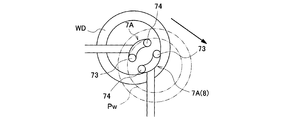
- FIG. 7C is an enlarged plan view showing another example of a restricting mode using the restricting member shown in FIG. 7A.
- FIG. 7C illustrates a mode in which the ring-shaped workpiece WD is positioned at the stop position Pw.
- the control unit 14 causes one of the regulating members 7A to function as the workpiece moving member 8, and moves the workpiece by pushing the inner peripheral surface of the workpiece WD from the side with the regulating member 7A. Furthermore, the control unit 14 performs movement and stop control so that the pin-like portions 73 and 74 of the other restricting member 7A are located at a restricting position where they contact the inner periphery of the stop position Pw of the work WD.
- the workpiece WD In a state where the workpiece WD is located at the stop position Pw, the workpiece WD is positioned in a state where the four points on the inner periphery are in contact with the pin-like portions 73 and 74 of the two regulating members 7A.
- the control unit 14 determines the other regulating member 7A. Is controlled so as to be positioned at the restriction position. That is, after the positional relationship is such that the two regulating members 7A are separated from each other (the positional relationship such that the two hands 5 and 6 do not cross), the other regulating member 7A is positioned at the regulated position. Accordingly, it is possible to prevent the other restricting member 7A from coming into contact with the outer periphery of the work WD and erroneously restricting the movement of the work WD to the stop position Pw.
- one of the two regulating members 7A may be a regulating member having one pin-shaped portion.
- a regulating member having one pin-shaped portion may function as the workpiece moving member 8
- a regulating member 7 ⁇ / b> A having two pin-shaped portions 73 and 74 may function as the workpiece moving member 8.
- the workpiece WD is positioned in a state where the three points on the inner periphery are in contact with the pin-shaped portions of the two regulating members.
- the robot 1 may be configured to be able to attach a plurality of types of regulating members 7 and / or a plurality of types of workpiece moving members 8 to the corresponding hands 5 and 6. Selection and replacement of the plurality of types of regulating members 7 and / or the plurality of types of workpiece moving members 8 may be performed manually or may be controlled so that the robot 1 itself selects and attaches / detaches as described above.
- the robot of the present invention is useful for easily positioning a workpiece without disposing a positioning jig at a predetermined position.
Landscapes
- Engineering & Computer Science (AREA)
- Robotics (AREA)
- Mechanical Engineering (AREA)
- Health & Medical Sciences (AREA)
- General Health & Medical Sciences (AREA)
- Orthopedic Medicine & Surgery (AREA)
- Human Computer Interaction (AREA)
- Manipulator (AREA)
- Automatic Assembly (AREA)
Abstract
Description
2 基台
3 第1のアーム
4 第2のアーム
5 第1の手先
6 第2の手先
7,7A 規制部材
8 ワーク移動部材
14 制御部
71 第1の垂直面
72 第2の垂直面
C 回動軸(基台に垂直な軸)
WA,WB,WC,WD ワーク
Claims (5)
- 先端に設けられた第1の手先と、基台と前記第1の手先との間に設けられた少なくとも1つの関節軸とを有する第1のアームと、
先端に設けられた第2の手先と、前記基台と前記第2の手先との間に設けられた少なくとも1つの関節軸とを有する第2のアームと、
前記第1のアームおよび前記第2のアームのそれぞれを制御する制御部と、
前記第1の手先に設けられた状態で、所定のワークの水平移動を規制するための規制部材と、
前記第2の手先に設けられた状態で、前記ワークを水平移動させるための作用を生じるワーク移動部材と、を備え、
前記制御部は、前記ワークの所定の寸法情報および予め定められた停止位置情報に基づいて、前記規制部材を前記ワークの停止位置に含まれる所定の規制位置に位置させ、前記ワーク移動部材を前記ワークに作用させて前記ワークが水平移動するように前記ワーク移動部材を前記規制位置に向けて動かし、前記ワークを前記規制部材に当接させることにより前記ワークが前記停止位置に位置するように制御する、ロボット。 - 前記第1のアームおよび前記第2のアームのそれぞれは、前記基台に垂直な軸に同軸に配置されかつ前記基台に対して独立して前記軸回りに回動可能に構成される、請求項1に記載のロボット。
- 前記規制部材は、前記規制位置に位置した状態で水平面に垂直な第1の垂直面と、当該第1の垂直面および前記水平面に垂直な第2の垂直面と、を有する、請求項1または2に記載のロボット。
- 前記制御部は、前記規制部材を前記規制位置に位置させた状態で、前記第1の垂直面および前記第2の垂直面のうちの何れか一方の垂直面への当接を検知した場合に、前記ワークを前記第1の垂直面および前記第2の垂直面のうちの他方の垂直面に垂直な方向に水平移動させて前記ワークを前記他方の垂直面に当接させるように前記ワーク移動部材を制御する、請求項3に記載のロボット。
- 前記制御部は、前記ワークの前記規制部材への当接を前記第1のアームおよび前記第2のアームの少なくとも何れか一方が有する関節軸を駆動するモータの電流またはトルク変化によって検知する、請求項1から4の何れかに記載のロボット。
Priority Applications (8)
| Application Number | Priority Date | Filing Date | Title |
|---|---|---|---|
| KR1020177018483A KR101952767B1 (ko) | 2014-12-26 | 2014-12-26 | 로봇 |
| US15/537,689 US10406681B2 (en) | 2014-12-26 | 2014-12-26 | Robot |
| JP2016565600A JP6329645B2 (ja) | 2014-12-26 | 2014-12-26 | ロボット |
| PCT/JP2014/006483 WO2016103300A1 (ja) | 2014-12-26 | 2014-12-26 | ロボット |
| CN201480084345.8A CN107000203B (zh) | 2014-12-26 | 2014-12-26 | 机械臂 |
| EP14908911.2A EP3238883B1 (en) | 2014-12-26 | 2014-12-26 | Robot |
| SG11201703889XA SG11201703889XA (en) | 2014-12-26 | 2014-12-26 | Robot |
| TW104118732A TWI581928B (zh) | 2014-12-26 | 2015-06-10 | Mechanical arm |
Applications Claiming Priority (1)
| Application Number | Priority Date | Filing Date | Title |
|---|---|---|---|
| PCT/JP2014/006483 WO2016103300A1 (ja) | 2014-12-26 | 2014-12-26 | ロボット |
Publications (1)
| Publication Number | Publication Date |
|---|---|
| WO2016103300A1 true WO2016103300A1 (ja) | 2016-06-30 |
Family
ID=56149404
Family Applications (1)
| Application Number | Title | Priority Date | Filing Date |
|---|---|---|---|
| PCT/JP2014/006483 Ceased WO2016103300A1 (ja) | 2014-12-26 | 2014-12-26 | ロボット |
Country Status (8)
| Country | Link |
|---|---|
| US (1) | US10406681B2 (ja) |
| EP (1) | EP3238883B1 (ja) |
| JP (1) | JP6329645B2 (ja) |
| KR (1) | KR101952767B1 (ja) |
| CN (1) | CN107000203B (ja) |
| SG (1) | SG11201703889XA (ja) |
| TW (1) | TWI581928B (ja) |
| WO (1) | WO2016103300A1 (ja) |
Cited By (3)
| Publication number | Priority date | Publication date | Assignee | Title |
|---|---|---|---|---|
| WO2021006175A1 (ja) * | 2019-07-05 | 2021-01-14 | 川崎重工業株式会社 | 搬送ロボット |
| WO2022259706A1 (ja) * | 2021-06-09 | 2022-12-15 | 東京計器株式会社 | 接触検知装置 |
| JP7330344B1 (ja) | 2022-10-31 | 2023-08-21 | カワダロボティクス株式会社 | スティック状梱包品のピッキングシステムおよび二次梱包システム |
Families Citing this family (10)
| Publication number | Priority date | Publication date | Assignee | Title |
|---|---|---|---|---|
| CN106078710B (zh) * | 2016-07-06 | 2018-03-06 | 英华达(上海)科技有限公司 | 多任务应用的多轴机器人 |
| CN106181982A (zh) * | 2016-08-09 | 2016-12-07 | 英华达(上海)科技有限公司 | 多轴机器人 |
| US11065760B2 (en) | 2016-08-09 | 2021-07-20 | Inventec Appliances (Pudong) Corporation | Multiaxial robot with cover |
| JP6845671B2 (ja) * | 2016-11-30 | 2021-03-24 | 川崎重工業株式会社 | 部品実装装置及びその制御方法 |
| JP6831739B2 (ja) * | 2017-04-03 | 2021-02-17 | 川崎重工業株式会社 | 蓋閉じ装置及び蓋閉じ方法 |
| WO2019039006A1 (ja) * | 2017-08-23 | 2019-02-28 | ソニー株式会社 | ロボット |
| CN108036951A (zh) * | 2017-10-26 | 2018-05-15 | 安徽瑞林精科股份有限公司 | 一种汽车排挡杆检测装置 |
| CN108000087A (zh) * | 2017-10-26 | 2018-05-08 | 安徽瑞林精科股份有限公司 | 一种汽车零部件组装检测设备 |
| US11591170B2 (en) * | 2019-10-25 | 2023-02-28 | Dexai Robotics, Inc. | Robotic systems and methods for conveyance of items |
| CN111975341B (zh) * | 2020-09-10 | 2024-07-26 | 川崎(重庆)机器人工程有限公司 | 变速箱壳体螺钉上下料双腕机器人系统 |
Citations (5)
| Publication number | Priority date | Publication date | Assignee | Title |
|---|---|---|---|---|
| WO2011155575A1 (ja) * | 2010-06-11 | 2011-12-15 | 株式会社安川電機 | サービス提供システム及びサービス提供方法 |
| JP2013505147A (ja) * | 2009-09-22 | 2013-02-14 | ジーエム・グローバル・テクノロジー・オペレーションズ・インコーポレーテッド | 人間型ロボット |
| JP2013198955A (ja) * | 2012-03-23 | 2013-10-03 | Toyota Motor East Japan Inc | ロボット接触検知装置 |
| JP2014046419A (ja) * | 2012-08-31 | 2014-03-17 | Yaskawa Electric Corp | ロボットおよびロボットシステム |
| WO2014125627A1 (ja) * | 2013-02-15 | 2014-08-21 | 株式会社安川電機 | 梱包装置および梱包方法 |
Family Cites Families (25)
| Publication number | Priority date | Publication date | Assignee | Title |
|---|---|---|---|---|
| JPH0259291A (ja) * | 1988-08-26 | 1990-02-28 | Matsushita Electric Ind Co Ltd | ロボットアームの衝突検出方法 |
| US5125789A (en) * | 1990-01-02 | 1992-06-30 | Peerless Automation | Molded parts removal and transfer robot |
| JP3448952B2 (ja) | 1994-04-13 | 2003-09-22 | ソニー株式会社 | 双腕ロボット |
| JPH09198121A (ja) * | 1996-01-19 | 1997-07-31 | Nippon Telegr & Teleph Corp <Ntt> | ロボット教示方法 |
| JPH09319425A (ja) | 1996-05-29 | 1997-12-12 | Kobe Steel Ltd | 部品の組立方法及び組立装置 |
| US6489741B1 (en) * | 1998-08-25 | 2002-12-03 | Genmark Automation, Inc. | Robot motion compensation system |
| JP2003053687A (ja) * | 2001-08-16 | 2003-02-26 | Fuji Photo Film Co Ltd | 作業ロボットのワークハンドリング方法 |
| CN101890720B (zh) * | 2004-07-13 | 2012-01-11 | 松下电器产业株式会社 | 物品保持系统、机器人以及机器人控制方法 |
| JP2006035346A (ja) * | 2004-07-23 | 2006-02-09 | Toyota Motor Corp | 部品組付け方法 |
| JP2010099784A (ja) * | 2008-10-24 | 2010-05-06 | Honda Motor Co Ltd | ピン嵌合方法及びピン引き抜き方法 |
| JP2010162669A (ja) | 2009-01-19 | 2010-07-29 | Olympus Corp | 生産装置 |
| JP5810582B2 (ja) * | 2011-03-29 | 2015-11-11 | セイコーエプソン株式会社 | ロボットの制御方法、及びロボット |
| JP5161335B2 (ja) * | 2011-04-06 | 2013-03-13 | 中外炉工業株式会社 | 基板の搬送装置及びこれを備えた基板の加工装置 |
| JP5818345B2 (ja) * | 2011-04-27 | 2015-11-18 | 日本電産サンキョー株式会社 | 回転機構、産業用ロボットおよび回転体の原点位置復帰方法 |
| WO2012163390A1 (en) * | 2011-05-27 | 2012-12-06 | Abb Technology Ag | A configurable handling tool system |
| JP5494617B2 (ja) * | 2011-10-26 | 2014-05-21 | 株式会社安川電機 | ロボットシステムおよび加工品の製造方法 |
| JP2013099807A (ja) | 2011-11-08 | 2013-05-23 | Seiko Epson Corp | ロボット及びロボットの制御方法 |
| JP5917380B2 (ja) | 2012-12-04 | 2016-05-11 | 川田工業株式会社 | 多関節型ロボットによるワーク位置決め方法およびそのワーク位置決め方法を用いた多関節型ロボットによるワーク装着方法 |
| JP5750472B2 (ja) * | 2013-05-22 | 2015-07-22 | 株式会社安川電機 | 基板搬送ロボット、基板搬送システムおよび基板の配置状態の検出方法 |
| US20150032258A1 (en) * | 2013-07-29 | 2015-01-29 | Brain Corporation | Apparatus and methods for controlling of robotic devices |
| JP2015085479A (ja) * | 2013-11-01 | 2015-05-07 | セイコーエプソン株式会社 | ロボット、制御装置、ロボットシステム、及びロボット制御方法 |
| JP2015085494A (ja) | 2013-11-01 | 2015-05-07 | セイコーエプソン株式会社 | ロボット、制御装置、ロボットシステム及びロボット制御方法 |
| CN103722549B (zh) * | 2013-12-31 | 2015-08-19 | 重庆交通大学 | 空间协作重载精密双臂机械手 |
| US9349629B2 (en) * | 2014-01-23 | 2016-05-24 | Lam Research Corporation | Touch auto-calibration of process modules |
| CN203875649U (zh) * | 2014-05-06 | 2014-10-15 | 宁波市海通汽车配件有限公司 | 一种汽车柱形工件加工夹具 |
-
2014
- 2014-12-26 US US15/537,689 patent/US10406681B2/en active Active
- 2014-12-26 JP JP2016565600A patent/JP6329645B2/ja active Active
- 2014-12-26 CN CN201480084345.8A patent/CN107000203B/zh active Active
- 2014-12-26 SG SG11201703889XA patent/SG11201703889XA/en unknown
- 2014-12-26 WO PCT/JP2014/006483 patent/WO2016103300A1/ja not_active Ceased
- 2014-12-26 KR KR1020177018483A patent/KR101952767B1/ko active Active
- 2014-12-26 EP EP14908911.2A patent/EP3238883B1/en active Active
-
2015
- 2015-06-10 TW TW104118732A patent/TWI581928B/zh active
Patent Citations (5)
| Publication number | Priority date | Publication date | Assignee | Title |
|---|---|---|---|---|
| JP2013505147A (ja) * | 2009-09-22 | 2013-02-14 | ジーエム・グローバル・テクノロジー・オペレーションズ・インコーポレーテッド | 人間型ロボット |
| WO2011155575A1 (ja) * | 2010-06-11 | 2011-12-15 | 株式会社安川電機 | サービス提供システム及びサービス提供方法 |
| JP2013198955A (ja) * | 2012-03-23 | 2013-10-03 | Toyota Motor East Japan Inc | ロボット接触検知装置 |
| JP2014046419A (ja) * | 2012-08-31 | 2014-03-17 | Yaskawa Electric Corp | ロボットおよびロボットシステム |
| WO2014125627A1 (ja) * | 2013-02-15 | 2014-08-21 | 株式会社安川電機 | 梱包装置および梱包方法 |
Non-Patent Citations (1)
| Title |
|---|
| See also references of EP3238883A4 * |
Cited By (6)
| Publication number | Priority date | Publication date | Assignee | Title |
|---|---|---|---|---|
| WO2021006175A1 (ja) * | 2019-07-05 | 2021-01-14 | 川崎重工業株式会社 | 搬送ロボット |
| JP2021010967A (ja) * | 2019-07-05 | 2021-02-04 | 川崎重工業株式会社 | 搬送ロボット |
| JP7223655B2 (ja) | 2019-07-05 | 2023-02-16 | 川崎重工業株式会社 | 搬送ロボット |
| WO2022259706A1 (ja) * | 2021-06-09 | 2022-12-15 | 東京計器株式会社 | 接触検知装置 |
| JP7330344B1 (ja) | 2022-10-31 | 2023-08-21 | カワダロボティクス株式会社 | スティック状梱包品のピッキングシステムおよび二次梱包システム |
| JP2024065921A (ja) * | 2022-10-31 | 2024-05-15 | カワダロボティクス株式会社 | スティック状梱包品のピッキングシステムおよび二次梱包システム |
Also Published As
| Publication number | Publication date |
|---|---|
| EP3238883A1 (en) | 2017-11-01 |
| CN107000203A (zh) | 2017-08-01 |
| KR101952767B1 (ko) | 2019-02-28 |
| EP3238883A4 (en) | 2018-10-10 |
| TWI581928B (zh) | 2017-05-11 |
| KR20170091734A (ko) | 2017-08-09 |
| JPWO2016103300A1 (ja) | 2017-08-10 |
| EP3238883B1 (en) | 2020-12-09 |
| CN107000203B (zh) | 2020-04-10 |
| US20180015613A1 (en) | 2018-01-18 |
| US10406681B2 (en) | 2019-09-10 |
| TW201622910A (zh) | 2016-07-01 |
| SG11201703889XA (en) | 2017-06-29 |
| JP6329645B2 (ja) | 2018-05-23 |
Similar Documents
| Publication | Publication Date | Title |
|---|---|---|
| JP6329645B2 (ja) | ロボット | |
| US9156160B2 (en) | Robot system, calibration method, and method for producing to-be-processed material | |
| JP6450960B2 (ja) | ロボット、ロボットシステム及び教示方法 | |
| CN104589354B (zh) | 机器人控制装置、机器人系统以及机器人 | |
| CN102892557B (zh) | 机器人单位设备和生产系统 | |
| CN104552285B (zh) | 机器人、机器人控制装置以及机器人系统 | |
| JP6330287B2 (ja) | ロボット、ロボット用当接部材 | |
| CN106493711B (zh) | 控制装置、机器人以及机器人系统 | |
| CN104044131A (zh) | 机器人系统、校正方法及被加工物制造方法 | |
| JP6208601B2 (ja) | ワーク位置決め機能を有するロボットハンド、ロボットシステム、及びワークの位置決め把持方法 | |
| CN108349092A (zh) | 制造系统、制造系统的构建方法、末端效应器、机器人、及机器人的作业方法 | |
| WO2019159713A1 (ja) | 接続装置及び接続方法 | |
| US20160318179A1 (en) | Robot system | |
| CN107962563A (zh) | 控制装置、机器人以及机器人系统 | |
| CN107428012A (zh) | 机械手、机械手的控制方法、工件的安装方法以及工件的搬运方法 | |
| CN111195920B (zh) | 工件把持机械手、机械手系统和机器人系统 | |
| CN110024509A (zh) | 部件安装装置及其控制方法 | |
| JP2015096290A (ja) | ロボット、ロボットシステム、ロボット制御装置及び方法 | |
| JP2015085480A (ja) | ロボット、制御装置、ロボットシステム、ロボット制御方法、及びプログラム | |
| JP6314431B2 (ja) | ロボットシステム、制御装置、ロボット、及び駆動方法 | |
| JP2015085457A (ja) | ロボット、ロボットシステム及びロボット制御装置 | |
| US20230028767A1 (en) | Position detection method, controller, and robot system | |
| CN109803797B (zh) | 机器人 |
Legal Events
| Date | Code | Title | Description |
|---|---|---|---|
| 121 | Ep: the epo has been informed by wipo that ep was designated in this application |
Ref document number: 14908911 Country of ref document: EP Kind code of ref document: A1 |
|
| ENP | Entry into the national phase |
Ref document number: 2016565600 Country of ref document: JP Kind code of ref document: A |
|
| WWE | Wipo information: entry into national phase |
Ref document number: 11201703889X Country of ref document: SG |
|
| WWE | Wipo information: entry into national phase |
Ref document number: 15537689 Country of ref document: US |
|
| NENP | Non-entry into the national phase |
Ref country code: DE |
|
| ENP | Entry into the national phase |
Ref document number: 20177018483 Country of ref document: KR Kind code of ref document: A |
|
| REEP | Request for entry into the european phase |
Ref document number: 2014908911 Country of ref document: EP |