WO2016103441A1 - 室外機 - Google Patents
室外機 Download PDFInfo
- Publication number
- WO2016103441A1 WO2016103441A1 PCT/JP2014/084489 JP2014084489W WO2016103441A1 WO 2016103441 A1 WO2016103441 A1 WO 2016103441A1 JP 2014084489 W JP2014084489 W JP 2014084489W WO 2016103441 A1 WO2016103441 A1 WO 2016103441A1
- Authority
- WO
- WIPO (PCT)
- Prior art keywords
- panel
- outdoor unit
- heat exchanger
- disposed
- outdoor
- Prior art date
- Legal status (The legal status is an assumption and is not a legal conclusion. Google has not performed a legal analysis and makes no representation as to the accuracy of the status listed.)
- Ceased
Links
Images


Classifications
-
- F—MECHANICAL ENGINEERING; LIGHTING; HEATING; WEAPONS; BLASTING
- F24—HEATING; RANGES; VENTILATING
- F24F—AIR-CONDITIONING; AIR-HUMIDIFICATION; VENTILATION; USE OF AIR CURRENTS FOR SCREENING
- F24F1/00—Room units for air-conditioning, e.g. separate or self-contained units or units receiving primary air from a central station
- F24F1/06—Separate outdoor units, e.g. outdoor unit to be linked to a separate room comprising a compressor and a heat exchanger
- F24F1/46—Component arrangements in separate outdoor units
- F24F1/48—Component arrangements in separate outdoor units characterised by air airflow, e.g. inlet or outlet airflow
-
- F—MECHANICAL ENGINEERING; LIGHTING; HEATING; WEAPONS; BLASTING
- F24—HEATING; RANGES; VENTILATING
- F24F—AIR-CONDITIONING; AIR-HUMIDIFICATION; VENTILATION; USE OF AIR CURRENTS FOR SCREENING
- F24F1/00—Room units for air-conditioning, e.g. separate or self-contained units or units receiving primary air from a central station
- F24F1/06—Separate outdoor units, e.g. outdoor unit to be linked to a separate room comprising a compressor and a heat exchanger
- F24F1/26—Refrigerant piping
- F24F1/32—Refrigerant piping for connecting the separate outdoor units to indoor units
-
- F—MECHANICAL ENGINEERING; LIGHTING; HEATING; WEAPONS; BLASTING
- F24—HEATING; RANGES; VENTILATING
- F24F—AIR-CONDITIONING; AIR-HUMIDIFICATION; VENTILATION; USE OF AIR CURRENTS FOR SCREENING
- F24F1/00—Room units for air-conditioning, e.g. separate or self-contained units or units receiving primary air from a central station
- F24F1/06—Separate outdoor units, e.g. outdoor unit to be linked to a separate room comprising a compressor and a heat exchanger
- F24F1/26—Refrigerant piping
- F24F1/34—Protection means thereof, e.g. covers for refrigerant pipes
-
- F—MECHANICAL ENGINEERING; LIGHTING; HEATING; WEAPONS; BLASTING
- F24—HEATING; RANGES; VENTILATING
- F24F—AIR-CONDITIONING; AIR-HUMIDIFICATION; VENTILATION; USE OF AIR CURRENTS FOR SCREENING
- F24F1/00—Room units for air-conditioning, e.g. separate or self-contained units or units receiving primary air from a central station
- F24F1/06—Separate outdoor units, e.g. outdoor unit to be linked to a separate room comprising a compressor and a heat exchanger
- F24F1/46—Component arrangements in separate outdoor units
-
- F—MECHANICAL ENGINEERING; LIGHTING; HEATING; WEAPONS; BLASTING
- F24—HEATING; RANGES; VENTILATING
- F24F—AIR-CONDITIONING; AIR-HUMIDIFICATION; VENTILATION; USE OF AIR CURRENTS FOR SCREENING
- F24F1/00—Room units for air-conditioning, e.g. separate or self-contained units or units receiving primary air from a central station
- F24F1/06—Separate outdoor units, e.g. outdoor unit to be linked to a separate room comprising a compressor and a heat exchanger
- F24F1/56—Casing or covers of separate outdoor units, e.g. fan guards
-
- F—MECHANICAL ENGINEERING; LIGHTING; HEATING; WEAPONS; BLASTING
- F24—HEATING; RANGES; VENTILATING
- F24F—AIR-CONDITIONING; AIR-HUMIDIFICATION; VENTILATION; USE OF AIR CURRENTS FOR SCREENING
- F24F13/00—Details common to, or for air-conditioning, air-humidification, ventilation or use of air currents for screening
- F24F13/20—Casings or covers
Definitions
- the present invention relates to an outdoor unit of a refrigeration cycle apparatus.
- an outdoor unit of a refrigeration cycle apparatus such as an air conditioner
- a compressor, a heat exchanger, a blower, and the like are housed inside the casing.
- the outdoor unit of the air conditioner is connected to an indoor unit in which a heat exchanger, a blower, and the like are accommodated via a refrigerant pipe.
- the air conditioner when the blower is driven, outside air is supplied to the heat exchanger, and when the compressor is driven, the refrigerant circulates between the indoor unit and the outdoor unit.
- the shape of the bottom panel is a rectangle, and a flat side panel is provided at a position corresponding to the short side.
- the side panel constitutes a casing on one side of the casing, and is provided with a valve to which a refrigerant pipe drawn from the indoor unit side is connected.
- ⁇ Outdoor units for air conditioners are generally installed outdoors.
- the outdoor unit when installing an outdoor unit in an apartment, the outdoor unit is installed on a veranda.
- a veranda In a detached house, it is easy to secure an installation space for an outdoor unit such as a garden.
- a condominium veranda In a condominium veranda, it is often narrower than a detached house, and the installation space tends to be limited.
- indoor units installed indoors but also outdoor units installed outdoors have a desire to reduce the size.
- the outdoor unit is provided with a valve to which a refrigerant pipe is connected.
- a valve to which a refrigerant pipe is connected.
- the present invention has been made to solve the above-described problems, and an object thereof is to provide an outdoor unit that can be reduced in size.
- An outdoor unit is an outdoor unit to which a refrigerant pipe used for circulating refrigerant between the indoor unit and a compressor and an outdoor heat exchanger is mounted.
- a rectangular bottom panel that is disposed below the heat exchanger and supports the compressor and the outdoor heat exchanger, a peripheral panel that is disposed on a peripheral portion of the bottom panel and is erected on the bottom panel, and a peripheral surface It is provided with the fixed panel which is arrange
- the outdoor unit according to the present invention has the above configuration, the size can be reduced.
- FIG. 1 is a schematic diagram of an air conditioner 200 including an outdoor unit 100 according to the present embodiment.
- FIG. 1A shows an example of a refrigerant circuit configuration of the air conditioner 200
- FIG. 1B shows a state in which the outdoor unit 100 and the indoor unit 150 are connected by a refrigerant pipe P.
- the refrigeration cycle apparatus is the air conditioner 200.
- the air conditioner 200 includes an indoor unit 150 and an outdoor unit 100, which are connected by a refrigerant pipe P.
- the indoor unit 150 includes an indoor heat exchanger 151 that functions as an evaporator during cooling operation and functions as a condenser during heating operation.
- the cold or warm heat generated by the outdoor unit 100 is delivered to the indoor unit 150 via the refrigerant pipe P.
- the outdoor unit 100 is disposed outside, for example, a building, a condominium, a detached house, and the like, and supplies cold or hot heat to the indoor unit 150 through the refrigerant pipe P.
- the outdoor unit 100 includes a compressor 4 that compresses the refrigerant, a four-way valve 8 that switches the flow path, a throttle device 9 that decompresses the refrigerant, an outdoor heat exchanger 2 that exchanges heat between the air and the refrigerant, and an outdoor heat exchanger.
- a blower 3 for supplying air to 2 is mounted.
- the indoor unit 150 is disposed at a position where cooling air or heating air can be supplied to the air-conditioning target space, such as indoors, and supplies the cooling air or heating air to the air-conditioning target space.
- the indoor unit 150 is equipped with an indoor heat exchanger 151 that exchanges heat between air and refrigerant, and a blower 152 that supplies air to the indoor heat exchanger 151.
- the indoor heat exchanger 151 performs heat exchange between the indoor air taken into the indoor unit 150 by the blower 152 and the refrigerant, condenses and liquefies the refrigerant during the heating operation, and evaporates the refrigerant during the cooling operation. is there.
- the four-way valve 8 switches the refrigerant flow during the heating operation and the refrigerant flow during the cooling operation and the defrosting operation.
- the four-way valve 8 connects the discharge side of the compressor 4 and the indoor heat exchanger 151 and also connects the suction side of the compressor 4 and the outdoor heat exchanger 2 during heating operation.
- the expansion device 9 expands the refrigerant flowing through the refrigerant circuit by reducing the pressure.
- One of the expansion devices 9 is connected to the outdoor heat exchanger 2 and the other is connected to the indoor heat exchanger 151.
- the expansion device 9 may be configured by a device whose opening degree can be variably controlled, for example, an electronic expansion valve. Other configurations (such as the compressor 4) will be described later.
- the flow path of the four-way valve 8 is switched as shown in FIG.
- the gaseous refrigerant compressed and discharged by the compressor 4 flows into the indoor heat exchanger 151 via the four-way valve 8.
- the gaseous refrigerant that has flowed into the indoor heat exchanger 151 is condensed by exchanging heat with the indoor air supplied from the blower 152 and flows out of the indoor heat exchanger 151.
- the refrigerant that has flowed out of the indoor heat exchanger 151 flows into the expansion device 9 and is expanded and depressurized by the expansion device 9.
- the decompressed refrigerant flows into the outdoor heat exchanger 2, undergoes heat exchange with the outdoor air supplied from the blower 3, vaporizes, and flows out of the outdoor heat exchanger 2.
- the gaseous refrigerant flowing out from the outdoor heat exchanger 2 is sucked into the compressor 4 through the four-way valve 8.
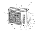
- FIG. 2A is a perspective view of the outdoor unit 100 according to the present embodiment.
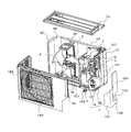
- FIG. 2B is a perspective view of the outdoor unit 100 according to the present embodiment in an exploded state.
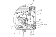
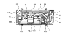
- FIG. 2C is a horizontal sectional view of the outdoor unit 100 according to the present embodiment.
- FIG. 2D is an enlarged view of region B shown in FIG. 2C.
- the outdoor unit 100 includes an outdoor heat exchanger 2 that functions as a condenser during a cooling operation and functions as an evaporator during a heating operation.
- the front panel 1B is defined as the front (front) of the outdoor unit, the side on which the first side panel 1CC is disposed toward the front is defined as the left side, and the second side toward the front.
- the side on which the panel 1C is disposed is defined as the right side.
- the casing of the outdoor unit 100 includes a top panel 1A that configures the upper surface of the outdoor unit 100, a front panel 1B that configures the front of the outdoor unit 100, and a first side panel 1CC that configures the left side of the outdoor unit 100.
- a second side panel 1C constituting the right side surface of the outdoor unit 100, a fan grill 1B2 provided on the front panel 1B and constituting a part of the front surface of the outdoor unit 100, and a bottom surface of the outdoor unit 100.
- a bottom panel 1E a bottom panel 1E.
- the 1st side panel 1CC, the front panel 1B, and the 2nd side panel 1C are the structures corresponding to a surrounding surface panel.
- the outdoor unit 100 includes a partition plate 5 that divides a space in the outdoor unit 100 into a left side and a right side, a compressor 4 that compresses and discharges refrigerant, an outdoor heat exchanger 2 that has an L-shaped horizontal cross section, an outdoor unit A blower 3 for supplying outside air to the heat exchanger 2 and a motor support 3A for holding the blower 3 are mounted.
- the outdoor unit 100 is also equipped with an electrical component box 6 provided with a control device for controlling the number of rotations of the four-way valve 8 and the compressor 4.
- the outdoor unit 100 is disposed at a corner C of the bottom panel 1E so as to be located inside the peripheral panel, and is fixed to the fixed panel 1F standing on the bottom panel 1E, the fixed panel 1F, and the refrigerant pipe P Are connected to each other, and a cover 1D attached to cover the valve 7 is provided.
- the top panel 1 ⁇ / b> A constitutes the upper surface of the outdoor unit 100.
- the top panel 1 ⁇ / b> A is provided at the upper end of the peripheral panel so as to cover the top of the outdoor heat exchanger 2.
- the top panel 1A is provided such that the front end and the left end are supported by being in contact with the front panel 1B and the first side panel 1CC, and the right end is in contact with and supported by the second side panel 1C.
- Top panel 1A is made of, for example, a metal plate.
- the front panel 1B constitutes a part of the front surface of the outdoor unit 100.
- the front panel 1B is provided with a first side panel 1CC at the left side end and a cover 1D at the right side end. Further, the front panel 1B is provided with a cover 1D at the right side end.
- the first side panel 1CC and the front panel 1B are connected and configured integrally.
- the front panel 1B has a lower end provided on the peripheral edge 1E1 of the bottom panel 1E, and a top panel 1A provided at the upper end.
- the right side edge part of the front surface component of the front panel 1B is provided along the side edge part on the front side of the second side panel 1C.
- the front panel 1B is formed with a circular opening 1B1 serving as an outside air inlet, for example.
- Fan grill 1B2 is provided so as to face the position where opening 1B1 is formed.
- Front panel 1B is made of, for example, resin.
- the first side panel 1CC is provided on the peripheral edge 1E1 of the bottom panel 1E.
- the first side panel 1CC is provided at a portion corresponding to one short side of the bottom panel 1E.
- the second side panel 1C is disposed at a position opposite to the first side panel 1CC.
- the front side surface portion of the first side panel 1CC is provided along the side end portion of the cover 1D.
- a plurality of openings are formed in the first side panel 1CC so that air is supplied to the outdoor heat exchanger 2.
- the second side panel 1C constitutes a part of the rear surface and the right side surface of the outdoor unit 100.
- the second side panel 1 ⁇ / b> C has a substantially L-shaped horizontal cross section, is vertically provided on the bottom panel 1 ⁇ / b> E, and is disposed on the side and rear side of the compressor 4.
- the second side panel 1C is provided such that the front end is along the side end of the cover 1D, the upper end is provided in contact with the top panel 1A, and the lower end is provided in contact with the bottom panel 1E. It has been.
- Second side panel 1C is made of, for example, ABS resin.
- the fan grille 1B2 constitutes a part of the front surface of the outdoor unit 100, and is used to prevent a user or the like from being injured by the blower 3.
- the fan grille 1B2 is a lattice-like member made up of vertical bars and horizontal bars, for example.
- the bottom panel 1E constitutes a part of the bottom surface of the outdoor unit 100.
- the bottom panel 1 ⁇ / b> E is a rectangular member that is disposed below the compressor 4 and the outdoor heat exchanger 2 and supports the compressor 4 and the outdoor heat exchanger 2.
- a peripheral edge 1E1 is formed on the periphery of the bottom panel 1E. That is, the peripheral edge 1E1 is a flange-shaped part formed on the peripheral edge of the bottom panel 1E.
- An outdoor heat exchanger 2, a compressor 4, a partition plate 5, and the like are provided above the bottom panel 1E.
- Bottom panel 1E is made of, for example, a metal plate.
- the leg part 1E2 utilized in order to mount the outdoor unit 100 is provided in the lower surface side of the bottom face panel 1E.
- Partition plate 5 The partition plate 5 is disposed so as to partition the side on which the compressor 4 and the valve 7 are disposed from the side on which the outdoor heat exchanger 2 and the blower 3 are disposed. That is, the partition plate 5 partitions the machine room R1 in which the compressor 4 is provided and the fan room R2 in which the outdoor heat exchanger 2, the blower 3, and the motor support 3A are provided. Partition plate 5 is disposed on bottom panel 1E, for example. And as for the partition plate 5, a front-end part is arrange
- the compressor 4 sucks the refrigerant, compresses the refrigerant, and discharges it in a high temperature / high pressure state.
- the compressor 4 is connected via a pipe to a four-way valve 8 that switches between a cooling operation and a heating operation by switching the refrigerant flow.
- a partition plate 5, a front panel 1B, a fixed panel 1F, and the like are arranged around the compressor 4, a partition plate 5, a front panel 1B, a fixed panel 1F, and the like are arranged.
- an electrical component box 6 used for various controls and the like is provided on the upper portion of the compressor 4.
- the compressor 4 does not need to be directly mounted on the bottom panel 1E, and may be mounted on the installation stand provided in the bottom panel 1E.
- Outdoor heat exchanger 2 The outdoor heat exchanger 2 performs heat exchange between the air taken into the outdoor unit 100 by the blower 3 and the refrigerant, condenses and liquefies the refrigerant during the cooling operation, and evaporates the refrigerant during the heating operation. .
- the outdoor heat exchanger 2 is provided on the bottom panel 1E, for example.
- the outdoor heat exchanger 2 does not need to be directly placed on the bottom panel 1E, and may be placed on an installation table provided on the bottom panel 1E.
- a motor support 3A On the upper part of the outdoor heat exchanger 2, a motor support 3A is provided so as to be hung.
- the outdoor heat exchanger 2 is configured by, for example, a fin-and-tube heat exchanger that can exchange heat between the refrigerant flowing through the heat transfer tubes and the air passing through the fins.
- the outdoor heat exchanger 2 includes a first heat exchange part 2A extending in parallel to the direction from the first side panel 1CC toward the second side panel 1C, a bent second heat exchange part 2B, And the third heat exchange part 2C provided to face the side panel 1CC.
- the first heat exchange unit 2A and the second heat exchange unit 2B are connected, and the second heat exchange unit 2B and the third heat exchange unit 2C are connected.
- a refrigerant circulation member 20 such as a header that distributes the refrigerant to various pipes and heat transfer pipes is disposed. That is, the refrigerant distribution member 20 is provided on the end side of the first heat exchange unit 2A.
- the third heat exchanging portion 2C is provided with a hairpin 2C1 in which the heat transfer tube is bent in a semicircular shape.
- the fixed panel 1F is configured to partition a space (machine room R1) on the side where the compressor 4 is disposed and a space on the side where the valve 7 is disposed.
- the fixed panel 1F is a flat plate-like member provided so as to extend in the vertical direction from the bottom panel 1E to the top panel 1A.
- the cover 1D and the second side panel 1C are also provided so as to extend in the vertical direction from the bottom panel 1E to the top panel 1A.
- One (front) side end of the fixed panel 1F is positioned to face the inner surface of the front panel 1B, and the other (rear) side end of the fixed panel 1F is the front end of the second side panel 1C. It is provided along the part.
- the fixed panel 1F is provided so as to form an acute angle with the front panel 1B.
- the valve 7 is attached to the fixed panel 1F.
- the valve 7 includes a narrow tube valve 7A and a thick tube valve 7B.
- a refrigerant pipe P is connected to the valve 7.
- the valve 7 is disposed in a closed space SP formed between the outer surface of the fixed panel 1F, the upper surface of the bottom panel 1E, and the inner surface of the cover 1D. For this reason, even if it ignites on the heat insulation cover wound around the refrigerant
- the cover 1D is disposed on the peripheral edge 1E1 of the bottom panel 1E and is detachably provided at a position facing the fixed panel 1F so as to cover the bulb 7.
- the cover 1D is attached at a position corresponding to the corner C of the bottom panel 1E.
- the cover 1D constitutes a part of the front surface and a part of the right side surface of the casing of the outdoor unit 100.
- the cover 1D has an L-shaped horizontal sectional view.
- the cover 1D is provided so as to extend in the vertical direction.
- the cover 1D includes a front surface portion 1D1 provided in parallel with the front panel 1B, a side surface portion 1D2 orthogonal to the front surface portion 1D1, and a drawer portion 1D3 used to draw out the refrigerant pipe P connected to the valve 7. It is a waste.
- the cover 1D is formed by integrally forming a front surface portion 1D1, a side surface portion 1D2, and a drawer portion 1D3.
- the cover 1D may be made of, for example, a resin or a metal plate.
- Front part 1D1 is a flat member formed to extend from bottom panel 1E to top panel 1A.
- the left side end portion of the front portion 1D1 is provided along the right end portion of the front panel 1B. Further, the right side end portion of the front surface portion 1D1 is connected to the side surface portion 1D2.
- Side part 1D2 is a flat plate-like member provided along the outer surface of second side panel 1C. Side part 1D2 is a flat plate-like member formed so as to extend from bottom panel 1E to top panel 1A.
- a drawer portion 1D3 is formed at the height position of the valve 7 at the rear side end portion of the side surface portion 1D2.
- the lead portion 1D3 is formed so as to protrude to the right side of the side surface portion 1D2.
- the side surface of the cover 1D has a stepped portion in which the lead portion 1D3 is formed. If the drawer 1D3 is not formed in the cover 1D, the refrigerant pipe P can be easily drawn, but rainwater or the like enters the casing of the outdoor unit 100. However, since the drawer 1D3 that protrudes from the side surface 1D2 is formed in the cover 1D, rainwater or the like can enter the housing of the outdoor unit 100 while avoiding interference with the refrigerant pipe P. Can be suppressed.
- the outdoor unit 100 according to the present embodiment is disposed at the corner C of the bottom panel 1E so as to be located inside the peripheral panel (the front panel 1B and the second side panel 1C), and is erected on the bottom panel 1E.
- the fixed panel 1 ⁇ / b> F and the valve 7 fixed to the fixed panel 1 ⁇ / b> F and connected to the refrigerant pipe P are provided.
- the valve 7 is positioned inside the peripheral edge portion 1E1 of the bottom panel 1E of the outdoor unit 100. That is, in the outdoor unit 100, it is possible to avoid the valve from jumping out from the outside of the casing of the outdoor unit as in the conventional outdoor unit. Therefore, the outdoor unit 100 according to the present embodiment can be reduced in size.
- the outdoor unit 100 since the fixed panel 1F is provided at the corner C of the bottom panel 1E, the outdoor unit 100 can be prevented from interfering with various pipes in the outdoor unit 100.
- the limited space within 100 can be used effectively.
- the valve 7 is provided on the fixed panel 1F, the heat insulating cover wound around the refrigerant pipe P connecting the inside and outside of the casing of the outdoor unit 100 is ignited. However, it is possible to prevent the flame from spreading into the machine room R1.
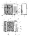
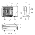
- FIG. 3A is a perspective view of Modification 1 of outdoor unit 100 according to the present embodiment.
- FIG. 3B is a perspective view of the outdoor unit 100 according to Modification 1 shown in FIG. 3A in an exploded state.
- FIG. 3C is a horizontal cross-sectional view of the outdoor unit 100 according to the second modification.
- FIG. 3D is an explanatory diagram in a state where the cover 1D of the outdoor unit 100 according to Modification 2 is removed.
- 3D (a) is a front view of the outdoor unit 100 according to Modification 1
- FIG. 3D (b) is a right side view of the outdoor unit 100 according to Modification 1
- FIG. 3D (c) are the perspective views of the outdoor unit 100 which concerns on the modification 1.
- FIG. In the first modification unlike the present embodiment, the height of the fixed panel 1F does not reach the top panel 1A.
- the front panel 1B has a front notch 1BH formed below the end of the second side panel 1C.
- the second side panel 1C has a side notch 1CH formed under the front side end portion that is the front panel 1B side.
- the fixed panel 1F is provided so as to extend from the bottom panel 1E side to the height positions of the upper ends of the front cutout 1BH and the side cutout 1CH.
- the cover 1D is provided in the front cutout 1BH and the side cutout 1CH.
- a roof panel 1FF is provided.
- the roof panel 1FF is connected to the upper end of the fixed panel 1F, the front cutout 1BH, and the side cutout 1CH, and is disposed on the upper side of the bulb 7.
- the roof panel 1FF can be composed of, for example, a triangular plate member.
- the roof panel 1FF is arranged so that the apex portion of the corner C of the bottom panel 1E comes below the apex.
- the apex of the roof panel 1FF is located at the corner of the right side end of the front panel 1B and the corner of the front side end of the second side panel 1C.
- this vertex has a larger angle than the other two vertices.
- the left side end portion of the front panel 1B and the front side end portion of the second side panel 1C are provided along.
- the front panel 1B and the second side panel 1C are separated from each other at the positions where the front notch 1BH and the side notch 1CH are formed.
- the outdoor unit 100 according to Modification 1 can increase the volume of the machine room R1 and is limited in the outdoor unit 100. There is an effect that it is easy to use space effectively.
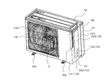
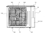
- FIG. 4A is a perspective view of Modification 2 of outdoor unit 100 according to the present embodiment.
- FIG. 4B is a perspective view of the outdoor unit 100 according to Modification 2 shown in FIG. 4A in an exploded state.
- FIG. 4C is a horizontal cross-sectional view of the outdoor unit 100 according to the second modification.
- FIG. 4D is an explanatory diagram in a state where the cover 1D of the outdoor unit 100 according to Modification 2 is removed.
- FIG. 4E is an explanatory diagram of the outdoor unit 100 according to the modified example 2, and is an explanatory diagram in a state where the cover 1D is attached.
- 4D (a) is a front view of the outdoor unit 100 according to Modification 2 and FIG.
- FIG. 4D (b) is a right side view of the outdoor unit 100 according to Modification 2.
- FIG. 4D (c) These are top view of the outdoor unit 100 which concerns on the modification 2.
- FIG. In the modification 2, the 1st protrusion part J is formed in the edge part of the outdoor heat exchanger 2, and it suppresses the enlargement of the outdoor unit 100, increasing the lateral width of the outdoor heat exchanger 2. It is possible.
- the bottom panel 1E includes a first protrusion J that is formed on the peripheral edge 1E1 where the second side panel 1C is provided and protrudes in the horizontal direction.
- This 1st protrusion part J is formed in the part corresponding to the edge part of 2 A of 1st heat exchange parts of the outdoor heat exchanger 2, and protrudes in a horizontal direction.
- the taper surface J1 which goes to the edge part of the 1st protrusion part J toward the part located in the lower side of the valve
- the cover 1D is formed with a terminal block protection portion 1D4 formed so as to cover the attachment portion Q such as a terminal block connected to the electrical component box 6.
- the terminal block protection part 1D4 is formed on the same plane as the drawer part 1D3, and is formed at a position protruding to the right side from the side part 1D2.
- the terminal block protection part 1D4 has a lower end connected to an upper end of the lead part 1D3. Further, the terminal block protection part 1D4 has a lower side end connected to the side part 1D2.
- the cover 1D is formed by integrally forming the front surface portion 1D1, the side surface portion 1D2, the drawer portion 1D3, and the terminal block protection portion 1D4. In the second modification, the cover 1D can protect not only the valve 7 but also the terminal block.
- outdoor unit 100 according to Modification 2 has the following effects. That is, in the outdoor unit 100 according to the modified example 2, the first protrusion J is formed at the end of the outdoor heat exchanger 2, and the lateral width of the outdoor heat exchanger 2 is increased, but the The increase in size can be suppressed.
- the second side panel 1C also has a tapered surface parallel to the tapered surface J1, so that the refrigerant pipe P can be disposed along the side surface. For this reason, it is possible to avoid the refrigerant pipe P from interfering and to prevent the refrigerant pipe P from being damaged.
- FIG. 5A is a front view of Modification 3 of outdoor unit 100 according to the present embodiment.
- FIG. 5B is a horizontal sectional view of the outdoor unit 100 according to Modification 3.
- FIG. 5C is an enlarged view of region B shown in FIG. 5B.
- FIG. 5D is an explanatory diagram in a state where the cover 1D of the outdoor unit 100 according to Modification 3 is removed.
- 5D (a) is a perspective view of the outdoor unit 100 according to the third modification
- FIG. 5D (b) is a top view of the outdoor unit 100 according to the third modification.
- the 2nd protrusion part Z is formed in the arrangement position of the valve
- the bottom panel 1E includes a second protrusion Z that is formed on the peripheral edge 1E1 on the side where the fixed panel 1F is provided and protrudes to the front side in the horizontal direction.
- the valve 7 is disposed on the upper side of the second protrusion Z.
- the front end of the second protrusion Z is provided so as not to protrude from the front end of the leg 1E2. That is, the front end of the second protrusion Z is disposed on the rear side in the front-rear direction of the casing of the outdoor unit 100 with respect to the front end of the leg 1E2.
- the outdoor unit 100 according to Modification 3 has the following effects in addition to the same effects as the outdoor unit 100 according to the present embodiment. That is, in the outdoor unit 100 according to the modified example 3, since the valve 7 is arranged above the second projecting portion Z, the volume of the machine room R1 can be increased correspondingly, and the outdoor unit 100 can be increased accordingly. The limited space inside can be used effectively. Further, the outdoor unit 100 according to the modified example 3 is provided so that the front end of the second projecting portion Z does not protrude from the front end of the leg portion 1E2, so that the transport efficiency of the outdoor unit 100 is not deteriorated. There is an effect that the machine room can be enlarged.
- the outdoor unit 100 according to the modified example 3 has the second protrusion Z formed on the bottom panel 1E, and the fixed panel 1F provided with the valve 7 is disposed at the position where the second protrusion Z is formed. Yes.
- the formation position of the second protrusion Z is a front space of the outdoor unit 100 and is a dead space that forms an air passage. For this reason, even if the outdoor unit 100 in which the 2nd protrusion part Z was formed is installed, it can avoid that it becomes difficult to use the space (a veranda etc.) in which the outdoor unit 100 was installed.
Landscapes
- Engineering & Computer Science (AREA)
- Chemical & Material Sciences (AREA)
- Combustion & Propulsion (AREA)
- Mechanical Engineering (AREA)
- General Engineering & Computer Science (AREA)
- Other Air-Conditioning Systems (AREA)
Abstract
Description
図1は、本実施の形態に係る室外機100を備えた空気調和装置200の模式図である。図1(a)は、空気調和装置200の冷媒回路構成の一例を示し、図1(b)では、室外機100と室内機150とが冷媒配管Pで接続されている様子を示している。なお、本実施の形態では、冷凍サイクル装置が空気調和装置200である場合の例を説明する。
空気調和装置200は、室内機150と室外機100とを有し、これらが冷媒配管Pで接続されて構成されている。室内機150は、冷房運転時に蒸発器として機能し、暖房運転時に凝縮器として機能する室内熱交換器151などを有している。そして、室外機100で生成された冷熱あるいは温熱は、冷媒配管Pを介して室内機150に配送されるようになっている。
室内機150は、たとえば室内などのように空調対象空間に冷房用空気、又は暖房用空気を供給できる位置に配置され、空調対象空間に冷房用空気、又は暖房用空気を供給するものである。室内機150は、空気と冷媒とを熱交換する室内熱交換器151、及び室内熱交換器151に空気を供給する送風機152が搭載されている。
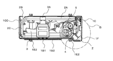
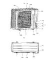
図2Aは、本実施の形態に係る室外機100の斜視図である。図2Bは、本実施の形態に係る室外機100を分解した状態の斜視図である。図2Cは、本実施の形態に係る室外機100の水平断面図である。図2Dは、図2Cに示す領域Bの拡大図である。
室外機100は、冷房運転時に凝縮器として機能し、暖房運転時に蒸発器として機能する室外熱交換器2などを有しているものである。以下の説明では、前面パネル1Bを室外機の前面(正面)と規定し、正面に向かって第1の側面パネル1CCが配置されている側を左側と規定し、正面に向かって第2の側面パネル1Cが配置されている側を右側と規定している。
また、室外機100は、室外機100内の空間を左側と右側に区画する仕切板5、冷媒を圧縮して吐出する圧縮機4、水平断面形状がL字状の室外熱交換器2、室外熱交換器2に外気を供給する送風機3、及び、送風機3を保持するモーターサポート3Aなどが搭載されている。その他に、室外機100には、四方弁8、及び圧縮機4の回転数を制御する制御装置などが設けられた電気品箱6も搭載されている。
さらに、室外機100は、周面パネルの内側に位置するように底面パネル1Eの角部Cに配置され、底面パネル1Eに立設する固定パネル1Fと、固定パネル1Fに固定され、冷媒配管Pが接続されるバルブ7と、バルブ7を覆うように取り付けられるカバー1Dとを備えている。
天面パネル1Aは、室外機100の上面を構成するものである。天面パネル1Aは、室外熱交換器2の上部を覆うように、周面パネルの上端部に設けられたものである。天面パネル1Aは、前側端部及び左側端部が、前面パネル1B及び第1の側面パネル1CCに接触して支持されて設けられ、右側端部が第2の側面パネル1Cに接触して支持されて設けられている。天面パネル1Aは、たとえば金属板などから構成される。
前面パネル1Bは、室外機100の前面の一部を構成するものである。前面パネル1Bは、左側の側端部に第1の側面パネル1CCが設けられ、右側の側端部にカバー1Dが設けられている。また、前面パネル1Bは、右側の側端部にカバー1Dが付設される。なお、本実施の形態において、第1の側面パネル1CCと前面パネル1Bとは連結して一体的に構成されている。
前面パネル1Bは、下端部が底面パネル1Eの周縁部1E1上に設けられており、また、上端部に天面パネル1Aが設けられている。また、前面パネル1Bのうち前面構成部分の右側端部は、第2の側面パネル1Cの前側の側端部に沿うように設けられている。さらに、前面パネル1Bには、たとえば外気吸込口となる円形の開口部1B1が形成されている。なお、ファングリル1B2は、開口部1B1の形成位置に対向するように設けられている。前面パネル1Bは、たとえば樹脂などで構成される。
第2の側面パネル1Cは、室外機100の後面の一部及び右側面を構成するものである。この第2の側面パネル1Cは、水平断面形状が略L字であって底面パネル1Eに鉛直に立設され、圧縮機4の側方及び後側に配置されているものである。第2の側面パネル1Cは、前側端部がカバー1Dの側端部に沿うように設けられ、上端部が天面パネル1Aと接触して設けられ、下端部が底面パネル1Eと接触して設けられている。第2の側面パネル1Cは、たとえばABS樹脂などで構成される。
ファングリル1B2は、室外機100の前面の一部を構成し、ユーザーなどが、送風機3でケガをすることなどを防止するのに利用されるものである。このファングリル1B2は、たとえば縦桟と横桟からなる格子状部材である。
底面パネル1Eは、室外機100の底面の一部を構成するものである。底面パネル1Eは、圧縮機4及び室外熱交換器2などの下側に配置され、圧縮機4及び室外熱交換器2を支持する矩形状部材である。底面パネル1Eの周縁には、鉛直に立設する周縁部1E1が形成されている。すなわち、周縁部1E1は、底面パネル1Eの周縁部に形成されたフランジ状の部分である。底面パネル1Eの上側には、室外熱交換器2、圧縮機4及び仕切板5などが設けられている。底面パネル1Eは、たとえば金属板などから構成される。また、底面パネル1Eの下面側には、室外機100を載置するのに利用される脚部1E2が設けられている。
仕切板5は、圧縮機4及びバルブ7が配置される側と、室外熱交換器2及び送風機3が配置される側とを仕切るように配置されている。すなわち、仕切板5は、圧縮機4が設けられる機械室R1と、室外熱交換器2、送風機3、及びモーターサポート3Aなどが設けられる送風機室R2とを区画するものである。仕切板5は、たとえば、底面パネル1E上に配置される。そして、仕切板5は、前端部が前面パネル1Bに配置され、後端部が室外熱交換器2の端部に固定される。
圧縮機4は、冷媒を吸入し、その冷媒を圧縮して高温・高圧の状態にして吐出するものである。圧縮機4は、冷媒の流れを切り替えて冷房運転及び暖房運転を切り替える四方弁8に配管を介して接続されている。圧縮機4の周囲には、仕切板5、前面パネル1B、及び固定パネル1Fなどが配置されている。なお、圧縮機4の上部には、各種制御などに利用される電気品箱6が設けられている。なお、圧縮機4は、底面パネル1E上に直接載置されている必要はなく、底面パネル1Eに設けた設置台の上に載置されていてもよい。
室外熱交換器2は、送風機3によって室外機100に取り込まれる空気と冷媒との間で熱交換を行わせ、冷房運転時に冷媒を凝縮液化させ、暖房運転時に冷媒を蒸発ガス化させるものである。室外熱交換器2は、たとえば、底面パネル1E上に設けられている。なお、室外熱交換器2は、底面パネル1E上に直接載置されている必要はなく、底面パネル1Eに設けた設置台の上に載置されていてもよい。室外熱交換器2の上部には、モーターサポート3Aが掛けられるようにして設けられている。室外熱交換器2は、たとえば伝熱管を流れる冷媒とフィンを通過する空気との間で熱交換ができるようなフィンアンドチューブ熱交換器で構成される。
室外熱交換器2は、第1の側面パネル1CCから第2の側面パネル1Cに向かう方向に平行に延びる第1の熱交換部2Aと、曲げられた第2の熱交換部2Bと、第1の側面パネル1CCに対向するように設けられた第3の熱交換部2Cとを含むものである。第1の熱交換部2Aと第2の熱交換部2Bとが接続されており、第2の熱交換部2Bと第3の熱交換部2Cとが接続されている。室外熱交換器2の第2の側面パネル1C側の端部には、たとえば、各種配管及び伝熱管に冷媒を分配するヘッダーなどの冷媒流通部材20が配置されている。すなわち、冷媒流通部材20は、第1の熱交換部2Aの端部側に設けられている。なお、第3の熱交換部2Cには、伝熱管が半円状に曲げられたヘアピン2C1が設けられている。
固定パネル1Fは、圧縮機4が配置される側の空間(機械室R1)と、バルブ7が配置される側の空間とを仕切るように構成されているものである。固定パネル1Fは、底面パネル1Eから天面パネル1Aにかけて上下方向に延びるように設けられた平板状部材である。なお、カバー1D及び第2の側面パネル1Cも、底面パネル1Eから天面パネル1Aにかけて上下方向に延びるように設けられている。固定パネル1Fの一方(前側)の側端部は前面パネル1Bの内側面に対向するように位置し、固定パネル1Fの他方(後側)の側端部は第2の側面パネル1Cの前側端部に沿うように設けられている。固定パネル1Fは、前面パネル1Bとの間に鋭角が形成されるように設けられている。
バルブ7は、固定パネル1Fに取り付けられているものである。バルブ7は、細管用バルブ7A及び太管用バルブ7Bから構成されている。バルブ7には、冷媒配管Pが接続されている。バルブ7は、固定パネル1Fの外側面と底面パネル1Eの上面とカバー1Dの内側面との間に形成される閉空間SPに配置されている。このため、仮に、室外機100の筐体の内外を接続する冷媒配管Pの外側に巻かれる断熱カバーに引火しても、炎が機械室R1内へ延焼してしまうことを防ぐことができる。つまり、炎が圧縮機4及び室外熱交換器2などに及ぶことを回避することができるようになっている。
カバー1Dは、底面パネル1Eの周縁部1E1上に配置され、バルブ7を覆うように固定パネル1Fの対向位置に着脱自在に設けられたものである。カバー1Dは、底面パネル1Eの角部Cに対応する位置に取り付けられるものである。カバー1Dは、室外機100の筐体のうちの前面の一部及び右側面の一部を構成する。カバー1Dは、水平断面視形状が、L字状となっている。カバー1Dは、上下方向に延びるように設けられている。カバー1Dは、前面パネル1Bに平行に設けられる前面部1D1と、前面部1D1に直交する側面部1D2と、バルブ7に接続される冷媒配管Pを引き出すのに利用される引出部1D3とを含むものである。カバー1Dは、前面部1D1、側面部1D2及び引出部1D3が一体的に形成されたものである。カバー1Dは、たとえば、樹脂などで構成してもよいし、金属板などで構成してもよい。
側面部1D2は、第2の側面パネル1Cの外表面に沿うように設けられた平板状部材である。側面部1D2は、底面パネル1Eから天面パネル1Aまで延びるように形成された平板状部材である。側面部1D2の後側の側端部には、バルブ7の高さ位置に、引出部1D3が形成されている。
引出部1D3は、側面部1D2よりも右側に突出するように形成されているものである。したがって、カバー1Dの側面は、引出部1D3の形成部分が段差状になっている。仮に、カバー1Dに引出部1D3が形成されていないと、冷媒配管Pの引出は容易であるが、雨水などが室外機100の筐体内に侵入してしまう。しかし、カバー1Dには、側面部1D2よりも突出している引出部1D3が形成されているため、冷媒配管Pとの干渉を回避しながらも、雨水などが室外機100の筐体内に侵入することを抑制することができるようになっている。
本実施の形態に係る室外機100は、周面パネル(前面パネル1B及び第2の側面パネル1C)の内側に位置するように底面パネル1Eの角部Cに配置され、底面パネル1Eに立設する固定パネル1Fと、固定パネル1Fに固定され、冷媒配管Pが接続されるバルブ7とを備えたものである。このため、バルブ7が室外機100の底面パネル1Eの周縁部1E1よりも内側に位置することになる。つまり、室外機100では、従来の室外機のようにバルブが室外機の筐体の外側から飛び出してしまうようなことを回避することができる。したがって、本実施の形態に係る室外機100は、サイズを小さくすることができる。
図3Aは、本実施の形態に係る室外機100の変形例1の斜視図である。図3Bは、図3Aに示す変形例1に係る室外機100を分解した状態の斜視図である。図3Cは、変形例2に係る室外機100の水平断面図である。図3Dは、変形例2に係る室外機100のカバー1Dを外した状態における説明図である。なお、図3D(a)は、変形例1に係る室外機100の正面図であり、図3D(b)は、変形例1に係る室外機100の右側面図であり、図3D(c)は、変形例1に係る室外機100の斜視図である。変形例1では、本実施の形態とは異なり、固定パネル1Fの高さが天面パネル1Aまで至っていない。
変形例1に係る室外機100は、本実施の形態に係る室外機100と同様の効果を有することに加えて、機械室R1の容積を大きくすることができ、室外機100内の限られたスペースを有効活用しやすいという効果がある。
図4Aは、本実施の形態に係る室外機100の変形例2の斜視図である。図4Bは、図4Aに示す変形例2に係る室外機100を分解した状態の斜視図である。図4Cは、変形例2に係る室外機100の水平断面図である。図4Dは、変形例2に係る室外機100のカバー1Dを外した状態における説明図である。図4Eは、変形例2に係る室外機100の説明図であって、カバー1Dを取り付けている状態における説明図である。なお、図4D(a)は、変形例2に係る室外機100の正面図であり、図4D(b)は、変形例2に係る室外機100の右側面図であり、図4D(c)は、変形例2に係る室外機100の上面視図である。変形例2では、室外熱交換器2の端部に第1の突出部Jが形成されており、室外熱交換器2の横幅を大きくしながらも、室外機100の大型化を抑制することができるものとなっている。
変形例2に係る室外機100は、本実施の形態に係る室外機100と同様の効果を有することに加えて、次の効果を有する。すなわち、変形例2に係る室外機100では、室外熱交換器2の端部に第1の突出部Jが形成されており、室外熱交換器2の横幅を大きくしながらも、室外機100の大型化を抑制することができるものとなっている。
また、変形例2に係る室外機100では、第2の側面パネル1Cにもテーパー面J1に平行なテーパー面が形成されているため、冷媒配管Pを側面に沿わせて配置することができる。このため、冷媒配管Pが邪魔になることを回避するとともに、冷媒配管Pが破損などをすることを抑制することができる。
図5Aは、本実施の形態に係る室外機100の変形例3の正面図である。図5Bは、変形例3に係る室外機100の水平断面図である。図5Cは、図5Bに示す領域Bの拡大図である。図5Dは、変形例3に係る室外機100のカバー1Dを外した状態における説明図である。なお、図5D(a)は、変形例3に係る室外機100の斜視図であり、図5D(b)は、変形例3に係る室外機100の上面視図である。変形例3では、バルブ7の配置位置に第2の突出部Zを形成して、機械室R1の容積を拡大している。
変形例3に係る室外機100は、本実施の形態に係る室外機100と同様の効果を有することに加えて、次の効果を有する。すなわち、変形例3に係る室外機100では、第2の突出部Zの上側にバルブ7が配置されるようにしたので、その分、機械室R1の容積を増大させることができ、室外機100内の限られたスペースを有効活用することができる。
また、変形例3に係る室外機100は、第2の突出部Zの前端が、脚部1E2の前端よりも突出しないように設けられているので、室外機100の輸送効率を悪化させずに、機械室を拡大することができるという効果がある。
さらに、変形例3に係る室外機100は、底面パネル1Eに第2の突出部Zを形成し、その第2の突出部Zの形成位置にバルブ7が設けられた固定パネル1Fが配置されている。室外機100を設置したときにおいて、第2の突出部Zの形成位置は、室外機100の前面部にあたり、風路を形成するデッドスペースとなっている。このため、第2の突出部Zを形成した室外機100を設置しても、室外機100が設置されたスペース(ベランダなど)の利用がしにくくなることを回避することができる。
Claims (9)
- 室内機との間で冷媒を循環させるのに利用される冷媒配管が接続され、圧縮機及び室外熱交換器が搭載された室外機であって、
前記圧縮機及び前記室外熱交換器の下側に配置され、前記圧縮機及び前記室外熱交換器を支持する矩形状の底面パネルと、
前記底面パネルの周縁部上に配置され、前記底面パネルに立設する周面パネルと、
前記周面パネルの内側に位置するように前記底面パネルの角部に配置され、前記底面パネルに立設する固定パネルと、
前記固定パネルに固定され、前記冷媒配管が接続されるバルブと、
を備えた
室外機。 - 前記室外熱交換器に付設され、前記室外機に空気を供給する送風機と、
前記室外熱交換器及び前記送風機が配置される側と前記圧縮機及び前記バルブが配置される側とを仕切るように配置された仕切板とをさらに備え、
前記固定パネルは、
前記圧縮機が配置される側の空間と、前記バルブが配置される側の空間とを仕切るように構成されている
請求項1に記載の室外機。 - 前記底面パネルの周縁部上に配置され、前記バルブを覆うように前記固定パネルの対向位置に設けられたカバーをさらに備え、
前記カバーは、
前記バルブに接続される前記冷媒配管を引き出すのに利用される引出部が形成されている
請求項1又は2に記載の室外機。 - 前記周面パネルは、
前記底面パネルの周縁部に設けられ、前記カバーが付設されている側面パネルと、
側端部に前記側面パネルが設けられるとともに前記カバーが付設され、前記底面パネルの周縁部に設けられた前面パネルとを含む
請求項3に記載の室外機。 - 前記室外熱交換器の上部を覆うように、前記周面パネルの上端部に設けられた天面パネルをさらに備え、
前記固定パネル、前記カバー及び前記側面パネルのそれぞれは、
前記底面パネルから前記天面パネルにかけて延びるように設けられている
請求項4に記載の室外機。 - 前記前面パネルは、
前記側面パネル側の端部の下側に前面切欠部が形成され、
前記側面パネルは、
前記側端部の下側に側面切欠部が形成され、
前記固定パネルは、
前記底面パネル側から前記前面切欠部及び前記側面切欠部の上端の高さ位置まで延びるように設けられ、
前記カバーは、
前記前面切欠部及び前記側面切欠部に設けられている
請求項4に記載の室外機。 - 前記固定パネルの上端部、前記前面切欠部及び前記側面切欠部に接続され、前記バルブの上側に配置された屋根パネルをさらに備えた
請求項6に記載の室外機。 - 前記室外熱交換器の端部は、
前記側面パネルの一方の側端部に対向するように設けられ、
前記底面パネルは、
前記室外熱交換器の端部に対応する部分に形成され、水平方向に突出する第1の突出部を含み、
前記第1の突出部の縁部は、
前記底面パネルのうち前記バルブの下側に位置する部分に向かうテーパー面が形成され、
前記側面パネルは、
前記第1の突出部の縁部に沿うように形成されている
請求項4~7のいずれか一項に記載の室外機。 - 前記底面パネルは、
前記固定パネルが設けられている側の前記周縁部に形成され、水平方向の前側に突出する第2の突出部を含み、
前記バルブは、
前記第2の突出部の上側に配置されている
請求項4~8のいずれか一項に記載の室外機。
Priority Applications (6)
| Application Number | Priority Date | Filing Date | Title |
|---|---|---|---|
| EP14901009.2A EP3059509B1 (en) | 2014-12-26 | 2014-12-26 | Outdoor unit |
| JP2016565795A JP6227166B2 (ja) | 2014-12-26 | 2014-12-26 | 室外機 |
| US15/520,597 US10132512B2 (en) | 2014-12-26 | 2014-12-26 | Outdoor unit |
| PCT/JP2014/084489 WO2016103441A1 (ja) | 2014-12-26 | 2014-12-26 | 室外機 |
| CN201480083245.3A CN107076433B (zh) | 2014-12-26 | 2014-12-26 | 室外机 |
| CN201520788248.9U CN205174613U (zh) | 2014-12-26 | 2015-10-12 | 室外机 |
Applications Claiming Priority (1)
| Application Number | Priority Date | Filing Date | Title |
|---|---|---|---|
| PCT/JP2014/084489 WO2016103441A1 (ja) | 2014-12-26 | 2014-12-26 | 室外機 |
Publications (1)
| Publication Number | Publication Date |
|---|---|
| WO2016103441A1 true WO2016103441A1 (ja) | 2016-06-30 |
Family
ID=55738601
Family Applications (1)
| Application Number | Title | Priority Date | Filing Date |
|---|---|---|---|
| PCT/JP2014/084489 Ceased WO2016103441A1 (ja) | 2014-12-26 | 2014-12-26 | 室外機 |
Country Status (5)
| Country | Link |
|---|---|
| US (1) | US10132512B2 (ja) |
| EP (1) | EP3059509B1 (ja) |
| JP (1) | JP6227166B2 (ja) |
| CN (2) | CN107076433B (ja) |
| WO (1) | WO2016103441A1 (ja) |
Cited By (1)
| Publication number | Priority date | Publication date | Assignee | Title |
|---|---|---|---|---|
| CN111928349A (zh) * | 2020-08-24 | 2020-11-13 | 武汉宏海科技股份有限公司 | 一种新型空调外机前面板 |
Families Citing this family (9)
| Publication number | Priority date | Publication date | Assignee | Title |
|---|---|---|---|---|
| KR101900484B1 (ko) | 2015-01-23 | 2018-09-20 | 삼성전자주식회사 | 공기 조화기 |
| CN109028353B (zh) * | 2018-07-18 | 2020-05-22 | 广东美的制冷设备有限公司 | 空调室外机和空调器 |
| CN109163387B (zh) * | 2018-10-23 | 2024-09-06 | 珠海格力电器股份有限公司 | 一种用于空调室外机的气流反向结构及空调室外机 |
| JP2020128833A (ja) * | 2019-02-08 | 2020-08-27 | パナソニックIpマネジメント株式会社 | ヒートポンプシステム |
| USD957606S1 (en) | 2020-01-15 | 2022-07-12 | Lendell Martin, Sr. | Base for air system |
| US11976828B2 (en) * | 2020-03-30 | 2024-05-07 | Mitsubishi Electric Corporation | Outdoor unit of air-conditioning apparatus |
| CN115917217B (zh) * | 2020-09-08 | 2026-03-17 | 三菱电机株式会社 | 室外机 |
| CN112880127B (zh) * | 2021-01-28 | 2022-06-21 | 广东美的制冷设备有限公司 | 一种故障检测方法、装置、设备及存储介质 |
| EP4459196A1 (en) * | 2023-05-05 | 2024-11-06 | BDR Thermea Group B.V. | Base unit for a heat pump |
Citations (9)
| Publication number | Priority date | Publication date | Assignee | Title |
|---|---|---|---|---|
| US4153310A (en) * | 1978-06-26 | 1979-05-08 | Westinghouse Electric Corp. | Air conditioning outdoor section cabinet construction |
| JPS6425635U (ja) * | 1987-08-07 | 1989-02-13 | ||
| JPH05133571A (ja) | 1991-11-15 | 1993-05-28 | Matsushita Electric Ind Co Ltd | 空気調和機の室外ユニツト |
| JPH05296496A (ja) * | 1992-04-22 | 1993-11-09 | Mitsubishi Electric Corp | 空気調和機の室外ユニット |
| JPH08219495A (ja) * | 1995-02-08 | 1996-08-30 | Fujitsu General Ltd | 空気調和機の室外機 |
| JP2003254563A (ja) * | 2001-12-27 | 2003-09-10 | Sanyo Electric Co Ltd | 空気調和装置 |
| US20050204767A1 (en) * | 2002-05-24 | 2005-09-22 | Norrell Billy W | Base pan and cabinet for an air conditioner |
| JP2007120900A (ja) * | 2005-10-31 | 2007-05-17 | Daikin Ind Ltd | 閉鎖弁サポート部材及びそれを備えた空気調和装置の室外ユニット |
| US20130219942A1 (en) * | 2012-02-23 | 2013-08-29 | Rheem Manufacturing Company | Air Conditioner and Heat Pump Condensing Unit Chassis with Enhanced Serviceability Access |
Family Cites Families (4)
| Publication number | Priority date | Publication date | Assignee | Title |
|---|---|---|---|---|
| JP3523823B2 (ja) * | 2000-02-29 | 2004-04-26 | 東芝キヤリア株式会社 | 空気調和機の室外ユニット |
| JP2008020132A (ja) * | 2006-07-13 | 2008-01-31 | Daikin Ind Ltd | 空気調和機の室外機 |
| IT1400737B1 (it) * | 2009-05-20 | 2013-07-02 | Sanyo Electric Co | Unita' esterna per lo scambio di calore, particolarmente in scambiatori di calore e simili. |
| JP6099925B2 (ja) * | 2012-10-04 | 2017-03-22 | 三菱重工業株式会社 | 空気調和機の室外ユニット |
-
2014
- 2014-12-26 CN CN201480083245.3A patent/CN107076433B/zh not_active Expired - Fee Related
- 2014-12-26 US US15/520,597 patent/US10132512B2/en not_active Expired - Fee Related
- 2014-12-26 JP JP2016565795A patent/JP6227166B2/ja not_active Expired - Fee Related
- 2014-12-26 WO PCT/JP2014/084489 patent/WO2016103441A1/ja not_active Ceased
- 2014-12-26 EP EP14901009.2A patent/EP3059509B1/en not_active Not-in-force
-
2015
- 2015-10-12 CN CN201520788248.9U patent/CN205174613U/zh not_active Expired - Fee Related
Patent Citations (9)
| Publication number | Priority date | Publication date | Assignee | Title |
|---|---|---|---|---|
| US4153310A (en) * | 1978-06-26 | 1979-05-08 | Westinghouse Electric Corp. | Air conditioning outdoor section cabinet construction |
| JPS6425635U (ja) * | 1987-08-07 | 1989-02-13 | ||
| JPH05133571A (ja) | 1991-11-15 | 1993-05-28 | Matsushita Electric Ind Co Ltd | 空気調和機の室外ユニツト |
| JPH05296496A (ja) * | 1992-04-22 | 1993-11-09 | Mitsubishi Electric Corp | 空気調和機の室外ユニット |
| JPH08219495A (ja) * | 1995-02-08 | 1996-08-30 | Fujitsu General Ltd | 空気調和機の室外機 |
| JP2003254563A (ja) * | 2001-12-27 | 2003-09-10 | Sanyo Electric Co Ltd | 空気調和装置 |
| US20050204767A1 (en) * | 2002-05-24 | 2005-09-22 | Norrell Billy W | Base pan and cabinet for an air conditioner |
| JP2007120900A (ja) * | 2005-10-31 | 2007-05-17 | Daikin Ind Ltd | 閉鎖弁サポート部材及びそれを備えた空気調和装置の室外ユニット |
| US20130219942A1 (en) * | 2012-02-23 | 2013-08-29 | Rheem Manufacturing Company | Air Conditioner and Heat Pump Condensing Unit Chassis with Enhanced Serviceability Access |
Non-Patent Citations (1)
| Title |
|---|
| See also references of EP3059509A4 |
Cited By (1)
| Publication number | Priority date | Publication date | Assignee | Title |
|---|---|---|---|---|
| CN111928349A (zh) * | 2020-08-24 | 2020-11-13 | 武汉宏海科技股份有限公司 | 一种新型空调外机前面板 |
Also Published As
| Publication number | Publication date |
|---|---|
| EP3059509A1 (en) | 2016-08-24 |
| EP3059509B1 (en) | 2019-05-08 |
| CN107076433A (zh) | 2017-08-18 |
| US10132512B2 (en) | 2018-11-20 |
| US20170314793A1 (en) | 2017-11-02 |
| CN107076433B (zh) | 2019-08-27 |
| JP6227166B2 (ja) | 2017-11-08 |
| JPWO2016103441A1 (ja) | 2017-04-27 |
| CN205174613U (zh) | 2016-04-20 |
| EP3059509A4 (en) | 2016-12-28 |
Similar Documents
| Publication | Publication Date | Title |
|---|---|---|
| JP6227166B2 (ja) | 室外機 | |
| JP5218629B2 (ja) | ヒータ及びそれを備えた冷凍装置の室外ユニット | |
| JP6305619B2 (ja) | 室外機 | |
| EP2835587B1 (en) | Heat exchanger for air-conditioning device and air-conditioning device | |
| US20210310690A1 (en) | Kitchen Air Conditioning System | |
| WO2013046724A1 (ja) | 室外機及び冷凍装置 | |
| JP6732110B2 (ja) | 室外機、空気調和機、及び、室外機の製造方法 | |
| US12078427B2 (en) | Heat exchanger and air conditioner having the same | |
| JP6227167B2 (ja) | 室外機 | |
| JP7086269B2 (ja) | 室内機 | |
| CN205957431U (zh) | 室内机以及制冷循环装置 | |
| JP7544108B2 (ja) | ヒートポンプサイクル装置の室外機、及び、ヒートポンプサイクル装置 | |
| JP7325600B2 (ja) | 室外機およびそれを備えた空気調和装置 | |
| KR200396503Y1 (ko) | 천정용 에어컨 | |
| JP2013200105A (ja) | 空気調和機 |
Legal Events
| Date | Code | Title | Description |
|---|---|---|---|
| REEP | Request for entry into the european phase |
Ref document number: 2014901009 Country of ref document: EP |
|
| WWE | Wipo information: entry into national phase |
Ref document number: 2014901009 Country of ref document: EP |
|
| 121 | Ep: the epo has been informed by wipo that ep was designated in this application |
Ref document number: 14901009 Country of ref document: EP Kind code of ref document: A1 |
|
| ENP | Entry into the national phase |
Ref document number: 2016565795 Country of ref document: JP Kind code of ref document: A |
|
| WWE | Wipo information: entry into national phase |
Ref document number: 15520597 Country of ref document: US |
|
| NENP | Non-entry into the national phase |
Ref country code: DE |