WO2016103700A1 - レンズ駆動装置、カメラモジュール、及びカメラ搭載装置 - Google Patents
レンズ駆動装置、カメラモジュール、及びカメラ搭載装置 Download PDFInfo
- Publication number
- WO2016103700A1 WO2016103700A1 PCT/JP2015/006426 JP2015006426W WO2016103700A1 WO 2016103700 A1 WO2016103700 A1 WO 2016103700A1 JP 2015006426 W JP2015006426 W JP 2015006426W WO 2016103700 A1 WO2016103700 A1 WO 2016103700A1
- Authority
- WO
- WIPO (PCT)
- Prior art keywords
- unit
- autofocus
- lens
- magnet
- movable
- Prior art date
- Legal status (The legal status is an assumption and is not a legal conclusion. Google has not performed a legal analysis and makes no representation as to the accuracy of the status listed.)
- Ceased
Links
Images



Classifications
-
- G—PHYSICS
- G03—PHOTOGRAPHY; CINEMATOGRAPHY; ANALOGOUS TECHNIQUES USING WAVES OTHER THAN OPTICAL WAVES; ELECTROGRAPHY; HOLOGRAPHY
- G03B—APPARATUS OR ARRANGEMENTS FOR TAKING PHOTOGRAPHS OR FOR PROJECTING OR VIEWING THEM; APPARATUS OR ARRANGEMENTS EMPLOYING ANALOGOUS TECHNIQUES USING WAVES OTHER THAN OPTICAL WAVES; ACCESSORIES THEREFOR
- G03B5/00—Adjustment of optical system relative to image or object surface other than for focusing
- G03B5/02—Lateral adjustment of lens
-
- G—PHYSICS
- G02—OPTICS
- G02B—OPTICAL ELEMENTS, SYSTEMS OR APPARATUS
- G02B7/00—Mountings, adjusting means, or light-tight connections, for optical elements
- G02B7/02—Mountings, adjusting means, or light-tight connections, for optical elements for lenses
- G02B7/04—Mountings, adjusting means, or light-tight connections, for optical elements for lenses with mechanism for focusing or varying magnification
-
- G—PHYSICS
- G02—OPTICS
- G02B—OPTICAL ELEMENTS, SYSTEMS OR APPARATUS
- G02B27/00—Optical systems or apparatus not provided for by any of the groups G02B1/00 - G02B26/00, G02B30/00
- G02B27/64—Imaging systems using optical elements for stabilisation of the lateral and angular position of the image
- G02B27/646—Imaging systems using optical elements for stabilisation of the lateral and angular position of the image compensating for small deviations, e.g. due to vibration or shake
-
- G—PHYSICS
- G02—OPTICS
- G02B—OPTICAL ELEMENTS, SYSTEMS OR APPARATUS
- G02B7/00—Mountings, adjusting means, or light-tight connections, for optical elements
- G02B7/02—Mountings, adjusting means, or light-tight connections, for optical elements for lenses
-
- G—PHYSICS
- G02—OPTICS
- G02B—OPTICAL ELEMENTS, SYSTEMS OR APPARATUS
- G02B7/00—Mountings, adjusting means, or light-tight connections, for optical elements
- G02B7/02—Mountings, adjusting means, or light-tight connections, for optical elements for lenses
- G02B7/04—Mountings, adjusting means, or light-tight connections, for optical elements for lenses with mechanism for focusing or varying magnification
- G02B7/09—Mountings, adjusting means, or light-tight connections, for optical elements for lenses with mechanism for focusing or varying magnification adapted for automatic focusing or varying magnification
-
- G—PHYSICS
- G03—PHOTOGRAPHY; CINEMATOGRAPHY; ANALOGOUS TECHNIQUES USING WAVES OTHER THAN OPTICAL WAVES; ELECTROGRAPHY; HOLOGRAPHY
- G03B—APPARATUS OR ARRANGEMENTS FOR TAKING PHOTOGRAPHS OR FOR PROJECTING OR VIEWING THEM; APPARATUS OR ARRANGEMENTS EMPLOYING ANALOGOUS TECHNIQUES USING WAVES OTHER THAN OPTICAL WAVES; ACCESSORIES THEREFOR
- G03B13/00—Viewfinders; Focusing aids for cameras; Means for focusing for cameras; Autofocus systems for cameras
- G03B13/32—Means for focusing
- G03B13/34—Power focusing
- G03B13/36—Autofocus systems
-
- G—PHYSICS
- G03—PHOTOGRAPHY; CINEMATOGRAPHY; ANALOGOUS TECHNIQUES USING WAVES OTHER THAN OPTICAL WAVES; ELECTROGRAPHY; HOLOGRAPHY
- G03B—APPARATUS OR ARRANGEMENTS FOR TAKING PHOTOGRAPHS OR FOR PROJECTING OR VIEWING THEM; APPARATUS OR ARRANGEMENTS EMPLOYING ANALOGOUS TECHNIQUES USING WAVES OTHER THAN OPTICAL WAVES; ACCESSORIES THEREFOR
- G03B30/00—Camera modules comprising integrated lens units and imaging units, specially adapted for being embedded in other devices, e.g. mobile phones or vehicles
-
- H—ELECTRICITY
- H04—ELECTRIC COMMUNICATION TECHNIQUE
- H04N—PICTORIAL COMMUNICATION, e.g. TELEVISION
- H04N23/00—Cameras or camera modules comprising electronic image sensors; Control thereof
-
- H—ELECTRICITY
- H04—ELECTRIC COMMUNICATION TECHNIQUE
- H04N—PICTORIAL COMMUNICATION, e.g. TELEVISION
- H04N23/00—Cameras or camera modules comprising electronic image sensors; Control thereof
- H04N23/50—Constructional details
- H04N23/55—Optical parts specially adapted for electronic image sensors; Mounting thereof
-
- H—ELECTRICITY
- H04—ELECTRIC COMMUNICATION TECHNIQUE
- H04N—PICTORIAL COMMUNICATION, e.g. TELEVISION
- H04N23/00—Cameras or camera modules comprising electronic image sensors; Control thereof
- H04N23/60—Control of cameras or camera modules
-
- H—ELECTRICITY
- H04—ELECTRIC COMMUNICATION TECHNIQUE
- H04N—PICTORIAL COMMUNICATION, e.g. TELEVISION
- H04N23/00—Cameras or camera modules comprising electronic image sensors; Control thereof
- H04N23/60—Control of cameras or camera modules
- H04N23/68—Control of cameras or camera modules for stable pick-up of the scene, e.g. compensating for camera body vibrations
- H04N23/682—Vibration or motion blur correction
-
- G—PHYSICS
- G03—PHOTOGRAPHY; CINEMATOGRAPHY; ANALOGOUS TECHNIQUES USING WAVES OTHER THAN OPTICAL WAVES; ELECTROGRAPHY; HOLOGRAPHY
- G03B—APPARATUS OR ARRANGEMENTS FOR TAKING PHOTOGRAPHS OR FOR PROJECTING OR VIEWING THEM; APPARATUS OR ARRANGEMENTS EMPLOYING ANALOGOUS TECHNIQUES USING WAVES OTHER THAN OPTICAL WAVES; ACCESSORIES THEREFOR
- G03B2205/00—Adjustment of optical system relative to image or object surface other than for focusing
- G03B2205/0007—Movement of one or more optical elements for control of motion blur
-
- G—PHYSICS
- G03—PHOTOGRAPHY; CINEMATOGRAPHY; ANALOGOUS TECHNIQUES USING WAVES OTHER THAN OPTICAL WAVES; ELECTROGRAPHY; HOLOGRAPHY
- G03B—APPARATUS OR ARRANGEMENTS FOR TAKING PHOTOGRAPHS OR FOR PROJECTING OR VIEWING THEM; APPARATUS OR ARRANGEMENTS EMPLOYING ANALOGOUS TECHNIQUES USING WAVES OTHER THAN OPTICAL WAVES; ACCESSORIES THEREFOR
- G03B2205/00—Adjustment of optical system relative to image or object surface other than for focusing
- G03B2205/0053—Driving means for the movement of one or more optical element
- G03B2205/0069—Driving means for the movement of one or more optical element using electromagnetic actuators, e.g. voice coils
Definitions
- the present invention relates to a lens driving device for autofocus and shake correction, a camera module having an autofocus function and a shake correction function, and a camera mounting device.
- a small camera module is mounted on a mobile terminal such as a smartphone.
- an autofocus function (AF: Auto Focus) that automatically performs focusing when shooting a subject and vibration (vibration) that occurs during shooting are optically detected.
- a lens driving device having a shake correction function (hereinafter referred to as “OIS function”, hereinafter referred to as “OIS function”) that corrects and reduces image distortion is applied (for example, Patent Documents 1 and 2).
- the lens driving device for autofocus and shake correction includes an autofocus driving unit (hereinafter referred to as “AF driving unit”) for moving the lens unit in the optical axis direction, and the lens unit orthogonal to the optical axis direction. And a shake correction drive unit (hereinafter referred to as “OIS drive unit”) for swinging in a plane.
- AF driving unit autofocus driving unit
- OIS drive unit shake correction drive unit
- the AF drive unit includes, for example, an autofocus coil unit (hereinafter referred to as “AF coil unit”) disposed around the lens unit, and an auto unit disposed in a radial direction away from the AF coil unit. And a focusing magnet section (hereinafter referred to as “AF magnet section”).
- AF magnet section a focusing magnet section
- AF fixing unit an autofocus fixing unit including the AF magnet unit. Focusing is automatically performed by moving an autofocus movable part (hereinafter referred to as “AF movable part”) including the AF coil part in the optical axis direction.
- the lens position (most light receiving side) when focusing on the subject at the shortest shooting distance is called the “macro position”, and the lens position (most imaging side) when focusing on the subject at infinity. Position) is called “infinite position”. That is, the range from the macro position to the infinity position is the movable range of the AF movable part.
- the OIS drive unit is arranged, for example, at a distance from the shake correction magnet unit (hereinafter referred to as “OIS magnet unit”) disposed in the AF drive unit and in the optical axis direction with respect to the OIS magnet unit. And a shake correction coil portion (hereinafter referred to as “OIS coil portion”).
- the shake correction movable part (hereinafter referred to as “OIS movable part”) including the AF drive part and the OIS magnet part is hereinafter referred to as “OIS movable part” by the support member.
- the shake correction is performed by swinging the OIS movable portion in a plane orthogonal to the optical axis direction by using the driving force of the voice coil motor constituted by the OIS magnet portion and the OIS coil portion.
- FIG. 1 is a diagram showing a displacement width of a lens portion in a conventional lens driving device.
- FIG. 1A shows a neutral state (when no power is supplied), and
- FIG. 1B shows a state when it is dropped.
- the OIS magnet section is also used as the AF magnet section.
- the AF movable unit 11 in which the lens unit is arranged includes a lens holder 111 and an AF coil unit 112, and the AF fixed unit 12 includes a magnet holder 121 and a magnet unit 122 (for AF). Magnet part).
- the OIS movable unit 10 includes an AF drive unit (AF movable unit 11 and AF fixed unit 12), and is separated from the OIS fixed unit 20 including the OIS coil unit (not shown) toward the light receiving side in the optical axis direction. Supported by
- the AF movable unit 11 moves to the optical axis direction imaging side or the optical axis direction light receiving side to focus.
- the AF movable portion 11 is movable by L1 toward the optical axis direction imaging side (hereinafter referred to as “lower movable range L1”).
- the OIS movable unit 10 is separated from the OIS fixed unit 20 by L2 in order to swing in a plane orthogonal to the optical axis direction (hereinafter referred to as “magnet gap L2”).
- the lens unit when receiving an impact such as dropping, the lens unit is displaced by a movable distance (L1 + L2) of the AF movable unit 11 to the optical axis direction imaging side at the maximum. If the distance L3 between the lens unit and the imaging unit is larger than the maximum displacement (L1 + L2) of the lens unit, the lens unit collides with the imaging unit even if the lens unit is displaced to the optical axis direction imaging side due to an impact such as dropping. None do.
- the lower movable range L1 and the magnet gap L2 of the AF movable portion 11 are designed so that the performance required for the lens driving device is realized.
- the design value of L1 is set to 150 ⁇ m.
- the design value of L2 is set to 90 ⁇ m.
- the displacement width of the lens portion is 240 ⁇ 76 ⁇ m in consideration of the tolerance (root mean square, RMS).
- the separation distance L3 between the lens unit and the imaging unit may be set to 316 ⁇ m or more.
- the distance L3 between the lens unit and the imaging unit is often limited.
- the distance between the lens unit and the imaging unit becomes closer to maintain the module height.
- the allowable displacement range of the lens unit is limited to 265 ⁇ m (the separation distance L3- ⁇ between the lens unit and the imaging unit)
- the above-described design does not necessarily satisfy the requirement.
- the lens unit and the imaging unit collide when subjected to an impact such as a drop, which may cause damage to the IR filter provided on the surface of the imaging device, and lack reliability. . In this way, it is difficult to satisfy the requirements in consideration of mounting tolerances without impairing the reduction in height.
- An object of the present invention is to provide a lens driving device capable of improving reliability without impairing a reduction in height, a camera module including the lens driving device, and a camera mounting device.
- the lens driving device includes an autofocus coil unit disposed around the lens unit, and an autofocus magnet unit disposed radially away from the autofocus coil unit. And using the driving force of a voice coil motor composed of the autofocus coil section and the autofocus magnet section, the autofocus fixing section including the autofocus magnet section is used for the autofocus.
- An autofocus drive unit that automatically focuses by moving the autofocus movable unit including the coil unit in the optical axis direction; and A shake correction magnet unit disposed in the autofocus drive unit, and a shake correction coil unit that is spaced apart from the shake correction magnet unit in the optical axis direction.
- a shake correction movable part including the shake correction magnet part with respect to a shake correction fixed part including the shake correction coil part is provided.
- a shake correction drive unit that performs shake correction by swinging the part in a plane perpendicular to the optical axis direction;
- a sub-stopper that is interposed between the autofocus movable part and the shake correction fixing part and restricts the movable distance of the autofocus movable part toward the image forming side in the optical axis direction within the allowable displacement range of the lens part. And a section.
- a camera module includes the lens driving device described above, A lens unit mounted on the autofocus movable unit; An imaging unit that captures a subject image formed by the lens unit.
- the camera mounting device is a camera mounting device that is an information device or a transport device, The camera module is provided.
- the displacement of the lens portion can be easily within the allowable displacement range without impairing the reduction in height. Therefore, the reliability of the lens driving device is remarkably improved.
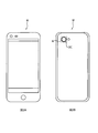
- FIG. 2 is a diagram showing a smartphone M equipped with a camera module A according to an embodiment of the present invention.
- 2A is a front view of the smartphone M
- FIG. 2B is a rear view of the smartphone M.
- the smartphone M is equipped with a camera module A as a rear camera OC, for example.
- the camera module A has an autofocus function and a shake correction function, automatically performs focusing when shooting a subject, and optically corrects shake (vibration) generated during shooting to produce an image free from image blur. You can shoot.
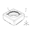
- FIG. 3 is an external perspective view of the camera module A.
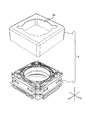
- FIG. FIG. 4 is an exploded perspective view of the camera module A.
- the present embodiment will be described using an orthogonal coordinate system (X, Y, Z).
- a common orthogonal coordinate system (X, Y, Z) is also used.
- the camera module A is mounted so that the X direction is the up / down direction (or left / right direction), the Y direction is the left / right direction (or up / down direction), and the Z direction is the front / rear direction when shooting is actually performed with the smartphone M.
- the Z direction is the optical axis direction
- the upper side in the figure is the optical axis direction light receiving side (also referred to as “macro position side”)
- the lower side is the optical axis direction imaging side (also referred to as “infinity position side”).
- the camera module A includes a lens unit (not shown) in which a lens is accommodated in a cylindrical lens barrel, a lens driving device 1 for AF and OIS, and an imaging unit that captures a subject image formed by the lens unit ( (Not shown), and a shield cover 2 and the like covering the whole.
- the shield cover 2 is a square-shaped covered quadrangular cylinder in a plan view seen from the optical axis direction, and has a circular opening 2a on the upper surface. A lens portion (not shown) faces the outside through the opening 2a.
- the shield cover 2 is fixed to the base member 23 (see FIG. 7) of the OIS fixing unit 20 of the lens driving device 1.
- the shield cover 2 has conductivity and is electrically connected to a ground terminal (not shown) of the OIS fixing unit 20 and grounded.
- the imaging unit has an imaging element (not shown) and is arranged on the optical axis direction imaging side of the lens driving device 1.
- the image sensor (not shown) is configured by, for example, a charge-coupled device (CCD) type image sensor, a complementary metal oxide semiconductor (CMOS) type image sensor, or the like.
- An image sensor (not shown) captures a subject image formed by a lens unit (not shown).
- An IR filter (not shown) is disposed on the light receiving side in the optical axis direction of the image sensor (not shown).
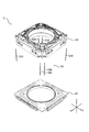
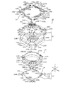
- FIG. 5 is an exploded perspective view of the lens driving device 1.
- the lens driving device 1 includes an OIS movable unit 10, an OIS fixed unit 20, a support member 30, and the like.
- the OIS movable portion 10 has an OIS magnet portion that constitutes an OIS voice coil motor, and is a portion that swings in the XY plane during shake correction.
- the OIS fixing portion 20 is a portion having an OIS coil portion.
- the moving magnet method is employed in the lens driving unit for OIS of the lens driving device 1.
- the OIS movable unit 10 includes an AF drive unit (AF movable unit 11 and AF fixed unit 12, see FIG. 6).
- the OIS movable unit 10 is arranged away from the OIS fixed unit 20 on the light receiving side in the optical axis direction, and is connected to the OIS fixed unit 20 by the support member 30.
- the support member 30 includes six suspension wires extending along the Z direction (hereinafter referred to as “suspension wire 30”).
- One end (upper end) of the suspension wire 30 is fixed to the OIS movable portion 10 (upper elastic support portion 13, see FIG. 6), and the other end (lower end) is fixed to the OIS fixing portion 20 (see the coil substrate 21, FIG. 7).
- the OIS movable unit 10 is supported by the suspension wire 30 so as to be swingable in the XY plane.
- the suspension wires 31A and 31B are used as signal paths of the hall element 161 (see FIG. 6) (signal suspension wires), and the suspension wires 32A and 32B are the hall elements.
- the suspension wires 33A and 33B are used as power supply paths to the AF coil portion 112 (see FIG. 6) (coil power supply suspension wires).
- the number of suspension wires 30 is not limited to this, and may be more than six.
- FIG. 6 is an exploded perspective view of the OIS movable unit 10.
- the OIS movable unit 10 includes an AF movable unit 11, an AF fixed unit 12, an upper elastic support unit 13, a lower elastic support unit 14, and the like.
- the AF movable portion 11 has an AF coil portion that constitutes an AF voice coil motor, and is a portion that moves in the optical axis direction during focusing.
- the AF fixing portion 12 is a portion having an AF magnet portion.
- the moving coil method is employed for the AF driving unit of the lens driving device 1.
- the AF movable part 11 is arranged to be spaced radially inward with respect to the AF fixing part 12 and is connected to the AF fixing part 12 by an upper elastic support part 13 and a lower elastic support part 14.
- the AF movable unit 11 includes a lens holder 111, an AF coil unit 112, and a position detection magnet 15.
- the lens holder 111 is a cylindrical member, and a lens portion (not shown) is fixed to the lens housing portion 111a by bonding or screwing.
- the lens holder 111 has an upper flange portion 111b and a lower flange portion 111c on the peripheral surface of the lens housing portion 111a.
- the coil portion for AF 112 is wound around a portion (hereinafter referred to as “coil winding portion”) sandwiched between the upper flange portion 111b and the lower flange portion 111c.
- the lens holder 111 is an upper spring for fixing the upper elastic support portion 13 to four portions intersecting with a direction rotated by 45 ° in the cross direction (hereinafter referred to as “diagonal direction”) on the outer periphery of the upper portion of the lens housing portion 111a.
- a fixing portion 111e is provided.
- the lens holder 111 has a binding portion 111f that protrudes radially outward from two upper spring fixing portions 111e located diagonally of the four upper spring fixing portions 111e.
- the lens holder 111 has a lower spring fixing portion 111g for fixing the lower elastic support portion 14 at four portions intersecting the X direction and the Y direction (hereinafter referred to as “cross direction”) on the lower surface (see FIG. 8).
- the lens holder 111 has projecting portions 111d projecting outward in the radial direction from the upper flange portion 111b and the lower flange portion 111c at four portions intersecting the cross direction on the upper outer periphery of the lens housing portion 111a.
- the upper surface of the protruding portion 111d serves as a locked portion for restricting the movement of the AF movable portion 11 to the light receiving direction in the optical axis direction, and the lower surface of the protruding portion 111d moves to the image forming direction of the AF movable portion 11 in the optical axis direction. It becomes a to-be-latched part for restricting.
- the lens holder 111 has a protruding portion 111i formed on the lower surface at four portions intersecting with the diagonal direction higher than the positioning boss provided on the lower spring fixing portion 111g and formed toward the optical axis direction imaging side. (See FIG. 8).
- the protruding portion 111i is formed at a position as far as possible from the lens housing portion 111a so as not to disturb the swinging of the OIS movable portion 10. Further, the protruding portions 111i are evenly arranged around the optical axis direction.
- the protruding portion 111i is interposed between the AF movable portion 11 and the OIS fixed portion 20, and is a sub that restricts the movable distance of the AF movable portion 11 toward the image forming direction in the optical axis within the allowable displacement range of the lens portion. It functions as a stopper portion (hereinafter referred to as “sub-stopper portion 111i”).
- the AF coil portion 112 is an air-core coil that is energized during focusing, and is wound around the outer peripheral surface of the coil winding portion of the lens holder 111. Both ends of the AF coil portion 112 are tied to the binding portions 111f and 111f of the lens holder 111.
- the position detection magnet 15 is disposed in a magnet housing portion 111h formed in the upper spring fixing portion 111e of the lens holder 111.
- a position detection magnet 15 (hereinafter referred to as “first position detection magnet 15 ⁇ / b> A”) disposed on the side corresponding to the position detection unit 16 is actually used for position detection of the AF movable unit 11.
- the other position detection magnet 15 (hereinafter referred to as “second position detection magnet 15B”) is a dummy magnet that is not used for position detection of the AF movable portion 11.
- the second position detection magnet 15 ⁇ / b> B is disposed to balance the magnetic force acting on the AF movable portion 11 and stabilize the posture of the AF movable portion 11.
- the magnetic force generated by the magnet unit 122 causes a biased magnetic force to act on the AF movable unit 11, and the posture of the AF movable unit 11 becomes unstable. This is prevented by arranging the position detecting magnet 15B.
- the AF fixing unit 12 includes a magnet holder 121, a magnet unit 122, and a position detection unit 16.
- the magnet part 122 is attached after the AF movable part 11 is inserted into the magnet holder 121.
- the magnet holder 121 has a square cylindrical shape in a plan view.
- the magnet holder 121 is formed to be recessed in an arc shape radially inward at four connecting portions (four sides along the Z direction) between the side walls.
- the suspension wire 30 is disposed in this portion (hereinafter referred to as “wire insertion part 121a”). By providing the wire insertion part 121a, the suspension wire 30 and the magnet holder 121 are prevented from interfering when the OIS movable part 10 swings.
- the magnet holder 121 has a stopper portion 121b that protrudes in a ring shape radially inward at the top.
- the portion corresponding to the upper spring fixing portion 111e of the lens holder 111 is cut away, and the AF movable portion 11 can move to the light receiving side in the optical axis direction from the upper surface of the magnet holder 121. Yes.
- the stopper portion 121b comes into contact with the protruding portion 111d of the lens holder 111, so that the movement of the AF movable portion 11 to the light receiving direction in the optical axis direction is restricted.
- the arm portions 131c, 131f, 132c, and 132f of the upper elastic support portion 13 are placed on the upper surface of the stopper portion 121b.
- the magnet holder 121 has lower spring fixing portions for fixing the lower elastic support portion 14 at the four corners of the lower surface 121e (hereinafter referred to as “lower spring fixing portion 121e”).
- the magnet holder 121 has upper spring fixing portions 121c for fixing the upper elastic support portion 13 at the upper four corners.
- the upper surface of the corner portion 121d of the upper spring fixing portion 121c is slightly recessed from the upper surface of the magnet holder 121 (the surface to which the upper elastic support portion 13 is attached). (Hereinafter referred to as “damper material arrangement portion 121d”).
- An apex angle portion of the damper material placement portion 121d (a portion connected to the upper portion of the wire insertion portion 121a) extends outward from the lower portion and is cut out in an arc shape.
- the portion of the damper material placement portion 121d that is cut out in an arc shape constitutes a part of the wire insertion portion 121a.
- the magnet unit 122 includes four rectangular parallelepiped permanent magnets 122A to 122D and a connecting yoke 123.
- the permanent magnets 122A to 122D are arranged along the inner surfaces of the four side walls of the magnet holder 121.
- the permanent magnets 122A to 122D are magnetized so that a magnetic field transverse to the radial direction is formed in the AF coil portion 112.
- the permanent magnets 122A to 122D are magnetized with an N pole on the inner peripheral side and an S pole on the outer peripheral side.
- the protruding part 111d of the lens holder 111 is located in the space between the magnet part 122 and the stopper part 121b of the magnet holder 121.
- the voice part motor for AF is comprised by the magnet part 122 and the coil part 112 for AF.
- the magnet part 122 serves as both an AF magnet part and an OIS magnet part.
- the one longitudinal end surface of the permanent magnet 122A and the longitudinal end surface of the permanent magnet 122B adjacent to the permanent magnet 122A are connected by a connecting yoke 123.
- the connecting yoke 123 has a yoke part 123a at one end and a yoke part 123b at the other end. That is, the yoke portion 123a is disposed on the end surface of the permanent magnet 122A adjacent to the first position detection magnet 15A, and the yoke portion 123b is disposed on the end surface of the permanent magnet 122B adjacent to the first position detection magnet 15A. .
- one longitudinal end face of the permanent magnet 122C and the longitudinal end face of the permanent magnet 122D adjacent thereto are connected by the connecting yoke 124.
- a yoke portion 124a is disposed on the end surface of the permanent magnet 122C adjacent to the second position detection magnet 15B
- a yoke portion 124b is disposed on the end surface of the permanent magnet 122D adjacent to the second position detection magnet 15B.
- the yoke parts 123a and 123b are used to suppress the magnetic flux generated by the magnet part 122 from intersecting the detection part of the Hall element 161, that is, to reduce the leakage magnetic flux.
- the output offset of the Hall element 161 can be reduced and the amplification gain can be set high. Detection sensitivity is improved.
- the yoke portions 124 a and 124 b are arranged to balance the magnetic force acting on the AF movable portion 11 and stabilize the posture of the AF movable portion 11.
- the connecting yokes 123 and 124 are applied, but the yoke portions 123a, 123b, 124a, and 124b may be formed of independent members. However, the yoke portions 123a and 123b are preferably connected as shown in the present embodiment. Thereby, compared with the case where a yoke part is attached to each of permanent magnet 122A, 122B, attachment work is facilitated markedly. Further, since an attractive force is generated between the connecting portion connecting the yoke portion 123a and the yoke portion 123b and the first position detection magnet 15A, the connecting yoke 123 is designed so that the attractive force becomes a desired value.
- the thickness of the yoke parts 123a and 123b can be reduced. Since the lengths of the permanent magnets 122A and 122B can be increased correspondingly, the drive characteristics of the AF drive section are improved. Furthermore, it is useful for reinforcing the strength of the AF fixing portion 12.
- the position detection unit 16 is disposed in one of the four upper spring fixing portions 121d of the magnet holder 121.
- the position detection unit 16 includes a Hall element 161 that detects a change in magnetic field using the Hall effect, and a position detection substrate 162 that supplies power to the Hall element 161 and extracts a detection signal.
- the Hall element 161 has a detection unit (not shown) made of a semiconductor element, and is arranged so that the detection direction of the detection unit coincides with the optical axis direction.
- the position detector 16 mainly detects a change in the magnetic field by the first position detection magnet 15A. Thereby, the position of the AF movable part 11 in the optical axis direction is detected.
- the upper elastic support portion 13 is a leaf spring made of, for example, beryllium copper, nickel copper, stainless steel or the like, and has a square shape as a whole in plan view.
- the upper elastic support unit 13 includes upper plate springs 131 and 132 that elastically support the AF movable unit 11 with respect to the AF fixing unit 12, power supply line units 133 and 134 for supplying power to the Hall element 161, and the Hall element 161. Signal line portions 135 and 136 for extracting detection signals are provided.
- the upper leaf springs 131 and 132, the power supply line parts 133 and 134, and the signal line parts 135 and 136 are formed by etching.
- the upper leaf spring 131 has two spring portions 131A and 131B.
- the spring portion 131A includes a lens holder fixing portion 131a that is fixed to the lens holder 111, a magnet holder fixing portion 131b that is arranged on the outer side in the radial direction of the lens holder fixing portion 131a and is fixed to the magnet holder 121, and a lens holder fixing portion 131a. It has an arm part 131c that connects the magnet holder fixing part 131b.
- the spring part 131B includes a lens holder fixing part 131d, a magnet holder fixing part 131e, and an arm part 131f.
- the lens holder fixing portions 131a and 131d are connected inside the arm portion 131c, and the magnet holder fixing portions 131b and 131e are connected outside the arm portions 131c and 131f.
- the lens holder fixing portions 131a and 131d have a shape corresponding to the upper spring fixing portion 111e of the lens holder 111.
- the fixing holes of the lens holder fixing portions 131a and 131d are inserted into the positioning bosses of the lens holder 111, whereby the upper leaf spring 131 is positioned and fixed with respect to the lens holder 111.
- the magnet holder fixing portions 131b and 131e have a shape corresponding to the upper spring fixing portion 121c of the magnet holder 121.
- the upper plate spring 131 is positioned and fixed with respect to the magnet holder 121 by inserting the fixing holes of the magnet holder fixing portions 131b and 131e into the positioning bosses of the upper spring fixing portion 121c.
- the arm portions 131c and 131f extend so as to wave in the XY plane, and are elastically deformed when the AF movable portion 11 moves.
- the upper leaf spring 131 has a wire connecting portion 131g that is curved and extends from the magnet holder fixing portion 131b.
- a suspension wire 33B (see FIG. 5) for supplying power to the AF coil portion 112 is connected to the wire connection portion 131g.
- the upper leaf spring 131 has a U-shaped coil connection portion 131h extending from the lens holder fixing portion 131d.
- the coil connection portion 131h is electrically connected to one end portion of the AF coil portion 112 entangled with one of the tie portions 111f of the lens holder 111 by soldering.
- the upper leaf spring 132 is not completely the same shape as the upper leaf spring 131, but the basic structure is the same, and the description thereof is omitted.
- a suspension wire 33A (see FIG. 5) for feeding power to the AF coil portion 112 is connected to the wire connection portion 132g of the upper leaf spring 132.
- the coil connection portion 132h is electrically connected to the other end portion of the AF coil portion 112 entangled with the other binding portion 111f of the lens holder 111 by soldering.
- the power line part 133 has fixing holes 133a and 133b corresponding to the positioning bosses of the magnet holder 121 at both ends.
- the power supply line part 133 has a wire connection part 133c that extends in a curved manner at one end part.
- a suspension wire 32A (see FIG. 5) for feeding power to the hall element 161 is connected to the wire connection portion 133c.
- the other end of the power supply line 133 is connected to a power supply terminal of the position detection board 162.
- the power line part 134 has a symmetrical shape with the power line part 133.
- a suspension wire 32 ⁇ / b> B (see FIG. 5) for feeding power to the Hall element 161 is connected to the wire connection portion 134 c of the power supply line portion 134. Further, the other end of the power supply line part 134 is connected to a power supply terminal of the position detection board 162.
- the signal line part 135 has a fixing hole 135 a corresponding to the positioning boss of the magnet holder 121.
- the signal line part 135 has a wire connection part 135b that extends in a curved manner at one end.
- a suspension wire 31A (see FIG. 5) for taking out a detection signal from the Hall element 161 is connected to the wire connecting portion 135b.
- the other end of the signal line portion 135 is connected to a signal terminal of the position detection board 162.
- the signal line part 136 has a symmetrical shape with the signal line part 135.
- a suspension wire 31B (see FIG. 5) for taking out a signal from the hall element 161 is connected to the wire connection portion 136b of the signal line portion 136. Further, the other end of the signal line portion 136 is connected to a signal terminal of the position detection board 162.
- the wire connection portions 131g, 132g, 133c, 134c, 135b, and 136b are positioned on the light receiving side in the optical axis direction of the wire insertion portion 121a of the magnet holder 121.
- gaps are formed between the wire connecting portions 131g, 132g, 133c, 134c, 135b, 136b and the damper material arranging portion 121d (see FIG. 5).
- a damper material is disposed in the gap.
- the wire connecting portions 131g, 132g, 133c, 134c, 135b, and 136b have shapes that are easily elastically deformed.
- the lower elastic support portion 14 is a leaf spring made of, for example, beryllium copper, nickel copper, stainless steel or the like (hereinafter referred to as “lower leaf spring 14”), and is square in plan view as a whole. It has a shape.
- the lower leaf spring 14 elastically connects the AF fixing part 12 (magnet holder 121) and the AF movable part 11 (lens holder 111).
- the lower leaf spring 14 is formed by etching.
- the lower leaf spring 14 (lower elastic support member) has four spring portions 141 to 144.
- the spring portion 141 includes a lens holder fixing portion 141a that is fixed to the lens holder 111, a magnet holder fixing portion 141b that is disposed at a position rotated by 90 ° from the lens holder fixing portion 141a and is fixed to the magnet holder 121, and a lens holder fixing portion. 141a and an arm portion 141c for connecting the magnet holder fixing portion 141b.
- the spring portions 142 to 144 have the same configuration.
- the lens holder fixing portions 141a to 144a have adjacent lens holder fixing portions connected by a connecting portion 145, and have a shape corresponding to the lower spring fixing portion 111g of the lens holder 111 as a whole.
- the fixing holes of the lens holder fixing portions 141a to 144a are inserted into the positioning bosses of the lower spring fixing portion 111g of the lens holder 111, whereby the lower leaf spring 14 is positioned and fixed with respect to the lens holder 111.
- the magnet holder fixing portions 141b to 144b have a shape corresponding to the lower spring fixing portion 121e of the magnet holder 121.
- the fixing holes of the magnet holder fixing portions 141b to 144b are inserted into the positioning bosses of the lower spring fixing portion 121e, whereby the lower leaf spring 14 is positioned and fixed with respect to the magnet holder 121.
- the position detection unit 16 (the Hall element 161 and the position detection substrate 162) is attached to the magnet holder 121, and the connecting yokes 123 and 124 are connected to the yoke housing (not shown) of the magnet holder 121. Is attached.
- the upper elastic support portion 13 is attached to the upper spring fixing portion 121c.
- each of the power supply line parts 133 and 134 is soldered to a power supply terminal of the position detection board 162 and electrically connected thereto.
- one end of each of the signal line portions 135 and 136 is soldered to a signal terminal of the position detection board 162 and electrically connected thereto.
- the lower leaf spring 14 is attached to the lower spring fixing portion 111g of the lens holder 111, and in this state, the lens holder 111 is inserted into the magnet holder 121 from the optical axis direction imaging side. Then, the upper leaf springs 131 and 132 are attached to the upper spring fixing portion 111e of the lens holder 111. Further, the lower leaf spring 14 is attached to a lower spring fixing portion (not shown) of the magnet holder 121.
- the coil connection portion 131h of the upper leaf spring 131 is soldered and electrically connected to one end portion of the AF coil portion 112 entangled with one of the tie portions 111f of the lens holder 111.
- the binding connection portion 132h of the upper leaf spring 132 is soldered and electrically connected to the other end portion of the AF coil portion 112 entangled with the other binding portion 111f of the lens holder 111. .
- permanent magnets 122A to 122D are inserted into the magnet holder 121 from the optical axis direction imaging side and bonded.
- one yoke portion 123a of the connecting yoke 123 is bonded to the longitudinal end surface of the permanent magnet 122A
- the other yoke portion 123b of the connecting yoke 123 is bonded to the longitudinal end surface of the permanent magnet 122B.
- one yoke portion 124a of the connecting yoke 124 is bonded to the longitudinal end surface of the permanent magnet 122C
- the other yoke portion 124b of the connecting yoke 124 is bonded to the longitudinal end surface of the permanent magnet 122D.
- the lens driving device 1 includes the AF coil unit 112 disposed around the lens unit, and the AF magnet unit 122 disposed in the radial direction away from the AF coil unit 112. Then, using the driving force of the voice coil motor constituted by the AF coil unit 112 and the AF magnet unit 122, the AF coil unit 112 is included with respect to the AF fixing unit 12 including the AF magnet unit 122.
- An AF driving unit (OIS movable unit 10) that automatically focuses by moving the AF movable unit 11 in the optical axis direction is provided.
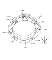
- FIG. 7 is an exploded perspective view of the OIS fixing portion 20.
- the OIS fixing unit 20 includes a coil substrate 21, a connection substrate 22, a base member 23, a position detection unit 24, and the like.
- the coil substrate 21 is a square substrate in plan view, and has a circular opening 21a at the center.
- the coil substrate 21 has wire fixing holes 21b into which the other end (lower end) of the suspension wire 30 is inserted at four corners. Further, the coil substrate 21 has a positioning hole 21c at a position intersecting the diagonal direction at the peripheral edge of the opening 21a.
- the coil substrate 21 has an OIS coil portion 211 at a position facing the magnet portion 122 in the optical axis direction.
- the OIS coil section 211 has four OIS coils 211A to 211D corresponding to the permanent magnets 122A to 122D.
- the size and arrangement of the OIS coils 211A to 211D and the permanent magnets 122A to 122D are set so that the magnetic fields radiated from the bottom surfaces of the permanent magnets 122A to 122D cross the long side portions of the OIS coils 211A to 211D in the Z direction. Is done.
- the magnet part 122 and the OIS coil part 211 constitute an OIS voice coil motor.
- connection substrate 22 is a square substrate in plan view like the coil substrate 21, and has a circular opening 22a in the center.
- the connection substrate 22 has a positioning hole 22b at a position corresponding to the positioning hole 21c of the coil substrate 21 at the periphery of the opening 22a.
- the connection board 22 has control terminals 22c formed by bending downward on two sides along the Y direction.
- the connection substrate 22 has power supply terminals 22d for supplying power to the coil portion for OIS 211 at four locations intersecting the diagonal direction of the inner peripheral edge of the opening 22a.
- the connection board 22 includes a power line (not shown) for supplying power to the AF coil unit 112 and the OIS coil unit 211, and a signal line (not shown) for detection signals output from the position detection unit 24.
- a position detection unit 24 that detects the position of the OIS movable unit 10 in the XY plane is disposed on the back surface of the connection substrate 22.
- the position detection unit 24 includes, for example, Hall elements 24A and 24B (magnetic sensors) that detect a magnetic field using the Hall effect.
- Hall elements 24 ⁇ / b> A and 24 ⁇ / b> B are disposed at substantially the center of each of adjacent two sides of the lower surface of connection substrate 22.
- the position of the OIS movable unit 10 in the XY plane can be specified by detecting the magnetic field formed by the magnet unit 122 with the Hall elements 24A and 24B.
- a position detection magnet may be arranged in the OIS movable unit 10.
- the base member 23 is a square member in plan view like the coil substrate 21 and has a circular opening 23a in the center.
- the base member 23 has positioning bosses 23b at positions corresponding to the positioning holes 21c of the coil substrate 21 and the positioning holes 22b of the connection substrate 22 at the peripheral edge of the opening 23a.
- the base member 23 has a recess 23c at a position corresponding to the control terminal 22c of the connection board 22 at the peripheral edge.
- the recess 23c is formed in a taper shape that expands outwards downward.
- the base member 23 includes a hall element accommodating portion 23d that accommodates the hall elements 24A and 24B and a terminal accommodating portion 23e that accommodates the power supply terminal 22d of the connection substrate 22 at the peripheral edge of the opening 23a.
- the coil substrate 21 and the connection substrate 22 are bonded together by soldering. As a result, the OIS coil portion 211 and the power supply line (not shown) of the connection substrate 22 are electrically connected.
- the positioning hole 21 c of the coil substrate 21 and the positioning hole 22 b of the connection substrate 22 are inserted into the positioning boss 23 b of the base member 23, and the coil substrate 21 and the connection substrate 22 are placed on the base member 23.
- the coil substrate 21 and the connection substrate 22 are fixed to the base member 23 by engaging the control terminal 22 c of the connection substrate 22 with the recess 23 c of the base member 23. In this way, the OIS fixing portion 20 is assembled.
- the lens driving device 1 includes the magnet unit 122 (OIS magnet unit) arranged in the AF driving unit and the OIS coil unit 211 arranged apart from the magnet unit 122 in the optical axis direction.
- An OIS drive unit that performs shake correction by swinging the unit 10 in a plane orthogonal to the optical axis direction is provided.
- each of the suspension wires 33A and 33B is inserted into the wire connecting portion 132g of the upper leaf spring 132 and the wire connecting portion 131g of the upper leaf spring 131, respectively, and fixed by soldering.
- One end of each of the suspension wires 32A and 32B is inserted into the wire connection portion 133c of the power supply line portion 133 and the wire connection portion 134c of the power supply line portion 134, and is fixed by soldering.
- One end of each of the suspension wires 31A and 31B is inserted into the wire connection part 135b of the signal line part 135 and the wire connection part 136b of the signal line part 136, respectively, and is fixed by soldering.
- the other end (lower end) of the suspension wire 30 is inserted into the wire fixing hole 21b of the coil substrate 21 and fixed by soldering.
- the suspension wire 30 is electrically connected to the power supply line and the signal line of the connection board 22. That is, power supply to the AF coil unit 112 and the Hall element 161 and operation control of the Hall element 161 can be performed via the suspension wire 30 and the upper elastic support portion 13.
- a damper material (not shown) is arranged on the damper material arrangement part 121d (including the upper part of the wire insertion part 121a) of the magnet holder 121 so as to surround the suspension wire 30.
- the damper material is interposed between the upper leaf springs 131 and 132 and the magnet holder 121. Since a damper material (not shown) is interposed between the upper leaf springs 131 and 132 and the magnet holder 121, occurrence of unnecessary resonance (higher-order resonance mode) is suppressed, so that operation stability is ensured. be able to.
- the damper material can be easily applied to the damper material arrangement portion 121d using a dispenser.
- an ultraviolet curable silicone gel can be applied.
- the lens cover 1 is attached to the lens driving device 1 so that the lower end portion of the shield cover 2 is in contact with the ground terminal (not shown) of the connection substrate 22. Since the shield cover 2 is grounded via a ground terminal (not shown), EMC noise can be blocked.
- the OIS coil unit 211 When the lens drive device 1 performs shake correction, the OIS coil unit 211 is energized.
- Lorentz force is generated in the OIS coil unit 211 due to the interaction between the magnetic field of the magnet unit 122 and the current flowing in the OIS coil unit 211 (Fleming's left-hand rule).
- the direction of the Lorentz force is a direction (Y direction or X direction) orthogonal to the direction of the magnetic field (Z direction) and the direction of the current flowing in the long side portion of the OIS coil section 211 (X direction or Y direction). Since the OIS coil portion 211 is fixed, a reaction force acts on the magnet portion 122. This reaction force becomes the driving force of the voice coil motor for OIS, and the OIS movable portion 10 having the magnet portion 122 swings in the XY plane, and shake correction is performed.
- the AF coil unit 112 When the lens driving device 1 performs automatic focusing, the AF coil unit 112 is energized.
- the AF coil unit 112 When the AF coil unit 112 is energized, Lorentz force is generated in the AF coil unit 112 due to the interaction between the magnetic field of the magnet unit 122 and the current flowing through the AF coil unit 112.
- the direction of the Lorentz force is a direction (Z direction) orthogonal to the direction of the magnetic field (X direction or Y direction) and the direction of the current flowing in the AF coil section 211 (Y direction or X direction). Since the magnet portion 122 is fixed, a reaction force acts on the AF coil portion 112. This reaction force becomes the driving force of the voice coil motor for AF, and the AF movable portion 11 having the AF coil portion 112 moves in the optical axis direction, and focusing is performed.
- the AF movable portion 11 is suspended between the infinity position and the macro position by the upper leaf springs 131 and 132 and the lower leaf spring 14 (hereinafter referred to as “reference state”). "). That is, in the OIS movable portion 10, the AF movable portion 11 (lens holder 111) is positioned with respect to the AF fixing portion 12 (magnet holder 121) by the upper leaf springs 131 and 132 and the lower leaf spring 14. Elastically supported to be displaceable on both sides in the Z direction.
- the direction of the current is controlled according to whether the AF movable unit 11 is moved from the reference state to the macro position side or to the infinity position side. Further, the magnitude of the current is controlled according to the moving distance of the AF movable unit 11.
- the AF movable unit 11 moves to the infinity position side during focusing, the lower surface of the projection 111d of the lens holder 111 approaches the upper surface of the magnet unit 122 and finally comes into contact. That is, the movement toward the infinity position side is restricted by the lower surface of the protruding portion 111 d of the lens holder 111 and the upper surface of the magnet portion 122.
- the AF movable portion 11 moves to the macro position side during focusing, the upper surface of the protruding portion 111d of the lens holder 111 approaches the lower surface of the stopper portion 121b of the magnet holder 121 and finally comes into contact. That is, the movement toward the macro position side is restricted by the upper surface of the protruding portion 111 d of the lens holder 111 and the lower surface of the stopper portion 121 b of the magnet holder 121.
- closed loop control is performed based on the detection signal of the position detection unit 16. According to the closed loop control method, it is not necessary to consider the hysteresis characteristics of the voice coil motor, and it is possible to directly detect that the position of the AF movable portion 11 is stable. Furthermore, automatic focusing of the image plane detection method can also be supported. Therefore, the response performance is high, and the speed of the automatic focusing operation can be increased.
- FIG. 9 is a diagram showing the displacement width of the lens portion in the lens driving device 1.
- FIG. 9A shows a neutral state (when no power is supplied), and
- FIG. 9B shows a state when it is dropped.
- the AF movable portion 11 is movable by L1 toward the optical axis direction imaging side (hereinafter referred to as “lower movable range L1”).
- the OIS movable unit 10 is separated from the OIS fixed unit 20 by L2 in order to swing in a plane orthogonal to the optical axis direction (hereinafter referred to as “magnet gap L2”).
- the lower movable range L1 and the magnet gap L2 of the AF movable portion 11 are designed so that the performance required for the lens driving device 1 is realized.
- the separation distance L4 between the sub stopper portion 111i of the lens holder 111 and the OIS fixing portion 20 is set to be smaller than the separation distance L3 between the lens portion and the imaging portion (substantially the same as the allowable displacement range of the lens portion).
- the movable distance of the AF movable portion 11 toward the image forming direction in the optical axis direction is the case where the lens holder 111 does not have the sub stopper portion 111i (lower movable range L1 + magnet gap L2), whereas the sub stopper portion 111i. If there is, L4 ( ⁇ L1 + L2). Therefore, the lens unit is displaced by the movable distance L4 of the AF movable unit 11 to the optical axis direction imaging side when receiving an impact such as dropping. Since the distance L3 between the lens unit and the imaging unit is larger than the maximum displacement L4 of the lens unit, the lens unit collides with the imaging unit even if the lens unit is displaced to the optical axis direction imaging side due to an impact such as dropping. There is no. Therefore, it is possible to prevent the IR filter from being damaged by the collision with the lens unit.
- the movable distance of the AF movable portion 11 is 130 ⁇ L4 ⁇ 260.
- the lower movable range L1 of the AF movable portion 11 is required to be 85 ⁇ m or more and the allowable displacement range of the lens portion is required to be 265 ⁇ m or less is also satisfied. That is, by providing the sub-stopper portion 111i, it is possible to easily perform a dimensional design that satisfies the requirements including the mounting tolerance.
- the lens driving device 1 is interposed between the OIS movable unit 10 (lens holder 111) and the OIS fixed unit 20, and determines the movable distance of the AF movable unit 11 to the image forming side in the optical axis direction.
- a sub-stopper portion 111i that regulates within the allowable displacement range of the portion.
- the sub stopper portion 111i may be provided on the OIS fixing portion 20 side.
- a smartphone as a mobile terminal with a camera is described as an example of a camera mounting device including the camera module A, but the present invention can be applied to a camera mounting device as an information device or a transport device.
- An on-camera device that is an information device is an information device having a camera module and a control unit that processes image information obtained by the camera module.
- a camera-equipped mobile phone, a notebook computer, a tablet terminal, and a portable game machine Web cameras, and in-vehicle devices with cameras (for example, back monitor devices, drive recorder devices).
- the camera mounting apparatus which is a transport apparatus is a transport apparatus which has a control part which processes a camera module and the image acquired with the camera module, for example, includes a motor vehicle.
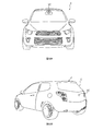
- FIG. 10 is a diagram showing an automobile C as a camera mounting device on which an in-vehicle camera module VC (Vehicle Camera) is mounted.
- 10A is a front view of the automobile C
- FIG. 10B is a rear perspective view of the automobile C.
- the automobile C mounts the camera module A described in the embodiment as the in-vehicle camera module VC.
- the in-vehicle camera module VC is attached to the windshield, for example, facing forward, or attached to the rear gate facing backward.
- This in-vehicle camera module VC is used for a back monitor, a drive recorder, a collision avoidance control, an automatic driving control, and the like.
Landscapes
- Physics & Mathematics (AREA)
- General Physics & Mathematics (AREA)
- Engineering & Computer Science (AREA)
- Multimedia (AREA)
- Signal Processing (AREA)
- Optics & Photonics (AREA)
- Adjustment Of Camera Lenses (AREA)
- Lens Barrels (AREA)
- Studio Devices (AREA)
Abstract
Description
前記オートフォーカス用駆動部に配置される振れ補正用マグネット部と、前記振れ補正用マグネット部に対して光軸方向に離間して配置される振れ補正用コイル部とを有し、前記振れ補正用コイル部と前記振れ補正用マグネット部で構成されるボイスコイルモーターの駆動力を利用して、前記振れ補正用コイル部を含む振れ補正固定部に対して前記振れ補正用マグネット部を含む振れ補正可動部を光軸方向に直交する面内で揺動させることにより振れ補正を行う振れ補正用駆動部と、
前記オートフォーカス可動部と前記振れ補正固定部との間に介在し、前記オートフォーカス可動部の光軸方向結像側への移動可能距離を、前記レンズ部の変位許容範囲内に規制するサブストッパー部と、を備えることを特徴とする。
前記オートフォーカス可動部に装着されるレンズ部と、
前記レンズ部により結像された被写体像を撮像する撮像部と、を備えることを特徴とする。
上記のカメラモジュールを備えることを特徴とする。
図2は、本発明の一実施の形態に係るカメラモジュールAを搭載するスマートフォンMを示す図である。図2AはスマートフォンMの正面図であり、図2BはスマートフォンMの背面図である。
図3、図4に示すように、本実施の形態では、直交座標系(X,Y,Z)を使用して説明する。後述する図においても共通の直交座標系(X,Y,Z)で示している。カメラモジュールAは、スマートフォンMで実際に撮影が行われる場合に、X方向が上下方向(又は左右方向)、Y方向が左右方向(又は上下方向)、Z方向が前後方向となるように搭載される。すなわち、Z方向が光軸方向であり、図中上側が光軸方向受光側(「マクロ位置側)ともいう)、下側が光軸方向結像側(「無限遠位置側」ともいう)となる。
一方、ピント合わせ時にAF可動部11がマクロ位置側へ移動する場合、レンズホルダー111の突出部111dの上面がマグネットホルダー121のストッパー部121bの下面に近づき、最終的に当接する。すなわち、レンズホルダー111の突出部111dの上面とマグネットホルダー121のストッパー部121bの下面によって、マクロ位置側への移動が規制される。
2 シールドカバー
10 OIS可動部(AF用駆動部)
11 AF可動部
111 レンズホルダー
111i サブストッパー部
112 AF用コイル部
12 AF固定部
121 マグネットホルダー
122 マグネット部(AF用マグネット部、OIS用マグネット部)
122A~122D 永久磁石
13 上側弾性支持部
14 下側弾性支持部
15 位置検出用磁石
16 位置検出部
20 OIS固定部
21 コイル基板
211 OIS用コイル部
22 接続基板
23 ベース部材
30 支持部材
M スマートフォン
A カメラモジュール
Claims (6)
- レンズ部の周囲に配置されるオートフォーカス用コイル部と、前記オートフォーカス用コイル部に対して径方向に離間して配置されるオートフォーカス用マグネット部とを有し、前記オートフォーカス用コイル部と前記オートフォーカス用マグネット部とで構成されるボイスコイルモーターの駆動力を利用して、前記オートフォーカス用マグネット部を含むオートフォーカス固定部に対して前記オートフォーカス用コイル部を含むオートフォーカス可動部を光軸方向に移動させることにより自動的にピント合わせを行うオートフォーカス用駆動部と、
前記オートフォーカス用駆動部に配置される振れ補正用マグネット部と、前記振れ補正用マグネット部に対して光軸方向に離間して配置される振れ補正用コイル部とを有し、前記振れ補正用コイル部と前記振れ補正用マグネット部で構成されるボイスコイルモーターの駆動力を利用して、前記振れ補正用コイル部を含む振れ補正固定部に対して前記振れ補正用マグネット部を含む振れ補正可動部を光軸方向に直交する面内で揺動させることにより振れ補正を行う振れ補正用駆動部と、
前記オートフォーカス可動部と前記振れ補正固定部との間に介在し、前記オートフォーカス可動部の光軸方向結像側への移動可能距離を、前記レンズ部の変位許容範囲内に規制するサブストッパー部と、を備えることを特徴とするレンズ駆動装置。 - 前記オートフォーカス用駆動部は、前記オートフォーカス可動部と前記オートフォーカス固定部とを弾性的に接続する弾性支持部を有し、
前記オートフォーカス可動部は、前記弾性支持部によって光軸方向両側に移動可能に支持されることを特徴とする請求項1に記載のレンズ駆動装置。 - 前記オートフォーカス可動部は、前記レンズ部を保持するとともに、外周面に前記オートフォーカス用コイル部が巻線されるレンズホルダーを有し、
前記サブストッパー部は、前記レンズホルダーに光軸方向結像側に向けて形成される複数の突出部であることを特徴とする請求項1又は2に記載のレンズ駆動装置。 - 前記突出部は、光軸方向を中心として均等配置されることを特徴とする請求項3に記載のレンズ駆動装置。
- 請求項1から4のいずれか一項に記載のレンズ駆動装置と、
前記オートフォーカス可動部に装着されるレンズ部と、
前記レンズ部により結像された被写体像を撮像する撮像部と、を備えることを特徴とするカメラモジュール。 - 情報機器または輸送機器であるカメラ搭載装置であって、
請求項5に記載のカメラモジュールを備えることを特徴とするカメラ搭載装置。
Priority Applications (4)
| Application Number | Priority Date | Filing Date | Title |
|---|---|---|---|
| US15/539,395 US10222577B2 (en) | 2014-12-26 | 2015-12-24 | Lens driving device, camera module, and camera mount device |
| EP15872271.0A EP3239757A4 (en) | 2014-12-26 | 2015-12-24 | Lens driving device, camera module, and camera mount device |
| CN201580069832.1A CN107615125B (zh) | 2014-12-26 | 2015-12-24 | 透镜驱动装置、摄像机模块、以及摄像机搭载装置 |
| KR1020177017564A KR102433700B1 (ko) | 2014-12-26 | 2015-12-24 | 렌즈 구동장치, 카메라 모듈, 및 카메라 탑재 장치 |
Applications Claiming Priority (2)
| Application Number | Priority Date | Filing Date | Title |
|---|---|---|---|
| JP2014265987A JP6492653B2 (ja) | 2014-12-26 | 2014-12-26 | レンズ駆動装置、カメラモジュール、及びカメラ搭載装置 |
| JP2014-265987 | 2014-12-26 |
Publications (1)
| Publication Number | Publication Date |
|---|---|
| WO2016103700A1 true WO2016103700A1 (ja) | 2016-06-30 |
Family
ID=56149758
Family Applications (1)
| Application Number | Title | Priority Date | Filing Date |
|---|---|---|---|
| PCT/JP2015/006426 Ceased WO2016103700A1 (ja) | 2014-12-26 | 2015-12-24 | レンズ駆動装置、カメラモジュール、及びカメラ搭載装置 |
Country Status (7)
| Country | Link |
|---|---|
| US (1) | US10222577B2 (ja) |
| EP (1) | EP3239757A4 (ja) |
| JP (1) | JP6492653B2 (ja) |
| KR (1) | KR102433700B1 (ja) |
| CN (1) | CN107615125B (ja) |
| TW (1) | TWI658300B (ja) |
| WO (1) | WO2016103700A1 (ja) |
Cited By (3)
| Publication number | Priority date | Publication date | Assignee | Title |
|---|---|---|---|---|
| CN109143723A (zh) * | 2017-06-19 | 2019-01-04 | 三美电机株式会社 | 透镜驱动装置、摄像机模块及摄像机搭载装置 |
| CN109922253A (zh) * | 2017-12-13 | 2019-06-21 | 北京小米移动软件有限公司 | 镜头防抖方法及装置、移动设备 |
| US20210003812A1 (en) * | 2017-12-28 | 2021-01-07 | Mitsumi Electric Co., Ltd. | Lens driving device, camera module, and camera-mounted device |
Families Citing this family (20)
| Publication number | Priority date | Publication date | Assignee | Title |
|---|---|---|---|---|
| JP6666538B2 (ja) * | 2014-05-14 | 2020-03-18 | ミツミ電機株式会社 | レンズ駆動装置、カメラモジュール、及びカメラ付き携帯端末 |
| EP3040753B1 (en) | 2014-12-30 | 2024-02-21 | LG Innotek Co., Ltd. | Lens moving apparatus |
| KR102311663B1 (ko) | 2015-03-18 | 2021-10-13 | 엘지이노텍 주식회사 | 렌즈 구동 장치, 및 이를 포함하는 카메라 모듈 |
| US10551588B2 (en) | 2015-07-29 | 2020-02-04 | Lg Innotek Co., Ltd. | Lens driving apparatus, camera module, and optical apparatus |
| CN115373102B (zh) | 2016-09-30 | 2026-01-16 | Lg伊诺特有限公司 | 透镜移动设备、包括该设备的相机模块和光学仪器 |
| CN110226122B (zh) * | 2016-11-29 | 2021-09-28 | 三美电机株式会社 | 透镜驱动装置、摄像机模块及摄像机搭载装置 |
| TWI614559B (zh) * | 2016-12-05 | 2018-02-11 | 財團法人工業技術研究院 | 鏡頭裝置 |
| US10656373B1 (en) * | 2017-11-01 | 2020-05-19 | Facebook Technologies, Llc | Apparatuses, systems, and methods for a multistable lens actuator providing multiple stabilized discrete positions |
| WO2019122958A1 (en) * | 2017-12-19 | 2019-06-27 | Arcelormittal | A coated steel substrate |
| JP7021434B2 (ja) * | 2018-02-05 | 2022-02-17 | ミツミ電機株式会社 | レンズ駆動装置、カメラモジュール、及びカメラ搭載装置 |
| CN110275268B (zh) * | 2018-03-14 | 2024-04-30 | 新思考电机有限公司 | 透镜驱动装置、照相机装置以及电子设备 |
| CN110361825B (zh) * | 2018-04-09 | 2024-03-29 | 新思考电机有限公司 | 透镜驱动装置、照相机装置以及电子设备 |
| CN109613676A (zh) * | 2019-01-21 | 2019-04-12 | 湖南新视电子技术有限公司 | 一种双阻尼防护镜头驱动装置 |
| JP7451119B2 (ja) * | 2019-09-19 | 2024-03-18 | キヤノン株式会社 | 撮像装置 |
| US11294196B2 (en) * | 2019-12-10 | 2022-04-05 | Samsung Electro-Mechanics Co., Ltd. | Camera module |
| KR102308327B1 (ko) | 2020-02-05 | 2021-10-06 | 현대종합금속 주식회사 | 극저온 충격인성이 우수하고 전자세 용접 가능한 플럭스 코어드 와이어 |
| KR102813625B1 (ko) * | 2020-02-10 | 2025-05-29 | 삼성전자주식회사 | 카메라 조립체 및 이를 포함하는 전자 장치 |
| KR20220137421A (ko) | 2021-04-02 | 2022-10-12 | 삼성전자주식회사 | 카메라 모듈을 포함하는 전자 장치 |
| EP4625037A4 (en) * | 2022-11-24 | 2026-03-04 | Samsung Electronics Co Ltd | CAMERA MODULE WITH DAMPER |
| CN119279020B (zh) * | 2024-12-11 | 2025-03-18 | 西南林业大学 | 一种冰糖橙采后抗菌保鲜用菌剂及其制备和使用方法 |
Citations (3)
| Publication number | Priority date | Publication date | Assignee | Title |
|---|---|---|---|---|
| JP2011128594A (ja) * | 2009-11-20 | 2011-06-30 | Canon Inc | レンズ鏡筒及びそれを有する光学機器 |
| JP2012058361A (ja) * | 2010-09-07 | 2012-03-22 | Nidec Sankyo Corp | 振れ補正機能付き光学ユニット |
| JP2014126668A (ja) * | 2012-12-26 | 2014-07-07 | Mitsumi Electric Co Ltd | レンズ駆動装置、カメラモジュール、及びカメラ付き携帯端末 |
Family Cites Families (9)
| Publication number | Priority date | Publication date | Assignee | Title |
|---|---|---|---|---|
| US8279289B2 (en) | 2008-10-14 | 2012-10-02 | Nidec Sankyo Corporation | Optical unit with shake correcting function |
| JP5828686B2 (ja) * | 2010-09-07 | 2015-12-09 | 日本電産サンキョー株式会社 | 振れ補正機能付き光学ユニット |
| JP5037719B1 (ja) * | 2011-02-10 | 2012-10-03 | シャープ株式会社 | カメラモジュールの製造方法、カメラモジュール、及び電子機器 |
| JP2012177753A (ja) * | 2011-02-25 | 2012-09-13 | Shicoh Engineering Co Ltd | レンズ駆動装置、オートフォーカスカメラ及びカメラ付きモバイル端末装置 |
| US9151963B2 (en) * | 2011-08-24 | 2015-10-06 | Mitsumi Electric Co., Ltd. | Lens holder driving device including damper compound suppressing undesired resonance |
| JP5849830B2 (ja) * | 2012-03-30 | 2016-02-03 | ミツミ電機株式会社 | レンズホルダ駆動装置、カメラモジュール、およびカメラ付き携帯端末 |
| JP2013083692A (ja) * | 2011-10-06 | 2013-05-09 | Sony Corp | ぶれ補正装置及び撮像装置 |
| KR101980291B1 (ko) * | 2011-12-29 | 2019-05-20 | 엘지이노텍 주식회사 | 보이스 코일 모터 |
| US9323023B2 (en) * | 2012-08-17 | 2016-04-26 | Tdk Taiwan Corporation | Lens focusing device |
-
2014
- 2014-12-26 JP JP2014265987A patent/JP6492653B2/ja active Active
-
2015
- 2015-12-24 WO PCT/JP2015/006426 patent/WO2016103700A1/ja not_active Ceased
- 2015-12-24 KR KR1020177017564A patent/KR102433700B1/ko active Active
- 2015-12-24 EP EP15872271.0A patent/EP3239757A4/en not_active Withdrawn
- 2015-12-24 CN CN201580069832.1A patent/CN107615125B/zh active Active
- 2015-12-24 US US15/539,395 patent/US10222577B2/en active Active
- 2015-12-25 TW TW104143716A patent/TWI658300B/zh not_active IP Right Cessation
Patent Citations (3)
| Publication number | Priority date | Publication date | Assignee | Title |
|---|---|---|---|---|
| JP2011128594A (ja) * | 2009-11-20 | 2011-06-30 | Canon Inc | レンズ鏡筒及びそれを有する光学機器 |
| JP2012058361A (ja) * | 2010-09-07 | 2012-03-22 | Nidec Sankyo Corp | 振れ補正機能付き光学ユニット |
| JP2014126668A (ja) * | 2012-12-26 | 2014-07-07 | Mitsumi Electric Co Ltd | レンズ駆動装置、カメラモジュール、及びカメラ付き携帯端末 |
Non-Patent Citations (1)
| Title |
|---|
| See also references of EP3239757A4 * |
Cited By (5)
| Publication number | Priority date | Publication date | Assignee | Title |
|---|---|---|---|---|
| CN109143723A (zh) * | 2017-06-19 | 2019-01-04 | 三美电机株式会社 | 透镜驱动装置、摄像机模块及摄像机搭载装置 |
| CN109143723B (zh) * | 2017-06-19 | 2022-02-22 | 三美电机株式会社 | 透镜驱动装置、摄像机模块及摄像机搭载装置 |
| CN109922253A (zh) * | 2017-12-13 | 2019-06-21 | 北京小米移动软件有限公司 | 镜头防抖方法及装置、移动设备 |
| US20210003812A1 (en) * | 2017-12-28 | 2021-01-07 | Mitsumi Electric Co., Ltd. | Lens driving device, camera module, and camera-mounted device |
| US11927875B2 (en) * | 2017-12-28 | 2024-03-12 | Mitsumi Electric Co., Ltd. | Lens driving device, camera module, and camera-mounted device |
Also Published As
| Publication number | Publication date |
|---|---|
| EP3239757A4 (en) | 2018-07-04 |
| CN107615125A (zh) | 2018-01-19 |
| EP3239757A1 (en) | 2017-11-01 |
| JP6492653B2 (ja) | 2019-04-03 |
| KR102433700B1 (ko) | 2022-08-18 |
| TW201626027A (zh) | 2016-07-16 |
| JP2016126118A (ja) | 2016-07-11 |
| TWI658300B (zh) | 2019-05-01 |
| US20170371127A1 (en) | 2017-12-28 |
| CN107615125B (zh) | 2020-12-08 |
| US10222577B2 (en) | 2019-03-05 |
| KR20170102247A (ko) | 2017-09-08 |
Similar Documents
| Publication | Publication Date | Title |
|---|---|---|
| JP6492653B2 (ja) | レンズ駆動装置、カメラモジュール、及びカメラ搭載装置 | |
| JP6892611B2 (ja) | レンズ駆動装置、カメラモジュール、及びカメラ搭載装置 | |
| JP6459504B2 (ja) | レンズ駆動装置、カメラモジュール、及びカメラ搭載装置 | |
| CN106687847B (zh) | 透镜驱动装置、摄像机模块、及搭载有摄像机的便携终端 | |
| CN112946856B (zh) | 透镜驱动装置、摄像机模块及摄像机搭载装置 | |
| JP6666538B2 (ja) | レンズ駆動装置、カメラモジュール、及びカメラ付き携帯端末 | |
| JP6703275B2 (ja) | レンズ駆動装置、カメラモジュール、及びカメラ搭載装置 | |
| WO2017038792A1 (ja) | レンズ駆動装置、カメラモジュール、及びカメラ搭載装置 | |
| WO2018100646A1 (ja) | レンズ駆動装置、カメラモジュール、及びカメラ搭載装置 | |
| WO2017138041A1 (ja) | レンズ駆動装置、カメラモジュール、及びカメラ搭載装置 | |
| WO2016103701A1 (ja) | レンズ駆動装置、カメラモジュール、及びカメラ搭載装置 |
Legal Events
| Date | Code | Title | Description |
|---|---|---|---|
| 121 | Ep: the epo has been informed by wipo that ep was designated in this application |
Ref document number: 15872271 Country of ref document: EP Kind code of ref document: A1 |
|
| REEP | Request for entry into the european phase |
Ref document number: 2015872271 Country of ref document: EP |
|
| WWE | Wipo information: entry into national phase |
Ref document number: 15539395 Country of ref document: US |
|
| ENP | Entry into the national phase |
Ref document number: 20177017564 Country of ref document: KR Kind code of ref document: A |
|
| NENP | Non-entry into the national phase |
Ref country code: DE |