WO2016103728A1 - 細胞撮像装置、細胞撮像方法及び試料セル - Google Patents
細胞撮像装置、細胞撮像方法及び試料セル Download PDFInfo
- Publication number
- WO2016103728A1 WO2016103728A1 PCT/JP2015/006469 JP2015006469W WO2016103728A1 WO 2016103728 A1 WO2016103728 A1 WO 2016103728A1 JP 2015006469 W JP2015006469 W JP 2015006469W WO 2016103728 A1 WO2016103728 A1 WO 2016103728A1
- Authority
- WO
- WIPO (PCT)
- Prior art keywords
- cell
- objective lens
- sample
- imaging
- sample cell
- Prior art date
- Legal status (The legal status is an assumption and is not a legal conclusion. Google has not performed a legal analysis and makes no representation as to the accuracy of the status listed.)
- Ceased
Links
Images


Classifications
-
- G—PHYSICS
- G01—MEASURING; TESTING
- G01N—INVESTIGATING OR ANALYSING MATERIALS BY DETERMINING THEIR CHEMICAL OR PHYSICAL PROPERTIES
- G01N33/00—Investigating or analysing materials by specific methods not covered by groups G01N1/00 - G01N31/00
- G01N33/48—Biological material, e.g. blood, urine; Haemocytometers
- G01N33/50—Chemical analysis of biological material, e.g. blood, urine; Testing involving biospecific ligand binding methods; Immunological testing
-
- G—PHYSICS
- G01—MEASURING; TESTING
- G01N—INVESTIGATING OR ANALYSING MATERIALS BY DETERMINING THEIR CHEMICAL OR PHYSICAL PROPERTIES
- G01N15/00—Investigating characteristics of particles; Investigating permeability, pore-volume or surface-area of porous materials
- G01N15/10—Investigating individual particles
- G01N15/14—Optical investigation techniques, e.g. flow cytometry
- G01N15/1468—Optical investigation techniques, e.g. flow cytometry with spatial resolution of the texture or inner structure of the particle
-
- C—CHEMISTRY; METALLURGY
- C12—BIOCHEMISTRY; BEER; SPIRITS; WINE; VINEGAR; MICROBIOLOGY; ENZYMOLOGY; MUTATION OR GENETIC ENGINEERING
- C12Q—MEASURING OR TESTING PROCESSES INVOLVING ENZYMES, NUCLEIC ACIDS OR MICROORGANISMS; COMPOSITIONS OR TEST PAPERS THEREFOR; PROCESSES OF PREPARING SUCH COMPOSITIONS; CONDITION-RESPONSIVE CONTROL IN MICROBIOLOGICAL OR ENZYMOLOGICAL PROCESSES
- C12Q1/00—Measuring or testing processes involving enzymes, nucleic acids or microorganisms; Compositions therefor; Processes of preparing such compositions
- C12Q1/68—Measuring or testing processes involving enzymes, nucleic acids or microorganisms; Compositions therefor; Processes of preparing such compositions involving nucleic acids
-
- G—PHYSICS
- G01—MEASURING; TESTING
- G01N—INVESTIGATING OR ANALYSING MATERIALS BY DETERMINING THEIR CHEMICAL OR PHYSICAL PROPERTIES
- G01N15/00—Investigating characteristics of particles; Investigating permeability, pore-volume or surface-area of porous materials
-
- G—PHYSICS
- G01—MEASURING; TESTING
- G01N—INVESTIGATING OR ANALYSING MATERIALS BY DETERMINING THEIR CHEMICAL OR PHYSICAL PROPERTIES
- G01N15/00—Investigating characteristics of particles; Investigating permeability, pore-volume or surface-area of porous materials
- G01N15/10—Investigating individual particles
- G01N15/14—Optical investigation techniques, e.g. flow cytometry
-
- G—PHYSICS
- G01—MEASURING; TESTING
- G01N—INVESTIGATING OR ANALYSING MATERIALS BY DETERMINING THEIR CHEMICAL OR PHYSICAL PROPERTIES
- G01N21/00—Investigating or analysing materials by the use of optical means, i.e. using sub-millimetre waves, infrared, visible or ultraviolet light
- G01N21/01—Arrangements or apparatus for facilitating the optical investigation
-
- G—PHYSICS
- G01—MEASURING; TESTING
- G01N—INVESTIGATING OR ANALYSING MATERIALS BY DETERMINING THEIR CHEMICAL OR PHYSICAL PROPERTIES
- G01N21/00—Investigating or analysing materials by the use of optical means, i.e. using sub-millimetre waves, infrared, visible or ultraviolet light
- G01N21/17—Systems in which incident light is modified in accordance with the properties of the material investigated
-
- G—PHYSICS
- G01—MEASURING; TESTING
- G01N—INVESTIGATING OR ANALYSING MATERIALS BY DETERMINING THEIR CHEMICAL OR PHYSICAL PROPERTIES
- G01N33/00—Investigating or analysing materials by specific methods not covered by groups G01N1/00 - G01N31/00
- G01N33/48—Biological material, e.g. blood, urine; Haemocytometers
- G01N33/483—Physical analysis of biological material
- G01N33/487—Physical analysis of biological material of liquid biological material
- G01N33/493—Physical analysis of biological material of liquid biological material urine
-
- G—PHYSICS
- G02—OPTICS
- G02B—OPTICAL ELEMENTS, SYSTEMS OR APPARATUS
- G02B21/00—Microscopes
- G02B21/24—Base structure
- G02B21/26—Stages; Adjusting means therefor
-
- G—PHYSICS
- G02—OPTICS
- G02B—OPTICAL ELEMENTS, SYSTEMS OR APPARATUS
- G02B21/00—Microscopes
- G02B21/24—Base structure
- G02B21/30—Base structure with heating device
-
- G—PHYSICS
- G02—OPTICS
- G02B—OPTICAL ELEMENTS, SYSTEMS OR APPARATUS
- G02B21/00—Microscopes
- G02B21/36—Microscopes arranged for photographic purposes or projection purposes or digital imaging or video purposes including associated control and data processing arrangements
-
- G—PHYSICS
- G02—OPTICS
- G02B—OPTICAL ELEMENTS, SYSTEMS OR APPARATUS
- G02B21/00—Microscopes
- G02B21/36—Microscopes arranged for photographic purposes or projection purposes or digital imaging or video purposes including associated control and data processing arrangements
- G02B21/365—Control or image processing arrangements for digital or video microscopes
- G02B21/367—Control or image processing arrangements for digital or video microscopes providing an output produced by processing a plurality of individual source images, e.g. image tiling, montage, composite images, depth sectioning, image comparison
-
- A—HUMAN NECESSITIES
- A61—MEDICAL OR VETERINARY SCIENCE; HYGIENE
- A61B—DIAGNOSIS; SURGERY; IDENTIFICATION
- A61B10/00—Instruments for taking body samples for diagnostic purposes; Other methods or instruments for diagnosis, e.g. for vaccination diagnosis, sex determination or ovulation-period determination; Throat striking implements
-
- A—HUMAN NECESSITIES
- A61—MEDICAL OR VETERINARY SCIENCE; HYGIENE
- A61B—DIAGNOSIS; SURGERY; IDENTIFICATION
- A61B5/00—Measuring for diagnostic purposes; Identification of persons
-
- G—PHYSICS
- G01—MEASURING; TESTING
- G01B—MEASURING LENGTH, THICKNESS OR SIMILAR LINEAR DIMENSIONS; MEASURING ANGLES; MEASURING AREAS; MEASURING IRREGULARITIES OF SURFACES OR CONTOURS
- G01B11/00—Measuring arrangements characterised by the use of optical techniques
-
- G—PHYSICS
- G01—MEASURING; TESTING
- G01N—INVESTIGATING OR ANALYSING MATERIALS BY DETERMINING THEIR CHEMICAL OR PHYSICAL PROPERTIES
- G01N15/00—Investigating characteristics of particles; Investigating permeability, pore-volume or surface-area of porous materials
- G01N15/10—Investigating individual particles
- G01N15/14—Optical investigation techniques, e.g. flow cytometry
- G01N15/1434—Optical arrangements
- G01N2015/1452—Adjustment of focus; Alignment
Definitions
- the present invention relates to a cell imaging device, a cell imaging method, and a sample cell for imaging cells contained in a liquid sample.
- Patent Document 1 discloses an analyzer for imaging a formed component contained in urine in a preparation placed on a stage and analyzing the formed component using the obtained image.
- a focus mark is provided on one surface of the slide glass or the cover glass, and the focus mark is focused.
- the analyzer moves the stage by a predetermined distance in the vertical direction with respect to the objective lens from the in-focus position obtained by the in-focus adjustment by the in-focus mark, and starts observation of the formed portion. Set the analysis start position.
- the stage is moved in the vertical direction little by little from the analysis start position, and when the in-focus state is detected, it is determined that the formed portion is present at the focused position, and the formed portion is imaged at the in-focus position. Subsequently, in order to image a new formed portion in a different visual field area, the stage is moved in the horizontal direction and stopped, and a predetermined distance in the vertical direction about the in-focus position in the previous visual field area. When the in-focus state is detected by moving the stage only, the formed portion is imaged at the in-focus position.
- the focus position is detected by changing the relative distance between the stage and the objective lens in the vertical direction in each visual field region, and the formed portion is imaged at the detected focus position. Since it is executed, imaging takes time. In addition, every time the stage moves to a new visual field region, the stage is moved in the horizontal direction and stopped, so that the formed portion in the preparation vibrates due to the stop of the stage. Therefore, in order to obtain a clear image of the formed portion, it is necessary to wait until the vibration of the formed portion is settled, and it may take a long time for imaging.
- the cell imaging device includes a sample cell having an internal space for holding a liquid sample containing cells, an objective lens, and an imaging unit for imaging cells contained in the liquid sample held in the internal space; A first driving unit for moving at least one of the cell and the objective lens in a first direction; a second driving unit for moving at least one of the sample cell and the objective lens in a second direction different from the first direction; While moving at least one of the sample cell and the objective lens in the first direction, moving the cell contained in the liquid sample held in the internal space while moving at least one of the sample cell and the objective lens in the second direction.
- a liquid sample containing cells is introduced into the internal space of the sample cell including the internal space, and at least one of the sample cell and the objective lens is moved in the first direction. While moving at least one of the lenses in a second direction different from the first direction, the cells contained in the liquid sample held in the internal space are imaged at a plurality of imaging positions.
- the cell imaging device includes an internal space for holding a liquid sample containing cells, a sample cell having a first reference mark and a second reference mark separated from each other, and a liquid held in the internal space.
- An imaging unit for imaging cells contained in the sample a first drive unit for moving at least one of the sample cell and the objective lens in the first direction, and at least one of the sample cell and the objective lens in the first direction
- the second drive unit is controlled to move at least one of the lenses in the second direction, and at least one of the sample cell and the objective lens is moved in the first direction. It controls the driving unit, and a control unit for controlling the imaging unit to image cells contained in a liquid sample held in the internal space at a plurality of imaging positions.
- the first in-focus position of the objective lens with respect to the first reference mark provided in the sample cell and the second in-focus position of the objective lens with respect to the second reference mark provided in the sample cell are detected, and the internal space provided in the sample cell A liquid sample containing cells is introduced, and at least one of the sample cell and the objective lens is moved in the second direction based on the detected first focus position and second focus position, and the sample cell and At least one of the objective lenses is moved in a first direction different from the second direction, and cells contained in the liquid sample held in the internal space are imaged at a plurality of imaging positions.
- the sample cell is a sample cell having an internal space for holding a liquid sample containing cells, an inflow portion for introducing the liquid sample into the internal space, and an outflow for discharging the liquid sample from the internal space. And a first reference mark provided at a position on the inflow portion side in the internal space and used for focus adjustment relating to cell imaging, and provided at a position on the outflow portion side in the internal space and used for focus adjustment relating to cell imaging. A second reference mark.
- the present invention it is possible to shorten the imaging time of the cells in the liquid sample as compared with the prior art.
- FIG. 1 is a schematic diagram illustrating a configuration of a cell imaging device according to Embodiment 1.
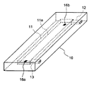
- FIG. 2 is a perspective view showing the configuration of the sample cell according to the first embodiment.
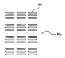
- FIG. 3 is a diagram illustrating the configuration of the reference mark.
- FIG. 4 is a schematic diagram showing a fluid circuit of the cell imaging device.
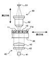
- FIG. 5 is a front view illustrating the configuration of the light source unit and the imaging unit.
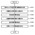
- FIG. 6 is a flowchart showing the procedure of the moving speed determination operation according to the first embodiment.
- FIG. 7 is a diagram for explaining determination of the moving speed of the objective lens.
- FIG. 8 is a flowchart showing the procedure of the urine sample imaging process according to the first embodiment.
- FIG. 9 is a diagram for explaining the offset amount of the objective lens.
- FIG. 1 is a schematic diagram illustrating a configuration of a cell imaging device according to Embodiment 1.
- FIG. 2 is a perspective view showing the configuration of the sample cell according to the first embodiment
- FIG. 10 is a diagram for explaining focus adjustment of the imaging unit in the imaging operation.
- FIG. 11 is a diagram illustrating a display example of a cell image.
- FIG. 12 is a schematic diagram illustrating a configuration of a sample cell according to the second embodiment.
- FIG. 13 is a flowchart illustrating the procedure of the moving speed determination operation according to the second embodiment.
- FIG. 14 is a flowchart showing a procedure of urine sample imaging processing according to the second embodiment.
- FIG. 15 is a schematic diagram illustrating a configuration of the cell imaging device according to the third embodiment.
- FIG. 16 is a side view showing an imaging mechanism of the cell imaging device according to Embodiment 3.
- FIG. 17 is a rear view showing the base block according to the third embodiment.
- FIG. 16 is a side view showing an imaging mechanism of the cell imaging device according to Embodiment 3.
- FIG. 17 is a rear view showing the base block according to the third embodiment.
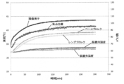
- FIG. 18 is a graph showing changes in the focal position of the objective lens when no heater is provided in the lens block and the base block according to the third embodiment.
- FIG. 19 is a flowchart showing an initialization operation at the time of activation of the cell analyzer according to the third embodiment.
- FIG. 20 is a flowchart of the temperature control process according to the third embodiment.
- FIG. 21 is a graph showing changes in the focal position of the objective lens when the temperature control according to the third embodiment is executed.
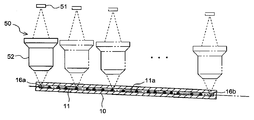
- the cell imaging device 100 includes a sample cell 10, an installation unit 20, a light source unit 40, an imaging unit 50, a driving unit 60, a control unit 70, and a display unit 80.
- the cell imaging device 100 is a device that images cells contained in a liquid sample, for example, cells in a urine sample collected from a subject.
- the sample cell 10 is filled with a urine sample, and the sample cell 10 is horizontally aligned. While moving in the direction, the imaging unit 50 is configured to image cells in the sample cell 10.
- the liquid sample to be imaged may be a biological sample including a plurality of types of cells having different sizes, and may be blood, body cavity fluid, cervical tissue, or the like.
- the sample cell 10 includes an internal space 11 for holding a urine sample, an inflow port 12 connected to the internal space 11, and an outflow port 13 connected to the internal space 11.
- the sample cell 10 is flat and has a rectangular parallelepiped shape extending in one direction, and is made of a light-transmitting material.
- the internal space 11 is a rectangular parallelepiped space that is flat and extends in one direction, and is provided inside the sample cell 10.
- the longitudinal direction of the internal space 11 is aligned with the longitudinal direction of the sample cell 10.
- Each surface of the internal space 11 is formed flat.
- the inlet 12 extends from one end of the internal space 11 in a direction perpendicular to the longitudinal direction. From the other end of the internal space 11, the outlet 13 extends in the same direction as the inlet 12. Each of the inflow port 12 and the outflow port 13 is opened on one side surface of the sample cell 10.
- the sample cell 10 includes a first reference mark 16a at a position on the outlet 13 side of the internal space 11, and a second reference mark 16b at a position on the inlet 12 side of the internal space 11.
- the first reference mark 16 a and the second reference mark 16 b are provided on the bottom surface 11 a of the internal space 11.
- the first reference mark 16 a and the second reference mark 16 b may be provided at a place other than the bottom surface 11 a of the internal space 11, such as the top surface, bottom surface, or top surface of the internal space 11 of the sample cell 10.
- the shape of the first fiducial mark 16a will be described with reference to FIG. Since the shape of the second reference mark 16b is the same as the shape of the first reference mark 16a, description of the shape of the second reference mark 16b is omitted.
- the first fiducial mark 16a includes a plurality of fine grooves 161 formed by laser processing.
- the fine groove 161 has a line width of several ⁇ m and a length of several tens of ⁇ m.
- One set of three fine grooves 161 parallel to each other is formed, and a plurality of sets of fine grooves 161 are formed in a rectangular region to form a first reference mark 16a.
- the longitudinal direction of each fine groove 161 extends in the same direction as the longitudinal direction of the internal space 1 of the sample cell 10.
- the inlet 12 of the sample cell 10 is connected to the suction pipe 151 via a tube and an electromagnetic valve.
- the outlet 13 of the sample cell 10 is connected to the pump 152 via a tube and a solenoid valve.
- the pump 152 is connected to a container 153 that contains a buffer solution via a tube and an electromagnetic valve. Buffer is filled into the tube for introduction of the urine sample.
- the container 153 is connected to the cleaning tank 154 via a tube and an electromagnetic valve.
- the buffer solution is supplied to the cleaning tank 154 and is also used as a cleaning solution.
- a waste liquid container 155 is provided below the cleaning tank 154.
- the suction tube 151 is inserted into a sample container 160 that is a urine collection tube.
- the pump 152 By operating the pump 152, the urine sample in the sample container 160 is sucked from the suction tube 151.
- the suction tube 151 is extracted from the sample container 160.
- the pump 152 operates to suck air from the suction tube 151 and introduce the urine sample into the internal space 11 from the inlet 12.
- the pump 152 is operated until the urine sample comes out from the outflow port 13, so that the entire internal space 11 is filled with the urine sample.
- the suction tube 151 and the sample cell 10 are washed.
- the suction tube 151 is moved to the cleaning tank 154.
- the pump 152 By operating the pump 152, the buffer solution is supplied to the internal space 11, and the internal space 11 is washed.
- the urine sample pushed out from the internal space 11 is discharged from the suction tube 151 to the washing tank 154.
- the pump 152 when the pump 152 is operated, the buffer solution is discharged from the suction pipe 151 and the inside of the suction pipe 151 is washed.
- a buffer solution is supplied from the container 153 to the cleaning tank 154, and the outside of the suction tube 151 is cleaned. Waste liquid from the cleaning tank 154 is stored in a waste liquid container 155.
- the next urine sample is sucked by the suction tube 151 and introduced into the internal space 11 of the sample cell 10.
- the sample cell 10 is fixed to the installation unit 20 so that the bottom surface 11a provided with the first reference mark 16a and the second reference mark 16b is on the lower side.
- the sample cell 10 is fixed to the installation part 20 so as to be inclined at a predetermined angle in a predetermined direction with respect to the horizontal direction. Even if the installation unit 20 is configured so that the sample cell 10 does not tilt with respect to the horizontal direction, the sample cell 10 may be slightly tilted with respect to the horizontal direction due to machine differences. It may be tilted upward or downward with respect to the direction.
- the direction in which the objective lens 52 is moved can be made constant in each urine sample in the imaging operation described later.
- the movement mechanism and movement control of the lens 52 can be simplified.
- the sample cell 10 is attached to the installation part 20 so that it cannot be removed.
- the sample cell 10 may be disposable.
- the installation unit 20 is configured so that the sample cell 10 can be attached and detached.
- the drive unit 60 includes a first drive unit 61 and a second drive unit 62, and moves the sample cell 10 and the objective lens 52 of the imaging unit 50.
- the first drive unit 61 includes an electric motor.
- the installation unit 20 is moved by the first drive unit 61 in a first direction that is one direction in the horizontal direction.
- the first direction is a direction in which the internal space 11 is extended.
- the light source unit 40 is provided below the installation unit 20.
- the light source unit 40 includes an LED light source 41, a diffusion plate 42, and a lens 43.
- the light source 41 is a pulsed light source that emits pulses at regular intervals, and each illumination time is 140 to 200 ⁇ sec.
- the 2nd direction which is the optical axis direction of the light source part 40 is a direction which cross
- the light source 41 irradiates light upward.
- a diffusion plate 42 and a lens 43 are disposed above the light source 41. The light emitted from the light source 41 is diffused by the diffusion plate 42 and converted into parallel light by the lens 43. The parallel light is applied to the sample cell 10.
- the imaging unit 50 is provided above the installation unit 20.
- the imaging unit 50 includes an imaging element 51 that is a CCD image sensor or a CMOS image sensor, and an objective lens 52.
- the imaging element 51 and the objective lens 52 are arranged along the same optical axis as the light source unit 40 so that the imaging element 51 is on the upper side and the objective lens 52 is on the lower side.
- the image sensor 51 and the objective lens 52 are held in one lens barrel. That is, the distance between the image sensor 51 and the objective lens 52 does not change.
- the magnification of the objective lens 52 is 15 times, but it is a magnification that can enlarge the image of other formed components such as white blood cells, red blood cells, epithelial cells, etc., and cylinders in the urine to an appropriate size. If there is, it is not limited to 15 times.
- the second drive unit 62 includes an electric motor.
- the imaging unit 50 is moved in the second direction by the second driving unit 62.
- the focus of the objective lens 52 is adjusted by moving the imaging unit 50 in the second direction.
- the control unit 70 includes a microcomputer and a memory, and controls each of the light source unit 40, the imaging unit 50, the first drive unit 61, the second drive unit 62, and the display unit 80.
- the image obtained by the imaging unit 50 is given to the control unit 70.
- the control unit 70 performs predetermined processing on the acquired image.
- the control unit 70 includes a focus detection unit 71 that performs an automatic focusing operation of the imaging unit 50.
- the image processing may be executed by a personal computer.
- the control unit 70 communicates with the personal computer, and transmits the cell image to the personal computer.
- the personal computer performs image processing such as cutting out a partial image for each cell.
- the display unit 80 includes a liquid crystal display panel.
- the display unit 80 is connected to the control unit 70 and is controlled by the control unit 70 to display a screen.
- the display unit 80 displays a captured image or a partial image obtained by image processing.
- image processing is executed by a personal computer, a captured image or a partial image obtained by image processing may be displayed on the display unit of the personal computer.
- the cell imaging device 100 images the cells contained in the urine sample filled in the internal space 11 of the sample cell 10 by the imaging unit 50.
- the objective lens 52 is moved at a constant speed in the second direction at a moving speed according to the inclination of the sample cell 10, and a plurality of the imaging units 50 are moved.
- the moving speed of the objective lens 52 in the second direction is determined during the initialization operation of the cell imaging device 100 prior to imaging of the urine sample. The operation of such a cell imaging device 100 will be described below.
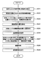
- the cell imaging device 100 executes an initialization operation.
- the initialization operation includes a movement speed determination operation for determining the movement speed of the imaging unit 50 when imaging cells in urine.
- the movement speed determination operation will be described with reference to FIG.
- step S ⁇ b> 101 the control unit 70 controls the pump 152 to fill the flow path from the container 153 to the suction pipe 151. Thereby, the buffer solution is held in the internal space 11 of the sample cell 10.
- step S102 the control unit 70 controls the first driving unit 61 so that the first reference mark 16a on the outlet 13 side of the sample cell 10 is arranged on the optical axis of the imaging unit 50.
- the position of the installation unit 20 when the first reference mark 16a is arranged on the optical axis of the imaging unit 50 is referred to as an “initial position”.
- the position of the installation unit 20 when the second reference mark 16b on the inlet 12 side of the sample cell 10 is arranged on the optical axis of the imaging unit 50 is referred to as a “final position”.
- step S103 the control unit 70 detects the first focus position, which is the focus position of the objective lens 52 at the initial position.
- the control unit 70 performs the automatic focusing operation three times to detect the first focusing position.
- the second driving unit 62 moves the objective lens 52 in the second direction, and the focusing detection unit 71 detects a state where the first reference mark 16a is in focus.
- the automatic focusing operation is a contrast detection method.
- the position of the objective lens 52 where the contrast of the image obtained by the image sensor 51 is maximized is detected as the focus position of the objective lens 52.
- the detected in-focus position is stored in the memory of the control unit 70.
- ⁇ An automatic focusing operation other than the contrast detection method may be adopted.
- known automatic focusing operations such as a phase difference detection method, a line sensor method, an ultrasonic method, and an infrared method can be employed.
- the control unit 70 excludes one of the obtained three in-focus positions where the numerical value indicating the in-focus position is farthest, and obtains an average value of the remaining two in-focus positions.
- the control unit 70 stores the obtained average value in the memory as the first in-focus position.
- step S104 the control unit 70 controls the first drive unit 61 to move the installation unit 20 to the final position.
- step S105 the control unit 70 detects the second focus position that is the focus position of the objective lens 52 at the final position.
- the control unit 70 performs the automatic focusing operation three times to detect the second focusing position.
- the control unit 70 excludes one of the obtained three in-focus positions where the numerical value indicating the in-focus position is farthest, and obtains an average value of the remaining two in-focus positions.
- the control unit 70 stores the obtained average value in the memory as the second in-focus position.
- the number of automatic focusing operations in detecting the first and second focusing positions is not limited to three. One time may be sufficient and multiple times other than three times may be sufficient. However, since the operation time becomes longer as the number of automatic focusing operations increases, it is preferable to reduce as much as possible. From the viewpoint of detection accuracy, it is preferable to execute the automatic focusing operation a plurality of times.
- the average value of the two in-focus positions is calculated, but the present invention is not limited to this.
- An average value of the three in-focus positions may be set as the first in-focus position, and one of the three in-focus positions may be set as the first in-focus position. The same applies to the second in-focus position.
- step S106 the control unit 70 determines the moving speed of the objective lens 52 using the first focus position and the second focus position.
- the sample cell 10 is installed in the installation unit 20 so as to be inclined with respect to the horizontal direction. As shown in FIG. 7, when the sample cell 10 is inclined, a plurality of positions in the sample cell 10 are viewed. When imaging is performed, the position of the objective lens 52 that is focused on the bottom surface 11a of the internal space 11 is different in each visual field. For this reason, if the sample cell 10 is moved horizontally in the first direction while the objective lens 52 is stationary, the distance between the objective lens 52 and the bottom surface 11a of the sample cell 10 changes, and therefore the bottom surface 11a can be viewed in one field of view.
- the bottom surface 11a is not in focus in other fields of view.
- the straight line 52a is a straight line passing through the first focus position and the second focus position.
- imaging is performed in a plurality of fields of view of the sample cell 10.
- the imaging unit 50 performs imaging a plurality of times while the first drive unit 61 moves the installation unit 20 in the first direction at a constant speed. Since the cells in the urine sample introduced into the internal space 11 are located above the bottom surface 11a, the cell imaging device 100 focuses the objective lens 52 at a position a certain distance above the bottom surface 11a in each field of view.
- the second drive unit 62 moves the imaging unit 50 in the second direction at a constant speed in order to keep the objective lens 52 focused at a position a certain distance above the bottom surface 11a.
- the moving speed of the installation unit 20 in the first direction and the moving speed of the imaging unit 50 in the second direction are combined, and the objective lens 52 and the sample cell 10 are relatively constant in a diagonal direction.
- step S ⁇ b> 106 the moving speed for the objective lens 52 to move relative to the sample cell 10 along the straight line 52 a while the installation unit 20 is moving at a constant speed in the first direction is determined.
- the time from the start to the end of the imaging operation that is, the time during which the second drive unit 62 moves the objective lens 52 (hereinafter referred to as “set time”) is set in advance.
- the set time is also the time for the first drive unit 61 to move the installation unit 20.
- the moving speed of the objective lens 52 is a speed of moving from the first focusing position to the second focusing position during the set time. Specifically, the difference distance between the first focus position and the second focus position in the second direction is calculated, and the moving speed of the objective lens 52 is determined by dividing the calculated difference distance by the set time.
- the focus position is detected in each of these reference marks and moved from the three or more detected focus positions.
- the speed may be determined.
- the control unit 70 stores speed information indicating the moving speed in the memory.
- the speed information is information used for focus adjustment of each field of view of the objective lens 52.
- the speed information is also information reflecting the inclination of the bottom surface 11 a of the internal space 11.
- step S106 the control unit 70 ends the movement speed determination operation.
- the cell imaging device 100 enters a standby state after completing the initialization operation.
- the standby state is a state in which a urine sample can be received.
- the cell imaging apparatus 100 When the cell imaging apparatus 100 receives an instruction to start imaging of the urine sample from the user in the standby state, the cell imaging apparatus 100 executes urine sample imaging processing.
- the urine sample imaging process will be described with reference to FIG.
- step S201 the control unit 70 controls the suction tube 151 and the pump 152 to suck a predetermined amount of the urine sample from the sample container 160 and introduce the urine sample into the internal space 11 of the sample cell 10.
- the urine sample is not mixed with a reagent such as a staining solution or a diluent, and is not subjected to centrifugation.
- step S202 the control unit 70 waits for a predetermined time, for example, 100 seconds.
- a predetermined time for example, 100 seconds.
- the urine sample held in the sample cell 10 is placed in a stationary state for a predetermined time, the cells settle in the urine sample, and many cells are arranged on the bottom surface 11 a of the internal space 11.
- step S203 the control unit 70 controls the first drive unit 61 to move the installation unit 20 to the initial position.
- step S204 the control unit 70 detects the first focus position that is the focus position of the objective lens 52 at the initial position.
- the control unit 70 performs the automatic focusing operation three times to detect the first focusing position.
- the control unit 70 excludes one of the obtained three in-focus positions where the numerical value indicating the in-focus position is the most distant, and obtains an average value of the remaining two in-focus positions.
- the control unit 70 stores the obtained average value in the memory as the first in-focus position.
- the first focus position is detected in the movement speed determination operation
- the first focus position is detected again in step S204 in order to eliminate the shift of the focus position due to the passage of time.
- the temperature of the room in which the cell imaging device 100 is placed may change over time, and the distance between each part of the cell imaging device 100, for example, the distance between the objective lens 52 and the sample cell 10 changes due to the temperature change.
- the focus of the objective lens 52 may not be aligned with the bottom surface 11a due to a temperature change. Therefore, the first focus position is detected again in step S204, and the focus of the objective lens 52 is adjusted to the bottom surface 11a of the internal space 11.
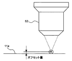
- step S205 the control unit 70 obtains an imaging start position corrected to a position above the first in-focus position by a predetermined offset amount.
- the offset amount will be described with reference to FIG.
- the objective lens 52 When the objective lens 52 is at the first in-focus position, the objective lens 52 is focused on the bottom surface 11a. Since most of the cells are arranged on the bottom surface 11a, the objective lens 52 is not focused on the cells, and if an image is taken in this state, an image of the cells becomes unclear. Therefore, in order to focus the objective lens 52 on the cell, the objective lens 52 is moved upward by an amount corresponding to the radius of the cell, and the focus of the objective lens 52 is positioned near the center of the cell.
- the control unit 70 stores the offset amount in advance. If the offset amount is, for example, 5 to 6 ⁇ m, the objective lens 52 is focused on the red blood cells. However, the offset amount does not have to be 5 to 6 ⁇ m, and the offset amount can be appropriately set depending on the size of the cell of interest.
- the first reference mark 16a and the second reference mark 16b are provided at a place other than the bottom surface 11a of the internal space 11 of the sample cell 10.
- the distance in the second direction from the surface to the center position of the cell of interest may be used as the offset amount.
- step S206 the control unit 70 controls the second drive unit 62 to position the objective lens 52 at the imaging start position.
- step S207 the control unit 70 reads speed information from the memory.
- step S208 the control unit 70 executes an imaging operation.
- the control unit 70 controls the first driving unit 61 and the second driving unit 62 to simultaneously move the installation unit 20 in the first direction and move the imaging unit 50 in the second direction.
- the first drive unit 61 moves the installation unit 20 in the first direction at a set speed without stopping the installation unit 20 halfway.
- the second drive unit 62 moves the imaging unit 50 in the second direction for a set time at a speed indicated by the speed information without stopping the imaging unit 50 halfway.
- the control unit 70 controls the imaging unit 50 to execute imaging a plurality of times.
- the installation unit 20 moves, the field of view of the objective lens 52 moves from the first reference mark 16a to the second reference mark 16b.
- the imaging unit 50 performs imaging with a plurality of fields of view in the region between the first reference mark 16a and the second reference mark 16b.
- the imaging unit 50 continuously moves in the second direction at the speed indicated in the speed information. Therefore, the objective lens 52 moves relative to the sample cell 10 in parallel with the bottom surface 11 a of the internal space 11. That is, the objective lens 52 moves in the second direction according to the inclination of the internal space 11 of the sample cell 10.
- the focal point of the objective lens 52 is positioned above the bottom surface 11a by an offset amount. For this reason, the focal point of the objective lens 52 moves on a straight line above the bottom surface 11a by an offset amount.
- the focal position of the objective lens 52 is positioned near the bottom surface 11a of the internal space 11 in each field of view.
- the state in which the objective lens 52 is focused on the cell is maintained, and a stable and clear cell image can be obtained.
- the light source 41 emits pulses at regular intervals while the installation unit 20 is continuously moving in the first direction at a constant speed, there is no blur even if the installation unit 20 is not stopped each time imaging is performed. An image can be obtained.
- focus adjustment is performed by moving the objective lens 52 at a constant moving speed at a fixed moving speed without detecting the in-focus state in each field of view. Therefore, it is possible to shorten the time for the imaging operation. Further, the focal position is not affected by the cell concentration or cell size in the urine sample, and the focal position in each field of view can be made uniform. Since imaging is performed while continuously moving the sample cell 10 in the first direction without stopping, there is no need to stop the sample cell 10 for imaging in each field of view, and liquid is generated due to the stop of the sample cell 10. It can suppress that the cell in a sample vibrates. Therefore, it is not necessary to wait for the cell vibration to settle, and a stable and clear cell image can be obtained.
- the installation unit 20 reaches the final position. That is, the second reference mark 16 b is located on the optical axis of the imaging unit 50. At this time, the imaging unit 50 and the installation unit 20 are stopped, and the imaging operation is completed.
- the automatic focusing operation is executed only for the detection of the first focusing position at the initial position for the imaging of one urine sample.
- speed information indicating the determined movement speed and information indicating the detected first in-focus position are stored as information for performing focus adjustment of each field of view, and urine sample imaging is performed.
- the objective lens 52 may be positioned at the initial position using the stored information indicating the first in-focus position.
- the objective lens 52 may not be focused on the bottom surface 11a of the internal space 11 at the first focus position determined in the movement speed determination operation due to the temperature environment in the facility. There is. For this reason, from the viewpoint of obtaining a clear and focused image, it is preferable to detect the first in-focus position for each urine sample.
- the time interval is short, so that a temperature change does not substantially occur. For this reason, it is good also as a structure which detects a 1st focusing position for every several urine samples, for example, every 10 urine samples, instead of detecting a 1st focusing position for every urine sample. Accordingly, it is possible to save time by suppressing the number of detections of the first in-focus position while maintaining a state where the cells are focused on each urine sample.
- an automatic focusing operation may be executed at the initial position and the final position to detect the first focusing position and the second focusing position.
- the control unit 70 determines the moving speed of the imaging unit 50 for each urine sample. Therefore, it is not necessary to execute the movement speed determination operation during the initialization operation. Thereby, the inclination
- step S209 the control unit 70 executes image processing, and cuts out partial images for each cell and other formed component from each image obtained by the imaging unit 50.
- step S210 the control unit 70 displays the cut-out partial image on the display unit 80.
- FIG. 11 shows an image display example in the cell imaging device. As shown in the figure, the display unit 80 displays a plurality of images of cells and other formed components included in one urine sample. After step S210, the control unit 70 ends the urine sample imaging process.
- the relative distance to each of the plurality of positions of the bottom surface 11a of the internal space 11 is detected using an optical or ultrasonic distance sensor, and based on the detected relative distance. Then, the respective coordinates of the plurality of positions may be obtained, and information reflecting the inclination of the sample cell 10 may be obtained based on the obtained coordinates.
- the sample cell 210 included in the cell imaging device does not include a reference mark on the bottom surface 211 a of the internal space 211. Since the other configuration of the cell imaging device is the same as the configuration of the cell imaging device 100 described above, description thereof is omitted.
- the cell imaging device determines the moving speed using a control sample containing standard particles of a set size.
- the standard particles contained in the control sample are uniformly arranged in size.
- the cell imaging device When the user activates the cell imaging device, the cell imaging device performs an initialization operation.
- the initialization operation includes a movement speed determination operation for determining the movement speed of the imaging unit 50 when imaging cells in urine.
- the movement speed determination operation will be described with reference to FIG.
- step S ⁇ b> 121 the control unit 70 controls the suction tube 151 and the pump 152, sucks a predetermined amount of the control sample from the sample container in which the control sample is stored, and introduces the control sample into the internal space 211 of the sample cell 210. .
- step S122 the control unit 70 waits for a predetermined time, for example, 100 seconds.
- a predetermined time for example, 100 seconds.
- the control sample held in the sample cell 210 is placed in a stationary state for a predetermined time, the standard particles settle in the control sample, and many standard particles are arranged on the bottom surface of the internal space 211.
- step S123 the control unit 70 controls the first driving unit 61, and the first position of the internal space 211 of the sample cell 210, for example, the position on the outflow port 13 side, is arranged on the optical axis of the imaging unit 50.
- the installation unit 20 is moved so that the
- step S124 the control unit 70 detects the first in-focus position that is the in-focus position of the objective lens 52 in the first position.
- the control unit 70 performs the automatic focusing operation three times to detect the first focusing position.
- the second driving unit 62 moves the objective lens 52 in the second direction, and the focusing detection unit 71 detects a state where the standard particles existing at the first position are in focus.
- the control unit 70 excludes one of the obtained three in-focus positions where the numerical value indicating the in-focus position is farthest, and obtains an average value of the remaining two in-focus positions.
- the control unit 70 stores the obtained average value in the memory as the first in-focus position.
- step S125 the control unit 70 controls the first driving unit 61, and the second position of the internal space 211 of the sample cell 210, for example, the position on the inlet 12 side, is arranged on the optical axis of the imaging unit 50.
- the installation unit 20 is moved so that the
- step S126 the control unit 70 detects the second in-focus position, which is the in-focus position of the objective lens 52 in the second position.
- the control unit 70 performs the automatic focusing operation three times to detect the second focusing position.
- the control unit 70 excludes one of the obtained three in-focus positions where the numerical value indicating the in-focus position is farthest, and obtains an average value of the remaining two in-focus positions.
- the control unit 70 stores the obtained average value in the memory as the second in-focus position.
- step S127 the control unit 70 determines the moving speed of the objective lens 52 using the first focus position and the second focus position. Since the operation in step S127 is the same as the operation in step S106, the description thereof is omitted. After step S127, the control unit 70 ends the movement speed determination operation.
- the cell imaging device 200 enters a standby state after completing the initialization operation.
- the standby state is a state in which a urine sample can be received.
- the cell imaging apparatus 200 When the cell imaging apparatus 200 receives an instruction to start imaging of the urine sample from the user in the standby state, the cell imaging apparatus 200 executes the urine sample imaging process.
- the urine sample imaging process will be described with reference to FIG.
- step S221 the control unit 70 controls the suction tube 151 and the pump 152 to suck a predetermined amount of the urine sample from the sample container 160 and introduce the urine sample into the internal space 11 of the sample cell 10.
- the urine sample is not mixed with a reagent such as a staining solution or a diluent, and is not subjected to centrifugation.
- step S222 the control unit 70 waits for a predetermined time, for example, 100 seconds.
- a predetermined time for example, 100 seconds.
- step S ⁇ b> 223 the control unit 70 controls the first driving unit 61 to move the installation unit 20 so that the first position of the internal space 211 of the sample cell 210 is arranged on the optical axis of the imaging unit 50. .
- step S224 the control unit 70 detects an imaging start position that is a focus position of the objective lens 52 at the first position.
- the control unit 70 performs the automatic focusing operation three times to detect the imaging start position.
- the focus detection unit 71 detects a state in which the cells present at the first position are in focus.
- the control unit 70 excludes one of the three in-focus positions obtained that is farthest from the numerical value, and obtains an average value of the remaining two in-focus positions.
- the control unit 70 stores the obtained average value in the memory as the imaging start position.
- step S225 the control unit 70 controls the second driving unit 62 to position the objective lens 52 at the imaging start position.
- step S226 the control unit 70 reads speed information from the memory. Since the imaging start position is a position where the cell is in focus, correction by the offset amount is not necessary.
- step S227 the control unit 70 executes an imaging operation. Since the operation in step S227 is the same as the operation in step S208, the description thereof is omitted.
- step S2208 the control unit 70 executes image processing, and cuts out partial images for each cell and other formed portion from each image obtained by the imaging unit 50.
- step S229 the control unit 70 causes the display unit 80 to display the cut-out partial image. After step S229, the control unit 70 ends the urine sample imaging process.
- Embodiment 3 With reference to FIG. 15, another embodiment of the cell imaging device will be described.
- the cell imaging device 100A according to Embodiment 3 is configured to execute temperature control for suppressing focus shift of the objective lens caused by temperature fluctuation.
- the description of the same configuration as that in Embodiment 1 is omitted.
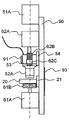
- the cell imaging device 100A includes, as an imaging unit, an objective lens 52A, a lens block 53 that is a lens holding unit that holds the objective lens 52A, and an imaging element 51A that is provided via the lens block 53 and a space.
- the lens block 53 has a hollow cubic shape inside.
- the lower surface of the lens block 53 includes a hole portion into which the upper end portion of the objective lens 52A can be inserted, and holds the objective lens 52A inserted through the hole portion. It is configured to be possible.
- the lens block 53 is attached to the linear slider 54 and is configured to be movable along the linear slider 54 in the second direction that is the optical axis direction.
- the lens block 53 is configured to move in the optical axis direction along the linear slider 54 when the pulley 62B and the belt 62C are driven by the electric motor 62A.
- the electric motor 62A is a stepping motor.
- the image sensor 51 ⁇ / b> A and the linear slider 54 are fixed to a base block 90 that is a substrate, and the lens block 53 moves in the optical axis direction with respect to the image sensor 51. Since the weight of the member moved in the optical axis direction is lighter than that in the case where the lens barrel holding the imaging element and the objective lens is moved in the optical axis direction as in the cell analyzer 100 of the first embodiment, the driving is reduced.
- the electric motor 62A, the pulley 62B, and the belt 62C which are mechanisms, can be reduced in size.
- the installation unit 20 is attached to a linear slider 21.
- the installation unit 20 is installed in the horizontal direction.
- the linear slider 21 is fixed to the base block 90 so as to be inclined at a predetermined angle in the vertical direction with respect to the horizontal direction.
- the inclination angle of the linear slider 21 is very small and is fixed to the base block 90 in a substantially horizontal direction.
- the installation unit 20 moves in a substantially horizontal direction along the linear slider 21.
- Two sample cells 10A and 10B are fixed to the installation unit 20.
- the sample cells 10A and 10B also move integrally with the installation unit 20. Since a plurality of urine samples can be imaged in parallel using the two sample cells 10A and 10B, the imaging process can be performed efficiently.
- the heater 91 for controlling the temperature of the objective lens 52A is attached to the lens block 53.
- the heater 91 is a rubber heater, is attached to the entire side surface of the lens block 53, and is configured to heat the lens block 53.
- a thermistor 92 is attached to the lens block 53, and the temperature of the lens block 53 is detected by the thermistor 92.
- a thermocouple may be used as a temperature sensor.
- the lens block 53 is formed of aluminum having high thermal conductivity. When the lens block 53 is heated by the heater 91, the air inside the lens block 53 is warmed, and the warmed air is transmitted to the objective lens 52A.
- the objective lens 52A includes a lens part and a cylindrical part surrounding the lens part.
- the lens block 53 may be made of a material having high thermal conductivity, and may be made of, for example, copper. Since the heater 91 is provided in the lens block 53 having a larger surface area than the objective lens 52A, the objective lens 52A can be effectively used even when the surface area of the objective lens 52A is small and the heater cannot be installed. Temperature control can be performed.
- the image pickup device 51 ⁇ / b> A, the electric motor 61 ⁇ / b> A, the electric motor 62 ⁇ / b> A, the linear slider 54, and the linear slider 21 are fixed to the base block 90.
- a heater 93 for controlling the temperature of the base block 90 is attached to the surface opposite to the surface on which the image sensor 51A and the like are attached.
- the heater 93 is also a rubber heater and is configured to heat the base block 90.
- a thermistor 94 is attached to the base block 90, and the temperature of the base block 90 is detected by the thermistor 94.
- a thermocouple may be used as a temperature sensor.
- the base block 90 is made of aluminum having high thermal conductivity.
- the base block 90 may be formed of a material having high thermal conductivity, and may be formed of copper, for example.
- the base block 90, the image sensor 51 ⁇ / b> A, the lens block 53, the objective lens 52 ⁇ / b> A, the installation unit 20, the electric motors 61 ⁇ / b> A and 62 ⁇ / b> A are installed in the housing 30.
- the cell analyzer 100A is provided with a temperature sensor 95 for detecting the ambient temperature outside the apparatus.
- FIG. 18 is a graph showing changes in the focal position of the objective lens 52A when no heater is provided in the lens block 53 and the base block 90.
- This graph shows the experimental results when the ambient temperature of the cell analyzer 100A is 32 ° C.
- the temperature of the image sensor 51A rises and the temperature of the lens block 53 rises as the imaging operation is performed after the apparatus is started.
- the “number of pulses” shown on the vertical axis on the right side of the graph of FIG. 18 indicates the number of drive pulses given to the motor 62A in order to adjust the objective lens 52A from its origin position to a predetermined focal position.
- the focal position of the objective lens 52A shifts, and the number of drive pulses for adjusting the objective lens 52A to a predetermined focal position increases.
- a heater 91 is attached to the lens block 53 that holds the objective lens 52A, and the lens block 53 is controlled to a constant temperature by the heater 91. Specifically, the lens block 53 is controlled to 41 ° C. Since the heat of the heater 91 is transmitted to the objective lens 52A through the lens block 53, the temperature of the objective lens 52A is also kept constant. Therefore, the temperature fluctuation of the objective lens 52A is suppressed, and the occurrence of focus shift can be suppressed.
- the temperature of the objective lens 52A may affect not only the heat from the imaging element 51A but also the ambient temperature of the cell imaging device 100A.
- a heater 93 is also attached to the base block 90, and the base block 90 is controlled to a constant temperature.
- the base block 90 is controlled to have the same temperature as the lens block 53, and specifically, is controlled to 41 ° C. Since the base block 90 is disposed in the housing 30 and the air in and out of the housing 30 is blocked, the temperature of the air in the housing 30 is maintained at substantially the same temperature as the base block 90. Temperature fluctuation is suppressed.
- the temperature of the air around the objective lens 52A arranged in the housing 30 can be maintained at substantially the same temperature as the base block 90, the influence due to the change in the ambient temperature of the cell imaging device 100A can be suppressed, The focus shift of the objective lens 52A can be further suppressed.
- the lens block 53 holding the objective lens 52A and the image sensor 51A are arranged so as to be separated from each other through a space, it is possible to suppress heat conduction from occurring. For this reason, it is possible to suppress the heat generated by the heat generation of the imaging element 51A from being transmitted to the objective lens 52A, and to further prevent the focus shift from occurring due to the temperature rise of the objective lens 52A.
- FIG. 19 is a flowchart showing an initialization operation when the cell analyzer 100A is activated.
- the control unit 70 based on the detection result from the temperature sensor 95, in step S321, the outside temperature T, that is, the temperature in the room where the cell analyzer 100A is installed is equal to or higher than T1. Determine whether or not.
- the temperature T1 is 15 ° C., for example, but may be another temperature.
- the control unit 70 starts temperature control by the heaters 91 and 93 in step S322, and determines whether or not the time M1 has elapsed in step S323.
- the time M1 is, for example, 15 minutes, but may be another time.
- the control unit 70 performs a moving speed determination operation in step S327.
- the movement speed determination operation is the same as the operation described in FIG. After the movement speed determination operation, the control unit 70 shifts to standby in step S328.
- the control unit 70 determines whether or not the apparatus outside temperature T is equal to or higher than T2 in step S324.
- the temperature T2 is 10 ° C., for example, but may be any other temperature as long as the temperature is lower than the temperature T1.
- the controller 70 starts temperature control by the heaters 91 and 93 in step S325, and determines whether or not the time M2 has elapsed in step S326.
- the time M2 is, for example, 25 minutes, but may be another time as long as it is longer than the time M1.
- the control unit 70 When the time M2 has elapsed, the control unit 70 performs a moving speed determination operation in step S327, and shifts to standby in step S328.
- the control unit 70 performs a moving speed determination operation in step S327, and shifts to standby in step S328.
- the control unit 70 displays “Imaging not possible” on the display unit 80 in step S329, and returns to step S321 without shifting to standby.
- the ambient temperature of the cell analyzer 100A is too low with respect to the normally assumed temperature, even if the temperature control by the heaters 91 and 93 is performed, the objective lens 52A may be out of focus. Therefore, in such a case, it is possible to prevent imaging with poor accuracy by prohibiting the imaging operation.
- the control unit 70 determines whether or not the temperature of the lens block 53, that is, the temperature of the objective lens 52A is equal to or higher than the target temperature TG based on the detection result from the thermistor 92 in step S421. Determine whether.
- the target temperature TG is 41 ° C., for example.
- the control unit 70 turns on the heater 91 in step S423.
- the control unit 70 turns off the heater 91 in step S422.
- step S424 the control unit 70 determines whether or not the temperature of the base block 90 is equal to or higher than the target temperature TG based on the detection result from the thermistor 94.
- the target temperature TG is 41 ° C., for example.
- the control unit 70 turns on the heater 93 in step S426.
- the control unit 70 turns off the heater 93 in step S425.
- the control unit 70 determines whether or not a shutdown instruction is accepted in step S427. If there is no shutdown instruction, the processing of steps S421 to S426 is repeated. Accordingly, the operation is repeated such that the heater is turned off when the objective lens 52A and the base block 90 reach the target temperature TG, and the heater is turned on when the temperature becomes lower than the target temperature TG. The temperature of block 90 can be maintained near the target temperature TG .
- the base block 90 and the lens block 53 are stable at 41 ° C. in about 10 minutes.
- the focal position of the objective lens 52A is hardly displaced. Based on the focal position of the objective lens 52A after about 15 minutes from the start of the apparatus, the deviation of the focal position of the objective lens 52A is within 5 pulses, and the fluctuation range of the focal position compared to the case of FIG. Can be greatly reduced.
- the focal position of the objective lens 52A can be quickly stabilized. Therefore, after the focus position is stabilized, the frequency of focus adjustment of the objective lens 52A can be reduced, and the imaging process can be performed efficiently. For example, the number of times of focus adjustment each time a new urine sample is imaged can be reduced, and the imaging process can be performed quickly.
- the target temperature of the base block 90 and the lens block 53 may not be 41 ° C., but is preferably higher than the ambient temperature of the cell analyzer 100A, and is generally set to room temperature in the technical field of the present invention, for example.
- the temperature is preferably higher than 25 ° C.
- the temperature of the base block 90 and the lens block 53 can be stabilized earlier as the target temperature is made closer to the temperature of the image sensor 51A.
- the target temperature is particularly preferably 38 ° C. or higher and lower than 42 ° C. because it may affect cells.
Landscapes
- Chemical & Material Sciences (AREA)
- Health & Medical Sciences (AREA)
- Physics & Mathematics (AREA)
- Life Sciences & Earth Sciences (AREA)
- Engineering & Computer Science (AREA)
- Analytical Chemistry (AREA)
- General Physics & Mathematics (AREA)
- Immunology (AREA)
- Biochemistry (AREA)
- General Health & Medical Sciences (AREA)
- Pathology (AREA)
- Biomedical Technology (AREA)
- Urology & Nephrology (AREA)
- Optics & Photonics (AREA)
- Molecular Biology (AREA)
- Hematology (AREA)
- Multimedia (AREA)
- Dispersion Chemistry (AREA)
- Medicinal Chemistry (AREA)
- Biophysics (AREA)
- Food Science & Technology (AREA)
- Organic Chemistry (AREA)
- Proteomics, Peptides & Aminoacids (AREA)
- Biotechnology (AREA)
- Microbiology (AREA)
- Wood Science & Technology (AREA)
- Zoology (AREA)
- Computer Vision & Pattern Recognition (AREA)
- Bioinformatics & Cheminformatics (AREA)
- General Engineering & Computer Science (AREA)
- Genetics & Genomics (AREA)
- Cell Biology (AREA)
- Investigating Or Analysing Materials By Optical Means (AREA)
- Investigating Or Analysing Biological Materials (AREA)
- Microscoopes, Condenser (AREA)
- Optical Measuring Cells (AREA)
Abstract
Description
細胞撮像装置は、細胞を含む液体試料を保持するための内部空間、並びに、互いに離れた第1基準マーク及び第2基準マークを備える試料セルと、対物レンズを備え、内部空間に保持された液体試料に含まれる細胞を撮像するための撮像部と、試料セルおよび対物レンズの少なくとも一方を第1方向へ移動させるための第1駆動部と、試料セルおよび対物レンズの少なくとも一方を第1方向と異なる第2方向に移動させるための第2駆動部と、第1基準マークに対する対物レンズの第1合焦位置及び第2基準マークに対する対物レンズの第2合焦位置に基づいて、試料セルおよび対物レンズの少なくとも一方を第2方向に移動させるよう第2駆動部を制御し、且つ、試料セルおよび対物レンズの少なくとも一方を第1方向に移動させるよう第1駆動部を制御し、内部空間に保持された液体試料に含まれる細胞を複数の撮像位置で撮像するよう撮像部を制御するための制御部と、を備える。
<細胞撮像装置の構成>
図1を参照し、細胞撮像装置の構成について説明する。細胞撮像装置100は、試料セル10と、設置部20と、光源部40と、撮像部50と、駆動部60と、制御部70と、表示部80とを備える。細胞撮像装置100は、液体試料に含まれる細胞、例えば、被検者から採取された尿試料中の細胞を撮像する装置であり、試料セル10内に尿試料を充填し、試料セル10を水平方向に移動させている間に、撮像部50で試料セル10内の細胞を撮像するように構成されている。撮像対象となる液体試料としては、大きさの異なる複数種類の細胞を含む生体試料であればよく、例えば、血液、体腔液、子宮頸部組織等であってもよい。
細胞撮像装置100は、試料セル10の内部空間11に充填された尿試料に含まれる細胞を、撮像部50により撮像する。撮像動作においては、試料セル10を第1方向に一定速度で移動させつつ、試料セル10の傾きにしたがった移動速度で対物レンズ52を第2方向に等速移動させ、撮像部50の複数の視野において撮像を実行する。これにより、各視野で合焦状態の検出を行うことなく、内部空間11の底面近傍に焦点が合わせられる。対物レンズ52の第2方向への移動速度は、尿試料の撮像に先立ち、細胞撮像装置100の初期化動作中に決定される。このような細胞撮像装置100の動作について、以下に説明する。
図12に示すように、細胞撮像装置が備える試料セル210は、内部空間211の底面211aに基準マークを備えない。細胞撮像装置のその他の構成は、上述した細胞撮像装置100の構成と同様であるので、その説明を省略する。
図15を参照し、細胞撮像装置の他の実施形態について説明する。実施の形態3に係る細胞撮像装置100Aは、温度変動に起因する対物レンズの焦点ズレを抑制するための温度制御を実行するように構成されている。実施の形態1と同様の構成については説明を省略する。
10 試料セル
11 内部空間
11a 底面
12 流入口
13 流出口
16a 第1基準マーク
16b 第2基準マーク
160 試料容器
20 設置部
40 光源部
50 撮像部
51、51A 撮像素子
52、52A 対物レンズ
53 レンズブロック
60 駆動部
61 第1駆動部
62 第2駆動部
70 制御部
71 合焦検出部
80 表示部
90 ベースブロック
91、93 ヒータ
Claims (24)
- 細胞を含む液体試料を保持するための内部空間を備える試料セルと、
対物レンズを備え、前記内部空間に保持された前記液体試料に含まれる細胞を撮像するための撮像部と、
前記試料セルおよび前記対物レンズの少なくとも一方を第1方向へ移動させるための第1駆動部と、
前記試料セルおよび前記対物レンズの少なくとも一方を前記第1方向と異なる第2方向へ移動させるための第2駆動部と、
前記試料セルおよび前記対物レンズの少なくとも一方を前記第1方向へ移動させている間に、前記試料セルおよび前記対物レンズの少なくとも一方を前記第2方向へ移動させながら、前記内部空間に保持された前記液体試料に含まれる細胞を複数の撮像位置で撮像するよう前記第1駆動部、前記第2駆動部及び前記撮像部を制御するための制御部と、
を備える、
細胞撮像装置。 - 前記第1駆動部は、前記試料セルを前記第1方向に移動させるよう構成され、
前記第2駆動部は、前記対物レンズを前記第2方向に移動させるよう構成されている、
請求項1に記載の細胞撮像装置。 - 前記試料セルは、前記内部空間内で前記液体試料を支持する底面を備え、
前記制御部は、前記試料セルおよび前記対物レンズの少なくとも一方を前記第1方向へ移動させている間に、前記第1方向に対する前記底面の傾きを反映した情報に基づき、前記底面の傾きにしたがって前記試料セルおよび前記対物レンズの少なくとも一方を前記第2方向へ移動させるよう前記第1駆動部及び前記第2駆動部を制御するように構成されている、
請求項1又は2に記載の細胞撮像装置。 - 前記試料セルの位置に関する位置情報を検出する検出部を備え、
前記制御部は、前記試料セルに前記液体試料が導入される前に、前記検出部により前記試料セルの複数位置のそれぞれに関する位置情報を検出し、検出結果に基づいて、前記底面の傾きを反映した情報を取得するように構成されている、
請求項3に記載の細胞撮像装置。 - 前記第1方向に対して前記底面が傾くように前記試料セルが設置される設置部をさらに備え、
前記第1駆動部は、前記設置部を前記第1方向へ移動させるように構成されている、
請求項3又は4に記載の細胞撮像装置。 - 前記制御部は、前記対物レンズの焦点位置が前記複数の撮像位置において前記内部空間の底面近傍に位置づけられるよう、前記試料セルおよび前記対物レンズの少なくとも一方を前記第1方向へ移動させている間に、前記試料セルおよび前記対物レンズの少なくとも一方を前記第2方向へ移動させるよう前記第1駆動部及び前記第2駆動部を制御するように構成されている、
請求項1乃至5の何れか1項に記載の細胞撮像装置。 - 前記制御部は、前記試料セルを停止させることなく前記第1方向へ連続して移動させている間に、前記対物レンズを前記第2方向に連続して移動させるよう前記第1駆動部及び前記第2駆動部を制御するように構成されている、
請求項2に記載の細胞撮像装置。 - 前記制御部は、前記試料セルを前記第1方向へ等速で移動させている間に、前記対物レンズを前記第2方向に等速で移動させるよう、前記第1駆動部及び前記第2駆動部を制御するように構成されている、
請求項7に記載の細胞撮像装置。 - 前記試料セルの内部空間は、前記第1方向に延伸するように構成されている、
請求項1乃至8の何れか1項に記載の細胞撮像装置。 - 前記生体試料は、尿試料である、
請求項1乃至9の何れか1項に記載の細胞撮像装置。 - 前記対物レンズの温度制御を行うためのヒータをさらに備え、
前記ヒータが、前記対物レンズを保持するレンズ保持部に設けられている、
請求項1乃至10の何れか1項に記載の細胞撮像装置。 - 前記撮像部は、所定位置に固定された撮像素子を備え、
前記第2駆動部は、前記レンズ保持部を前記撮像素子に対して前記第2方向に移動させるように構成されている、
請求項11に記載の細胞撮像装置。 - 前記撮像部および前記試料セルが取り付けられた基板と、
前記撮像部、前記試料セル及び前記基板を収容する筐体と、
前記基板の温度制御を行うための第2ヒータと、をさらに備える、
請求項11又は12に記載の細胞撮像装置。 - 前記試料セルの前記内部空間に保持された前記液体試料に含まれる細胞に光を照射するパルス発光光源をさらに備える、
請求項1乃至13の何れか1項に記載の細胞撮像装置。 - 細胞を含む液体試料を、内部空間を備える試料セルの前記内部空間に導入し、
前記試料セルおよび対物レンズの少なくとも一方を第1方向へ移動させている間に、前記試料セルおよび前記対物レンズの少なくとも一方を前記第1方向と異なる第2方向へ移動させながら、前記内部空間に保持された前記液体試料に含まれる細胞を複数の撮像位置で撮像する、
細胞撮像方法。 -
細胞を含む液体試料を保持するための内部空間、並びに、互いに離れた第1基準マーク及び第2基準マークを備える試料セルと、
対物レンズを備え、前記内部空間に保持された前記液体試料に含まれる細胞を撮像するための撮像部と、
前記試料セルおよび前記対物レンズの少なくとも一方を第1方向へ移動させるための第1駆動部と、
前記試料セルおよび前記対物レンズの少なくとも一方を前記第1方向と異なる第2方向に移動させるための第2駆動部と、
前記第1基準マークに対する前記対物レンズの第1合焦位置及び前記第2基準マークに対する前記対物レンズの第2合焦位置に基づいて、前記試料セルおよび前記対物レンズの少なくとも一方を前記第2方向に移動させるよう前記第2駆動部を制御し、且つ、前記試料セルおよび前記対物レンズの少なくとも一方を前記第1方向に移動させるよう前記第1駆動部を制御し、前記内部空間に保持された前記液体試料に含まれる細胞を複数の撮像位置で撮像するよう前記撮像部を制御するための制御部と、
を備える、
細胞撮像装置。 - 前記制御部は、前記第1合焦位置及び前記第2合焦位置に基づいて、前記複数の撮像位置における前記対物レンズの焦点調整を行うための情報を取得し、取得された情報にしたがって、前記試料セルおよび前記対物レンズの少なくとも一方を前記第2方向に移動させるよう前記第2駆動部を制御するように構成されている、
請求項16に記載の細胞撮像装置。 - 前記制御部は、前記第2方向における前記第1合焦位置及び第2合焦位置の相違に基づいて、前記焦点調整を行うための情報を取得するように構成されている、
請求項17に記載の細胞撮像装置。 - 前記制御部は、前記焦点調整を行うための情報として、前記第2方向への前記対物レンズの相対移動速度を決定し、前記試料セルを前記対物レンズに対して前記第1方向に相対的に等速で移動させ、前記対物レンズを前記試料セルに対して前記決定した相対移動速度で前記第2方向に相対的に等速で移動させるよう前記第1駆動部及び前記第2駆動部を制御するように構成されている、
請求項17又は18に記載の細胞撮像装置。 - 前記制御部は、前記第1合焦位置及び前記第2合焦位置に基づき、前記対物レンズを前記第1合焦位置及び前記第2合焦位置を結ぶ直線に沿って相対移動させるよう前記第1駆動部および前記第2駆動部を制御するように構成されている、
請求項16乃至19の何れか1項に記載の細胞撮像装置。 - 前記試料セルは、前記内部空間に前記液体試料を導入するための流入部と、前記内部空間から前記液体試料を排出するための流出部とを備え、
前記第1基準マークは、前記内部空間における前記流入部側の位置に設けられ、
前記第2基準マークは、前記内部空間における前記流出部側の位置に設けられている、
請求項16乃至20の何れか1項に記載の細胞撮像装置。 - 前記試料セルは、前記内部空間内で前記液体試料を支持する底面を備え、
前記第1基準マーク及び前記第2基準マークのそれぞれは、前記内部空間の底面に形成された微細溝である、
請求項16乃至21の何れか1項に記載の細胞撮像装置。 - 試料セルが備える第1基準マークに対する対物レンズの第1合焦位置及び前記試料セルが備える第2基準マークに対する前記対物レンズの第2合焦位置を検出し、
前記試料セルが備える内部空間に、細胞を含む液体試料を導入し、
検出された前記第1合焦位置及び前記第2合焦位置に基づいて、前記試料セルおよび前記対物レンズの少なくとも一方を第2方向に移動させ、且つ、前記試料セルおよび前記対物レンズの少なくとも一方を前記第2方向と異なる第1方向に移動させ、前記内部空間に保持された前記液体試料に含まれる細胞を複数の撮像位置で撮像する、
細胞撮像方法。 - 細胞を含む液体試料を保持するための内部空間を備える試料セルであって、
前記内部空間に前記液体試料を導入するための流入部と、
前記内部空間から前記液体試料を排出するための流出部と、
前記内部空間における前記流入部側の位置に設けられ、前記細胞の撮像に関する焦点調整に用いられる第1基準マークと、
前記内部空間における前記流出部側の位置に設けられ、前記細胞の撮像に関する焦点調整に用いられる第2基準マークと、
を備える、
試料セル。
Priority Applications (7)
| Application Number | Priority Date | Filing Date | Title |
|---|---|---|---|
| EP21206431.5A EP3968004A1 (en) | 2014-12-26 | 2015-12-25 | Cell imaging device, cell imaging method, and sample cell |
| AU2015369316A AU2015369316B2 (en) | 2014-12-26 | 2015-12-25 | Cell imaging device, cell imaging method, and sample cell |
| JP2016565935A JP6268309B2 (ja) | 2014-12-26 | 2015-12-25 | 細胞撮像装置、細胞撮像方法及び試料セル |
| CN202110087060.1A CN112697792B (zh) | 2014-12-26 | 2015-12-25 | 细胞拍摄装置、细胞拍摄方法及试样池 |
| EP15872299.1A EP3239691B1 (en) | 2014-12-26 | 2015-12-25 | Cell imaging device, cell imaging method, and sample cell |
| CN201580069054.6A CN107003233B (zh) | 2014-12-26 | 2015-12-25 | 细胞拍摄装置、细胞拍摄方法及试样池 |
| US15/628,188 US10732168B2 (en) | 2014-12-26 | 2017-06-20 | Cell imaging device, cell imaging method, and sample cell |
Applications Claiming Priority (4)
| Application Number | Priority Date | Filing Date | Title |
|---|---|---|---|
| JP2014-265931 | 2014-12-26 | ||
| JP2014265931 | 2014-12-26 | ||
| JP2014-265984 | 2014-12-26 | ||
| JP2014265984 | 2014-12-26 |
Related Child Applications (1)
| Application Number | Title | Priority Date | Filing Date |
|---|---|---|---|
| US15/628,188 Continuation US10732168B2 (en) | 2014-12-26 | 2017-06-20 | Cell imaging device, cell imaging method, and sample cell |
Publications (1)
| Publication Number | Publication Date |
|---|---|
| WO2016103728A1 true WO2016103728A1 (ja) | 2016-06-30 |
Family
ID=56149785
Family Applications (1)
| Application Number | Title | Priority Date | Filing Date |
|---|---|---|---|
| PCT/JP2015/006469 Ceased WO2016103728A1 (ja) | 2014-12-26 | 2015-12-25 | 細胞撮像装置、細胞撮像方法及び試料セル |
Country Status (6)
| Country | Link |
|---|---|
| US (1) | US10732168B2 (ja) |
| EP (2) | EP3968004A1 (ja) |
| JP (2) | JP6268309B2 (ja) |
| CN (2) | CN112697792B (ja) |
| AU (1) | AU2015369316B2 (ja) |
| WO (1) | WO2016103728A1 (ja) |
Cited By (1)
| Publication number | Priority date | Publication date | Assignee | Title |
|---|---|---|---|---|
| JP2016194438A (ja) * | 2015-03-31 | 2016-11-17 | シスメックス株式会社 | 細胞撮像装置及び細胞撮像方法 |
Families Citing this family (12)
| Publication number | Priority date | Publication date | Assignee | Title |
|---|---|---|---|---|
| EP3343228B1 (en) * | 2015-08-25 | 2023-06-07 | Hitachi High-Tech Corporation | Automated analyzer and automated analysis system |
| CN110220843A (zh) * | 2018-03-01 | 2019-09-10 | 深圳大森智能科技有限公司 | 血液细胞全自动检测装置 |
| JP7131286B2 (ja) * | 2018-10-15 | 2022-09-06 | 株式会社島津製作所 | 画像解析式粒子分析装置 |
| JP7270907B2 (ja) * | 2019-02-27 | 2023-05-11 | 国立大学法人浜松医科大学 | 細胞観察システムおよび細胞観察方法 |
| CN110542686A (zh) * | 2019-09-30 | 2019-12-06 | 广东牧玛生命科技有限公司 | 一种多功能分析仪器 |
| CN113138190B (zh) * | 2020-01-17 | 2024-11-26 | 深圳迈瑞生物医疗电子股份有限公司 | 尿液样本检测设备和检测方法 |
| CN111175301B (zh) * | 2020-03-17 | 2023-03-31 | 桂林优利特医疗电子有限公司 | 一种鞘流显微全厚度流道细胞清晰图像采集方法 |
| US20220299445A1 (en) * | 2020-08-20 | 2022-09-22 | Cheng-Hao KO | Screening Test Paper Reading System |
| JP7610883B2 (ja) * | 2021-01-25 | 2025-01-09 | ナノエンテク インク | 多チャネル試料チップを用いた微細粒子計数方法,及びこれを実現した微細粒子計数装置 |
| CN115901749A (zh) * | 2021-09-30 | 2023-04-04 | 苏州迈瑞科技有限公司 | 尿液样本检测设备和尿液样本检测方法 |
| CN115473999B (zh) * | 2021-12-31 | 2025-12-02 | 深圳市瑞图生物技术有限公司 | 液基细胞的拍摄方法、拍摄装置及存储介质 |
| CN118817672A (zh) * | 2023-04-21 | 2024-10-22 | 深圳迈瑞生物医疗电子股份有限公司 | 尿样本分析仪 |
Citations (3)
| Publication number | Priority date | Publication date | Assignee | Title |
|---|---|---|---|---|
| WO2008007725A1 (en) * | 2006-07-12 | 2008-01-17 | Toyo Boseki Kabushiki Kaisha | Analyzer and use thereof |
| JP2011209573A (ja) * | 2010-03-30 | 2011-10-20 | Sony Corp | 合焦装置、合焦方法、合焦プログラム及び顕微鏡 |
| JP2014134632A (ja) * | 2013-01-09 | 2014-07-24 | Olympus Corp | 撮像装置、顕微鏡システム及び撮像方法 |
Family Cites Families (36)
| Publication number | Priority date | Publication date | Assignee | Title |
|---|---|---|---|---|
| JP2874746B2 (ja) | 1990-11-22 | 1999-03-24 | シスメックス株式会社 | フローイメージングサイトメータにおけるフローセル機構 |
| JP4076249B2 (ja) | 1997-09-24 | 2008-04-16 | オリンパス株式会社 | 自動焦点顕微鏡 |
| US6493135B1 (en) * | 1998-02-17 | 2002-12-10 | Leica Microsystems Heidelberg Gmbh | Temperature regulated microscope |
| JP4085297B2 (ja) | 2000-03-07 | 2008-05-14 | 東洋紡績株式会社 | 尿中有形成分分類装置 |
| JP3736278B2 (ja) * | 2000-04-12 | 2006-01-18 | 松下電器産業株式会社 | 生化学物質の観察方法 |
| US7518652B2 (en) * | 2000-05-03 | 2009-04-14 | Aperio Technologies, Inc. | Method and apparatus for pre-focus in a linear array based slide scanner |
| WO2003005005A1 (en) * | 2001-07-03 | 2003-01-16 | Hitachi, Ltd. | Biological sample optical measuring method and biological sample optical measuring apparatus |
| JP4652049B2 (ja) | 2002-05-28 | 2011-03-16 | オウトジエノミクス・インコーポレーテツド | 自動解析装置用レベル制御ピペット |
| JP2004146670A (ja) * | 2002-10-25 | 2004-05-20 | Riipuru:Kk | マスクのパターン位置の誤差測定方法及びこれに使用される露光装置 |
| JP2005221725A (ja) * | 2004-02-05 | 2005-08-18 | Olympus Corp | 焦点検出方法、自動細胞培養装置用自動焦点検出装置、自動細胞培養装置及び培養容器。 |
| JP2006003653A (ja) * | 2004-06-17 | 2006-01-05 | Olympus Corp | 生体試料観察システム |
| JP2006138654A (ja) * | 2004-11-10 | 2006-06-01 | A & T Corp | 有形成分分析装置および有形成分分析方法 |
| JP4871264B2 (ja) * | 2005-03-17 | 2012-02-08 | 浜松ホトニクス株式会社 | 顕微鏡画像撮像装置 |
| WO2006115863A2 (en) | 2005-04-12 | 2006-11-02 | Caliper Life Sciences, Inc. | Compact optical detection system for microfluidic devices |
| US7663750B2 (en) * | 2005-06-30 | 2010-02-16 | Applied Biosystems, Llc | Two-dimensional spectral imaging system |
| US7718131B2 (en) * | 2005-07-06 | 2010-05-18 | Genetix Limited | Methods and apparatus for imaging and processing of samples in biological sample containers |
| JP4773198B2 (ja) | 2005-12-22 | 2011-09-14 | シスメックス株式会社 | 標本撮像装置及びこれを備える標本分析装置 |
| JP2007248501A (ja) | 2006-03-13 | 2007-09-27 | Horon:Kk | フォーカス調整方法およびフォーカス調整装置 |
| WO2007145233A1 (ja) * | 2006-06-13 | 2007-12-21 | Nikon Corporation | 顕微鏡装置 |
| US8586385B2 (en) * | 2006-12-28 | 2013-11-19 | Intel Corporation | Method and device for biomolecule preparation and detection using magnetic array |
| JP4257863B2 (ja) * | 2007-02-13 | 2009-04-22 | 東レエンジニアリング株式会社 | 自動外観検査装置 |
| WO2008137746A1 (en) * | 2007-05-04 | 2008-11-13 | Aperio Technologies, Inc. | Rapid microscope scanner for volume image acquisition |
| JP2010101959A (ja) * | 2008-10-21 | 2010-05-06 | Olympus Corp | 顕微鏡装置 |
| AU2010229924B2 (en) * | 2009-03-24 | 2016-07-21 | Plus Therapeutics Inc. | Devices and methods of cell capture and analysis |
| US20120100538A1 (en) * | 2009-03-24 | 2012-04-26 | Biocept, Inc. | Devices and methods of cell capture and analysis |
| EP2439511B1 (en) | 2009-06-03 | 2015-08-19 | Hitachi High-Technologies Corporation | Flow type particle image analysis method and device |
| KR100942195B1 (ko) * | 2009-10-14 | 2010-02-11 | 주식회사 나노엔텍 | 형광현미경 및 그 원격제어시스템 |
| CA2842661C (en) * | 2009-10-19 | 2016-02-23 | Ventana Medical Systems, Inc. | Imaging system and techniques |
| JP5638793B2 (ja) * | 2009-12-03 | 2014-12-10 | オリンパス株式会社 | 顕微鏡装置 |
| JP2012013804A (ja) * | 2010-06-29 | 2012-01-19 | Sony Corp | 画像処理装置、画像処理システム、画像処理方法及びプログラム |
| CN103648649A (zh) * | 2011-05-18 | 2014-03-19 | 3M创新有限公司 | 检测选定体积的材料在样本处理装置中存在的系统和方法 |
| WO2013056415A1 (zh) * | 2011-10-18 | 2013-04-25 | 长沙高新技术产业开发区爱威科技实业有限公司 | 样本有形成分分析仪自动检测控制装置及其控制方法 |
| US20140193892A1 (en) | 2012-07-25 | 2014-07-10 | Theranos, Inc. | Image analysis and measurement of biological samples |
| JP6134348B2 (ja) * | 2015-03-31 | 2017-05-24 | シスメックス株式会社 | 細胞撮像装置及び細胞撮像方法 |
| EP3341730A1 (en) * | 2015-08-27 | 2018-07-04 | Quidel Corporation | Immunoassay test device with two fluid flow paths for detection and differentiation of two or more analytes |
| JP6134402B1 (ja) * | 2016-01-29 | 2017-05-24 | シスメックス株式会社 | 生体試料撮像装置及び生体試料撮像方法 |
-
2015
- 2015-12-25 JP JP2016565935A patent/JP6268309B2/ja not_active Expired - Fee Related
- 2015-12-25 EP EP21206431.5A patent/EP3968004A1/en active Pending
- 2015-12-25 CN CN202110087060.1A patent/CN112697792B/zh active Active
- 2015-12-25 WO PCT/JP2015/006469 patent/WO2016103728A1/ja not_active Ceased
- 2015-12-25 EP EP15872299.1A patent/EP3239691B1/en active Active
- 2015-12-25 CN CN201580069054.6A patent/CN107003233B/zh active Active
- 2015-12-25 AU AU2015369316A patent/AU2015369316B2/en active Active
-
2017
- 2017-06-20 US US15/628,188 patent/US10732168B2/en active Active
- 2017-12-25 JP JP2017247505A patent/JP6599965B2/ja active Active
Patent Citations (3)
| Publication number | Priority date | Publication date | Assignee | Title |
|---|---|---|---|---|
| WO2008007725A1 (en) * | 2006-07-12 | 2008-01-17 | Toyo Boseki Kabushiki Kaisha | Analyzer and use thereof |
| JP2011209573A (ja) * | 2010-03-30 | 2011-10-20 | Sony Corp | 合焦装置、合焦方法、合焦プログラム及び顕微鏡 |
| JP2014134632A (ja) * | 2013-01-09 | 2014-07-24 | Olympus Corp | 撮像装置、顕微鏡システム及び撮像方法 |
Non-Patent Citations (1)
| Title |
|---|
| See also references of EP3239691A4 * |
Cited By (1)
| Publication number | Priority date | Publication date | Assignee | Title |
|---|---|---|---|---|
| JP2016194438A (ja) * | 2015-03-31 | 2016-11-17 | シスメックス株式会社 | 細胞撮像装置及び細胞撮像方法 |
Also Published As
| Publication number | Publication date |
|---|---|
| EP3239691A4 (en) | 2018-08-22 |
| AU2015369316A1 (en) | 2017-07-13 |
| EP3239691A1 (en) | 2017-11-01 |
| CN112697792B (zh) | 2024-10-11 |
| EP3239691B1 (en) | 2021-11-17 |
| US10732168B2 (en) | 2020-08-04 |
| JP6268309B2 (ja) | 2018-01-24 |
| CN107003233B (zh) | 2021-02-12 |
| US20170285000A1 (en) | 2017-10-05 |
| JP2018054633A (ja) | 2018-04-05 |
| JPWO2016103728A1 (ja) | 2017-06-22 |
| JP6599965B2 (ja) | 2019-10-30 |
| CN112697792A (zh) | 2021-04-23 |
| EP3968004A1 (en) | 2022-03-16 |
| AU2015369316B2 (en) | 2020-11-26 |
| CN107003233A (zh) | 2017-08-01 |
Similar Documents
| Publication | Publication Date | Title |
|---|---|---|
| JP6599965B2 (ja) | 細胞撮像装置、細胞撮像方法及び試料セル | |
| JP6134348B2 (ja) | 細胞撮像装置及び細胞撮像方法 | |
| US8629382B2 (en) | Auto focus apparatus for detecting a focal point with a setting section for shifting an irradiation position outside an observation field of an imaging section | |
| JP5290690B2 (ja) | 微細粒子のスクリーニング装置 | |
| CN113396352B (zh) | 液浸式显微镜物镜组件及相关系统和方法 | |
| US8917347B2 (en) | Focus control method and culture observation apparatus | |
| JP2015087329A (ja) | 吸引部の位置調整方法及び検体処理装置 | |
| US11977214B2 (en) | Phase difference observation apparatus and cell treatment apparatus | |
| JP2014092427A (ja) | 自動分析装置 | |
| KR102058826B1 (ko) | 세포 배양 장치와 이를 이용한 세포 배양 모니터링 시스템 및 방법 | |
| JP4956289B2 (ja) | 微細粒子のスクリーニング装置および微細粒子のスクリーニング方法 | |
| JP2007309888A (ja) | 分注装置 | |
| JP2010026218A (ja) | 液体供給装置及び顕微鏡 | |
| JP6461580B2 (ja) | スクリーニング装置およびスクリーニング方法 | |
| JP3837145B2 (ja) | 顕微鏡撮像装置 | |
| JP2018028593A (ja) | 観察装置、観察方法及び観察システム | |
| JP2007309889A (ja) | 異物検出装置及び異物検出方法 | |
| JP4020893B2 (ja) | 顕微鏡撮像装置および生体試料観察システム | |
| JP2006138654A (ja) | 有形成分分析装置および有形成分分析方法 | |
| JP4179002B2 (ja) | 顕微鏡装置及びこの顕微鏡装置を用いた薬物効果測定方法 | |
| JP2006090749A (ja) | 温度調整装置 | |
| JP2007264114A (ja) | 液浸顕微鏡装置 | |
| CN121359068A (zh) | 用于具有快速扫描的测序系统的浸没式显微镜布置 | |
| JP2005208626A (ja) | 顕微鏡装置および液浸対物レンズ |
Legal Events
| Date | Code | Title | Description |
|---|---|---|---|
| 121 | Ep: the epo has been informed by wipo that ep was designated in this application |
Ref document number: 15872299 Country of ref document: EP Kind code of ref document: A1 |
|
| ENP | Entry into the national phase |
Ref document number: 2016565935 Country of ref document: JP Kind code of ref document: A |
|
| REEP | Request for entry into the european phase |
Ref document number: 2015872299 Country of ref document: EP |
|
| NENP | Non-entry into the national phase |
Ref country code: DE |
|
| ENP | Entry into the national phase |
Ref document number: 2015369316 Country of ref document: AU Date of ref document: 20151225 Kind code of ref document: A |