WO2016103803A1 - 絶縁電線およびコイル - Google Patents
絶縁電線およびコイル Download PDFInfo
- Publication number
- WO2016103803A1 WO2016103803A1 PCT/JP2015/075972 JP2015075972W WO2016103803A1 WO 2016103803 A1 WO2016103803 A1 WO 2016103803A1 JP 2015075972 W JP2015075972 W JP 2015075972W WO 2016103803 A1 WO2016103803 A1 WO 2016103803A1
- Authority
- WO
- WIPO (PCT)
- Prior art keywords
- thermoplastic resin
- resin layer
- conductor
- flat conductor
- insulated wire
- Prior art date
- Legal status (The legal status is an assumption and is not a legal conclusion. Google has not performed a legal analysis and makes no representation as to the accuracy of the status listed.)
- Ceased
Links
Images


Classifications
-
- H—ELECTRICITY
- H01—ELECTRIC ELEMENTS
- H01B—CABLES; CONDUCTORS; INSULATORS; SELECTION OF MATERIALS FOR THEIR CONDUCTIVE, INSULATING OR DIELECTRIC PROPERTIES
- H01B3/00—Insulators or insulating bodies characterised by the insulating materials; Selection of materials for their insulating or dielectric properties
- H01B3/18—Insulators or insulating bodies characterised by the insulating materials; Selection of materials for their insulating or dielectric properties mainly consisting of organic substances
- H01B3/30—Insulators or insulating bodies characterised by the insulating materials; Selection of materials for their insulating or dielectric properties mainly consisting of organic substances plastics; resins; waxes
- H01B3/42—Insulators or insulating bodies characterised by the insulating materials; Selection of materials for their insulating or dielectric properties mainly consisting of organic substances plastics; resins; waxes polyesters; polyethers; polyacetals
- H01B3/427—Polyethers
-
- C—CHEMISTRY; METALLURGY
- C09—DYES; PAINTS; POLISHES; NATURAL RESINS; ADHESIVES; COMPOSITIONS NOT OTHERWISE PROVIDED FOR; APPLICATIONS OF MATERIALS NOT OTHERWISE PROVIDED FOR
- C09D—COATING COMPOSITIONS, e.g. PAINTS, VARNISHES OR LACQUERS; FILLING PASTES; CHEMICAL PAINT OR INK REMOVERS; INKS; CORRECTING FLUIDS; WOODSTAINS; PASTES OR SOLIDS FOR COLOURING OR PRINTING; USE OF MATERIALS THEREFOR
- C09D167/00—Coating compositions based on polyesters obtained by reactions forming a carboxylic ester link in the main chain; Coating compositions based on derivatives of such polymers
- C09D167/02—Polyesters derived from dicarboxylic acids and dihydroxy compounds
-
- C—CHEMISTRY; METALLURGY
- C09—DYES; PAINTS; POLISHES; NATURAL RESINS; ADHESIVES; COMPOSITIONS NOT OTHERWISE PROVIDED FOR; APPLICATIONS OF MATERIALS NOT OTHERWISE PROVIDED FOR
- C09D—COATING COMPOSITIONS, e.g. PAINTS, VARNISHES OR LACQUERS; FILLING PASTES; CHEMICAL PAINT OR INK REMOVERS; INKS; CORRECTING FLUIDS; WOODSTAINS; PASTES OR SOLIDS FOR COLOURING OR PRINTING; USE OF MATERIALS THEREFOR
- C09D171/00—Coating compositions based on polyethers obtained by reactions forming an ether link in the main chain; Coating compositions based on derivatives of such polymers
-
- C—CHEMISTRY; METALLURGY
- C09—DYES; PAINTS; POLISHES; NATURAL RESINS; ADHESIVES; COMPOSITIONS NOT OTHERWISE PROVIDED FOR; APPLICATIONS OF MATERIALS NOT OTHERWISE PROVIDED FOR
- C09D—COATING COMPOSITIONS, e.g. PAINTS, VARNISHES OR LACQUERS; FILLING PASTES; CHEMICAL PAINT OR INK REMOVERS; INKS; CORRECTING FLUIDS; WOODSTAINS; PASTES OR SOLIDS FOR COLOURING OR PRINTING; USE OF MATERIALS THEREFOR
- C09D179/00—Coating compositions based on macromolecular compounds obtained by reactions forming in the main chain of the macromolecule a linkage containing nitrogen, with or without oxygen, or carbon only, not provided for in groups C09D161/00 - C09D177/00
- C09D179/02—Polyamines
-
- C—CHEMISTRY; METALLURGY
- C09—DYES; PAINTS; POLISHES; NATURAL RESINS; ADHESIVES; COMPOSITIONS NOT OTHERWISE PROVIDED FOR; APPLICATIONS OF MATERIALS NOT OTHERWISE PROVIDED FOR
- C09D—COATING COMPOSITIONS, e.g. PAINTS, VARNISHES OR LACQUERS; FILLING PASTES; CHEMICAL PAINT OR INK REMOVERS; INKS; CORRECTING FLUIDS; WOODSTAINS; PASTES OR SOLIDS FOR COLOURING OR PRINTING; USE OF MATERIALS THEREFOR
- C09D181/00—Coating compositions based on macromolecular compounds obtained by reactions forming in the main chain of the macromolecule a linkage containing sulfur, with or without nitrogen, oxygen, or carbon only; Coating compositions based on polysulfones; Coating compositions based on derivatives of such polymers
- C09D181/02—Polythioethers; Polythioether-ethers
-
- H—ELECTRICITY
- H01—ELECTRIC ELEMENTS
- H01B—CABLES; CONDUCTORS; INSULATORS; SELECTION OF MATERIALS FOR THEIR CONDUCTIVE, INSULATING OR DIELECTRIC PROPERTIES
- H01B1/00—Conductors or conductive bodies characterised by the conductive materials; Selection of materials as conductors
- H01B1/02—Conductors or conductive bodies characterised by the conductive materials; Selection of materials as conductors mainly consisting of metals or alloys
- H01B1/026—Alloys based on copper
-
- H—ELECTRICITY
- H01—ELECTRIC ELEMENTS
- H01B—CABLES; CONDUCTORS; INSULATORS; SELECTION OF MATERIALS FOR THEIR CONDUCTIVE, INSULATING OR DIELECTRIC PROPERTIES
- H01B3/00—Insulators or insulating bodies characterised by the insulating materials; Selection of materials for their insulating or dielectric properties
- H01B3/18—Insulators or insulating bodies characterised by the insulating materials; Selection of materials for their insulating or dielectric properties mainly consisting of organic substances
- H01B3/30—Insulators or insulating bodies characterised by the insulating materials; Selection of materials for their insulating or dielectric properties mainly consisting of organic substances plastics; resins; waxes
-
- H—ELECTRICITY
- H01—ELECTRIC ELEMENTS
- H01B—CABLES; CONDUCTORS; INSULATORS; SELECTION OF MATERIALS FOR THEIR CONDUCTIVE, INSULATING OR DIELECTRIC PROPERTIES
- H01B3/00—Insulators or insulating bodies characterised by the insulating materials; Selection of materials for their insulating or dielectric properties
- H01B3/18—Insulators or insulating bodies characterised by the insulating materials; Selection of materials for their insulating or dielectric properties mainly consisting of organic substances
- H01B3/30—Insulators or insulating bodies characterised by the insulating materials; Selection of materials for their insulating or dielectric properties mainly consisting of organic substances plastics; resins; waxes
- H01B3/301—Macromolecular compounds obtained by reactions forming a linkage containing sulfur with or without nitrogen, oxygen or carbon in the main chain of the macromolecule, not provided for in group H01B3/302
-
- H—ELECTRICITY
- H01—ELECTRIC ELEMENTS
- H01B—CABLES; CONDUCTORS; INSULATORS; SELECTION OF MATERIALS FOR THEIR CONDUCTIVE, INSULATING OR DIELECTRIC PROPERTIES
- H01B3/00—Insulators or insulating bodies characterised by the insulating materials; Selection of materials for their insulating or dielectric properties
- H01B3/18—Insulators or insulating bodies characterised by the insulating materials; Selection of materials for their insulating or dielectric properties mainly consisting of organic substances
- H01B3/30—Insulators or insulating bodies characterised by the insulating materials; Selection of materials for their insulating or dielectric properties mainly consisting of organic substances plastics; resins; waxes
- H01B3/303—Macromolecular compounds obtained by reactions forming a linkage containing nitrogen with or without oxygen or carbon in the main chain of the macromolecule, not provided for in groups H01B3/38 or H01B3/302
- H01B3/306—Polyimides or polyesterimides
-
- H—ELECTRICITY
- H01—ELECTRIC ELEMENTS
- H01B—CABLES; CONDUCTORS; INSULATORS; SELECTION OF MATERIALS FOR THEIR CONDUCTIVE, INSULATING OR DIELECTRIC PROPERTIES
- H01B3/00—Insulators or insulating bodies characterised by the insulating materials; Selection of materials for their insulating or dielectric properties
- H01B3/18—Insulators or insulating bodies characterised by the insulating materials; Selection of materials for their insulating or dielectric properties mainly consisting of organic substances
- H01B3/30—Insulators or insulating bodies characterised by the insulating materials; Selection of materials for their insulating or dielectric properties mainly consisting of organic substances plastics; resins; waxes
- H01B3/42—Insulators or insulating bodies characterised by the insulating materials; Selection of materials for their insulating or dielectric properties mainly consisting of organic substances plastics; resins; waxes polyesters; polyethers; polyacetals
- H01B3/421—Polyesters
- H01B3/422—Linear saturated polyesters derived from dicarboxylic acids and dihydroxy compounds
- H01B3/423—Linear aromatic polyesters
-
- H—ELECTRICITY
- H01—ELECTRIC ELEMENTS
- H01B—CABLES; CONDUCTORS; INSULATORS; SELECTION OF MATERIALS FOR THEIR CONDUCTIVE, INSULATING OR DIELECTRIC PROPERTIES
- H01B7/00—Insulated conductors or cables characterised by their form
-
- H—ELECTRICITY
- H01—ELECTRIC ELEMENTS
- H01B—CABLES; CONDUCTORS; INSULATORS; SELECTION OF MATERIALS FOR THEIR CONDUCTIVE, INSULATING OR DIELECTRIC PROPERTIES
- H01B7/00—Insulated conductors or cables characterised by their form
- H01B7/0009—Details relating to the conductive cores
-
- H—ELECTRICITY
- H01—ELECTRIC ELEMENTS
- H01B—CABLES; CONDUCTORS; INSULATORS; SELECTION OF MATERIALS FOR THEIR CONDUCTIVE, INSULATING OR DIELECTRIC PROPERTIES
- H01B7/00—Insulated conductors or cables characterised by their form
- H01B7/02—Disposition of insulation
-
- H—ELECTRICITY
- H01—ELECTRIC ELEMENTS
- H01F—MAGNETS; INDUCTANCES; TRANSFORMERS; SELECTION OF MATERIALS FOR THEIR MAGNETIC PROPERTIES
- H01F5/00—Coils
- H01F5/06—Insulation of windings
-
- H—ELECTRICITY
- H01—ELECTRIC ELEMENTS
- H01F—MAGNETS; INDUCTANCES; TRANSFORMERS; SELECTION OF MATERIALS FOR THEIR MAGNETIC PROPERTIES
- H01F27/00—Details of transformers or inductances, in general
- H01F27/28—Coils; Windings; Conductive connections
- H01F27/2823—Wires
-
- H—ELECTRICITY
- H01—ELECTRIC ELEMENTS
- H01F—MAGNETS; INDUCTANCES; TRANSFORMERS; SELECTION OF MATERIALS FOR THEIR MAGNETIC PROPERTIES
- H01F27/00—Details of transformers or inductances, in general
- H01F27/28—Coils; Windings; Conductive connections
- H01F27/32—Insulating of coils, windings, or parts thereof
- H01F27/324—Insulation between coil and core, between different winding sections, around the coil; Other insulation structures
-
- H—ELECTRICITY
- H02—GENERATION; CONVERSION OR DISTRIBUTION OF ELECTRIC POWER
- H02K—DYNAMO-ELECTRIC MACHINES
- H02K3/00—Details of windings
- H02K3/04—Windings characterised by the conductor shape, form or construction, e.g. with bar conductors
-
- H—ELECTRICITY
- H02—GENERATION; CONVERSION OR DISTRIBUTION OF ELECTRIC POWER
- H02K—DYNAMO-ELECTRIC MACHINES
- H02K3/00—Details of windings
- H02K3/30—Windings characterised by the insulating material
Definitions
- the present invention relates to an insulated wire and a coil.
- a rectangular conductor having a substantially rectangular cross section (hereinafter simply referred to as “flat conductor” or “conductor”) is used.
- flat conductor or “conductor”
- an insulated wire with a small radius of curvature at the corner of the conductor is edgewise wound into a small diameter core to form a small coil. Make it. In such an edgewise coil, the load applied to the insulated wire is very large. Therefore, the further improvement of the mechanical characteristic of an insulated wire is calculated
- Patent Document 1 discloses an insulated wire in which an insulating coating is formed on a conductor that has been heated in advance, thereby improving the adhesion of the insulating coating to the conductor and improving the mechanical characteristics.
- Patent Document 2 discloses a covered rectangular electric wire having improved adhesion between a covering material and a conductor by having a viscoelastic layer on the surface of a base material.
- an insulating coating layer that has improved the adhesion strength with the conductor equally is formed on two opposing sides of the conductor.
- the insulation coating layer is fixed with the same adhesion strength to all sides of the conductor when a force exceeding the elongation at break is applied because the insulated wires rub against each other strongly. It has been found that this is an incentive to cause peeling and cracking in the insulating coating layer.
- the present invention provides an insulated wire that has excellent adhesion to the conductor of the insulating coating layer and that suppresses peeling and cracking of the insulating coating layer when processed into a coil, and a coil using the insulated wire. Objective.
- the present inventors have used a flat conductor, and the adhesion strength between the insulating covering layer and the flat conductor with respect to a pair of opposite sides of the flat conductor
- the adhesion strength between the insulating coating layer and the flat conductor was set in a specific relationship, when the insulated wire is processed into a coil, The knowledge that it can suppress that a crack generate
- the present invention has been made based on this finding.
- the said subject of this invention was achieved by the following means. (1) It has a thermoplastic resin layer on a rectangular conductor, the adhesion strength between the thermoplastic resin layer and the rectangular conductor with respect to a pair of opposite sides of the rectangular conductor, and another pair of the rectangular conductor Insulated wires having different adhesion strengths between the thermoplastic resin layer and the flat conductor with respect to opposite sides. (2) Adhesive strength between the thermoplastic resin layer and the flat conductor with respect to a pair of opposing sides of the flat conductor, and the thermoplastic resin layer and the flat with respect to another pair of opposing sides of the flat conductor.
- thermoplastic resin constituting the thermoplastic resin layer is at least one selected from the group consisting of polyether ether ketone, polyether ketone ketone, polyketone, polyphenylene sulfide, and thermoplastic polyimide.
- a coil wherein the insulated wire according to any one of (1) to (5) is wound.
- a numerical range expressed using “to” means a range including numerical values described before and after “to” as a lower limit value and an upper limit value.
- the “side” of the conductor means a side portion other than the corner portion of the conductor having a radius of curvature described later.
- the “conductor corner portion” means a conductor bent portion formed with a predetermined radius of curvature.
- the “flat conductor” means a substantially rectangular conductor having a later-described curvature radius at a corner portion and a substantially square conductor having a later-described curvature radius at a corner portion. It means to include both.
- the insulated wire of this invention is excellent in the adhesiveness to the conductor of an insulating coating layer, and peeling and a crack of an insulating coating layer are suppressed when it processes into a coil. Moreover, the coil of the present invention produced by winding the insulated wire of the present invention prevents the insulation coating layer from being peeled off or cracked due to bending during winding.
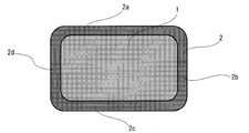
- FIG. 1 is a schematic cross-sectional view of one embodiment of the insulated wire of the present invention.
- FIG. 2 is a schematic cross-sectional view of another aspect of the insulated wire of the present invention.
- Fig.3 (a) is a schematic diagram of the jig
- FIG.3 (b) is a schematic diagram of the longitudinal cross-section of a jig in the state which let the electric wire sample created in the Example pass through the jig.
- the insulated wire of the present invention has a thermoplastic resin layer on a rectangular conductor in which four corners in a cross section have a curvature radius r.
- the insulated wire according to the present invention has a thermoplastic resin layer on a rectangular conductor, the adhesion strength between the thermoplastic resin layer and the rectangular conductor with respect to a pair of opposite sides of the rectangular conductor, and the other of the rectangular conductor. The adhesion strength between the thermoplastic resin layer and the rectangular conductor with respect to a pair of opposite sides of the two is different.
- the adhesion strength between the thermoplastic resin layer and the flat conductor to the corner portion of the flat conductor is equal to the adhesion strength between the thermoplastic resin layer and the flat conductor to a pair of opposite sides of the flat conductor, and the flat angle.
- either adhesion strength may be the same, and preferably the smaller adhesion strength. .
- FIG. 1 shows a schematic cross-sectional view of an insulated wire having a substantially rectangular flat conductor as one embodiment of the present invention.
- the conductor is substantially rectangular
- the longer side of the two pairs of opposing sides may be referred to as the longer side
- the shorter side may be referred to as the shorter side.
- the embodiment of the insulated wire of the present invention will be described with reference to FIG. 1.
- FIG. 1 shows that the contact state of the interface between the short side of the flat conductor 1 and the thermoplastic resin layer 2 is microscopically uneven. As a result, the adhesion strength is low.
- the adhesion strength of the thermoplastic resin layer 2 to the flat conductor 1 on the long side of the flat conductor 1 is greater than the adhesion strength of the thermoplastic resin layer 2 to the flat conductor 1 on the short side of the flat conductor 1.
- the adhesion strength of the right side surface portion 2b and the left side surface portion 2d of the thermoplastic resin layer 2 may be the same or different, but is preferably the same.
- the adhesion strength between the upper part 2a and the lower part 2c of the thermoplastic resin layer 2 may be the same or different from each other, but is preferably the same.
- thermoplasticity with respect to a pair of opposite sides “Adhesion strength between the resin layer and the rectangular conductor” means an average value of the adhesion strengths at two opposing sides.
- FIG. 2 is a schematic cross-sectional view of an insulated wire having a substantially rectangular flat conductor as one aspect of the present invention different from FIG.
- the embodiment of the insulated wire of the present invention will be described with reference to FIG. 2.
- the adhesion strength of the thermoplastic resin layer 2 on the long side of the flat conductor 1 with the flat conductor 1 is the thermoplastic resin on the short side of the flat conductor 1.
- the adhesion strength of the layer 2 to the rectangular conductor 1 is made smaller. Except for the magnitude relationship of the adhesion strength, it is the same as FIG.
- the conductors will be described in order.
- a conductor used for this invention what is normally used with an insulated wire can be used.
- a conductor is composed of a metal having conductivity, and the material thereof may be any material having conductivity. Examples thereof include aluminum or an aluminum alloy, or copper or a copper alloy.
- the flat conductor is made of an aluminum alloy, a 1000 series alloy having a low strength but a high aluminum ratio, an Al—Mg—Si alloy, for example, a 6101 alloy of a 6000 series aluminum alloy can be used.
- Aluminum or aluminum alloy has a conductivity of about 2/3 that of copper or copper alloy. However, since the specific gravity is about 1/3, the coil can be reduced in weight, which can contribute to a reduction in vehicle weight and fuel consumption.
- the conductor used in the present invention is preferably a copper wire, more preferably a low oxygen copper having an oxygen content of 30 ppm or less, more preferably a low oxygen copper or oxygen-free copper conductor having a oxygen content of 20 ppm or less. If the oxygen content is 30 ppm or less, when the conductor is melted with heat to prevent welding, voids due to oxygen contained in the welded portion are not generated, and the electrical resistance of the welded portion is prevented from deteriorating. The strength of the welded portion can be maintained.
- the conductor used in the present invention has a flat cross-sectional shape.
- a rectangular conductor has a higher space factor with respect to the stator slot during winding than a circular conductor. Therefore, it is preferable for such applications.
- the flat rectangular conductor preferably has a shape with chamfers (curvature radius r) at the four corners as shown in FIGS. 1 and 2 in terms of suppressing partial discharge from the corner.
- the radius of curvature r is preferably 0.6 mm or less, and more preferably in the range of 0.2 to 0.4 mm.
- the size of the cross section of the conductor is not particularly limited, but the length of a pair of opposing sides is preferably 1 to 5 mm, and more preferably 1.4 to 4.0 mm.
- the length of the other pair of opposing sides is preferably 0.4 to 3.0 mm, more preferably 0.5 to 2.5 mm.
- the ratio between the length of one pair of opposing sides and the thickness of the other pair of opposing sides is preferably 1: 1 to 4: 1.
- thermoplastic resin layer In the present invention, at least one thermoplastic resin layer made of a thermoplastic resin is provided on a rectangular conductor.
- thermoplastic resin that can be used for the thermoplastic resin layer
- polyamide (PA) nylon
- polyacetal (POM) polycarbonate
- PC polyphenylene ether (including modified polyphenylene ether)
- PBT polybutylene terephthalate
- PET polyethylene terephthalate
- PEN polyethylene naphthalate
- PSF polysulfone
- PES polyethersulfone
- PPS polyphenylene sulfide
- Polyarylate U polymer
- PAEK Tetrafluoroethylene / ethylene copolymer
- EFE Tetrafluoroethylene / ethylene copolymer
- PEEEK luketone
- PFA tetrafluoroethylene / perfluoroalkyl vinyl ether copolymer
- PTFE polytetrafluoroethylene
- polyphenylene sulfide PPS
- polyether ketone ketone PEKK
- polyaryl ether ketone PAEK
- modified PEEK polyether ether ketone
- PEEK polyether ether ketone
- thermoplastic resins may be used individually by 1 type, and may be used in combination of 2 or more type. Further, the resin used is not limited by the resin name shown above, and it is needless to say that any resin other than those listed above can be used as long as it is superior in performance to those resins.
- thermoplastic resins are general-purpose engineering plastics such as polyamide (PA), polyacetal (POM), polybutylene terephthalate (PBT), polyethylene terephthalate (PET), polyphenylene sulfide (PPS), ultra high molecular weight polyethylene, and the like.
- PA polyamide
- POM polyacetal
- PBT polybutylene terephthalate
- PET polyethylene terephthalate
- PPS polyphenylene sulfide
- ultra high molecular weight polyethylene and the like.
- Polyether ether ketone PEEK
- PEK polyether ketone
- PAEK polyaryl ether ketone
- PEKK polyaryl ether ketone
- TPI thermoplastic polyimide resin
- thermoplastic resin that can be used for the thermoplastic resin layer
- specific examples of the thermoplastic resin that can be used for the thermoplastic resin layer include, for example, PEEK381G (trade name) manufactured by Victrex Japan as PEEK, and AvaSpire AV manufactured by Solvay as modified PEEK. -650 (trade name) or AV-651 (trade name), Aurum PL450C (trade name) manufactured by Mitsui Chemicals as TPI, Durafide 0220A9 (trade name) manufactured by Polyplastics as PPS, or PPS manufactured by DIC FZ-2100 (trade name), made by Idemitsu Kosan Co., Ltd.
- the resin used for the thermoplastic resin layer is preferably a crystalline thermoplastic resin in view of heat aging characteristics and solvent resistance, and among them, PEEK, PPS, and TPI are particularly preferable.
- crystallinity refers to a property of having a crystal structure regularly arranged in at least a part of a polymer chain in an environment convenient for crystallization.
- amorphous means maintaining an amorphous state having almost no crystal structure, and means a characteristic that a polymer chain is in a random state upon curing.
- thermoplastic resin to be used may be used individually by 1 type, and 2 or more types may be mixed and used for it.
- the thermoplastic resin has a plurality of layers, different thermoplastic resins may be used in each layer, and the thermoplastic resins may be used in different mixing ratios.
- two types of thermoplastic resins are used in combination, for example, they are polymer-alloyed and used as a compatible homogeneous mixture, or an incompatible blend is used in a compatible state using a compatibilizing agent. Can be used.
- the thickness of the thermoplastic resin layer is preferably 10 to 100 ⁇ m, and more preferably 20 to 50 ⁇ m. If the thermoplastic resin layer is too thick, it may not be peeled even if the adhesion strength is equal. Therefore, an effect can be expected especially at a thickness of 100 ⁇ m or less. On the other hand, if the thickness of the thermoplastic resin layer is too thin, the dielectric breakdown voltage is too low, which is not suitable for an insulated wire for coils.
- the raw material for obtaining the thermoplastic resin layer as long as it does not affect the properties, crystallization nucleating agent, crystallization accelerator, bubble nucleating agent, antioxidant, antistatic agent, ultraviolet light inhibitor, Various additives such as light stabilizers, fluorescent brighteners, pigments, dyes, compatibilizers, lubricants, reinforcing agents, flame retardants, crosslinking agents, crosslinking aids, plasticizers, thickeners, thickeners, and elastomers May be blended. Moreover, the layer which consists of resin containing these additives may be laminated
- the insulated wire of the present invention has a thermoplastic resin layer on a flat conductor, and adhesion strength between the thermoplastic resin layer and the flat conductor with respect to a pair of opposing sides of the flat conductor, The adhesion strength between the thermoplastic resin layer and the flat conductor with respect to the other pair of opposite sides of the flat conductor is different.
- the function and effect of the present invention will be described with reference to FIG. In FIG. 1, as described above, the adhesion strength of the thermoplastic resin layer 2 to the flat conductor 1 on the long side of the flat conductor 1 is greater than the adhesion strength of the thermoplastic resin layer 2 to the flat conductor 1 on the short side of the flat conductor 1. Is also getting bigger.
- Such an insulated wire of the present invention is such that when the right side surface portion 2b and the left side surface portion 2d of the thermoplastic resin layer 2 are subjected to a shearing force during coil processing, the performance of the insulated wire is not affected immediately below the insulating coating layer. Since the minute gaps are generated and shifted, the insulated wire of the present invention shown in FIG. 1 can suppress deformation exceeding the breaking elongation of the thermoplastic resin layer 2 and prevent the insulation coating layer from peeling or cracking. .
- the insulated wire of the present invention unlike the above “void”, when “peeling” occurs, the performance as an insulated wire deteriorates so that it cannot be used practically.
- the adhesion strength between the thermoplastic resin layer and the flat conductor with respect to the long side is different from the adhesion strength between the thermoplastic resin layer and the flat conductor with respect to the short side of the flat conductor. Whichever is larger.
- the adhesion strength between the thermoplastic resin layer and the flat conductor on a pair of opposite sides of the flat conductor, and the adhesion strength between the thermoplastic resin layer and the flat conductor on another pair of opposite sides of the flat conductor Is preferably 5 gf / mm to 100 gf / mm, more preferably 10 gf / mm to 50 gf / mm, and particularly preferably 20 gf / mm to 40 gf / mm.
- the adhesion strength between the thermoplastic resin layer and the flat conductor with respect to a pair of opposing sides of the flat conductor is not particularly limited, but is preferably in the range of 5 gf / mm to 120 gf / mm. More preferably, it is in the range of ⁇ 100 gf / mm.
- the adhesion strength between the thermoplastic resin layer and the flat conductor with respect to the other pair of opposite sides of the flat conductor is not particularly limited, but is preferably in the range of 5 gf / mm to 120 gf / mm. More preferably, it is in the range of ⁇ 100 gf / mm. From the viewpoint of absorbing deformation exceeding the elongation at break of the thermoplastic resin layer, the difference in adhesion strength and the adhesion strength are preferably within the above ranges. A method for measuring the adhesion strength will be described later.
- the production method of the insulated wire is not particularly limited as long as the adhesion strength can satisfy the provisions of the present invention, and examples thereof include a production method by the following control.
- the flat conductor is heated by passing a heating wire through a tube provided inside.
- a tube having a rectangular cross section
- the distance between the pair of opposing sides of the flat conductor and the heating wire is different from the distance between the other pair of opposing sides of the flat conductor and the heating wire.
- the surface temperature of the pair of opposing sides of the rectangular conductor can be made different from the surface temperature of the other pair of opposing sides of the rectangular conductor.
- the flat conductor whose surface temperature has been adjusted is extruded and coated with a thermoplastic resin, whereby the adhesion strength to one pair of opposite sides of the flat conductor and the adhesion strength to the other pair of opposite sides of the flat conductor are
- the insulated wire of the present invention can be used in fields requiring voltage resistance and heat resistance, such as various electric devices (also referred to as electronic devices).
- the insulated wire of the present invention is coiled and used for a motor, a transformer, etc., and can constitute a high-performance electric device.
- it is suitably used as a winding for a drive motor of HV (hybrid car) or EV (electric car).
- HV hybrid car
- EV electric car
- Example 1 The insulated wire shown in FIG. 2 was manufactured.
- the rectangular conductor was heated using a tube having a rectangular cross section with heating wires inside so that the temperature of the short side surface of the flat conductor was higher than the temperature of the long side surface of the flat conductor.
- Adhesion strength of the thermoplastic resin layer 2 to the long side of the rectangular conductor is obtained by extrusion-coating polyether ether ketone (PEEK) (trade name: PEEK381G, manufactured by Victorex Japan), which is a thermoplastic resin, on the rectangular conductor.
- PEEK polyether ether ketone
- the insulated wire which consists of PEEK covering conductors smaller than the adhesive strength with respect to the short side of the flat conductor of the thermoplastic resin layer 2 was obtained.
- the thickness of the PEEK coating layer was 0.03 mm.
- the adhesion strength values of the right side surface portion 22b and the left side surface portion 22d of the thermoplastic resin layer 2 with respect to the short side of the rectangular conductor are the same, and the upper portion 22a and the lower portion 22c of the thermoplastic resin layer 2 with respect to the long side of the rectangular conductor are the same.
- the adhesion strength was also the same value.
- the adhesion strength of the thermoplastic resin layer 2 to the corner portion of the flat conductor was the same as the adhesion strength of the upper portion 22a of the thermoplastic resin layer 2 to the long side of the flat conductor. A method for measuring the adhesion strength will be described later.
- the adhesive strength between the thermoplastic resin layer, the thermoplastic resin layer and the rectangular conductor with respect to the long side of the rectangular conductor, and the adhesive strength between the thermoplastic resin layer and the rectangular conductor with respect to the short side of the rectangular conductor are as shown in Table 1 below. Except that, the insulated wire shown in FIG. 1 or FIG. 2 made of a thermoplastic resin-coated conductor was obtained in the same manner as in Example 1.
- the adhesion strength values of the right side surface portion 2b and the left side surface portion 2d of the thermoplastic resin layer 2 with respect to the short side of the flat conductor are the same, and the heat with respect to the long side of the flat conductor is the same.
- the adhesion strength between the upper part 2a and the lower part 2c of the plastic resin layer 2 was also the same value.
- the adhesion strength of the thermoplastic resin layer 2 to the corner portion of the flat conductor was the same as the adhesion strength of the right side surface portion 2b of the thermoplastic resin layer 2 to the short side of the flat conductor.
- the values of the adhesion strength of the right side surface portion 22b and the left side surface portion 22d of the thermoplastic resin layer 2 with respect to the short side of the flat conductor are the same, and the heat with respect to the long side of the flat conductor is the same.
- the adhesion strength between the upper part 22a and the lower part 22c of the plastic resin layer 2 was also the same value.
- the adhesion strength of the thermoplastic resin layer 2 to the corner portion of the flat conductor was the same as the adhesion strength of the upper portion 22a of the thermoplastic resin layer 2 to the long side of the flat conductor.
- the wire sample having a length of 400 mm cut out from the insulated wire prepared in each of the examples and comparative examples is passed through the hollow jig 3a side as shown in FIG. 3A, and one end of the wire sample from the jig 3c side.
- a tensile tester manufactured by Shimadzu Corporation, apparatus name “Autograph AG-X” so that the 3c side of the jig was down.
- a tensile tester manufactured by Shimadzu Corporation was made so that the wire sample was passed from the jig 3a side and one end of the wire sample was 150 mm from the jig 3c side, and the jig 3d side was down.
- the end of the 3c side of the wire sample coming out from the 3c side of the jig is pulled parallel to 3b in the direction of 3a to 3c at 100 mm / min to bring the wire sample and the jig into contact with each other. Observed whether or not.
- PEEK PEEK381G (trade name) manufactured by Victorex Japan
- PPS Polyplastics Durafide 0220A9 (trade name)
- TPI Aurum PL450C (trade name) manufactured by Mitsui Chemicals
- PES Sumika Excel 3600G (trade name) manufactured by Sumitomo Chemical Co., Ltd.
- PEI Ultem 1000 (trade name) manufactured by Subic Innovative Plastics PET: TR-8550T1 (trade name) manufactured by Teijin Chemicals
- the insulated wires of Examples 1 to 19 were acceptable in the wire pull-out test as described above, and were excellent in solvent resistance and heat aging characteristics.
- the insulated wires of Examples 20 to 22 were inferior in either the solvent resistance or the heat aging characteristics, but the results of the wire pull-out test were acceptable.
- the insulated wire of the present invention can be preferably applied to electric and electronic devices such as coils, particularly motor coils.
Landscapes
- Chemical & Material Sciences (AREA)
- Physics & Mathematics (AREA)
- Spectroscopy & Molecular Physics (AREA)
- Chemical Kinetics & Catalysis (AREA)
- Engineering & Computer Science (AREA)
- Life Sciences & Earth Sciences (AREA)
- Materials Engineering (AREA)
- Wood Science & Technology (AREA)
- Organic Chemistry (AREA)
- Power Engineering (AREA)
- Organic Insulating Materials (AREA)
- Insulation, Fastening Of Motor, Generator Windings (AREA)
- Insulated Conductors (AREA)
- Coils Or Transformers For Communication (AREA)
- Coils Of Transformers For General Uses (AREA)
Abstract
平角導体上に熱可塑性樹脂層を有し、該平角導体の1対の対向する辺に対する該熱可塑性樹脂層と該平角導体との密着強度と、該平角導体の他の1対の対向する辺に対する該熱可塑性樹脂層と該平角導体との密着強度とが互いに異なる絶縁電線。
Description
本発明は、絶縁電線およびコイルに関する。
モーターや変圧器に代表される電気機器は近年、機器の小型化及び高性能化が進展している。そこで、絶縁電線を巻線加工(コイル加工)して、電線を非常に狭い部分へ押しこんで使用する様な使い方が多く見られるようになった。具体的には、絶縁電線をコイル加工した巻線をステータースロット中に何本入れられるかにより、そのモーターなどの回転機の性能が決定するといっても過言ではない。その結果、ステータースロット断面積に対する導体の断面積の比率(占積率)の向上に対する要求が非常に高まっている。
占積率を向上させる手段として、断面が略矩形状の平角導体(以下、単に「平角導体」または「導体」という。)が使用されている。平角導体を用いて小型のコイルを作製する場合、占積率を向上させるため、導体のコーナー部の曲率半径が小さい絶縁電線をエッジワイズに小径のコアに巻線加工することにより小型のコイルを作製する。このようなエッジワイズ巻きコイルでは、絶縁電線にかかる負荷が非常に大きい。そのため、絶縁電線の機械的特性のさらなる向上が求められる。
絶縁電線の機械的特性を向上させる手段として、導体と絶縁被覆との密着性を向上させる試みがなされている。例えば、特許文献1には、予め加熱された導体に絶縁被覆を形成することで、絶縁被覆の導体に対する密着性を高め、力学的特性を向上させた絶縁電線が開示されている。また、特許文献2では、基材表面に粘弾性体層を有することにより被覆材と導体との密着性を向上させた被覆平角電線が開示されている。
しかしながら、上記特許文献1および2に記載の従来の技術では、導体の2つの対向する辺に対し、等しく導体との密着強度を向上させた絶縁被覆層が形成されている。このような絶縁被覆層を有する絶縁電線をコイル加工する際、絶縁電線どうしがが強く擦れ合うことにより、破断伸びを超える力がかかると、導体の全ての辺に等しい密着強度で絶縁被覆層が固定されていることが、絶縁被覆層に剥離や亀裂を生じさせる誘因となることを見い出した。
本発明は、絶縁被覆層の導体への密着性に優れ、かつ、コイルに加工する際に絶縁被覆層の剥離や亀裂が抑制される絶縁電線および該絶縁電線を用いたコイルを提供することを目的とする。
本発明は、絶縁被覆層の導体への密着性に優れ、かつ、コイルに加工する際に絶縁被覆層の剥離や亀裂が抑制される絶縁電線および該絶縁電線を用いたコイルを提供することを目的とする。
本発明者らは、上記の従来技術が有する問題を解決するため鋭意検討した結果、平角導体を用い、該平角導体の1対の対向する辺に対する絶縁被覆層と該平角導体との密着強度と、該平角導体の他の1対の対向する辺に対する絶縁被覆層と該平角導体との密着強度とを特定の関係に設定することにより、絶縁電線をコイルに加工する際に絶縁被覆の剥離や割れが発生するのを抑制できるという知見を得た。本発明は、この知見に基づきなされたものである。
すなわち、本発明の上記課題は、以下の手段によって達成された。
(1)平角導体上に熱可塑性樹脂層を有し、該平角導体の1対の対向する辺に対する該熱可塑性樹脂層と該平角導体との密着強度と、該平角導体の他の1対の対向する辺に対する該熱可塑性樹脂層と該平角導体との密着強度とが互いに異なる絶縁電線。
(2)前記平角導体の1対の対向する辺に対する前記熱可塑性樹脂層と前記平角導体との密着強度と、前記平角導体の他の1対の対向する辺に対する前記熱可塑性樹脂層と前記平角導体との密着強度との差が5gf/mm~100gf/mmであることを特徴とする(1)に記載の絶縁電線。
(3)前記密着強度の差が10gf/mm~50gf/mmであることを特徴とする(1)または(2)に記載の絶縁電線。
(4)前記熱可塑性樹脂層を構成する熱可塑性樹脂が、ポリエーテルエーテルケトン、ポリエーテルケトンケトン、ポリケトン、ポリフェニレンサルファイドおよび熱可塑性ポリイミドからなる群から選択される少なくとも1種であることを特徴とする(1)~(3)のいずれか1項に記載の絶縁電線。
(5)前記平角導体が、銅、無酸素銅および銅合金からなることを特徴とする(1)~(4)のいずれか1項に記載の絶縁電線。
(6)前記(1)~(5)のいずれか1項に記載の絶縁電線が、巻線加工されたことを特徴とするコイル。
(1)平角導体上に熱可塑性樹脂層を有し、該平角導体の1対の対向する辺に対する該熱可塑性樹脂層と該平角導体との密着強度と、該平角導体の他の1対の対向する辺に対する該熱可塑性樹脂層と該平角導体との密着強度とが互いに異なる絶縁電線。
(2)前記平角導体の1対の対向する辺に対する前記熱可塑性樹脂層と前記平角導体との密着強度と、前記平角導体の他の1対の対向する辺に対する前記熱可塑性樹脂層と前記平角導体との密着強度との差が5gf/mm~100gf/mmであることを特徴とする(1)に記載の絶縁電線。
(3)前記密着強度の差が10gf/mm~50gf/mmであることを特徴とする(1)または(2)に記載の絶縁電線。
(4)前記熱可塑性樹脂層を構成する熱可塑性樹脂が、ポリエーテルエーテルケトン、ポリエーテルケトンケトン、ポリケトン、ポリフェニレンサルファイドおよび熱可塑性ポリイミドからなる群から選択される少なくとも1種であることを特徴とする(1)~(3)のいずれか1項に記載の絶縁電線。
(5)前記平角導体が、銅、無酸素銅および銅合金からなることを特徴とする(1)~(4)のいずれか1項に記載の絶縁電線。
(6)前記(1)~(5)のいずれか1項に記載の絶縁電線が、巻線加工されたことを特徴とするコイル。
本発明の説明において、「~」を用いて表される数値範囲は、「~」の前後に記載される数値を下限値及び上限値として含む範囲を意味する。
また、本発明の絶縁電線において、導体の「辺」とは後述の曲率半径を有する導体のコーナー部以外の辺の部分を意味する。
また、本発明の絶縁電線において、「導体のコーナー部」とは、所定の曲率半径で形成された導体の曲部を意味する。
また、本発明の絶縁電線において、「平角導体」とは、横断面がコーナー部に後述の曲率半径を有する略長方形の導体および横断面がコーナー部に後述の曲率半径を有する略正方形の導体の両方を含む意味である。
また、本発明の絶縁電線において、導体の「辺」とは後述の曲率半径を有する導体のコーナー部以外の辺の部分を意味する。
また、本発明の絶縁電線において、「導体のコーナー部」とは、所定の曲率半径で形成された導体の曲部を意味する。
また、本発明の絶縁電線において、「平角導体」とは、横断面がコーナー部に後述の曲率半径を有する略長方形の導体および横断面がコーナー部に後述の曲率半径を有する略正方形の導体の両方を含む意味である。
本発明の絶縁電線は、絶縁被覆層の導体への密着性に優れ、コイルに加工する際に絶縁被覆層の剥離や割れが抑制される。また、前記本発明の絶縁電線を巻線加工して作成した本発明のコイルは、巻線加工時の曲げ加工に起因する絶縁被覆層の剥離や割れが防止される。
本発明の上記及び他の特徴及び利点は、適宜添付の図面を参照して、下記の記載からより明らかになるであろう。
本発明の上記及び他の特徴及び利点は、適宜添付の図面を参照して、下記の記載からより明らかになるであろう。
<<絶縁電線>>
本発明の絶縁電線は、断面における4つのコーナー部が曲率半径rを有する平角導体上に、熱可塑性樹脂層を有する。本発明の絶縁電線は、平角導体上に熱可塑性樹脂層を有し、該平角導体の1対の対向する辺に対する該熱可塑性樹脂層と該平角導体との密着強度と、該平角導体の他の1対の対向する辺に対する該熱可塑性樹脂層と該平角導体との密着強度が異なる。
なお、平角導体のコーナー部に対する熱可塑性樹脂層と該平角導体との密着強度は、該平角導体の1対の対向する辺に対する該熱可塑性樹脂層と該平角導体との密着強度と、該平角導体の他の1対の対向する辺に対する熱可塑性樹脂層と該平角導体との密着強度のうち、どちらの密着強度と同じであってもよく、小さい方の密着強度と同じであることが好ましい。
本発明の絶縁電線は、断面における4つのコーナー部が曲率半径rを有する平角導体上に、熱可塑性樹脂層を有する。本発明の絶縁電線は、平角導体上に熱可塑性樹脂層を有し、該平角導体の1対の対向する辺に対する該熱可塑性樹脂層と該平角導体との密着強度と、該平角導体の他の1対の対向する辺に対する該熱可塑性樹脂層と該平角導体との密着強度が異なる。
なお、平角導体のコーナー部に対する熱可塑性樹脂層と該平角導体との密着強度は、該平角導体の1対の対向する辺に対する該熱可塑性樹脂層と該平角導体との密着強度と、該平角導体の他の1対の対向する辺に対する熱可塑性樹脂層と該平角導体との密着強度のうち、どちらの密着強度と同じであってもよく、小さい方の密着強度と同じであることが好ましい。
図1は、本発明の一態様として、略長方形の平角導体を有する絶縁電線の模式的な断面図を表している。
以下、導体が略長方形である場合、2組の1対の対向する辺のうち、長い方を長辺、短い方を短辺ということもある。
図1を参照して本発明の絶縁電線の実施態様を説明すると、図1は、平角導体1の短辺と熱可塑性樹脂層2との界面の密着状態がミクロ的に不均一であることなどにより、密着強度が低くなっている。平角導体1の長辺における熱可塑性樹脂層2の平角導体1との密着強度が、平角導体1の短辺における熱可塑性樹脂層2の平角導体1に対する密着強度よりも大きくなっている。このように密着強度を制御した絶縁電線の作製方法については後述する。
以下、導体が略長方形である場合、2組の1対の対向する辺のうち、長い方を長辺、短い方を短辺ということもある。
図1を参照して本発明の絶縁電線の実施態様を説明すると、図1は、平角導体1の短辺と熱可塑性樹脂層2との界面の密着状態がミクロ的に不均一であることなどにより、密着強度が低くなっている。平角導体1の長辺における熱可塑性樹脂層2の平角導体1との密着強度が、平角導体1の短辺における熱可塑性樹脂層2の平角導体1に対する密着強度よりも大きくなっている。このように密着強度を制御した絶縁電線の作製方法については後述する。
図1において、熱可塑性樹脂層2の右側面部2bと左側面部2dの密着強度は互いに同じでも異なってもよいが、同じであることが好ましい。また、熱可塑性樹脂層2の上部2aと下部2cの密着強度は互いに同じでも異なってもよいが、同じであることが好ましい。
熱可塑性樹脂層2の右側面部2bと左側面部2dの密着強度が異なり、および/または熱可塑性樹脂層2の上部2aと下部2cの密着強度が異なる場合、「1対の対向する辺に対する熱可塑性樹脂層と平角導体との密着強度」とは対向する2つの辺における密着強度の平均値をいう。
熱可塑性樹脂層2の右側面部2bと左側面部2dの密着強度が異なり、および/または熱可塑性樹脂層2の上部2aと下部2cの密着強度が異なる場合、「1対の対向する辺に対する熱可塑性樹脂層と平角導体との密着強度」とは対向する2つの辺における密着強度の平均値をいう。
図2は、図1とは別の本発明の一態様として、略長方形の平角導体を有する絶縁電線の模式的な断面図を表している。
図2を参照して本発明の絶縁電線の実施態様を説明すると、平角導体1の長辺における熱可塑性樹脂層2の平角導体1との密着強度が、平角導体1の短辺における熱可塑性樹脂層2の平角導体1に対する密着強度よりも小さくする。この密着強度の大小関係以外は図1と同様である。
以下、導体から順に説明する。
図2を参照して本発明の絶縁電線の実施態様を説明すると、平角導体1の長辺における熱可塑性樹脂層2の平角導体1との密着強度が、平角導体1の短辺における熱可塑性樹脂層2の平角導体1に対する密着強度よりも小さくする。この密着強度の大小関係以外は図1と同様である。
以下、導体から順に説明する。
<導体>
本発明に用いる導体としては、通常、絶縁電線で用いられているものを使用することができる。このような導体としては、導電性を有する金属で構成され、その材質は導電性を有するものであればよく、例えばアルミニウムもしくはアルミニウム合金、又は銅もしくは銅合金が挙げられる。平角導体がアルミニウム合金で構成される場合、低強度ではあるがアルミニウム比率が高い1000系や、Al-Mg-Si系合金、例えば6000系アルミニウム合金の6101合金が挙げられる。アルミニウム又はアルミニウム合金は、その導電率が銅又は銅合金の約2/3である。しかし、比重は約1/3であることから、コイルを軽量化することができ、車両の軽量化、燃費向上に寄与することができる。平角導体が銅又は銅合金で構成される場合、一般的に絶縁電線で用いられているものを使用することができる。本発明に用いる導体として好ましくは、銅線であり、より好ましくは、酸素含有量が30ppm以下の低酸素銅、さらに好ましくは20ppm以下の低酸素銅または無酸素銅の導体である。酸素含有量が30ppm以下であれば、導体を溶接するために熱で溶融させた場合、溶接部分に含有酸素に起因するボイドの発生がなく、溶接部分の電気抵抗が悪化することを防止するとともに溶接部分の強度を保持することができる。
本発明に用いる導体としては、通常、絶縁電線で用いられているものを使用することができる。このような導体としては、導電性を有する金属で構成され、その材質は導電性を有するものであればよく、例えばアルミニウムもしくはアルミニウム合金、又は銅もしくは銅合金が挙げられる。平角導体がアルミニウム合金で構成される場合、低強度ではあるがアルミニウム比率が高い1000系や、Al-Mg-Si系合金、例えば6000系アルミニウム合金の6101合金が挙げられる。アルミニウム又はアルミニウム合金は、その導電率が銅又は銅合金の約2/3である。しかし、比重は約1/3であることから、コイルを軽量化することができ、車両の軽量化、燃費向上に寄与することができる。平角導体が銅又は銅合金で構成される場合、一般的に絶縁電線で用いられているものを使用することができる。本発明に用いる導体として好ましくは、銅線であり、より好ましくは、酸素含有量が30ppm以下の低酸素銅、さらに好ましくは20ppm以下の低酸素銅または無酸素銅の導体である。酸素含有量が30ppm以下であれば、導体を溶接するために熱で溶融させた場合、溶接部分に含有酸素に起因するボイドの発生がなく、溶接部分の電気抵抗が悪化することを防止するとともに溶接部分の強度を保持することができる。
本発明で使用する導体は、断面形状が、平角形状である。平角形状の導体は円形のものと比較し、巻線時に、ステータースロットに対する占積率が高い。従って、このような用途に好ましい。
平角形状の導体は、角部からの部分放電を抑制するという点において、図1および2に示すように4隅に面取り(曲率半径r)を設けた形状であることが好ましい。曲率半径rは、0.6mm以下が好ましく、0.2~0.4mmの範囲がより好ましい。
導体の断面の大きさは、特に限定はないが、1対の対向する辺の長さは1~5mmが好ましく、1.4~4.0mmがより好ましい。一方、他の1対の対向する辺の長さは0.4~3.0mmが好ましく、0.5~2.5mmがより好ましい。1対の対向する辺の長さと厚み他の1対の対向する辺の長さの割合は、1:1~4:1が好ましい。
平角形状の導体は、角部からの部分放電を抑制するという点において、図1および2に示すように4隅に面取り(曲率半径r)を設けた形状であることが好ましい。曲率半径rは、0.6mm以下が好ましく、0.2~0.4mmの範囲がより好ましい。
導体の断面の大きさは、特に限定はないが、1対の対向する辺の長さは1~5mmが好ましく、1.4~4.0mmがより好ましい。一方、他の1対の対向する辺の長さは0.4~3.0mmが好ましく、0.5~2.5mmがより好ましい。1対の対向する辺の長さと厚み他の1対の対向する辺の長さの割合は、1:1~4:1が好ましい。
<熱可塑性樹脂層>
本発明では、平角導体上に熱可塑性樹脂で構成される熱可塑性樹脂層を少なくとも1層有する。
本発明では、平角導体上に熱可塑性樹脂で構成される熱可塑性樹脂層を少なくとも1層有する。
本発明の絶縁電線において、熱可塑性樹脂層に用いることができる熱可塑性樹脂としては、ポリアミド(PA)(ナイロン)、ポリアセタール(POM)、ポリカーボネート(PC)、ポリフェニレンエーテル(変性ポリフェニレンエーテルを含む)、ポリブチレンテレフタレート(PBT)、ポリエチレンテレフタレート(PET)、ポリエチレンナフタレート(PEN)、超高分子量ポリエチレン等の汎用エンジニアリングプラスチックの他、ポリスルホン(PSF)、ポリエーテルスルホン(PES)、ポリフェニレンスルフィド(PPS)、ポリアリレート(Uポリマー)、ポリエーテルケトン(PEK)、ポリアリールエーテルケトン(PAEK)、テトラフルオロエチレン・エチレン共重合体(ETFE)、ポリエーテルエーテルケトン(PEEK)、テトラフルオロエチレン・パーフルオロアルキルビニルエーテル共重合体(PFA)、ポリテトラフルオロエチレン(PTFE)、熱可塑性ポリイミド樹脂(TPI)、ポリアミドイミド(PAI)、液晶ポリエステル等のスーパーエンジニアリングプラスチック、さらに、ポリエチレンテレフタレート(PET)、ポリエチレンナフタレート(PEN)をベース樹脂とするポリマーアロイ、ABS/ポリカーボネート、ナイロン6,6、芳香族ポリアミド樹脂、ポリフェニレンエーテル/ナイロン6,6、ポリフェニレンエーテル/ポリスチレン、ポリブチレンテレフタレート/ポリカーボネート等の前記エンジニアリングプラスチックを含むポリマーアロイが挙げられる。本発明においては、耐熱性と耐ストレスクラック性の点において、ポリフェニレンスルフィド(PPS)、ポリエーテルケトンケトン(PEKK)、ポリアリールエーテルケトン(PAEK)(変性PEEKを含む)、ポリエーテルエーテルケトン(PEEK)を特に好ましく用いることができる。これらの熱可塑性樹脂は1種単独で用いても良く、また、2種以上を組み合わせて用いてもよい。また、上記に示した樹脂名によって使用樹脂が限定されるものではなく、先に列挙した樹脂以外にも、それらの樹脂より性能的に優れる樹脂であれば使用可能であるのは勿論である。
これらのうち結晶性熱可塑性樹脂は、例えば、ポリアミド(PA)、ポリアセタール(POM)、ポリブチレンテレフタレート(PBT)、ポリエチレンテレフタレート(PET)、ポリフェニレンスルフィド(PPS)、超高分子量ポリエチレン等の汎用エンジニアリングプラスチック、ポリエーテルエーテルケトン(PEEK)、ポリエーテルケトン(PEK)、ポリアリールエーテルケトン(PAEK)(変性PEEKを含む)、ポリエーテルケトンケトン(PEKK)および熱可塑性ポリイミド樹脂(TPI)が挙げられる。
本発明の絶縁電線において、熱可塑性樹脂層に用いることができる熱可塑性樹脂の具体例としては、例えば、PEEKとしてビクトレックスジャパン社製のPEEK381G(商品名)、変性PEEKとしてソルベイ社製のアバスパイアAV-650(商品名)またはAV-651(商品名)、TPIとして三井化学社製のオーラムPL450C(商品名)、PPSとしてポリプラスチックス社製のジュラファイド0220A9(商品名)またはDIC社製のPPS FZ-2100(商品名)、SPSとして出光興産株式会社製:ザレックS105(商品名)、PAとしてナイロン6,6(ユニチカ社製:FDK-1(商品名))、ナイロン4,6(ユニチカ株式会社製:F-5000(商品名)、ナイロン6,T(三井石油化学株式会社製:アーレンAE-420(商品名))、ナイロン9,T(クラレ株式会社製:ジェネスタN1006D(商品名))、PESとして住友化学株式会社製のスミカエクセル3600G(商品名)、PEIとしてサビックイノベーティブプラスチックス社製のウルテム1000(商品名)、PETとして帝人化成社製のTR-8550T1(商品名)等の市販品を挙げることができる。
なかでも、熱可塑性樹脂層に用いる樹脂は、耐熱老化特性および耐溶剤性を考慮すると結晶性の熱可塑性樹脂が好ましく、その中でもPEEK、PPS、TPIが特に好ましい。
なお、本明細書において、「結晶性」とは結晶化に好都合な環境下で、高分子の鎖の少なくとも一部に規則正しく配列された結晶組織を持つことができる特性をいう。これに対して、「非晶性」とはほとんど結晶構造を持たない無定形状態を保つことをいい、硬化時に高分子の鎖がランダムな状態になる特性をいう。
なお、使用する熱可塑性樹脂は、1種のみを単独で用いてもよく、2種以上を混合して使用してもよい。また、熱可塑性樹脂が複数層の場合、各層で互いに異なった熱可塑性樹脂を用いてもよく、さらに異なった混合比率で熱可塑性樹脂を使用してもよい。
2種の熱可塑性樹脂を混合して使用する場合は、例えば両者をポリマーアロイ化して相溶型の均一な混合物として使用するか、非相溶系のブレンドを、相溶化剤を用いて相溶状態を形成して使用することができる。
2種の熱可塑性樹脂を混合して使用する場合は、例えば両者をポリマーアロイ化して相溶型の均一な混合物として使用するか、非相溶系のブレンドを、相溶化剤を用いて相溶状態を形成して使用することができる。
本発明では、前記熱可塑性樹脂層の厚さは、10~100μmが好ましく、20~50μmがより好ましい。
前記熱可塑性樹脂層の厚さが厚すぎると、密着強度が同等でも剥離しない場合があるので特に100μm以下の厚みにおいて効果が期待できる。また前記熱可塑性樹脂層の厚さが薄すぎると、絶縁破壊電圧が低すぎる為コイル用絶縁電線には適さなない。
前記熱可塑性樹脂層の厚さが厚すぎると、密着強度が同等でも剥離しない場合があるので特に100μm以下の厚みにおいて効果が期待できる。また前記熱可塑性樹脂層の厚さが薄すぎると、絶縁破壊電圧が低すぎる為コイル用絶縁電線には適さなない。
本発明においては、特性に影響を及ぼさない範囲で、熱可塑性樹脂層を得る原料に、結晶化核剤、結晶化促進剤、気泡化核剤、酸化防止剤、帯電防止剤、紫外線防止剤、光安定剤、蛍光増白剤、顔料、染料、相溶化剤、滑剤、強化剤、難燃剤、架橋剤、架橋助剤、可塑剤、増粘剤、減粘剤、およびエラストマー等の各種添加剤を配合してもよい。また、得られる絶縁電線に、これらの添加剤を含有する樹脂からなる層を積層してもよいし、これらの添加剤を含有する塗料をコーティングしてもよい。
<密着強度>
上述のように、本発明の絶縁電線は、平角導体上に熱可塑性樹脂層を有し、該平角導体の1対の対向する辺に対する該熱可塑性樹脂層と該平角導体との密着強度と、該平角導体の他の1対の対向する辺に対する該熱可塑性樹脂層と該平角導体との密着強度とが異なる。以下、図1を参照して本発明の作用効果について説明する。
図1において、上述のとおり、平角導体1の長辺における熱可塑性樹脂層2の平角導体1との密着強度が、平角導体1の短辺における熱可塑性樹脂層2の平角導体1に対する密着強度よりも大きくなっている。このような本発明の絶縁電線は、コイル加工時に熱可塑性樹脂層2の右側面部2bと左側面部2dはずりの力がかかると絶縁被覆層直下に、絶縁電線の性能に影響を与えない程度の微小な空隙が発生してずれるため、図1に記載の本発明の絶縁電線は、熱可塑性樹脂層2の破断伸びを超える変形を吸収して絶縁被覆層に剥離や割れが生じるのを抑止できる。
ここで、本発明の絶縁電線において、上記「空隙」と異なり、「剥離」が発生すると実用上使用できない程絶縁電線としての性能が低下する。
なお、本発明において、平角導体が略長方形である場合、長辺に対する熱可塑性樹脂層と平角導体との密着強度が平角導体の短辺に対する熱可塑性樹脂層と平角導体との密着強度とが異なればよく、どちらが大きくてもよい。
上述のように、本発明の絶縁電線は、平角導体上に熱可塑性樹脂層を有し、該平角導体の1対の対向する辺に対する該熱可塑性樹脂層と該平角導体との密着強度と、該平角導体の他の1対の対向する辺に対する該熱可塑性樹脂層と該平角導体との密着強度とが異なる。以下、図1を参照して本発明の作用効果について説明する。
図1において、上述のとおり、平角導体1の長辺における熱可塑性樹脂層2の平角導体1との密着強度が、平角導体1の短辺における熱可塑性樹脂層2の平角導体1に対する密着強度よりも大きくなっている。このような本発明の絶縁電線は、コイル加工時に熱可塑性樹脂層2の右側面部2bと左側面部2dはずりの力がかかると絶縁被覆層直下に、絶縁電線の性能に影響を与えない程度の微小な空隙が発生してずれるため、図1に記載の本発明の絶縁電線は、熱可塑性樹脂層2の破断伸びを超える変形を吸収して絶縁被覆層に剥離や割れが生じるのを抑止できる。
ここで、本発明の絶縁電線において、上記「空隙」と異なり、「剥離」が発生すると実用上使用できない程絶縁電線としての性能が低下する。
なお、本発明において、平角導体が略長方形である場合、長辺に対する熱可塑性樹脂層と平角導体との密着強度が平角導体の短辺に対する熱可塑性樹脂層と平角導体との密着強度とが異なればよく、どちらが大きくてもよい。
本発明において、平角導体の1対の対向する辺に対する熱可塑性樹脂層と平角導体との密着強度と、平角導体の他の1対の対向する辺に対する熱可塑性樹脂層と平角導体との密着強度との差は、5gf/mm~100gf/mmが好ましく、10gf/mm~50gf/mmがより好ましく、20gf/mm~40gf/mmが特に好ましい。
本発明において、平角導体の1対の対向する辺に対する熱可塑性樹脂層と平角導体との密着強度は特に制限されないが、5gf/mm~120gf/mmの範囲内にあることが好ましく、5gf/mm~100gf/mmの範囲内にあることがより好ましい。一方、平角導体の他の1対の対向する辺に対する熱可塑性樹脂層と平角導体との密着強度は特に制限されないが、5gf/mm~120gf/mmの範囲内にあることが好ましく、5gf/mm~100gf/mmの範囲内にあることがより好ましい。
熱可塑性樹脂層の破断伸びを超える変形を吸収するという観点から、密着強度の差および密着強度が上記範囲内にあることが好ましい。
なお、密着強度の測定法は後述する。
熱可塑性樹脂層の破断伸びを超える変形を吸収するという観点から、密着強度の差および密着強度が上記範囲内にあることが好ましい。
なお、密着強度の測定法は後述する。
<<絶縁電線の作製方法>>
絶縁電線の作製方法は、密着強度が本発明の規定を満たすようにできるものであれば特に制限されないが、例えば、下記の制御による作製方法が挙げられる。
絶縁電線の作製方法は、密着強度が本発明の規定を満たすようにできるものであれば特に制限されないが、例えば、下記の制御による作製方法が挙げられる。
(1)導体の表面粗度の違いを利用した作製方法
レーザ又はプラズマ照射により、熱可塑性樹脂層との密着強度を小さくする方の平角導体の1対の対向する辺の表面に凹凸を設ける。凹凸を設けた後に熱可塑性樹脂を押出被覆することにより、凹凸を設けなかった平角導体の1対の対向する辺に対する密着強度が、凹凸を設けた平角導体の1対の対向する辺に対する密着強度よりも大きい絶縁電線を得ることができる。
(2)導体表面の温度の違いを利用した作製方法
予め加熱した平角導体に熱可塑性樹脂を押出し被覆することにより絶縁電線を作製する。
平角導体の加熱は、電熱線を内側に備えた管の中を通すことにより行う。例えば、横断面が長方形の管を用いることにより、平角導体の1対の対向する辺と電熱線との距離と、平角導体の他の1対の対向する辺と電熱線との距離は異なる。これらの距離が互いに異なることにより、平角導体の1対の対向する辺の表面温度と平角導体の他の1対の対向する辺の表面温度とを相違させることができる。このように表面温度が調節された平角導体に熱可塑性樹脂を押出し被覆することにより平角導体の1対の対向する辺に対する密着強度と、平角導体の他の1対の対向する辺に対する密着強度とが異なる絶縁電線を得ることができる。
レーザ又はプラズマ照射により、熱可塑性樹脂層との密着強度を小さくする方の平角導体の1対の対向する辺の表面に凹凸を設ける。凹凸を設けた後に熱可塑性樹脂を押出被覆することにより、凹凸を設けなかった平角導体の1対の対向する辺に対する密着強度が、凹凸を設けた平角導体の1対の対向する辺に対する密着強度よりも大きい絶縁電線を得ることができる。
(2)導体表面の温度の違いを利用した作製方法
予め加熱した平角導体に熱可塑性樹脂を押出し被覆することにより絶縁電線を作製する。
平角導体の加熱は、電熱線を内側に備えた管の中を通すことにより行う。例えば、横断面が長方形の管を用いることにより、平角導体の1対の対向する辺と電熱線との距離と、平角導体の他の1対の対向する辺と電熱線との距離は異なる。これらの距離が互いに異なることにより、平角導体の1対の対向する辺の表面温度と平角導体の他の1対の対向する辺の表面温度とを相違させることができる。このように表面温度が調節された平角導体に熱可塑性樹脂を押出し被覆することにより平角導体の1対の対向する辺に対する密着強度と、平角導体の他の1対の対向する辺に対する密着強度とが異なる絶縁電線を得ることができる。
本発明の絶縁電線は、前記特徴を有しているから、各種電気機器(電子機器ともいう。)等、耐電圧性や耐熱性を必要とする分野に利用可能である。例えば、本発明の絶縁電線はコイル加工してモーターやトランスなどに用いられ、高性能の電気機器を構成できる。特にHV(ハイブリッドカー)やEV(電気自動車)の駆動モーター用の巻線として好適に用いられる。このように、本発明によれば、上記の絶縁電線をコイル化して用いた、電気機器、特にHVおよびEVの駆動モーターを提供できる。なお、本発明の絶縁電線がモーターコイルに用いられる場合にはモーターコイル用絶縁電線とも称する。
以下に、本発明を実施例に基づいて、さらに詳細に説明するが、これらは本発明を制限するものではない。
[実施例1]
図2に示す絶縁電線を製造した。
導体1には断面平角(長辺3.0mm×短辺1.7mmで、四隅の面取りの曲率半径r=0.3mm)の平角導体(酸素含有量5ppmの銅)を用いた。
電熱線を内側に備えた横断面が長方形の管を用いて、平角導体の短辺の表面の温度が、平角導体の長辺の表面の温度より高くなるように平角導体を加熱した。
この平角導体に、熱可塑性樹脂であるポリエーテルエーテルケトン(PEEK)(商品名:PEEK381G、ビクトレックスジャパン社製)を押出し被覆することにより、熱可塑性樹脂層2の平角導体の長辺に対する密着強度が、熱可塑性樹脂層2の平角導体の短辺に対する密着強度よりも小さいPEEK被覆導体からなる絶縁電線を得た。
PEEK被覆層の厚みは0.03mmであった。また、平角導体の短辺に対する熱可塑性樹脂層2の右側面部22bと左側面部22dの密着強度の値は互いに同じであり、平角導体の長辺に対する熱可塑性樹脂層2の上部22aと下部22cの密着強度も互いに同じ値であった。また、平角導体のコーナー部に対する熱可塑性樹脂層2の密着強度は、平角導体の長辺に対する熱可塑性樹脂層2の上部22aの密着強度と同じであった。
なお、密着強度の測定方法は後述する。
図2に示す絶縁電線を製造した。
導体1には断面平角(長辺3.0mm×短辺1.7mmで、四隅の面取りの曲率半径r=0.3mm)の平角導体(酸素含有量5ppmの銅)を用いた。
電熱線を内側に備えた横断面が長方形の管を用いて、平角導体の短辺の表面の温度が、平角導体の長辺の表面の温度より高くなるように平角導体を加熱した。
この平角導体に、熱可塑性樹脂であるポリエーテルエーテルケトン(PEEK)(商品名:PEEK381G、ビクトレックスジャパン社製)を押出し被覆することにより、熱可塑性樹脂層2の平角導体の長辺に対する密着強度が、熱可塑性樹脂層2の平角導体の短辺に対する密着強度よりも小さいPEEK被覆導体からなる絶縁電線を得た。
PEEK被覆層の厚みは0.03mmであった。また、平角導体の短辺に対する熱可塑性樹脂層2の右側面部22bと左側面部22dの密着強度の値は互いに同じであり、平角導体の長辺に対する熱可塑性樹脂層2の上部22aと下部22cの密着強度も互いに同じ値であった。また、平角導体のコーナー部に対する熱可塑性樹脂層2の密着強度は、平角導体の長辺に対する熱可塑性樹脂層2の上部22aの密着強度と同じであった。
なお、密着強度の測定方法は後述する。
[実施例2~19、比較例1]
導体1として断面平角(長辺3.0mm×短辺1.7mmで、四隅の面取りの曲率半径r=0.3mm)の平角導体(酸素含有量5ppmの銅)を用いた。熱可塑性樹脂層、平角導体の長辺に対する熱可塑性樹脂層と平角導体との密着強度、平角導体の短辺に対する熱可塑性樹脂層と平角導体との密着強度を下記表1に記載されるようにした以外は、実施例1と同様にして、熱可塑性樹脂被覆導体からなる図1または図2に示す絶縁電線を得た。
なお、図1で表される絶縁電線おいて、平角導体の短辺に対する熱可塑性樹脂層2の右側面部2bと左側面部2dの密着強度の値は互いに同じであり、平角導体の長辺に対する熱可塑性樹脂層2の上部2aと下部2cの密着強度も互いに同じ値であった。また、平角導体のコーナー部に対する熱可塑性樹脂層2の密着強度は、平角導体の短辺に対する熱可塑性樹脂層2の右側面部2bの密着強度と同じであった。
導体1として断面平角(長辺3.0mm×短辺1.7mmで、四隅の面取りの曲率半径r=0.3mm)の平角導体(酸素含有量5ppmの銅)を用いた。熱可塑性樹脂層、平角導体の長辺に対する熱可塑性樹脂層と平角導体との密着強度、平角導体の短辺に対する熱可塑性樹脂層と平角導体との密着強度を下記表1に記載されるようにした以外は、実施例1と同様にして、熱可塑性樹脂被覆導体からなる図1または図2に示す絶縁電線を得た。
なお、図1で表される絶縁電線おいて、平角導体の短辺に対する熱可塑性樹脂層2の右側面部2bと左側面部2dの密着強度の値は互いに同じであり、平角導体の長辺に対する熱可塑性樹脂層2の上部2aと下部2cの密着強度も互いに同じ値であった。また、平角導体のコーナー部に対する熱可塑性樹脂層2の密着強度は、平角導体の短辺に対する熱可塑性樹脂層2の右側面部2bの密着強度と同じであった。
一方、図2で表される絶縁電線おいて、平角導体の短辺に対する熱可塑性樹脂層2の右側面部22bと左側面部22dの密着強度の値は互いに同じであり、平角導体の長辺に対する熱可塑性樹脂層2の上部22aと下部22cの密着強度も互いに同じ値であった。また、平角導体のコーナー部に対する熱可塑性樹脂層2の密着強度は、平角導体の長辺に対する熱可塑性樹脂層2の上部22aの密着強度と同じであった。
(密着強度の測定法)
熱可塑性樹脂層を一部剥離した絶縁電線を引張試験機(島津製作所社製、装置名「オートグラフAG-X」)にセットし、4mm/minの速度で熱可塑性樹脂層を上方へ引き剥がした(180°剥離)。その際に読み取った引張荷重を密着強度(gf/mm)とした。
熱可塑性樹脂層を一部剥離した絶縁電線を引張試験機(島津製作所社製、装置名「オートグラフAG-X」)にセットし、4mm/minの速度で熱可塑性樹脂層を上方へ引き剥がした(180°剥離)。その際に読み取った引張荷重を密着強度(gf/mm)とした。
上記のようにして作製した各絶縁電線に対して、電線引き抜き試験を行った。
-電線引き抜き試験(剥離および割れの評価)-
図3で示す内部が空洞のジグ内に各絶縁電線を通し、端部を持ち引き抜き、引き抜き後の各絶縁電線を目視で確認し、絶縁層に皮膜の剥離もしくは亀裂(割れ)が発生したか否かを目視で確認した。具体的な試験方法を以下に記載する。
図3で示す内部が空洞のジグ内に各絶縁電線を通し、端部を持ち引き抜き、引き抜き後の各絶縁電線を目視で確認し、絶縁層に皮膜の剥離もしくは亀裂(割れ)が発生したか否かを目視で確認した。具体的な試験方法を以下に記載する。
各実施例および比較例で作成した絶縁電線から切り出した長さ400mmの電線試料を図3(a)に示す内部が空洞のジグの3a側から通しジグの3c側から電線試料の一方の端部が150mm出た状態で、ジグの3c側が下になるように引張試験機(島津製作所社製、装置名「オートグラフAG-X」)にジグと一緒にセットした。ジグの3c側から出ている電線試料の3c側の端部を100mm/minで3aから3cの方向に3bと平行に引っ張り、電線試料とジグを接触(こすれ)させ、絶縁被覆層に剥離もしくは亀裂が発生したか否かを観察した。次に、3aを下にして、上記と同様にジグの3a側から150mm出た状態の電線試料の3a側の端部を引っ張り、電線試料とジグを接触させ、絶縁被覆層に剥離もしくは亀裂が発生したか否かを観察した。
さらに、電線試料をジグの3a側から通しジグの3c側から電線試料の一方の端部が150mm電線試料が出た状態で、ジグの3d側が下になるように引張試験機(島津製作所社製、装置名「オートグラフAG-X」)にジグと一緒にセットした。ジグの3c側から出ている電線試料の3c側の端部を100mm/minで3aから3cの方向に3bと平行に引っ張り、電線試料とジグを接触させ、絶縁被覆層に剥離もしくは亀裂が発生したか否かを観察した。次に、3bを下にして、上記と同様にジグの3a側から150mm出た状態の電線試料の3a側の端部を引っ張り、電線試料とジグを接触させ、絶縁被覆層に剥離もしくは亀裂が発生したか否かを観察した。
ここまでの工程を1回の引き抜き試験として、各電線試料につきこの引き抜き試験を4回繰り返し実施した。
さらに、電線試料をジグの3a側から通しジグの3c側から電線試料の一方の端部が150mm電線試料が出た状態で、ジグの3d側が下になるように引張試験機(島津製作所社製、装置名「オートグラフAG-X」)にジグと一緒にセットした。ジグの3c側から出ている電線試料の3c側の端部を100mm/minで3aから3cの方向に3bと平行に引っ張り、電線試料とジグを接触させ、絶縁被覆層に剥離もしくは亀裂が発生したか否かを観察した。次に、3bを下にして、上記と同様にジグの3a側から150mm出た状態の電線試料の3a側の端部を引っ張り、電線試料とジグを接触させ、絶縁被覆層に剥離もしくは亀裂が発生したか否かを観察した。
ここまでの工程を1回の引き抜き試験として、各電線試料につきこの引き抜き試験を4回繰り返し実施した。
引き抜き試験を4回行っても剥離もしくは割れのいずれも確認できなかった場合を「A」、3回引き抜きを行っても剥離もしくは割れのいずれも確認できなかった場合を「B」、2回引き抜きを行っても剥離もしくは割れのいずれも確認できなかった場合を「C」、1回引き抜きを行っても剥離もしくは割れのいずれも確認できなかった場合を「D」、1回引き抜きを行って剥離もしくは割れが確認できた場合を「E」とした。
「A」、「B」、「C」が合格であり、「D」、「E」が不合格である。
得られた結果を下記表1~3に示す。
「A」、「B」、「C」が合格であり、「D」、「E」が不合格である。
得られた結果を下記表1~3に示す。
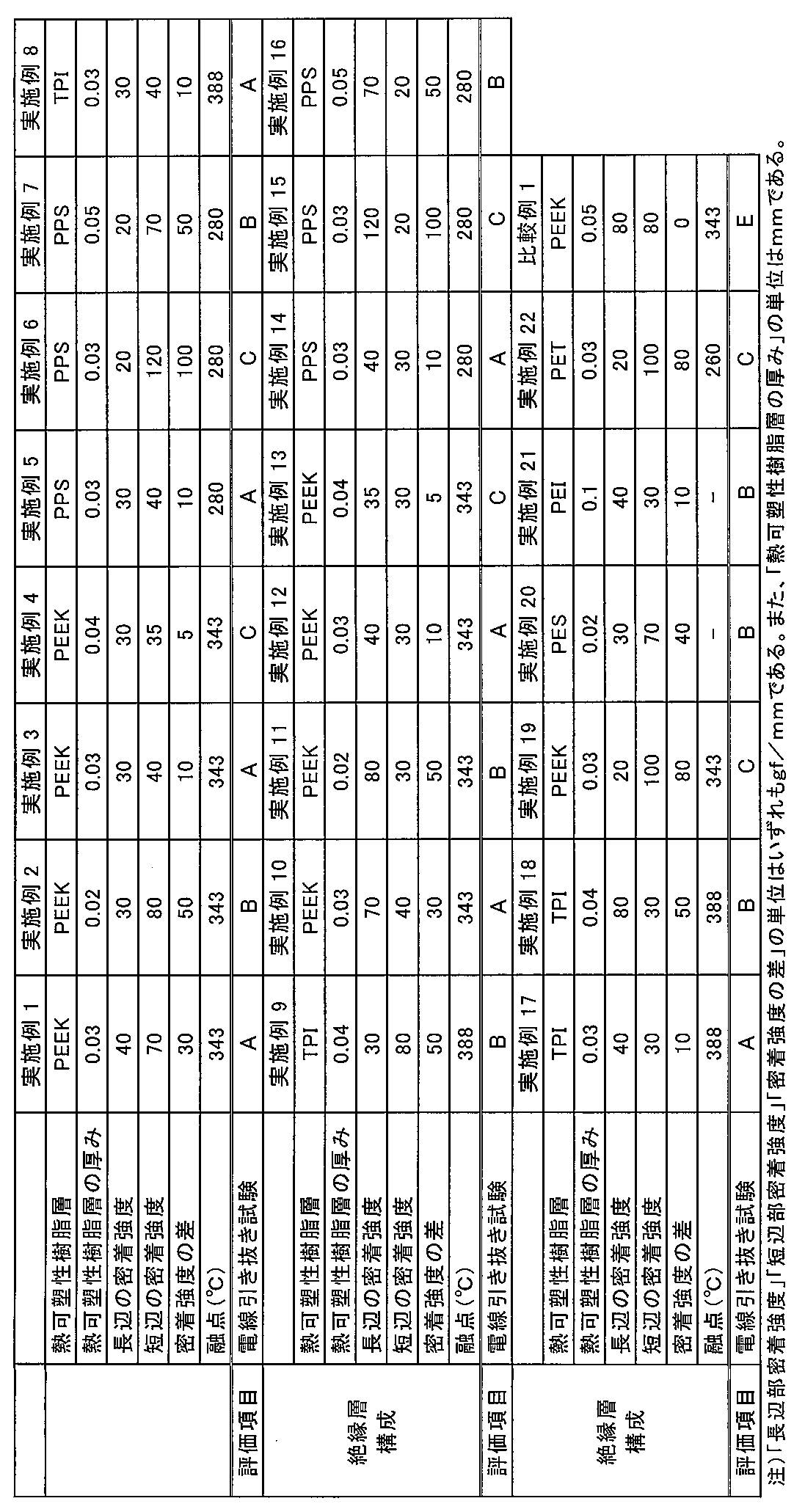
[表1注]
PEEK:ビクトレックスジャパン社製のPEEK381G(商品名)
PPS:ポリプラスチックス社製のジュラファイド0220A9(商品名)
TPI:三井化学社製のオーラムPL450C(商品名)
PES:住友化学株式会社製のスミカエクセル3600G(商品名)
PEI:サビックイノベーティブプラスチックス社製のウルテム1000(商品名)
PET:帝人化成社製のTR-8550T1(商品名)
PEEK:ビクトレックスジャパン社製のPEEK381G(商品名)
PPS:ポリプラスチックス社製のジュラファイド0220A9(商品名)
TPI:三井化学社製のオーラムPL450C(商品名)
PES:住友化学株式会社製のスミカエクセル3600G(商品名)
PEI:サビックイノベーティブプラスチックス社製のウルテム1000(商品名)
PET:帝人化成社製のTR-8550T1(商品名)
平角導体の1対の対向する辺に対する熱可塑性樹脂層と平角導体との密着強度と、平角導体の他の1対の対向する辺に対する熱可塑性樹脂層と平角導体との密着強度とが異なる実施例1~22の絶縁電線は、電線引き抜き試験において全て合格レベルであった。これに対して、平角導体の1対の対向する辺に対する熱可塑性樹脂層と平角導体との密着強度と、平角導体の他の1対の対向する辺に対する熱可塑性樹脂層と平角導体との密着強度とが異らない比較例1は電線引き抜き試験において不合格であった。
さらに、実施例1~22の中でも、実施例1~3、5、7~12、14、16~18、20および21が、より高水準で機械的特性(電線引き抜き試験結果)を満たすことがわかる。
さらに、実施例1~22の中でも、実施例1~3、5、7~12、14、16~18、20および21が、より高水準で機械的特性(電線引き抜き試験結果)を満たすことがわかる。
さらに、実施例1~22の絶縁電線について、下記2項目の試験を行った。
-キシレン浸漬後折り曲げ試験(耐溶剤性の評価)-
キシレン浸漬後の折り曲げ試験を次のように評価した。1%伸張した直線状の各絶縁電線をキシレン溶液に10秒浸漬させた。浸漬後取出し、絶縁電線を半径が2mmの鉄芯を軸に180°折り曲げ試験を行った。絶縁被覆層に剥離もしくは亀裂のいずれも確認できなかった場合を合格とし、剥離もしくは亀裂のいずれかが発生し目視で確認できた場合を不合格とした。
キシレン浸漬後の折り曲げ試験を次のように評価した。1%伸張した直線状の各絶縁電線をキシレン溶液に10秒浸漬させた。浸漬後取出し、絶縁電線を半径が2mmの鉄芯を軸に180°折り曲げ試験を行った。絶縁被覆層に剥離もしくは亀裂のいずれも確認できなかった場合を合格とし、剥離もしくは亀裂のいずれかが発生し目視で確認できた場合を不合格とした。
-耐熱老化特性の評価-
JIS C 3216-6 「巻線試験方法-第1部:全般事項」の「3.耐熱衝撃(エナメル線及びテープ巻線に適用)」を参照して、1%伸張した直状の各絶縁電線を200℃の恒温槽内に500時間静置した後に、絶縁層に亀裂が発生しているか否かを目視にて確認した。亀裂が確認できなかった場合を合格とし、亀裂が確認できた場合を不合格とした。
JIS C 3216-6 「巻線試験方法-第1部:全般事項」の「3.耐熱衝撃(エナメル線及びテープ巻線に適用)」を参照して、1%伸張した直状の各絶縁電線を200℃の恒温槽内に500時間静置した後に、絶縁層に亀裂が発生しているか否かを目視にて確認した。亀裂が確認できなかった場合を合格とし、亀裂が確認できた場合を不合格とした。
以上の試験結果において、実施例1~19の絶縁電線は、前記のように電線引き抜き試験が合格レベルであって、かつ、耐溶剤性および耐熱老化特性にも優れた。また、実施例20~22の絶縁電線は、この耐溶剤性または耐熱老化特性のいずれかの結果が劣ったが、電線引き抜き試験の結果は合格レベルであった。
上記の結果から、本発明の絶縁電線は、コイル、特にモーターコイルなどの電気・電子機器に好ましく適用できることがわかる。
本発明をその実施態様とともに説明したが、我々は特に指定しない限り我々の発明を説明のどの細部においても限定しようとするものではなく、添付の請求の範囲に示した発明の精神と範囲に反することなく幅広く解釈されるべきであると考える。
本願は、2014年12月26日に日本国で特許出願された特願2014-265390に基づく優先権を主張するものであり、これはここに参照してその内容を本明細書の記載の一部として取り込む。
1 導体
2 熱可塑性樹脂層
2a、22a 熱可塑性樹脂層の平角導体上部に接する部分(上部)
2b、22b 熱可塑性樹脂層の平角導体右側面部に接する部分(右側面部)
2c、22c 熱可塑性樹脂層の平角導体下部に接する部分(下部)
2d、22d 熱可塑性樹脂層の平角導体左側面部に接する部分(左側面部)
3a~3d ジグの各側面
4 電線試料
2 熱可塑性樹脂層
2a、22a 熱可塑性樹脂層の平角導体上部に接する部分(上部)
2b、22b 熱可塑性樹脂層の平角導体右側面部に接する部分(右側面部)
2c、22c 熱可塑性樹脂層の平角導体下部に接する部分(下部)
2d、22d 熱可塑性樹脂層の平角導体左側面部に接する部分(左側面部)
3a~3d ジグの各側面
4 電線試料
Claims (6)
- 平角導体上に熱可塑性樹脂層を有し、該平角導体の1対の対向する辺に対する該熱可塑性樹脂層と該平角導体との密着強度と、該平角導体の他の1対の対向する辺に対する該熱可塑性樹脂層の該平角導体との密着強度とが互いに異なる絶縁電線。
- 前記平角導体の1対の対向する辺に対する前記熱可塑性樹脂層と前記平角導体との密着強度と、前記平角導体の他の1対の対向する辺に対する前記熱可塑性樹脂層と前記平角導体との密着強度との差が5gf/mm~100gf/mmであることを特徴とする請求項1に記載の絶縁電線。
- 前記密着強度の差が10gf/mm~50gf/mmであることを特徴とする請求項1または2に記載の絶縁電線。
- 前記熱可塑性樹脂層を構成する熱可塑性樹脂が、ポリエーテルエーテルケトン、ポリエーテルケトンケトン、ポリケトン、ポリフェニレンサルファイドおよび熱可塑性ポリイミドからなる群から選択される少なくとも1種であることを特徴とする請求項1~3のいずれか1項に記載の絶縁電線。
- 前記平角導体が、銅、無酸素銅および銅合金からなることを特徴とする請求項1~4のいずれか1項に記載の絶縁電線。
- 請求項1~5のいずれか1項に記載の絶縁電線が、巻線加工されたことを特徴とするコイル。
Priority Applications (4)
| Application Number | Priority Date | Filing Date | Title |
|---|---|---|---|
| CN201580068126.5A CN107112083B (zh) | 2014-12-26 | 2015-09-14 | 绝缘电线和线圈 |
| EP15872372.6A EP3239989B1 (en) | 2014-12-26 | 2015-09-14 | Insulated electric wire and coil |
| KR1020177018928A KR102278188B1 (ko) | 2014-12-26 | 2015-09-14 | 절연전선 및 코일 |
| US15/632,044 US10210966B2 (en) | 2014-12-26 | 2017-06-23 | Insulated wire and coil |
Applications Claiming Priority (2)
| Application Number | Priority Date | Filing Date | Title |
|---|---|---|---|
| JP2014265390A JP5778331B1 (ja) | 2014-12-26 | 2014-12-26 | 絶縁電線およびコイル |
| JP2014-265390 | 2014-12-26 |
Related Child Applications (1)
| Application Number | Title | Priority Date | Filing Date |
|---|---|---|---|
| US15/632,044 Continuation US10210966B2 (en) | 2014-12-26 | 2017-06-23 | Insulated wire and coil |
Publications (1)
| Publication Number | Publication Date |
|---|---|
| WO2016103803A1 true WO2016103803A1 (ja) | 2016-06-30 |
Family
ID=54192738
Family Applications (1)
| Application Number | Title | Priority Date | Filing Date |
|---|---|---|---|
| PCT/JP2015/075972 Ceased WO2016103803A1 (ja) | 2014-12-26 | 2015-09-14 | 絶縁電線およびコイル |
Country Status (7)
| Country | Link |
|---|---|
| US (1) | US10210966B2 (ja) |
| EP (1) | EP3239989B1 (ja) |
| JP (1) | JP5778331B1 (ja) |
| KR (1) | KR102278188B1 (ja) |
| CN (1) | CN107112083B (ja) |
| MY (1) | MY167709A (ja) |
| WO (1) | WO2016103803A1 (ja) |
Families Citing this family (7)
| Publication number | Priority date | Publication date | Assignee | Title |
|---|---|---|---|---|
| JP7031377B2 (ja) | 2018-03-05 | 2022-03-08 | 三菱マテリアル株式会社 | コイル |
| WO2019227116A1 (de) * | 2018-05-29 | 2019-12-05 | Miba Aktiengesellschaft | Elektrischer leiter zur verwendung in elektrischen maschinen |
| AT521301B1 (de) * | 2018-05-29 | 2020-04-15 | Miba Ag | Stator mit Isolationsschicht |
| JP2020045996A (ja) * | 2018-09-20 | 2020-03-26 | 日本電産サンキョー株式会社 | ダンパー機構、およびアクチュエータ |
| JP7130591B2 (ja) * | 2019-04-23 | 2022-09-05 | 矢崎総業株式会社 | バスバー電線 |
| EP3987551B1 (en) * | 2019-08-23 | 2026-04-15 | Zeus Company LLC | Polymer-coated wires |
| TWI888721B (zh) * | 2022-04-19 | 2025-07-01 | 奇美實業股份有限公司 | 絕緣電線及其製造方法、線圈以及電子機器 |
Citations (1)
| Publication number | Priority date | Publication date | Assignee | Title |
|---|---|---|---|---|
| JP2014103045A (ja) * | 2012-11-21 | 2014-06-05 | Hitachi Metals Ltd | 絶縁電線及びその製造方法 |
Family Cites Families (22)
| Publication number | Priority date | Publication date | Assignee | Title |
|---|---|---|---|---|
| JP3313277B2 (ja) * | 1995-09-22 | 2002-08-12 | 古河サーキットフォイル株式会社 | ファインパターン用電解銅箔とその製造方法 |
| MY120077A (en) * | 1998-06-26 | 2005-08-30 | Ibiden Co Ltd | Multilayer printed wiring board having a roughened inner conductor layer and production method thereof |
| US20070128827A1 (en) * | 2001-09-12 | 2007-06-07 | Faris Sadeg M | Method and system for increasing yield of vertically integrated devices |
| US7420147B2 (en) * | 2001-09-12 | 2008-09-02 | Reveo, Inc. | Microchannel plate and method of manufacturing microchannel plate |
| US7033910B2 (en) * | 2001-09-12 | 2006-04-25 | Reveo, Inc. | Method of fabricating multi layer MEMS and microfluidic devices |
| EP1679727A4 (en) * | 2003-10-23 | 2015-02-25 | Toshiba Kk | INDUCTIVE DEVICE AND METHOD FOR THE PRODUCTION THEREOF |
| DE102005028704B4 (de) * | 2005-06-20 | 2016-09-08 | Infineon Technologies Ag | Verfahren zur Herstellung eines Halbleiterbauteils mit in Kunststoffgehäusemasse eingebetteten Halbleiterbauteilkomponenten |
| JP4445448B2 (ja) * | 2005-09-16 | 2010-04-07 | 株式会社東芝 | 回路基板の製造方法 |
| US20090146280A1 (en) * | 2005-11-28 | 2009-06-11 | Dai Nippon Printing Co., Ltd. | Circuit member, manufacturing method of the circuit member, and semiconductor device including the circuit member |
| CN101558459B (zh) * | 2007-03-30 | 2012-06-13 | 古河电气工业株式会社 | 绝缘电线的制造方法及其制造装置 |
| WO2010024233A1 (ja) * | 2008-08-27 | 2010-03-04 | 日本電気株式会社 | 機能素子を内蔵可能な配線基板及びその製造方法 |
| US20140216340A1 (en) * | 2010-04-08 | 2014-08-07 | Furukawa Electric Co., Ltd. | Method and apparatus for producing insulated wire |
| JP5624942B2 (ja) * | 2011-05-27 | 2014-11-12 | 日立オートモティブシステムズ株式会社 | 回転電機およびその製造方法 |
| JP2013020726A (ja) * | 2011-07-07 | 2013-01-31 | Nitto Denko Corp | 平角電線用被覆材、被覆平角電線及び電気機器 |
| JP5454804B2 (ja) * | 2011-08-12 | 2014-03-26 | 古河電気工業株式会社 | 絶縁ワイヤ |
| KR101479658B1 (ko) * | 2011-11-18 | 2015-01-06 | 제일모직 주식회사 | 가압착 공정성이 개선된 이방성 도전 필름 |
| JP2013191356A (ja) * | 2012-03-13 | 2013-09-26 | Hitachi Cable Ltd | 絶縁電線及びそれを用いて形成されたコイル |
| JP5486646B2 (ja) * | 2012-07-20 | 2014-05-07 | 株式会社デンソー | 絶縁電線 |
| JP2014238927A (ja) * | 2013-06-06 | 2014-12-18 | 日立金属株式会社 | 絶縁電線 |
| JP6382224B2 (ja) * | 2013-12-26 | 2018-08-29 | 古河電気工業株式会社 | 絶縁ワイヤ、コイルおよび電気・電子機器ならびに皮膜剥離防止絶縁ワイヤの製造方法 |
| US9324476B2 (en) * | 2014-02-05 | 2016-04-26 | Essex Group, Inc. | Insulated winding wire |
| JP6156250B2 (ja) * | 2014-05-08 | 2017-07-05 | 株式会社デンソー | 回転電機の固定子及びその固定子を備えた回転電機 |
-
2014
- 2014-12-26 JP JP2014265390A patent/JP5778331B1/ja active Active
-
2015
- 2015-09-14 KR KR1020177018928A patent/KR102278188B1/ko active Active
- 2015-09-14 EP EP15872372.6A patent/EP3239989B1/en active Active
- 2015-09-14 WO PCT/JP2015/075972 patent/WO2016103803A1/ja not_active Ceased
- 2015-09-14 MY MYPI2017702358A patent/MY167709A/en unknown
- 2015-09-14 CN CN201580068126.5A patent/CN107112083B/zh active Active
-
2017
- 2017-06-23 US US15/632,044 patent/US10210966B2/en active Active
Patent Citations (1)
| Publication number | Priority date | Publication date | Assignee | Title |
|---|---|---|---|---|
| JP2014103045A (ja) * | 2012-11-21 | 2014-06-05 | Hitachi Metals Ltd | 絶縁電線及びその製造方法 |
Also Published As
| Publication number | Publication date |
|---|---|
| KR20170099932A (ko) | 2017-09-01 |
| JP2016126866A (ja) | 2016-07-11 |
| EP3239989B1 (en) | 2020-07-22 |
| CN107112083A (zh) | 2017-08-29 |
| CN107112083B (zh) | 2019-09-27 |
| US10210966B2 (en) | 2019-02-19 |
| EP3239989A1 (en) | 2017-11-01 |
| KR102278188B1 (ko) | 2021-07-19 |
| EP3239989A4 (en) | 2018-08-22 |
| MY167709A (en) | 2018-09-21 |
| JP5778331B1 (ja) | 2015-09-16 |
| US20170358382A1 (en) | 2017-12-14 |
Similar Documents
| Publication | Publication Date | Title |
|---|---|---|
| JP5778331B1 (ja) | 絶縁電線およびコイル | |
| CN107004466B (zh) | 绝缘电线、线圈和电气/电子设备以及绝缘电线的制造方法 | |
| CN104170024B (zh) | 抗变频器浪涌绝缘电线 | |
| KR102000380B1 (ko) | 내굽힘 가공성이 우수한 절연전선, 그것을 이용한 코일 및 전자·전기 기기 | |
| US9691521B2 (en) | Rectangular insulated wire and electric generator coil | |
| JP6382224B2 (ja) | 絶縁ワイヤ、コイルおよび電気・電子機器ならびに皮膜剥離防止絶縁ワイヤの製造方法 | |
| EP3093855B1 (en) | Insulated electric wire, coil and electric/electronic device, and cracking prevention method for insulated electric wire | |
| JP6932642B2 (ja) | 絶縁電線、絶縁電線の製造方法、コイル、回転電機および電気・電子機器 | |
| CN114270454B (zh) | 具有热塑性绝缘部的磁导线 | |
| CN104185879A (zh) | 绝缘电线、电气设备及绝缘电线的制造方法 | |
| KR20170080632A (ko) | 절연 와이어 및 회전 전기 | |
| EP3089169B1 (en) | Insulated wire, coil, and electronic/electrical equipment | |
| WO2018051991A1 (ja) | 絶縁電線、コイルおよび電気・電子機器 | |
| KR102166630B1 (ko) | 절연 전선, 코일 및 전기·전자 기기 | |
| JP6490505B2 (ja) | 絶縁電線、コイル及び電気・電子機器 |
Legal Events
| Date | Code | Title | Description |
|---|---|---|---|
| 121 | Ep: the epo has been informed by wipo that ep was designated in this application |
Ref document number: 15872372 Country of ref document: EP Kind code of ref document: A1 |
|
| NENP | Non-entry into the national phase |
Ref country code: DE |
|
| REEP | Request for entry into the european phase |
Ref document number: 2015872372 Country of ref document: EP |
|
| ENP | Entry into the national phase |
Ref document number: 20177018928 Country of ref document: KR Kind code of ref document: A |