WO2016103858A1 - 積層鉄心用材料および積層鉄心の製造方法 - Google Patents
積層鉄心用材料および積層鉄心の製造方法 Download PDFInfo
- Publication number
- WO2016103858A1 WO2016103858A1 PCT/JP2015/078954 JP2015078954W WO2016103858A1 WO 2016103858 A1 WO2016103858 A1 WO 2016103858A1 JP 2015078954 W JP2015078954 W JP 2015078954W WO 2016103858 A1 WO2016103858 A1 WO 2016103858A1
- Authority
- WO
- WIPO (PCT)
- Prior art keywords
- steel
- laminated core
- plate
- steel plates
- laminated
- Prior art date
- Legal status (The legal status is an assumption and is not a legal conclusion. Google has not performed a legal analysis and makes no representation as to the accuracy of the status listed.)
- Ceased
Links
Images


Classifications
-
- C—CHEMISTRY; METALLURGY
- C21—METALLURGY OF IRON
- C21D—MODIFYING THE PHYSICAL STRUCTURE OF FERROUS METALS; GENERAL DEVICES FOR HEAT TREATMENT OF FERROUS OR NON-FERROUS METALS OR ALLOYS; MAKING METAL MALLEABLE, e.g. BY DECARBURISATION OR TEMPERING
- C21D8/00—Modifying the physical properties of ferrous metals or ferrous alloys by deformation combined with, or followed by, heat treatment
- C21D8/12—Modifying the physical properties of ferrous metals or ferrous alloys by deformation combined with, or followed by, heat treatment during manufacturing of articles with special electromagnetic properties
- C21D8/1216—Modifying the physical properties of ferrous metals or ferrous alloys by deformation combined with, or followed by, heat treatment during manufacturing of articles with special electromagnetic properties characterised by the working steps
- C21D8/1233—Cold rolling
-
- H—ELECTRICITY
- H01—ELECTRIC ELEMENTS
- H01F—MAGNETS; INDUCTANCES; TRANSFORMERS; SELECTION OF MATERIALS FOR THEIR MAGNETIC PROPERTIES
- H01F3/00—Cores, Yokes, or armatures
- H01F3/02—Cores, Yokes, or armatures made from sheets
-
- B—PERFORMING OPERATIONS; TRANSPORTING
- B32—LAYERED PRODUCTS
- B32B—LAYERED PRODUCTS, i.e. PRODUCTS BUILT-UP OF STRATA OF FLAT OR NON-FLAT, e.g. CELLULAR OR HONEYCOMB, FORM
- B32B15/00—Layered products comprising a layer of metal
- B32B15/01—Layered products comprising a layer of metal all layers being exclusively metallic
- B32B15/011—Layered products comprising a layer of metal all layers being exclusively metallic all layers being formed of iron alloys or steels
-
- C—CHEMISTRY; METALLURGY
- C21—METALLURGY OF IRON
- C21D—MODIFYING THE PHYSICAL STRUCTURE OF FERROUS METALS; GENERAL DEVICES FOR HEAT TREATMENT OF FERROUS OR NON-FERROUS METALS OR ALLOYS; MAKING METAL MALLEABLE, e.g. BY DECARBURISATION OR TEMPERING
- C21D8/00—Modifying the physical properties of ferrous metals or ferrous alloys by deformation combined with, or followed by, heat treatment
- C21D8/02—Modifying the physical properties of ferrous metals or ferrous alloys by deformation combined with, or followed by, heat treatment during manufacturing of plates or strips
- C21D8/0221—Modifying the physical properties of ferrous metals or ferrous alloys by deformation combined with, or followed by, heat treatment during manufacturing of plates or strips characterised by the working steps
- C21D8/0236—Cold rolling
-
- C—CHEMISTRY; METALLURGY
- C21—METALLURGY OF IRON
- C21D—MODIFYING THE PHYSICAL STRUCTURE OF FERROUS METALS; GENERAL DEVICES FOR HEAT TREATMENT OF FERROUS OR NON-FERROUS METALS OR ALLOYS; MAKING METAL MALLEABLE, e.g. BY DECARBURISATION OR TEMPERING
- C21D8/00—Modifying the physical properties of ferrous metals or ferrous alloys by deformation combined with, or followed by, heat treatment
- C21D8/12—Modifying the physical properties of ferrous metals or ferrous alloys by deformation combined with, or followed by, heat treatment during manufacturing of articles with special electromagnetic properties
-
- C—CHEMISTRY; METALLURGY
- C21—METALLURGY OF IRON
- C21D—MODIFYING THE PHYSICAL STRUCTURE OF FERROUS METALS; GENERAL DEVICES FOR HEAT TREATMENT OF FERROUS OR NON-FERROUS METALS OR ALLOYS; MAKING METAL MALLEABLE, e.g. BY DECARBURISATION OR TEMPERING
- C21D9/00—Heat treatment, e.g. annealing, hardening, quenching or tempering, adapted for particular articles; Furnaces therefor
- C21D9/46—Heat treatment, e.g. annealing, hardening, quenching or tempering, adapted for particular articles; Furnaces therefor for sheet metals
-
- C—CHEMISTRY; METALLURGY
- C22—METALLURGY; FERROUS OR NON-FERROUS ALLOYS; TREATMENT OF ALLOYS OR NON-FERROUS METALS
- C22C—ALLOYS
- C22C38/00—Ferrous alloys, e.g. steel alloys
- C22C38/06—Ferrous alloys, e.g. steel alloys containing aluminium
-
- H—ELECTRICITY
- H01—ELECTRIC ELEMENTS
- H01F—MAGNETS; INDUCTANCES; TRANSFORMERS; SELECTION OF MATERIALS FOR THEIR MAGNETIC PROPERTIES
- H01F1/00—Magnets or magnetic bodies characterised by the magnetic materials therefor; Selection of materials for their magnetic properties
- H01F1/01—Magnets or magnetic bodies characterised by the magnetic materials therefor; Selection of materials for their magnetic properties of inorganic materials
- H01F1/012—Magnets or magnetic bodies characterised by the magnetic materials therefor; Selection of materials for their magnetic properties of inorganic materials adapted for magnetic entropy change by magnetocaloric effect, e.g. used as magnetic refrigerating material
- H01F1/015—Metals or alloys
-
- H—ELECTRICITY
- H01—ELECTRIC ELEMENTS
- H01F—MAGNETS; INDUCTANCES; TRANSFORMERS; SELECTION OF MATERIALS FOR THEIR MAGNETIC PROPERTIES
- H01F27/00—Details of transformers or inductances, in general
- H01F27/24—Magnetic cores
- H01F27/245—Magnetic cores made from sheets, e.g. grain-oriented
-
- H—ELECTRICITY
- H01—ELECTRIC ELEMENTS
- H01F—MAGNETS; INDUCTANCES; TRANSFORMERS; SELECTION OF MATERIALS FOR THEIR MAGNETIC PROPERTIES
- H01F41/00—Apparatus or processes specially adapted for manufacturing or assembling magnets, inductances or transformers; Apparatus or processes specially adapted for manufacturing materials characterised by their magnetic properties
- H01F41/02—Apparatus or processes specially adapted for manufacturing or assembling magnets, inductances or transformers; Apparatus or processes specially adapted for manufacturing materials characterised by their magnetic properties for manufacturing cores, coils, or magnets
- H01F41/0206—Manufacturing of magnetic cores by mechanical means
- H01F41/0233—Manufacturing of magnetic circuits made from sheets
-
- H—ELECTRICITY
- H02—GENERATION; CONVERSION OR DISTRIBUTION OF ELECTRIC POWER
- H02K—DYNAMO-ELECTRIC MACHINES
- H02K15/00—Processes or apparatus specially adapted for manufacturing, assembling, maintaining or repairing of dynamo-electric machines
- H02K15/02—Processes or apparatus specially adapted for manufacturing, assembling, maintaining or repairing of dynamo-electric machines of stator or rotor bodies
Definitions
- the present invention relates to a laminated core material used for producing a laminated core and a method for producing the laminated core.
- a high permeability steel plate such as an electromagnetic steel plate has been used as a material used when manufacturing a laminated iron core, that is, a laminated iron core material.
- a thin steel plate having a high magnetic permeability for example, an electromagnetic steel plate having a reduced thickness
- punched bodies a plurality of iron core-shaped steel plate structures (hereinafter referred to as punched bodies) punched by a press machine are stacked and integrated in the thickness direction.
- punched bodies iron core-shaped steel plate structures
- the electrical steel sheet which is a laminated core material, is required to have a thin plate thickness for the purpose of reducing eddy current loss of the laminated core that occurs during high-speed rotation of an electric motor or the like.
- electrical steel sheets having a plate thickness of 0.35 [mm] or less.
- Patent Document 1 As a prior art for solving these problems, for example, in Patent Document 1, before a step of punching out an electromagnetic steel sheet with a press machine, portions of the plurality of electromagnetic steel sheets that are not used for the motor core are fixed to each other. And the manufacturing method of the electric motor core which performs the process which closely_contact
- Patent Document 3 discloses a method of applying an inorganic adhesive mainly composed of alumina or silica to a plurality of electromagnetic steel sheets and bonding the plurality of electromagnetic steel sheets.
- Patent Document 4 discloses a method of bonding a plurality of electrical steel sheets with an adhesive layer made of an organic resin having a glass transition temperature or a softening temperature of 50 [° C.] or higher.
- Patent Document 5 a plurality of electromagnetic steel sheets are laminated together by an adhesive film interposed between a plurality of electromagnetic steel sheets to form a multilayer laminated steel sheet, and this multilayer laminated steel sheet is punched out by a press machine and laminated.
- a method of manufacturing an iron core is disclosed.
- Patent Document 6 discloses a method in which a plurality of electromagnetic steel sheets are bonded with a shear bond strength of 50 [Kgf / cm 2 ] or more, and then the plurality of electromagnetic steel sheets are subjected to punching.
- JP 2003-153503 A Japanese Patent Laid-Open No. 2003-264962 JP 2005-332976 A Japanese Patent No. 4581228 JP 2005-191033 A JP 2000-173815 A
- the present invention has been made in view of the above circumstances, and provides a laminated core material and a laminated core manufacturing method capable of ensuring a good punching shape and realizing a laminated core with a high space factor.
- the purpose is to do.
- the laminated core material according to the present invention is a laminated core material used as a steel sheet that is punched in a plurality of layers when producing a laminated core.
- the surface roughness of the steel sheet constituting the laminated core material is 0.40 [ ⁇ m] or less in terms of arithmetic average roughness Ra, and is used as at least the laminated iron core of the steel sheets constituting the laminated core material.
- the thickness deviation in the plate width direction of the portion to be formed is 3 [ ⁇ m] or less per 500 [mm].
- the laminated core material according to the present invention is characterized in that, in the above invention, the sum of the surface roughness and a value obtained by multiplying the plate thickness deviation by 0.05 is less than 0.5. To do.
- the laminated core material according to the present invention is characterized in that, in the above invention, the thickness of the steel sheet constituting the laminated core material is 0.25 [mm] or less.
- the manufacturing method of the laminated core according to the present invention includes an overlapping step of overlapping a plurality of steel plates, and a punching step of simultaneously punching the overlapped plurality of steel plates to obtain a punched body of the plurality of steel plates,
- a laminated integration step of laminating and integrating the punched bodies to form a laminated iron core, and the surface roughness of the steel sheets to be overlaid in the overlapping step is an arithmetic average roughness Ra of 0.40 [ ⁇ m].
- the thickness deviation in the plate width direction of at least a portion used as the laminated core of the steel plates is 3 [ ⁇ m] or less per 500 [mm].
- the sum of the value obtained by multiplying the plate thickness deviation by 0.05 and the surface roughness is less than 0.5.
- the method for manufacturing a laminated core according to the present invention is characterized in that, in the above invention, a thickness of the steel plates to be overlapped in the overlapping step is 0.25 [mm] or less.
- the plurality of stacked steel plates are pressed in the plate thickness direction, and air existing between the overlapping surfaces of the plurality of steel plates is removed.
- the punching step further includes a punching step, wherein the punching step punches the plurality of steel plates after the air is removed from between the overlapping surfaces at the same time.
- the method for manufacturing a laminated core according to the present invention further includes an application step of applying an oily agent to the plurality of stacked steel sheets in the above invention, wherein the pressing step applies the oily agent.
- the plurality of later steel plates are pressed in the plate thickness direction.
- the manufacturing method of the laminated core concerning this invention WHEREIN: Cold rolling and surface treatment are performed with respect to the said steel plate before superposition
- the said surface roughness is arithmetic average roughness Ra.
- the method further includes a cold rolling surface treatment step of adjusting the thickness deviation to 40 [ ⁇ m] or less and adjusting the plate thickness deviation to 3 [ ⁇ m] or less per 500 [mm], and the superposing step is adjusted by the cold rolling surface treatment step.
- a plurality of the steel plates having the surface roughness and the thickness deviation are overlapped.
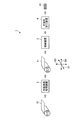
- FIG. 1 is a diagram showing a configuration example of a laminated core manufacturing apparatus according to an embodiment of the present invention.
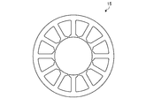
- FIG. 2 is a view showing an example of a laminated core manufactured using the laminated core material according to the embodiment of the present invention.
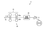
- FIG. 3 is a diagram illustrating an example of a main configuration of the cold-rolled surface treatment apparatus in the embodiment of the present invention.
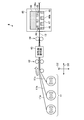
- FIG. 4 is a diagram illustrating an example of a main configuration of the punching apparatus according to the embodiment of the present invention.
- FIG. 5 is a flowchart showing an example of a method for manufacturing a laminated core according to an embodiment of the present invention.
- FIG. 1 is a diagram showing a configuration example of a laminated core manufacturing apparatus according to an embodiment of the present invention.
- FIG. 2 is a view showing an example of a laminated core manufactured using the laminated core material according to the embodiment of the present invention.
- FIG. 3 is a diagram illustrating an example of a main configuration of the cold-rolled surface treatment apparatus
- FIG. 6 is a diagram showing the influence of the surface roughness of the electrical steel sheet as the laminated iron core material on the roundness as the iron core shape after punching.
- FIG. 7 is a diagram showing the influence of the thickness deviation of the electromagnetic steel sheet as the laminated iron core material on the roundness as the iron core shape after punching.
- FIG. 8 is a diagram showing the influence of the manufacturing process of the electromagnetic steel sheet as the laminated core material and the roundness as the core shape after punching by the simultaneous punching number.
- FIG. 9 is a diagram showing the influence of the rolling oil application area ratio of the magnetic steel sheet as the laminated iron core material on the roundness as the iron core shape after punching.
- FIG. 1 is a diagram showing a configuration example of a laminated core manufacturing apparatus according to an embodiment of the present invention.
- the laminated core manufacturing apparatus 1 manufactures the laminated core 15 using the steel plate 11 as a laminated core material, and makes a part of a laminated core manufacturing line.
- Such a laminated core manufacturing apparatus 1 includes a cold-rolled surface treatment apparatus 2, an annealing apparatus 3, and a punching apparatus 4, as shown in FIG.
- thick line arrows indicate the flow of conveyance of the steel plates 10 and 11 or the laminated core 15.
- the cold-rolled surface treatment apparatus 2 forms a laminated core material by cold rolling and surface treatment. As shown in FIG. 1, the cold-rolled surface treatment apparatus 2 sequentially receives the steel plates 10 in a coiled state, performs cold rolling and surface treatment on the received steel plates 10, The plate thickness, the surface roughness, and the plate thickness deviation in the plate width direction D1 are adjusted. At this time, the cold-rolled surface treatment apparatus 2 reduces, for example, the thickness of the steel plate 10 to 0.25 [mm] or less, and the surface roughness of the steel plate 10 is 0.40 [ ⁇ m] or less in terms of arithmetic average roughness Ra. The thickness deviation in the plate width direction D1 of the steel plate 10 is reduced to 3 [ ⁇ m] or less per 500 [mm].
- the cold-rolling surface treatment apparatus 2 processes the steel plate 10 as a raw material into the steel plate 11 as a laminated core material. Then, the cold rolling surface treatment apparatus 2 winds up the steel plate 11 obtained as a laminated core material into a coil shape. As shown in FIG. 1, the steel plate 11 is sequentially conveyed from the cold-rolled surface treatment device 2 to the annealing device 3 in a coiled state.
- the steel plate 10 is a material used to manufacture a steel plate 11 as a laminated core material.
- Such a steel plate 10 is manufactured by hot-rolling a slab having a predetermined metal composition after heating and performing necessary treatments such as annealing and pickling on the obtained hot-rolled steel plate. .
- the annealing apparatus 3 performs a finish annealing process on the material for the laminated core manufactured by the cold rolling surface treatment apparatus 2, that is, the steel plate 11.
- the annealing device 3 is installed at the subsequent stage of the cold rolling surface treatment device 2 described above.
- the annealing device 3 continuously finish-anneals the steel plate 11 from the cold-rolled surface treatment device 2, and winds up the steel plate 11 after the finish annealing into a coil shape.
- the steel plate 11 after finish annealing is sequentially conveyed from the annealing device 3 to the punching device 4 in a state of being wound in a coil shape.
- the steel plate 11 after finish annealing is an electromagnetic steel plate (non-oriented electrical steel plate or the like) having a high magnetic permeability.
- the punching device 4 is for forming a laminated core using the laminated core material according to the embodiment of the present invention. As shown in FIG. 1, the punching device 4 is installed at the subsequent stage of the annealing device 3. The punching device 4 receives a plurality of steel plates 11 after finish annealing by the annealing device 3 as a laminated core material, and superimposes the received steel plates 11 in the plate thickness direction D2. Thereafter, the punching device 4 simultaneously punches the superposed steel plates 11 into a target iron core shape. Thereby, the punching apparatus 4 obtains a plurality of punched bodies (not shown) that overlap with each other in a target iron core shape from the plurality of steel plates 11. The punching apparatus 4 stacks and integrates a plurality of iron core-shaped punched bodies thus obtained in the plate thickness direction D2. In this way, the punching device 4 forms (manufactures) the target laminated core 15.
- FIG. 2 is a diagram showing an example of a laminated core manufactured using the laminated core material according to the embodiment of the present invention.
- the lamination direction of the laminated core 15 shown in FIG. 2 is a direction perpendicular to the paper surface of FIG. 2, and is the same as the thickness direction of the punched body of the steel plate 11 constituting the laminated core 15.
- the punching apparatus 4 has a plurality of overlapping steel plates 11 in an iron core shape (ring shape) corresponding to the laminated iron core 15 in order to produce a ring shaped laminated iron core 15 as shown in FIG. At the same time. Thereby, the punching apparatus 4 obtains a plurality of punched bodies having the same ring shape as the laminated core 15 shown in FIG.
- the punching apparatus 4 can manufacture a ring-shaped laminated core 15 as shown in FIG. 2 by laminating a plurality of these punched bodies in the plate thickness direction D2 and integrating them.
- the plate width direction D1 is the plate width direction of the steel plate 11 as the laminated core material.
- the plate thickness direction D2 is the plate thickness direction of the steel plate 11.
- the longitudinal direction D3 is the longitudinal direction (rolling direction) of the steel plate 11.
- the plate width direction D1, the plate thickness direction D2, and the longitudinal direction D3 are perpendicular to each other as shown in FIG.
- the plate width direction D1, the plate thickness direction D2, and the longitudinal direction D3 are the same for the steel plate 10 as a material.
- the laminated core material according to the embodiment of the present invention is a high-permeability material such as an electromagnetic steel plate used as a steel plate that is punched in a plurality of layers when producing a laminated core.
- the steel plate 11 as the laminated core material is obtained by performing cold rolling and surface treatment on the plate thickness, surface roughness, and plate thickness deviation of the plate width direction D1 as described above. It is manufactured by adjusting by.
- the steel plate 11 has the same composition as that of the steel plate 10 before cold rolling (for example, a composition as an electromagnetic steel plate), and is a thin steel plate in which the surface roughness and the plate thickness deviation in the plate width direction D1 are reduced compared to the steel plate 10. It is.
- the surface roughness of the steel sheet 11 constituting the laminated core material as described above is 0.40 [ ⁇ m] or less in terms of arithmetic average roughness Ra, and the thickness of the steel sheet 11 is 0.25 [mm] or less. is there.
- the plate thickness deviation in the plate width direction D1 of at least a portion used as the laminated core 15 (that is, a portion punched into the iron core shape) of the steel plates 11 constituting the laminated core material as described above is 500 [mm]. Per [ ⁇ m] or less.
- the surface roughness of the steel plate 11 affects the step of simultaneously punching a plurality of steel plates 11 by the punching device 4. Specifically, when the surface roughness of the steel plate 11 is excessively large, a gap is formed to allow air to easily enter between the overlapping surfaces of the plurality of steel plates 11 overlapped to be punched into the iron core shape. Due to the air entering the gap between the overlapping surfaces, the plurality of steel plates 11 are bent, and as a result, the punched bodies of the plurality of steel plates 11 are uneven in shape.
- the upper and lower sides in the plate thickness direction D2 A relative positional shift between the overlapping steel plates 11 occurs.
- the punched bodies of the plurality of steel plates 11 are laminated in a state of being deformed from the target iron core shape or having a stress.
- the surface roughness of the steel plate 11 is preferably set to 0.30 [ ⁇ m] or less.
- the thickness deviation in the plate width direction D1 of the steel plate 11 is 3 [ ⁇ m] or less per 500 [mm].
- the surface roughness of the steel plate 11 is 0.40 [ ⁇ m] or less in terms of arithmetic average roughness Ra, and the plate thickness deviation x in the plate width direction D1 of the steel plate 11 is 3 per 500 [mm]. [ ⁇ m] or less.
- the surface roughness Ra that is, the surface roughness at the arithmetic average roughness Ra
- the plate thickness deviation x of the steel plate 11 are expressed by the following formulas ( It is desirable to satisfy 1).
- the increase in eddy current loss generated in the laminated core 15 dominates the energy loss of the entire laminated core 15.
- Energy loss due to an increase in eddy current loss in the laminated core 15 can be suppressed by setting the plate thickness of the steel plate 11 constituting the laminated core material to 0.25 [mm] or less. This is because by reducing the plate thickness of the steel plate 11 to 0.25 [mm] or less, energy loss due to eddy current inside the punched body of the steel plate 11 constituting the laminated iron core 15 can be suppressed.
- it is desirable that the thickness of the steel plate 11 is 0.20 [mm] or less.
- FIG. 3 is a diagram illustrating an example of a main configuration of the cold-rolled surface treatment apparatus in the embodiment of the present invention.
- the cold-rolled surface treatment apparatus 2 in the embodiment of the present invention forms a laminated core material by cold rolling and surface treatment of a steel sheet 10 as a raw material, and as shown in FIG. 3, tandem cold rolling Machine 21 and a surface treatment unit 25.
- the tandem cold rolling mill 21 continuously cold-rolls the steel plates 10 that are sequentially passed through, and a plurality of the tandem cold rolling mills 21 that are arranged in parallel along the plate-passing direction of the steel plates 10 (see the bold arrows in FIG. 3). Consists of a rolling mill.
- Each of the plurality of rolling mills constituting the tandem cold rolling mill 21 includes a pair of rolling rolls that sandwich the steel plate 10 and sequentially cold-rolls the steel plate 10 by the action of the pair of rolling rolls.
- the tandem cold rolling mill 21 having such a configuration sequentially cold-rolls the steel plate 10 by a plurality of rolling mills while running the steel plate 10 from the entry side end toward the exit side end.
- the tandem cold rolling mill 21 sets the plate thickness of the steel plate 10 to 0.25 [mm] or less.
- the tandem cold rolling mill 21 sequentially sends the steel plates 10 thus cold-rolled to a thickness of 0.25 [mm] or less toward the surface treatment unit 25.
- the surface treatment unit 25 performs surface treatment for adjusting the surface roughness of the steel plate 10 after cold rolling and the plate thickness deviation in the plate width direction D1 (see FIG. 1). As shown in FIG. 3, the surface treatment unit 25 is disposed at the rear stage of the tandem cold rolling mill 21, that is, downstream of the tandem cold rolling mill 21 in the sheet passing direction of the steel plate 10. The surface treatment unit 25 adjusts the surface roughness of the steel sheet 10 to 0.40 [ ⁇ m] or less in terms of arithmetic average roughness Ra by performing a predetermined surface treatment on the steel sheet 10 after cold rolling. The plate thickness deviation in the plate width direction D1 of the steel plate 10 is adjusted to 3 [ ⁇ m] or less per 500 [mm].
- the steel sheet 10 as the material has an arithmetic average roughness Ra of 0.40 [ ⁇ m] or less and a thickness deviation in the sheet width direction D1 of 3 [ ⁇ m] or less per 500 [mm].
- the steel plate 11 formed by the actions of the tandem cold rolling mill 21 and the surface treatment unit 25 is wound from the surface treatment unit 25 and then wound into a coil shape, as shown in FIG.
- the surface treatment of the steel plate 10 by the surface treatment unit 25 may be performed by lightly rolling the steel plate 10 with a roll having a smooth surface, or by physically grinding the surface of the steel plate 10.
- the surface of the steel plate 10 may be chemically polished using an acidic liquid.
- the surface treatment unit 25 includes a required number of reduction rolls that have been polished in advance so that the roughness of the roll surface is 0.4 [ ⁇ m] or less in terms of arithmetic average roughness Ra.
- the surface roughness of the steel plate 10 and the plate thickness deviation in the plate width direction D1 may be adjusted to values in the above-described range by lightly reducing the surface of the plate.
- the surface treatment unit 25 includes grinding means such as a fine grinding machine or grinding roll, and the surface roughness of the steel plate 10 and the plate width direction are physically ground by this grinding means. You may adjust the plate
- the surface treatment part 25 is equipped with the container which accommodates acidic liquid (for example, acidic aqueous solution), and the conveyance roll which puts the steel plate 10 in and out of the acidic liquid in this container, and the steel plate 10 is acidified in a container with a conveyance roll.
- the surface roughness of the steel plate 10 and the plate thickness deviation in the plate width direction D1 may be adjusted to values in the above-described range by being submerged in the liquid and chemically polishing the surface of the steel plate 10 with this acidic liquid. .
- the last rolling mill 22 located at the last stage among the plurality of rolling mills constituting the tandem cold rolling mill 21 shown in FIG. 3 has a roll surface roughness of 0.4 [ ⁇ m in terms of arithmetic average roughness Ra.
- a pair of rolling rolls 22a and 22b that have been previously polished so as to be as follows may be provided. That is, the last-stage rolling mill 22 uses such a pair of rolling rolls 22a and 22b to cold-roll the steel plate 10 and perform a surface treatment for smoothing the surface of the steel plate 10, whereby the steel plate 10
- the plate thickness, surface roughness, and plate thickness deviation in the plate width direction D1 may be adjusted to values in the above-described range.
- the cold-rolled surface treatment apparatus 2 may not include the surface treatment unit 25 described above.
- FIG. 4 is a diagram illustrating an example of a main configuration of the punching apparatus according to the embodiment of the present invention.
- the punching apparatus 4 in the embodiment of the present invention forms a laminated core (for example, a ring-shaped laminated core 15 shown in FIG. 2) by performing a punching process or the like on a steel plate 11 as a laminated core material. is there.
- the punching device 4 includes a pinch roll 42, an oil agent application unit 43, a pressing unit 44, and a press machine 45.
- the pinch roll 42 has a function as an overlapping means for overlapping a plurality of steel plates 11 as a laminated core material in the plate thickness direction D2.
- the pinch roll 42 is configured by using a pair of rotating rolls, and a plurality of steel plates 11 (for example, three steel plates 11a) supplied to the punching device 4 as a laminated core material. , 11b, 11c) are disposed at the subsequent stage.
- the pinch roll 42 passes through the steel plates 11 a, 11 b, and 11 c delivered from each steel plate coil as a laminated core material (see the thick arrow in FIG. 4).
- the steel plates 11a, 11b, and 11c are overlapped with each other in the plate thickness direction D2.
- the oil-based agent application unit 43 applies the oil-based agent to the plurality of steel plates 11 that overlap each other. Specifically, as shown in FIG. 4, the oil-based agent application unit 43 is arranged at the subsequent stage of the pinch roll 42. In the present embodiment, the oil-based agent application unit 43 applies an oil-based agent such as rolling oil to the steel plates 11a, 11b, and 11c overlapped by the pinch rolls 42. The steel plates 11a, 11b, and 11c after the application of the oil agent are passed from the oil agent application portion 43 to the pressing portion 44 while maintaining an overlapping state.
- the pressing unit 44 performs a pressing process of pressing the plurality of stacked steel plates 11 in the thickness direction D2 to remove air existing between the overlapping surfaces of the plurality of steel plates 11.
- the pressing portion 44 is configured by using a pair of rubber rolls, and is disposed at the subsequent stage of the oil-based agent application portion 43.
- the pressing portion 44 causes the steel plates 11a, 11b, and 11c after the oil-based agent application by the oil-based agent applying portion 43 to travel in the longitudinal direction D3 while maintaining the overlapped state, and the thickness direction D2 is sandwiched and pressed.
- the press part 44 draws air from between the overlapping surfaces of these steel plates 11a, 11b, and 11c, and makes the steel plates 11a, 11b, and 11c contact
- the pressing part 44 sequentially sends out the close contact body 12, which is the close contact between the steel plates 11 a, 11 b, 11 c, toward the press machine 45.
- the press machine 45 forms a laminated core 15 by performing a punching process for simultaneously punching a plurality of steel plates 11 stacked as a laminated core material.
- the press machine 45 includes a die 46 for punching, and is disposed at the subsequent stage of the pressing portion 44.
- the mold 46 includes a punch 46a and a die 46b.
- the die 46b is in contact with a die hole 47, which is a through hole having a shape corresponding to the target iron core shape, and a plurality of steel plates 11 as a laminated core material (in FIG. 4, the adhesion body 12 between the steel plates 11a, 11b, 11c).
- a die plate 48 is provided.
- the punch 46a is configured to be movable up and down with respect to the die 46b by a control device (not shown) of the press machine 45.
- the mold 46 includes a plate presser 49.
- the plate retainer 49 depresses the vicinity of the end portions of the plurality of steel plates 11 as the laminated core material from the punch 46a side during the punching process described above, thereby pressing and restraining the plurality of steel plates 11 against the die plate 48. .
- the press machine 45 obtains a plurality of core-shaped punched bodies punched from these steel plates 11a, 11b, and 11c.
- the press machine 45 forms a laminated core 15 by laminating and integrating a plurality of punched bodies obtained by such a punching process inside the mold 46.
- FIG. 5 is a flowchart showing an example of a method for manufacturing a laminated core according to an embodiment of the present invention.
- the manufacturing method of the laminated core according to the embodiment of the present invention sequentially performs the processes of steps S101 to S107 shown in FIG. 5, and uses the steel sheet 10 prepared by the process such as hot rolling as described above as a material for the laminated core.
- the laminated steel core 15 is manufactured by stamping the obtained steel plate 11 or the like.
- the laminated core manufacturing apparatus 1 is a steel plate before superposition in step S103 described later, that is, as a material as described above.
- the steel plate 10 prepared in advance is subjected to cold rolling and surface treatment to produce a steel plate 11 as a laminated core material (step S101).
- step S101 the tandem cold rolling mill 21 in the cold rolling surface treatment apparatus 2 of the laminated core manufacturing apparatus 1 continuously cold-rolls the steel sheet 10 as a raw material while traveling in the longitudinal direction D3.
- the tandem cold rolling mill 21 sets the plate thickness of the steel plate 10 to 0.25 [mm] or less.
- the steel plate 10 cold-rolled so that the plate thickness is 0.25 [mm] or less is sequentially passed from the tandem cold rolling mill 21 to the surface treatment unit 25 in the cold rolling surface treatment apparatus 2.
- the surface treatment unit 25 performs surface treatment for adjusting the surface of the steel sheet 10 on the steel sheet 10 after cold rolling sent from the tandem cold rolling mill 21.
- the surface treatment unit 25 adjusts the surface roughness of the steel sheet 10 to 0.40 [ ⁇ m] or less in terms of arithmetic average roughness Ra, and the thickness deviation in the sheet width direction D1 of the steel sheet 10 is 500 [ [mm]] is adjusted to 3 [ ⁇ m] or less.
- the surface treatment unit 25 adjusts the surface roughness of the steel plate 10 and the plate thickness deviation in the plate width direction D1, and the surface roughness of the roll surface is 0.4 [ ⁇ m in arithmetic average roughness Ra.
- the surface of the steel plate 10 may be lightly reduced by a reduction roll as described below, or the surface of the steel plate 10 may be physically ground by a grinding means such as a fine grinding machine or a grinding roll.
- the steel plate 10 may be submerged and the surface of the steel plate 10 may be chemically polished.
- the last stage rolling mill 22 (refer FIG. 3) of the tandem cold rolling mill 21 makes the roughness of the roll surface the arithmetic mean roughness Ra below 0.4 [micrometers] or less.
- the steel sheet 10 is cold-rolled by the rolling rolls 22a and 22b to the plate thickness in the above-described range, and the surface treatment for adjusting the surface roughness of the steel plate 10 and the plate thickness deviation in the plate width direction D1 to the above-described range values. You may go. In this case, the surface treatment of the steel sheet 10 by the surface treatment unit 25 may not be performed in step S101.
- the steel sheet 10 as a raw material has a surface roughness of 0.40 [ ⁇ m] or less in terms of arithmetic average roughness Ra, and a sheet thickness deviation in the sheet width direction D1 of 500 [mm]. ] Is 3 [ ⁇ m] or less and is processed into a thin steel plate having a plate thickness of 0.25 [mm] or less.
- the cold-rolling surface treatment apparatus 2 manufactures such a thin steel plate as a steel plate 11 that is a laminated core material. The manufactured steel plate 11 is wound into a coil shape as shown in FIG. 3 and then sent to the next step.
- the laminated core manufacturing apparatus 1 finish anneals the steel sheet 11 as the laminated core material (step S102).
- the annealing device 3 of the laminated core manufacturing apparatus 1 receives the steel plate 11 wound in a coil shape from the cold rolling surface treatment device 2 side, and travels the received steel plate 11 in the longitudinal direction D3. Finish annealing continuously.
- the steel plate 11 after the finish annealing by the annealing device 3 is wound into a coil shape, and then sent to the next step.
- the laminated core manufacturing apparatus 1 accepts a plurality of the steel plates 11 after the finish annealing described above from the annealing apparatus 3 side as a laminated core material, and uses each of the plurality of steel plates 11 to perform each of steps S103 to S107. Processing is performed sequentially. Thereby, the laminated core manufacturing apparatus 1 manufactures the target laminated core 15.
- the plurality of steel plates 11 that are materials for the laminated core the three steel plates 11a, 11b, and 11c shown in FIG.
- step S103 the punching device 4 of the laminated core manufacturing apparatus 1 superimposes a plurality of steel plates 11 as the laminated core material (step S103).
- step S103 the pinch roll 42 of the punching device 4 superimposes a plurality of steel plates 11 having the surface roughness and the thickness deviation adjusted in step S101 described above. Specifically, as shown in FIG. 4, the pinch roll 42 causes the steel plates 11 a, 11 b, and 11 c that have been paid out from the three steel plate coils received as the laminated core material to travel in the plate passing direction. Overlap in the thickness direction D2.
- a plurality of steel plates 11 (for example, each of the steel plates 11a, 11b, and 11c) to be overlapped in step S103 are adjusted in plate thickness, surface roughness, and plate thickness deviation in the plate width direction D1 by the cold rolling surface treatment in step S101 described above.
- Steel plate That is, the steel plate 11 has a thickness of 0.25 [mm] or less, and the surface roughness of the steel plate 11 is 0.40 [ ⁇ m] or less in terms of arithmetic average roughness Ra.
- board thickness deviation of the board width direction D1 of the part (part punched by iron core shape) used at least as the laminated iron core 15 of this steel plate 11 is 3 [micrometers] or less per 500 [mm].
- the surface roughness of the steel plate 11 and the plate thickness deviation in the plate width direction D1 satisfy the condition expressed by the above-described formula (1). That is, it is desirable that the added value of the value obtained by multiplying the plate thickness deviation of the steel plate 11 in the plate width direction D1 by 0.05 and the surface roughness of the steel plate 11 is less than 0.5.
- step S104 the punching device 4 of the laminated core manufacturing apparatus 1 applies the oil-based agent to the plurality of steel plates 11 superposed by the above-described step S103 (step S104).
- step S104 the oil-based agent application unit 43 of the punching device 4 applies an oil-based agent such as rolling oil to the steel plates 11a, 11b, and 11c overlapped by the pinch rolls 42.
- the oil-based agent application unit 43 keeps the steel plates 11a, 11b, and 11c after application of the oil-based agent in an overlapped state and travels toward the pressing unit 44.
- the punching apparatus 4 of the laminated core manufacturing apparatus 1 After performing step S104, the punching apparatus 4 of the laminated core manufacturing apparatus 1 performs a pressing process on the plurality of steel plates 11 after the application of the oily agent in step S104 described above, thereby bringing the plurality of steel plates 11 into close contact with each other ( Step S105).
- step S ⁇ b> 105 the pressing unit 44 of the punching device 4 presses the plurality of steel plates 11 after applying the oil-based agent in the overlapped state as described above in the plate thickness direction D ⁇ b> 2, and the plurality of steel plates 11.
- the air existing between the overlapping surfaces of each other is removed.
- the pressing portion 44 travels in the longitudinal direction D3 while maintaining the steel plates 11a, 11b, and 11c after the oil agent application by the oil agent application portion 43 in an overlapped state. At the same time, it is sandwiched and pressed in the plate thickness direction D2. Thereby, the press part 44 extracts air from between the overlapping surfaces of these steel plates 11a, 11b, and 11c.
- the pressing portion 44 forms the contact body 12 by bringing the steel plates 11a, 11b, and 11c into close contact with each other in the plate thickness direction D2 by such pressing processing.
- the pressing unit 44 sequentially feeds the formed adhesion body 12 of the steel plates 11a, 11b, and 11c toward the press machine 45.
- the punching device 4 of the laminated core manufacturing apparatus 1 simultaneously punches the plurality of steel plates 11 stacked as described above to obtain punched bodies of the plurality of steel plates 11 (step S106).
- step S106 the press machine 45 of the punching device 4 simultaneously punches the plurality of steel plates 11 after the air is removed from the overlapping surface in step S105 described above by driving the mold 46. Specifically, as illustrated in FIG. 4, the press machine 45 sandwiches and holds the contact body 12 between the punch 46 a and the die 46 b of the mold 46. Next, the press machine 45 moves the punch 46a up and down relative to the die 46b, thereby simultaneously punching the steel plates 11a, 11b, and 11c forming the adhesion body 12 into a target iron core shape. Thereby, the press machine 45 obtains a plurality of punched bodies having a core shape punched from these steel plates 11a, 11b, and 11c.
- step S106 the punching device 4 of the laminated core manufacturing apparatus 1 stacks and integrates the plurality of punched bodies obtained in step S106 described above to form the laminated core 15 (step S107), and performs this process. finish.
- step S107 the press machine 45 of the punching apparatus 4 stacks a plurality of punched bodies obtained by punching the steel plates 11a, 11b, and 11c on the adhesion body 12 inside the mold 46. And integrate.
- the press machine 45 obtains a plurality of punched bodies from the contact body 12, and then uses the lowering of the punch 46a to integrate the punched bodies stacked in the mold 46 by caulking. .
- the press machine 45 manufactures the laminated iron core 15 having a target shape (for example, the ring shape shown in FIG. 2).
- the iron core-shaped punched bodies are integrated with each other by forming a dowel for caulking into the punched body by the press machine 45 using the die 46, and pressing the dowels with a predetermined device. It may be realized by performing the caulking. Also, the integration of the punched bodies in the form of an iron core is performed by welding the punched bodies outside the mold 46 or by fixing the punched bodies using a fixing means such as a bolt or an adhesive. It may be realized.
- each process of steps S101 to S107 described above is performed every time the steel plate 11 as the laminated core material is produced, or using a plurality of steel plates 11. It is repeatedly executed every time 15 is manufactured.
- Example 1 Next, Example 1 of the present invention will be described.
- C carbon
- Si silicon
- Al 0.10 [mass%] aluminum
- Mn manganese
- S sulfur
- N nitrogen
- the obtained hot-rolled steel sheet was annealed at a temperature of 950 [° C.]
- the hot-rolled steel sheet after this annealing was pickled, and the steel sheet 10 as the material Manufactured.
- Example 1 such a steel plate 10 is cold-rolled by a tandem cold rolling mill 21 (see FIG. 3) so that the plate thickness becomes 0.20 [mm].
- a steel plate 11 was produced.
- the rolling rolls 22a and 22b of the last-stage rolling mill 22 in the tandem cold rolling mill 21 have a roll surface roughness of 0.2 [ ⁇ m] or more and 0.40 [ ⁇ m] or less in terms of arithmetic average roughness Ra. It was a thing.
- the steel plate 11 was subjected to finish annealing at a temperature of 750 [° C.] to produce an electromagnetic steel plate as the steel plate 11 as a laminated core material.
- the plate thickness of the steel plate 11 is measured at an interval of 100 [mm] in the plate width direction D1, and based on the measurement result, the length of 500 [mm] in the plate width direction D1 is measured.
- the thickness deviation x of the steel plate 11 was determined.
- Example 1 two steel plates 11 after measurement of the surface roughness Ra and the plate thickness deviation x are supplied to the punching device 4 (see FIG. 4) and overlap each other, and the two steel plates thus superposed 11 was pressed in the plate thickness direction D2 by the pressing portion 44, and then simultaneously punched out into a ring shape having an outer diameter ⁇ a of 80 [mm] and an inner diameter ⁇ b of 60 [mm] by a pressing machine 45.
- a sample satisfying the requirements of the present invention hereinafter referred to as the sample of the present invention
- the roundness a as a value for evaluating the iron core shape after punching was obtained for the obtained sample of the present invention.
- the roundness a is obtained by measuring the roundness of 10 punched bodies (test pieces) obtained by the punching process of the steel plate 11 and measuring the roundness obtained. Is the average.
- Example 1 a sample of a comparative example was manufactured as an example to be compared with the sample of the present invention in Example 1.
- the manufacturing method of the sample of the comparative example is as follows.
- the roughness of the roll surfaces of the rolling rolls 22a and 22b is set to an arithmetic average roughness Ra exceeding 0.40 [ ⁇ m] and cold to 0.60 [ ⁇ m] or less. Rolling was performed, and the rest was the same as the sample of the present invention.
- the surface roughness Ra, the plate thickness deviation x, and the roundness a of the sample of the comparative example were measured and acquired by the same method as that of the sample of the present invention described above.
- Example 1 for the sample of the present invention and the sample of the comparative example, the surface roughness Ra and the plate thickness deviation x of the electromagnetic steel sheet as the laminated iron core material affect the roundness a as the iron core shape after punching. The impact was evaluated. The evaluation results are shown in Table 1.
- samples # 5 to # 10 and # 13 to # 20 are samples of the example of the present invention.
- Samples # 1 to # 4, # 11, and # 12 are samples of comparative examples.
- FIG. 6 is a diagram showing the influence of the surface roughness of the electrical steel sheet as the laminated iron core material on the roundness as the iron core shape after punching.
- FIG. 7 is a diagram showing the influence of the thickness deviation of the electromagnetic steel sheet as the laminated iron core material on the roundness as the iron core shape after punching.
- the surface roughness Ra is 0.40 [ ⁇ m] or less, and the thickness deviation x is 3 [ ⁇ m per 500 [mm] in the plate width direction D1. If the following is true, the roundness a is reduced. From this, by appropriately adjusting the surface roughness Ra and the plate thickness deviation x of the steel sheet 11 as the laminated core material to values within the requirement range of the present invention, the iron core shape after punching is improved. I understand that.
- Example 2 Next, a second embodiment of the present invention will be described.
- Mn manganese
- S sulfur
- N nitrogen
- the obtained hot-rolled steel sheet was annealed at a temperature of 950 [° C.]
- the hot-rolled steel sheet after this annealing was pickled, and the steel sheet 10 as the material Manufactured.
- Example 2 such a steel plate 10 was cold-rolled by a tandem cold rolling mill 21 (see FIG. 3) so that the plate thickness was 0.20 [mm]. Then, the steel sheet 10 after the cold rolling is subjected to a process (hereinafter referred to as process A) of the surface treatment unit 25 for cleaning after being immersed in a nitric acid aqueous solution having a nitric acid concentration of 10% for 10 seconds. Steel plate 11 was manufactured. Furthermore, in Example 2, separately from the steel plate 11 that has passed through this step A, the above-described cold-rolled steel plate 10 is rolled down with a roll surface roughness of 0.30 [ ⁇ m] in terms of arithmetic average roughness Ra.
- process B A process (hereinafter referred to as process B) of the surface treatment section 25 that is lightly squeezed by a roll was performed, and thereby the steel plate 11 as a material was manufactured. Thereafter, these steel plates 11 were subjected to finish annealing at a temperature of 750 [° C.] to produce an electromagnetic steel plate as the steel plate 11 as a laminated core material.
- the steel plate 11 of Example 2 obtained as described above was obtained by measuring the surface roughness Ra and the plate thickness deviation x in the same manner as in Example 1 described above.
- Example 2 two or three steel plates 11 after measuring the surface roughness Ra and the plate thickness deviation x were supplied to the punching device 4 (see FIG. 4) and overlapped with each other. Two or three steel plates 11 were pressed by the pressing portion 44 in the plate thickness direction D2. Subsequently, the two or three steel plates 11 after being pressed in a superimposed manner are simultaneously pressed into a ring shape having an outer diameter ⁇ a of 80 [mm] and an inner diameter ⁇ b of 60 [mm] by a pressing machine 45. I pulled it out. As described above, the sample of the present invention example in Example 2 was manufactured. Thereafter, the roundness a of the sample of the present invention example in Example 2 was determined in the same manner as in Example 1 described above.
- Example 2 a sample of a comparative example was manufactured as an example to be compared with the sample of the present invention in Example 2.
- the sample manufacturing method of the comparative example is a process in which the above-described process A or process B is not subjected to the surface treatment by the surface treatment unit 25 on the steel sheet 10 after cold rolling (hereinafter referred to as process C).
- process C the cold rolled steel plate 11 was used as a laminated core material, and the other components were the same as those of the sample of the present invention.
- the surface roughness Ra, the plate thickness deviation x, and the roundness a of the sample of the comparative example were measured and acquired by the same method as that of the sample of the present invention described above.
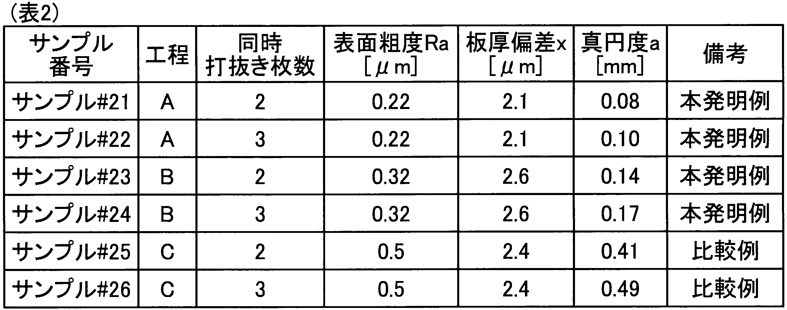
- Example 2 for the sample of the present invention and the sample of the comparative example, steps A, B, and C at the time of manufacturing the laminated core material described above, and the number of simultaneously punched electromagnetic steel sheets as the laminated core material, The influence of the surface roughness Ra and the plate thickness deviation x of the electrical steel sheet as the laminated core material on the roundness a as the iron core shape after punching was evaluated. The evaluation results are shown in Table 2.
- samples # 21 to # 24 are samples of the present invention example.
- Samples # 25 and # 26 are samples of comparative examples.
- FIG. 8 is a diagram showing the influence of the manufacturing process of the electrical steel sheet as the laminated core material and the roundness of the punched iron core shape as the shape of the core after punching.
- the surface roughness Ra of the steel plate 11 is adjusted to 0.40 [ ⁇ m] or less by performing the step A or the step B, and the plate thickness deviation x is set to the plate.
- the width direction D1 can be adjusted to 3 [ ⁇ m] or less per 500 [mm].
- Example 3 a third embodiment of the present invention will be described.
- Example 3 0.002 [mass%] carbon (C), 2.5 [mass%] silicon (Si), 0.70 [mass%] aluminum, and 0.05 [mass%] in steel.
- Mn manganese
- S sulfur
- N nitrogen
- Hot-rolled to a thickness of 2.0 [mm] the obtained hot-rolled steel sheet was annealed at a temperature of 950 [° C.], the hot-rolled steel sheet after this annealing was pickled, and the steel sheet 10 as the material Manufactured.
- Example 3 such a steel plate 10 is cold-rolled by a tandem cold rolling mill 21 (see FIG. 3) so that the plate thickness is 0.20 [mm].
- a steel plate 11 was produced.
- the rolling rolls 22a and 22b of the last rolling mill 22 in the tandem cold rolling mill 21 had a roll surface roughness of 0.3 [ ⁇ m] in terms of arithmetic average roughness Ra.
- the steel plate 11 was subjected to finish annealing at a temperature of 750 [° C.] to produce an electromagnetic steel plate as the steel plate 11 as a laminated core material.
- the steel plate 11 of Example 3 obtained as described above was obtained by measuring the surface roughness Ra and the plate thickness deviation x in the same manner as in Example 1 described above.
- Example 3 two sheets of the steel plate 11 after measuring the surface roughness Ra and the plate thickness deviation x are supplied to the punching device 4 (see FIG. 4) and overlapped with each other.
- Rolling oil was applied to the surface of the steel plate 11.
- the ratio of the application area of the rolling oil to the surface of the steel plate 11 (hereinafter referred to as the rolling oil application area ratio) was changed within a range of 0 to 100 [%] on the entire surface of the steel plate 11.
- the two steel plates 11 after the rolling oil application are pressed and brought into close contact with each other in the plate thickness direction D2 by the pressing portion 44, and the two steel plates 11 that are in close contact with each other are pressed by the press 45.
- Example 3 It was simultaneously punched into a ring shape with ⁇ a of 80 [mm] and inner diameter ⁇ b of 60 [mm]. As described above, the sample of the example of the present invention in Example 3 was manufactured. Thereafter, the roundness a of the sample of the present invention in Example 3 was determined in the same manner as in Example 1 described above.
- Example 3 with respect to the sample of the present invention example, the rolling oil application area ratio [%], the surface roughness Ra of the electromagnetic steel sheet as the laminated core material, and the plate thickness deviation x are as the core shape after punching.
- the influence on the roundness a was evaluated.
- the evaluation results are shown in Table 3.
- samples # 31 to # 36 are samples of the present invention example.
- FIG. 9 is a figure which shows the influence which the rolling oil application
- the surface roughness Ra is 0.40 [ ⁇ m] or less
- the plate thickness deviation x is 3 [ ⁇ m] or less per 500 [mm] in the plate width direction D1.
- the roundness a is reduced by applying rolling oil to the superposed steel plates 11. From this, after appropriately adjusting the surface roughness Ra and the plate thickness deviation x of the steel plate 11 as the laminated core material to values within the requirement range of the present invention, the steel plates 11 are overlapped in the plate thickness direction D2. It can be seen that the shape of the iron core after the punching process is further improved by applying rolling oil to the shell.
- the surface roughness of a steel sheet forming a laminated core material that is punched by being overlapped when a laminated core is manufactured is 0.40 [arithmetic mean roughness Ra]. [mu] m] or less, and the thickness deviation in the plate width direction of at least the portion used as the laminated iron core of the steel sheets constituting the laminated core material is 3 [[mu] m] or less per 500 [mm].
- the present invention it is possible to realize a steel sheet excellent in the punching process of a target iron core shape as a laminated core material.
- a steel sheet As a laminated core material, the steel sheets are stacked in the thickness direction.
- difference from the target iron core shape of the several punching body obtained by stamping the several steel plate simultaneously can be suppressed.
- a high space factor of the laminated core can be ensured, and as a result, an excellent laminated core with low energy loss can be manufactured.
- the value obtained by multiplying the thickness deviation of the steel sheet as the laminated core material by 0.05 and the surface roughness of the steel sheet is set to less than 0.5. For this reason, the synergistic effect of the effect by the surface roughness reduction of the steel plate mentioned above and the effect by plate thickness deviation reduction can be acquired. As a result, since the intrusion of air between the overlapping surfaces of a plurality of steel plates can be further suppressed, the punching shape of the steel plate as the laminated core material can be further improved.
- an oily agent such as rolling oil is applied to a plurality of steel plates stacked in the thickness direction as a laminated core material. For this reason, these piled-up several steel plates can be stuck more strongly by the press of a plate
- the material for a laminated core and the method for producing the laminated core in the case of manufacturing a ring-shaped laminated core have been described, but the present invention is not limited to this.
- the laminated core material and the laminated core manufacturing method according to the present invention may be for manufacturing a laminated core having a shape other than a ring shape such as a rectangular shape. That is, in the present invention, the shape of the manufactured laminated core (target core shape) is not particularly limited.
- the use of the manufactured laminated iron core is not limited to that for an electric motor, and is not particularly limited.
- the present invention is not limited to this.
- the number of steel plates to be stacked in the thickness direction as the laminated core material may be plural (two or more).
- the electromagnetic steel sheet is exemplified as the laminated core material, but the present invention is not limited to this.
- the steel plate as the laminated core material according to the present invention is not limited to an electromagnetic steel plate, and may be a steel plate other than the electromagnetic steel plate, or may be an iron alloy plate other than the steel plate.
- the present invention is not limited to the above-described embodiments and examples, and the present invention includes a configuration in which the above-described constituent elements are appropriately combined.
- all other embodiments, examples, operation techniques, and the like made by those skilled in the art based on the above-described embodiments and examples are included in the present invention.
- the laminated core material and the laminated core manufacturing method according to the present invention are useful for the production of laminated cores, and in particular, ensure a good punched shape and realize a high space factor laminated core. It is suitable for a laminated core material that can be manufactured and a method for producing a laminated core.
Landscapes
- Engineering & Computer Science (AREA)
- Chemical & Material Sciences (AREA)
- Physics & Mathematics (AREA)
- Power Engineering (AREA)
- Materials Engineering (AREA)
- Mechanical Engineering (AREA)
- Metallurgy (AREA)
- Organic Chemistry (AREA)
- Crystallography & Structural Chemistry (AREA)
- Thermal Sciences (AREA)
- Manufacturing & Machinery (AREA)
- Electromagnetism (AREA)
- Manufacture Of Motors, Generators (AREA)
- Manufacturing Cores, Coils, And Magnets (AREA)
Abstract
Description
まず、本発明の実施の形態にかかる積層鉄心用材料を用いて積層鉄心を製造する積層鉄心製造装置の構成について説明する。図1は、本発明の実施の形態における積層鉄心製造装置の一構成例を示す図である。本実施の形態において、積層鉄心製造装置1は、積層鉄心用材料としての鋼板11を用いて積層鉄心15を製造するものであり、積層鉄心製造ラインの一部をなす。このような積層鉄心製造装置1は、図1に示すように、冷延表面処理装置2と、焼鈍装置3と、打抜き加工装置4とを備える。なお、図1において、太線矢印は、鋼板10,11または積層鉄心15の搬送の流れを示す。
つぎに、本発明の実施の形態にかかる積層鉄心用材料について説明する。本発明の実施の形態にかかる積層鉄心用材料は、積層鉄心を製造する際に複数重ね合わせて打抜く鋼板として用いられる電磁鋼板等の高透磁率材である。本実施の形態において、この積層鉄心用材料としての鋼板11は、上述したように素材としての鋼板10の板厚、表面粗度、および板幅方向D1の板厚偏差を冷間圧延および表面処理によって調整することにより、製造される。すなわち、鋼板11は、冷間圧延前の鋼板10と同じ組成(例えば電磁鋼板としての組成)を有し、表面粗度および板幅方向D1の板厚偏差を鋼板10に比べて低減した薄鋼板である。
0.5>Ra+0.05×x ・・・(1)
つぎに、本発明の実施の形態における冷延表面処理装置2の構成について説明する。図3は、本発明の実施の形態における冷延表面処理装置の要部構成の一例を示す図である。本発明の実施の形態における冷延表面処理装置2は、素材としての鋼板10の冷間圧延および表面処理によって積層鉄心用材料を形成するものであり、図3に示すように、タンデム冷間圧延機21と、表面処理部25とを備える。
つぎに、本発明の実施の形態における打抜き加工装置4の構成について説明する。図4は、本発明の実施の形態における打抜き加工装置の要部構成の一例を示す図である。本発明の実施の形態における打抜き加工装置4は、積層鉄心用材料としての鋼板11に対して打抜き加工等を行って積層鉄心(例えば図2に示すリング形状の積層鉄心15)を形成するものである。図4に示すように、打抜き加工装置4は、ピンチロール42と、油性剤塗布部43と、押圧部44と、プレス機45とを備える。
つぎに、本発明の実施の形態にかかる積層鉄心の製造方法について説明する。図5は、本発明の実施の形態にかかる積層鉄心の製造方法の一例を示すフローチャートである。本発明の実施の形態にかかる積層鉄心の製造方法は、図5に示すステップS101~S107の各処理を順次行い、上述したように熱間圧延等の処理によって準備した鋼板10を積層鉄心用材料としての鋼板11に加工し、得られた鋼板11の打抜き加工等を行って積層鉄心15を製造するものである。
つぎに、本発明の実施例1について説明する。実施例1では、鋼中に0.002[mass%]の炭素(C)と3.6[mass%]の珪素(Si)と0.10[mass%]のアルミニウムと0.3[mass%]のマンガン(Mn)と0.0015[mass%]の硫黄(S)と0.002[mass%]の窒素(N)とを含有するスラブを、1100[℃]の温度で加熱した後、2.0[mm]の板厚まで熱間圧延し、得られた熱延鋼板を950[℃]の温度で焼鈍し、この焼鈍後の熱延鋼板を酸洗して、素材としての鋼板10を製造した。

つぎに、本発明の実施例2について説明する。実施例2では、鋼中に0.002[mass%]の炭素(C)と2.5[mass%]の珪素(Si)と0.70[mass%]のアルミニウムと0.05[mass%]のマンガン(Mn)と0.0020[mass%]の硫黄(S)と0.002[mass%]の窒素(N)とを含有するスラブを、1100[℃]の温度で加熱した後、2.0[mm]の板厚まで熱間圧延し、得られた熱延鋼板を950[℃]の温度で焼鈍し、この焼鈍後の熱延鋼板を酸洗して、素材としての鋼板10を製造した。
つぎに、本発明の実施例3について説明する。実施例3では、鋼中に0.002[mass%]の炭素(C)と2.5[mass%]の珪素(Si)と0.70[mass%]のアルミニウムと0.05[mass%]のマンガン(Mn)と0.0020[mass%]の硫黄(S)と0.002[mass%]の窒素(N)とを含有するスラブを、1100[℃]の温度で加熱した後、2.0[mm]の板厚まで熱間圧延し、得られた熱延鋼板を950[℃]の温度で焼鈍し、この焼鈍後の熱延鋼板を酸洗して、素材としての鋼板10を製造した。

2 冷延表面処理装置
3 焼鈍装置
4 打抜き加工装置
10,11,11a,11b,11c 鋼板
12 密着体
15 積層鉄心
21 タンデム冷間圧延機
22 最後段圧延機
22a,22b 圧延ロール
25 表面処理部
42 ピンチロール
43 油性剤塗布部
44 押圧部
45 プレス機
46 金型
46a パンチ
46b ダイ
47 ダイホール
48 ダイプレート
49 板押さえ
D1 板幅方向
D2 板厚方向
D3 長手方向
Claims (9)
- 積層鉄心を製造する際に複数重ね合わせて打抜く鋼板として用いられる積層鉄心用材料であって、
当該積層鉄心用材料をなす前記鋼板の表面粗度は、算術平均粗さRaで0.40[μm]以下であり、
当該積層鉄心用材料をなす前記鋼板のうちの少なくとも前記積層鉄心として用いられる部分の板幅方向の板厚偏差は、500[mm]あたり3[μm]以下であることを特徴とする積層鉄心用材料。 - 前記板厚偏差に0.05を乗じた値と前記表面粗度との加算値は、0.5未満であることを特徴とする請求項1に記載の積層鉄心用材料。
- 当該積層鉄心用材料をなす前記鋼板の板厚は、0.25[mm]以下であることを特徴とする請求項1または2に記載の積層鉄心用材料。
- 複数の鋼板を重ね合わせる重ね合わせステップと、
重ね合わせた前記複数の鋼板を同時に打抜いて、前記複数の鋼板の打抜き体を得る打抜きステップと、
前記打抜き体を積層し一体化して積層鉄心を形成する積層一体化ステップと、
を含み、
前記重ね合わせステップにおいて複数重ね合わせる前記鋼板の表面粗度は算術平均粗さRaで0.40[μm]以下であり、前記鋼板のうちの少なくとも前記積層鉄心として用いられる部分の板幅方向の板厚偏差は500[mm]あたり3[μm]以下であることを特徴とする積層鉄心の製造方法。 - 前記板厚偏差に0.05を乗じた値と前記表面粗度との加算値は、0.5未満であることを特徴とする請求項4に記載の積層鉄心の製造方法。
- 前記重ね合わせステップにおいて複数重ね合わせる前記鋼板の板厚は、0.25[mm]以下であることを特徴とする請求項4または5に記載の積層鉄心の製造方法。
- 重ね合わせた前記複数の鋼板をその板厚方向に押圧して、前記複数の鋼板同士の重ね合わせ面間に存在する空気を抜く押圧処理ステップをさらに含み、
前記打抜きステップは、前記重ね合わせ面間から空気が抜かれた後の前記複数の鋼板を同時に打抜くことを特徴とする請求項4~6のいずれか一つに記載の積層鉄心の製造方法。 - 重ね合わせた前記複数の鋼板に対して油性剤を塗布する塗布ステップをさらに含み、
前記押圧処理ステップは、前記油性剤を塗布後の前記複数の鋼板をその板厚方向に押圧することを特徴とする請求項7に記載の積層鉄心の製造方法。 - 重ね合わせ前の前記鋼板に対して冷間圧延および表面処理を行って、前記表面粗度を算術平均粗さRaで0.40[μm]以下に調整し且つ前記板厚偏差を500[mm]あたり3[μm]以下に調整する冷延表面処理ステップをさらに含み、
前記重ね合わせステップは、前記冷延表面処理ステップによって調整された前記表面粗度および前記板厚偏差を有する前記鋼板を複数重ね合わせることを特徴とする請求項4~8のいずれか一つに記載の積層鉄心の製造方法。
Priority Applications (5)
| Application Number | Priority Date | Filing Date | Title |
|---|---|---|---|
| EP15872427.8A EP3239998B1 (en) | 2014-12-26 | 2015-10-13 | Material for laminated iron core, and method of manufacturing laminated iron core |
| CN201580070278.9A CN107112124B (zh) | 2014-12-26 | 2015-10-13 | 层叠铁芯用材料及层叠铁芯的制造方法 |
| RU2017126623A RU2667141C1 (ru) | 2014-12-26 | 2015-10-13 | Материал для изготовления пластинчатого стального сердечника и способ производства пластинчатого стального сердечника |
| KR1020177016850A KR101909150B1 (ko) | 2014-12-26 | 2015-10-13 | 적층 철심의 제조 방법 |
| US15/538,459 US10927430B2 (en) | 2014-12-26 | 2015-10-13 | Material for laminated iron core, and method of manufacturing laminated iron core |
Applications Claiming Priority (2)
| Application Number | Priority Date | Filing Date | Title |
|---|---|---|---|
| JP2014265754A JP6587800B2 (ja) | 2014-12-26 | 2014-12-26 | 積層鉄心の製造方法 |
| JP2014-265754 | 2014-12-26 |
Publications (1)
| Publication Number | Publication Date |
|---|---|
| WO2016103858A1 true WO2016103858A1 (ja) | 2016-06-30 |
Family
ID=56149895
Family Applications (1)
| Application Number | Title | Priority Date | Filing Date |
|---|---|---|---|
| PCT/JP2015/078954 Ceased WO2016103858A1 (ja) | 2014-12-26 | 2015-10-13 | 積層鉄心用材料および積層鉄心の製造方法 |
Country Status (8)
| Country | Link |
|---|---|
| US (1) | US10927430B2 (ja) |
| EP (1) | EP3239998B1 (ja) |
| JP (1) | JP6587800B2 (ja) |
| KR (1) | KR101909150B1 (ja) |
| CN (1) | CN107112124B (ja) |
| RU (1) | RU2667141C1 (ja) |
| TW (1) | TWI594276B (ja) |
| WO (1) | WO2016103858A1 (ja) |
Families Citing this family (33)
| Publication number | Priority date | Publication date | Assignee | Title |
|---|---|---|---|---|
| JP6477550B2 (ja) * | 2016-03-11 | 2019-03-06 | Jfeスチール株式会社 | 積層鉄心の製造方法及び製造装置 |
| NL1042618B1 (en) * | 2017-11-02 | 2019-05-13 | Bosch Gmbh Robert | Multi-layer blanking process for manufacturing metal parts |
| KR102631738B1 (ko) | 2018-12-17 | 2024-02-01 | 닛폰세이테츠 가부시키가이샤 | 적층 코어, 적층 코어의 제조 방법 및 회전 전기 기기 |
| EP3902106B1 (en) | 2018-12-17 | 2025-10-29 | Nippon Steel Corporation | Adhesively laminated core for stator, method of manufacturing the same, and electric motor |
| TWI732384B (zh) | 2018-12-17 | 2021-07-01 | 日商日本製鐵股份有限公司 | 積層鐵芯及旋轉電機 |
| JP7515403B2 (ja) | 2018-12-17 | 2024-07-12 | 日本製鉄株式会社 | ステータ用接着積層コア、その製造方法、および回転電機 |
| SG11202108950YA (en) | 2018-12-17 | 2021-09-29 | Nippon Steel Corp | Adhesively-laminated core for stator and electric motor |
| WO2020129926A1 (ja) | 2018-12-17 | 2020-06-25 | 日本製鉄株式会社 | 積層コアおよび回転電機 |
| EP3902110B1 (en) | 2018-12-17 | 2026-01-28 | Nippon Steel Corporation | Laminated core and electric motor |
| RS66007B1 (sr) | 2018-12-17 | 2024-10-31 | Nippon Steel Corp | Laminirano jezgro i rotaciona električna mašina |
| EP3902120A4 (en) | 2018-12-17 | 2022-10-05 | Nippon Steel Corporation | STACKED CORE AND ROTATING ELECTRICAL MACHINE |
| EA202192064A1 (ru) | 2018-12-17 | 2021-11-24 | Ниппон Стил Корпорейшн | Шихтованный сердечник и электродвигатель |
| CN113228468B (zh) | 2018-12-17 | 2025-04-11 | 日本制铁株式会社 | 定子用粘接层叠铁芯、其制造方法及旋转电机 |
| TWI724690B (zh) | 2018-12-17 | 2021-04-11 | 日商日本製鐵股份有限公司 | 積層鐵芯及旋轉電機 |
| MY206339A (en) | 2018-12-17 | 2024-12-12 | Nippon Steel Corp | Laminated core, core block, electric motor and method of producing core block |
| KR102607691B1 (ko) | 2018-12-17 | 2023-11-30 | 닛폰세이테츠 가부시키가이샤 | 스테이터용 접착 적층 코어 및 회전 전기 기계 |
| CN113196634B (zh) | 2018-12-17 | 2024-10-18 | 日本制铁株式会社 | 层叠铁芯及旋转电机 |
| PL3902107T3 (pl) | 2018-12-17 | 2026-03-09 | Nippon Steel Corporation | Laminowany rdzeń, sposób jego wytwarzania i silnik elektryczny |
| JP7055209B2 (ja) | 2018-12-17 | 2022-04-15 | 日本製鉄株式会社 | 積層コアおよび回転電機 |
| EP3723249A1 (de) * | 2019-04-09 | 2020-10-14 | Siemens Aktiengesellschaft | Verfahren zur fertigung eines magnetblechs und eines magnetblechstapels sowie elektrische maschine und elektrisches fahrzeug |
| TWI709290B (zh) | 2019-09-26 | 2020-11-01 | 盟鑫金屬股份有限公司 | 電動車馬達之磁芯的製造方法 |
| TWI740714B (zh) * | 2019-11-15 | 2021-09-21 | 日商日本製鐵股份有限公司 | 積層鐵芯及電性機器 |
| CN110752720B (zh) * | 2019-11-29 | 2025-03-14 | 王晶 | 冲片冲切设备、片材的冲切方法及电机铁芯的制造方法 |
| CN110855103B (zh) * | 2019-11-29 | 2025-05-23 | 王晶 | 电机铁芯的制造设备及其制造方法 |
| WO2021124780A1 (ja) * | 2019-12-16 | 2021-06-24 | Jfeスチール株式会社 | モータコアおよびその製造方法 |
| JP2021158852A (ja) * | 2020-03-27 | 2021-10-07 | 日本電産株式会社 | 積層体製造装置及び積層体製造方法 |
| KR102664817B1 (ko) * | 2020-06-17 | 2024-05-10 | 닛폰세이테츠 가부시키가이샤 | 적층 코어의 제조 방법 |
| JP7694154B2 (ja) * | 2021-04-12 | 2025-06-18 | 株式会社アイシン | 金属薄片及び積層コアの製造装置並びに製造方法 |
| JP7292348B2 (ja) * | 2021-10-22 | 2023-06-16 | 三菱電機株式会社 | 回転電機の積層鉄心製造方法及び積層鉄心製造装置 |
| AU2023216067B2 (en) * | 2022-02-04 | 2026-01-15 | Nippon Steel Corporation | Wound Core Producing Apparatus and Wound Core Producing Method |
| WO2023149523A1 (ja) * | 2022-02-04 | 2023-08-10 | 日本製鉄株式会社 | 巻鉄心の製造装置および巻鉄心の製造方法 |
| JP2023181024A (ja) * | 2022-06-10 | 2023-12-21 | 株式会社日立製作所 | 積層鉄心の製造方法、積層鉄心、及び積層鉄心を用いた回転電機 |
| CN116470710B (zh) * | 2023-05-04 | 2024-12-20 | 常州宝捷冲片有限公司 | 一种u型铁芯压装检测浸油方法 |
Citations (6)
| Publication number | Priority date | Publication date | Assignee | Title |
|---|---|---|---|---|
| JPS54157214A (en) * | 1978-06-02 | 1979-12-12 | Shinko Electric Co Ltd | Method of producing iron core for electric appliances |
| JPS56103952A (en) * | 1980-01-18 | 1981-08-19 | Matsushita Electric Ind Co Ltd | Manufacture of iron core for motor |
| JPS5810445B2 (ja) * | 1979-07-16 | 1983-02-25 | 新日本製鐵株式会社 | 鉄損の優れた無方向性電磁鋼板の製造方法 |
| JPS58108935A (ja) * | 1981-12-23 | 1983-06-29 | Matsushita Electric Ind Co Ltd | 電動機の固定子鉄心及びその製造方法 |
| JP2001059145A (ja) * | 1999-06-16 | 2001-03-06 | Sumitomo Metal Ind Ltd | 無方向性電磁鋼板およびその製造方法 |
| JP2011139584A (ja) * | 2009-12-28 | 2011-07-14 | Jfe Steel Corp | モータコア |
Family Cites Families (20)
| Publication number | Priority date | Publication date | Assignee | Title |
|---|---|---|---|---|
| JPS62289302A (ja) * | 1986-06-09 | 1987-12-16 | Sumitomo Metal Ind Ltd | 金属帯のエツジドロツプ矯正方法 |
| JP3499956B2 (ja) * | 1995-01-09 | 2004-02-23 | 新日本製鐵株式会社 | 螺旋巻きした鋼板の積層部品 |
| JPH11176654A (ja) * | 1997-12-16 | 1999-07-02 | Kawasaki Steel Corp | アモルファス鉄心およびその製造方法 |
| JP2000173815A (ja) | 1998-12-09 | 2000-06-23 | Sumitomo Metal Ind Ltd | 積層鉄心用接着鋼板 |
| CN1102670C (zh) | 1999-06-16 | 2003-03-05 | 住友金属工业株式会社 | 无方向性电磁钢片及其制造方法 |
| JP4581228B2 (ja) | 2000-11-14 | 2010-11-17 | Jfeスチール株式会社 | 加工性に優れる積層電磁鋼板 |
| JP2003153503A (ja) | 2001-11-08 | 2003-05-23 | Matsushita Electric Ind Co Ltd | 電動機鉄心の製造方法 |
| JP2003163376A (ja) | 2001-11-29 | 2003-06-06 | Matsushita Electric Ind Co Ltd | 波長変換材料及び発光素子 |
| JP3771933B2 (ja) | 2002-03-08 | 2006-05-10 | Jfeスチール株式会社 | 積層コア用材料及びその製造方法 |
| JP3674599B2 (ja) * | 2002-05-02 | 2005-07-20 | 日本電産シバウラ株式会社 | 電動機鉄心、電動機及び電動機鉄心の製造方法 |
| JP2005191033A (ja) | 2003-12-24 | 2005-07-14 | Matsushita Electric Ind Co Ltd | 積層鉄心の製造方法 |
| JP2005332976A (ja) | 2004-05-20 | 2005-12-02 | Matsushita Electric Ind Co Ltd | 積層体の製造方法 |
| JP4798965B2 (ja) * | 2004-05-31 | 2011-10-19 | 株式会社東芝 | 回転機鉄心の製造方法 |
| JP2007221927A (ja) | 2006-02-17 | 2007-08-30 | Mitsubishi Electric Corp | 回転電機の固定子鉄心およびその製造方法 |
| JP2008228442A (ja) * | 2007-03-13 | 2008-09-25 | Hitachi Ltd | ステッピングモータ及びステッピングモータを製造する鋼板 |
| US9139886B2 (en) * | 2010-04-01 | 2015-09-22 | Nippon Steel & Sumitomo Metal Corporation | Grain-oriented electrical steel sheet and method for producing same |
| JP2011241160A (ja) | 2010-05-17 | 2011-12-01 | Yamamoto Chem Inc | 色変換材料、該材料を含む組成物、該組成物を使用した色変換光学部品および該色変換光学部品を使用した発光素子 |
| JP5810445B2 (ja) | 2010-09-03 | 2015-11-11 | 株式会社Flosfia | 多孔質体および濾過フィルタの製造方法 |
| JP5974671B2 (ja) * | 2011-11-09 | 2016-08-23 | Jfeスチール株式会社 | 極薄電磁鋼板 |
| CN105960714B (zh) | 2014-02-05 | 2018-02-09 | 东丽株式会社 | 光电转换元件及图像传感器 |
-
2014
- 2014-12-26 JP JP2014265754A patent/JP6587800B2/ja active Active
-
2015
- 2015-10-13 RU RU2017126623A patent/RU2667141C1/ru active
- 2015-10-13 US US15/538,459 patent/US10927430B2/en active Active
- 2015-10-13 KR KR1020177016850A patent/KR101909150B1/ko active Active
- 2015-10-13 WO PCT/JP2015/078954 patent/WO2016103858A1/ja not_active Ceased
- 2015-10-13 CN CN201580070278.9A patent/CN107112124B/zh active Active
- 2015-10-13 EP EP15872427.8A patent/EP3239998B1/en active Active
- 2015-11-17 TW TW104137917A patent/TWI594276B/zh active
Patent Citations (6)
| Publication number | Priority date | Publication date | Assignee | Title |
|---|---|---|---|---|
| JPS54157214A (en) * | 1978-06-02 | 1979-12-12 | Shinko Electric Co Ltd | Method of producing iron core for electric appliances |
| JPS5810445B2 (ja) * | 1979-07-16 | 1983-02-25 | 新日本製鐵株式会社 | 鉄損の優れた無方向性電磁鋼板の製造方法 |
| JPS56103952A (en) * | 1980-01-18 | 1981-08-19 | Matsushita Electric Ind Co Ltd | Manufacture of iron core for motor |
| JPS58108935A (ja) * | 1981-12-23 | 1983-06-29 | Matsushita Electric Ind Co Ltd | 電動機の固定子鉄心及びその製造方法 |
| JP2001059145A (ja) * | 1999-06-16 | 2001-03-06 | Sumitomo Metal Ind Ltd | 無方向性電磁鋼板およびその製造方法 |
| JP2011139584A (ja) * | 2009-12-28 | 2011-07-14 | Jfe Steel Corp | モータコア |
Also Published As
| Publication number | Publication date |
|---|---|
| JP6587800B2 (ja) | 2019-10-09 |
| TW201629997A (zh) | 2016-08-16 |
| KR20170088385A (ko) | 2017-08-01 |
| CN107112124A (zh) | 2017-08-29 |
| US20170342519A1 (en) | 2017-11-30 |
| JP2016127092A (ja) | 2016-07-11 |
| EP3239998A4 (en) | 2017-11-01 |
| KR101909150B1 (ko) | 2018-10-17 |
| EP3239998A1 (en) | 2017-11-01 |
| TWI594276B (zh) | 2017-08-01 |
| CN107112124B (zh) | 2019-05-14 |
| EP3239998B1 (en) | 2019-10-02 |
| RU2667141C1 (ru) | 2018-09-17 |
| US10927430B2 (en) | 2021-02-23 |
Similar Documents
| Publication | Publication Date | Title |
|---|---|---|
| JP6587800B2 (ja) | 積層鉄心の製造方法 | |
| US20090280338A1 (en) | Method for Lamination of an Electrical Strip for Transformer Cores | |
| CN107206457B (zh) | 冲裁加工方法、冲裁加工装置和层叠铁芯的制造方法 | |
| CN110168679A (zh) | 卷绕铁心及其制造方法 | |
| EP3205415A1 (en) | Method for producing metal plate with protruding ridge, metal plate with protruding ridge, and structural component | |
| TWI622437B (zh) | 疊層鐵心製造裝置及疊層鐵心製造方法 | |
| JP6805978B2 (ja) | 無方向性電磁鋼板およびその製造方法 | |
| KR20220028054A (ko) | 무방향성 전기강판 및 그 제조 방법 | |
| EP3345692B1 (en) | Laminated core manufacturing device and laminated core manufacturing method | |
| JP7469670B2 (ja) | 鉄心の製造方法および製造装置 | |
| US20090223269A1 (en) | Method and apparatus for continuously manufacturing metal sheets | |
| JP2017197806A (ja) | 高性能モータ用無方向性電磁鋼板 | |
| TWI846520B (zh) | 捲鐵心 | |
| TWI843613B (zh) | 捲鐵心 | |
| JP7778473B2 (ja) | 鉄心の製造方法および製造装置 | |
| JP2024065562A (ja) | 積層コアの製造方法 | |
| JPH0824968A (ja) | 金属プレス加工製品の製造方法 |
Legal Events
| Date | Code | Title | Description |
|---|---|---|---|
| 121 | Ep: the epo has been informed by wipo that ep was designated in this application |
Ref document number: 15872427 Country of ref document: EP Kind code of ref document: A1 |
|
| ENP | Entry into the national phase |
Ref document number: 20177016850 Country of ref document: KR Kind code of ref document: A |
|
| WWE | Wipo information: entry into national phase |
Ref document number: 15538459 Country of ref document: US |
|
| REEP | Request for entry into the european phase |
Ref document number: 2015872427 Country of ref document: EP |
|
| NENP | Non-entry into the national phase |
Ref country code: DE |
|
| ENP | Entry into the national phase |
Ref document number: 2017126623 Country of ref document: RU Kind code of ref document: A |