WO2016103921A1 - 情報処理装置 - Google Patents
情報処理装置 Download PDFInfo
- Publication number
- WO2016103921A1 WO2016103921A1 PCT/JP2015/081007 JP2015081007W WO2016103921A1 WO 2016103921 A1 WO2016103921 A1 WO 2016103921A1 JP 2015081007 W JP2015081007 W JP 2015081007W WO 2016103921 A1 WO2016103921 A1 WO 2016103921A1
- Authority
- WO
- WIPO (PCT)
- Prior art keywords
- data
- filter
- information processing
- unit
- processing apparatus
- Prior art date
- Legal status (The legal status is an assumption and is not a legal conclusion. Google has not performed a legal analysis and makes no representation as to the accuracy of the status listed.)
- Ceased
Links
Images


Classifications
-
- G—PHYSICS
- G09—EDUCATION; CRYPTOGRAPHY; DISPLAY; ADVERTISING; SEALS
- G09B—EDUCATIONAL OR DEMONSTRATION APPLIANCES; APPLIANCES FOR TEACHING, OR COMMUNICATING WITH, THE BLIND, DEAF OR MUTE; MODELS; PLANETARIA; GLOBES; MAPS; DIAGRAMS
- G09B29/00—Maps; Plans; Charts; Diagrams, e.g. route diagram
- G09B29/003—Maps
- G09B29/006—Representation of non-cartographic information on maps, e.g. population distribution, wind direction, radiation levels, air and sea routes
- G09B29/007—Representation of non-cartographic information on maps, e.g. population distribution, wind direction, radiation levels, air and sea routes using computer methods
-
- G—PHYSICS
- G01—MEASURING; TESTING
- G01C—MEASURING DISTANCES, LEVELS OR BEARINGS; SURVEYING; NAVIGATION; GYROSCOPIC INSTRUMENTS; PHOTOGRAMMETRY OR VIDEOGRAMMETRY
- G01C21/00—Navigation; Navigational instruments not provided for in groups G01C1/00 - G01C19/00
- G01C21/26—Navigation; Navigational instruments not provided for in groups G01C1/00 - G01C19/00 specially adapted for navigation in a road network
- G01C21/34—Route searching; Route guidance
- G01C21/36—Input/output arrangements for on-board computers
- G01C21/3626—Details of the output of route guidance instructions
- G01C21/3658—Lane guidance
-
- G—PHYSICS
- G01—MEASURING; TESTING
- G01C—MEASURING DISTANCES, LEVELS OR BEARINGS; SURVEYING; NAVIGATION; GYROSCOPIC INSTRUMENTS; PHOTOGRAMMETRY OR VIDEOGRAMMETRY
- G01C21/00—Navigation; Navigational instruments not provided for in groups G01C1/00 - G01C19/00
- G01C21/26—Navigation; Navigational instruments not provided for in groups G01C1/00 - G01C19/00 specially adapted for navigation in a road network
- G01C21/34—Route searching; Route guidance
- G01C21/36—Input/output arrangements for on-board computers
- G01C21/3679—Retrieval, searching and output of POI information, e.g. hotels, restaurants, shops, filling stations, parking facilities
-
- G—PHYSICS
- G09—EDUCATION; CRYPTOGRAPHY; DISPLAY; ADVERTISING; SEALS
- G09B—EDUCATIONAL OR DEMONSTRATION APPLIANCES; APPLIANCES FOR TEACHING, OR COMMUNICATING WITH, THE BLIND, DEAF OR MUTE; MODELS; PLANETARIA; GLOBES; MAPS; DIAGRAMS
- G09B29/00—Maps; Plans; Charts; Diagrams, e.g. route diagram
Definitions
- the present invention relates to an information processing apparatus that controls the reading range of map information.
- Patent Document 1 discloses an apparatus that controls the acquisition of map data for road regulation and the like in accordance with the passing direction of a vehicle with respect to a regulation point set by a user.
- Necessary information in the map information differs between various applications of the vehicle for performing automatic driving and driving support.
- the necessary information in the map information may differ depending on the situation of the vehicle.
- the capacity of information that can be read may be limited, and it is also required to select necessary information from map information and reduce the load related to acquisition of map information.
- the present invention provides a technique for controlling the reading range of map information.
- the present application includes a plurality of means for solving the above-mentioned problems.
- a route planning unit that generates route data to a certain target destination, and a filter indicating an acquisition range for map data.
- An information processing apparatus includes a filter setting unit that sets the range, and a map data acquisition unit that acquires data in the range set by the filter from the map data.
- the information processing apparatus receives sensor data from a sensor unit, and generates a route data to a target destination, specification data of the sensor unit, and the route data.
- An information processing apparatus comprising: a filter setting unit that sets a filter indicating an acquisition range for map data; and a map data acquisition unit that acquires data in the range set by the filter from the map data.
- FIG. 1 is a schematic configuration diagram of a vehicle according to a first embodiment. It is a flowchart which shows the process of the controller part which concerns on 1st Example. It is a flowchart which shows the filter setting process of the controller part which concerns on 1st Example. A certain intersection and a plurality of road links at the intersection are shown. It is an example of the structure of the map data showing the content of FIG. It is an example of the structure of the map data showing the content of FIG. 3, Comprising: It is a figure which shows the continuation from FIG. 4A. It is a figure explaining the other example of a filter setting process. It is the figure which extracted a part of FIG. 4A, and is a figure explaining the other example of control of the acquisition range of map data. It is a schematic block diagram of the vehicle which concerns on 2nd Example. It is a flowchart which shows the process of the controller part which concerns on 2nd Example. It is a figure explaining the filter setting process of the controller part which concerns on 2nd Example.
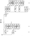
- FIG. 1 shows a configuration of a vehicle according to the first embodiment.
- the vehicle 101 includes a controller unit 102, a sensor unit 103, a movement mechanism unit 104, a communication unit 105, and a data storage unit 106.
- the controller unit 102 is an information processing apparatus including a processor, a memory, and the like (not shown).
- the processor executes processing corresponding to each component of the controller unit 102 described below in accordance with an instruction of a program stored in the memory. That is, each component of the controller unit 102 can be realized as software.
- each component in the controller unit 102 is assumed to be implemented as software, and the other portions are assumed to be implemented as hardware. Of these, one of each component in the controller unit 102 is assumed to be implemented. You may implement a part or all as hardware.
- the sensor unit 103 includes a stereo camera and a GPS. Therefore, the sensor unit 103 has a function of measuring the position, posture, and surrounding environment of the vehicle 101. If the same function is satisfied, the sensor unit 103 may be configured by another sensor such as a laser scanner. Further, the sensor unit 103 may be configured by other sensors as long as the state recognition can be performed by processing in the state recognition unit 107 described later.
- the moving mechanism unit 104 is a component for moving the vehicle 101, such as an engine, a brake, and a steering mechanism.
- the controller unit 102 calculates a target value (engine and brake target values) of the moving mechanism unit 104, and the moving mechanism unit 104 is controlled based on the calculated value.
- the communication unit 105 has a function of acquiring the traffic regulation data 115 and the map data 116 from an external server.
- the data storage unit 106 stores traffic regulation data 115 and map data 116.
- the data storage unit 106 is a hard disk drive.
- the communication unit 105 acquires the traffic regulation data 115 and the map data 116 and records them in the data storage unit 106.
- the communication unit 105 is not provided and the data storage unit 106 is preliminarily provided. A configuration in which the traffic regulation data 115 and the map data 116 are all recorded may be used.
- the traffic regulation data 115 is information relating to traffic regulations to be protected on the target road.
- traffic regulations data 115 such as speed limit, entry to the opposite lane, one-way street, right / left turn prohibition, temporary stop, etc., but in the following example, from the right turn lane in the intersection It is assumed that the laws and regulations prohibiting entry into the lane are dataized.
- the map data 116 is information relating to a vehicle route (a route assumed to be traveled by a vehicle).
- the map data 116 includes route information, route shape information, and route attribute information, and these pieces of information are associated with each other.
- map data 116 and the traffic regulation data 115 are described as separate data, but the present invention is not limited to this.
- the map data 116 may include speed limit information as road markings. Therefore, the map data 116 and the traffic regulation data 115 may be implemented by a single integrated data structure, or may be implemented in a form in which some overlap.
- the route information of the map data 116 is a graph composed of road link information corresponding to the center line of each lane of the roadway and intersection information (node information) corresponding to the end point (intersection) of the roadway section. Expressed in structure. Note that the map data 116 is not limited to such a graph structure, and may be expressed in another structure.
- the route shape information is data for specifying the shape of the road link and the intersection described above, and is information that can specify, for example, the width of the road, the outer shape, and the like.
- the attribute information is various information other than the shape information on the route, and is, for example, information such as road signs, road markings, paint identifying each lane of the roadway, and terrain.
- Information on road signs and road markings includes coordinate information, outer shape, color, pattern, and the like.
- the map data 116 is information (signals, median strips, pedestrian bridges) installed on or along the roadway, and information on the environment around the roadway (the sidewalks around the roadway and the architecture around the roadway) Information such as things).
- the controller unit 102 includes a sensor control unit 112, a state recognition unit 107, a route planning unit 108, a traffic regulation data acquisition unit 113, a filter setting unit 109, a map data acquisition unit 110, a map buffer 114, and a control. Unit 111.
- the sensor control unit 112 has a function of acquiring sensor data obtained by measuring the position, posture, and surrounding environment of the vehicle 101 by controlling the sensor unit 103.
- the state recognition unit 107 has a function of recognizing the position and posture of the vehicle and the running lane based on the sensor data obtained from the sensor unit 103.
- the route planning unit 108 has a function of generating route data to the destination based on the current vehicle position obtained from the state recognition unit 107, a separately set destination, and the map data 116.
- the traffic regulation data acquisition unit 113 has a function of acquiring the traffic regulation data 115 obtained via the communication unit 105 from the data storage unit 106 into the controller unit 102.
- the filter setting unit 109 is data indicating the acquisition range of the map data 116 (hereinafter, “ Filter).
- the map data acquisition unit 110 acquires the map data 116 from the data storage unit 106, acquires only necessary information from the map data 116 based on the filter set by the filter setting unit 109, and stores it in the map buffer 114 Is provided. Various types of information of the map data 116 are selected based on the filter, and information on the selected map data is stored in the map buffer 114. Information stored in the map buffer 114 is used by the state recognition unit 107, the route planning unit 108, the control unit 111, and the like.
- the route planning unit 108 generates route data based on the map data stored in the map buffer 114 and sends the route data to the control unit 111.
- the control unit 111 generates control values (engine and brake target values) of the moving mechanism unit 104 and controls the moving mechanism unit 104 based on these control values.
- controller unit 102 the sensor unit 103, and the like are mounted as separate hardware, but the entire or part of any hardware is mounted so as to be built in other hardware. May be.
- each component other than the sensor unit 103 and the moving mechanism unit 104 may be partially in a remote place as long as communication is possible.
- the hardware and software which comprise each said component may perform the selection according to embodiment.
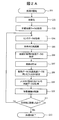
- FIG. 2A is a flowchart showing processing of the controller unit 102.
- the functional block of FIG. 1 will be described as a subject.
- the program performs processing determined by being executed by the processor using a memory, a communication port, and the like, the description will be made with the processor as the subject. Also good.
- the controller unit 102 executes an initialization process (202).
- the sensor control unit 112 acquires sensor data from the sensor unit 103.
- the map data acquisition unit 110 acquires the surrounding map data 116 and records it in the map buffer 114.
- state recognition processing by the state recognition unit 107 is performed.
- the state recognition unit 107 recognizes the position and orientation of the vehicle 101 and the lane in which the vehicle 101 is located by map matching of the position to map data using GPS. By the processing so far, the position and posture of the vehicle 101 on the map and the lane where the vehicle 101 is located can be recognized.
- the controller unit 102 acquires destination information.
- a method of acquisition a method for acquiring a destination specified by the user in a car navigation system is conceivable.
- a destination is automatically selected from a past destination history or a destination candidate such as a tourist destination or a restaurant. You may make it set to.
- another method may be used as long as the destination is set.
- the traffic regulation data acquisition unit 113 acquires the traffic regulation data 115 from the data storage unit 106 (203).
- the sensor control unit 112 acquires sensor data from the sensor unit 103 (204). Further, based on the sensor data, the state recognition unit 107 recognizes the position and posture of the vehicle 101 and the running lane (205).
- the map data acquisition unit 110 acquires map data for route planning from the data storage unit 106 based on the current position recognized by the state recognition unit 107 (206).
- the map data for route planning here includes only road link information, intersection information (road links and coordinates of intersections, etc.) and data relating to their connection relationship. That is, the map data for route planning does not include detailed data such as the shape information and attribute information described above, and assumes minimum data necessary for route planning.
- the route planning unit 108 uses the map data acquired for route planning to plan a route from the current position to the destination (207).
- map data acquired for route planning to plan a route from the current position to the destination (207).
- arc distance calculation and shortest path search based on this are performed.
- the route planning unit 108 outputs, as route data, data related to the road link obtained by the route search and the order of tracing the road link.
- the filter setting unit 109 sets a filter based on the route data and traffic regulation data 115 obtained so far (208).
- the filter is data indicating the acquisition range of the map data 116, and more specifically, whether or not each data (route information, shape information, attribute information, etc.) included in the map data 116 is acquired for each data. It becomes the data of the flag which shows.
- the map data acquisition unit 110 acquires only necessary information from the map data 116 based on the filter set by the filter setting unit 109 (209).
- the map data acquisition unit 110 stores the acquired map data in the map buffer 114.
- control unit 111 generates target values for the engine and the brake based on the map data obtained so far (information stored in the map buffer 114) and the route data, and based on these target values.
- the moving mechanism unit 104 is controlled (210).
- the control unit 111 calculates the curvature of the curve by using the map data (information stored in the map buffer 114), and performs control such as applying a brake until the vehicle can travel safely.
- control unit 111 calculates the distance between the current position and the destination, and determines whether the destination has been reached (211). If the distance is greater than the threshold, it is determined that the destination has not been reached, and a series of processing is repeated. If it is determined that the vehicle has arrived, the automatic driving process assumed here ends (212).
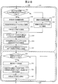
- FIG. 2B is a flowchart showing the filter setting process of the controller unit 102, and is a detailed flowchart of step 208 in FIG. 2A.
- the filter setting process is roughly divided into an area filter setting process (227) and a rule filter setting process (228).
- the area filter is a filter indicating a range when the vehicle operates according to route data. When the road filter and the like are physically within a predetermined range based on the coordinates of the road link forming the route and the intersection connected to the area filter, the area filter displays the attribute information corresponding to them in the map data 116. It is for setting to get from.
- the rule filter is a filter that indicates the range of operation of the vehicle 101 in accordance with the traffic regulation data 115. That is, the rule filter is for setting so as to acquire from the map data 116 information on a range necessary for the operation of the vehicle in accordance with the traffic regulations based on the predetermined traffic regulations data 115.
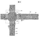
- FIG. 3 shows a certain intersection and a plurality of road links connected to the intersection.
- the description will be made on the assumption that the vehicle 304 that has traveled straight upward from the lower side in FIG. 3 turns right at the intersection.
- FIG. 4A and 4B are examples of the structure of the map data 116 representing the contents of FIG. 4A and 4B do not describe all of the map data corresponding to FIG. 3, but simply show it for explanation.
- the map data 116 is implemented as a “road link / intersection management table”.
- the structure of the map data 116 is not limited to this format. Note that the reference numeral “A” in FIG. 4A is shown as following the reference numeral “A” in FIG. 4B.
- the “road link shape” corresponds to, for example, road link information corresponding to the center line of each lane of the roadway.
- the “road outline coordinates” correspond to route shape information.
- “Road sign”, “road marking”, and the like correspond to route attribute information.
- the vehicle 304 moves from the road link 301 according to the route data moving to the road link 303 via the road link 302 that turns right inside the intersection.
- the road link 301 corresponds to the road link A (401) in FIG. 4A.
- the road link 302 corresponds to the road link B (402) in FIG. 4B.
- the road link 303 corresponds to the road link C (403) in FIG. 4A.
- the road link 308 corresponds to the road link D (404) in FIG. 4B.
- all the road map elements in FIG. 3, for example, road markings are not shown in FIG. 4A and FIG. 4B, but are omitted.
- the structure of the map data 116 may not be the structure of FIGS. 4A and 4B, and may be a structure in which data such as road markings are in the same hierarchy as the road links.
- the filter setting unit 109 determines whether or not an intersection is associated with a road link that forms a route on which the vehicle is to travel. (213).
- the intersection data 405 in this case, the intersection data entity 407 can be acquired from the data 405) included in the data of the road link B (402) in FIG. 4B.
- the intersection data can be referred to from the road link data. This refers to the case where the road link is within the intersection, such as the road link 302 of FIG.
- the filter setting unit 109 checks the presence or absence of intersection data for a road link.
- the filter setting unit 109 acquires the road outline coordinates of the road link (217). For example, for road link 301, data of road outline coordinates 406 (FIG. 4A) is acquired.
- the road contour coordinates are vertex coordinates of polygons provided so as to include road links.
- the filter setting unit 109 sets the area based on the vertex coordinates as an area filter (218). For example, for the road link 301, the area filter is set like a dotted frame 305 in FIG. Similarly, since the road link 303 is not included in the intersection, an area filter is set as shown by a dotted frame 307 in FIG.
- the filter setting unit 109 acquires intersection outline coordinates of an intersection that can be referred to from the road link (214). For example, for road link 302, data of intersection outline coordinates 408 (FIG. 4B) is acquired.
- the intersection external coordinates are the vertex coordinates of a polygon provided so as to include the intersection.
- the filter setting unit 109 sets the area based on the vertex coordinates as an area filter (215). For example, for the road link 302, the area filter is set as indicated by a dotted frame 306 in FIG.
- the area to be an area filter is determined from road outline coordinates or intersection outline coordinates recorded in the map data 116, but based on the road link shape or the like (for example, 411 in FIG. 4A) A method of calculating vertex coordinates that form an area in the field may be used.
- This intersection flag is a flag indicating that an intersection is associated with a road link.
- the filter setting unit 109 acquires the outer coordinates of the object based on the object table corresponding to the road link (219).
- the object here refers to map data having outline coordinates in the map data 116 in particular.
- the object is not limited to information associated with an intersection or road link.
- the objects here may be all objects having an outer shape (outer coordinates) in the map data, such as some installations or buildings around road links or intersections.
- the object table is data held for each intersection or road link, and is data indicating the relationship between the object and the intersection or road link. For example, an object associated with the road link and a connection relationship between the road link and each object are recorded in the road link object table. By referring to this object table, it is possible to determine what objects (road markings, road signs, etc.) exist in the road link.
- the filter setting unit 109 acquires the external coordinates of the object associated with the road link based on this object table. For example, in the case of the road link A (401) in FIG.
- the filter setting unit 109 searches for an object within the area filter range from the outer coordinates of each object and the vertex coordinates of the area filter (220).
- the filter setting unit 109 creates a list of objects within the area filter range.
- the filter setting unit 109 sets the data acquisition flag to ON for the object determined to be in the area filter (221).
- the data acquisition flag is data added to each individual data in the map data as indicated by 409 in FIG. 4A.
- the data acquisition flag is defined as 1 being on and 0 being off.
- the data acquisition flag 409 is 1, it is an object of acquisition as map data, and when it is 0, it indicates that it is not an object of acquisition of map data.
- the map data acquisition range based on the route data is set.
- the acquisition range of the map data based on the traffic regulation data 115 is set.
- a rule filter is set based on a law that prohibits entry from a right turn lane to another lane in an intersection.
- the filter setting unit 109 determines whether or not the road link is in the intersection (222). This is performed based on the intersection flag in step 216. When the intersection flag is off, the road link is not in the intersection, so that the processing based on the regulations in the intersection is not performed and the subsequent processing proceeds.
- the filter setting unit 109 performs processing based on the regulations in the intersection.
- the filter setting unit 109 determines a running lane (223).
- the filter setting unit 109 can acquire information on the running lane from the state recognition unit 107. Now, as shown in FIG. 3, it is assumed that the vehicle 304 is traveling on a right turn exclusive lane.
- the filter setting unit 109 sets the data acquisition flag for the road link other than the road link corresponding to the right turn exclusive lane and the related data to off (224). For example, if the vehicle 304 is traveling in the position shown in FIG. 3 and is in a right turn exclusive lane, that is, if there is no other way to make a right turn at the next intersection, within the range of the area filter 306 Even so, the data acquisition flag of the map data of the road link 308 that is not connected to the road link 302 (that is, cannot enter) is set to OFF. That is, the data acquisition flag of the road link D (404) in FIG. 4B is set to off. As a result, in the area filter 306, data such as the road link 308 that cannot be entered from the road link 302 and the road markings associated therewith are not acquired. Finally, the filter setting unit 109 sets the intersection flag to OFF (225).
- step (223) for determining the current lane is performed, but this step may be changed or deleted as appropriate.
- the determination of the current lane may not be performed, the route data may be compared, and the map data acquisition flag for the road link 308 that is not on the route data may be set to off.
- the map data acquisition unit 110 only requires necessary information from the map data 116 (that is, information for which the data acquisition flag is set to ON) based on the area filter and rule filter set by the filter setting unit 109. To get. Thereby, the map data actually acquired in the map buffer 114 of the controller unit 102 is reduced with respect to the entire map data 116.
- rule filter setting processing may be implemented in accordance with applicable laws and regulations. For example, in order to prohibit entry into the oncoming lane, one-way traffic, right turn / left turn prohibition, etc., the data acquisition flag for information relating to road links that cannot be entered from the current lane of the vehicle may be set off.
- the data acquisition flag of the speed limit 431 in FIG. 4A may be turned on to acquire information. Based on the information, the control unit 111 may control the moving mechanism unit 104 to adjust the speed of the vehicle 101.
- the control unit 111 can also control the moving mechanism unit 104 to stop the vehicle 304 at the position of the stop line by automatic driving. At this time, the control unit 111 may stop the vehicle 304 at the position of the stop line based on the sensor data from the sensor unit 103 and the current position from the state recognition unit 107.
- map data to be acquired is reduced by sequentially setting the area filter and the rule filter.
- the area filter or the rule filter is implemented or the order of these is changed. May be implemented.
- FIG. 5 is a diagram for explaining another example of the filter setting process.
- information on the road link related to the route data on which the vehicle is scheduled to travel is acquired.
- FIG. 5 is a diagram assuming a case where the vehicle 304 makes a right turn at an intersection as in FIG. 3. In this case, since the portion of the dotted line frame 501 is a road link that does not follow the route data of the vehicle 304, data acquisition is not performed.
- the portion of the dotted line frame 502 in FIG. 5 is the opposite lane with respect to the traveling direction of the vehicle 304, and thus data is not acquired based on the route data and the traffic regulation data 115.
- the filter setting unit 109 may set a filter on all or part of the dotted frame 502 to acquire map data.
- the vehicle 304 when it is assumed that a parked vehicle or an obstacle exists on the road link on the route data and the vehicle 304 makes a detour to avoid it, the vehicle 304 is in an adjacent lane (a lane opposite to the dotted frame 502). Will protrude slightly. Therefore, when map data for an emergency avoidance application is assumed, a filter is set for all or part of the dotted frame 502 by the filter setting unit 109, so that the emergency avoidance application protrudes next to the lane being traveled. It is possible to determine that there is a lane that may be present, and the vehicle 304 can be detoured.
- the filter setting unit 109 sets not only a strict range along the route data but also an operable range when the vehicle operates along the route data, as a filter, according to the type of application or the situation of the vehicle. It's okay. In other words, information on lanes (road links) that are not related to route data on which the vehicle is scheduled to travel may be acquired according to the type of application or the situation of the vehicle.
- a filter may be set in consideration of a portion that cannot be driven.
- a dotted line frame 503 in FIG. 5 indicates a central separation band, and the vehicle 304 cannot travel.
- the filter setting unit 109 may acquire data by setting a filter in a portion other than the dotted line frame 503.
- the emergency avoidance application can determine that there is a region where the vehicle cannot travel next to the traveling lane, and can control the vehicle 304 to stop when a parked vehicle or the like is present.
- the filter setting unit 109 may set a filter so that detailed information (for example, attribute information) of this area is not acquired based on the area where the dotted frame 503 cannot travel.
- the filter setting unit 109 may control the acquisition of attribute information in the map data according to the type of application or the situation of the vehicle.
- the dotted line frame 504 in FIG. 5 has a road marking drawn on the road surface. Depending on the type of application or the situation of the vehicle, whether or not to acquire detailed information on the road marking is changed. Good.
- FIG. 6 is an excerpt of the road link A (401) in FIG. 4A, and is a diagram for explaining another example of the control of the acquisition range of the map data.
- the range in which the filter setting unit 109 sets the data acquisition flag to ON in the road link A (401) related to the route data on which the vehicle travels is set according to the type of application. You may control.
- the example in which the data acquisition flag for the speed limit is turned off is shown, but the reverse case is also conceivable. For example, in a situation where the vehicle is driving on a highway, i.e., it is only necessary to drive along the current lane, only the speed limit information is obtained from the map data, and the automatic driving application Adjustments may be made.
- the filter setting unit 109 may control the filter range between a plurality of hierarchies or within the same hierarchy in the hierarchized data structure.
- the filter setting unit 109 may control which level of information is acquired in the road link A (401), and may control which information is acquired in the same level.
- the data acquisition flag of “detailed shape / color” is set off in the information of the same hierarchy related to the road marking.
- the range of the map data acquired by the controller unit 102 can be narrowed down. Therefore, it is possible to reduce a load related to acquisition of map data by a moving body such as the controller unit 102 or the vehicle 101.
- a filter indicating the acquisition range of map data can be set to narrow the range of information acquired from the map information.
- the filter can be set from information such as the lane in which the vehicle 101 is currently traveling.
- road map information and road marking information necessary for position estimation are acquired from map data, and high-precision vehicle position estimation is also performed in cooperation with the sensor unit 103. Is possible.
- detailed information related to driving is acquired from map data such as speed limit, stop line, curve curvature, slope difference, and the control unit 111 moves the moving mechanism unit 104. It can also be controlled.
- the capacity of the map data is reduced, when the map data is acquired by the controller unit, processing by the controller unit having only a slower device or network is possible.
- the vehicle controller unit can be mounted using a low-speed device or network, the cost is reduced.
- FIG. 7 shows a configuration of a vehicle according to the second embodiment.
- the same components as those of FIG. 7 are identical to FIG. 7 and the same components as those of FIG. 7;
- the data storage unit 106 stores sensor specification data 702.
- the sensor specification data is information that defines a range that can be measured by the sensor unit 103, such as a viewing angle of the sensor unit 103, a measurement distance in the depth direction that can be measured by the sensor unit 103, and the like.
- the controller unit 102 includes a sensor specification data acquisition unit 701.
- the sensor specification data acquisition unit 701 acquires the sensor specification data 702 from the data storage unit 106 and sends it to the filter setting unit 109.
- FIG. 8 is a flowchart showing the processing of the controller unit 102 according to the second embodiment.
- the filter setting unit 109 sets an area filter based on the route data and sensor specification data (801).
- FIG. 9 is a diagram for explaining the area filter setting.
- Reference numeral 901 denotes a line indicating the route data output in step 207 of FIG.
- the filter setting unit 109 calculates a range that can be measured by the sensor unit 103 based on the sensor specification data 702 (viewing angle, measurement distance in the depth direction, and the like).
- An area 902 indicated by a sector indicates a range that can be measured by the sensor unit 103 calculated based on the sensor specification data 702.
- the range measurable by the sensor unit 103 is an area surrounded by a dotted line 903.
- the filter setting unit 109 calculates a range that can be measured by the sensor unit 103 when the vehicle 101 travels on the route data 901 along the route.
- the filter setting unit 109 sets a measurable range calculated over the entire route as an area filter.
- the map data acquisition unit 110 acquires only necessary information from the map data 116 based on the area filter set by the filter setting unit 109. Thereby, the map data actually acquired in the map buffer 114 of the controller unit 102 is reduced with respect to the entire map data 116.
- the information of the map data 116 other than the range measurable by the sensor unit 103 is not necessary. In this manner, only necessary information (object external coordinates, shape, color, pattern, etc.) in the map data 116 can be acquired in recognition of landmarks by the sensor unit 103 such as a stereo camera.
- the filter setting unit 109 may preferentially acquire information on objects that are within the range measurable by the sensor unit 103. Specifically, the filter setting unit 109 acquires the external coordinates of the object associated with the road link on the route data 901 based on the object table. Then, the filter setting unit 109 searches for an object within the area filter range from the external coordinates for each object and the area filter range, and sets the data acquisition flag of the object to ON.
- reference numeral 904 in FIG. 9 is a road sign indicating a speed limit. Since this road sign is within the range measurable by the sensor unit 103, information is preferentially acquired.
- the filter setting unit 109 determines whether or not the object is in the area filter, and sets the information acquisition range (data acquisition flag is turned on) of the object. Range) may be controlled.
- the filter setting unit 109 may control up to which level of data is acquired for each data in the map data.
- information on the second level data (external coordinates, Shape, color, pattern, etc.) are acquired, but for the object 905 outside the area filter, information simply indicating that there is an object (that is, only information on the first layer data) may be acquired.
- the present invention is not limited to the above-described embodiments, and includes various modifications.
- the above embodiments have been described in detail for easy understanding of the present invention, and are not necessarily limited to those having all the configurations described.
- a part of the configuration of one embodiment can be replaced with the configuration of another embodiment.
- the structure of another Example can also be added to the structure of a certain Example.
- another configuration can be added, deleted, or replaced.
- the present invention may be applied to applications other than automatic driving.
- the map data used for the vehicle control application has been described.
- the above-described control of the map data acquisition range is not limited to the vehicle and can be applied to other types.
- the present invention can also be applied to an application for a terminal (such as a mobile terminal or a smartphone) that can capture map data.
- the processing of the controller unit 102 described above can also be realized by software program codes that realize these functions.
- a storage medium in which the program code is recorded is provided to the system or apparatus, and the computer (or CPU or MPU) of the system or apparatus reads the program code stored in the storage medium.
- the program code itself read from the storage medium realizes the functions of the above-described embodiments, and the program code itself and the storage medium storing it constitute the present invention.
- a storage medium for supplying such program code for example, a flexible disk, CD-ROM, DVD-ROM, hard disk, optical disk, magneto-optical disk, CD-R, magnetic tape, nonvolatile memory card, ROM Etc. are used.
- control lines and information lines indicate what is considered necessary for the explanation, and not all the control lines and information lines on the product are necessarily shown. All the components may be connected to each other.
- SYMBOLS 101 Vehicle 102: Controller part 103: Sensor part 104: Movement mechanism part 105: Communication part 106: Data storage part 107: State recognition part 108: Path planning part 109: Filter setting part 110: Map data acquisition part 111: Control part 112: Sensor control unit 113: Traffic regulation data acquisition unit 114: Map buffer 115: Traffic regulation data 116: Map data 701: Sensor specification data acquisition unit 702: Sensor specification data
Landscapes
- Engineering & Computer Science (AREA)
- Remote Sensing (AREA)
- Radar, Positioning & Navigation (AREA)
- Physics & Mathematics (AREA)
- Automation & Control Theory (AREA)
- General Physics & Mathematics (AREA)
- Theoretical Computer Science (AREA)
- Business, Economics & Management (AREA)
- Educational Technology (AREA)
- Educational Administration (AREA)
- Mathematical Physics (AREA)
- Computer Hardware Design (AREA)
- General Engineering & Computer Science (AREA)
- Life Sciences & Earth Sciences (AREA)
- Ecology (AREA)
- Navigation (AREA)
- Traffic Control Systems (AREA)
- Instructional Devices (AREA)
Abstract
情報処理装置は、ある対象の目的地までの経路データを生成する経路計画部と、地図データに対して、取得範囲を示すフィルタを設定するフィルタ設定部と、前記フィルタで設定された範囲のデータを前記地図データから取得する地図データ取得部とを備える。
Description
本発明は、地図情報の読み込み範囲を制御する情報処理装置に関する。
車両の自動運転や高度な運転支援を実現するためには、車載コントローラへの地図情報の読み込みが必要となる。特許文献1には、ユーザが設定した規制地点に対する車両の通過方向に応じて、道路の規制等についての地図データの取得を制御する装置が開示されている。
自動運転や運転支援などの行うための車両の各種アプリケーションの間では、地図情報の中でも必要となる情報が異なる。また、車両の状況に応じて、地図情報の中でも必要となる情報が異なる場合もある。
また、車載コントローラなどの制御系では、読み込める情報の容量が制限される場合もあり、地図情報の中でも必要となる情報を選択し、地図情報の取得に関する負荷を低減することも求められる。
そこで、本発明は、地図情報の読み込み範囲を制御する技術を提供する。
例えば、上記課題を解決するために、請求の範囲に記載の構成を採用する。本願は上記課題を解決する手段を複数含んでいるが、その一例をあげるならば、ある対象の目的地までの経路データを生成する経路計画部と、地図データに対して、取得範囲を示すフィルタを設定するフィルタ設定部と、前記フィルタで設定された範囲のデータを前記地図データから取得する地図データ取得部とを備える情報処理装置が提供される。
また、他の例によれば、センサ部からセンサデータを受け取る情報処理装置であって、ある対象の目的地までの経路データを生成する経路計画部と、前記センサ部の仕様データ及び前記経路データに基づいて、地図データに対して、取得範囲を示すフィルタを設定するフィルタ設定部と、前記フィルタで設定された範囲のデータを前記地図データから取得する地図データ取得部とを備える情報処理装置が提供される。
本発明によれば、地図情報から取得する情報の範囲を絞り込むことができる。本発明に関連する更なる特徴は、本明細書の記述、添付図面から明らかになるものである。また、上記した以外の、課題、構成及び効果は、以下の実施例の説明により明らかにされる。
以下、添付図面を参照して本発明の実施例について説明する。なお、添付図面は本発明の原理に則った具体的な実施例を示しているが、これらは本発明の理解のためのものであり、決して本発明を限定的に解釈するために用いられるものではない。
[第1実施例]
地図の読み込み範囲を制御するコントローラが搭載された車両を例として説明する。図1は、第1実施例に係る車両の構成を示す。車両101は、コントローラ部102と、センサ部103と、移動機構部104と、通信部105と、データ保存部106とを備える。
地図の読み込み範囲を制御するコントローラが搭載された車両を例として説明する。図1は、第1実施例に係る車両の構成を示す。車両101は、コントローラ部102と、センサ部103と、移動機構部104と、通信部105と、データ保存部106とを備える。
ここで、コントローラ部102は、プロセッサ及びメモリ等(図示せず)から構成される情報処理装置である。プロセッサは、メモリに格納されているプログラムの指示にしたがって、以下で説明するコントローラ部102の各構成要素に対応する処理を実行する。すなわち、コントローラ部102の各構成要素は、ソフトウェアとして実現可能である。なお、ここでは、コントローラ部102内の各構成要素についてはソフトウェアとして、また、他の部分についてはハードウェアとしての実装を想定しているが、このうち、コントローラ部102内の各構成要素の一部又は全部をハードウェアとして実装してもよい。
センサ部103は、ステレオカメラと、GPSとを備える。したがって、センサ部103は、車両101の位置、姿勢、及び周辺環境の計測機能を備える。なお、同様の機能を満たすならば、センサ部103が、レーザスキャナ等の他のセンサによって構成されてもよい。また、後述する状態認識部107での処理によって状態認識が行えるならば、他のセンサにより、センサ部103を構成してもよい。
移動機構部104は、車両101の移動のための構成要素であり、例えば、エンジン、ブレーキ、及び、ステアリング機構などである。例えば、コントローラ部102が、移動機構部104の目標値(エンジン、ブレーキの目標値)を算出し、それに基づいて移動機構部104の制御が行われる。
通信部105は、交通法規データ115と地図データ116を外部のサーバから取得する機能を備える。また、データ保存部106は、交通法規データ115と地図データ116を格納するものである。ここでは、データ保存部106は、ハードディスクドライブであるとする。この例では、通信部105が、交通法規データ115と地図データ116を取得し、データ保存部106に記録することを想定しているが、通信部105を設けずに、予めデータ保存部106に交通法規データ115と地図データ116を全て記録しておく構成でもよい。
ここで、交通法規データ115とは、対象となる道路で守るべき交通法規に関する情報である。交通法規データ115としては、制限速度、対向車線への進入禁止、一方通行、右折・左折禁止、一時停止など、様々なものが想定されるが、以下の例では、交差点内における右折レーンから他のレーンへの進入禁止という法規がデータ化されているものとして説明する。
また、地図データ116とは、車両用経路(車両での移動を想定した経路)に関する情報である。この例では、地図データ116は、経路情報と、経路の形状情報と、経路の属性情報とを含み、これらの情報が互いに関連付けられた情報である。
なお、この例では、地図データ116と交通法規データ115は、それぞれ別個のデータとして記載されているが、これに限定されない。例えば、地図データ116には道路標示として制限速度の情報などを含まれる場合もあり得る。したがって、地図データ116と交通法規データ115とが1つの統合されたデータ構造で実装されてもよいし、又は、一部が重複するような形式で実装されてもよい。
本例では、地図データ116の経路情報は、車道の各レーンの中心線に対応する道路リンク情報と、車道の区間の端点(交差点)に対応する交差点情報(ノード情報)とから構成されるグラフ構造で表現される。なお、地図データ116は、このようなグラフ構造に限定されず、他の構造で表現されてもよい。
経路の形状情報は、上記の道路リンク及び交差点の形状を特定するためのデータであり、例えば、道路の幅、外形形状などを特定できる情報である。属性情報は、経路における形状情報以外の各種情報であり、例えば、道路標識、道路標示、車道の各レーンを識別するペイント、地形などの情報である。道路標識及び道路標示の情報としては、座標情報、外形形状、色、パターンなどを含む。なお、地図データ116は、車道上又は車道に沿って設置されるもの(信号、中央分離帯、歩道橋)、及び、車道の周囲の環境に関する情報(車道の周囲の歩道や、車道の周囲の建築物などの情報)を含んでもよい。
コントローラ部102は、センサ制御部112と、状態認識部107と、経路計画部108と、交通法規データ取得部113と、フィルタ設定部109と、地図データ取得部110と、地図バッファ114と、制御部111と、を備える。
センサ制御部112は、センサ部103を制御することにより、車両101の位置、姿勢、及び周辺環境を計測して得られたセンサデータを取得する機能を備える。
状態認識部107は、センサ部103から得られるセンサデータをもとに、車両の位置、姿勢、及び走行中のレーンを認識する機能を備える。
経路計画部108は、状態認識部107より得られた現在の車両の位置と、別途設定された目的地と、地図データ116をもとに、目的地までの経路データを生成する機能を備える。
交通法規データ取得部113は、通信部105を介して得られた交通法規データ115を、データ保存部106からコントローラ部102内に取得する機能を備える。
フィルタ設定部109は、状態認識部107による認識結果、経路計画部108による経路データ、及び交通法規データ取得部113による交通法規データをもとに、地図データ116の取得範囲を示すデータ(以下、フィルタ)を生成する機能を備える。
地図データ取得部110は、データ保存部106から地図データ116を取得し、フィルタ設定部109により設定されたフィルタに基づいて地図データ116から必要な情報のみを取得し、地図バッファ114に保存する機能を備える。地図データ116の各種情報は、フィルタに基づいて選択され、選択された地図データの情報が、地図バッファ114に保存される。地図バッファ114に保存された情報が、状態認識部107、経路計画部108、及び制御部111などに用いられる。
今、車両101の自動運転のアプリケーションを実行することを想定する。経路計画部108は、地図バッファ114に保存された地図データの情報に基づいて経路データを生成し、制御部111に送る。制御部111は、移動機構部104の制御値(エンジン、ブレーキの目標値)を生成し、これらの制御値に基づいて移動機構部104を制御する。
以上がコントローラ部102の各構成要素での処理の概要となる。なお、図1には図示されていないが、例えば電源や配線等のハードウェア、OSや各種ドライバ等ソフトウェアなどのように、各構成要素が連係動作するために必要なものは備わっているものとする。
また、ここでは、コントローラ部102、センサ部103等は、別個のハードウェアとしての実装を想定しているが、いずれかのハードウェアの全体または一部を他のハードウェアに内蔵するように実装してもよい。
また、センサ部103と移動機構部104を除く各構成要素については、通信が可能ならば、部分的に遠隔地にあってもよい。また、以上の各構成要素をなすハードウェアやソフトウェアは、実施形態に応じた取捨選択を行ってもよい。
次に、自動運転のアプリケーションを想定した場合の具体的な処理について述べる。図2Aは、コントローラ部102の処理を示すフローチャートである。以後の説明では、図1の機能ブロックを主語として説明を行うが、プログラムはプロセッサによって実行されることで定められた処理をメモリ及び通信ポートなどを用いながら行うため、プロセッサを主語とした説明としてもよい。
処理が開始されると(201)、まず、コントローラ部102が、初期化の処理を実行する(202)。初期化では、まず、センサ制御部112が、センサ部103からセンサデータを取得する。このセンサデータのうち、GPSにより得られる車両101の位置をもとに、地図データ取得部110が、周辺の地図データ116の取得を行い、地図バッファ114に記録する。ここまでに得られたセンサデータと地図データ116をもとに、状態認識部107による状態認識の処理が行われる。この例では、状態認識部107が、GPSによる位置の地図データへのマップマッチング等により、車両101の位置、姿勢、及び車両101があるレーンの認識が行われるものとする。ここまでの処理によって、地図上における、車両101の位置、姿勢、及び車両101があるレーンが認識できた状態となる。
続いて、初期化として、コントローラ部102が、目的地の情報を取得する。取得の方法として、カーナビゲーションシステムにおいて、ユーザが指定した目的地を取得する方法等が考えられるが、過去の目的地の履歴、又は観光地やレストラン等の目的地の候補から目的地を自動的に設定するようにしてもよい。ここでは目的地が設定されるならば、別の方法であってもよい。
次に、交通法規データ取得部113が、データ保存部106から交通法規データ115を取得する(203)。次に、センサ制御部112が、センサ部103からセンサデータを取得する(204)。また、センサデータをもとに、状態認識部107が、車両101の位置、姿勢、及び走行中のレーンを認識する(205)。
次に、地図データ取得部110が、状態認識部107によって認識された現在の位置をもとに、経路計画用の地図データをデータ保存部106から取得する(206)。ここでの経路計画用の地図データとは、道路リンク情報と交差点情報(道路リンク及び交差点の座標など)及びこれらの接続関係に関するデータのみを含む。すなわち、経路計画用の地図データには、上述した形状情報及び属性情報などの詳細なデータは含まれず、経路の計画に必要な最低限のデータを想定する。
次に、経路計画部108が、経路計画用に取得した地図データを用いて、現在位置から目的地までの経路を計画する(207)。ここでは、道路リンクをアーク、交差点等の道路リンク同士の接続箇所をノードとみなすグラフ構造において、アークの距離算出、及び、これにもとづく最短経路探索が行われる。経路計画部108は、経路探索により得られた道路リンクと、この道路リンクを辿る順序に関するデータを経路データとして出力する。
次に、フィルタ設定部109は、ここまでに得られている経路データと交通法規データ115をもとに、フィルタの設定を行う(208)。フィルタとは、地図データ116の取得範囲を示すデータであり、より具体的には、地図データ116に含まれる各データ(経路情報、形状情報、属性情報等)について、データ毎に取得するか否かを示したフラグのデータとなる。
次に、地図データ取得部110は、フィルタ設定部109により設定されたフィルタに基づいて、地図データ116から必要な情報のみを取得する(209)。地図データ取得部110は、取得した地図データを地図バッファ114に保存する。
次に、制御部111は、ここまでに得られた地図データ(地図バッファ114に保存された情報)と経路データにもとづき、エンジン、及びブレーキの目標値を生成し、これらの目標値に基づいて移動機構部104を制御する(210)。例えば、制御部111は、地図データ(地図バッファ114に保存された情報)を用いて、カーブの曲率を算出し、安全に走行可能な速度となるまで、ブレーキをかけるなどの制御を行う。
次に、制御部111は、現在位置と目的地との距離が算出され、目的地に到着したかを判定する(211)。距離が閾値より大きい場合は、目的地に到着していないものと判断され、一連の処理が繰り返される。到着と判断された場合は、ここで想定している自動運転の処理は終了となる(212)。
図2Bは、コントローラ部102のフィルタ設定処理を示すフローチャートであり、図2Aのステップ208の詳細なフローチャートである。
フィルタ設定処理は、大きく、エリアフィルタの設定処理(227)とルールフィルタの設定処理(228)に分けられる。エリアフィルタとは、経路データに従って車両が動作したときの範囲を示すフィルタである。エリアフィルタは、経路をなす道路リンクとこれに接続された交差点の座標をもとに、道路標識等が物理的に所定の範囲内に存在する場合は、それらに対応する属性情報を地図データ116から取得するように設定するためのものである。また、ルールフィルタとは、交通法規データ115に従った車両101の動作の範囲を示すフィルタである。すなわち、ルールフィルタは、所定の交通法規データ115にもとづき、交通法規に沿った車両の動作で必要な範囲の情報を地図データ116から取得するように設定するためのものである。
図3は、ある交差点と、その交差点に接続された複数の道路リンクを示す。ここでは、図3上で下側から上方向に直進してきた車両304が、交差点で右折することを想定して説明する。
図4A及び図4Bは、図3の内容を表す地図データ116の構造の一例である。図4A及び図4Bは、図3に対応する地図データの全てを記載したものではなく、説明のために簡略的に示したものである。図4A及び図4Bでは、地図データ116が「道路リンク・交差点管理テーブル」として実装されている。地図データ116の構造は、この形式に限定されない。なお、図4Aの符号「A」は、図4Bの符号「A」に続くものとして示されている。
図4A及び図4Bにおいて、「道路リンク形状」は、例えば、車道の各レーンの中心線に対応する道路リンク情報に相当する。また、「道路外形座標」は、経路の形状情報に相当する。「道路標識」及び「道路標示」などは、経路の属性情報に相当する。
図3では、車両304が、道路リンク301から、交差点内を右折する道路リンク302を経て、道路リンク303に移動する経路データに従って移動する。道路リンク301が、図4Aの道路リンクA(401)に対応する。道路リンク302が、図4Bの道路リンクB(402)に対応する。また、道路リンク303が、図4Aの道路リンクC(403)に対応する。さらに、道路リンク308が、図4Bの道路リンクD(404)に対応する。なお、ここでは、図3の全ての道路地図の要素、例えば道路標示等が図4A及ぶ図4Bに記されているわけではなく、省略して示されていることに注意されたい。また、地図データ116の構造は、図4A及び図4Bの構造でなくてもよく、例えば、道路標示等のデータが道路リンクと同じ階層にあるような構造であってもよい。
このような前提のもと、エリアフィルタの設定処理(227)では、まず、フィルタ設定部109が、車両が移動する予定の経路をなす道路リンクについて、交差点が対応付けられているかどうかを判定する(213)。ここでの対応付けとは、例えば図4Bの道路リンクB(402)のデータに含まれている交差点のデータ405(ここでは、データ405から交差点のデータの実体407が取得可能であるとする。)のように、道路リンクのデータから交差点のデータが参照できるような場合を意味する。これは、図3の道路リンク302のように、道路リンクが交差点内にある場合を指す。上記のように、フィルタ設定部109は、道路リンクに対して交差点のデータの有無をチェックする。
道路リンクの情報に交差点のデータが含まれていなかった場合は、道路リンクは交差点内を通っていないと判断される。この場合、フィルタ設定部109は、その道路リンクの道路外形座標を取得する(217)。例えば、道路リンク301については、道路外形座標406(図4A)のデータが取得される。この道路外形座標とは、道路リンクを包含するように設けられたポリゴンの頂点座標である。フィルタ設定部109は、この頂点座標による領域をエリアフィルタとして設定する(218)。例えば、道路リンク301に対しては、エリアフィルタは、図3の点線枠305のように設定される。同様に、道路リンク303の場合は、交差点に含まれていないことから、図3の点線枠307のようにエリアフィルタが設定される。
一方、道路リンクに対して交差点のデータの有無がチェックされ、交差点のデータが含まれていた場合は、道路リンクは交差点内を通っていると判断される。この場合、フィルタ設定部109は、その道路リンクから参照できる交差点の交差点外形座標を取得する(214)。例えば、道路リンク302については、交差点外形座標408(図4B)のデータが取得される。この交差点外形座標とは、交差点を包含するように設けられたポリゴンの頂点座標である。フィルタ設定部109は、この頂点座標による領域をエリアフィルタとして設定する(215)。例えば、道路リンク302に対しては、エリアフィルタは、図3の点線枠306のように設定される。
なお、ここでは、エリアフィルタとなる領域は、地図データ116に記録された道路外形座標又は交差点外形座標より決定されるが、道路リンク形状等(例えば、図4Aの411)をもとに、その場で領域をなす頂点座標を算出する方式であってもよい。
なお、以下では、交差点内での交通法規に基づく処理を行う例を示すことから、フィルタ設定部109は、交差点フラグをオンにする(216)。この交差点フラグは、道路リンクに交差点が対応付けられていることを示すフラグである。
次に、フィルタ設定部109は、道路リンクに対応したオブジェクトテーブルをもとに、オブジェクトの外形座標を取得する(219)。ここでのオブジェクトとは、地図データ116の中で、特に外形座標を持つ地図データを指す。オブジェクトは、交差点又は道路リンクに対応づけられている情報だけに限定されない。ここでのオブジェクトは、道路リンク又は交差点の周囲にある何らかの設置物や建築物など、地図データ内にある外形形状(外形座標)を有する全ての物体を対象としてもよい。また、オブジェクトテーブルとは、交差点毎又は道路リンク毎に保持されているデータであり、オブジェクトと交差点又は道路リンクとの関係を示すデータである。例えば、道路リンクのオブジェクトテーブルには、その道路リンクに対応付けられているオブジェクトと、その道路リンクと各オブジェクトとの接続関係が記録されている。このオブジェクトテーブルを参照することにより、その道路リンクにどのようなオブジェクト(道路標示、道路標識など)が存在するかを判定することができる。
フィルタ設定部109は、このオブジェクトテーブルをもとに、道路リンクに対応付けられているオブジェクトの外形座標を取得する。例えば、図4Aの道路リンクA(401)の場合、オブジェクトである道路標示の外形座標432などが取得される。
次に、フィルタ設定部109は、オブジェクト毎の外形座標とエリアフィルタの頂点座標から、エリアフィルタの範囲内にあるオブジェクトの検索を実行する(220)。ここで、フィルタ設定部109は、エリアフィルタの範囲内にあるオブジェクトのリストを作成する。
次に、フィルタ設定部109は、エリアフィルタ内と判定されたオブジェクトについて、データ取得フラグをオンに設定する(221)。データ取得フラグとは、図4Aの409のように地図データ内の個別のデータ毎に付加されているデータである。データ取得フラグは、1がオン、0がオフとして定義される。当該データ取得フラグ409が、1の場合は地図データとしての取得の対象となり、0の場合は地図データの取得の対象とならないことを示す。ここまでで、経路データに基づいた地図データの取得範囲が設定される。
次に、ルールフィルタ処理(228)では、交通法規データ115に基づいた地図データの取得範囲の設定が行われる。ここでは、交差点内における右折レーンから他のレーンへの進入禁止という法規に基づいたルールフィルタの設定が行われるものとする。
この想定のもと、まず、フィルタ設定部109は、当該道路リンクが交差点内にあるかどうかを判定する(222)。これは、ステップ216の交差点フラグに基づいて行われる。交差点フラグがオフの場合は、当該道路リンクが交差点内に無いことから、交差点内の法規に基づいた処理は行われずに以降の処理が進められる。
一方、交差点フラグがオンの場合は、当該道路リンクが交差点内に有ることから、フィルタ設定部109は、交差点内の法規に基づいた処理を行う。まず、フィルタ設定部109は、走行中のレーンを判定する(223)。フィルタ設定部109は、走行中のレーンの情報を状態認識部107から取得することができる。今、図3に示すように、車両304が、右折専用レーンを走行中であるとする。
この場合、他のレーンへの進入は禁止されていることを踏まえ、以下の処理を行う。フィルタ設定部109は、右折専用レーンに対応する道路リンク以外の道路リンクとその関連データについてのデータ取得フラグをオフに設定する(224)。例えば、車両304が図3で示される位置を走行中で、右折専用レーンに入っている状況にある場合、つまり、この先の交差点内においては右折する他に無い場合は、エリアフィルタ306の範囲内であっても、道路リンク302に接続されていない(つまりは進入できない)道路リンク308の地図データのデータ取得フラグをオフに設定する。すなわち、図4Bの道路リンクD(404)のデータ取得フラグがオフに設定される。これにより、エリアフィルタ306内で、道路リンク302から進入できない道路リンク308とこれに付随する道路標示等のデータの取得が行われないようになる。最後に、フィルタ設定部109は、交差点フラグをオフに設定する(225)。
ここでは、現在のレーンを判定するステップ(223)を実施しているが、このステップは適宜変更又は削除してもよい。例えば、現在のレーンの判定を行わず、経路データと比較を行い、経路データ上にない道路リンク308の地図データのデータ取得フラグをオフに設定してもよい。
以上により、地図データ取得部110は、フィルタ設定部109により設定されたエリアフィルタ及びルールフィルタに基づいて、地図データ116から必要な情報(すなわち、データ取得フラグがオンに設定されている情報)のみを取得する。これにより、コントローラ部102の地図バッファ114に実際に取得される地図データは、地図データ116の全体に対して削減される。
なお、上記では、交差点内における右折レーンから他のレーンへの進入禁止という法規を例としてルールフィルタを設定する例を挙げているが、他の法規についても同様に実施が可能である。すなわち、適用する法規に従って、ルールフィルタの設定処理を実装すればよい。例えば、対向車線への進入禁止、一方通行、右折・左折禁止などは、車両の現在のレーンから進入できない道路リンクに関連する情報のデータ取得フラグをオフに設定すればよい。
また、制限速度の法規の場合は、例えば、図4Aにおいて制限速度431のデータ取得フラグをオンにして情報を取得するようにすればよい。その情報に基づいて、制御部111が移動機構部104を制御して、車両101の速度を調節してもよい。
また、停止線の場合は、例えば、外形座標432及び詳細形状・色433のデータ取得フラグをオンにすればよい。それらの情報に基づいて、制御部111が移動機構部104を制御して、自動運転によって停止線の位置で車両304を停止させることも可能である。このとき、制御部111は、センサ部103からのセンサデータ及び状態認識部107からの現在の位置に基づいて、停止線の位置で車両304を停止させてもよい。
また、ここでは、エリアフィルタとルールフィルタを順次設定することで、取得する地図データの削減が行われているが、エリアフィルタとルールフィルタのいずれかのみを実施する、又は、これらの順序を変更して実施してもよい。
図5は、フィルタ設定処理の他の例を説明するための図である。上述の例では、経路データ及び交通法規データ115に基づいて、車両が進む予定である経路データに関連のある道路リンクについての情報が取得される。図5は、図3と同様に、車両304が交差点で右折する場合を想定した図である。この場合、点線枠501の部分は、車両304の経路データに沿わない道路リンクであるため、データの取得が行われない。
また、上述の例では、図5の点線枠502の部分は、車両304の進行方向に対して反対車線となるため、経路データ及び交通法規データ115に基づいて、データの取得が行われない。しかし、例えば、自動運転における緊急回避アプリケーションの場合、フィルタ設定部109が、点線枠502の全部又は一部にフィルタを設定して、地図データの取得を行ってもよい。
例えば、経路データ上の道路リンクに駐車車両や障害物などが存在し、車両304がそれを避けるために迂回することを想定した場合、車両304は、隣接する車線(点線枠502の反対車線)に若干はみ出すことになる。したがって、緊急回避のアプリケーション用の地図データを想定した場合、フィルタ設定部109によって点線枠502の全部又は一部にフィルタを設定することにより、緊急回避のアプリケーションは、走行中のレーンの隣りにはみ出してもよい車線が存在することを判定でき、車両304の迂回運転が可能となる。したがって、フィルタ設定部109は、アプリケーションの種類又は車両の状況に応じて、経路データに沿った厳密な範囲だけでなく、車両が経路データに沿って動作したときの動作可能範囲をフィルタとして設定してよい。言い換えれば、アプリケーションの種類又は車両の状況に応じて、車両が進む予定である経路データに関連のない車線(道路リンク)の情報が取得されてもよい。
また、別の例として、走行不可能な部分を考慮してフィルタの設定がされてもよい。図5の点線枠503は、中央分離帯を示し、車両304は、走行することができない。上述の緊急回避のアプリケーションを想定した場合、フィルタ設定部109が、点線枠503以外の部分にフィルタを設定して、データを取得してもよい。これにより、緊急回避のアプリケーションは、走行中のレーンの隣りには走行できない領域があることが判定でき、駐車車両などが存在する場合には、車両304を停止するなどの制御が可能となる。なお、フィルタ設定部109は、点線枠503の部分が走行できない領域であることに基づいて、この領域の詳細な情報(例えば、属性情報)は取得しないようにフィルタを設定してもよい。
また、別の例として、フィルタ設定部109が、アプリケーションの種類又は車両の状況に応じて、地図データ内の属性情報の取得を制御してもよい。図5の点線枠504には、路面に描かれた道路標示が存在するが、アプリケーションの種類又は車両の状況に応じて、この道路標示の詳細な情報を取得するか否かを変化させてもよい。
図6は、図4Aの道路リンクA(401)を抜粋した図であり、地図データの取得範囲の制御の他の例を説明する図である。例えば、車両の位置推定のアプリケーションの場合、道路リンク上にあるオブジェクト(道路標示など)との位置関係を把握することが重要であり、制限速度の情報は必要ないと想定できる。したがって、図6に示すように、車両が走行する経路データに関連する道路リンクA(401)の中でも、フィルタ設定部109が、アプリケーションの種類に応じて、データ取得フラグをオンに設定する範囲を制御してもよい。なお、図6の例では、制限速度のデータ取得フラグがオフになっている例を示したが、逆の場合も考えられる。例えば、車両が高速道路を走行している状況、すなわち、単に現在のレーンに沿って運転されればよい状況では、地図データから制限速度の情報のみを取得して、自動運転アプリケーションが、速度の調整を行ってもよい。
本例の場合、図6に示すように、地図データが、第1階層データ601及び第2階層データ602と階層化された構造となっている。したがって、フィルタ設定部109が、階層化されたデータ構造において、複数の階層の間で又は同じ階層内でフィルタの範囲を制御してもよい。例えば、フィルタ設定部109が、道路リンクA(401)の中で、どの階層まで情報を取得するかを制御してもよいし、同じ階層内でどの情報を取得するかを制御してもよい。例えば、アプリケーションの種類又は車両の状況によっては、オブジェクト(道路標示など)の詳細な情報が必要ない場合も想定される。この場合には、図6に示すように、道路標示に関連する同じ階層の情報の中でも、「詳細形状・色」のデータ取得フラグはオフに設定される。
以上によれば、経路データと交通法規データをもとに、地図データ全体に対して、データの取得範囲を設定することで、コントローラ部102で取得する地図データの範囲を絞り込むことができる。したがって、コントローラ部102や車両101等の移動体による地図データの取得に関する負荷を低減できる。
また、ある対象(ここでは、車両)の状況又はアプリケーションの種類に応じて、地図データの取得範囲を示すフィルタを設定し、地図情報から取得する情報の範囲を絞り込むことができる。例えば、車両101が現在走行しているレーンなどの情報から、フィルタを設定することができる。車両の位置推定のアプリケーションの場合では、地図データから、位置推定に必要な道路標識及び道路標示の情報(外形座標など)を取得し、センサ部103と連携して高精度の車両の位置推定も可能である。また、自動運転のアプリケーションの場合では、制限速度、停止線、カーブの曲率、坂道の高低差など、地図データから運転に関連する詳細な情報を取得し、制御部111が、移動機構部104を制御することもできる。
また、地図データの容量が小さくなるため、コントローラ部による地図データの取得に際し、より低速なデバイスやネットワークしか備わっていないコントローラ部での処理が可能となる。また、低速なデバイスやネットワークを用いて車両のコントローラ部を実装できるため、コストが低減される。
[第2実施例]
図7は、第2実施例に係る車両の構成を示す。図7において、図1と同じ構成要素については同じ符号を付して説明を省略する。
図7は、第2実施例に係る車両の構成を示す。図7において、図1と同じ構成要素については同じ符号を付して説明を省略する。
本実施例では、データ保存部106は、センサ仕様データ702を格納している。ここで、センサ仕様データとは、センサ部103で計測可能な範囲を定義した情報であり、例えば、センサ部103の視野角、センサ部103で計測可能な奥行方向の計測距離等である。
また、コントローラ部102は、センサ仕様データ取得部701を備える。センサ仕様データ取得部701は、データ保存部106からセンサ仕様データ702を取得し、フィルタ設定部109に送る。
図8は、第2実施例に係るコントローラ部102の処理を示すフローチャートである。図8において、図2Aと同じ処理については同じ符号を付して説明を省略する。ここでは、経路の計画のステップ207によって経路データが出力された後に、フィルタ設定部109が、経路データとセンサ仕様データに基づいてエリアフィルタを設定する(801)。
図9は、エリアフィルタ設定を説明する図である。901は、図8のステップ207で出力された経路データを示す線である。フィルタ設定部109は、センサ仕様データ702(視野角や奥行方向の計測距離等)をもとに、センサ部103で計測可能な範囲を算出する。扇形で示されたエリア902は、センサ仕様データ702をもとに算出されたセンサ部103で計測可能な範囲を示す。
車両101が、経路データ901に沿って進・BR>Sする場合、センサ部103で計測可能な範囲は点線903で囲まれたエリアとなる。このように、フィルタ設定部109は、経路データ901上を車両101が進むと仮定したときのセンサ部103で計測可能な範囲を経路に沿って算出する。フィルタ設定部109は、経路全体に渡って算出された計測可能な範囲をエリアフィルタとして設定する。地図データ取得部110は、フィルタ設定部109により設定されたエリアフィルタに基づいて地図データ116から必要な情報のみを取得する。これにより、コントローラ部102の地図バッファ114に実際に取得される地図データは、地図データ116の全体に対して削減される。
車両101の走行中にセンサ部103でのランドマークの認識を行うアプリケーションに関しては、センサ部103で計測可能な範囲以外の地図データ116の情報は必要ない。このように、ステレオカメラ等のセンサ部103でのランドマークの認識等において、地図データ116内の必要な情報(オブジェクトの外形座標、形状、色、パターンなど)のみを取得できる。
したがって、フィルタ設定部109は、センサ部103で計測可能な範囲内にあるオブジェクトの情報については優先的に取得してもよい。詳細には、フィルタ設定部109は、オブジェクトテーブルをもとに、経路データ901上の道路リンクに対応付けられているオブジェクトの外形座標を取得する。そして、フィルタ設定部109は、オブジェクト毎の外形座標とエリアフィルタの範囲から、エリアフィルタの範囲内にあるオブジェクトの検索を実行し、そのオブジェクトのデータ取得フラグをオンに設定する。例えば、図9の符号904は、制限速度の道路標識であるとする。この道路標識は、センサ部103で計測可能な範囲内にあるため、優先的に情報を取得する。
なお、本実施例でも、設定されたエリアフィルタに応じて、フィルタ設定部109は、オブジェクトがエリアフィルタ内にあるか否かを判定し、そのオブジェクトの情報の取得範囲(データ取得フラグをオンにする範囲)を制御してもよい。例えば、フィルタ設定部109は、地図データ内の各データについてどの階層のデータまで取得するかを制御してもよく、エリアフィルタ内にあるオブジェクト904については、第2階層データの情報(外形座標、形状、色、パターンなど)を取得するが、エリアフィルタの外にあるオブジェクト905については、単にオブジェクトがあるというだけの情報(すなわち、第1階層データの情報のみ)取得するようにしてもよい。
本発明は上記した実施例に限定されるものではなく、様々な変形例が含まれる。上記実施例は本発明を分かりやすく説明するために詳細に説明したものであり、必ずしも説明した全ての構成を備えるものに限定されるものではない。また、ある実施例の構成の一部を他の実施例の構成に置き換えることもできる。また、ある実施例の構成に他の実施例の構成を加えることもできる。また、各実施例の構成の一部について、他の構成を追加・削除・置換することもできる。
上述では、本発明を、自動運転に適用した実施例を説明したが、自動運転以外のアプリケーションに適用されてもよい。また、上述では、車両の制御用のアプリケーションに使用する地図データについて説明したが、上記の地図データの取得範囲の制御は、車両用に限定されず、他のものにも適用可能である。例えば、地図データを取り込める端末(携帯端末、スマートフォンなど)用のアプリケーションにも適用可能である。
上述したコントローラ部102の処理は、それらの機能を実現するソフトウェアのプログラムコードによっても実現できる。この場合、プログラムコードを記録した記憶媒体をシステム或は装置に提供し、そのシステム或は装置のコンピュータ(又はCPUやMPU)が記憶媒体に格納されたプログラムコードを読み出す。この場合、記憶媒体から読み出されたプログラムコード自体が前述した実施例の機能を実現することになり、そのプログラムコード自体、及びそれを記憶した記憶媒体は本発明を構成することになる。このようなプログラムコードを供給するための記憶媒体としては、例えば、フレキシブルディスク、CD-ROM、DVD-ROM、ハードディスク、光ディスク、光磁気ディスク、CD-R、磁気テープ、不揮発性のメモリカード、ROMなどが用いられる。
ここで述べたプロセス及び技術は本質的に如何なる特定の装置に関連することはなく、コンポーネントの如何なる相応しい組み合わせによってでも実装できる。更に、汎用目的の多様なタイプのデバイスが使用可能である。ここで述べた方法のステップを実行するのに、専用の装置を構築するのが有益である場合もある。つまり、上述したコントローラ部102の一部又は全部が、例えば集積回路等の電子部品を用いたハードウェアにより実現されてもよい。
さらに、上述の実施例において、制御線や情報線は説明上必要と考えられるものを示しており、製品上必ずしも全ての制御線や情報線を示しているとは限らない。全ての構成が相互に接続されていても良い。
101 :車両
102 :コントローラ部
103 :センサ部
104 :移動機構部
105 :通信部
106 :データ保存部
107 :状態認識部
108 :経路計画部
109 :フィルタ設定部
110 :地図データ取得部
111 :制御部
112 :センサ制御部
113 :交通法規データ取得部
114 :地図バッファ
115 :交通法規データ
116 :地図データ
701 :センサ仕様データ取得部
702 :センサ仕様データ
102 :コントローラ部
103 :センサ部
104 :移動機構部
105 :通信部
106 :データ保存部
107 :状態認識部
108 :経路計画部
109 :フィルタ設定部
110 :地図データ取得部
111 :制御部
112 :センサ制御部
113 :交通法規データ取得部
114 :地図バッファ
115 :交通法規データ
116 :地図データ
701 :センサ仕様データ取得部
702 :センサ仕様データ
Claims (11)
- ある対象の目的地までの経路データを生成する経路計画部と、
地図データに対して、取得範囲を示すフィルタを設定するフィルタ設定部と、
前記フィルタで設定された範囲のデータを前記地図データから取得する地図データ取得部と
を備えることを特徴とする情報処理装置。 - 請求項1に記載の情報処理装置において、
前記フィルタは、前記経路データに従って前記対象が動作したときの範囲を示すエリアフィルタを含むことを特徴とする情報処理装置。 - 請求項2に記載の情報処理装置において、
前記フィルタ設定部は、前記地図データの中で前記エリアフィルタの範囲内にあるオブジェクトに関するデータを取得するように前記フィルタを設定することを特徴とする情報処理装置。 - 請求項1に記載の情報処理装置において、
前記フィルタは、交通法規データに従った前記対象の動作の範囲を示すルールフィルタを含むことを特徴とする情報処理装置。 - 請求項4に記載の情報処理装置において、
前記フィルタ設定部は、前記対象の現在の位置と前記交通法規データに基づいて、前記ルールフィルタを設定することを特徴とする情報処理装置。 - 請求項1に記載の情報処理装置において、
前記フィルタ設定部は、アプリケーションの種類又は前記対象の状況に応じて、前記フィルタの範囲を制御するように構成されることを特徴とする情報処理装置。 - 請求項6に記載の情報処理装置において、
前記地図データが、複数の階層を有するデータ構造を有し、
前記フィルタ設定部は、アプリケーションの種類又は前記対象の状況に応じて、前記複数の階層の間で又は同じ階層内で、前記フィルタの範囲を制御するように構成されることを特徴とする情報処理装置。 - センサ部からセンサデータを受け取る情報処理装置であって、
ある対象の目的地までの経路データを生成する経路計画部と、
前記センサ部の仕様データ及び前記経路データに基づいて、地図データに対して、取得範囲を示すフィルタを設定するフィルタ設定部と、
前記フィルタで設定された範囲のデータを前記地図データから取得する地図データ取得部と
を備えることを特徴とする情報処理装置。 - 請求項8に記載の情報処理装置において、
前記フィルタ設定部は、
前記仕様データから前記センサ部で計測可能な範囲を算出し、
前記経路データを前記対象が進むと仮定したときの前記計測可能な範囲を経路に沿って算出することにより、エリアフィルタを設定することを特徴とする情報処理装置。 - 請求項9に記載の情報処理装置において、
前記フィルタ設定部は、前記地図データの中で前記エリアフィルタの範囲内にあるオブジェクトに関するデータを取得するように前記フィルタを設定することを特徴とする情報処理装置。 - 請求項9に記載の情報処理装置において、
前記フィルタ設定部は、オブジェクトが前記エリアフィルタ内にあるか否かに応じて、前記オブジェクトに関するデータの取得範囲を制御することを特徴とする情報処理装置。
Priority Applications (3)
| Application Number | Priority Date | Filing Date | Title |
|---|---|---|---|
| EP15872490.6A EP3239657B1 (en) | 2014-12-26 | 2015-11-04 | Information processing device |
| CN201580068132.0A CN107003136B (zh) | 2014-12-26 | 2015-11-04 | 信息处理装置 |
| US15/534,345 US10403172B2 (en) | 2014-12-26 | 2015-11-04 | Information processing apparatus |
Applications Claiming Priority (2)
| Application Number | Priority Date | Filing Date | Title |
|---|---|---|---|
| JP2014264157A JP6297482B2 (ja) | 2014-12-26 | 2014-12-26 | 情報処理装置 |
| JP2014-264157 | 2014-12-26 |
Publications (1)
| Publication Number | Publication Date |
|---|---|
| WO2016103921A1 true WO2016103921A1 (ja) | 2016-06-30 |
Family
ID=56149955
Family Applications (1)
| Application Number | Title | Priority Date | Filing Date |
|---|---|---|---|
| PCT/JP2015/081007 Ceased WO2016103921A1 (ja) | 2014-12-26 | 2015-11-04 | 情報処理装置 |
Country Status (5)
| Country | Link |
|---|---|
| US (1) | US10403172B2 (ja) |
| EP (1) | EP3239657B1 (ja) |
| JP (1) | JP6297482B2 (ja) |
| CN (1) | CN107003136B (ja) |
| WO (1) | WO2016103921A1 (ja) |
Families Citing this family (8)
| Publication number | Priority date | Publication date | Assignee | Title |
|---|---|---|---|---|
| US10107631B2 (en) * | 2016-08-19 | 2018-10-23 | GM Global Technology Operations LLC | Methods and systems for vehicle positioning feedback |
| JP6785180B2 (ja) * | 2017-04-10 | 2020-11-18 | 株式会社ゼンリン | 車両制御システム及び管理テーブル生産方法 |
| JP6946044B2 (ja) * | 2017-04-27 | 2021-10-06 | 株式会社ゼンリン | 走行支援装置及びプログラム |
| JP6946115B2 (ja) | 2017-08-28 | 2021-10-06 | 株式会社東芝 | 移動体運行支援システム |
| CN107909047B (zh) * | 2017-11-28 | 2021-07-06 | 上海信耀电子有限公司 | 一种汽车及其应用的车道检测方法及系统 |
| KR102480417B1 (ko) * | 2018-09-21 | 2022-12-22 | 삼성전자주식회사 | 전자 장치 및 전자 장치의 차량 제어 방법, 서버 및 서버의 정밀 지도 데이터 제공 방법 |
| CN111831664B (zh) * | 2019-04-16 | 2024-05-28 | 北京四维图新科技股份有限公司 | 一种地图数据更新方法及装置 |
| US12576887B2 (en) * | 2023-06-30 | 2026-03-17 | Zoox, Inc. | Route lane matching based on graph search |
Citations (2)
| Publication number | Priority date | Publication date | Assignee | Title |
|---|---|---|---|---|
| JP2007309699A (ja) * | 2006-05-16 | 2007-11-29 | Toyota Motor Corp | 車両用測位情報更新装置 |
| JP2011158339A (ja) * | 2010-01-29 | 2011-08-18 | Aisin Aw Co Ltd | 地図更新データ供給装置及び地図更新データ供給プログラム |
Family Cites Families (11)
| Publication number | Priority date | Publication date | Assignee | Title |
|---|---|---|---|---|
| JPH0820265B2 (ja) * | 1987-07-10 | 1996-03-04 | アイシン・エィ・ダブリュ株式会社 | 車両用ナビゲーション装置 |
| JP2002206929A (ja) | 2001-01-09 | 2002-07-26 | Mitsubishi Electric Corp | 車両用ナビゲーション装置 |
| KR100471300B1 (ko) * | 2003-04-21 | 2005-03-10 | 현대자동차주식회사 | 네비게이션용 맵 데이터 전송 시스템 및 방법 |
| JP4402908B2 (ja) * | 2003-06-16 | 2010-01-20 | 株式会社ザナヴィ・インフォマティクス | 地図データ配信方法、地図データ表示方法、車載用情報端末 |
| JP4372526B2 (ja) | 2003-12-05 | 2009-11-25 | アルパイン株式会社 | ナビゲーション装置および周辺施設の案内方法 |
| JP4682665B2 (ja) * | 2005-03-29 | 2011-05-11 | 日産自動車株式会社 | ナビゲーション装置、地図データ更新システム、地図データ更新方法 |
| JP4711818B2 (ja) * | 2005-12-14 | 2011-06-29 | アルパイン株式会社 | ナビゲーション装置及び地図表示方法 |
| JP5127604B2 (ja) * | 2008-07-07 | 2013-01-23 | 三菱電機株式会社 | 地図情報処理装置 |
| US8504298B2 (en) * | 2009-07-08 | 2013-08-06 | Mitsubishi Electric Corporation | Facility-around-route retrieval device |
| EP2390628B1 (en) * | 2010-05-26 | 2012-06-20 | Alpine Electronics, Inc. | Navigation system for a vehicle and method of providing point of interest information |
| US9460058B2 (en) * | 2014-09-02 | 2016-10-04 | Microsoft Technology Licensing, Llc | Operating system support for location cards |
-
2014
- 2014-12-26 JP JP2014264157A patent/JP6297482B2/ja active Active
-
2015
- 2015-11-04 CN CN201580068132.0A patent/CN107003136B/zh active Active
- 2015-11-04 WO PCT/JP2015/081007 patent/WO2016103921A1/ja not_active Ceased
- 2015-11-04 US US15/534,345 patent/US10403172B2/en active Active
- 2015-11-04 EP EP15872490.6A patent/EP3239657B1/en active Active
Patent Citations (2)
| Publication number | Priority date | Publication date | Assignee | Title |
|---|---|---|---|---|
| JP2007309699A (ja) * | 2006-05-16 | 2007-11-29 | Toyota Motor Corp | 車両用測位情報更新装置 |
| JP2011158339A (ja) * | 2010-01-29 | 2011-08-18 | Aisin Aw Co Ltd | 地図更新データ供給装置及び地図更新データ供給プログラム |
Non-Patent Citations (1)
| Title |
|---|
| See also references of EP3239657A4 * |
Also Published As
| Publication number | Publication date |
|---|---|
| EP3239657B1 (en) | 2020-07-01 |
| JP6297482B2 (ja) | 2018-03-20 |
| EP3239657A4 (en) | 2018-11-21 |
| CN107003136B (zh) | 2020-08-04 |
| JP2016125824A (ja) | 2016-07-11 |
| US20170337849A1 (en) | 2017-11-23 |
| CN107003136A (zh) | 2017-08-01 |
| EP3239657A1 (en) | 2017-11-01 |
| US10403172B2 (en) | 2019-09-03 |
Similar Documents
| Publication | Publication Date | Title |
|---|---|---|
| JP6297482B2 (ja) | 情報処理装置 | |
| US11454973B2 (en) | Mapped driving paths for autonomous vehicle | |
| KR102211299B1 (ko) | 곡선 투영을 가속화하기 위한 시스템 및 방법 | |
| US11520335B2 (en) | Determining driving paths for autonomous driving vehicles based on map data | |
| JP2022535351A (ja) | 車両ナビゲーションのためのシステム及び方法 | |
| CN111044057A (zh) | 用于自动驾驶车辆的基于先前驾驶轨迹的实时地图生成方案 | |
| CN110196056B (zh) | 用于生成用于自动驾驶车辆导航和决策的道路地图的方法和导航装置 | |
| CN109491375A (zh) | 用于自动驾驶车辆的基于驾驶场景的路径规划 | |
| KR102862276B1 (ko) | 주행 환경 정보의 생성 방법, 운전 제어 방법, 주행 환경 정보 생성 장치 | |
| JPWO2020012208A1 (ja) | 走行環境情報の生成方法、運転制御方法、走行環境情報生成装置 | |
| JP2017516135A (ja) | 自律走行のための詳細な地図フォーマット | |
| EP3914880B1 (en) | Vehicle routing with local and general routes | |
| WO2007138854A1 (ja) | 自車位置測定装置 | |
| US11703347B2 (en) | Method for producing an autonomous navigation map for a vehicle | |
| JP7226545B2 (ja) | 走行支援方法および走行支援装置 | |
| CN109774720A (zh) | 高精度地图可视化方法、装置及存储介质 | |
| JP7583649B2 (ja) | 地図生成装置および車両位置認識装置 | |
| CN121488270A (zh) | 可行驶路径验证器 | |
| US11214250B2 (en) | Travel support device and non-transitory computer-readable medium | |
| JP7158894B2 (ja) | 制御システム及びプログラム | |
| JP6974295B2 (ja) | 走行支援装置、プログラム | |
| JP2025067816A (ja) | 進入制限された幹線道路の退出ルート特定 | |
| WO2023188262A1 (ja) | 地図生成装置 | |
| US12485896B2 (en) | Optimization function for turn planning | |
| RU2777141C1 (ru) | Способ помощи при движении и устройство помощи при движении |
Legal Events
| Date | Code | Title | Description |
|---|---|---|---|
| 121 | Ep: the epo has been informed by wipo that ep was designated in this application |
Ref document number: 15872490 Country of ref document: EP Kind code of ref document: A1 |
|
| REEP | Request for entry into the european phase |
Ref document number: 2015872490 Country of ref document: EP |
|
| NENP | Non-entry into the national phase |
Ref country code: DE |