WO2016104035A1 - タッチパネル - Google Patents
タッチパネル Download PDFInfo
- Publication number
- WO2016104035A1 WO2016104035A1 PCT/JP2015/083182 JP2015083182W WO2016104035A1 WO 2016104035 A1 WO2016104035 A1 WO 2016104035A1 JP 2015083182 W JP2015083182 W JP 2015083182W WO 2016104035 A1 WO2016104035 A1 WO 2016104035A1
- Authority
- WO
- WIPO (PCT)
- Prior art keywords
- shield layer
- touch panel
- base film
- transparent
- transparent electrodes
- Prior art date
- Legal status (The legal status is an assumption and is not a legal conclusion. Google has not performed a legal analysis and makes no representation as to the accuracy of the status listed.)
- Ceased
Links
Images


Classifications
-
- G—PHYSICS
- G02—OPTICS
- G02F—OPTICAL DEVICES OR ARRANGEMENTS FOR THE CONTROL OF LIGHT BY MODIFICATION OF THE OPTICAL PROPERTIES OF THE MEDIA OF THE ELEMENTS INVOLVED THEREIN; NON-LINEAR OPTICS; FREQUENCY-CHANGING OF LIGHT; OPTICAL LOGIC ELEMENTS; OPTICAL ANALOGUE/DIGITAL CONVERTERS
- G02F1/00—Devices or arrangements for the control of the intensity, colour, phase, polarisation or direction of light arriving from an independent light source, e.g. switching, gating or modulating; Non-linear optics
- G02F1/01—Devices or arrangements for the control of the intensity, colour, phase, polarisation or direction of light arriving from an independent light source, e.g. switching, gating or modulating; Non-linear optics for the control of the intensity, phase, polarisation or colour
- G02F1/13—Devices or arrangements for the control of the intensity, colour, phase, polarisation or direction of light arriving from an independent light source, e.g. switching, gating or modulating; Non-linear optics for the control of the intensity, phase, polarisation or colour based on liquid crystals, e.g. single liquid crystal display cells
- G02F1/133—Constructional arrangements; Operation of liquid crystal cells; Circuit arrangements
- G02F1/1333—Constructional arrangements; Manufacturing methods
- G02F1/13338—Input devices, e.g. touch panels
-
- G—PHYSICS
- G02—OPTICS
- G02F—OPTICAL DEVICES OR ARRANGEMENTS FOR THE CONTROL OF LIGHT BY MODIFICATION OF THE OPTICAL PROPERTIES OF THE MEDIA OF THE ELEMENTS INVOLVED THEREIN; NON-LINEAR OPTICS; FREQUENCY-CHANGING OF LIGHT; OPTICAL LOGIC ELEMENTS; OPTICAL ANALOGUE/DIGITAL CONVERTERS
- G02F1/00—Devices or arrangements for the control of the intensity, colour, phase, polarisation or direction of light arriving from an independent light source, e.g. switching, gating or modulating; Non-linear optics
- G02F1/01—Devices or arrangements for the control of the intensity, colour, phase, polarisation or direction of light arriving from an independent light source, e.g. switching, gating or modulating; Non-linear optics for the control of the intensity, phase, polarisation or colour
- G02F1/13—Devices or arrangements for the control of the intensity, colour, phase, polarisation or direction of light arriving from an independent light source, e.g. switching, gating or modulating; Non-linear optics for the control of the intensity, phase, polarisation or colour based on liquid crystals, e.g. single liquid crystal display cells
- G02F1/133—Constructional arrangements; Operation of liquid crystal cells; Circuit arrangements
- G02F1/1333—Constructional arrangements; Manufacturing methods
- G02F1/1343—Electrodes
-
- G—PHYSICS
- G06—COMPUTING OR CALCULATING; COUNTING
- G06F—ELECTRIC DIGITAL DATA PROCESSING
- G06F3/00—Input arrangements for transferring data to be processed into a form capable of being handled by the computer; Output arrangements for transferring data from processing unit to output unit, e.g. interface arrangements
- G06F3/01—Input arrangements or combined input and output arrangements for interaction between user and computer
- G06F3/03—Arrangements for converting the position or the displacement of a member into a coded form
- G06F3/041—Digitisers, e.g. for touch screens or touch pads, characterised by the transducing means
- G06F3/044—Digitisers, e.g. for touch screens or touch pads, characterised by the transducing means by capacitive means
- G06F3/0443—Digitisers, e.g. for touch screens or touch pads, characterised by the transducing means by capacitive means using a single layer of sensing electrodes
-
- G—PHYSICS
- G06—COMPUTING OR CALCULATING; COUNTING
- G06F—ELECTRIC DIGITAL DATA PROCESSING
- G06F3/00—Input arrangements for transferring data to be processed into a form capable of being handled by the computer; Output arrangements for transferring data from processing unit to output unit, e.g. interface arrangements
- G06F3/01—Input arrangements or combined input and output arrangements for interaction between user and computer
- G06F3/03—Arrangements for converting the position or the displacement of a member into a coded form
- G06F3/041—Digitisers, e.g. for touch screens or touch pads, characterised by the transducing means
- G06F3/044—Digitisers, e.g. for touch screens or touch pads, characterised by the transducing means by capacitive means
- G06F3/0445—Digitisers, e.g. for touch screens or touch pads, characterised by the transducing means by capacitive means using two or more layers of sensing electrodes, e.g. using two layers of electrodes separated by a dielectric layer
-
- G—PHYSICS
- G06—COMPUTING OR CALCULATING; COUNTING
- G06F—ELECTRIC DIGITAL DATA PROCESSING
- G06F3/00—Input arrangements for transferring data to be processed into a form capable of being handled by the computer; Output arrangements for transferring data from processing unit to output unit, e.g. interface arrangements
- G06F3/01—Input arrangements or combined input and output arrangements for interaction between user and computer
- G06F3/03—Arrangements for converting the position or the displacement of a member into a coded form
- G06F3/041—Digitisers, e.g. for touch screens or touch pads, characterised by the transducing means
- G06F3/044—Digitisers, e.g. for touch screens or touch pads, characterised by the transducing means by capacitive means
- G06F3/0446—Digitisers, e.g. for touch screens or touch pads, characterised by the transducing means by capacitive means using a grid-like structure of electrodes in at least two directions, e.g. using row and column electrodes
-
- G—PHYSICS
- G06—COMPUTING OR CALCULATING; COUNTING
- G06F—ELECTRIC DIGITAL DATA PROCESSING
- G06F2203/00—Indexing scheme relating to G06F3/00 - G06F3/048
- G06F2203/041—Indexing scheme relating to G06F3/041 - G06F3/045
- G06F2203/04107—Shielding in digitiser, i.e. guard or shielding arrangements, mostly for capacitive touchscreens, e.g. driven shields, driven grounds
-
- G—PHYSICS
- G06—COMPUTING OR CALCULATING; COUNTING
- G06F—ELECTRIC DIGITAL DATA PROCESSING
- G06F2203/00—Indexing scheme relating to G06F3/00 - G06F3/048
- G06F2203/041—Indexing scheme relating to G06F3/041 - G06F3/045
- G06F2203/04112—Electrode mesh in capacitive digitiser: electrode for touch sensing is formed of a mesh of very fine, normally metallic, interconnected lines that are almost invisible to see. This provides a quite large but transparent electrode surface, without need for ITO or similar transparent conductive material
-
- H—ELECTRICITY
- H05—ELECTRIC TECHNIQUES NOT OTHERWISE PROVIDED FOR
- H05K—PRINTED CIRCUITS; CASINGS OR CONSTRUCTIONAL DETAILS OF ELECTRIC APPARATUS; MANUFACTURE OF ASSEMBLAGES OF ELECTRICAL COMPONENTS
- H05K1/00—Printed circuits
- H05K1/02—Details
- H05K1/0213—Electrical arrangements not otherwise provided for
- H05K1/0216—Reduction of cross-talk, noise or electromagnetic interference
- H05K1/0218—Reduction of cross-talk, noise or electromagnetic interference by printed shielding conductors, ground planes or power plane
Definitions
- the present invention relates to a touch panel.
- a capacitive touch panel identifies a detection point by measuring a change in capacitance that occurs when the surface of the touch panel comes into contact with an operating object such as a finger.
- the projection touch panel has a plurality of electrodes arranged so as to intersect the X direction and the Y direction.
- the plurality of electrodes are made of a transparent conductive film, for example.
- the coordinates of the detection point can be specified by measuring the change in capacitance with the above electrodes (see, for example, Patent Document 1).
- the touch panel sensor 60 described in Patent Document 1 includes a first transparent conductive pattern 61 and a second transparent conductive pattern 62, and a first extraction conductive pattern 63 and a second extraction conductive pattern 64 that are electrically connected thereto. is doing.
- the first transparent conductive pattern 61 and the second transparent conductive pattern 62 is displayed are formed in the region T 0, the first extraction conductive pattern 63 and the second extraction conductive pattern 64 is formed around the wiring area T 1.
- the touch panel sensor 60 includes a first terminal portion 65 and a second terminal portion 66 connected to the first extraction conductive pattern 63 and the second extraction conductive pattern 64.
- the touch panel sensor 60 described in Patent Document 1 further includes a first shield pattern 71 and a second shield pattern 72.
- the first shield pattern 71 is formed corresponding to the second extraction conductive pattern 64. Thereby, noise transmission to the 2nd extraction conductive pattern 64 is reduced.
- the second shield pattern 72 is formed corresponding to the first extraction conductive pattern 63. Thereby, noise transmission to the 1st extraction conductive pattern 63 is reduced.
- An object of the present invention is to suppress a noise phenomenon caused by electromagnetic waves in a touch panel provided with a shield layer corresponding to a wiring pattern.
- a touch panel includes a base material, a plurality of first detection electrodes, a plurality of first wirings, a plurality of second detection electrodes, a plurality of second wirings, and a shield layer.
- the plurality of first detection electrodes are formed on the substrate and extend in one direction.
- the plurality of first wirings are formed on the base material and connected to the plurality of first detection electrodes.
- the plurality of second detection electrodes are formed so as to intersect with the plurality of first detection electrodes.
- the plurality of second wirings are connected to the plurality of second detection electrodes.
- the shield layer is formed on the substrate and is disposed so as to overlap the plurality of second wirings in plan view.
- a length range is set. Note that that the shield layer overlaps the plurality of second wirings in plan view means a state in which at least a part of both overlap. In this touch panel, since the length of the shield layer satisfies the above conditions, the shield layer is unlikely to resonate with electromagnetic waves. Therefore, noise is unlikely to occur in the first wiring.
- the shield layer may have a first shield layer and a second shield layer insulated from the first shield layer.
- the first shield layer and the second shield layer are obtained by, for example, forming the whole at once by screen printing and then dividing the two. Can do.
- the shield layer may be disposed on the peripheral edge of the first base so as to surround the first detection electrode and the plurality of first wires.
- the shield layer is arranged so as to surround the first detection electrode and the first wiring, conventionally, noise may be generated in the first wiring due to resonance in the shield layer. It is estimated that the distance between the parts facing the first wiring is short and the length of the facing part is long. Therefore, in this touch panel, when the length of the shield layer satisfies the above-described conditions, in the touch panel having the above structure, the shield layer is less likely to resonate with electromagnetic waves. As a result, noise hardly occurs in the first wiring.
- noise phenomenon caused by electromagnetic waves can be suppressed.
- Sectional drawing of the touchscreen which concerns on one Embodiment of this invention.
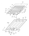
- a touch panel 1 shown in FIG. 1 includes a cover member 3 and a film sensor 5 attached to the back side of the cover member 3.
- the material of the cover member 3 is highly transparent and must not be damaged by an applied impact, and examples thereof include a glass plate and a resin plate.
- a glass plate chemically tempered glass is preferable, and as the material of the resin plate, acrylic resin, polycarbonate resin and the like are preferable.
- a first optical transparent adhesive (OCA) 7 is used for the attachment of the film sensor 5 to the cover member 3 as described above.
- OCA optical transparent adhesive
- an optical transparent adhesive material 7 is provided on at least the back surface of the cover member 3.
- the optical transparent adhesive material 7 include an acrylic type and a rubber type, and an acrylic type is preferable in terms of transparency.
- the film sensor 5 includes, as a basic structure, a first substrate film 11 (an example of a substrate), a second substrate film 13, a plurality of first transparent electrodes 15 (an example of a first detection electrode), and a plurality of It has a second transparent electrode 17 (an example of a second detection electrode), a plurality of first lead wires 19 (an example of a first wire), and a plurality of second lead wires 21 (an example of a second wire).
- the film sensor 5 employs a mutual capacitance method, and the first transparent electrode 15 and the second transparent electrode 17 are band-shaped electrodes arranged in a matrix.
- the first base film 11 and the second base film 13 are arranged side by side in the vertical direction. In this embodiment, the first base film 11 is on the lower side and the second base film 13 is on the upper side.
- the first base film 11 and the second base film 13 are bonded to each other by the second optical transparent adhesive material 9.
- the plurality of first transparent electrodes 15 are arranged side by side on the first base film 11.
- the plurality of first transparent electrodes 15 are electrodes formed on the first base film 11, extending in the Y direction, and arranged at predetermined intervals in the X direction.
- the plurality of second transparent electrodes 17 are formed on the second base film 13.
- the plurality of second transparent electrodes 17 are formed so as to intersect (preferably orthogonally cross) the plurality of first transparent electrodes 15.
- the second transparent electrode 17 is an electrode extending in the X direction and arranged at a predetermined interval in the Y direction.
- the 1st transparent electrode 15 and the 2nd transparent electrode 17 are not limited to a linear shape, For example, even if it is a wave shape, the thing from which thickness changes in the middle may be sufficient.
- the 1st transparent electrode 15 and the 2nd transparent electrode 17 comprise the part (sensing part) which functions as a sensing electrode which senses the change of an electrostatic capacitance in the touch panel 1. That is, when the fingertip is brought into contact with the touch panel 1, the mutual capacitance between the first transparent electrode 15 and the second transparent electrode 17 changes, and the position of the fingertip is detected by a detection control unit (not shown) based on the amount of change. Operate by circuit.
- three first transparent electrodes 15 and six second transparent electrodes 17 are provided, but the number thereof is not particularly limited and may be plural.
- the plurality of first lead wires 19 are formed on the first base film 11.
- the plurality of first lead wires 19 are connected to the plurality of first transparent electrodes 15.
- the plurality of first lead wirings 19 extend in the non-display area of the outer frame on the first base film 11.
- the plurality of first lead wires 19 extend to the connection terminal 25.
- the first lead wiring 19 extends from one end of the first transparent electrode 15 in the Y direction to the edge of the first base film 11 and has a relatively short length.
- the connection terminal 25 is arranged to be shifted to one side in the X direction
- the first lead wiring 19 extending from the farthest side in the X direction with respect to the connection terminal 25 is compared.
- the first portion 19a extends in the X direction for a long time
- the second portion 19b extends in the Y direction therefrom.
- the plurality of second lead wirings 21 are formed on the second base film 13.
- the plurality of second lead wires 21 are connected to the second transparent electrode 17, respectively.
- the plurality of second lead wires 21 extend to the connection terminal 27.
- the second lead wiring 21 is alternately drawn from both ends of the second transparent electrode 17 in the X direction, further extends in the Y direction, and extends to the edge of the first base film 11. The length is relatively long.
- the connection terminal 25 and the connection terminal 27 are arrange
- a flexible printed wiring board (not shown) is connected to the connection terminal 25 and the connection terminal 27, and is electrically connected to a detection circuit of a detection control unit (not shown).
- the first transparent electrode 15 and the second transparent electrode 17 are arranged so as to form a lattice in plan view.
- the first transparent electrode 15 functions as a transmission-side electrode
- the second transparent electrode 17 functions as a reception-side electrode. If the user's finger or the like is not touching or approaching the cover member 3 that covers the film sensor 5, an electric field is formed so that the lines of electric force are directed from the first transparent electrode 15 on the transmission side to the second transparent electrode 17. Has been. When the user's finger or the like touches or approaches the cover through the cover member 3 that covers the film sensor 5, a part of the electric lines of force wrap around the second transparent electrode 17 and is absorbed by the finger or the like.
- the detection circuit of the detection control unit detects the amount of change in electrostatic capacitance that occurs in such a case, and can acquire where in the fluoroscopic region is touched as a set of X coordinate values and Y coordinate values as specific values. It becomes possible.
- first base film 11 and the second base film 13 transparent polyester (PET), polyimide (PI), polyether sulfone (PES), polyether ether ketone (PEEK), polycarbonate ( PC), polypropylene (PP), polyamide (PA), polyacryl (PAC), norbornene-based thermoplastic transparent resin film, or a laminate thereof. Cycloolefin polymers (COP) can also be used.
- the thickness of the first base film 11 and the second base film 13 is usually 20 ⁇ m or more by the individual thickness of each film, and the total thickness of each film used for the film sensor 5 is 500 ⁇ m or less. If the single thickness is less than 20 ⁇ m, handling during film production is difficult, and if the total thickness exceeds 500 ⁇ m, the translucency is lowered.
- the material of the first transparent electrode 15 and the second transparent electrode 17 preferably exhibits a light transmittance (translucency) of 80% or more and a surface resistance value (conductivity) of several m ⁇ to several hundred ⁇ .
- the film can be formed using metal oxides such as indium oxide, tin oxide, indium tin oxide (ITO), and tin antimonic acid, and metals such as gold, silver, copper, platinum, palladium, aluminum, and rhodium.
- a transparent conductive film is formed by a PVD method such as a sputtering method, a vacuum deposition method, or an ion plating method, or a CVD method or a coating method.
- a method of patterning by etching after forming, a printing method, and the like are examples of a PVD method such as a sputtering method, a vacuum deposition method, or an ion plating method, or a CVD method or a coating method.
- the first lead wire 19 and the second lead wire 21 are usually formed by screen printing, but the forming method is not particularly limited. Generally, silver paste, copper paste, silver and carbon, or the like is used as a material for the first lead wiring 19 and the second lead wiring 21, but other materials can be used as long as the volume resistance is kept constant and stable. Material may be selected.
- the first lead wiring 19 and the second lead wiring 21 are composed of a transparent conductive layer made of the same material as the first transparent electrode 15 and the second transparent electrode 17 and a metal layer laminated on the transparent conductive layer. It may be composed of a layer structure. Examples of the material for the metal layer include aluminum, nickel, copper, silver, and tin.
- a transparent conductive film and a metal film are laminated by a PVD method such as a sputtering method, a vacuum deposition method, an ion plating method, or a CVD method or a coating method. Then, there is a method of patterning by etching.
- the touch panel 1 further includes a first shield layer 31A and a second shield layer 31B as an example of a shield layer.
- the first shield layer 31 ⁇ / b> A and the second shield layer 31 ⁇ / b> B are formed on the first base film 11.
- the first shield layer 31 ⁇ / b> A and the second shield layer 31 ⁇ / b> B are disposed so as to overlap the plurality of second lead wires 21 in a plan view.
- the first shield layer 31A and the second shield layer 31B overlap with the plurality of second lead wires 21 in a plan view means a state in which at least a part of both overlap each other. In this embodiment, the first shield layer 31A and the second shield layer 31B overlap each other.
- the layer 31A and the second shield layer 31B cover the plurality of second lead wirings 21 almost entirely.
- One end of each of the first shield layer 31A and the second shield layer 31B is connected to the ground line.
- a transparent conductive film made of the same material as that of the first transparent electrode 15 may be formed on the entire surface or in a mesh shape.
- the first shield layer 31A has a first corner (lower right in FIG. 2), a second corner (upper right in FIG. 3), a third corner (upper left in FIG. 2), and a fourth corner ( 2 (lower left in FIG. 2), and one end near the first corner is connected to the ground line.
- the second shield layer 31B extends in the X direction from the vicinity of the tip of the first shield layer 31A (that is, the vicinity of the fourth corner of the first base film 11). Therefore, the second shield layer 31B is close to the first portion 19a and the second portion 19b of the first lead wiring 19 on the leftmost side of the drawing.
- a gap 31C is secured between the second shield layer 31B and the first shield layer 31A, that is, both are insulated.
- the first shield layer 31A and the second shield layer 31B satisfy the following length condition.
- the length range is set so as not to include the length.
- An example of a target frequency band is 100 MHz to 400 MHz in the TEM cell method.
- the TEM cell test is one of in-vehicle electronic device tests, and is an immunity test for radio waves such as radio / TV broadcast, transceiver, and amateur radio. In the TEM cell test, an expected radio wave is radiated in the TEM cell to check whether the vehicle-mounted product is affected.
- the shield layer preferably avoids a length range of 187.5 mm to 750 mm.
- the first shield layer 31A is preferably more than 750 mm, and the second shield layer 31B is preferably less than 187.5 mm.
- the magnetic permeability increases as the length of the shield layer becomes shorter. Therefore, the second shield layer 31B is preferably less than 100 mm.
- the first shield layer 31A and the second shield layer 31B are unlikely to resonate with electromagnetic waves. Therefore, noise is unlikely to occur in the plurality of first lead wires 19.
- the above-mentioned frequency and the length of a shield layer are illustrations, and this invention is not limited to such embodiment.
- the touch panel 1 further includes a third shield layer 33.
- the third shield layer 33 is formed on the second base film 13.
- the third shield layer 33 is disposed so as to overlap the plurality of first lead wires 19 in plan view.
- the third shield layer 33 overlapping the plurality of first lead wires 19 in a plan view means a state in which at least a part of both overlaps.
- the third shield layer 33 includes a plurality of first lead wires 19.
- One lead-out wiring 19 is covered almost entirely.
- the third shield layer 33 is a small region formed only on a part of one side in the Y direction from the sensing unit.
- the third shield layer 33 is connected to the ground line.
- the third shield layer 33 may be formed by forming a transparent conductive film made of the same material as the second transparent electrode 17 entirely or in a mesh shape.
- the first shield layer 31 ⁇ / b> A and the second shield layer 31 ⁇ / b> B are disposed on the peripheral edge of the first base film 11 so as to surround the first transparent electrode 15 and the plurality of first lead wires 19. .
- the shield layer does not satisfy the above length condition, noise may occur in the first lead-out wiring 19 due to resonance in the shield layer, and the cause is a portion corresponding to the second shield layer 31B. It is estimated that the distance between the first portion 19a and the second portion 19b of the first lead wiring 19 is short and the facing length is long. Therefore, in this touch panel 1, by setting the lengths of the first shield layer 31A and the second shield layer 31B so as to satisfy the above-described conditions, resonance of the shield layer that has conventionally occurred can be prevented. Yes.
- the 1st shield layer 31A and the 2nd shield layer 31B were formed in the 1st base film 11, this invention is not limited to such embodiment. There may be one or three or more shield layers. In the said embodiment, 31 A of 1st shield layers and the 2nd shield layer 31B were cut
- first shield layer 31A and the second shield layer 31B are separated by cutting, the present invention is not limited to such an embodiment.
- the first shield layer 31A and the second shield layer 31B may be patterned so as not to be coupled to each other, for example, by screen printing.
- first shield layer 31A and the second shield layer 31B are formed on the first base film, they may be formed on the second base film.
- the touch panel employs a mutual capacitance method, but the present invention is not limited to such an embodiment.
- the touch panel may adopt a self-capacitance method provided so as to spread rhombus transparent electrodes.
- the connection terminal 25 is displaced from one side in the X direction.
- the connection terminal 25 may be disposed in the center portion in the X direction.
- the two types of transparent electrodes were each provided in the layer of the same side of a 1st base film and a 2nd base film, this invention is not limited to such embodiment.
- the two types of transparent electrodes may be provided on opposite surfaces of the first base film and the second base film, respectively.
- two types of transparent electrodes were each provided in the base material film of 2 sheets, this invention is not limited to such embodiment.
- two types of transparent electrodes may be provided on one side or both sides of one base film.
- the first base film and the second base film are directly bonded, but the present invention is not limited to such an embodiment.
- one layer or a plurality of substrate films may be arranged between the first substrate film and the second substrate film.
- the present invention can be widely applied to touch panels.
- Touch panel 5 Film sensor 11: 1st base film 13: 2nd base film 15: 1st transparent electrode 17: 2nd transparent electrode 19: 1st extraction wiring 21: 2nd extraction wiring 31A: 1st shield Layer 31B: Second shield layer
Landscapes
- Engineering & Computer Science (AREA)
- Physics & Mathematics (AREA)
- Theoretical Computer Science (AREA)
- General Engineering & Computer Science (AREA)
- General Physics & Mathematics (AREA)
- Human Computer Interaction (AREA)
- Nonlinear Science (AREA)
- Optics & Photonics (AREA)
- Crystallography & Structural Chemistry (AREA)
- Chemical & Material Sciences (AREA)
- Mathematical Physics (AREA)
- Electromagnetism (AREA)
- Microelectronics & Electronic Packaging (AREA)
- Position Input By Displaying (AREA)
- Shielding Devices Or Components To Electric Or Magnetic Fields (AREA)
Abstract
Description
そこで、本発明の発明者は、上記現象の原因を追求すると共に、その解決手段を新たに考案した。
複数の第1検出電極は、基材上に形成され、一方向に延びている。
複数の第1配線は、基材上に形成され、複数の第1検出電極に接続されている。
複数の第2検出電極は、複数の第1検出電極に交差するように形成されている。
複数の第2配線は、複数の第2検出電極に接続されている。
シールド層は、基材上に形成され、平面視で複数の第2配線に重なるように配置されている。シールド層は、特定範囲内の複数の周波数に対して共振現象を生じさせないために、各周波数のλ/n(n=2,4,6,・・・)となる長さを含まないように長さ範囲が設定されている。なお、シールド層が平面視で複数の第2配線に重なるとは、少なくとも両者の一部同士が重なっている状態をいう。
このタッチパネルでは、シールド層の長さが上記の条件を満たしているので、シールド層が電磁波に対して共振しにくい。したがって、第1配線にノイズが発生しにくい。
このタッチパネルでは、第1シールド層と第2シールド層を作成する際に、例えばスクリーン印刷によって全体を一度に形成した後に、両者を分断することで第1シールド層と第2シールド層とを得ることができる。
シールド層は第1検出電極及び第1配線を囲うように配置されている場合、従来であれば、シールド層での共振によって第1配線にノイズが発生することがあり、その原因はシールド層と第1配線が対向する部分同士の距離が短くかつ対向部分の長さが長かったことだと推定される。そこで、このタッチパネルでは、シールド層の長さが上記の条件を満たすことで、上記の構造を有するタッチパネルにおいて、シールド層が電磁波に対して共振しにくくしている。その結果、第1配線にノイズが発生しにくい。
図1に示すタッチパネル1は、カバー部材3と、カバー部材3の裏面側に貼り付けられたフィルムセンサ5と、を備えている。
第1基材フィルム11と第2基材フィルム13は、上下方向に並んで配置されている。
この実施形態では、第1基材フィルム11が下方であり、第2基材フィルム13が上方である。
複数の第1透明電極15は、第1基材フィルム11上に並設される。複数の第1透明電極15は、第1基材フィルム11に形成され、Y方向に延び、X方向に所定の間隔をあけて配列された電極である。
なお、第1透明電極15及び第2透明電極17は、は直線形状に限定されるものではなく、例えば、波形状であっても、太さが途中で変わるようなものであってもよい。
なお、この実施形態では、第1透明電極15は3つ、第2透明電極17は6つ設けられているが、その数は特に制限されず複数あればよい。
なお、接続端子25及び接続端子27は、第1基材フィルム11及び第2基材フィル13の延出部41にそれぞれ配置されている。接続端子25及び接続端子27には、フレキシブルプリント配線基板(図示せず)が接続されており、図示しない検出制御部の検出回路に電気的に接続されている。
第1シールド層31A及び第2シールド層31Bはそれぞれ、一端がグランド線に接続されている。
第1シールド層31A及び第2シールド層31Bは、第1透明電極15と同様の材料からなる透明導電膜を全面的に又はメッシュ状に形成したものを用いることができる。
第2シールド層31Bは、第1シールド層31Aの先端近傍(つまり、第1基材フィルム11の第4隅の近傍)からX方向に延びている。したがって、第2シールド層31Bは、最も図左側の第1引出し配線19の第1部分19a及び第2部分19bに近接している。第2シールド層31Bと第1シールド層31Aとの間には隙間31Cが確保されており、つまり両者は絶縁されている。
第1シールド層31Aと第2シールド層31Bを作成する際に、例えばスクリーン印刷によって全体を一度に形成した後に、両者を分断することで第1シールド層31A及び第2シールド層31Bとを得ることができる。
第1シールド層31A及び第2シールド層31Bは、特定範囲内の複数の周波数に対して共振現象を生じさせないために、各周波数のλ/n(n=2,4,6,・・・)となる長さを含まないように長さ範囲が設定されている。
c:電波の速度3x10^8m
λ:波長=n×長さ
n=2,4,6,,,
対象となる周波数帯の一例としては、TEMセル法における100MHz~400MHzがある。TEMセル試験は、車載電子機器試験の一つであり、ラジオ/TV放送、トランシーバ、及びアマチュア無線などの無線電波に対するイミュニティ試験である。TEMセル試験では、想定される電波をTEMセル内にて放射し、車載商品が影響を受けないかを確認する。
100MHz~400MHzを上記式に代入して、1/4ラムダ(n=4)の場合、
3x10^8/100x10^6/4=750mm
3x10^8/400x10^6/4=187.5mm
となり、シールド層が187.5mm~750mmの長さ範囲を避けることが好ましいことが分かる。
このタッチパネル1では、第1シールド層31A及び第2シールド層31Bの長さが上記の条件を満たしているので、第1シールド層31A及び第2シールド層31Bが電磁波に対して共振しにくい。したがって、複数の第1引出し配線19にノイズが発生しにくい。
なお、上述の周波数及びシールド層の長さは例示であり、本発明はそのような実施形態に限定されない。
第3シールド層33はグランド線に接続されている。
第3シールド層33は、第2透明電極17同様の材料からなる透明導電膜を全面的に又はメッシュ状に形成したものを用いることができる。
以上、本発明の一実施形態について説明したが、本発明は上記実施形態に限定されるものではなく、発明の要旨を逸脱しない範囲で種々の変更が可能である。特に、本明細書に書かれた複数の実施形態及び変形例は必要に応じて任意に組み合せ可能である。
前記実施形態では第1シールド層31Aと第2シールド層31Bは第1基材フィルム11の第4隅付近で切断されていたが、切断箇所及び切断形状は特に限定されない。
前記第1シールド層31Aと第2シールド層31Bは、第1基材フィルムに形成されていたが、第2基材フィルムに形成されてもよい。
前記実施形態では接続端子25はX方向片側にずれて配置されていたが、接続端子25はX方向中央部分に配置されていてもよい。
前記実施形態では、2種類の透明電極はそれぞれ2枚の基材フィルムに設けられていたが、本発明はそのような実施形態に限定されない。例えば、2種類の透明電極は1枚の基材フィルムの片面又は両面に設けられていてもよい。
5 :フィルムセンサ
11 :第1基材フィルム
13 :第2基材フィルム
15 :第1透明電極
17 :第2透明電極
19 :第1引出し配線
21 :第2引出し配線
31A :第1シールド層
31B :第2シールド層
Claims (3)
- 基材と、
前記基材上に形成され、一方向に延びる複数の第1検出電極と、
前記基材上に形成され、前記複数の第1検出電極に接続された複数の第1配線と、
前記複数の第1検出電極に交差するように形成された複数の第2検出電極と、
前記複数の第2検出電極に接続された複数の第2配線と、
前記基材上に形成され、平面視で前記複数の第2配線に重なるように配置され、特定範囲内の複数の周波数に対して共振現象を生じさせないために、各周波数のλ/n(n=2,4,6,・・・)となる長さを含まないように長さ範囲が設定されている、シールド層と、
を備えたタッチパネル。 - 前記シールド層は、第1シールド層と、前記第1シールド層から絶縁された第2シールド層を有しており、
前記第1シールド層及び前記第2シールド層は、各周波数のλ/n(n=2,4,6,・・・)となる長さを含まないように長さ範囲が設定されている、請求項1に記載のタッチパネル。 - 前記シールド層は、前記複数の第1検出電極及び前記複数の第1配線を囲うように前記基材の周縁部に配置されている、請求項1又は請求項2に記載のタッチパネル。
Priority Applications (4)
| Application Number | Priority Date | Filing Date | Title |
|---|---|---|---|
| KR1020177015682A KR102093940B1 (ko) | 2014-12-26 | 2015-11-26 | 터치 패널 |
| EP15872604.2A EP3232302B1 (en) | 2014-12-26 | 2015-11-26 | Touch panel |
| CN201580068509.2A CN107003780B (zh) | 2014-12-26 | 2015-11-26 | 触控面板 |
| US15/537,539 US9996206B2 (en) | 2014-12-26 | 2015-11-26 | Touch panel |
Applications Claiming Priority (2)
| Application Number | Priority Date | Filing Date | Title |
|---|---|---|---|
| JP2014-265914 | 2014-12-26 | ||
| JP2014265914A JP5989757B2 (ja) | 2014-12-26 | 2014-12-26 | タッチパネル |
Publications (1)
| Publication Number | Publication Date |
|---|---|
| WO2016104035A1 true WO2016104035A1 (ja) | 2016-06-30 |
Family
ID=56150067
Family Applications (1)
| Application Number | Title | Priority Date | Filing Date |
|---|---|---|---|
| PCT/JP2015/083182 Ceased WO2016104035A1 (ja) | 2014-12-26 | 2015-11-26 | タッチパネル |
Country Status (6)
| Country | Link |
|---|---|
| US (1) | US9996206B2 (ja) |
| EP (1) | EP3232302B1 (ja) |
| JP (1) | JP5989757B2 (ja) |
| KR (1) | KR102093940B1 (ja) |
| CN (1) | CN107003780B (ja) |
| WO (1) | WO2016104035A1 (ja) |
Families Citing this family (2)
| Publication number | Priority date | Publication date | Assignee | Title |
|---|---|---|---|---|
| KR102843273B1 (ko) * | 2019-12-20 | 2025-08-06 | 삼성디스플레이 주식회사 | 표시 장치 |
| CN112987974B (zh) * | 2021-03-29 | 2025-04-29 | 南京华睿川电子科技有限公司 | 一种抗干扰电容式触摸屏功能片 |
Citations (2)
| Publication number | Priority date | Publication date | Assignee | Title |
|---|---|---|---|---|
| JPS58182744A (ja) * | 1982-04-20 | 1983-10-25 | Fujitsu Ltd | 座標検出装置 |
| WO2013157420A1 (ja) * | 2012-04-18 | 2013-10-24 | コニカミノルタ株式会社 | 透光性導電パターン部材及びこれを用いた透光性電磁遮蔽・アンテナ部材 |
Family Cites Families (12)
| Publication number | Priority date | Publication date | Assignee | Title |
|---|---|---|---|---|
| JP2007335781A (ja) * | 2006-06-19 | 2007-12-27 | Mitsubishi Cable Ind Ltd | 電磁波遮蔽材 |
| KR101306249B1 (ko) * | 2006-06-19 | 2013-09-09 | 미츠비시 덴센 고교 가부시키가이샤 | 전자파 차폐재 및 전자파 흡수체 |
| TW201145132A (en) * | 2010-03-11 | 2011-12-16 | Alps Electric Co Ltd | Translucent inputting device |
| JP5540797B2 (ja) * | 2010-03-19 | 2014-07-02 | ソニー株式会社 | センサ装置および表示装置 |
| US8723053B2 (en) * | 2011-03-09 | 2014-05-13 | Select Fabricators, Inc. | Electromagnetically shielded enclosure with operable interfaces |
| JP5168377B2 (ja) | 2011-03-24 | 2013-03-21 | 大日本印刷株式会社 | タッチパネルセンサおよびタッチパネルセンサの製造方法 |
| US8508956B2 (en) * | 2011-05-05 | 2013-08-13 | Carefusion 303, Inc. | Modular shielded electronics enclosure |
| US9033739B2 (en) * | 2011-09-09 | 2015-05-19 | Apple Inc. | Techniques for shielding connectors that allow for conformal coating against corrosion |
| US20140028619A1 (en) * | 2012-07-30 | 2014-01-30 | Lenovo (Beijing) Co., Ltd. | Touch Sensitive Apparatus, Mobile Terminal And Terminal Device |
| KR20150073350A (ko) * | 2013-12-23 | 2015-07-01 | 에스케이하이닉스 주식회사 | 전자기간섭 차폐층을 갖는 반도체 패키지 및 그 제조방법 |
| GB2521835A (en) * | 2014-01-02 | 2015-07-08 | Nokia Technologies Oy | Electromagnetic shielding |
| JP6688133B2 (ja) * | 2016-03-31 | 2020-04-28 | 三菱重工機械システム株式会社 | 料金収受機、料金収受方法及びプログラム |
-
2014
- 2014-12-26 JP JP2014265914A patent/JP5989757B2/ja active Active
-
2015
- 2015-11-26 WO PCT/JP2015/083182 patent/WO2016104035A1/ja not_active Ceased
- 2015-11-26 CN CN201580068509.2A patent/CN107003780B/zh active Active
- 2015-11-26 KR KR1020177015682A patent/KR102093940B1/ko active Active
- 2015-11-26 US US15/537,539 patent/US9996206B2/en active Active
- 2015-11-26 EP EP15872604.2A patent/EP3232302B1/en active Active
Patent Citations (2)
| Publication number | Priority date | Publication date | Assignee | Title |
|---|---|---|---|---|
| JPS58182744A (ja) * | 1982-04-20 | 1983-10-25 | Fujitsu Ltd | 座標検出装置 |
| WO2013157420A1 (ja) * | 2012-04-18 | 2013-10-24 | コニカミノルタ株式会社 | 透光性導電パターン部材及びこれを用いた透光性電磁遮蔽・アンテナ部材 |
Also Published As
| Publication number | Publication date |
|---|---|
| KR20170098817A (ko) | 2017-08-30 |
| CN107003780A (zh) | 2017-08-01 |
| EP3232302A1 (en) | 2017-10-18 |
| US9996206B2 (en) | 2018-06-12 |
| JP5989757B2 (ja) | 2016-09-07 |
| EP3232302B1 (en) | 2020-01-01 |
| US20170351356A1 (en) | 2017-12-07 |
| JP2016126470A (ja) | 2016-07-11 |
| KR102093940B1 (ko) | 2020-03-26 |
| CN107003780B (zh) | 2019-01-08 |
| EP3232302A4 (en) | 2018-01-24 |
Similar Documents
| Publication | Publication Date | Title |
|---|---|---|
| US9898132B2 (en) | Electrode sheet and touch input device | |
| JP6262703B2 (ja) | スマートフォン | |
| US9122088B2 (en) | Capacitance type touch screen | |
| KR101357586B1 (ko) | 터치 패널 | |
| JP2015079526A (ja) | 静電容量方式タッチパネルおよび静電容量方式タッチパネルにおける金属ジャンパの視認性の減少方法 | |
| CN105718114A (zh) | 智能手机 | |
| US20130154994A1 (en) | Transparent capacitive touch panel with electromagnetic shielding effect | |
| JP5472858B2 (ja) | タッチスイッチ | |
| JP5750466B2 (ja) | 静電容量式入力装置 | |
| JP5989757B2 (ja) | タッチパネル | |
| KR20130116854A (ko) | 터치윈도우 | |
| US9342171B2 (en) | Touch panel with first and second electrodes extending in the same direction but on opposite surfaces of a substrate | |
| JP6134965B2 (ja) | タッチパネル装置 | |
| JP6134968B2 (ja) | 表示装置 | |
| US20150136450A1 (en) | Touch panel and method of manufacturing the same | |
| CN202649985U (zh) | 透明电容触摸板的电磁屏蔽结构 | |
| KR101916306B1 (ko) | 터치 패널 | |
| JP2013148941A (ja) | 静電容量式タッチパネル及びその生産方法 | |
| JP2012226498A (ja) | タッチスイッチ | |
| JP5908637B2 (ja) | 静電容量式入力装置 | |
| KR20120120742A (ko) | 터치윈도우 및 그 제조공정 |
Legal Events
| Date | Code | Title | Description |
|---|---|---|---|
| 121 | Ep: the epo has been informed by wipo that ep was designated in this application |
Ref document number: 15872604 Country of ref document: EP Kind code of ref document: A1 |
|
| ENP | Entry into the national phase |
Ref document number: 20177015682 Country of ref document: KR Kind code of ref document: A |
|
| WWE | Wipo information: entry into national phase |
Ref document number: 15537539 Country of ref document: US |
|
| NENP | Non-entry into the national phase |
Ref country code: DE |
|
| REEP | Request for entry into the european phase |
Ref document number: 2015872604 Country of ref document: EP |