WO2016104153A1 - 車両用シート及びそれに用いる車両用シートの成形方法 - Google Patents
車両用シート及びそれに用いる車両用シートの成形方法 Download PDFInfo
- Publication number
- WO2016104153A1 WO2016104153A1 PCT/JP2015/084561 JP2015084561W WO2016104153A1 WO 2016104153 A1 WO2016104153 A1 WO 2016104153A1 JP 2015084561 W JP2015084561 W JP 2015084561W WO 2016104153 A1 WO2016104153 A1 WO 2016104153A1
- Authority
- WO
- WIPO (PCT)
- Prior art keywords
- seat
- trim cover
- concave shape
- vehicle seat
- pad
- Prior art date
- Legal status (The legal status is an assumption and is not a legal conclusion. Google has not performed a legal analysis and makes no representation as to the accuracy of the status listed.)
- Ceased
Links
Images

Classifications
-
- B—PERFORMING OPERATIONS; TRANSPORTING
- B68—SADDLERY; UPHOLSTERY
- B68G—METHODS, EQUIPMENT, OR MACHINES FOR USE IN UPHOLSTERING; UPHOLSTERY NOT OTHERWISE PROVIDED FOR
- B68G7/00—Making upholstery
- B68G7/05—Covering or enveloping cores of pads
- B68G7/052—Covering or enveloping cores of pads with webs secured to the core, e.g. by stitching
-
- A—HUMAN NECESSITIES
- A47—FURNITURE; DOMESTIC ARTICLES OR APPLIANCES; COFFEE MILLS; SPICE MILLS; SUCTION CLEANERS IN GENERAL
- A47C—CHAIRS; SOFAS; BEDS
- A47C31/00—Details or accessories for chairs, beds, or the like, not provided for in other groups of this subclass, e.g. upholstery fasteners, mattress protectors, stretching devices for mattress nets
- A47C31/02—Upholstery attaching means
-
- B—PERFORMING OPERATIONS; TRANSPORTING
- B60—VEHICLES IN GENERAL
- B60N—SEATS SPECIALLY ADAPTED FOR VEHICLES; VEHICLE PASSENGER ACCOMMODATION NOT OTHERWISE PROVIDED FOR
- B60N2/00—Seats specially adapted for vehicles; Arrangement or mounting of seats in vehicles
- B60N2/58—Seat coverings
- B60N2/5816—Seat coverings attachments thereof
- B60N2/5875—Seat coverings attachments thereof by adhesion, e.g. gluing
-
- B—PERFORMING OPERATIONS; TRANSPORTING
- B60—VEHICLES IN GENERAL
- B60N—SEATS SPECIALLY ADAPTED FOR VEHICLES; VEHICLE PASSENGER ACCOMMODATION NOT OTHERWISE PROVIDED FOR
- B60N2/00—Seats specially adapted for vehicles; Arrangement or mounting of seats in vehicles
- B60N2/58—Seat coverings
- B60N2/5816—Seat coverings attachments thereof
- B60N2/5883—Seat coverings attachments thereof by sewing, stitching or threading
-
- B—PERFORMING OPERATIONS; TRANSPORTING
- B60—VEHICLES IN GENERAL
- B60N—SEATS SPECIALLY ADAPTED FOR VEHICLES; VEHICLE PASSENGER ACCOMMODATION NOT OTHERWISE PROVIDED FOR
- B60N2/00—Seats specially adapted for vehicles; Arrangement or mounting of seats in vehicles
- B60N2/58—Seat coverings
- B60N2/5891—Seat coverings characterised by the manufacturing process; manufacturing seat coverings not otherwise provided for
-
- B—PERFORMING OPERATIONS; TRANSPORTING
- B60—VEHICLES IN GENERAL
- B60N—SEATS SPECIALLY ADAPTED FOR VEHICLES; VEHICLE PASSENGER ACCOMMODATION NOT OTHERWISE PROVIDED FOR
- B60N2/00—Seats specially adapted for vehicles; Arrangement or mounting of seats in vehicles
- B60N2/90—Details or parts not otherwise provided for
-
- B—PERFORMING OPERATIONS; TRANSPORTING
- B60—VEHICLES IN GENERAL
- B60R—VEHICLES, VEHICLE FITTINGS, OR VEHICLE PARTS, NOT OTHERWISE PROVIDED FOR
- B60R22/00—Safety belts or body harnesses in vehicles
- B60R22/18—Anchoring devices
- B60R22/26—Anchoring devices secured to the seat
-
- B—PERFORMING OPERATIONS; TRANSPORTING
- B68—SADDLERY; UPHOLSTERY
- B68G—METHODS, EQUIPMENT, OR MACHINES FOR USE IN UPHOLSTERING; UPHOLSTERY NOT OTHERWISE PROVIDED FOR
- B68G7/00—Making upholstery
- B68G7/05—Covering or enveloping cores of pads
-
- B—PERFORMING OPERATIONS; TRANSPORTING
- B60—VEHICLES IN GENERAL
- B60R—VEHICLES, VEHICLE FITTINGS, OR VEHICLE PARTS, NOT OTHERWISE PROVIDED FOR
- B60R22/00—Safety belts or body harnesses in vehicles
- B60R22/18—Anchoring devices
- B60R2022/1806—Anchoring devices for buckles
Definitions
- the present invention relates to a vehicle seat, and more particularly to a method for forming a vehicle seat.
- Patent Document 1 discloses a seat back cushion body in which a dent is formed on the back side, and a bag-like seat cover is covered, and the dent cover portion on the back side is inserted into a hanging bag sewn on the back side. A vehicle seat retracted into a recess by a wire is disclosed.
- Patent Document 1 has a problem that a process related to hanging is necessary and takes time, and further, a member related to hanging is necessary and costs are increased.
- the present invention has been made in view of these problems, and an object of the present invention is to provide a vehicle seat that eliminates the suspension process and is excellent in cost reduction, and a method for forming a vehicle seat used therefor.
- the present invention includes a plurality of means for solving the above-described problems.
- the concave shape of a vehicle seat having a seat frame, a seat pad that covers the seat frame, and a trim cover that covers the seat pad.
- the seat pad has a seat pad groove, the adhesive sheet is sewn to the back surface of the trim cover with an outer stitch, the trim cover is put on the seat pad, and then the outer stitch is attached to the surface of the trim cover.
- a pressing die is pressed to attach a trim cover to the seat pad groove to form a concave shape.
- the present invention it is possible to provide a vehicle seat that can simplify the molding process and is effective in reducing costs, and a method for molding a vehicle seat used therefor.
- FIG. 1 is an external view of a seat back of a vehicle seat in Embodiment 1.
- FIG. 6 is an external view of a vehicle seat in Embodiment 2.
- FIG. It is an external view of the seat back of the vehicle seat in the past. It is a figure explaining the shaping
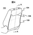
- FIG. 4 is an external view of a conventional seat back of a vehicle seat, and shows a perspective view.
- the seat back 101 is covered with a trim cover 104 in which a sheet-like cover is sewn. Further, in order to form a concave back surface of the seat back, a hook line 108 and a fastener 109 are formed by stitching trim covers.
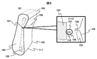
- FIG. 5 is a diagram for explaining a conventional method for forming a vehicle seat.
- the left side view of FIG. 5 shows a cross-sectional view taken along the plane AA of FIG.
- 102 is a seat back frame
- 103 is a seat back pad
- 111 is a trim end fastener
- 107 is a hook ring.
- the right side view of FIG. 5 shows an enlarged view of the periphery of the hook ring 107.
- 105 is a suspending metal width
- 106 is a suspension core wire
- 110 is a suspension wire.
- FIG. 5 right figure As a forming method for making the back surface of the conventional seat back into a concave shape, in FIG. 5 right figure, first, for example, a bag-shaped hanging metal width 105 holding the suspension core wire 106 corresponds to the concave shape portion of the back surface of the seat back. Sewing lines 108 are formed on the back surface of the trim cover 104. Thereafter, the trim cover 104 is covered on the seat back pad 103, the trim end fastener 111 and the fastener 109 are released, the rear surface of the trim cover 104 is rolled up, and the suspension wire 110 and suspension core attached to the seat back frame 102 106 is held by a hook ring 107 and the suspension core wire 106 is suspended.
- the hail line 108 of the trim cover 104 which has been sewn with the hanging metal band 105, is drawn into the seat back frame 102 side to form a concave shape on the trim cover 104. Thereafter, the fastener 109 is closed to complete the molding.
- FIG. 1 is an external view of a seat back of a vehicle seat in the present embodiment, and shows a perspective view.
- a seat back 1 is covered with a trim cover 2 in which a sheet-like cover is sewn.
- an outer stitch 3 is provided to form a concave back surface of the seat back.
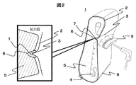
- FIG. 2 is a diagram illustrating a method for forming a vehicle seat in the present embodiment.
- the right side view of FIG. 2 shows a cross-sectional view taken along the plane BB of FIG. 2, 4 is a seat back frame, 5 is a seat back pad, 6 is a seat back pad groove, 7 is an adhesive sheet, and 8 is a trim end fastener.
- the left side view of FIG. 2 shows an enlarged view of the peripheral portion of the seat back pad groove 6.
- the adhesive sheet 7 is sewn to the back of the trim cover 2 with the outer stitch 3 at the deepest part when the concave surface is reproduced.
- the seat back pad 5 is provided with a seat back pad groove 6 in the deepest part when the concave surface is reproduced.
- the trim cover 2 is put on the seat back pad 5, assembled to the seat back frame 4, the trim end fastener 8 is closed, and the seat back pad 5 is covered with the trim cover 2.
- the pressing die 9 is aligned with the outer stitch 3, and the position is inserted into the seat back pad groove 6 and pushed.
- the outer stitch 3 serves as a guide for the position where the pressing die 9 is pushed.
- the rear surface of the trim cover 2 is pulled in a tent shape toward the seat back pad groove 6 to form a concave shape.
- the tip of the pressing die 9 is heated or steam is sprayed from the tip, the adhesive sheet 7 is melted, the trim cover 2 is adhered to the seat back pad groove 6, and the concave shape is formed. To do.
- the trim cover 2 is simply bonded to the seat back pad groove 6 and is not bonded to other seat back pad portions, so that the concave shape can be easily formed and maintained.
- FIG. 2 there is a cavity between the seat back pad 5 and the trim cover 2, but there is no cavity as long as the seat back pad does not interfere with the final concave shape. Also good.
- the adhesive sheet may be simply pushed into the seat back pad groove with the outer die by using a pressing die without melting by heating or steam.
- a hook part for joining the trim cover is provided at the place where the adhesive sheet is to be formed into a concave shape, and the adhesive sheet is used for the sewing allowance of the hook part. May be sewn.
- the corner portion can be used as a guide for the position where the pressing die is pushed.
- the seat back of the vehicle seat has been described. However, it is obvious that even a vehicle seat other than the seat back can be applied when the concave shape is formed.
- the seat back, the seat back frame, the seat back pad, and the seat back pad groove are replaced with the seat, the seat frame, the seat pad, and the seat pad groove, thereby being applied as a concave shape forming method for all vehicle seats. it can.
- the present embodiment is a method for forming a concave shape of a vehicle seat having a seat frame, a seat pad that covers the seat frame, and a trim cover that covers the seat pad, and the seat pad includes a seat pad groove.
- the trim cover is sewed on the back of the trim cover with an outer stitch, and the trim cover is put on the seat pad. To form a concave shape.
- the vehicle seat includes a seat frame, a seat pad that covers the seat frame, and a trim cover that covers the seat pad, the seat pad has a seat pad groove, and the trim cover has an outer stitch or a hook.
- the seam margin of the outer stitch portion or the hook portion is bonded to the seat pad groove to have a concave shape.
- a hanging process is not required, and since the bonding is performed after the trim cover is put on the seat pad, it is not necessary to roll up the trim cover, so that a conventionally required fastener is not necessary. Moreover, the member in connection with suspension becomes unnecessary, and the molding method of the vehicle seat effective for cost reduction and the vehicle seat used therefor can be provided.
- the concave shape of the seat back is formed on the assumption that the rear surface of the front seat back of the vehicle seat has a concave shape in order to secure two spaces for the rear seat occupant has been described. .
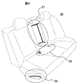
- FIG. 3 is an external view of the vehicle seat in the present embodiment.
- FIG. 3 shows the rear seat 20 of the vehicle seat, and shows the places where the concave surface forming method described in the first embodiment can be applied. That is, in FIG. 3, the armrest storage portion 21 is an enclosed box-shaped concave surface portion, and the method of Example 1 can be applied to the concave surface molding.
- the outer sheet is linearly sewn with the adhesive sheet on the back of the corner that is the stitched portion of the trim cover, and an outer stitch is provided.
- the concave portion can be formed by pressing and adhering the trim cover to the seat pad groove.
- the outer stitch is composed of eight sides (including the hidden portion) indicated by the thick line of the box-shaped concave surface portion, and is constituted by eight line bonds. It should be noted that the line bonding may be performed on only the four sides of the bottom, not focusing on the eight sides.
- the seat belt buckle storage part 22 is provided with an outer stitch by co-sewing an adhesive sheet linearly on the back surface of the corner part that is the stitched part of the trim cover, similar to the armrest storage part, at the time of forming the concave surface part, After the trim cover is put on the seat pad, the pressing die is pressed against the outer stitch, and the trim cover is bonded to the seat pad groove to form the concave surface portion.
- the foot passage space 23 on the seat side surface is a concave surface portion for enabling both the width of the seating surface and the foot passage space when getting on and off, and this concave surface molding is also a concave surface portion, like the armrest storage portion.
- An outer stitch is provided at the corner of the cover, and a trim cover that is sewn together with an adhesive sheet is placed on the seat pad, and then a pressing die is pressed against the outer stitch to attach the trim cover to the seat pad to form a concave portion. I can do it.
- a hook part is provided at the place where the adhesive sheet is placed to form the concave shape, and the trim cover is bonded to the sewing margin of the hook part. You may make it sew a sheet
- the concave portion can be formed by adhering only necessary portions after the trim cover is put on the seat pad. It is possible to provide a vehicle seat that can be simplified and has a small number of parts and is effective for cost reduction, and a method for forming a vehicle seat used therefor.
Landscapes
- Engineering & Computer Science (AREA)
- Mechanical Engineering (AREA)
- Aviation & Aerospace Engineering (AREA)
- Transportation (AREA)
- Manufacturing & Machinery (AREA)
- Textile Engineering (AREA)
- Seats For Vehicles (AREA)
Abstract
車両用シートの凹面形状成形において、吊りによる方法では、吊り工程が必要であり手間が掛かり、さらに、吊りに関わる部材が必要でありコストが掛かるという問題がある。 上記課題を解決するために、シートフレームと、シートフレームを覆うシートパッドと、シートパッドを覆うトリムカバーを有した車両用シートの凹面形状成形方法であって、シートパッドはシートパッド溝を有しており、トリムカバーの裏面に接着用シートをアウターステッチにより縫い付け、トリムカバーをシートパッドに被せた後、アウターステッチにトリムカバーの表面から押し型を押し当ててシートパッド溝にトリムカバーを接着して凹面形状を形成する。これにより、成形工程を簡略化でき、コスト低減に有効な車両用シート及びそれに用いる車両用シートの成形方法を提供することができる。
Description
本発明は、車両用シートに係り、特に車両用シートの成形方法に関する。
車両用シートにおいて、例えば、後席乗員の二―スペースを確保するために、前席シートバックの背面に凹面形状を形成したものが提案されている。このような凹部が形成された車両用シートにおいては、これに被覆されているシートカバーが凹部に弛みなく沿うようにするための成形方法として、例えば、特開平11-342279号公報(特許文献1)がある。特許文献1には、凹みを背裏に形成したシートバック用のクッション体に袋状のシートカバーを被覆してその背裏の凹み被覆部を裏側に縫着された吊り袋に挿通した引込用のワイヤにより凹み内に引き込んだ車両用シートが開示されている。
しかし特許文献1は、吊りに関わる工程が必要であり手間が掛かり、さらに、吊りに関わる部材が必要でありコストが掛かるという問題がある。
本発明はこれらの課題に鑑みなされたものであって、吊り工程が不要になり、コスト低減に優れた車両用シート及びそれに用いる車両用シートの成形方法を提供することを目的とする。
上記課題を解決するために、例えば特許請求の範囲に記載の構成を採用する。本発明は上記課題を解決する手段を複数含んでいるが、その一例を挙げるならば、シートフレームと、シートフレームを覆うシートパッドと、シートパッドを覆うトリムカバーを有した車両用シートの凹面形状成形方法であって、シートパッドはシートパッド溝を有しており、トリムカバーの裏面に接着用シートをアウターステッチにより縫い付け、トリムカバーをシートパッドに被せた後、アウターステッチにトリムカバーの表面から押し型を押し当ててシートパッド溝にトリムカバーを接着して凹面形状を形成する。
本発明によれば、成形工程を簡略化でき、コスト低減に有効な車両用シート及びそれに用いる車両用シートの成形方法を提供することができる。
まず、本発明の前提となる、従来の車両用シートの成形方法例について図面を用いて説明する。
図4は、従来における車両用シートのシートバックの外観図であり、斜視図を示している。図4において、シートバック101は、シート状のカバーが縫製されたトリムカバー104で覆われている。またシートバックの背面を凹面形状するために、トリムカバーを縫い合わせたハギライン108と、ファスナー109を有している。
図5は、従来における車両用シートの成形方法を説明する図である。図5の左側図は、図4のA―A面での断面図を示している。図5左図において、102はシートバックフレーム、103はシートバックパッド、111はトリムエンドファスナー、107はホックリングである。図5の右側図は、ホックリング107の周辺部の拡大図を示している。図5右図において、105は吊り金巾、106は吊芯線、110は吊ワイヤーである。
従来のシートバックの背面を凹面形状とするための成形方法としては、図5右図において、まず、吊芯線106を保持した例えば袋状の吊り金巾105をシートバック背面の凹面形状部分に対応したトリムカバー104の背面に縫製しハギライン108を形成する。その後、トリムカバー104をシートバックパッド103に被覆し、トリムエンドファスナー111、ファスナー109を解放して、トリムカバー104の背面をまくり上げて、シートバックフレーム102に取付けられた吊りワイヤー110と吊芯線106とをホックリング107で保持して吊芯線106を吊り込む。これにより、吊り金巾105が縫製されたトリムカバー104のハギライン108がシートバックフレーム102側に引き込まれてトリムカバー104に凹面形状を形成する。その後、ファスナー109を閉じて成形を完了する。
このように、従来は、トリムカバーをシートバックパッドに被覆した後に、ファスナーを解放してトリムカバーの背面をまくり上げて吊り作業をするという、吊りに関わる工程が必要であり手間が掛かっていた。さらに、吊り金巾、吊芯線、吊ワイヤー、ホックリング等の吊りに関わる部材が必要でありコストが掛かるという問題があった。
よって、これらの課題を解決するための実施例について、下記、図面を用いて説明する。
図1は、本実施例における車両用シートのシートバックの外観図であり、斜視図を示している。図1において、シートバック1は、シート状のカバーが縫製されたトリムカバー2で覆われている。またシートバックの背面を凹面形状するために、アウターステッチ3を有している。
図2は、本実施例における車両用シートの成形方法を説明する図である。図2の右側図は、図1のB―B面での断面図を示している。図2右図において、4はシートバックフレーム、5はシートバックパッド、6はシートバックパッド溝、7は接着用シート、8はトリムエンドファスナーである。図2の左側図は、シートバックパッド溝6の周辺部の拡大図を示している。
本実施例のシートバックの背面を凹面形状とするための成形方法として、図2を用いて説明する。
図2において、トリムカバー2の背面に、凹面再現時に最も深くなる部分に、接着用シート7をアウターステッチ3により縫い付ける。シートバックパッド5には凹面再現時に最も深くなる部分にシートバックパッド溝6を設けておく。
そして、シートバックパッド5にトリムカバー2を被せ、シートバックフレーム4にアセンブリーし、トリムエンドファスナー8を閉じて、シートバックパッド5にトリムカバー2が被覆された状態を作る。
その後、押し型9をアウターステッチ3に合わせ、シートバックパッド溝6に位置を合わせて押し込む。この際、アウターステッチ3は、押し型9を押し込む位置の目安となる。その結果、トリムカバー2の背面はシートバックパッド溝6に向かってテント状に引張られて凹面形状を形成する。その状態のまま押し型9の先端を加熱または先端から蒸気を噴射させ、接着用シート7を溶かし、シートバックパッド溝6にトリムカバー2を接着し凹面形状を維持するようにして凹面形状を形成する。これにより、トリムカバー2は、シートバックパッド溝6と線接着しているだけで、他のシートバックパッド部分とは接着していないので、凹面形状を容易に形成維持できる。なお、図2では、シートバックパッド5とトリムカバー2との間に空洞を有しているが、最終的な凹面形状に対してシートバックパッドが邪魔をしない範囲であれば、空洞は無くてもよい。
また、接着用シートは溶かさなくても接着効果があるものであれば、加熱または蒸気で溶かすことなく、押し型でアウターステッチに合わせシートバックパッド溝に押し込むだけでも良い。
また、上記説明した、接着用シートをアウターステッチにより縫い付ける代わりに、凹面形状とするための接着用シート配置場所に、トリムカバーをはぎ合わせるハギ部を設け、このハギ部の縫い代に接着用シートを縫い付けるようにしても良い。また、その際には、角部にそのハギ部を配置するようにすれば、角部が押し型を押し込む位置の目安とできる。
なお、上記説明では、車両用シートのシートバックについて説明したが、シートバック以外の車両用シートであっても、凹面形状を成形する際に適用できるのは明らかである。すなわち、上記説明において、シートバック、シートバックフレーム、シートバックパッド、シートバックパッド溝を、シート、シートフレーム、シートパッド、シートパッド溝に置き換えることで、車両用シート全般の凹面形状成形方法として適用できる。
以上のように、本実施例は、シートフレームと、シートフレームを覆うシートパッドと、シートパッドを覆うトリムカバーを有した車両用シートの凹面形状成形方法であって、シートパッドはシートパッド溝を有しており、トリムカバーの裏面に接着用シートをアウターステッチにより縫い付け、トリムカバーをシートパッドに被せた後、アウターステッチにトリムカバーの表面から押し型を押し当ててシートパッド溝にトリムカバーを接着して凹面形状を形成するようにした。
また、トリムカバーのハギ部の縫い代に接着用シートを縫い付け、トリムカバーをシートパッドに被せた後、ハギ部にトリムカバーの表面から押し型を押し当ててシートパッド溝にトリムカバーを接着して凹面形状を形成するようにした。
また、車両用シートであって、シートフレームと、シートフレームを覆うシートパッドと、シートパッドを覆うトリムカバーを有し、シートパッドはシートパッド溝を有しており、トリムカバーはアウターステッチまたはハギ部の縫い代を有し、アウターステッチ部分またはハギ部の縫い代部分がシートパッド溝に接着され凹面形状を有した構成とする。
よって、本実施例によれば、吊り工程が不要になり、シートパッドにトリムカバーを被せた後に接着を行う為、トリムカバーをまくり上げる必要が無くなるので、従来必要であったファスナーが必要無くなる。また、吊りに関わる部材が不要となり、コスト低減に有効な車両用シート及びそれに用いる車両用シートの成形方法を提供することができる。
実施例1では、後席乗員の二―スペースを確保するために、車両用シートの前席シートバックの背面に凹面形状を有する場合を想定し、シートバックの凹面形状を形成する場合について説明した。
本実施例では、シートバック以外の凹面形状を形成する場合について説明する。
図3は、本実施例における車両用シートの外観図である。図3は車両用シートの後席20を示しており、実施例1で説明した凹面成形方法を適用できる箇所を示している。すなわち、図3において、アームレスト格納部21は、囲われた箱状の凹面部であり、その凹面成形に実施例1の方法を適用できる。すなわち、凹面成形時には、トリムカバーの縫い合わせ部である角部の裏面に線状に接着用シートを共縫いしアウターステッチを設け、そのトリムカバーをシートパッドに被せたあと、押し型をアウターステッチに押し当ててトリムカバーをシートパッド溝に接着し凹面部を成形することが出来る。この際、アウターステッチは、箱状の凹面部の太線で示した8辺(隠れているところも含めて)からなり、8つの線接着で構成される。なお、8辺にこだわらず、底辺の4辺だけで線接着してもよい。
また、シートベルトバックル格納部22は、その凹面部成形時には、アームレスト格納部と同様に、トリムカバーの縫い合わせ部である角部の裏面に線状に接着用シートを共縫いしアウターステッチを設け、そのトリムカバーをシートパッドに被せたあと、押し型をアウターステッチに押し当ててトリムカバーをシートパッド溝に接着し凹面部を成形することが出来る。
また、シートサイド面の足通過スペース23は、着座面の広さと乗降時の足通過スペースの両立を可能とするための凹面部であり、この凹面成形も、アームレスト格納部と同様に、凹面部の角部にアウターステッチを設け、接着用シートを共縫いしたトリムカバーをシートパッドに被せた後、押し型をアウターステッチに押し当ててトリムカバーをシートパッドに接着し凹面部を成形することが出来る。
なお、本実施例でも、接着用シートをアウターステッチにより縫い付ける代わりに、凹面形状とするための接着用シート配置場所に、トリムカバーをはぎ合わせるハギ部を設け、このハギ部の縫い代に接着用シートを縫い付けるようにしても良い。
このように、本実施例は、シートバック以外の凹面形状の形成においても、トリムカバーをシートパッドに被せた後から必要な部分だけを接着し凹面部を成形することが出来るので、成形工程が簡略化でき、かつ、部品点数が少なくコスト低減に有効な車両用シート及びそれに用いる車両用シートの成形方法を提供することができる。
なお、本実施例は、後席について説明したが、他の座席でも同様の効果が得られる。
以上実施例について説明したが、本発明は上記した実施例に限定されるものではなく、様々な変形例が含まれる。また、上記した実施例は本発明を分かりやすく説明するために詳細に説明したものであり、必ずしも説明した全ての構成を備えるものに限定されるものではない。また、実施例の構成の一部を他の構成に置き換えることも可能である。
1、101…シートバック、2、104…トリムカバー、3…アウターステッチ、
4、102…シートバックフレーム、5、103…シートバックパッド、
6…シートバックパッド溝、7…接着用シート、8、111…トリムエンドファスナー、
9…押し型、20…車両用シートの後席、21…アームレスト格納部、
22…シートベルトバックル格納部、23…シートサイド面の足通過スペース、
105…吊り金巾、106…吊芯線、107…ホックリング、108…ハギライン、
109…ファスナー、110…吊ワイヤー、
4、102…シートバックフレーム、5、103…シートバックパッド、
6…シートバックパッド溝、7…接着用シート、8、111…トリムエンドファスナー、
9…押し型、20…車両用シートの後席、21…アームレスト格納部、
22…シートベルトバックル格納部、23…シートサイド面の足通過スペース、
105…吊り金巾、106…吊芯線、107…ホックリング、108…ハギライン、
109…ファスナー、110…吊ワイヤー、
Claims (13)
- シートフレームと、該シートフレームを覆うシートパッドと、該シートパッドを覆うトリムカバーを有した車両用シートの凹面形状成形方法であって、
前記シートパッドはシートパッド溝を有しており、
前記トリムカバーの裏面に接着用シートをアウターステッチにより縫い付け、
該トリムカバーを前記シートパッドに被せた後、
前記アウターステッチに前記トリムカバーの表面から押し型を押し当てて前記シートパッド溝に前記トリムカバーを接着して凹面形状を形成することを特徴とする車両用シートの凹面形状成形方法。 - シートフレームと、該シートフレームを覆うシートパッドと、該シートパッドを覆うトリムカバーを有した車両用シートの凹面形状成形方法であって、
前記シートパッドはシートパッド溝を有しており、
前記トリムカバーのハギ部の縫い代に接着用シートを縫い付け、
該トリムカバーを前記シートパッドに被せた後、
前記ハギ部に前記トリムカバーの表面から押し型を押し当てて前記シートパッド溝に前記トリムカバーを接着して凹面形状を形成することを特徴とする車両用シートの凹面形状成形方法。 - 請求項1に記載の車両用シートの凹面形状成形方法であって、
前記押し型の先端の加熱または先端より蒸気を噴射させ、前記接着用シートを溶かし、前記シートパッド溝に前記トリムカバーを接着して凹面形状を形成することを特徴とする車両用シートの凹面形状成形方法。 - 請求項2に記載の車両用シートの凹面形状成形方法であって、
前記押し型の先端の加熱または先端より蒸気を噴射させ、前記接着用シートを溶かし、前記シートパッド溝に前記トリムカバーを接着して凹面形状を形成することを特徴とする車両用シートの凹面形状成形方法。 - 請求項1に記載の車両用シートの凹面形状成形方法であって、
前記トリムカバーは前記シートパッド溝に線接着して凹面形状を形成することを特徴とする車両用シートの凹面形状成形方法。 - 請求項2に記載の車両用シートの凹面形状成形方法であって、
前記トリムカバーは前記シートパッド溝に線接着して凹面形状を形成することを特徴とする車両用シートの凹面形状成形方法。 - シートフレームと、
前記シートフレームを覆うシートパッドと、
前記シートパッドを覆うトリムカバーを有し、
前記シートパッドはシートパッド溝を有しており、
前記トリムカバーはアウターステッチまたはハギ部の縫い代を有し、該アウターステッチまたはハギ部の縫い代部分が前記シートパッド溝に接着され凹面形状を有していることを特徴とする車両用シート。 - 請求項7に記載の車両用シートであって、
前記トリムカバーは前記シートパッド溝に線接着され凹面形状を有していることを特徴とする車両用シート。 - 請求項8に記載の車両用シートであって、
前記線接着を複数本設けたことを特徴とする車両用シート。 - 請求項7に記載の車両用シートであって、
前記車両用シートは、シートバックであり、
前記シートフレームはシートバックフレームであり、
前記シートパッドはシートバックパッドであり、
前記シートパッド溝はシートバックパッド溝である
ことを特徴とする車両用シート。 - 請求項7に記載の車両用シートであって、
前記凹面形状は、アームレスト格納部であることを特徴とする車両用シート。 - 請求項7に記載の車両用シートであって、
前記凹面形状は、シートベルトバックル格納部であることを特徴とする車両用シート。 - 請求項7に記載の車両用シートであって、
前記凹面形状は、シートサイド面の足通過スペースであることを特徴とする車両用シート。
Priority Applications (3)
| Application Number | Priority Date | Filing Date | Title |
|---|---|---|---|
| EP15872722.2A EP3239095A4 (en) | 2014-12-25 | 2015-12-09 | Vehicle seat and vehicle seat molding method used for same |
| CN201580068709.8A CN107001024B (zh) | 2014-12-25 | 2015-12-09 | 车辆用座椅以及其所使用的车辆用座椅的成形方法 |
| US15/539,592 US10351415B2 (en) | 2014-12-25 | 2015-12-09 | Vehicle seat and vehicle seat molding method used for same |
Applications Claiming Priority (2)
| Application Number | Priority Date | Filing Date | Title |
|---|---|---|---|
| JP2014-262260 | 2014-12-25 | ||
| JP2014262260A JP6502664B2 (ja) | 2014-12-25 | 2014-12-25 | 車両用シート及びそれに用いる車両用シートの成形方法 |
Publications (1)
| Publication Number | Publication Date |
|---|---|
| WO2016104153A1 true WO2016104153A1 (ja) | 2016-06-30 |
Family
ID=56150183
Family Applications (1)
| Application Number | Title | Priority Date | Filing Date |
|---|---|---|---|
| PCT/JP2015/084561 Ceased WO2016104153A1 (ja) | 2014-12-25 | 2015-12-09 | 車両用シート及びそれに用いる車両用シートの成形方法 |
Country Status (5)
| Country | Link |
|---|---|
| US (1) | US10351415B2 (ja) |
| EP (1) | EP3239095A4 (ja) |
| JP (1) | JP6502664B2 (ja) |
| CN (1) | CN107001024B (ja) |
| WO (1) | WO2016104153A1 (ja) |
Families Citing this family (4)
| Publication number | Priority date | Publication date | Assignee | Title |
|---|---|---|---|---|
| JP6552826B2 (ja) * | 2015-01-15 | 2019-07-31 | 株式会社タチエス | 車両用シート及びその製造方法 |
| JP6964943B2 (ja) * | 2017-10-12 | 2021-11-10 | 株式会社タチエス | 車両用シート |
| CN114929516B (zh) * | 2020-01-10 | 2024-01-26 | 麦格纳座椅公司 | 具有多个缝合对准特征部的模制面板组件 |
| KR102367079B1 (ko) * | 2021-10-22 | 2022-02-25 | 주식회사 한울시스템 | 차량 시트용 스팀다림시스템 |
Citations (2)
| Publication number | Priority date | Publication date | Assignee | Title |
|---|---|---|---|---|
| JPS6270900U (ja) * | 1985-10-25 | 1987-05-06 | ||
| JPH02200296A (ja) * | 1989-01-31 | 1990-08-08 | Tachi S Co Ltd | シートの組立方法 |
Family Cites Families (16)
| Publication number | Priority date | Publication date | Assignee | Title |
|---|---|---|---|---|
| US3794378A (en) * | 1972-11-24 | 1974-02-26 | Ford Motor Co | Seat assembly |
| GB2199492B (en) * | 1987-01-16 | 1990-02-14 | Tachi S Co | Vehicle seat |
| JPH0420319Y2 (ja) * | 1987-06-06 | 1992-05-08 | ||
| US5016941A (en) * | 1990-03-13 | 1991-05-21 | Tachi-S Co. Ltd. | Structure of vehicle seat |
| FR2674485B1 (fr) * | 1991-03-28 | 1993-07-09 | Faure Bertrand Automobile | Perfectionnements aux dossiers de sieges de vehicules. |
| US5248356A (en) * | 1992-09-17 | 1993-09-28 | Tachi-S Co. Ltd. | Method of covering an automotive seat having a seat belt through-bore |
| JPH0724159A (ja) | 1993-05-10 | 1995-01-27 | Nhk Spring Co Ltd | シートおよびその製造方法 |
| JPH1052580A (ja) * | 1996-08-12 | 1998-02-24 | Tachi S Co Ltd | シートのトリムカバー接着型構造 |
| DE19743082B4 (de) * | 1997-09-30 | 2006-12-14 | Bayerische Motoren Werke Ag | Aus wenigstens zwei Bezugsteilen bestehender Sitzbezug und dessen Befestigung auf der Polsterauflage eines Sitzes |
| US6073996A (en) * | 1997-12-31 | 2000-06-13 | Tachi-S Co., Ltd. | Structure of seat back with armrest and method for forming the same |
| JPH11342279A (ja) | 1998-06-03 | 1999-12-14 | Takashimaya Nippatsu Kogyo Co Ltd | 車両用シート |
| CN1154558C (zh) * | 2001-12-28 | 2004-06-23 | 张炳淳 | 将紧固件嵌入到座垫中的方法 |
| JP2005058549A (ja) * | 2003-08-18 | 2005-03-10 | Tachi S Co Ltd | 接着シートとその接着方法 |
| US7073693B2 (en) * | 2003-10-16 | 2006-07-11 | Intier Automotive Inc. | Drawstringing kit |
| JP2008264040A (ja) * | 2007-04-17 | 2008-11-06 | Nissan Motor Co Ltd | シート |
| CN203511362U (zh) * | 2013-10-15 | 2014-04-02 | 廊坊市金色时光科技发展有限公司 | 一种座椅按摩垫体固定结构 |
-
2014
- 2014-12-25 JP JP2014262260A patent/JP6502664B2/ja active Active
-
2015
- 2015-12-09 CN CN201580068709.8A patent/CN107001024B/zh not_active Expired - Fee Related
- 2015-12-09 EP EP15872722.2A patent/EP3239095A4/en not_active Withdrawn
- 2015-12-09 US US15/539,592 patent/US10351415B2/en active Active
- 2015-12-09 WO PCT/JP2015/084561 patent/WO2016104153A1/ja not_active Ceased
Patent Citations (2)
| Publication number | Priority date | Publication date | Assignee | Title |
|---|---|---|---|---|
| JPS6270900U (ja) * | 1985-10-25 | 1987-05-06 | ||
| JPH02200296A (ja) * | 1989-01-31 | 1990-08-08 | Tachi S Co Ltd | シートの組立方法 |
Non-Patent Citations (1)
| Title |
|---|
| See also references of EP3239095A4 * |
Also Published As
| Publication number | Publication date |
|---|---|
| EP3239095A1 (en) | 2017-11-01 |
| EP3239095A4 (en) | 2018-07-25 |
| JP6502664B2 (ja) | 2019-04-17 |
| JP2016120087A (ja) | 2016-07-07 |
| US20170349429A1 (en) | 2017-12-07 |
| CN107001024A (zh) | 2017-08-01 |
| US10351415B2 (en) | 2019-07-16 |
| CN107001024B (zh) | 2019-10-01 |
Similar Documents
| Publication | Publication Date | Title |
|---|---|---|
| KR101579064B1 (ko) | 스티칭 대신에 필름 접착제를 사용하는 차량 내장 처리 | |
| JP6278566B2 (ja) | ワディング材付シートの表皮構造およびワディング材付シートの表皮製造方法 | |
| CN105392667B (zh) | 座垫 | |
| WO2016104153A1 (ja) | 車両用シート及びそれに用いる車両用シートの成形方法 | |
| CN107107800B (zh) | 车辆用座椅及车辆用座椅的制造方法 | |
| JP2009090089A (ja) | クッションパッド | |
| US10251491B2 (en) | Seat | |
| JP6322296B2 (ja) | シート | |
| US10369910B1 (en) | Aesthetic seat backrest panel for a motor vehicle | |
| JP6704707B2 (ja) | 車両用シートのトリムカバーの縫製処理方法、及びそれを用いた車両用シート | |
| CN109153344B (zh) | 边缘条、座椅盖及包括座椅盖的座椅 | |
| JP7013328B2 (ja) | シート | |
| JP6689055B2 (ja) | 座席装置 | |
| JP2019018744A (ja) | 乗物用シートの製造方法、及び乗物用シート | |
| JPH02200296A (ja) | シートの組立方法 | |
| JP6629578B2 (ja) | 乗物用シート及びその製造方法 | |
| US1497247A (en) | Perambulator and other vehicle | |
| JP2012232701A (ja) | 車両用シート | |
| JPS59214484A (ja) | 座席クツシヨン体の一体成形法 | |
| JP2006116060A (ja) | 自動車シートに用いる表皮 | |
| JP4767045B2 (ja) | 車両用表層材の接合部材 | |
| JP2016101324A (ja) | 車両用シート及びその製造方法 | |
| JP7096474B2 (ja) | 乗物用シート | |
| JP2015002762A (ja) | 車両用の表皮一体発泡品とその製造方法 | |
| JPH0335198Y2 (ja) |
Legal Events
| Date | Code | Title | Description |
|---|---|---|---|
| 121 | Ep: the epo has been informed by wipo that ep was designated in this application |
Ref document number: 15872722 Country of ref document: EP Kind code of ref document: A1 |
|
| REEP | Request for entry into the european phase |
Ref document number: 2015872722 Country of ref document: EP |
|
| WWE | Wipo information: entry into national phase |
Ref document number: 15539592 Country of ref document: US |
|
| NENP | Non-entry into the national phase |
Ref country code: DE |