WO2016104166A1 - 撮像システム - Google Patents
撮像システム Download PDFInfo
- Publication number
- WO2016104166A1 WO2016104166A1 PCT/JP2015/084649 JP2015084649W WO2016104166A1 WO 2016104166 A1 WO2016104166 A1 WO 2016104166A1 JP 2015084649 W JP2015084649 W JP 2015084649W WO 2016104166 A1 WO2016104166 A1 WO 2016104166A1
- Authority
- WO
- WIPO (PCT)
- Prior art keywords
- white balance
- balance value
- vehicle
- unit
- imaging
- Prior art date
- Legal status (The legal status is an assumption and is not a legal conclusion. Google has not performed a legal analysis and makes no representation as to the accuracy of the status listed.)
- Ceased
Links
Images







Classifications
-
- H—ELECTRICITY
- H04—ELECTRIC COMMUNICATION TECHNIQUE
- H04N—PICTORIAL COMMUNICATION, e.g. TELEVISION
- H04N5/00—Details of television systems
- H04N5/222—Studio circuitry; Studio devices; Studio equipment
- H04N5/262—Studio circuits, e.g. for mixing, switching-over, change of character of image, other special effects ; Cameras specially adapted for the electronic generation of special effects
- H04N5/265—Mixing
-
- H—ELECTRICITY
- H04—ELECTRIC COMMUNICATION TECHNIQUE
- H04N—PICTORIAL COMMUNICATION, e.g. TELEVISION
- H04N7/00—Television systems
- H04N7/18—Closed-circuit television [CCTV] systems, i.e. systems in which the video signal is not broadcast
- H04N7/181—Closed-circuit television [CCTV] systems, i.e. systems in which the video signal is not broadcast for receiving images from a plurality of remote sources
-
- H—ELECTRICITY
- H04—ELECTRIC COMMUNICATION TECHNIQUE
- H04N—PICTORIAL COMMUNICATION, e.g. TELEVISION
- H04N23/00—Cameras or camera modules comprising electronic image sensors; Control thereof
- H04N23/10—Cameras or camera modules comprising electronic image sensors; Control thereof for generating image signals from different wavelengths
-
- H—ELECTRICITY
- H04—ELECTRIC COMMUNICATION TECHNIQUE
- H04N—PICTORIAL COMMUNICATION, e.g. TELEVISION
- H04N23/00—Cameras or camera modules comprising electronic image sensors; Control thereof
- H04N23/60—Control of cameras or camera modules
- H04N23/698—Control of cameras or camera modules for achieving an enlarged field of view, e.g. panoramic image capture
-
- H—ELECTRICITY
- H04—ELECTRIC COMMUNICATION TECHNIQUE
- H04N—PICTORIAL COMMUNICATION, e.g. TELEVISION
- H04N23/00—Cameras or camera modules comprising electronic image sensors; Control thereof
- H04N23/80—Camera processing pipelines; Components thereof
- H04N23/84—Camera processing pipelines; Components thereof for processing colour signals
- H04N23/88—Camera processing pipelines; Components thereof for processing colour signals for colour balance, e.g. white-balance circuits or colour temperature control
-
- H—ELECTRICITY
- H04—ELECTRIC COMMUNICATION TECHNIQUE
- H04N—PICTORIAL COMMUNICATION, e.g. TELEVISION
- H04N23/00—Cameras or camera modules comprising electronic image sensors; Control thereof
- H04N23/90—Arrangement of cameras or camera modules, e.g. multiple cameras in TV studios or sports stadiums
Definitions
- the present disclosure relates to an imaging system that corrects the white balance value of a subject image captured by a plurality of imaging devices.
- Patent Document 1 describes a camera system that adjusts the white balance of a plurality of imaging cameras for television broadcasting.
- white balance information obtained by imaging a white subject in each imaging camera before imaging is averaged.
- the averaged white balance information is transmitted to all the imaging cameras, and each of the imaging cameras adjusts the white balance based on the averaged white balance information.
- the brightness of the subject image captured by each imaging camera may change frequently and severely for each imaging camera.
- An object of the embodiment is to provide an imaging system that can optimally share and correct white balance values of images of a subject captured by a plurality of imaging devices installed in a moving body.
- a plurality of imaging devices that are mounted on the same moving body and capture an image of a subject to acquire an image, and a target white balance value that is common to the images acquired by the imaging devices
- Each of the imaging devices and a white balance calculation unit that calculates an individual white balance value of an image acquired by the imaging device, and an image that is captured by each of the imaging devices based on a target white balance value.
- a white balance correction unit that corrects an individual white balance value of the image of the subject to be a target white balance value, and the control unit is configured to select each imaging device based on a weighting coefficient set for each imaging device.
- a weighting unit that individually weights each individual white balance value given from the above, and an average of the weighted individual white balance values It calculates an imaging system characterized by having an average value calculation unit to the target white balance value the average value of the individual white balance value is provided.
- the imaging system of the embodiment it is possible to optimally share and correct the white balance value of the image of the subject imaged by the plurality of imaging devices installed on the moving body.
- FIG. 1 is a diagram illustrating an example of the overall configuration of the imaging system according to the embodiment.
- FIG. 2 is a diagram illustrating another example of the overall configuration of the imaging system according to the embodiment.
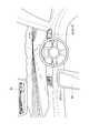
- FIG. 3 is a diagram schematically illustrating a situation around a driver's seat of a vehicle on which an example display device on which an image obtained by the imaging system according to the embodiment is displayed.
- FIG. 4 is a diagram illustrating an example of a display example in which images captured by a plurality of imaging devices are displayed on one display device.
- FIG. 5 is a diagram illustrating an example of an arrangement position of each imaging device mounted on the vehicle.
- FIG. 6 is a diagram illustrating an example of a display example in which images captured by a plurality of imaging devices are combined and displayed on one display device.
- FIG. 7 is a diagram illustrating a configuration of the imaging apparatus.
- FIG. 8 is a diagram illustrating a configuration of the control unit.
- FIG. 9 is a diagram illustrating the classification of the arrangement location set when specifying the arrangement location of the imaging device arranged in the vehicle.
- FIG. 10 is a diagram illustrating an example of specific numerical values of the weighting coefficient of the white balance value of the images captured by the imaging devices installed at the nine installation locations illustrated in FIG.
- FIG. 11 is a diagram illustrating an example of a change in the color temperature imaged by the imaging device using the weighting coefficient as a parameter.
- FIG. 12 is a flowchart illustrating a procedure of operation processing according to the embodiment.
- the imaging system 1 includes a plurality of imaging devices 11 and a control unit 12.
- the imaging system 1 is configured, for example, by connecting four imaging devices 11 to one control unit 12 in common.
- Each imaging device 11 is mounted on the same moving body such as a vehicle, a ship, and a flying body, for example, and images a subject to obtain image data.
- the vehicle described below refers to a vehicle on which the imaging system 1 is mounted.
- control unit 12 is provided separately from the plurality of imaging devices 11, but as shown in FIG. 2, any one of the plurality of imaging devices 11. It may be provided inside and may be integrated with one imaging device 11.
- Necessary information is transmitted between each imaging device 11 and the control unit 12 by wired or wireless communication.
- the imaging system 1 calculates a target white balance value that is common to the imaging apparatuses 11, and corrects the individual white balance value calculated by each imaging apparatus 11 to the target white balance value. Images captured by each imaging device 11 and corrected to the target white balance value can be appropriately combined and displayed on the display device 2 connected to each imaging device 11. That is, when a plurality of images picked up by the respective image pickup devices 11 are displayed on the display device 2, the white balance values of the plurality of displayed images are all unified to the target white balance value.
- FIGS. 1 and 2 Although only one display device 2 is shown in FIGS. 1 and 2, a plurality of display devices 2 may be provided.
- FIG. 3 is a diagram schematically showing the situation around the driver's seat of the vehicle.
- the display device 2 includes, for example, a digital room mirror 31 and a digital side mirror 32 (32-L, 32-R) configured by a liquid crystal display for displaying an image picked up by the image pickup device 11. Composed. Further, the display device 2 includes a navigation display 33 configured by a liquid crystal display that displays map information or the like in the navigation system shown in FIG. 3, for example.
- the display device 2 is arranged adjacent to, for example, a head-up display that displays an image on a windshield or instruments arranged on a dashboard. It consists of a cluster display that displays
- the display device 2 is not limited to the above, and may be a display device having any configuration as long as it can display an image captured by each imaging device 11.
- FIG. 4 is a diagram illustrating an example of an image displayed on the digital room mirror 31.
- an image 41 behind the vehicle is displayed at the center of the digital room mirror 31.
- an image 42 on the left rear side of the vehicle is displayed side by side with the image 41 on the left side of the image 41.
- a right rear image 43 of the vehicle is displayed alongside the image 41 on the right side of the image 41.
- FIG. 5 is a diagram illustrating an example of an installation position of each imaging device 11 in the vehicle 51 when the imaging system 1 includes, for example, four imaging devices 11. Each imaging device 11 is not limited to the installation position shown in FIG.
- the image 41 displayed on the digital room mirror 31 is taken by the imaging device 11-R installed at the rear part of the vehicle 51 shown in FIG.
- the image 42 displayed on the digital room mirror 31 is taken by the imaging device 11-SL installed on the door mirror on the left side of the vehicle 51 shown in FIG.
- the image 43 displayed on the digital room mirror 31 is taken by the imaging device 11-SR installed on the door mirror on the right side of the vehicle 51 shown in FIG.
- the left digital side mirror 32-L displays, for example, an image captured by the imaging device 11-SL
- the right digital side mirror 32-R displays, for example, an image captured by the imaging device 11-SR. Is done.
- FIG. 6 shows an example of an image displayed on the navigation display 33.
- the navigation display 33 displays a bird's-eye view image 61 around the vehicle including the vehicle 51, which is generated by synthesizing images captured by a plurality of imaging devices installed at different positions of the vehicle 51. Yes.
- the overhead view image 61 around the vehicle 51 displayed on the navigation display 33 is configured by combining the overhead view images 62 to 65.
- the overhead image 62 is an overhead image in front of the vehicle 51
- the overhead image 63 is an overhead image on the left side of the vehicle 51
- the overhead image 64 is an overhead image on the right side of the vehicle 51
- the overhead image 65 Is a bird's-eye view image of the rear of the vehicle 51.
- the bird's-eye view image 62 is generated based on, for example, an image captured by the imaging device 11-F installed in the front portion of the vehicle 51 shown in FIG. 5, and the bird's-eye view image 63 is, for example, the imaging device 11-SL shown in FIG. It is generated based on the image picked up by
- the overhead image 64 is generated based on, for example, an image captured by the imaging device 11-SR shown in FIG. 5, and the overhead image 65 is generated based on, for example, an image captured by the imaging device 11-R shown in FIG. Is done.
- Each imaging device 11 is configured as shown in FIG. Since each imaging device 11 has the same configuration in the system configuration shown in FIG. 1, the configuration of the imaging device 11 will be described on behalf of one imaging device 11.
- the imaging device 11 includes an imaging unit 100 that captures an image of a subject and obtains an analog image signal of the subject.
- the imaging unit 100 includes an imaging element 1004 including a zoom lens 1001, a focus lens 1002, a diaphragm 1003, an image sensor, and the like.
- the zoom lens 1001 is moved along the optical axis by a zoom actuator (not shown).
- the focus lens 1002 is moved along the optical axis by a focus actuator (not shown).
- the diaphragm 1003 operates by being driven by a diaphragm actuator (not shown).
- Imaging using the imaging unit 100 is performed according to the following procedure.
- the image sensor 1004 photoelectrically converts light that has passed through the zoom lens 1001, the focus lens 1002, and the stop 1003 to generate an analog image signal of the subject.
- the generated analog image signal is given to the analog image signal processing unit 101.
- the A / D conversion unit 102 converts the amplified signal into digital image data.
- the image input controller 103 captures the digital image data given from the A / D conversion unit 102 and stores the captured digital image data in the RAM 105 connected to the bus 104 via the bus 104.
- a digital signal processing unit 106, a white balance correction unit 107, and an imaging control unit 108 are connected to the bus 104.
- the digital signal processing unit 106 reads the digital image data stored in the RAM 105 via the bus 104 under the control of the imaging control unit 108, performs predetermined signal processing, and outputs data including the luminance signal and the color difference signal. Generate.
- the digital signal processing unit 106 performs various digital correction processes on the digital image data based on sensitivity information at the time of imaging output from the image sensor 1004, for example, AGC gain or ISO sensitivity.
- the various digital correction processes are, for example, an offset process, a gamma correction process, a gain process, an RGB complement process, a noise reduction process, a contour correction process, a color tone correction process, a light source type determination process, and the like.
- AGC is an abbreviation for Automatic Gain Control
- ISO is an abbreviation for International Organization for Standardization.
- the white balance correction unit 107 corrects the individual white balance value calculated by each imaging device 11 to the target white balance value based on the target white balance value and the correction speed calculated by the control unit 12 described later.
- the imaging control unit 108 reads out a control program for controlling the overall operation of the imaging apparatus 11 stored in the ROM 109 via the bus 104, and performs overall control of the overall operation of the imaging apparatus 11 based on the read control program.
- the imaging control unit 108 can be configured by a microcomputer having a CPU.
- the imaging control unit 108 includes an actuator / sensor control unit 1081, a white balance calculation unit 1082, a correction determination unit 1083, an IR sensor signal acquisition unit 1084, and a communication unit 1085.
- the actuator / sensor control unit 1081 controls driving of the zoom actuator, the focus actuator, and the aperture actuator (not shown) of the imaging unit 100 described above.
- the actuator / sensor control unit 1081 controls the photoelectric conversion operation of the image sensor 1004.
- the white balance calculation unit 1082 refers to the digital image data stored in the RAM 105 via the bus 104 and measures the distribution of R (red), G (green), and B (blue) values of the color information of the digital image data.
- the white balance calculation unit 1082 divides the digital image data whose distribution is to be measured into a plurality of regions, obtains an average value of the RGB values for each divided region, and creates a histogram to thereby obtain the RGB values of the digital image data. Measure the distribution of.
- the white balance calculation unit 1082 performs a pattern matching process for comparing the created histogram with a histogram of a white balance calculation table prepared in advance.
- This white balance calculation table is a table showing the correspondence between the histogram representing the distribution of RGB values, the white balance value, and the color temperature of the image, and is stored in advance in a storage device, for example, the ROM 109.
- the white balance calculation unit 1082 calculates, as a result of the pattern matching process, a white balance value that matches or is closest to the created histogram as the white balance value of the digital image data.
- the calculated white balance value is an individual white balance value calculated individually for each imaging device 11.
- the white balance calculation unit 1082 may calculate the color temperature of the digital image data instead of the white balance value, and calculate the white balance value from the color temperature. Further, the white balance calculation unit 1082 may calculate both the white balance value and the color temperature.
- the correspondence relationship between the white balance value and the color temperature depends on characteristics of the lenses (zoom lens 1001, focus lens 1002) of the imaging unit 100, the imaging device 1004, a filter (not shown), and the like. For this reason, the correspondence between the white balance value and the color temperature is unique to each imaging device 11, and is stored in advance in the white balance ROM 110 of each imaging device 11 when each imaging device 11 is produced.
- the white balance calculation unit 1082 calculates only the individual white balance value from the histogram, and calculates the target white balance value by performing various processes described later based on the calculated individual white balance value.
- the correction determination unit 1083 starts and continues the correction processing of the individual white balance value based on the engine start / stop notification given from the ECU (engine control unit) (not shown) via the control unit 12. And end.
- the ECU is a device that performs overall control when controlling the operation of the engine by an electronically controlled device.
- the correction determination unit 1083 determines the start of the correction process when the ECU is notified of the start of the engine via the control unit 12. Thereby, the imaging control unit 108 and the white balance correction unit 107 start correction processing. The correction determination unit 1083 determines the end of the correction process when the ECU notifies the engine stop via the control unit 12. Thereby, the imaging control unit 108 and the white balance correction unit 107 end the correction process. After the correction process is started, the correction determination unit 1083 determines that the correction process is continued when the ECU notifies the engine stop through the control unit 12. Thereby, the imaging control unit 108 and the white balance correction unit 107 continue the correction process.
- the IR sensor signal acquisition unit 1084 acquires the IR sensor signal obtained by the IR (infrared) sensor 3.
- the IR sensor 3 converts the received infrared light into an electrical signal, and gives the electrical signal obtained by the conversion to the IR sensor signal acquisition unit 1084 as an IR sensor signal.
- the IR sensor 3 is provided in a vehicle on which each imaging device 11 is mounted.
- the IR sensor signal acquisition unit 1084 gives the acquired IR sensor signal to the control unit 12 via the communication unit 1085.
- the IR sensor signal is used to grasp the environment around the vehicle as will be described later.
- the communication unit 1085 controls input / output of information between the imaging device 11 and the control unit 12 and communicates necessary information between the imaging device 11 and the control unit 12 in a wired or wireless manner.
- An input / output terminal 112 is connected to the bus 104 via an input / output I / F 111.
- the display device 2 is connected to the input / output terminal 112.
- control unit 12 Next, the configuration of the control unit 12 will be described with reference to FIG.
- the control unit 12 is configured as shown in FIG. In FIG. 8, the control unit 12 includes a white balance control unit 200.
- the white balance control unit 200 reads a control program for controlling the overall operation of the control unit 12 stored in the ROM 202 via the bus 201, and performs overall control of the overall operation of the control unit 12 based on the read control program.
- the white balance control unit 200 can be configured by a microcomputer having a CPU.
- a RAM 203 In addition to the white balance control unit 200 and the ROM 202, a RAM 203, a weighting coefficient ROM 204, and an ECU-IF 205 are connected to the bus 201.
- the white balance control unit 200 inputs / outputs data to / from the RAM 203 that stores data necessary for performing the following various processes via the bus 201 and the weighting coefficient ROM 204, and executes various processes. To do.
- the white balance control unit 200 includes a vehicle speed detection unit 2001, a rudder angle detection unit 2002, a shift lever position detection unit 2003, a vehicle travel state determination unit 2004, a weighting unit 2005, and an average value calculation unit 2006.
- the vehicle speed detection unit 2001 detects the vehicle speed based on the vehicle speed signal given from the vehicle speed sensor 4 provided in the vehicle.
- the vehicle speed signal is an electrical signal corresponding to the vehicle speed given to the ECU or the like.
- the steering angle detection unit 2002 detects the turning angle of the vehicle based on the steering angle signal provided from the steering angle sensor 5 provided in the vehicle.
- the steering angle signal is an electric signal corresponding to the steering angle of the vehicle given to the ECU or the like.
- the shift lever position detection unit 2003 detects the position (shift range) of the shift lever based on the shift lever position signal given from the shift lever sensor 6 provided in the vehicle.
- the shift lever position signal is an electric signal indicating the position of the shift lever given to the ECU or the like.
- the shift lever position signal is an electric signal indicating that the shift lever is in a D (drive) range where the vehicle moves forward, or an R (reverse) range where the vehicle moves backward.
- the shift lever position signal is an electric signal indicating that the shift lever is in the P (parking state) range.
- the vehicle running state determination unit 2004 Determine the running state. Further, the vehicle travel state determination unit 2004 determines the travel state of the vehicle based on the detected vehicle speed and the duration during which the rudder angle continues.
- the vehicle travel state determination unit 2004 When the shift lever position is in the range in which the vehicle moves forward, the fluctuation amount of the vehicle speed is equal to or less than a predetermined value, and such a state continues for a predetermined time or longer, the vehicle travel state determination unit 2004 Is determined to be moving forward.
- the vehicle travel state determination unit 2004 is such that the shift lever position is in the range in which the vehicle moves forward, the variation amount of the vehicle speed is greater than or equal to a predetermined value, the variation amount of the turning angle is less than or equal to a predetermined value, If the vehicle continues, it is determined that the vehicle is moving forward.
- this traveling state is referred to as a forward traveling state.
- Vehicle traveling state determination unit 2004 determines whether or not the forward state continues for a first predetermined time. Further, the vehicle travel state determination unit 2004 determines whether or not the forward state continues for a second predetermined time. The second predetermined time is set longer than the first predetermined time.
- the vehicle running state determination unit 2004 moves the vehicle backward. It is determined that Alternatively, the vehicle travel state determination unit 2004 indicates that the shift lever is in the R range, the vehicle speed fluctuation amount is equal to or greater than a predetermined value, the turning angle fluctuation amount is equal to or less than a predetermined value, and such a state continues for a predetermined time. If so, the vehicle is determined to be moving backward.
- this traveling state is referred to as a reverse state.
- Vehicle traveling state determination unit 2004 determines whether or not the reverse traveling state continues for a third predetermined time. Further, the vehicle travel state determination unit 2004 determines whether or not the reverse drive state continues for a fourth predetermined time. The fourth predetermined time is set longer than the third predetermined time.
- the vehicle running state determination unit 2004 determines that the vehicle has started turning at an intersection or the like when the vehicle speed continues to decrease by a predetermined value or more, and at the same time or when the fluctuation amount of the turning angle is a predetermined value or more.
- this traveling state is called a turning state.
- the vehicle running state determination unit 2004 turns the vehicle on a curve or changes the lane when the fluctuation amount of the vehicle speed is a predetermined value or less and the fluctuation amount of the turning angle is a predetermined value or less. It is determined that Here, this running state is called a temporary change state.
- the vehicle running state determination unit 2004 determines that the vehicle is in a stopped state when the shift lever is in the P range or when the vehicle speed is “0”.
- the weighting unit 2005 performs weighting by multiplying the individual white balance value given from each imaging device 11 by a weighting coefficient based on the vehicle traveling state determined by the vehicle traveling state determining unit 2004.
- the weighting coefficient is arbitrarily set and prepared in advance and stored in the weighting coefficient ROM 204. Note that the weighting coefficient may be stored in another storage device such as the ROM 202 instead of the weighting coefficient ROM 204.
- the weighting coefficient of the white balance value of the image captured by the imaging device 11 installed in the front part of the vehicle is the weight of the white balance value of the image captured by the other imaging device 11. Make it larger than the coefficient.
- the weighting coefficient of the white balance value of the image captured by the imaging device 11 installed in the front part of the vehicle increases as the duration of the vehicle in the forward state increases.
- An upper limit is set in advance for the increasing weighting coefficient.
- the front part of the vehicle on which the imaging device 11 is installed includes, for example, a front bumper.
- the weighting coefficient of the white balance value of the image captured by the imaging device 11 installed at the rear of the vehicle is the weighting coefficient of the white balance value of the image captured by the other imaging device 11 Larger than.
- the weighting coefficient of the white balance value of the image captured by the imaging device 11 installed at the rear of the vehicle increases as the duration time during which the vehicle is in the reverse drive state becomes longer.
- An upper limit is set in advance for the increasing weighting coefficient.
- Examples of the rear part of the vehicle on which the imaging device 11 is installed include a rear bumper and a back door.
- the weighting coefficient When the vehicle is in a turning state or a stopped state, the weighting coefficient returns to the initial state, and the weighting coefficients of all the white balance values of the images captured by the respective imaging devices 11 are the same.
- the weighting factor is maintained with the previous weighting factor being continued.
- FIG. 9 is a diagram showing the classification of installation locations set when specifying the installation location of the imaging device 11 installed in the vehicle.
- the installation location is divided into, for example, nine when the vehicle 91 is viewed from above.
- the vehicle 91 is divided into a front part, an intermediate part, and a rear part with respect to the front-rear direction of the vehicle 91, and is divided into three parts, left, center, and right, with respect to the left-right direction of the vehicle 91.
- the nine installation locations are divided into a left front LF, a center front CF, a right front RF, a left middle LM, a center middle CM, a right middle RM, and a left rear LR.
- Central rear CR and right rear RR Central rear CR and right rear RR.
- the imaging device 11 mounted on the vehicle 91 at least an imaging device 11 that images the front of the vehicle 91 and an imaging device 11 that images the rear of the vehicle are mounted.
- the imaging device 11 that images the front of the vehicle is installed, for example, at any installation location of the left front portion LF, the center front portion CF, the right front portion RF, and the center intermediate portion CM.
- the imaging device 11 that captures the rear of the vehicle is installed, for example, at any installation location of the left rear part LR, the central rear part CR, the right rear part RR, and the central intermediate part CM.
- the imaging device 11 In the case of mounting the imaging device 11 that images the left side of the vehicle, in the example shown in FIG. 9, for example, the imaging device 11 is installed at any one of the left front LF, the left middle LM, and the left rear LR.
- the imaging device 11 that images the right side of the vehicle is mounted, in the example shown in FIG. 9, for example, the imaging device 11 is installed at any one of the installation locations of the right front RF, the right middle RM, and the right rear RR.
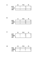
- FIG. 10 is a diagram showing an example of specific numerical values of the weighting coefficient of the white balance value of the image captured by the imaging device 11 installed at the nine installation locations shown in FIG.
- the weighting coefficients of the imaging devices 11 installed at the nine installation locations are as follows.
- the weighting coefficient of the imaging device 11 installed in the center front CF is “3” as shown in FIG.
- the weighting coefficient of the imaging device 11 installed in the left front part LF, the right front part RF, and the central intermediate part CM is “2”.
- the weighting coefficient of the imaging device 11 installed in the left intermediate part LM, the right intermediate part RM, the left rear part LR, the central rear part CR, and the right rear part RR is “1”.
- the weighting of the imaging device 11 installed in the central intermediate portion CM is performed.
- the coefficient increases from “3” to “4”.
- the weighting coefficients of the other imaging devices 11 do not change.
- the weighting coefficient of the imaging device 11 installed in the central intermediate part CM increases from “4” to “8”. Further, the weighting coefficient of the imaging device 11 installed in the left front part LF, the right front part RF, and the central intermediate part CM increases from “2” to “4”. In addition, the weighting coefficient of the imaging device 11 installed in the left intermediate part LM and the right intermediate part RM increases from “1” to “2”. The weighting coefficients of the other imaging devices 11 do not change.
- the weighting coefficients of the imaging devices 11 installed at the nine installation locations are opposite to those in the forward traveling state although not shown.
- the weighting coefficients of the imaging devices 11 installed at the nine installation locations are as follows.
- the weighting coefficient of the imaging device 11 installed in the central rear CR is “3”.
- the weighting coefficient of the imaging device 11 installed in the left rear part LR, the right rear part RR, and the central intermediate part CM is “2”.
- the weighting coefficient of the imaging device 11 installed in the left intermediate part LM, the right intermediate part RM, the left front part LF, the center front part CF, and the right front part RF is “1”.
- the weighting coefficient of the imaging device 11 installed in the central intermediate portion CM is “3” to “4”. To increase. The weighting coefficients of the other imaging devices 11 do not change.
- the weighting coefficient of the imaging device 11 is as follows.
- the weighting coefficient of the imaging device 11 installed in the central intermediate part CM increases from “4” to “8”. Further, the weighting coefficients of the imaging devices 11 installed in the left rear part LR, the right rear part RR, and the central intermediate part CM are increased from “2” to “4”. In addition, the weighting coefficient of the imaging device 11 installed in the left intermediate part LM and the right intermediate part RM increases from “1” to “2”.
- the weighting coefficients of the other imaging devices 11 do not change.
- the weighting coefficients of all the imaging devices 11 return to “1” in the initial state.
- the average value calculation unit 2006 calculates the average value of the individual white balance values of the respective imaging devices 11 weighted by the weighting unit 2005.
- An average value calculation unit 2006 calculates an average value by dividing the sum of the weighted individual white balance values by the total number of imaging devices 11.
- the average value of the calculated white balance values is the target white balance value described above, and is a white balance value common to all the imaging devices 11.
- the calculated average value of the white balance values is given as a target white balance value to the white balance correction unit 107 of each imaging device 11 via the communication unit 2011 described later and the communication unit 1085 of the imaging device 11.
- FIG. 11 is a diagram illustrating an example of a change in color temperature weighted according to the weighting coefficient illustrated in FIG. 10 with respect to the color temperature of the image captured by each imaging device 11, the vertical axis is the color temperature, and the horizontal axis Is the elapsed time when the color temperature changes.
- FIG. 11 shows the change in the color temperature. Since the color temperature is a value corresponding to the white balance value as described above, the change in the color temperature shown in FIG. 11 represents the change in the white balance value. Become.
- the color temperature TCF is the color temperature of an image captured by the imaging device 11 provided at the location of the central front CF shown in FIG.
- the color temperature TLM is the color temperature of an image captured by the imaging device 11 provided at the location where the left intermediate portion LM shown in FIG.
- the color temperature TRM is the color temperature of an image captured by the imaging device 11 provided at the location where the right intermediate portion RM illustrated in FIG.
- the color temperature TCR is the color temperature of an image captured by the imaging device 11 provided at the location of the central rear CR shown in FIG.
- the color temperature TT is an average value of the color temperatures of the images picked up by the respective image pickup devices 11. Therefore, the change in the color temperature TT shown in FIG. 11 represents the average value of the white balance values calculated by the average value calculation unit 2006, that is, the change in the target white balance value.
- FIG. 11A shows a case where the weighting coefficient shown in FIG. 10A is applied to the color temperature of the image taken by each imaging device 11, and FIG. 11B shows the case where FIG. This is a case where the weighting coefficient shown in FIG. FIG. 11C shows the case where the weighting coefficient shown in FIG. 10C is applied, and FIG. 11D shows the case where the weighting coefficient shown in FIG. 10D is applied.
- the average value of the color temperature TT is captured by the imaging device 11 disposed in the central front CF as time passes. Approaches the color temperature of the printed image.
- the average value of the color temperature TT approaches the color temperature of the image captured by the imaging device 11 disposed in the central rear CR as time passes.
- the weight of the individual white balance value of the image obtained by capturing the traveling direction of the vehicle, which is watched by the driver of the vehicle increases.
- the weighting coefficient is set so that the weight of the individual white balance value of the image obtained by capturing the traveling direction of the vehicle with respect to the target white balance value increases with the passage of time when the running state of the vehicle does not change.
- the white balance control unit 200 includes a correction determination unit 2007, a correction speed calculation unit 2008, a first vehicle surrounding environment determination unit 2009, a second vehicle surrounding environment determination unit 2010, and a communication unit 2011.
- the correction determination unit 2007 determines whether or not to correct the individual white balance value of each imaging device 11 to the target white balance value.
- the white balance value of the subject image captured by each imaging device 11 can change as the vehicle moves. It is estimated that the nature is large. For this reason, if the white balance value of the image captured by each imaging device 11 is corrected strictly following the variation of the white balance value, the white balance value may fluctuate drastically. In this case, an image in which the white balance value fluctuates violently may give a viewer discomfort.
- the correction determination unit 2007 determines that the target white balance value calculated within a predetermined time is within the predetermined range and the target white balance value is stable, Correct the value. On the other hand, the correction determination unit 2007 corrects the white balance value when it is determined that the target white balance value calculated within the predetermined time is not within the predetermined range and the target white balance value is unstable. Without changing, the white balance value until then is maintained.
- the correction determination unit 2007 corrects the white balance value without determining whether or not the target white balance value is stable immediately after the vehicle is indoors or outdoors or just after entering or exiting the tunnel.
- the correction determination unit 2007 determines the start, continuation, and end of the white balance value correction process based on the engine start / stop notification given from the ECU (not shown) via the ECU-IF 205 described later.
- the correction determination unit 2007 determines the start of the correction process when the ECU is notified of the engine start via the ECU-IF 205. Thereby, the control part 12 starts a correction process.
- the correction determination unit 2007 determines the end of the correction process when the ECU notifies the engine stop via the ECU-IF 205. Thereby, the control part 12 complete
- the correction determination unit 2007 determines that the correction process is continued when the ECU is notified of the engine stop via the ECU-IF 205. Thereby, the control part 12 performs a correction process continuously.
- the correction speed calculation unit 2008 calculates a correction speed for correcting the individual white balance value to the target white balance value for each imaging device 11.
- Each imaging device 11 varies in correction time for correcting the white balance value due to manufacturing variations.
- the individual white balance values of the respective imaging devices 11 are different from each other, the difference between the individual white balance value and the target white balance value is different.
- each imaging device 11 the time until the correction is completed from the individual white balance value to the target white balance value is different. Therefore, when the images of the respective imaging devices 11 corrected to the target white balance value are displayed in an appropriate combination, an image in which the white balance value is corrected fast and an image in which the white balance value is corrected slowly may occur. As a result, the displayed image may give the viewer a sense of discomfort.
- the correction speed calculation unit 2008 calculates the correction speed so that the correction of the white balance value is completed with a target correction time common to the imaging apparatuses 11. That is, the correction speed calculation unit calculates the correction speed for each imaging device 11 so that the individual white balance value of each imaging device 11 is simultaneously corrected to the target white balance value.
- the correction speed calculation unit 2008 calculates the correction speed according to the following procedure.
- the correction speed calculation unit 2008 first acquires the individual white balance value of each imaging device 11 via the communication units 1085 and 2011. The correction speed calculation unit 2008 calculates the difference between the acquired individual white balance value and the target white balance value. The correction speed calculation unit 2008 calculates the correction speed by dividing the difference between the individual white balance value and the target white balance value by the target correction time.
- the calculated correction speed is given to the white balance correction unit 107 of each imaging apparatus 11 via the communication units 1085 and 2011.
- determination part 2009 specifies the present position of a vehicle based on the information from the GPS satellite received with the GPS (Global Positioning System: Global Positioning Network) receiver 7 mounted in the vehicle.
- the first vehicle surrounding environment determination unit 2009 compares the current position of the vehicle with the map data provided in the first vehicle surrounding environment determination unit 2009 to determine whether the current vehicle has entered or exited the tunnel or entered the tunnel. .
- the second vehicle surrounding environment determination unit 2010 determines whether the vehicle is currently indoors or outdoors or enters / exits the tunnel based on the IR sensor signal obtained by the IR sensor 3 and given from the imaging device 11. Generally, the amount of infrared light inside and outside the tunnel is different from that inside and outside the tunnel.
- the second vehicle surrounding environment discriminating unit 2010 calculates a change in the amount of infrared light when the vehicle enters or exits the inside or outside of the tunnel based on the IR sensor signal.
- the second vehicle surrounding environment discriminating unit 2010 discriminates whether the vehicle is in or out of the vehicle or enters or exits the tunnel based on the calculated change in the amount of infrared light.
- the vehicle surrounding environment discriminating unit 2009 and the second vehicle surrounding environment discriminating unit 2010 discriminate whether the inside / outside or inside / outside of the tunnel is in / out, the vehicle has entered / outside the inside / outside of the tunnel Determine.
- the white balance control unit 200 may include either the first vehicle surrounding environment determination unit 2009 or the second environment determination unit 20109, and may determine whether the vehicle is indoors or out of the vehicle or in and out of the tunnel.
- the communication unit 2011 controls input / output of information between the imaging device 11 and the control unit 12, and transmits necessary information between the imaging control unit 108 of the imaging device 11 and the white balance control unit 200 of the control unit 12. Communicate by wire or wireless.
- the ECU-IF 205 performs wired or wireless communication between the white balance control unit 200 and the ECU, and sends signals indicating start and stop of the engine, which are commands for starting and stopping the process of correcting the white balance value, from the ECU. Receive.
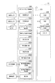
- FIG. 12 is a flowchart showing the procedure of the correction process after the process of correcting the individual white balance value to the target white balance value is started.
- steps S1201 to S1209 are processes executed by the respective imaging devices 11, and the processes shown in steps S1301 to 1315 are processes executed by the control unit 12.
- step S1201 the imaging unit 100, the analog image signal processing unit 101, the A / D conversion unit 102, and the image input controller 103 execute the following processing to acquire digital image data of the subject.
- the imaging unit 100 captures an object and generates an analog image signal of the object.
- the analog image signal processing unit 101 amplifies the generated analog image signal.
- the A / D conversion unit 102 converts the amplified signal into digital image data.
- the image input controller 103 captures the digital image data and stores the captured digital image data in the RAM 105 via the bus 104.
- step S1202 the white balance calculation unit 1082 creates a histogram of RGB values in the acquired digital image data, and calculates an individual white balance value of the acquired digital image data based on the generated histogram.
- the communication unit 1085 transmits the calculated individual white balance value to the control unit 12 in step S1203.
- control unit 12 Next, the process executed by the control unit 12 will be described, and a series of processes executed by the control unit 12 will be described.
- step S1301 the communication unit 2011 of the control unit 12 receives and acquires the individual white balance value of each imaging device 11 transmitted from the communication unit 1085 of the imaging device 11.
- step S1302 the vehicle speed detection unit 2001 acquires a vehicle speed signal from the vehicle speed sensor 4, and detects the vehicle speed based on the vehicle speed signal.
- step S1303 the steering angle detection unit 2002 acquires a steering angle signal from the steering angle sensor 5, and detects the steering angle based on the steering angle signal.
- step S1304 the shift lever position detection unit 2003 acquires a shift lever position signal from the shift lever sensor 6, and detects the position of the shift lever based on the shift lever position signal.
- step S1305 the vehicle travel state determination unit 2004 sets the stop state, the forward state, the reverse state, the turning state, and the temporarily changed state as the vehicle travel state based on the detected vehicle speed, the steering angle, and the position of the shift lever. Determine.
- step S1305 the vehicle travel state determination unit 2004 determines a duration time during which the forward state and the reverse state are continued.
- the weighting unit 2005 refers to the weighting coefficient stored in the weighting coefficient ROM 204 based on the traveling state of the vehicle, and multiplies the individual white balance value given from each imaging device 11 by the weighting coefficient. Weight.
- step S1307 the average value calculation unit 2006 calculates an average value of the weighted individual white balance values of the imaging devices 11, and sets the calculated average value as the target white balance value.
- the first vehicle surrounding environment discriminating unit 2009 discriminates whether or not the current vehicle has entered / exited the inside or outside of the tunnel or the tunnel based on the information from the GPS satellite and the map data in step S1308.
- second vehicle ambient environment determination unit 2010 determines whether the vehicle is currently indoors or outdoors or has entered or exited a tunnel based on the IR sensor signal.
- step S1309 the correction determination unit 2007 determines whether to correct the individual white balance value of each imaging device 11 to the target white balance value. As a result of the determination, if it is determined not to correct (in the case of NO), the process shown in step S1310 is executed.
- step S1311 is executed.
- step S1310 the communication unit 2011 of the control unit 12 transmits to the imaging devices 11 that the individual white balance value is not corrected to the target white balance value. Thereafter, the process shown in step S1315 is executed.
- the correction speed calculation unit 2008 sets the individual white balance value for each imaging device 11 in step S1311, and the target white balance value. The correction speed for correcting to is calculated.
- step S1312 the communication unit 2011 of the control unit 12 transmits information indicating that the individual white balance value is corrected to the target white balance value to each imaging device 11. Thereafter, the communication unit 2011 of the control unit 12 transmits the calculated target white balance value and correction speed to each imaging device 11 in step S1313.
- step S1204 the communication unit 1085 of the imaging apparatus 11 receives and acquires a determination result as to whether or not to correct the white balance value transmitted from the communication unit 2011 of the control unit 12.
- step S1205 the white balance correction unit 107 determines whether to correct the white balance value based on the determination result of whether to correct the acquired white balance value. That is, the white balance correction unit 107 does not correct the white balance value when the determination result indicating that the white balance value is not corrected is acquired (in the case of NO). Thereafter, the process shown in step S1209 is executed. On the other hand, the white balance correction unit 107 corrects the white balance value when the determination result indicating that the white balance value is corrected is acquired (in the case of YES). Thereafter, the process shown in step S1206 is executed.
- step S1206 the communication unit 1085 receives and acquires the target white balance value and the correction speed transmitted from the communication unit 2011 of the control unit 12 in the process shown in step S1311.
- step S1207 the white balance correction unit 107 corrects the individual white balance value to the target white balance value according to the correction speed calculated for each imaging device 11.
- the white balance correction unit 107 transmits to the control unit 12 that the correction of the white balance value is completed via the communication unit 1085 in step S1208. Thereafter, the process shown in step S1209 is executed.
- step S1209 the correction determination unit 1083 determines whether to continue or end the white balance value correction processing based on the notification of engine start and stop. As a result of the determination, when it is determined that the correction process is to be continued (in the case of YES), the process shown in step S1201 is executed. On the other hand, when it is determined that the correction process is to be ended (in the case of NO), a series of processes executed by each imaging device 11 is ended.
- step S ⁇ b> 1314 the communication unit 2011 receives and acquires a notification that the correction of the white balance value has been completed from each imaging device 11.
- step S1315 the correction determination unit 2007 determines whether to continue or end the white balance value correction process based on the notification of engine start and stop. As a result of the determination, when it is determined that the correction process is to be continued (in the case of YES), the process shown in step S1301 is executed. On the other hand, when it is determined that the correction process is to be ended (in the case of NO), a series of processes executed by the control unit 12 is ended.
- the individual white balance value of each imaging device 11 is corrected to the target white balance value.
- the various predetermined values, the predetermined time, and the predetermined range are values within the range of design matters that can be determined by, for example, desktop analysis such as experiments or simulations using an actual vehicle. It can set suitably according to the contents of processing performed with reference.
- the imaging system 1 can obtain the following effects by including the following technical features.
- the imaging system 1 is mounted on the same moving body, calculates a target white balance value common to a plurality of imaging devices 11 that capture an image of a subject and acquire an image, and images acquired by the imaging devices 11. And a control unit 12.
- Each imaging device 11 includes a white balance calculation unit 1082 that calculates an individual white balance value of an image acquired by the imaging device 11.
- Each imaging device 11 includes a white balance correction unit 107 that corrects an individual white balance value of a subject image captured by each imaging device 11 to a target white balance value based on the target white balance value.
- the control unit 12 includes a weighting unit 2005 that individually weights the individual white balance value given from each imaging device 11 based on the weighting coefficient set for each imaging device 11.
- the control unit 12 includes an average value calculation unit 2006 that calculates an average value of the weighted individual white balance values and uses the average value of the individual white balance values as a target white balance value.
- the imaging system 1 takes into account the characteristics of each imaging device 11 as compared with the conventional case where the white balance values of the plurality of imaging devices 11 are simply averaged. A target white balance value common to each imaging device 11 can be calculated.
- the image pickup system 1 can present a viewer with an image in which the white balance value is optimally adjusted. It becomes possible.
- the control unit 12 performs correction for individually calculating the correction speed for correcting the individual white balance value to the target white balance value for each imaging device 11 so that the individual white balance value is simultaneously corrected to the target white balance value.
- a speed calculation unit 2008 is provided.
- the white balance correction unit 107 corrects the individual white balance value of the subject image captured by the imaging device 11 to the target white balance value based on the correction speed calculated by the correction speed calculation unit 2008.
- the imaging system 1 can simultaneously correct the individual white balance value of each imaging apparatus 11 to the target white balance value. As a result, when a plurality of images captured by each imaging device 11 are displayed on one display device 2, an image corrected to the target white balance value and an image not corrected are displayed together. This is avoided. As a result, the imaging system 1 can present an image without a sense of incongruity to the viewer.
- the control unit 12 includes a correction determination unit 2007 that determines that the individual white balance is corrected to the target white balance when the target white balance value calculated within a predetermined period is within a predetermined range.
- the imaging system 1 can avoid the target white balance value from fluctuating violently, and give unpleasant feeling to the viewer of the image corrected to the target white balance value. It is possible to present an image without any.
- Each imaging device 11 is mounted on a vehicle, and the weighting unit 2005 changes the weighting coefficient according to the running state of the vehicle.
- the imaging system 1 can change the weighting of the individual white balance value of each imaging device 11 according to the traveling state of the vehicle, such as the vehicle moving forward or turning. . Thereby, the target white balance value can be calculated according to the running state of the vehicle.
- the imaging system 1 can increase the ratio of the individual white balance value of the imaging device 11 that captures the traveling direction of the vehicle to the target white balance value. For example, when the vehicle is moving forward, the weight of the individual white balance value of the image captured in front of the vehicle is greater than the individual white balance value of other images other than the image captured in front of the vehicle.
- the imaging system 1 can obtain an image of the target white balance value in which the proportion of the individual white balance value of the image obtained by imaging the traveling direction of the vehicle being watched by the driver of the vehicle is high.
- the imaging system 1 displays a plurality of images captured by each imaging device 11 on one display device 2, an image obtained by capturing a real scene in the traveling direction of the vehicle being watched by the driver of the vehicle.
- An image having a target white balance value close to the white balance value can be presented.
- the imaging system 1 can present an image with less discomfort when the driver of the vehicle visually recognizes the image corrected to the target white balance value.
- the weighting unit 2005 changes the weighting coefficient based on the time during which the vehicle is running.
- the imaging system 1 can increase the weighting coefficient of each imaging device 11 as the current running state of the vehicle becomes longer. Thereby, the target white balance value can be calculated in consideration of the duration of the running state of the vehicle. As a result, the imaging system 1 can obtain an image of the target white balance value in which the ratio of the individual white balance value of the image obtained by imaging the traveling direction of the vehicle being watched by the driver of the vehicle is high. As a result, as described above, the imaging system 1 can present an image with less discomfort when the driver of the vehicle visually recognizes the image corrected to the target white balance value.
- Each part shown in FIG. 7 or FIG. 8 may be configured by hardware, and a part that can be configured by software may be configured by software. Use of hardware and software is optional.
- the hardware may be an integrated circuit.
- the present invention can be used for an arbitrary moving body that images a subject in a plurality of directions by a plurality of imaging devices.
Landscapes
- Engineering & Computer Science (AREA)
- Multimedia (AREA)
- Signal Processing (AREA)
- Color Television Image Signal Generators (AREA)
- Studio Devices (AREA)
- Processing Of Color Television Signals (AREA)
- Closed-Circuit Television Systems (AREA)
Abstract
撮像システム(1)は、同一の移動体に搭載され、被写体を撮像して画像を取得する複数の撮像装置(11)と、各撮像装置(11)で取得された画像に対して共通した目標ホワイトバランス値を算出する制御部(12)とを備えている。各撮像装置(11)は、撮像装置(11)で取得した画像の個別ホワイトバランス値を算出するホワイトバランス算出部(1082)と、各撮像装置(11)で撮像された被写体の画像の個別ホワイトバランス値を目標ホワイトバランス値に補正するホワイトバランス補正部(107)とを備えている。制御部(12)は、各撮像装置(11)から与えられた個別ホワイトバランス値に対して、それぞれ個別に重み付けする重み付け部(2005)を備えている。
Description
本開示は、複数の撮像装置で撮像された被写体の画像のホワイトバランス値を補正する撮像システムに関する。
従来、この種の技術としては、特許文献1に記載されたものが知られている。特許文献1には、テレビ放送用の複数の撮像カメラのホワイトバランスを調整するカメラシステムが記載されている。
このカメラシステムでは、撮像前に各撮像カメラにおいて白い被写体を撮像して得られたホワイトバランス情報が平均化される。平均化されたホワイトバランス情報はすべての撮像カメラに送信され、すべての撮像カメラはそれぞれ平均化されたホワイトバランス情報に基づいてホワイトバランスを調整する。
複数の撮像カメラが同一の移動体の異なる場所に設置されている場合には、各撮像カメラが撮像する被写体の画像の明るさなどが、各撮像カメラ毎に頻繁かつ激しく変化する可能性がある。
このような場合に、従来のカメラシステムで採用された技術では、単に各撮像カメラのホワイトバランス情報が平均化されているだけで、各撮像カメラ毎の特性が考慮されていなかった。このため、従来のカメラシステムでは、各撮影カメラで撮像された画像のホワイトバランス値を最適に共通化するのが困難になっていた。
実施形態の目的は、移動体に設置された複数の撮像装置で撮像された被写体の画像のホワイトバランス値を最適に共通化して補正することができる撮像システムを提供することである。
実施形態の一態様によれば、同一の移動体に搭載され、被写体を撮像して画像を取得する複数の撮像装置と、前記各撮像装置で取得された画像に対して共通した目標ホワイトバランス値を算出する制御部とを備え、前記各撮像装置は、前記撮像装置で取得した画像の個別ホワイトバランス値を算出するホワイトバランス算出部と、目標ホワイトバランス値に基づいて、前記各撮像装置で撮像された被写体の画像の個別ホワイトバランス値を目標ホワイトバランス値に補正するホワイトバランス補正部とを有し、前記制御部は、前記撮像装置毎に設定された重み付け係数に基づいて、前記各撮像装置から与えられた個別ホワイトバランス値に対して、それぞれ個別に重み付けする重み付け部と、重み付けされた個別ホワイトバランス値の平均値を算出し、個別ホワイトバランス値の平均値を前記目標ホワイトバランス値とする平均値算出部とを有することを特徴とする撮像システムが提供される。
実施形態の撮像システムによれば、移動体に設置された複数の撮像装置で撮像された被写体の画像のホワイトバランス値を最適に共通化して補正することができる。
以下、図面を用いて実施形態を説明する。
(実施形態)
まず、図1を参照して、実施形態に係る撮像システムの全体構成を説明する。
まず、図1を参照して、実施形態に係る撮像システムの全体構成を説明する。
撮像システム1は、複数の撮像装置11と制御部12とを備えている。撮像システム1は、例えば4つの撮像装置11が1つの制御部12に共通に接続されて構成されている。各撮像装置11は、例えば車両や船舶、飛行体などの同一の移動体に搭載され、被写体を撮像して画像データを得る。
以下に説明する実施形態では、複数の撮像装置11及び制御部12は車両に搭載された場合を一例として説明する。したがって、以下に記載された車両とは、撮像システム1が搭載された車両を指すものとする。
制御部12は、図1に示すシステム構成では、複数の撮像装置11に対して別体として設けられているが、図2に示すように、複数の撮像装置11のいずれか1つの撮像装置11内に設けられ、1つの撮像装置11と一体化されていてもよい。
各撮像装置11と制御部12との間では、有線や無線などの通信により必要な情報が伝送される。
撮像システム1は、各撮像装置11に対して共通となる目標ホワイトバランス値を算出し、各撮像装置11が個別に算出した個別ホワイトバランス値を目標ホワイトバランス値に補正する。各撮像装置11で撮像されて目標ホワイトバランス値に補正された画像は、適宜組み合わされて各撮像装置11に接続された表示装置2に表示することができる。すなわち、表示装置2に各撮像装置11で撮像された複数の画像が表示される際に、表示される複数の画像のホワイトバランス値はすべて目標ホワイトバランス値に統一される。
なお、表示装置2は、図1及び図2では1つしか記載されていないが、複数であってもよい。
図3は車両の運転席周囲の様子を模式的に表した図である。
表示装置2は、図3に示すように、撮像装置11で撮像された画像を表示する液晶ディスプレイなどで構成された例えばデジタルルームミラー31やデジタルサイドミラー32(32-L,32-R)で構成される。また、表示装置2は、図3に示す例えばナビゲーションシステムにおいて地図情報などを表示する液晶ディスプレイで構成されたナビゲーションディスプレイ33で構成される。
また、表示装置2としては、図3には図示していないが、例えばフロントガラスに画像を表示するヘッドアップディスプレイや、ダッシュボードに配置された計器類に隣接して配置され車両の周囲の画像を表示するクラスターディスプレイなどで構成される。
表示装置2は、上記に限らず各撮像装置11で撮像された画像を表示できる表示装置であれば、どのような構成の表示装置であってもよい。
図4はデジタルルームミラー31に表示される画像の一例を示す図である。
図4において、デジタルルームミラー31には、その中央に車両の後方の画像41が表示されている。デジタルルームミラー31には、画像41の左隣に車両の左後方の画像42が画像41と並んで表示されている。デジタルルームミラー31には、画像41の右隣に車両の右後方の画像43が画像41と並んで表示されている。
図5は撮像システム1が例えば4つの撮像装置11を備えている場合に、車両51における各撮像装置11の設置位置の一例を示す図である。各撮像装置11は、図5に示す設置位置に限らず任意の位置に配置することができる。
デジタルルームミラー31に表示された画像41は、図5に示す車両51の後部に設置された撮像装置11-Rで撮像されたものである。デジタルルームミラー31に表示された画像42は、図5に示す車両51の左側方のドアミラーに設置された撮像装置11-SLで撮像されたものである。デジタルルームミラー31に表示された画像43は、図5に示す車両51の右側方のドアミラーに設置された撮像装置11-SRで撮像されたものである。
左側のデジタルサイドミラー32-Lには、例えば撮像装置11-SLで撮像された画像が表示され、右側のデジタルサイドミラー32-Rには、例えば撮像装置11-SRで撮像された画像が表示される。
図6はナビゲーションディスプレイ33に表示される画像の一例を示す。図6において、ナビゲーションディスプレイ33には、車両51の異なる位置に設置された複数の撮像装置で撮像された画像を合成して生成された、車両51を含む車両周囲の俯瞰画像61が表示されている。
ナビゲーションディスプレイ33に表示された車両51の周囲の俯瞰画像61は、俯瞰画像62~65が組み合わされて構成されている。俯瞰画像62は、車両51の前方の俯瞰画像であり、俯瞰画像63は、車両51の左側方の俯瞰画像であり、俯瞰画像64は、車両51の右側方の俯瞰画像であり、俯瞰画像65は、車両51の後方の俯瞰画像である。
俯瞰画像62は、例えば図5に示す車両51の前部に設置された撮像装置11-Fで撮像された画像に基づいて生成され、俯瞰画像63は、例えば図5に示す撮像装置11-SLで撮像された画像に基づいて生成される。俯瞰画像64は、例えば図5に示す撮像装置11-SRで撮像された画像に基づいて生成され、俯瞰画像65は、例えば図5に示す撮像装置11-Rで撮像された画像に基づいて生成される。
次に、図7を参照して、撮像装置11の構成を説明する。
各撮像装置11は、図7に示すように構成されている。各撮像装置11は、図1に示すシステム構成ではすべて同一構成であるので、1つの撮像装置11を代表して撮像装置11の構成を説明する。
図7において、撮像装置11は、被写体を撮像して、被写体のアナログ画像信号を得る撮像部100を備えている。
撮像部100は、ズームレンズ1001、フォーカスレンズ1002、絞り1003、及びイメージセンサなどで構成される撮像素子1004を備えている。
ズームレンズ1001は図示しないズームアクチュエータによって光軸に沿って移動する。同様に、フォーカスレンズ1002は、図示しないフォーカスアクチュエータによって光軸に沿って移動する。絞り1003は、図示しない絞りアクチュエータに駆動されて動作する。
撮像部100を用いた撮像は以下の手順で行われる。撮像素子1004はズームレンズ1001、フォーカスレンズ1002、及び絞り1003を通過した光を光電変換して、被写体のアナログ画像信号を生成する。生成されたアナログ画像信号は、アナログ画像信号処理部101に与えられる。
アナログ画像信号処理部101は、このアナログ画像信号を増幅した後、A/D変換部102が、その増幅された信号をデジタル画像データに変換する。画像入力コントローラ103は、A/D変換部102から与えられたデジタル画像データを取り込んで、取り込んだデジタル画像データをバス104を介してバス104に接続されたRAM105に記憶させる。
バス104には、デジタル信号処理部106、ホワイトバランス補正部107、撮像制御部108が接続されている。
デジタル信号処理部106は、撮像制御部108の制御の下に、バス104を介してRAM105に格納されたデジタル画像データを読み込み、所定の信号処理を施して輝度信号と色差信号とからなるデータを生成する。
デジタル信号処理部106は、撮像素子1004から出力される撮像時の感度情報、例えばAGCゲインまたはISO感度に基づき、デジタル画像データの各種デジタル補正処理を行う。各種デジタル補正処理は、例えばオフセット処理、ガンマ補正処理、ゲイン処理、RGB補完処理、ノイズ低減処理、輪郭補正処理、色調補正処理、光源種別判定処理等である。
AGCは、Automatic Gain Control:自動利得制御の略称であり、ISOは、International Organization for Standardization:国際標準化機構の略称である。
ホワイトバランス補正部107は、後述する制御部12で算出された目標ホワイトバランス値及び補正速度に基づいて、各撮像装置11で算出された個別ホワイトバランス値を目標ホワイトバランス値に補正する。
撮像制御部108は、バス104を介してROM109に記憶された撮像装置11の全体の動作を制御する制御プログラムを読み出し、読み出した制御プログラムに基づいて撮像装置11の全体の動作を統括制御する。撮像制御部108は、CPUを有するマイクロコンピュータによって構成することができる。
撮像制御部108は、アクチュエータ・センサ制御部1081、ホワイトバランス算出部1082、補正判別部1083、IRセンサ信号取得部1084、通信部1085を備えている。
アクチュエータ・センサ制御部1081は、前述した撮像部100の図示しないズームアクチュエータ、フォーカスアクチュエータ及び絞りアクチュエータの駆動を制御する。アクチュエータ・センサ制御部1081は、撮像素子1004の光電変換動作を制御する。
ホワイトバランス算出部1082は、バス104を介してRAM105に記憶されたデジタル画像データを参照し、デジタル画像データの色情報のR(赤)G(緑)B(青)値の分布を測定する。ホワイトバランス算出部1082は、分布を測定しようとするデジタル画像データを複数の領域に分割し、分割した領域毎にRGB値の平均値を求めてヒストグラムを作成することで、デジタル画像データのRGB値の分布を測定する。
ホワイトバランス算出部1082は、作成したヒストグラムと、予め用意されたホワイトバランス算出用テーブルのヒストグラムとを照合するパターンマッチング処理を行う。このホワイトバランス算出用テーブルは、RGB値の分布を表したヒストグラムとホワイトバランス値及び画像の色温度との対応関係を示すテーブルであり、記憶装置、例えばROM109に記憶されて予め用意される。
ホワイトバランス算出部1082は、パターンマッチング処理の結果、作成したヒストグラムに一致する、または最も近いヒストグラムに対応したホワイトバランス値をデジタル画像データのホワイトバランス値として算出する。この算出されたホワイトバランス値は、撮像装置11毎に個別に算出される個別ホワイトバランス値となる。
なお、ホワイトバランス算出部1082は、ホワイトバランス値に代えてデジタル画像データの色温度を算出し、色温度からホワイトバランス値を算出するようにしてもよい。また、ホワイトバランス算出部1082は、ホワイトバランス値と色温度との双方を算出してもよい。
ホワイトバランス値と色温度との対応関係は、撮像部100のレンズ類(ズームレンズ1001、フォーカスレンズ1002)や、撮像素子1004、フィルタ(図示せず)などの特性に依存する。このため、ホワイトバランス値と色温度との対応関係は、撮像装置11毎に固有なものとなるので、各撮像装置11の生産時に各撮像装置11のホワイトバランス用ROM110に予め記憶しておく。
以下の説明では、ホワイトバランス算出部1082は、ヒストグラムから個別ホワイトバランス値のみを算出し、算出した個別ホワイトバランス値に基づいて後述する各種処理を行って目標ホワイトバランス値を算出するものとする。
補正判別部1083は、制御部12を介してECU(エンジン・コントロール・ユニット)(図示せず)から与えられるエンジンの始動、停止の通知に基づいて、個別ホワイトバランス値の補正処理の開始、継続及び終了を判別する。ECUは、電子制御された装置によりエンジンの運転を制御する際に、それらを統括制御する装置である。
補正判別部1083は、制御部12を介してECUからエンジンの始動が通知されると補正処理の開始を判別する。これにより、撮像制御部108及びホワイトバランス補正部107は補正処理を開始する。補正判別部1083は、制御部12を介してECUからエンジンの停止が通知されると補正処理の終了を判別する。これにより、撮像制御部108及びホワイトバランス補正部107は補正処理を終了する。
補正判別部1083は、補正処理が開始された後、制御部12を介してECUからエンジンの停止が通知されまでは補正処理を継続するものと判別する。これにより、撮像制御部108及びホワイトバランス補正部107は、補正処理を継続して行う。
補正判別部1083は、補正処理が開始された後、制御部12を介してECUからエンジンの停止が通知されまでは補正処理を継続するものと判別する。これにより、撮像制御部108及びホワイトバランス補正部107は、補正処理を継続して行う。
IRセンサ信号取得部1084は、IR(赤外線)センサ3で得られたIRセンサ信号を取得する。IRセンサ3は、受光した赤外線を電気信号に変換し、変換で得られた電気信号をIRセンサ信号としてIRセンサ信号取得部1084に与える。IRセンサ3は、各撮像装置11が搭載された車両に設けられている。
IRセンサ信号取得部1084は、取得したIRセンサ信号を通信部1085を介して制御部12に与える。IRセンサ信号は、後述するように車両の周囲の環境を把握するために用いられる。
通信部1085は、撮像装置11と制御部12との間の情報の入出力を制御し、撮像装置11と制御部12との間で必要な情報を有線または無線で通信する。
バス104には、入出力I/F111を介して入出力端子112が接続されている。入出力端子112には、表示装置2が接続される。
次に、図8を参照して、制御部12の構成を説明する。
制御部12は、図8に示すように構成されている。図8において、制御部12は、ホワイトバランス制御部200を備えている。
ホワイトバランス制御部200は、バス201を介してROM202に記憶された制御部12の全体の動作を制御する制御プログラムを読み出し、読み出した制御プログラムに基づいて制御部12の全体の動作を統括制御する。ホワイトバランス制御部200は、CPUを有するマイクロコンピュータによって構成することができる。
バス201には、ホワイトバランス制御部200及びROM202の他に、RAM203、重み付け係数用ROM204及びECU-IF205が接続されている。
ホワイトバランス制御部200は、バス201を介して以下に示す各種処理を行う際に必要となるデータを記憶するRAM203、及び重み付け係数用ROM204との間でデータの入出力を行い、各種処理を実行する。
ホワイトバランス制御部200は、車速検出部2001、舵角検出部2002、シフトレバーポジション検出部2003、車両走行状態判別部2004、重み付け部2005、平均値算出部2006を備えている。
車速検出部2001は、車両に設けられた車速センサ4から与えられた車速信号に基づいて、車速を検出する。車速信号は、ECUなどに与えられる車速に応じた電気信号である。
舵角検出部2002は、車両に設けられた舵角センサ5から与えられた舵角信号に基づいて、車両の旋回角度を検出する。舵角信号は、ECUなどに与えられる車両の舵角に応じた電気信号である。
シフトレバーポジション検出部2003は、車両に設けられたシフトレバーセンサ6から与えられたシフトレバーポジション信号に基づいて、シフトレバーのポジション(シフトレンジ)を検出する。シフトレバーポジション信号は、ECUなどに与えられるシフトレバーのポジションを示す電気信号である。
シフトレバーポジション信号は、シフトレバーが車両が前進するレンジである例えばD(ドライブ)レンジ、または車両が後進するレンジであるR(リバース)レンジにあることを示す電気信号である。また、シフトレバーポジション信号は、シフトレバーが車両がP(駐車状態)レンジにあることを示す電気信号である。
車両走行状態判別部2004は、車速検出部2001で検出された車速、舵角検出部2002で検出された舵角、シフトレバーポジション検出部2003で検出されたシフトレバーのポジションに基づいて、車両の走行状態を判別する。また、車両走行状態判別部2004は、検出された車速及び舵角が継続している継続時間に基づいて、車両の走行状態を判別する。
車両走行状態判別部2004は、シフトレバーのポジションが車両が前進するレンジにあり、車速の変動量が所定値以下であり、かつこのような状態が所定時間以上継続している場合には、車両は前進しているものと判別する。あるいは、車両走行状態判別部2004は、シフトレバーのポジションが車両が前進するレンジにあり、車速の変動量が所定値以上、旋回角度の変動量が所定値以下、かつこのような状態が所定時間継続している場合には、車両は前進しているものと判別する。ここでは、この走行状態を前進状態と呼ぶ。
車両走行状態判別部2004は、前進状態が第1所定時間継続しているか否かを判別する。また、車両走行状態判別部2004は、前進状態が第2所定時間継続しているか否かを判別する。第2所定時間は第1所定時間よりも長く設定される。
車両走行状態判別部2004は、シフトレバーの位置がRレンジにあり、車速の変動量が所定値以下であり、かつこのような状態が所定時間以上継続している場合には、車両は後進しているものと判別する。あるいは、車両走行状態判別部2004は、シフトレバーの位置がRレンジにあり、車速の変動量が所定値以上、旋回角度の変動量が所定値以下、かつこのような状態が所定時間継続している場合には、車両は後進しているものと判別する。ここでは、この走行状態を後進状態と呼ぶ。
車両走行状態判別部2004は、後進状態が第3所定時間継続しているか否かを判別する。また、車両走行状態判別部2004は、後進状態が第4所定時間継続しているか否かを判別する。第4所定時間は第3所定時間よりも長く設定される。
車両走行状態判別部2004は、車速が所定値以上の減少を続け、同時にもしくはその後旋回角度の変動量が所定値以上の場合には、車両は交差点などで旋回を開始したものと判別する。ここでは、この走行状態を旋回状態と呼ぶ。
車両走行状態判別部2004は、車速の変動量が所定値以下、かつ旋回角度の変動量が所定値以下である場合には、車両はカーブなどで旋回している、または車線を変更しているものと判別する。ここでは、この走行状態を一時的変化状態と呼ぶ。
車両走行状態判別部2004は、シフトレバーのポジションがPレンジにある場合、または車速が「0」の場合には、車両は停車状態にあるものと判別する。
重み付け部2005は、車両走行状態判別部2004で判別された車両の走行状態に基づいて、各撮像装置11から与えられた個別ホワイトバランス値に重み付け係数を乗算して重み付けを行う。
重み付け係数は、予め任意に設定されて用意され、重み付け係数用ROM204に記憶される。なお、重み付け係数は、重み付け係数用ROM204に代えてROM202などの他の記憶装置に記憶してもよい。
車両が前進状態にある場合に、車両の前部に設置された撮像装置11で撮像された画像のホワイトバランス値の重み付け係数は、他の撮像装置11で撮像された画像のホワイトバランス値の重み付け係数よりも大きくする。車両が前進状態にある場合に、車両の前部に設置された撮像装置11で撮像された画像のホワイトバランス値の重み付け係数は、車両が前進状態にある継続時間が長くなるほど増加する。増加する重み付け係数には、予め上限値が設けられる。
撮像装置11が設置される車両の前部としては、例えばフロントバンパーなどがあげられる。
車両が後進状態にある場合に、車両の後部に設置された撮像装置11で撮像された画像のホワイトバランス値の重み付け係数は、他の撮像装置11で撮像された画像のホワイトバランス値の重み付け係数よりも大きくする。車両が後進状態にある場合に、車両の後部に設置された撮像装置11で撮像された画像のホワイトバランス値の重み付け係数は、車両が後進状態にある継続時間が長くなるほど増加する。増加する重み付け係数には、予め上限値が設けられる。
撮像装置11が設置される車両の後部としては、例えばリアバンパーやバックドアなどがあげられる。
車両が旋回状態または停車状態にある場合には、重み付け係数は初期状態に戻り、各撮像装置11で撮像された画像のすべてのホワイトバランス値の重み付け係数は同一になる。
車両が一時的変化状態にある場合には、重み付け係数は、それまでの重み付け係数が継続されて維持される。
図9は車両に設置される撮像装置11の設置場所を特定する際に設定された設置場所の区分けを示す図である。
図9において、設置場所の区分けは車両91を上から見たときに例えば9つに区分けされている。ここでは、車両91を車両91の前後方向に対して前部、中間部、後部の3つに分け、車両91の左右方向に対して左、中央、右の3つに分けるものとする。この場合に、9つの設置場所の区分けは、図9に示すように、左前部LF、中央前部CF、右前部RF、左中間部LM、中央中間部CM、右中間部RM、左後部LR、中央後部CR、右後部RRとする。
なお、上記の設置場所の区分け例は一例であり、区分けの数ならびに区分けの仕方は任意に決めることができる。
車両91に搭載される撮像装置11としては、少なくとも車両91の前方を撮像する撮像装置11と車両の後方を撮像する撮像装置11とが搭載される。車両の前方を撮像する撮像装置11は、図9に示す区分け例では例えば左前部LF、中央前部CF、右前部RF、中央中間部CMのいずれかの設置場所に設置される。車両の後方を撮像する撮像装置11は、図9に示す区分け例では例えば左後部LR、中央後部CR、右後部RR、中央中間部CMのいずれかの設置場所に設置される。
車両の左側方を撮像する撮像装置11を搭載する場合には、図9に示す区分け例では例えば左前部LF、左中間部LM、左後部LRのいずれかの設置場所に設置される。
車両の右側方を撮像する撮像装置11を搭載する場合には、図9に示す区分け例では例えば右前部RF、右中間部RM、右後部RRのいずれかの設置場所に設置される。
図10は図9に示す9つの設置場所に設置される撮像装置11で撮像された画像のホワイトバランス値の重み付け係数の具体的な数値の一例を示す図である。
図10において、重み付け係数が初期状態ですべて同一の場合には、図10(a)に示すようにすべての撮像装置11の重み付け係数はすべて「1」とする。
車両が前進状態にあると判別された後、9つの設置場所に設置される撮像装置11の重み付け係数は以下に示すようになる。
車両が前進状態にあると判別された直後は、図10(b)に示すように、中央前部CFに設置される撮像装置11の重み付け係数は「3」とする。また、左前部LF、右前部RF及び中央中間部CMに設置される撮像装置11の重み付け係数は「2」とする。また、左中間部LM、右中間部RM、左後部LR、中央後部CR及び右後部RRに設置される撮像装置11の重み付け係数は、「1」とする。
車両が前進状態にあると判別された後、前進状態が前述した第1所定時間継続した場合には、図10(c)に示すように、中央中間部CMに設置される撮像装置11の重み付け係数は、「3」から「4」に増加する。他の撮像装置11の重み付け係数は変わらない。
車両が前進状態にあると判別された後、前進状態が第1所定時間を超えて前述した第2所定時間継続した場合には、図10(d)に示すように、撮像装置11の重み付け係数は以下に示すようになる。中央中間部CMに設置される撮像装置11の重み付け係数は、「4」から「8」に増加する。また、左前部LF、右前部RF及び中央中間部CMに設置される撮像装置11の重み付け係数は「2」から「4」に増加する。また、左中間部LM、右中間部RMに設置された撮像装置11の重み付け係数は、「1」から「2」に増加する。他の撮像装置11の重み付け係数は変わらない。
一方、車両が後進状態にあると判別された後、9つの設置場所に設置される撮像装置11の重み付け係数は、図示しないが前進状態の場合と逆となる。
すなわち、車両が後進状態にあると判別された後、9つの設置場所に設置される撮像装置11の重み付け係数は以下に示すようになる。
車両が後進状態にあると判別された直後は、中央後部CRに設置される撮像装置11の重み付け係数は「3」とする。また、左後部LR、右後部RR及び中央中間部CMに設置される撮像装置11の重み付け係数は「2」とする。また、左中間部LM、右中間部RM、左前部LF、中央前部CF及び右前部RFに設置される撮像装置11の重み付け係数は、「1」とする。
車両が後進状態にあると判別された後、後進状態が前述した第1所定時間継続した場合には、中央中間部CMに設置される撮像装置11の重み付け係数は、「3」から「4」に増加する。他の撮像装置11の重み付け係数は変わらない。
車両が後進状態にあると判別された後、後進状態が第1所定時間を超えて前述した第2所定時間継続した場合には、撮像装置11の重み付け係数は以下に示すようになる。中央中間部CMに設置される撮像装置11の重み付け係数は、「4」から「8」に増加する。また、左後部LR、右後部RR及び中央中間部CMに設置される撮像装置11の重み付け係数は「2」から「4」に増加する。また、左中間部LM、右中間部RMに設置された撮像装置11の重み付け係数は、「1」から「2」に増加する。他の撮像装置11の重み付け係数は変わらない。
車両が旋回状態または停車状態にあると判別された直後は、すべての撮像装置11の重み付け係数は初期状態の「1」に戻る。
図8に戻って、平均値算出部2006は、重み付け部2005で重み付けされた各撮像装置11の個別ホワイトバランス値の平均値を算出する。平均値算出部2006は、重み付けされた個別ホワイトバランス値の総和を撮像装置11の総数で除して平均値を算出する。
算出されたホワイトバランス値の平均値は、前述した目標ホワイトバランス値となり、すべての撮像装置11に共通したホワイトバランス値となる。算出されたホワイトバランス値の平均値は、目標ホワイトバランス値として後述する通信部2011、及び撮像装置11の通信部1085を介して各撮像装置11のホワイトバランス補正部107に与えられる。
図11は各撮像装置11で撮像された画像の色温度に対して図10に示す重み付け係数にしたがって重み付けした色温度の変化の一例を示す図であり、縦軸は色温度であり、横軸は色温度が変化する経過時間である。図11は色温度の変化を示しているが、色温度は上述したようにホワイトバランス値に対応した値となるので、図11に示す色温度の変化は、ホワイトバランス値の変化を表すことになる。
図11において、色温度TCFは、図9に示す中央前部CFの配置場所に設けられた撮像装置11で撮像された画像の色温度である。色温度TLMは、図9に示す左中間部LMの配置場所に設けられた撮像装置11で撮像された画像の色温度である。色温度TRMは、図9に示す右中間部RMの配置場所に設けられた撮像装置11で撮像された画像の色温度である。色温度TCRは、図9に示す中央後部CRの配置場所に設けられた撮像装置11で撮像された画像の色温度である。
色温度TTは、上記各撮像装置11で撮像された画像の色温度の平均値である。したがって、図11に示す色温度TTの変化は、平均値算出部2006で算出されたホワイトバランス値の平均値、すなわち目標ホワイトバランス値の変化を表すことになる。
図11(a)は各撮像装置11で撮像された画像の色温度に対して、図10(a)に示す重み付け係数が適用された場合であり、図11(b)は図10(b)に示す重み付け係数が適用された場合である。図11(c)は図10(c)に示す重み付け係数が適用された場合であり、図11(d)は図10(d)に示す重み付け係数が適用された場合である。
図11から分かるように、車両が前進状態を継続して車両の走行状態が変化しない場合に、色温度TTの平均値は、時間の経過とともに中央前部CFに配置された撮像装置11で撮像された画像の色温度に近づく。また、図示されてはいないが、車両が後進状態にある場合に、色温度TTの平均値は、時間の経過とともに中央後部CRに配置された撮像装置11で撮像された画像の色温度に近づく。
したがって、目標ホワイトバランス値の算出にあたっては、車両の運転者が注視する車両の進行方向を撮像した画像の個別ホワイトバランス値の重みが増していく。言い換えれば、重み付け係数は、車両の走行状態が変化しない場合に、目標ホワイトバランス値に対して車両の進行方向を撮像した画像の個別ホワイトバランス値の重みが時間の経過とともに増すように設定される。
図8に戻って、ホワイトバランス制御部200は、補正判別部2007、補正速度算出部2008、第1車両周囲環境判別部2009、第2車両周囲環境判別部2010、通信部2011を備えている。
補正判別部2007は、各撮像装置11の個別ホワイトバランス値を目標ホワイトバランス値に補正するか否かを判別する。
走行している車両の周囲の環境は、車両の移動にともなって変化する場合が多いので、各撮像装置11で撮像される被写体の画像のホワイトバランス値は、車両の移動にともなって変動する可能性が大きいと推測される。このため、ホワイトバランス値の変動に厳密に追従して各撮像装置11で撮像された画像のホワイトバランス値を補正すると、ホワイトバランス値は激しく変動する可能がある。この場合に、ホワイトバランス値が激しく変動する画像は、視認者には不快感を与える可能性がある。
このような不具合を回避するために、補正判別部2007は、所定時間内に算出された目標ホワイトバランス値が所定の範囲内に収まり、目標ホワイトバランス値が安定したと判別した場合に、ホワイトバランス値を補正する。一方、補正判別部2007は、所定時間内に算出された目標ホワイトバランス値が所定の範囲内に収まらず、目標ホワイトバランス値が不安定であると判別した場合には、ホワイトバランス値を補正せず、それまでのホワイトバランス値を維持する。
車両が屋内外またはトンネルを出入りした直後は、ホワイトバランス値が変わる可能性が大きいと推測される。したがって、補正判別部2007は、車両が屋内外またはトンネルを出入りした直後は、目標ホワイトバランス値が安定したか否かを判別することなくホワイトバランス値を補正する。
補正判別部2007は、後述するECU-IF205を介してECU(図示せず)から与えられるエンジンの始動、停止の通知に基づいて、ホワイトバランス値の補正処理の開始、継続及び終了を判別する。
補正判別部2007は、ECU-IF205を介してECUからエンジンの始動が通知されると補正処理の開始を判別する。これにより、制御部12は補正処理を開始する。補正判別部2007は、ECU-IF205を介してECUからエンジンの停止が通知されると補正処理の終了を判別する。これにより、制御部12は補正処理を終了する。補正判別部2007は、補正処理が開始された後、ECU-IF205を介してECUからエンジンの停止が通知されまでは補正処理を継続するものと判別する。これにより、制御部12は、補正処理を継続して行う。
補正速度算出部2008は、撮像装置11毎に個別ホワイトバランス値を目標ホワイトバランス値に補正する補正速度を算出する。各撮像装置11は、製造上のばらつきによりホワイトバランス値を補正する補正時間にばらつきがある。また、各撮像装置11は、個別ホワイトバランス値が各撮像装置11で異なるので、個別ホワイトバランス値と目標ホワイトバランス値との差分が異なる。
これらのことから、各撮像装置11では、個別ホワイトバランス値から目標ホワイトバランス値に補正が完了するまでの時間が異なる。したがって、目標ホワイトバランス値に補正された各撮像装置11の画像を適宜組み合わせて表示したときに、ホワイトバランス値が速く補正される画像と遅く補正される画像とが生じる可能性がある。この結果、表示された画像は、視認者に違和感を与える可能性がある。
そこで、補正速度算出部2008は、各撮像装置11に共通となる目標補正時間でホワイトバランス値の補正が完了するように、補正速度を算出する。すなわち、補正速度算出部は、各撮像装置11の個別ホワイトバランス値が同時に目標ホワイトバランス値に補正されるように各撮像装置11毎に補正速度を算出する。補正速度算出部2008は、以下に示す手順にしたがって補正速度を算出する。
補正速度算出部2008は、まず通信部1085、2011を介して各撮像装置11の個別ホワイトバランス値を取得する。補正速度算出部2008は、取得した個別ホワイトバランス値と目標ホワイトバランス値との差分を算出する。補正速度算出部2008は、個別ホワイトバランス値と目標ホワイトバランス値との差分を目標補正時間で除して補正速度を算出する。
算出された補正速度は、通信部1085、2011を介して各撮像装置11のホワイトバランス補正部107に与えられる。
第1車両周囲環境判別部2009は、車両に搭載されたGPS(Global Positioning System:全地球測位網)受信機7で受信したGPS衛星からの情報に基づいて、車両の現在位置を特定する。第1車両周囲環境判別部2009は、車両の現在位置と第1車両周囲環境判別部2009に備えた地図データとを照合して、現在車両が屋内外またはトンネルを出入りしたか否かを判別する。
第2車両周囲環境判別部2010は、前述したIRセンサ3で取得されて撮像装置11から与えられたIRセンサ信号に基づいて、現在車両が屋内外またはトンネルを出入りしたか否かを判別する。一般的に屋内外、及びトンネル内外の赤外線の光量は異なる。第2車両周囲環境判別部2010は、車両が屋内外またはトンネルを出入りした際の赤外線の光量の変化をIRセンサ信号に基づいて算出する。第2車両周囲環境判別部2010は、算出した赤外線の光量の変化に基づいて車両の屋内外またはトンネルの出入りを判別する。
第1車両周囲環境判別部2009及び第2車両周囲環境判別部2010のいずれか一方または双方が、屋内外またはトンネル内外の出入りを判別したときに、車両は屋内外またはトンネル内外を出入りしたものと判別する。
なお、ホワイトバランス制御部200は、第1車両周囲環境判別部2009または第2環境判別部20109のいずれか一方を備え、車両の屋内外またはトンネルの出入りを判別するようにしてもよい。
通信部2011は、撮像装置11と制御部12との間の情報の入出力を制御し、撮像装置11の撮像制御部108と制御部12のホワイトバランス制御部200との間で必要な情報を有線または無線で通信する。
ECU-IF205は、ホワイトバランス制御部200とECUとの間で有線または無線により通信を行い、ホワイトバランス値を補正する処理の開始及び終了の指令となるエンジンの始動、停止を示す信号をECUから受信する。
図12は個別ホワイトバランス値を目標ホワイトバランス値に補正する処理が開始された後の補正処理の手順を示すフローチャートである。
図12において、ステップS1201~S1209で示す処理は、各撮像装置11で実行される処理であり、ステップS1301~1315で示す処理は、制御部12で実行される処理である。
まず、各撮像装置11で実行される処理から説明する。
撮像部100、アナログ画像信号処理部101、A/D変換部102、画像入力コントローラ103は、ステップS1201にて、以下に示す処理を実行して、被写体のデジタル画像データを取得する。
撮像部100は、被写体を撮像して被写体のアナログ画像信号を生成する。アナログ画像信号処理部101は、生成されたアナログ画像信号を増幅する。A/D変換部102は、増幅された信号をデジタル画像データに変換する。画像入力コントローラ103は、デジタル画像データを取り込んで、取り込んだデジタル画像データをバス104を介してRAM105に記憶させる。
ホワイトバランス算出部1082は、ステップS1202にて、取得したデジタル画像データにおけるRGB値のヒストグラムを作成し、作成したヒストグラムに基づいて取得したデジタル画像データの個別ホワイトバランス値を算出する。
通信部1085は、ステップS1203にて、算出した個別ホワイトバランス値を制御部12に伝送する。
次に、制御部12で実行される処理に移って、制御部12で実行される一連の処理を説明する。
制御部12の通信部2011は、ステップS1301にて、撮像装置11の通信部1085から伝送された各撮像装置11の個別ホワイトバランス値を受信して取得する。
車速検出部2001は、ステップS1302にて、車速センサ4から車速信号を取得し、車速信号に基づいて車速を検出する。
舵角検出部2002は、ステップS1303にて、舵角センサ5から舵角信号を取得し、舵角信号に基づいて舵角を検出する。
シフトレバーポジション検出部2003は、ステップS1304にて、シフトレバーセンサ6からシフトレバーポジション信号を取得し、シフトレバーポジション信号に基づいてシフトレバーの位置を検出する。
車両走行状態判別部2004は、ステップS1305にて、検出された車速、舵角及びシフトレバーの位置に基づいて車両の走行状態として、停止状態、前進状態、後進状態、旋回状態、一時変化状態を判別する。また、車両走行状態判別部2004は、ステップS1305にて、前進状態、後進状態が継続している継続時間を判別する。
重み付け部2005は、ステップS1306にて、車両の走行状態に基づいて、重み付け係数用ROM204に記憶された重み付け係数を参照し、各撮像装置11から与えられた個別ホワイトバランス値に重み付け係数を乗算して重み付けを行う。
平均値算出部2006は、ステップS1307にて、重み付けされた各撮像装置11の個別ホワイトバランス値の平均値を算出し、算出した平均値を目標ホワイトバランス値とする。
第1車両周囲環境判別部2009は、ステップS1308にて、GPS衛星からの情報及び地図データに基づいて、現在車両が屋内外またはトンネルを出入りしたか否かを判別する。第2車両周囲環境判別部2010は、ステップS1308にて、IRセンサ信号に基づいて、現在車両が屋内外またはトンネルを出入りしたか否かを判別する。
補正判別部2007は、ステップS1309にて、各撮像装置11の個別ホワイトバランス値を目標ホワイトバランス値に補正するか否かを判別する。判別の結果、補正しないと判別された場合には(NOの場合)、ステップS1310に示す処理が実行される。
一方、判別の結果、補正すると判別された場合には(YESの場合)、ステップS1311に示す処理が実行される。
制御部12の通信部2011は、ステップS1310にて、個別ホワイトバランス値を目標ホワイトバランス値に補正しない旨を各撮像装置11に伝送する。その後、ステップS1315に示す処理が実行される。
ステップS1309に示す判別処理の結果、補正すると判別された場合には(YESの場合)、補正速度算出部2008は、ステップS1311にて、各撮像装置11毎に個別ホワイトバランス値を目標ホワイトバランス値に補正する補正速度を算出する。
制御部12の通信部2011は、ステップS1312にて、個別ホワイトバランス値を目標ホワイトバランス値に補正する旨を各撮像装置11に伝送する。その後、制御部12の通信部2011は、ステップS1313にて、算出した目標ホワイトバランス値及び補正速度を各撮像装置11に伝送する。
次に、各撮像装置11で実行される処理に移って、各撮像装置11で実行される処理を説明する。
撮像装置11の通信部1085は、ステップS1204にて、制御部12の通信部2011から伝送されたホワイトバランス値を補正するか否かの判別結果を受信して取得する。
ホワイトバランス補正部107は、ステップS1205にて、取得したホワイトバランス値を補正するか否かの判別結果に基づいて、ホワイトバランス値を補正するか否かを決める。すなわち、ホワイトバランス補正部107は、ホワイトバランス値を補正しない旨の判別結果を取得した場合には(NOの場合)、ホワイトバランス値を補正しない。その後、ステップS1209に示す処理が実行される。
一方、ホワイトバランス補正部107は、ホワイトバランス値を補正する旨の判別結果を取得した場合には(YESの場合)、ホワイトバランス値を補正する。その後、ステップS1206に示す処理が実行される。
一方、ホワイトバランス補正部107は、ホワイトバランス値を補正する旨の判別結果を取得した場合には(YESの場合)、ホワイトバランス値を補正する。その後、ステップS1206に示す処理が実行される。
通信部1085は、ステップS1206にて、ステップS1311に示す処理で制御部12の通信部2011から伝送された目標ホワイトバランス値と補正速度を受信して取得する。
ホワイトバランス補正部107は、ステップS1207にて、撮像装置11毎に算出された補正速度にしたがって、個別ホワイトバランス値を目標ホワイトバランス値に補正する。
ホワイトバランス補正部107は、ステップS1208にて、通信部1085を介してホワイトバランス値の補正が完了した旨を制御部12に伝送する。その後、ステップS1209に示す処理が実行される。
補正判別部1083は、ステップS1209にて、エンジンの始動、停止の通知に基づいて、ホワイトバランス値の補正処理の継続または終了を判別する。判別の結果、補正処理を継続すると判別された場合には(YESの場合)、ステップS1201に示す処理が実行される。一方、補正処理を終了すると判別された場合には(NOの場合)、各撮像装置11で実行される一連の処理が終了する。
次に、制御部12で実行される処理に移って、制御部12で実行される処理を説明する。
通信部2011は、ステップS1314にて、各撮像装置11からホワイトバランス値の補正が完了した旨の通知を受信して取得する。
補正判別部2007は、ステップS1315にて、エンジンの始動、停止の通知に基づいて、ホワイトバランス値の補正処理の継続または終了を判別する。判別の結果、補正処理を継続すると判別された場合には(YESの場合)、ステップS1301に示す処理が実行される。一方、補正処理を終了すると判別された場合には(NOの場合)、制御部12で実行される一連の処理が終了する。
このような手順を実行することにより、各撮像装置11の個別ホワイトバランス値は、目標ホワイトバランス値に補正される。
なお、上記諸々の所定値、所定時間、所定の範囲は、例えば実車両による実験やシミュレーションなどの机上解析等によって定めることができる設計的事項の範囲内の値であり、所定値、所定時間を参照して実行する処理の内容に応じて適宜設定することができる。
以上説明したように、撮像システム1は、以下に示す技術的特徴を備えることにより以下に示す効果を得ることができる。
撮像システム1は、同一の移動体に搭載され、被写体を撮像して画像を取得する複数の撮像装置11と、各撮像装置11で取得された画像に対して共通した目標ホワイトバランス値を算出する制御部12とを備えている。
各撮像装置11は、撮像装置11で取得した画像の個別ホワイトバランス値を算出するホワイトバランス算出部1082を備えている。各撮像装置11は、目標ホワイトバランス値に基づいて、各撮像装置11で撮像された被写体の画像の個別ホワイトバランス値を目標ホワイトバランス値に補正するホワイトバランス補正部107とを備えている。
制御部12は、撮像装置11毎に設定された重み付け係数に基づいて、各撮像装置11から与えられた個別ホワイトバランス値に対して、それぞれ個別に重み付けする重み付け部2005を備えている。制御部12は、重み付けされた個別ホワイトバランス値の平均値を算出し、個別ホワイトバランス値の平均値を目標ホワイトバランス値とする平均値算出部2006を備えている。
上記技術的特徴を採用することにより、撮像システム1は、従来のように単に複数の撮像装置11のホワイトバランス値が平均化される場合に比べて、各撮像装置11毎の特性を考慮して各撮像装置11に共通した目標ホワイトバランス値を算出できる。
これにより、各撮像装置11で撮像された複数の画像のホワイトバランス値を最適に共通化することができる。この結果、各撮像装置11で撮像された複数の画像が1つの表示装置2に表示される場合に、撮像システム1は、ホワイトバランス値が最適に調整された画像を視認者に提示することが可能となる。
制御部12は、個別ホワイトバランス値が同時に目標ホワイトバランス値に補正されるように、個別ホワイトバランス値を目標ホワイトバランス値に補正する補正速度を、各撮像装置11に対して個別に算出する補正速度算出部2008を備えている。ホワイトバランス補正部107は、補正速度算出部2008で算出された補正速度に基づいて、撮像装置11で撮像された被写体の画像の個別ホワイトバランス値を目標ホワイトバランス値に補正する。
上記技術的特徴を採用することにより、撮像システム1は、各撮像装置11の個別ホワイトバランス値を同時に目標ホワイトバランス値に補正することが可能となる。これにより、各撮像装置11で撮像された複数の画像が1つの表示装置2に表示される場合に、目標ホワイトバランス値に補正された画像と補正されていない画像とが混在して表示されることは回避される。この結果、撮像システム1は、違和感のない画像を視認者に提示することができる。
制御部12は、所定の期間内に算出された目標ホワイトバランス値が所定の範囲内に収まっている場合に、個別ホワイトバランスを目標ホワイトバランスに補正すると判別する補正判別部2007を備えている。
上記技術的特徴を採用することにより、撮像システム1は、目標ホワイトバランス値が激しく変動することを回避することが可能となり、目標ホワイトバランス値に補正された画像の視認者に不快感を与えることのない画像を提示することができる。
各撮像装置11は、車両に搭載され、重み付け部2005は、車両の走行状態に応じて重み付け係数を変化させる。
上記技術的特徴を採用することにより、撮像システム1は、車両が前進または旋回しているといった、車両の走行状態に応じて各撮像装置11の個別ホワイトバランス値の重み付けを変えることが可能となる。これにより、目標ホワイトバランス値は、車両の走行状態に応じて算出することができる。
この結果、撮像システム1は、目標ホワイトバランス値を算出する際に、車両の進行方向を撮像する撮像装置11の個別ホワイトバランス値が目標ホワイトバランス値に占める割合を高めることができる。例えば、車両が前進しているときには、車両の前方を撮像した画像の個別ホワイトバランス値の重みは、車両の前方を撮像した画像以外の他の画像の個別ホワイトバランス値よりも増す。
これにより、撮像システム1は、車両の運転者が注視している車両の進行方向を撮像した画像の個別ホワイトバランス値の占める割合が高い目標ホワイトバランス値の画像を得ることができる。
この結果、撮像システム1は、各撮像装置11で撮像された複数の画像を1つの表示装置2に表示した場合に、車両の運転者が注視している車両の進行方向の実景を撮像した画像のホワイトバランス値に近い目標ホワイトバランス値の画像を提示することができる。
これにより、撮像システム1は、車両の運転者が目標ホワイトバランス値に補正された画像を視認したときに違和感の少ない画像を提示することができる。
この結果、撮像システム1は、各撮像装置11で撮像された複数の画像を1つの表示装置2に表示した場合に、車両の運転者が注視している車両の進行方向の実景を撮像した画像のホワイトバランス値に近い目標ホワイトバランス値の画像を提示することができる。
これにより、撮像システム1は、車両の運転者が目標ホワイトバランス値に補正された画像を視認したときに違和感の少ない画像を提示することができる。
重み付け部2005は、車両の走行状態が継続している時間に基づいて重み付け係数を変化させる。
上記技術的特徴を採用することにより、撮像システム1は、現在の車両の走行状態が長くなるほど各撮像装置11の重み付け係数を増すことができる。これにより、車両の走行状態の継続時間を考慮して目標ホワイトバランス値を算出することができる。
この結果、撮像システム1は、車両の運転者が注視している車両の進行方向を撮像した画像の個別ホワイトバランス値の占める割合が高い目標ホワイトバランス値の画像を得ることができる。
この結果、上述したと同様に、撮像システム1は、車両の運転者が目標ホワイトバランス値に補正された画像を視認したときに違和感の少ない画像を提示することができる。
この結果、撮像システム1は、車両の運転者が注視している車両の進行方向を撮像した画像の個別ホワイトバランス値の占める割合が高い目標ホワイトバランス値の画像を得ることができる。
この結果、上述したと同様に、撮像システム1は、車両の運転者が目標ホワイトバランス値に補正された画像を視認したときに違和感の少ない画像を提示することができる。
図7または図8に示す各部はハードウェアで構成されていてもよいし、ソフトウェアで構成可能な部分はソフトウェアで構成されていてもよい。ハードウェアとソフトウェアとの使い分けは任意である。ハードウェアは、集積回路であってもよい。
本発明は、複数の撮像装置によって複数の方向の被写体を撮像する任意の移動体に利用できる。
Claims (5)
- 同一の移動体に搭載され、被写体を撮像して画像を取得する複数の撮像装置と、
前記各撮像装置で取得された画像に対して共通した目標ホワイトバランス値を算出する制御部と、
を備え、
前記各撮像装置は、
前記撮像装置で取得した画像の個別ホワイトバランス値を算出するホワイトバランス算出部と、
目標ホワイトバランス値に基づいて、前記各撮像装置で撮像された被写体の画像の個別ホワイトバランス値を目標ホワイトバランス値に補正するホワイトバランス補正部と、
を有し、
前記制御部は、
前記撮像装置毎に設定された重み付け係数に基づいて、前記各撮像装置から与えられた個別ホワイトバランス値に対して、それぞれ個別に重み付けする重み付け部と、
重み付けされた個別ホワイトバランス値の平均値を算出し、個別ホワイトバランス値の平均値を前記目標ホワイトバランス値とする平均値算出部と、
を有することを特徴とする撮像システム。 - 前記制御部は、前記個別ホワイトバランス値が同時に前記目標ホワイトバランス値に補正されるように、前記個別ホワイトバランス値を前記目標ホワイトバランス値に補正する補正速度を、前記各撮像装置に対して個別に算出する補正速度算出部を有し、
前記ホワイトバランス補正部は、前記補正速度算出部で算出された補正速度に基づいて、前記撮像装置で撮像された被写体の画像の個別ホワイトバランス値を目標ホワイトバランス値に補正する
ことを特徴とする請求項1に記載の撮像システム。 - 前記制御部は、所定の期間内に算出された目標ホワイトバランス値が所定の範囲内に収まっている場合に、個別ホワイトバランスを目標ホワイトバランスに補正すると判別する補正判別部を有することを特徴とする請求項1または2に記載の撮像システム。
- 前記各撮像装置は、車両に搭載され、
前記重み付け部は、前記車両の走行状態に応じて重み付け係数を変化させる
ことを特徴とする請求項1~3のいずれか1項に記載の撮像システム。 - 前記重み付け部は、前記車両の走行状態が継続している時間に基づいて重み付け係数を変化させることを特徴とする請求項4に記載の撮像システム。
Priority Applications (3)
| Application Number | Priority Date | Filing Date | Title |
|---|---|---|---|
| CN201580012761.1A CN106105188B (zh) | 2014-12-26 | 2015-12-10 | 拍摄系统 |
| EP15872735.4A EP3240288B1 (en) | 2014-12-26 | 2015-12-10 | Imaging system |
| US15/262,460 US9936146B2 (en) | 2014-12-26 | 2016-09-12 | Imaging system which corrects white balance of images |
Applications Claiming Priority (2)
| Application Number | Priority Date | Filing Date | Title |
|---|---|---|---|
| JP2014-264621 | 2014-12-26 | ||
| JP2014264621A JP6354578B2 (ja) | 2014-12-26 | 2014-12-26 | 撮像システム |
Related Child Applications (1)
| Application Number | Title | Priority Date | Filing Date |
|---|---|---|---|
| US15/262,460 Continuation US9936146B2 (en) | 2014-12-26 | 2016-09-12 | Imaging system which corrects white balance of images |
Publications (1)
| Publication Number | Publication Date |
|---|---|
| WO2016104166A1 true WO2016104166A1 (ja) | 2016-06-30 |
Family
ID=56150196
Family Applications (1)
| Application Number | Title | Priority Date | Filing Date |
|---|---|---|---|
| PCT/JP2015/084649 Ceased WO2016104166A1 (ja) | 2014-12-26 | 2015-12-10 | 撮像システム |
Country Status (5)
| Country | Link |
|---|---|
| US (1) | US9936146B2 (ja) |
| EP (1) | EP3240288B1 (ja) |
| JP (1) | JP6354578B2 (ja) |
| CN (1) | CN106105188B (ja) |
| WO (1) | WO2016104166A1 (ja) |
Families Citing this family (9)
| Publication number | Priority date | Publication date | Assignee | Title |
|---|---|---|---|---|
| JP6706792B2 (ja) * | 2016-03-31 | 2020-06-10 | パナソニックIpマネジメント株式会社 | 車載用表示装置 |
| EP3664041B1 (en) * | 2017-07-31 | 2024-09-25 | JVCKENWOOD Corporation | Image recording device, image recording method, and image recording program |
| JP6459012B1 (ja) * | 2017-10-30 | 2019-01-30 | エスゼット ディージェイアイ テクノロジー カンパニー リミテッドSz Dji Technology Co., Ltd | 制御装置、撮像装置、飛行体、制御方法、及びプログラム |
| JP7148384B2 (ja) * | 2018-12-21 | 2022-10-05 | ルネサスエレクトロニクス株式会社 | 半導体装置、画像処理方法およびプログラム |
| JP2020135206A (ja) * | 2019-02-15 | 2020-08-31 | パナソニックIpマネジメント株式会社 | 画像処理装置、車載用カメラシステム及び画像処理方法 |
| CN110753217B (zh) * | 2019-10-28 | 2022-03-01 | 黑芝麻智能科技(上海)有限公司 | 色彩平衡方法和装置、车载设备以及存储介质 |
| JP7287355B2 (ja) * | 2020-06-26 | 2023-06-06 | トヨタ自動車株式会社 | 車両周辺監視装置 |
| CN117378210A (zh) * | 2021-08-02 | 2024-01-09 | 英特尔公司 | 用于多图像处理的统一自动白平衡的方法和系统 |
| KR20240071835A (ko) * | 2022-11-16 | 2024-05-23 | 현대자동차주식회사 | 디지털 사이드 미러 시스템의 터치 패널과 연동되는 조작 스위치를 구비한 차량 제어 장치 및 방법 |
Citations (5)
| Publication number | Priority date | Publication date | Assignee | Title |
|---|---|---|---|---|
| JP2004054928A (ja) * | 2002-06-21 | 2004-02-19 | Microsoft Corp | カメラのイメージステッチングのためのシステムおよび方法 |
| JP2004088247A (ja) * | 2002-08-23 | 2004-03-18 | Sony Corp | 画像処理装置、カメラキャリブレーション処理装置、および方法、並びにコンピュータ・プログラム |
| JP2007311970A (ja) * | 2006-05-17 | 2007-11-29 | Alpine Electronics Inc | 車両周辺画像生成装置および撮像装置の測光調整方法 |
| JP2007329555A (ja) * | 2006-06-06 | 2007-12-20 | Fujifilm Corp | 撮像制御装置、撮像システム、および撮像制御方法 |
| JP2010252015A (ja) * | 2009-04-15 | 2010-11-04 | Panasonic Corp | 画像合成装置、画像合成方法およびプログラム |
Family Cites Families (13)
| Publication number | Priority date | Publication date | Assignee | Title |
|---|---|---|---|---|
| JP3297040B1 (ja) * | 2001-04-24 | 2002-07-02 | 松下電器産業株式会社 | 車載カメラの画像合成表示方法及びその装置 |
| JP2007096767A (ja) * | 2005-09-29 | 2007-04-12 | Canon Inc | カメラシステム |
| JP4325642B2 (ja) * | 2006-05-31 | 2009-09-02 | ソニー株式会社 | 移動体カメラシステム |
| US8493467B2 (en) * | 2007-12-11 | 2013-07-23 | Canon Kabushiki Kaisha | Camera control apparatus, camera control method, and camera system |
| JP5167222B2 (ja) * | 2009-09-17 | 2013-03-21 | 富士フイルム株式会社 | 固体電子撮像装置の白バランス調整システムおよびその動作制御方法 |
| CN101778246B (zh) * | 2010-01-29 | 2014-04-02 | 华为终端有限公司 | 多画面视频图像处理方法和装置 |
| JP5622513B2 (ja) * | 2010-10-08 | 2014-11-12 | オリンパスイメージング株式会社 | 画像処理装置、画像処理方法、および撮像装置 |
| CN102137272B (zh) * | 2011-03-21 | 2012-11-28 | 西安理工大学 | 一种开放环境下的多相机间的颜色校准方法 |
| DE102012007982A1 (de) * | 2012-04-20 | 2013-10-24 | Connaught Electronics Ltd. | Verfahren zum Weißabgleich eines Bildes unter Berücksichtigung der Farbgebung des Kraftfahrzeugs |
| US9508014B2 (en) * | 2013-05-06 | 2016-11-29 | Magna Electronics Inc. | Vehicular multi-camera vision system |
| US10097733B2 (en) * | 2013-10-29 | 2018-10-09 | Kyocera Corporation | Image correction parameter output apparatus, camera system and correction parameter output method |
| JP6446790B2 (ja) * | 2014-02-21 | 2019-01-09 | 株式会社リコー | 画像処理装置、撮像装置、画像補正方法およびプログラム |
| US9741117B2 (en) * | 2014-12-22 | 2017-08-22 | Motorola Mobility Llc | Multiple camera apparatus and method for synchronized auto white balance |
-
2014
- 2014-12-26 JP JP2014264621A patent/JP6354578B2/ja active Active
-
2015
- 2015-12-10 EP EP15872735.4A patent/EP3240288B1/en active Active
- 2015-12-10 CN CN201580012761.1A patent/CN106105188B/zh active Active
- 2015-12-10 WO PCT/JP2015/084649 patent/WO2016104166A1/ja not_active Ceased
-
2016
- 2016-09-12 US US15/262,460 patent/US9936146B2/en active Active
Patent Citations (5)
| Publication number | Priority date | Publication date | Assignee | Title |
|---|---|---|---|---|
| JP2004054928A (ja) * | 2002-06-21 | 2004-02-19 | Microsoft Corp | カメラのイメージステッチングのためのシステムおよび方法 |
| JP2004088247A (ja) * | 2002-08-23 | 2004-03-18 | Sony Corp | 画像処理装置、カメラキャリブレーション処理装置、および方法、並びにコンピュータ・プログラム |
| JP2007311970A (ja) * | 2006-05-17 | 2007-11-29 | Alpine Electronics Inc | 車両周辺画像生成装置および撮像装置の測光調整方法 |
| JP2007329555A (ja) * | 2006-06-06 | 2007-12-20 | Fujifilm Corp | 撮像制御装置、撮像システム、および撮像制御方法 |
| JP2010252015A (ja) * | 2009-04-15 | 2010-11-04 | Panasonic Corp | 画像合成装置、画像合成方法およびプログラム |
Non-Patent Citations (1)
| Title |
|---|
| See also references of EP3240288A4 * |
Also Published As
| Publication number | Publication date |
|---|---|
| JP2016127329A (ja) | 2016-07-11 |
| EP3240288A1 (en) | 2017-11-01 |
| US9936146B2 (en) | 2018-04-03 |
| EP3240288A4 (en) | 2017-12-20 |
| EP3240288B1 (en) | 2019-03-27 |
| US20160381303A1 (en) | 2016-12-29 |
| CN106105188A (zh) | 2016-11-09 |
| CN106105188B (zh) | 2018-01-05 |
| JP6354578B2 (ja) | 2018-07-11 |
Similar Documents
| Publication | Publication Date | Title |
|---|---|---|
| JP6354578B2 (ja) | 撮像システム | |
| US8947533B2 (en) | Parameter determining device, parameter determining system, parameter determining method, and recording medium | |
| EP2471691B1 (en) | Obstacle detection device, obstacle detection system provided therewith, and obstacle detection method | |
| EP2950521B1 (en) | Camera capable of reducing motion blur in a low luminance environment and vehicle including the same | |
| EP3410702B1 (en) | Imaging device, imaging/display method and imaging/display program | |
| US11477372B2 (en) | Image processing method and device supporting multiple modes and improved brightness uniformity, image conversion or stitching unit, and computer readable recording medium realizing the image processing method | |
| US20090009604A1 (en) | Image processing system and method | |
| JP5171723B2 (ja) | 障害物検知装置、および当該装置を搭載した車両 | |
| US20150071534A1 (en) | System, Device and Method for Displaying a Harmonized Combined Image | |
| EP3761262A1 (en) | Image processing device and image processing method | |
| US10455159B2 (en) | Imaging setting changing apparatus, imaging system, and imaging setting changing method | |
| KR20150079004A (ko) | 차량용 표시 장치 및 그 제어 방법 | |
| JP4622740B2 (ja) | 車両用表示制御装置 | |
| WO2019017081A1 (ja) | 画像処理装置と画像処理方法とプログラムおよび撮像装置 | |
| US20250319818A1 (en) | Method for the Harmonized Display of Camera Images in a Motor Vehicle, and Correspondingly Designed Motor Vehicle | |
| WO2020022373A1 (ja) | 運転支援装置および運転支援方法 | |
| CN118413752A (zh) | 图像处理系统、可移动设备、图像处理方法和存储介质 | |
| JP2008135856A (ja) | 物体認識装置 | |
| WO2017203794A1 (ja) | 撮像装置、撮像表示方法および撮像表示プログラム | |
| WO2015098107A1 (ja) | 画像処理装置、警報装置、および画像処理方法 | |
| JP2021092609A (ja) | ウィンドシールド表示装置 | |
| JP6593581B2 (ja) | 画質調整装置並びにカメラユニット | |
| KR20180028354A (ko) | 다중 뷰 모드에서의 영상 디스플레이 방법 | |
| WO2017071996A1 (en) | Method for adjusting a camera parameter and/or an image, computer program product, camera system, driver assistance system and motor vehicle | |
| JP2008219716A (ja) | 表示制御装置 |
Legal Events
| Date | Code | Title | Description |
|---|---|---|---|
| 121 | Ep: the epo has been informed by wipo that ep was designated in this application |
Ref document number: 15872735 Country of ref document: EP Kind code of ref document: A1 |
|
| NENP | Non-entry into the national phase |
Ref country code: DE |
|
| REEP | Request for entry into the european phase |
Ref document number: 2015872735 Country of ref document: EP |