WO2016104361A1 - モジュールおよびモジュール収容装置 - Google Patents
モジュールおよびモジュール収容装置 Download PDFInfo
- Publication number
- WO2016104361A1 WO2016104361A1 PCT/JP2015/085484 JP2015085484W WO2016104361A1 WO 2016104361 A1 WO2016104361 A1 WO 2016104361A1 JP 2015085484 W JP2015085484 W JP 2015085484W WO 2016104361 A1 WO2016104361 A1 WO 2016104361A1
- Authority
- WO
- WIPO (PCT)
- Prior art keywords
- gas
- exhaust gas
- cell
- module
- width
- Prior art date
- Legal status (The legal status is an assumption and is not a legal conclusion. Google has not performed a legal analysis and makes no representation as to the accuracy of the status listed.)
- Ceased
Links
Images


Classifications
-
- H—ELECTRICITY
- H01—ELECTRIC ELEMENTS
- H01M—PROCESSES OR MEANS, e.g. BATTERIES, FOR THE DIRECT CONVERSION OF CHEMICAL ENERGY INTO ELECTRICAL ENERGY
- H01M8/00—Fuel cells; Manufacture thereof
- H01M8/24—Grouping of fuel cells, e.g. stacking of fuel cells
- H01M8/2465—Details of groupings of fuel cells
- H01M8/247—Arrangements for tightening a stack, for accommodation of a stack in a tank or for assembling different tanks
- H01M8/2475—Enclosures, casings or containers of fuel cell stacks
-
- C—CHEMISTRY; METALLURGY
- C25—ELECTROLYTIC OR ELECTROPHORETIC PROCESSES; APPARATUS THEREFOR
- C25B—ELECTROLYTIC OR ELECTROPHORETIC PROCESSES FOR THE PRODUCTION OF COMPOUNDS OR NON-METALS; APPARATUS THEREFOR
- C25B1/00—Electrolytic production of inorganic compounds or non-metals
- C25B1/01—Products
- C25B1/02—Hydrogen or oxygen
- C25B1/04—Hydrogen or oxygen by electrolysis of water
-
- C—CHEMISTRY; METALLURGY
- C25—ELECTROLYTIC OR ELECTROPHORETIC PROCESSES; APPARATUS THEREFOR
- C25B—ELECTROLYTIC OR ELECTROPHORETIC PROCESSES FOR THE PRODUCTION OF COMPOUNDS OR NON-METALS; APPARATUS THEREFOR
- C25B15/00—Operating or servicing cells
- C25B15/08—Supplying or removing reactants or electrolytes; Regeneration of electrolytes
- C25B15/081—Supplying products to non-electrochemical reactors that are combined with the electrochemical cell, e.g. Sabatier reactor
-
- C—CHEMISTRY; METALLURGY
- C25—ELECTROLYTIC OR ELECTROPHORETIC PROCESSES; APPARATUS THEREFOR
- C25B—ELECTROLYTIC OR ELECTROPHORETIC PROCESSES FOR THE PRODUCTION OF COMPOUNDS OR NON-METALS; APPARATUS THEREFOR
- C25B9/00—Cells or assemblies of cells; Constructional parts of cells; Assemblies of constructional parts, e.g. electrode-diaphragm assemblies; Process-related cell features
- C25B9/70—Assemblies comprising two or more cells
- C25B9/73—Assemblies comprising two or more cells of the filter-press type
-
- H—ELECTRICITY
- H01—ELECTRIC ELEMENTS
- H01M—PROCESSES OR MEANS, e.g. BATTERIES, FOR THE DIRECT CONVERSION OF CHEMICAL ENERGY INTO ELECTRICAL ENERGY
- H01M8/00—Fuel cells; Manufacture thereof
- H01M8/04—Auxiliary arrangements, e.g. for control of pressure or for circulation of fluids
-
- H—ELECTRICITY
- H01—ELECTRIC ELEMENTS
- H01M—PROCESSES OR MEANS, e.g. BATTERIES, FOR THE DIRECT CONVERSION OF CHEMICAL ENERGY INTO ELECTRICAL ENERGY
- H01M8/00—Fuel cells; Manufacture thereof
- H01M8/24—Grouping of fuel cells, e.g. stacking of fuel cells
-
- H—ELECTRICITY
- H01—ELECTRIC ELEMENTS
- H01M—PROCESSES OR MEANS, e.g. BATTERIES, FOR THE DIRECT CONVERSION OF CHEMICAL ENERGY INTO ELECTRICAL ENERGY
- H01M8/00—Fuel cells; Manufacture thereof
- H01M8/10—Fuel cells with solid electrolytes
- H01M8/12—Fuel cells with solid electrolytes operating at high temperature, e.g. with stabilised ZrO2 electrolyte
- H01M2008/1293—Fuel cells with solid oxide electrolytes
-
- H—ELECTRICITY
- H01—ELECTRIC ELEMENTS
- H01M—PROCESSES OR MEANS, e.g. BATTERIES, FOR THE DIRECT CONVERSION OF CHEMICAL ENERGY INTO ELECTRICAL ENERGY
- H01M8/00—Fuel cells; Manufacture thereof
- H01M8/06—Combination of fuel cells with means for production of reactants or for treatment of residues
- H01M8/0606—Combination of fuel cells with means for production of reactants or for treatment of residues with means for production of gaseous reactants
- H01M8/0612—Combination of fuel cells with means for production of reactants or for treatment of residues with means for production of gaseous reactants from carbon-containing material
- H01M8/0625—Combination of fuel cells with means for production of reactants or for treatment of residues with means for production of gaseous reactants from carbon-containing material in a modular combined reactor/fuel cell structure
-
- H—ELECTRICITY
- H01—ELECTRIC ELEMENTS
- H01M—PROCESSES OR MEANS, e.g. BATTERIES, FOR THE DIRECT CONVERSION OF CHEMICAL ENERGY INTO ELECTRICAL ENERGY
- H01M8/00—Fuel cells; Manufacture thereof
- H01M8/24—Grouping of fuel cells, e.g. stacking of fuel cells
- H01M8/241—Grouping of fuel cells, e.g. stacking of fuel cells with solid or matrix-supported electrolytes
- H01M8/2425—High-temperature cells with solid electrolytes
- H01M8/243—Grouping of unit cells of tubular or cylindrical configuration
-
- H—ELECTRICITY
- H01—ELECTRIC ELEMENTS
- H01M—PROCESSES OR MEANS, e.g. BATTERIES, FOR THE DIRECT CONVERSION OF CHEMICAL ENERGY INTO ELECTRICAL ENERGY
- H01M8/00—Fuel cells; Manufacture thereof
- H01M8/24—Grouping of fuel cells, e.g. stacking of fuel cells
- H01M8/249—Grouping of fuel cells, e.g. stacking of fuel cells comprising two or more groupings of fuel cells, e.g. modular assemblies
-
- Y—GENERAL TAGGING OF NEW TECHNOLOGICAL DEVELOPMENTS; GENERAL TAGGING OF CROSS-SECTIONAL TECHNOLOGIES SPANNING OVER SEVERAL SECTIONS OF THE IPC; TECHNICAL SUBJECTS COVERED BY FORMER USPC CROSS-REFERENCE ART COLLECTIONS [XRACs] AND DIGESTS
- Y02—TECHNOLOGIES OR APPLICATIONS FOR MITIGATION OR ADAPTATION AGAINST CLIMATE CHANGE
- Y02E—REDUCTION OF GREENHOUSE GAS [GHG] EMISSIONS, RELATED TO ENERGY GENERATION, TRANSMISSION OR DISTRIBUTION
- Y02E60/00—Enabling technologies; Technologies with a potential or indirect contribution to GHG emissions mitigation
- Y02E60/30—Hydrogen technology
- Y02E60/36—Hydrogen production from non-carbon containing sources, e.g. by water electrolysis
-
- Y—GENERAL TAGGING OF NEW TECHNOLOGICAL DEVELOPMENTS; GENERAL TAGGING OF CROSS-SECTIONAL TECHNOLOGIES SPANNING OVER SEVERAL SECTIONS OF THE IPC; TECHNICAL SUBJECTS COVERED BY FORMER USPC CROSS-REFERENCE ART COLLECTIONS [XRACs] AND DIGESTS
- Y02—TECHNOLOGIES OR APPLICATIONS FOR MITIGATION OR ADAPTATION AGAINST CLIMATE CHANGE
- Y02E—REDUCTION OF GREENHOUSE GAS [GHG] EMISSIONS, RELATED TO ENERGY GENERATION, TRANSMISSION OR DISTRIBUTION
- Y02E60/00—Enabling technologies; Technologies with a potential or indirect contribution to GHG emissions mitigation
- Y02E60/30—Hydrogen technology
- Y02E60/50—Fuel cells
Definitions
- the present invention relates to a module and a module housing device.
- next-generation energy for example, JP, 2007-59377, A.
- a flow path for supplying oxygen-containing gas to the fuel battery cell and a flow path for discharging exhaust gas discharged from the fuel battery cell to the outside of the storage container are provided.
- the module in order to improve the power generation efficiency or the electrolysis efficiency, it has a flow path structure that allows the gas supplied into the storage chamber for storing the cell and the gas discharged from the cell to flow efficiently. It is required to be.
- the module of one embodiment of the present invention stores a cell stack device including a cell stack formed by arranging a plurality of cells in a storage container, and the storage container stores a storage chamber in which the cell stack device is stored. And a first gas introduction part for introducing a first gas to be supplied into the storage chamber provided below the storage chamber, and the first gas introduction provided on the side of the storage chamber.
- a first gas circulation part connected to the cell, and a width of the first gas circulation part is narrower than a width of the first gas introduction part in a cross section perpendicular to the arrangement direction of the cells.
- a module housing apparatus of one embodiment of the present invention includes the above-described module, an auxiliary machine for operating the module, and an exterior case that houses the module and the auxiliary machine.
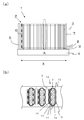
- FIG. 2 shows the cell stack device shown in FIG. 1, (a) a side view, and (b) a partially enlarged plan view of a part surrounded by a dotted line frame in (a).
- FIG. 2 shows the cell stack device shown in FIG. 1, (a) a side view, and (b) a partially enlarged plan view of a part surrounded by a dotted line frame in (a).
- FIG. 5 shows the cell stack device shown in FIG. 1
- FIG. 5 shows the cell stack device shown in FIG. 1
- FIG. 5 shows the cell stack device shown in FIG. 1
- FIG. 5 shows the cell stack device shown in FIG. 1
- FIG. 5 shows the cell stack device shown in FIG. 1
- FIG. 5 shows the cell stack device shown in FIG. 1
- FIG. 5 shows the cell stack device shown in FIG. 1
- FIG. 5 shows the cell stack device shown in FIG. 1
- FIG. 5 shows the cell stack device shown in FIG. 1
- FIG. 5 shows the cell stack device shown in FIG. 1
- FIG. 1 is an external perspective view showing an example of a cell stack device constituting the module of the present embodiment
- FIG. 2 shows the cell stack device shown in FIG. 1
- (a) is a plan view
- (b) is a plan view.
- It is sectional drawing which expands and shows a part of part enclosed with the dotted-line frame of (a).
- the description will be given mainly using the solid oxide fuel cell as the cell, and in the case of using the electrolytic cell capable of generating hydrogen as the cell, only the configuration different from the fuel cell This will be explained separately.
- the fuel cell 3 having the gas flow path 15 through which the fuel gas flows from one end to the other end is arranged in a row (in FIG. 1).
- the adjacent fuel cells 3 are electrically connected in series via the conductive members 6 and the lower ends of the fuel cells 3 are fixed to the manifold 4 with an insulating adhesive 9.
- Two cell stacks 2 are provided.
- water vapor is allowed to flow through the gas flow path 15 and the upper end of the cell is also connected to the manifold with an insulating adhesive such as a glass sealing material in order to recover hydrogen generated by the electrolytic reaction. It is fixed.
- the fuel cell 3 is a hollow flat plate type having a plurality of gas flow paths through which fuel gas flows in the longitudinal direction.
- the fuel electrode layer is formed on the surface of the support having the gas flow paths.
- 1 illustrates a solid oxide fuel cell 3 in which a solid electrolyte layer and an oxygen electrode layer are sequentially laminated. An oxygen-containing gas flows between the fuel cells 3.
- the configuration of the fuel cell 3 will be described later.
- the fuel cell 3 can be, for example, a flat plate type or a cylindrical type, and the shape of the cell stack device 1 can be changed as appropriate.
- a cell stack support member 7 (hereinafter sometimes abbreviated as stack support member 7) electrically connected to the fuel cell 3 located on the outermost side of the cell stack 2 via a conductive member 6 is provided. It has been.
- a protective cover may be provided outside the stack support member 7. The protective cover protects the stack support member 7 and the cell stack 2 against contact with a heat insulating material arranged around the cell stack 2 or impact from the outside.
- the stack support member 7 is connected to a conductive portion 8 that protrudes outside the cell stack 2.
- the cell stack apparatus 1 and 2 show the case where the cell stack apparatus 1 includes two cell stacks 2, the number can be changed as appropriate.
- the cell stack apparatus 1 includes only one cell stack 2. May be.
- the cell stack apparatus 1 can also include a reformer described later.
- the manifold 4 stores a fuel gas to be supplied to the fuel cell 3 and includes a gas case having an opening on the upper surface, and a frame body that fixes the fuel cell 3 inside and is fixed to the gas case. ing.
- One end of the fuel cell 3 (lower end in FIG. 2) is surrounded by a frame, and the outer periphery of the lower end of the fuel cell 3 is fixed by an insulating adhesive 9 filled inside the frame. Yes. That is, the cell stack 2 accommodates the plurality of fuel cells 3 side by side inside the frame and is bonded to the frame by the insulating adhesive 9.
- the insulating adhesive 9 can be made of a material such as glass and added with a predetermined filler in consideration of the thermal expansion coefficient.
- a gas flow pipe 8 through which fuel gas generated by a reformer described later flows is connected to the upper surface of the manifold 4.
- steam can be flowed in this gas distribution pipe 8.
- fuel gas or water vapor is supplied to the manifold 4 through the gas flow pipe 8 and is supplied from the manifold 4 to the gas flow path 15 provided inside the fuel cell 3.
- the fuel cell 3 has one flat surface of a columnar conductive support substrate 14 (hereinafter sometimes abbreviated as the support substrate 14) having a pair of opposed flat surfaces. It consists of columnar shape (hollow flat plate shape etc.) which laminates
- An interconnector 13 is provided on the other flat surface of the fuel cell 3, and a P-type semiconductor layer 16 is provided on the outer surface (upper surface) of the interconnector 13.
- the contact between the two becomes an ohmic contact, and it is possible to reduce the potential drop and effectively avoid the decrease in the current collecting performance.
- the conductive member 6 and the stack support member 7 are not shown.
- the support substrate also serves as a fuel-side electrode layer, and a cell can be formed by sequentially laminating a solid electrolyte layer and an air-side electrode layer on the surface thereof.
- porous conductive ceramics for example, ZrO 2 in which a rare earth element oxide is dissolved (referred to as stabilized zirconia, partially stabilized). And Ni and / or NiO.
- the solid electrolyte layer 11 has a function as an electrolyte that bridges electrons between the fuel-side electrode layer 10 and the air-side electrode layer 12, and at the same time, in order to prevent leakage of fuel gas and oxygen-containing gas It is required to have a gas barrier property, and is formed from ZrO 2 in which 3 to 15 mol% of a rare earth element oxide is dissolved. In addition, as long as it has the said characteristic, you may form using another material etc.
- the air-side electrode layer 12 is not particularly limited as long as it is generally used.
- the air-side electrode layer 12 can be formed of a conductive ceramic made of a so-called ABO 3 type perovskite oxide.
- the air-side electrode layer 12 needs to have gas permeability, and the open porosity is preferably 20% or more, particularly preferably in the range of 30 to 50%.
- the support substrate 14 is required to be gas permeable in order to permeate the fuel gas to the fuel-side electrode layer 10 and to be conductive in order to conduct through the interconnector 13. Accordingly, conductive ceramics or cermets can be used as the support substrate 14.
- the support substrate 14 is formed from an iron group metal component and a specific rare earth oxide. Preferably formed.
- the columnar (hollow flat plate) support substrate 14 is a plate-like piece elongated in the standing direction (Y direction shown in FIG. 1). It has circular side surfaces.
- the support substrate 14 preferably has an open porosity of 30% or more, particularly 35 to 50% in order to have gas permeability, and its conductivity is 300 S / cm or more, particularly 440S. / Cm or more is preferable.
- the shape of the support substrate 14 should just be columnar, and may be cylindrical.
- An example of the P-type semiconductor layer 16 is a layer made of a transition metal perovskite oxide. Specifically, a material having higher electronic conductivity than the material constituting the interconnector 13, for example, LaMnO 3 -based oxide, LaFeO 3 -based oxide, LaCoO 3 -based oxide in which Mn, Fe, Co, etc. exist at the B site. P-type semiconductor ceramics made of at least one oxide or the like can be used. In general, the thickness of the P-type semiconductor layer 16 is preferably in the range of 30 to 100 ⁇ m.
- lanthanum chromite-based perovskite oxide LaCrO 3 -based oxide
- LaSrTiO 3 -based oxide lanthanum strontium titanium-based perovskite-type oxide
- the interconnector 13 must be dense to prevent leakage of the fuel gas flowing through the gas flow path 11 formed in the support substrate 14 and the oxygen-containing gas flowing outside the support substrate 14, It is preferable to have a relative density of 93% or more, particularly 95% or more.
- the conductive member and the cell stack support member 7 that are interposed to electrically connect the fuel cells 3 are a surface required for a member made of an elastic metal or alloy or a felt made of metal fiber or alloy fiber. It can comprise from the member which processed.
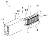
- FIG. 3 is an external perspective view showing an example of a module (fuel cell module) including the cell stack device 18 of the present embodiment
- FIG. 4 is a cross-sectional view of FIG.
- the sectional view means a sectional view orthogonal to the arrangement direction of the fuel cells 3.
- the cell stack device 18 of the present embodiment is stored inside the storage container 19.
- a reformer 20 for generating fuel gas to be supplied to the fuel cell 3 is disposed above the cell stack device 18.
- the reformer 20 preferably has a structure capable of performing steam reforming, which is a reforming reaction with high reforming efficiency.
- the reformer 20 has a vaporization section 21 for vaporizing water, and raw fuel is used as fuel gas. And a reforming unit 22 in which a reforming catalyst (not shown) for reforming is disposed.
- FIG. 3 shows a state where a part (front and rear surfaces) of the storage container 19 is removed and the cell stack device 18 stored inside is taken out rearward.
- the cell stack device 18 can be slid and stored in the storage container 19.
- an oxygen-containing gas supply member 24 as a first gas supply unit is disposed.
- the storage container 19 constituting the module 17 has a double structure having an inner wall 25 and an outer wall 26, and an outer frame of the storage container 19 is formed by the outer wall 26.
- a storage chamber 27 for storing the cell stack device 18 is formed.
- the storage container 19 includes an oxygen-containing gas introduction portion 28 that is a first gas introduction portion for introducing an oxygen-containing gas introduced from the outside into the storage chamber 27.
- the oxygen-containing gas introduced into the oxygen-containing gas introduction part 28 is provided by the inner wall 25 and the outer wall 26 on the side of the storage chamber 27, and is an oxygen-containing gas that is a first gas circulation part connected to the oxygen-containing gas introduction part 28.
- the distribution part 29 flows upward. Subsequently, the gas flows through an oxygen-containing gas distribution section 30 that is a first gas distribution section provided with an inner wall 25 and an outer wall 26 above the storage chamber 27 and connected to the oxygen-containing gas circulation section 29.
- the oxygen-containing gas distribution unit 30 includes an oxygen-containing gas inlet (not shown) through which oxygen-containing gas flows into the upper end side and a flange portion 31, and a lower end portion of the fuel cell 3 at the lower end portion.
- a heat insulating member 33 is disposed between the flange portion 31 and the inner wall 25.
- the oxygen-containing gas supply member 24 is arranged so as to be positioned between two cell stacks 2 juxtaposed inside the storage container 19, but according to the number of cell stacks 2, It can arrange
- two oxygen-containing gas supply members 24 can be provided so as to sandwich the cell stack 2 from both side surfaces.
- the temperature in the module 17 is maintained at a high temperature so that the heat in the module 17 is extremely dissipated and the temperature of the fuel cell 3 (cell stack 2) is lowered and the power generation amount is not reduced.
- a heat insulating member 33 is appropriately provided.
- the heat insulating member 33 is preferably disposed in the vicinity of the cell stack 2.
- the heat insulating member 33 is disposed on the side of the cell stack 2 along the arrangement direction of the fuel cells 3, and the fuel cell on the side of the cell stack 2. It is preferable to arrange the heat insulating member 33 having a width equal to or greater than the width along the three arrangement directions. In addition, it is preferable to arrange the heat insulating members 33 on both side surfaces of the cell stack 2. Thereby, it can suppress effectively that the temperature of the cell stack 2 falls.
- the oxygen-containing gas introduced from the oxygen-containing gas supply member 24 can be prevented from being discharged from the side surface side of the cell stack 2, and the flow of the oxygen-containing gas between the fuel cells 3 constituting the cell stack 2. Can be promoted.
- the flow of the oxygen-containing gas supplied to the fuel cell 3 is adjusted, and the longitudinal direction of the cell stack 2 and the arrangement direction of the fuel cell 3 are adjusted.
- An opening 34 is provided to reduce the temperature distribution at.
- An exhaust gas inner wall 35 is provided inside the inner wall 25 along the arrangement direction of the fuel cells 3, and the space between the inner wall 25 and the exhaust gas inner wall 35 on the side of the storage chamber 27 is the storage chamber.
- 27 is an exhaust gas circulation part 36 in which the exhaust gas in 27 flows downward from above.
- an exhaust gas collecting unit 37 connected to the exhaust gas circulation unit 36 is provided below the storage chamber 27 and above the oxygen-containing gas introduction unit 28.
- the exhaust gas collecting unit 37 communicates with an exhaust hole 38 provided at the bottom of the storage container 19.
- a heat insulating member 33 is also provided on the exhaust gas inner wall 35 on the cell stack 2 side.
- the exhaust gas generated with the operation of the module 17 flows through the exhaust gas circulation section 36 and the exhaust gas collection section 37 and is then exhausted from the exhaust hole 38.
- the exhaust hole 38 may be formed by cutting out a part of the bottom of the storage container 19 or may be formed by providing a tubular member.
- thermocouple 39 for measuring the temperature in the vicinity of the cell stack 2 is provided inside the oxygen-containing gas supply member 24, and the temperature measuring unit 40 is the central portion in the longitudinal direction of the fuel cell 3 and the fuel cell. 3 are arranged so as to be located at the center in the arrangement direction.
- the fuel gas and the oxygen-containing gas that have not been used for power generation discharged from the gas flow path 15 in the fuel cell 3 are transferred to the upper end of the fuel cell 3,
- the temperature of the fuel cell 3 can be raised and maintained by burning between the two.
- the reformer 20 disposed above the fuel cell 3 (cell stack 2) can be warmed, and the reformer 20 can efficiently perform the reforming reaction.
- the temperature in the module 17 becomes about 500 to 800 ° C. with the combustion and power generation of the fuel cell 3.
- each flow path through which the oxygen-containing gas flows has a structure in which the oxygen-containing gas flows efficiently. That is, in the module 17 shown in FIG. 4, it is introduced into the oxygen-containing gas introduction section 28, flows on both sides of the storage chamber 27, and is introduced into the oxygen-containing gas supply member 24 through the oxygen-containing gas distribution chamber 30. It is preferable to have a structure in which the oxygen-containing gas flows efficiently and is evenly distributed.
- the width W1 of the oxygen-containing gas introduction portion 28 when the width W1 of the oxygen-containing gas introduction portion 28 is first compared with the width W2 of the oxygen-containing gas circulation portion 29 in the cross section orthogonal to the arrangement direction of the fuel cells 3. Moreover, the width W2 of the oxygen-containing gas flow part 29 is narrower than the width W1 of the oxygen-containing gas introduction part 28. Thereby, the oxygen-containing gas introduced into the oxygen-containing gas introduction unit 28 can be efficiently flowed to the oxygen-containing gas circulation unit 29.
- the width W2 of the oxygen-containing gas circulation part 29 is preferably set to a width that does not block even if the inner wall 25 and the outer wall 26 are deformed due to deterioration with time of the storage container 19, and the width W1 of the oxygen-containing gas introduction part 28 is In comparison, it can be in the range of 1/3 to 1/30.
- the width W1 of the oxygen-containing gas introduction part 28 is not particularly limited, but if it is too large, there is a problem that the module becomes large.
- the width W2 of the oxygen-containing gas circulation part 29 located on each side of the storage chamber 27 is within a range of ⁇ 10% when compared with each other.
- the oxygen-containing gas introduced into the oxygen-containing gas introduction portion 28 flows in substantially the same amount to the respective sides of the storage chamber 27.
- the width W4 of the oxygen-containing gas supply member 24 is equal to the width W4 of the oxygen-containing gas supply member 24. It is narrower than the width W3. Thereby, the oxygen-containing gas introduced into the oxygen-containing gas distribution unit 30 can be efficiently flowed to the oxygen-containing gas supply member 24.
- the width W4 of the oxygen-containing gas supply member 24 is preferably set to a width that does not block even when the oxygen-containing gas supply member 24 is deformed due to deterioration over time, and is compared with the width W3 of the oxygen-containing gas distribution unit 30. , 1/2 to 1/30.
- the width W3 of the oxygen-containing gas distribution unit 30 is not particularly limited, but if it is too large, there is a problem that the module becomes large. In determining the width, it is preferable to consider the pressure loss of the oxygen-containing gas outlet 32.
- the oxygen-containing gas introduction part 28, the oxygen-containing gas circulation part 29, and the oxygen-containing gas distribution part 30 preferably have the same depth (the arrangement direction X of the fuel cells 3). Further, the depth of the oxygen-containing gas supply member 24 may be shorter than that of the oxygen-containing gas distributor 30, but may be set within a range in which the above effect can be obtained.
- exhaust gas such as a fuel gas and an oxygen-containing gas that have not been used for power generation, a combustion gas generated by burning the fuel gas, and the like are generated.
- This exhaust gas is also efficiently discharged outside the storage container 19, and as a result, the oxygen-containing gas is efficiently supplied to the fuel cell 3.
- the width W5 of the exhaust gas circulation part 36 provided on the side of the storage chamber 27 and the width W6 of the exhaust gas collection part 37 provided below the storage chamber 27 are compared.
- the width W5 of the exhaust gas circulation part 36 is narrower than the width W6 of the exhaust gas collection part 37.
- the width W5 of the exhaust gas circulation section 36 is preferably set to a width that does not block even if the exhaust gas circulation section 36 is deformed due to deterioration with time. Compared with the width W6 of the exhaust gas collection section 37, 1/3 to 1 / 30 range.
- the width W6 of the exhaust gas collecting unit 36 is not particularly limited, but if it is too large, there is a problem that the module becomes large.
- the width W5 of the exhaust gas circulation portion 36 located on each side of the storage chamber 27 is within a range of ⁇ 10% when compared with each other. Thereby, almost the same amount of exhaust gas in the storage chamber 27 flows to each side of the storage chamber 27.
- the length of the depth (arrangement direction X of the fuel cells 3) of the exhaust gas circulation part 36 and the exhaust gas collection part 37 is approximately the same.
- an electrolytic module in which an electrolytic cell stack device in which electrolytic cells capable of generating hydrogen by applying steam and voltage as cells are arranged in the storage chamber 27 of the module 17 is stored.
- oxygen is discharged from the electrolysis cell as a by-product when hydrogen is generated from water vapor.
- high-concentration oxygen is present in the storage chamber 27, there is a risk of ignition due to some impact or the like, and the electrolytic cell itself may deteriorate due to oxidation.
- an electrolytic module including an electrolytic cell stack device can be a module with good efficiency (electrolytic efficiency).
- FIG. 5 is a cross-sectional view showing another example of the module of the present embodiment.
- the module 41 shown in FIG. 5 includes four cell stack devices 43 in the storage chamber 42, and an exhaust gas circulation member 44 is provided between the cell stack devices 43. 6 in that one reformer 45 is provided above the four cell stacks as shown in FIG.
- the exhaust gas circulation section positioned on the side of the storage chamber 42 from the fuel cell 3 in the cell stack device 43 positioned on the center portion side.
- the distance to 36 becomes long, and it may be difficult to efficiently discharge the exhaust gas discharged from the fuel cell 3 in the cell stack device 43 located on the center side.
- the fuel cell device configured to burn the fuel gas not used for power generation on the upper end side of the fuel cell 3 and maintain the temperature of the fuel cell 3 at a high temperature by the combustion heat
- the temperature of the fuel cell does not increase or cannot be maintained at a high temperature, and as a result, the power generation amount of the fuel cell 3 (cell stack device 43) may decrease. There is.
- a member 44 is provided.
- This exhaust gas circulation member 44 is formed of a cylindrical container, and has an exhaust gas inlet 46 communicating with the storage chamber 42 on both sides at the upper end, and a discharge port 47 as a lower end is provided below the storage chamber 42. It communicates with the exhaust gas collecting part 37.
- FIG. 5 although the example which formed the waste gas distribution
- either the exhaust gas circulation part 36 or the exhaust gas circulation member 44 is arranged on the side of each cell stack device 43, and the exhaust gas that has not been used for power generation constitutes each cell stack device 43.
- the gas flows efficiently to the exhaust gas circulation part 36 or the exhaust gas circulation member 44 on the side close to the cell stack 2.
- the module 41 with improved power generation can be obtained.
- the width W7 of the exhaust gas circulation member 44 is compared with the width W6 of the exhaust gas collection part 37 provided below the storage chamber 42, the width W7 of the exhaust gas circulation member 44 is equal to the width W6 of the exhaust gas collection part 37. It is narrower than. As a result, the exhaust gas flowing through the exhaust gas circulation member 44 is efficiently mixed in the exhaust gas collecting unit 37 and discarded to the outside through the exhaust hole 38.
- the width W7 of the exhaust gas circulation member 44 can be set to a range of 1/3 to 1/30 compared with the width W6 of the exhaust gas collection unit 37.
- the width W6 of the exhaust gas collecting unit 37 is not particularly limited, but if it is too large, there is a problem that the module becomes large.
- each exhaust gas circulation member 44 is preferably within a range of ⁇ 10% when compared with each other. As a result, substantially the same amount of exhaust gas flows through each exhaust gas circulation member 44.
- the exhaust gas circulation member 44 is constituted by a cylindrical container, it is preferable that the exhaust gas circulation member 44 and the exhaust gas collection part 37 have the same depth (the arrangement direction X of the fuel cells 3). .
- FIG. 6 is a perspective view showing the reformer housed in the module shown in FIG. 5 and FIG. 7 shows a configuration in which the reformer shown in FIG. 6 is provided above the cell stack device of this embodiment. It is a side view which shows an example.
- the reformer 45 vaporizes water to produce steam, and steam is generated from the raw fuel using steam generated in the vaporizer 45a. And a reforming portion 45b for quality improvement.
- the vaporizer 45a includes a vaporizer forward path 45a1 in which water vapor flows from one end to the other end, and a vaporizer return path 45a2 in which water vapor flows from the other end to the one end.
- the vaporization part forward path 45a1 includes a cylindrical part 48a that protrudes from one end along the vaporization part forward path 45a1, and a water supply part 48b that is connected to the one end part and supplies water to the cylindrical part 48a. I have.
- the cylindrical portion 48a is provided so as to protrude inward from the tube constituting the vaporizing portion, and a water supply pipe that is a water supply portion 48b is connected to the cylindrical portion 48a.
- a configuration may be employed in which a certain water supply pipe is inserted from the outside into the inside, and a part of the water supply pipe becomes the cylindrical portion 48a.
- description will be made using a configuration in which the water supply pipe 46 is inserted from the outside into the inside.
- the reforming unit 45b is a reforming unit forward path 45b1 in which reformed gas generated by reforming the raw fuel supplied from the raw fuel supply pipe 23 which is a raw fuel supply unit flows from one end side to the other end side. And a reforming part return path 45b2 in which the reformed gas flows from the other end side to the one end side.
- a reformed gas outlet pipe 49 for leading the reformed gas is connected to the reforming part return path 45b2. ing.
- the water supply pipe 48, the raw fuel supply pipe 23 and the reformed gas outlet pipe 49 are connected to one side of the reformer 45.
- the other end side of the vaporization section forward path 45a1 and the other end side of the vaporization section return path 45a2 are connected by a connection path (hereinafter referred to as a vaporization section connection path) 45c1, and one end of the vaporization section return path 45a2.
- a connection path hereinafter referred to as a vaporization section connection path
- the one end side of the reforming section forward path 45b1 are connected by a coupling path (hereinafter referred to as a vaporization reforming section coupling path) 45c2, and the other end side of the reforming section outbound path 45b1 and the other end side of the reforming section return path 45b2.
- a connecting path (hereinafter referred to as a reforming section connecting path) 45c3
- the vaporizing section forward path 45a1, the vaporizing section return path 45a2, the reforming section outbound path 45b1, and the reforming section return path 45b2 are connected to the side. They are juxtaposed so that they face each other.
- the water supplied to the vaporization unit forward path 45a1 becomes water vapor, and sequentially flows through the vaporization unit connection path 45c1, the vaporization unit return path 45a2, the vaporization reforming unit connection path 45c2, and the reforming unit forward path 45b1.
- the raw fuel is supplied from the raw fuel supply pipe 23, which is the raw fuel supply unit 23b, and is mixed with steam in the vaporization reforming unit connection path 45c2, and the reforming unit forward path 45b1 and the reforming unit are connected.
- the reformed gas (fuel gas) containing hydrogen is reformed while flowing through the path 45c3 and the reforming part return path 45b2, and is led out from the reformed gas outlet pipe 49.
- the vaporization section forward path 45a1, the vaporization section return path 45a2, the reforming section forward path 45b1, the reforming section return path 45b2, the vaporization section connection path 45c1, the vaporization reforming section connection path 45c2, and the reforming section connection path 45c3 have a rectangular cross section. It consists of a tube.
- partition plates 45a11 and 45a21 are respectively provided in the vaporization section forward path 45a1 and the vaporization section return path 45a2, and a space between these partition plates 45a11 and 45a21 serves as a vaporization chamber, and a tip end portion (tubular shape) of the water supply pipe 48 is provided. Part) is located on the upstream side of the partition plate 45a11 and supplies water to a position in front of the vaporization chamber. Ceramic balls are accommodated in the vaporizing chamber to promote vaporization, and the partition plates 45a11 and 45a21 are formed so that water vapor passes but ceramic balls do not pass.
- the arrangement of the partition plates 45a11 and 45a21 can be appropriately changed according to the structure of the reformer, the structure of the cell stack described later, and the like.
- partition plates 45b11 and 45b21 are also arranged in the reforming unit forward path 45b1 and the reforming unit return path 45b2, respectively, and the reforming unit forward path 45b1, the reforming unit connection path 1c3, the reforming part located between the partition plates 45b11 and 45b21,
- the mass part return path 45b2 serves as a reforming chamber, and a reforming catalyst is accommodated in the reforming chamber.
- the partition plates 45b11 and 45b21 are configured so that gas such as water vapor, raw fuel, and reformed gas can pass but the reforming catalyst cannot pass.
- the arrangement of the partition plates 45b11 and 45b21 can be appropriately changed according to the structure of the reformer, the structure of the cell stack described later, and the like.
- a raw fuel supply pipe 23 which is a raw fuel supply part 23b for supplying raw fuel, to a vaporization reforming part connection path 45c2 between the vaporization part 45a and the reforming part 45b. It is connected.
- the raw fuel supply pipe 23 is connected to the vaporization reforming part connection path 45c2 on the downstream side of the vaporization part forward path 45a1 to which the water supply pipe 48 is connected.
- the point where the fuel is supplied and the point where the raw fuel is supplied are via a space between the tube constituting the vaporization part forward path 45a1 and the pipe constituting the vaporization part return path 45a2, and the flow direction of water vapor
- the length in the flow direction is long.
- water supply pipe 48 and the raw fuel supply pipe 23 may have a double pipe structure, and each may be connected to the vaporization section forward path 45a1.
- the reformed gas (fuel gas) generated by the reformer 45 is supplied to the two manifolds 4 by the reformed gas outlet pipe 49, and the fuel battery cell 3 is passed through the manifold 4. Is supplied to a gas flow path provided in the interior.
- the reformed gas generated by the reformer 45 is supplied from the reformed gas outlet pipe 49 to the two manifolds 4 via the distributor 50 as shown in FIG.
- the reformed gas outlet pipe 49 has a U-shaped first reformed gas outlet pipe 49a from the reformer 45 to the distributor 50 and a second modified gas extending from the distributor 50 to the two lower manifolds 4 respectively.
- a quality gas outlet pipe 49b a quality gas outlet pipe 49b.
- the lengths of the first reformed gas outlet pipe 49a and the second reformed gas outlet pipe 49b are set to the same length (pressure loss) so as to supply the reformed gas to the manifold 4 evenly.
- each of the vaporization section forward path 45a1, the vaporization section return path 45a2, the reforming section forward path 45b1, and the reforming section return path 45b2 is arranged above the cell stack in correspondence with one cell stack. . Thereby, each of the vaporization part going path 45a1, the vaporization part return path 45a2, the reforming part going path 45b1, and the reforming part return path 45b2 can be efficiently heated.
- FIG. 8 is a cross-sectional view showing still another example of the fuel cell module of the present embodiment.
- the module 50 shown in FIG. 8 does not have the exhaust gas circulation member 44 disposed between the cell stack devices, and the fuel cell 3 is located above the storage chamber 42.
- An exhaust gas recovery unit 51 that recovers exhaust gas discharged from the exhaust gas is provided, and the exhaust gas recovery unit 51 and the exhaust gas circulation unit 36 are connected to each other.
- the module 41 shown in FIG. 5 has an advantage that the exhaust gas discharged from the fuel cell 3 can be efficiently discharged to the outside, but the exhaust gas flowing through the exhaust gas circulation member 44 is an oxygen-containing gas supplied from the outside. Therefore, there is room for improvement in terms of heat exchange between the oxygen-containing gas supplied from the outside and the exhaust gas discharged from the fuel cell 3.
- an exhaust gas recovery part 51 that recovers the exhaust gas discharged from the fuel cell 3 is provided above the storage chamber 42, and the exhaust gas recovery part 51 and the exhaust gas circulation part 36 are connected to each other. Therefore, the entire amount of exhaust gas discharged from the fuel cell 3 can exchange heat with the oxygen-containing gas supplied from the outside. As a result, the oxygen-containing gas whose temperature has risen can be supplied to the fuel cell 3 and the power generation efficiency can be improved.
- the exhaust gas recovered in the exhaust gas recovery unit 51 is configured to efficiently flow into the exhaust gas circulation unit 36. Therefore, in the module 50 of the present embodiment, when the width W5 of the exhaust gas circulation part 36 provided on the side of the storage chamber 42 is compared with the width W8 of the exhaust gas recovery part 51, the exhaust gas circulation part 36 The width W5 is narrower than the width W8 of the exhaust gas recovery unit 51. As a result, the exhaust gas recovered in the exhaust gas recovery part 51 efficiently flows to the exhaust gas circulation part 36 on each side of the storage chamber 42. Thereby, heat exchange with the oxygen-containing gas is improved, and power generation efficiency can be improved.
- the width W5 of the exhaust gas circulation part 36 can be set to a range of 1/3 to 1/30 compared with the width W8 of the exhaust gas recovery part 51.
- the width W8 of the exhaust gas recovery unit 51 is not particularly limited, but if it is too large, there is a problem that the module becomes large.
- the exhaust gas circulation part 36 and the exhaust gas recovery part 51 preferably have the same depth (the arrangement direction X of the fuel cells 3).
- a recovery hole 52 connected to the storage chamber 42 is provided on the bottom surface of the exhaust gas recovery unit 51. As a result, the exhaust gas discharged into the storage chamber 42 flows into the exhaust gas recovery part 51 through the recovery hole 52.
- FIG. 9 is a plan view showing a part of the bottom surface of the exhaust gas recovery unit 51.
- the reformer 45 is indicated by a broken line so that the positional relationship with the reformer 45 can be understood.
- the recovery holes 52 provided on the bottom surface of the exhaust gas recovery part 51 preferably all the recovery holes 52 are provided facing the reformer 45.
- the reforming efficiency can be improved by heating the reformer 45 with the combustion heat generated by burning the exhaust gas discharged from the fuel cell 3. Therefore, it is preferable that the exhaust gas (combustion exhaust gas) discharged from the fuel cell 3 flows to the exhaust gas recovery unit 51 after flowing around the reformer 45.
- FIG. 9 shows an example in which all the recovery holes 52 are provided facing the reformer 45. Accordingly, the exhaust gas (combustion exhaust gas) discharged from the fuel battery cell 3 efficiently flows around the reformer 45 and then flows to the exhaust gas recovery unit 51. Thereby, the temperature of the reformer 45 can be improved efficiently, and the reforming efficiency can be improved.
- FIG. 9 an example in which the same number of recovery holes 51 are provided facing each of the vaporization section forward path 45 a 1, the vaporization section return path 45 a 2, the reforming section forward path 45 b 1, and the reforming section return path 45 b 2 in the reformer 45.
- the number of the recovery holes 51 is not limited to this.
- the temperature of the vaporization section forward path 45a1 is lowered due to an endothermic reaction accompanying the vaporization of water, and as a result, the temperature of the cell stack 2 located therebelow may also be lowered.
- the number of the recovery holes 51 facing the vaporization part forward path 45a1 may be increased.
- recovery holes 51 can be set suitably.
- FIG. 10 is an exploded perspective view showing an example of a fuel cell device in which any one of the modules 17, 41 and 50 and an auxiliary machine for operating each module are housed in the outer case. In FIG. 10, a part of the configuration is omitted.
- a fuel cell device 53 shown in FIG. 10 divides the interior of an outer case composed of a column 54 and an outer plate 55 by a partition plate 56, and the upper side serves as a module storage chamber 57 for storing the above-described modules.
- the lower side is configured as an auxiliary machine storage chamber 58 for storing auxiliary machines for operating each module. Auxiliaries stored in the auxiliary machine storage chamber 58 are not shown.
- the partition plate 56 is provided with an air circulation port 59 for flowing the air in the auxiliary machine storage chamber 58 toward the module storage chamber 57, and a part of the exterior plate 57 constituting the module storage chamber 57 An exhaust port 60 for exhausting air in the module storage chamber 57 is provided.
- the mode including the cell stack device in which one reformer 45 is disposed above the four cell stacks 2 has been described.
- a cell stack apparatus in which one reformer is disposed above the cell stack 2 may be used, and a cell stack apparatus in which one reformer is disposed above five or more cell stacks may be used.
- the shape of the reformer may be changed as appropriate.
- one cell stack may be arranged in one manifold, and three or more in one manifold.
- the cell stack may be arranged.
- the fuel cell 3 called a so-called vertical stripe type has been described.
- a horizontal stripe type fuel cell in which a plurality of power generation element portions generally called a horizontal stripe type are provided on a support may be used. it can.
- the fuel cell 3 the fuel cell stack device 1, the modules 17, 41, 50 and the fuel cell device 53 have been described in the above embodiment, water vapor and water are applied to the cells to electrolyze water vapor (water).
- the present invention can also be applied to an electrolysis cell (SOEC) that generates hydrogen and oxygen (O 2 ), an electrolysis cell stack device including the electrolysis cell, an electrolysis module, and an electrolysis device.
- SOEC electrolysis cell
- O 2 hydrogen and oxygen
Landscapes
- Chemical & Material Sciences (AREA)
- Engineering & Computer Science (AREA)
- Chemical Kinetics & Catalysis (AREA)
- Electrochemistry (AREA)
- Materials Engineering (AREA)
- Metallurgy (AREA)
- Organic Chemistry (AREA)
- Life Sciences & Earth Sciences (AREA)
- Manufacturing & Machinery (AREA)
- Sustainable Development (AREA)
- Sustainable Energy (AREA)
- General Chemical & Material Sciences (AREA)
- Inorganic Chemistry (AREA)
- Fuel Cell (AREA)
- Electrolytic Production Of Non-Metals, Compounds, Apparatuses Therefor (AREA)
Abstract
Description
2:セルスタック
3:セル
17、41、50:モジュール
19:収納容器
20、45:改質器
24:酸素含有ガス供給部
27、42:収納室
28:酸素含有ガス導入部
29:酸素含有ガス流通部
30:酸素含有ガス分配部
36:排ガス流通部
37:排ガス収集部
44:排ガス流通部材
51:排ガス回収部
52:回収孔
53:燃料電池装置
Claims (6)
- 収納容器内に、複数個のセルを配列してなるセルスタックを備えるセルスタック装置を収納してなり、
前記収納容器は、
前記セルスタック装置を収納する収納室と、該収納室の下方に設けられた、前記収納室内に供給する第1のガスを導入するための第1ガス導入部と、前記収納室の側方に設けられた、前記第1ガス導入部につながる第1ガス流通部とを備えるとともに、
前記セルの配列方向に直交する断面において、前記第1ガス流通部の幅が、前記第1ガス導入部の幅よりも狭い
モジュール。 - 前記収納室の上方に、前記第1ガス流通部につながって前記第1ガスを分配するための第1ガス分配部と、該第1ガス分配部につながって前記収納室内に前記第1ガスを供給するための第1ガス供給部とを備え、
前記セルの配列方向に直交する断面において、前記第1ガス供給部の幅が、前記第1ガス分配部の幅よりも狭い請求項1に記載のモジュール。 - 前記収納室の側方に位置した、前記セルから排出される排ガスが流通する排ガス流通部と、前記収納室の下方に位置した、前記排ガス流通部につながる排ガス収集部とを備え、
前記セルの配列方向に直交する断面において、前記排ガス流通部の幅が、前記排ガス収集部の幅よりも狭い請求項1または請求項2に記載のモジュール。 - 前記収納室の上方に位置した、前記セルから排出される排ガスを回収するとともに前記排ガス流通部につながる排ガス回収部を備えるとともに、
前記セルの配列方向に直交する断面において、前記排ガス流通部の幅が、前記排ガス回収部の幅よりも狭い請求項3に記載のモジュール。 - 前記セルが燃料電池セルであり、前記第1のガスが酸素含有ガスであり、
前記セルスタックの上方に、前記セルに供給する燃料ガスを生成するための改質器を備え、
前記排ガス回収部の底面に、前記セルから排出される排ガスを回収するための回収孔を備えるとともに、該回収孔の少なくとも一部が前記改質器に対向して設けられている請求項4に記載の燃料電池モジュール。 - 請求項1乃至請求項5のうちいずれかに記載のモジュールと、該モジュールを作動させるための補機と、前記モジュールおよび前記補機を収容する外装ケースとを備えるモジュール収容装置。
Priority Applications (4)
| Application Number | Priority Date | Filing Date | Title |
|---|---|---|---|
| JP2016566310A JP6259128B2 (ja) | 2014-12-24 | 2015-12-18 | モジュールおよびモジュール収容装置 |
| CN201580069467.4A CN107112552B (zh) | 2014-12-24 | 2015-12-18 | 模块以及模块收容装置 |
| EP15872929.3A EP3240074B1 (en) | 2014-12-24 | 2015-12-18 | Module and module accommodation device |
| US15/539,176 US10724144B2 (en) | 2014-12-24 | 2015-12-18 | Module and module accomodation device |
Applications Claiming Priority (2)
| Application Number | Priority Date | Filing Date | Title |
|---|---|---|---|
| JP2014260674 | 2014-12-24 | ||
| JP2014-260674 | 2014-12-24 |
Publications (1)
| Publication Number | Publication Date |
|---|---|
| WO2016104361A1 true WO2016104361A1 (ja) | 2016-06-30 |
Family
ID=56150381
Family Applications (1)
| Application Number | Title | Priority Date | Filing Date |
|---|---|---|---|
| PCT/JP2015/085484 Ceased WO2016104361A1 (ja) | 2014-12-24 | 2015-12-18 | モジュールおよびモジュール収容装置 |
Country Status (5)
| Country | Link |
|---|---|
| US (1) | US10724144B2 (ja) |
| EP (1) | EP3240074B1 (ja) |
| JP (1) | JP6259128B2 (ja) |
| CN (1) | CN107112552B (ja) |
| WO (1) | WO2016104361A1 (ja) |
Cited By (3)
| Publication number | Priority date | Publication date | Assignee | Title |
|---|---|---|---|---|
| WO2017038782A1 (ja) * | 2015-08-31 | 2017-03-09 | 京セラ株式会社 | 燃料電池モジュールおよび燃料電池装置 |
| EP3331080A1 (en) * | 2016-12-02 | 2018-06-06 | Toto Ltd. | Fuel cell stack device and fuel cell device |
| JP2018092908A (ja) * | 2016-12-02 | 2018-06-14 | Toto株式会社 | 燃料電池モジュール |
Families Citing this family (1)
| Publication number | Priority date | Publication date | Assignee | Title |
|---|---|---|---|---|
| FR3130356B1 (fr) * | 2021-12-14 | 2025-06-20 | Bulane | Installation comprenant un appareil à combustion et un électrolyseur. |
Citations (5)
| Publication number | Priority date | Publication date | Assignee | Title |
|---|---|---|---|---|
| WO2009119615A1 (ja) * | 2008-03-26 | 2009-10-01 | 京セラ株式会社 | 燃料電池モジュールおよび燃料電池装置 |
| JP2011249160A (ja) * | 2010-05-27 | 2011-12-08 | Kyocera Corp | 燃料電池モジュールおよび燃料電池装置 |
| JP2013030359A (ja) * | 2011-07-28 | 2013-02-07 | Kyocera Corp | 燃料電池装置 |
| JP2014026863A (ja) * | 2012-07-27 | 2014-02-06 | Kyocera Corp | セルスタック装置、燃料電池モジュールおよび燃料電池装置 |
| WO2014189135A1 (ja) * | 2013-05-23 | 2014-11-27 | 京セラ株式会社 | 燃料電池モジュールおよび燃料電池装置 |
Family Cites Families (7)
| Publication number | Priority date | Publication date | Assignee | Title |
|---|---|---|---|---|
| JP4943037B2 (ja) | 2005-07-27 | 2012-05-30 | 京セラ株式会社 | 燃料電池モジュール |
| CN100592562C (zh) * | 2005-07-27 | 2010-02-24 | 京瓷株式会社 | 燃料电池模块 |
| JP5224849B2 (ja) | 2008-02-26 | 2013-07-03 | 京セラ株式会社 | 燃料電池モジュールおよび燃料電池装置 |
| CN101978543B (zh) * | 2008-03-26 | 2013-06-12 | 京瓷株式会社 | 改性器、燃料电池堆装置及燃料电池模块和燃料电池装置 |
| JP5065367B2 (ja) * | 2009-12-15 | 2012-10-31 | トヨタ自動車株式会社 | 燃料電池モジュール |
| JP6109484B2 (ja) | 2012-03-12 | 2017-04-05 | アイシン精機株式会社 | 燃料電池装置 |
| JP6139209B2 (ja) * | 2013-03-27 | 2017-05-31 | 京セラ株式会社 | 燃料電池モジュール |
-
2015
- 2015-12-18 CN CN201580069467.4A patent/CN107112552B/zh not_active Expired - Fee Related
- 2015-12-18 US US15/539,176 patent/US10724144B2/en active Active
- 2015-12-18 EP EP15872929.3A patent/EP3240074B1/en active Active
- 2015-12-18 WO PCT/JP2015/085484 patent/WO2016104361A1/ja not_active Ceased
- 2015-12-18 JP JP2016566310A patent/JP6259128B2/ja active Active
Patent Citations (5)
| Publication number | Priority date | Publication date | Assignee | Title |
|---|---|---|---|---|
| WO2009119615A1 (ja) * | 2008-03-26 | 2009-10-01 | 京セラ株式会社 | 燃料電池モジュールおよび燃料電池装置 |
| JP2011249160A (ja) * | 2010-05-27 | 2011-12-08 | Kyocera Corp | 燃料電池モジュールおよび燃料電池装置 |
| JP2013030359A (ja) * | 2011-07-28 | 2013-02-07 | Kyocera Corp | 燃料電池装置 |
| JP2014026863A (ja) * | 2012-07-27 | 2014-02-06 | Kyocera Corp | セルスタック装置、燃料電池モジュールおよび燃料電池装置 |
| WO2014189135A1 (ja) * | 2013-05-23 | 2014-11-27 | 京セラ株式会社 | 燃料電池モジュールおよび燃料電池装置 |
Cited By (8)
| Publication number | Priority date | Publication date | Assignee | Title |
|---|---|---|---|---|
| WO2017038782A1 (ja) * | 2015-08-31 | 2017-03-09 | 京セラ株式会社 | 燃料電池モジュールおよび燃料電池装置 |
| US10886545B2 (en) | 2015-08-31 | 2021-01-05 | Kyocera Corporation | Fuel cell module and fuel cell apparatus |
| EP3331080A1 (en) * | 2016-12-02 | 2018-06-06 | Toto Ltd. | Fuel cell stack device and fuel cell device |
| CN108155405A (zh) * | 2016-12-02 | 2018-06-12 | Toto株式会社 | 燃料电池电堆装置以及燃料电池装置 |
| JP2018092908A (ja) * | 2016-12-02 | 2018-06-14 | Toto株式会社 | 燃料電池モジュール |
| JP2018092905A (ja) * | 2016-12-02 | 2018-06-14 | Toto株式会社 | 燃料電池セルスタック装置 |
| US11018361B2 (en) | 2016-12-02 | 2021-05-25 | Morimura Sofc Technology Co., Ltd. | Fuel cell stack device and fuel cell device |
| CN108155405B (zh) * | 2016-12-02 | 2021-06-08 | 森村索福克科技股份有限公司 | 燃料电池电堆装置以及燃料电池装置 |
Also Published As
| Publication number | Publication date |
|---|---|
| EP3240074A1 (en) | 2017-11-01 |
| CN107112552B (zh) | 2020-12-04 |
| JPWO2016104361A1 (ja) | 2017-06-08 |
| US10724144B2 (en) | 2020-07-28 |
| US20170350025A1 (en) | 2017-12-07 |
| EP3240074B1 (en) | 2020-09-02 |
| JP6259128B2 (ja) | 2018-01-10 |
| CN107112552A (zh) | 2017-08-29 |
| EP3240074A4 (en) | 2018-06-27 |
Similar Documents
| Publication | Publication Date | Title |
|---|---|---|
| JP6553192B2 (ja) | 燃料電池モジュールおよび燃料電池装置 | |
| JP5744349B2 (ja) | 燃料電池モジュールおよび燃料電池装置 | |
| JP5791854B1 (ja) | セルスタック装置、モジュールおよびモジュール収容装置 | |
| JP6259128B2 (ja) | モジュールおよびモジュール収容装置 | |
| JP6826619B2 (ja) | 燃料電池装置 | |
| JP5856024B2 (ja) | セルスタック装置、燃料電池モジュールおよび燃料電池装置 | |
| JP6121793B2 (ja) | セルスタック装置、燃料電池モジュールおよび燃料電池装置 | |
| JPWO2017057151A1 (ja) | 燃料電池用改質器、燃料電池モジュールおよび燃料電池装置 | |
| JP6871350B2 (ja) | 導電部材、セルスタック装置、モジュールおよびモジュール収納装置 | |
| WO2017038893A1 (ja) | 燃料電池モジュールおよび燃料電池装置 | |
| JP2017069093A (ja) | セルスタック装置、モジュールおよびモジュール収容装置 | |
| JP6462290B2 (ja) | 燃料電池モジュールおよび燃料電池装置 | |
| JP6075766B2 (ja) | セルスタック装置、燃料電池モジュールおよび燃料電池装置 | |
| JP2010108687A (ja) | 集電部材、それを具備するセルスタック装置、燃料電池モジュールおよび燃料電池装置 | |
| JP6219622B2 (ja) | 改質器、セルスタック装置、燃料電池モジュールおよび燃料電池装置 | |
| JP6622046B2 (ja) | 燃料電池モジュールおよび燃料電池装置 | |
| JP6762112B2 (ja) | 燃料電池用改質器、燃料電池モジュールおよびモジュール収容装置 | |
| JP2015050026A (ja) | セルスタック装置、燃料電池モジュールおよび燃料電池装置 |
Legal Events
| Date | Code | Title | Description |
|---|---|---|---|
| 121 | Ep: the epo has been informed by wipo that ep was designated in this application |
Ref document number: 15872929 Country of ref document: EP Kind code of ref document: A1 |
|
| ENP | Entry into the national phase |
Ref document number: 2016566310 Country of ref document: JP Kind code of ref document: A |
|
| REEP | Request for entry into the european phase |
Ref document number: 2015872929 Country of ref document: EP |
|
| WWE | Wipo information: entry into national phase |
Ref document number: 15539176 Country of ref document: US |
|
| NENP | Non-entry into the national phase |
Ref country code: DE |