WO2016104368A1 - 内視鏡システム及び画像処理方法 - Google Patents
内視鏡システム及び画像処理方法 Download PDFInfo
- Publication number
- WO2016104368A1 WO2016104368A1 PCT/JP2015/085510 JP2015085510W WO2016104368A1 WO 2016104368 A1 WO2016104368 A1 WO 2016104368A1 JP 2015085510 W JP2015085510 W JP 2015085510W WO 2016104368 A1 WO2016104368 A1 WO 2016104368A1
- Authority
- WO
- WIPO (PCT)
- Prior art keywords
- image
- subject image
- unit
- subject
- imaging
- Prior art date
- Legal status (The legal status is an assumption and is not a legal conclusion. Google has not performed a legal analysis and makes no representation as to the accuracy of the status listed.)
- Ceased
Links
Images


Classifications
-
- A—HUMAN NECESSITIES
- A61—MEDICAL OR VETERINARY SCIENCE; HYGIENE
- A61B—DIAGNOSIS; SURGERY; IDENTIFICATION
- A61B1/00—Instruments for performing medical examinations of the interior of cavities or tubes of the body by visual or photographical inspection, e.g. endoscopes; Illuminating arrangements therefor
- A61B1/00002—Operational features of endoscopes
- A61B1/00043—Operational features of endoscopes provided with output arrangements
- A61B1/00045—Display arrangement
- A61B1/0005—Display arrangement combining images e.g. side-by-side, superimposed or tiled
-
- H—ELECTRICITY
- H04—ELECTRIC COMMUNICATION TECHNIQUE
- H04N—PICTORIAL COMMUNICATION, e.g. TELEVISION
- H04N23/00—Cameras or camera modules comprising electronic image sensors; Control thereof
- H04N23/60—Control of cameras or camera modules
- H04N23/63—Control of cameras or camera modules by using electronic viewfinders
-
- A—HUMAN NECESSITIES
- A61—MEDICAL OR VETERINARY SCIENCE; HYGIENE
- A61B—DIAGNOSIS; SURGERY; IDENTIFICATION
- A61B1/00—Instruments for performing medical examinations of the interior of cavities or tubes of the body by visual or photographical inspection, e.g. endoscopes; Illuminating arrangements therefor
- A61B1/00002—Operational features of endoscopes
- A61B1/00004—Operational features of endoscopes characterised by electronic signal processing
- A61B1/00009—Operational features of endoscopes characterised by electronic signal processing of image signals during a use of endoscope
- A61B1/000095—Operational features of endoscopes characterised by electronic signal processing of image signals during a use of endoscope for image enhancement
-
- A—HUMAN NECESSITIES
- A61—MEDICAL OR VETERINARY SCIENCE; HYGIENE
- A61B—DIAGNOSIS; SURGERY; IDENTIFICATION
- A61B1/00—Instruments for performing medical examinations of the interior of cavities or tubes of the body by visual or photographical inspection, e.g. endoscopes; Illuminating arrangements therefor
- A61B1/00064—Constructional details of the endoscope body
- A61B1/00071—Insertion part of the endoscope body
- A61B1/0008—Insertion part of the endoscope body characterised by distal tip features
- A61B1/00096—Optical elements
-
- A—HUMAN NECESSITIES
- A61—MEDICAL OR VETERINARY SCIENCE; HYGIENE
- A61B—DIAGNOSIS; SURGERY; IDENTIFICATION
- A61B1/00—Instruments for performing medical examinations of the interior of cavities or tubes of the body by visual or photographical inspection, e.g. endoscopes; Illuminating arrangements therefor
- A61B1/00163—Optical arrangements
- A61B1/00174—Optical arrangements characterised by the viewing angles
- A61B1/00181—Optical arrangements characterised by the viewing angles for multiple fixed viewing angles
-
- A—HUMAN NECESSITIES
- A61—MEDICAL OR VETERINARY SCIENCE; HYGIENE
- A61B—DIAGNOSIS; SURGERY; IDENTIFICATION
- A61B1/00—Instruments for performing medical examinations of the interior of cavities or tubes of the body by visual or photographical inspection, e.g. endoscopes; Illuminating arrangements therefor
- A61B1/04—Instruments for performing medical examinations of the interior of cavities or tubes of the body by visual or photographical inspection, e.g. endoscopes; Illuminating arrangements therefor combined with photographic or television appliances
- A61B1/05—Instruments for performing medical examinations of the interior of cavities or tubes of the body by visual or photographical inspection, e.g. endoscopes; Illuminating arrangements therefor combined with photographic or television appliances characterised by the image sensor, e.g. camera, being in the distal end portion
-
- G—PHYSICS
- G02—OPTICS
- G02B—OPTICAL ELEMENTS, SYSTEMS OR APPARATUS
- G02B23/00—Telescopes, e.g. binoculars; Periscopes; Instruments for viewing the inside of hollow bodies; Viewfinders; Optical aiming or sighting devices
- G02B23/24—Instruments or systems for viewing the inside of hollow bodies, e.g. fibrescopes
- G02B23/26—Instruments or systems for viewing the inside of hollow bodies, e.g. fibrescopes using light guides
-
- H—ELECTRICITY
- H04—ELECTRIC COMMUNICATION TECHNIQUE
- H04N—PICTORIAL COMMUNICATION, e.g. TELEVISION
- H04N23/00—Cameras or camera modules comprising electronic image sensors; Control thereof
- H04N23/45—Cameras or camera modules comprising electronic image sensors; Control thereof for generating image signals from two or more image sensors being of different type or operating in different modes, e.g. with a CMOS sensor for moving images in combination with a charge-coupled device [CCD] for still images
-
- H—ELECTRICITY
- H04—ELECTRIC COMMUNICATION TECHNIQUE
- H04N—PICTORIAL COMMUNICATION, e.g. TELEVISION
- H04N23/00—Cameras or camera modules comprising electronic image sensors; Control thereof
- H04N23/56—Cameras or camera modules comprising electronic image sensors; Control thereof provided with illuminating means
-
- H—ELECTRICITY
- H04—ELECTRIC COMMUNICATION TECHNIQUE
- H04N—PICTORIAL COMMUNICATION, e.g. TELEVISION
- H04N23/00—Cameras or camera modules comprising electronic image sensors; Control thereof
- H04N23/60—Control of cameras or camera modules
- H04N23/698—Control of cameras or camera modules for achieving an enlarged field of view, e.g. panoramic image capture
-
- H—ELECTRICITY
- H04—ELECTRIC COMMUNICATION TECHNIQUE
- H04N—PICTORIAL COMMUNICATION, e.g. TELEVISION
- H04N23/00—Cameras or camera modules comprising electronic image sensors; Control thereof
- H04N23/50—Constructional details
- H04N23/555—Constructional details for picking-up images in sites, inaccessible due to their dimensions or hazardous conditions, e.g. endoscopes or borescopes
Definitions
- the present invention relates to an endoscope system and an image processing method, and more particularly to an endoscope system and an image processing method capable of observing a front field of view and a side field of view independently and simultaneously.
- An endoscope system including an endoscope that captures an object inside a subject and an image processing device that generates an observation image of the object captured by the endoscope is widely used in the medical field, the industrial field, and the like. It is used.
- Japanese Unexamined Patent Application Publication No. 2013-66648 discloses an endoscope that can be acquired simultaneously with a front view image and a side view image and displayed on a display unit.
- the processing accuracy of the frame for fixing the lens or the imaging element of the objective optical system or the variation during assembly For example, there may be a shift between the optical system of the front view image and the side view image, and the center of the circular front view image and the center of the annular side view image may be shifted.
- the front view image and the side view image displayed on the monitor have a problem that the viewer sees the endoscopic image.
- the present invention provides an endoscope that prevents the user from feeling uncomfortable with the front-view image and the side-view image displayed simultaneously on the display unit even if there is a deviation between the optical systems of the front-view image and the side-view image. It is an object to provide a system and an image processing method.
- An endoscope system includes an insertion unit that is inserted into a subject, and a first subject that is provided in the insertion unit and acquires a first subject image from a first region of the subject.
- An image pickup unit that picks up an image and the second subject image, a first portion on which the first subject image is formed on the image pickup unit, and a second portion on which the second subject image is formed
- a subject image position detection unit that detects a positional relationship with the part and generates positional relationship detection information; a first reference position provided in the first part based on the positional relationship detection information; and the second part And the second reference position provided on the first object image and the second object image.
- An image signal generator for generating an image signal obtained by arranging the body image, comprising a.
- the image processing method of the present invention acquires a second subject image from a procedure for obtaining a first subject image from the first region of the subject and a second region different from the first region of the subject.
- a procedure, a procedure of imaging the first subject image and the second subject image by an imaging unit, a first portion on which the first subject image is formed in the imaging unit, and the second A procedure for generating positional relationship detection information by detecting a positional relationship with a second portion on which a subject image is formed, a first reference position is provided in the first portion, and a second reference portion is provided in the second portion.
- FIG. 1 It is a figure which shows an example of the observation image displayed on the monitor 35 by the image process by the video processor 32A of the endoscope system 1A based on the 2nd Embodiment of this invention. It is a perspective view which shows the structure of the cap 91 which concerns on the 2nd Embodiment of this invention. It is a figure for demonstrating the shift
- FIG. 1 is a diagram illustrating a configuration of an endoscope system according to the first embodiment.
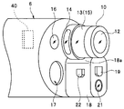
- FIG. 2 is a perspective view showing the configuration of the distal end portion of the insertion portion of the endoscope.
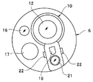
- FIG. 3 is a front view showing the configuration of the distal end portion of the insertion portion of the endoscope.
- FIG. 4 is a cross-sectional view of the main part showing the configuration of the distal end portion of the insertion portion in the endoscope system according to the first embodiment.
- FIG. 5 is a diagram illustrating an example of an observation image displayed on the monitor by image processing by the video processor of the endoscope system.
- an endoscope system 1 includes an endoscope 2 that images an observation target (subject) and outputs an imaging signal, and a light source device that supplies illumination light for illuminating the observation target 31, a video processor 32 that is an image processing device that generates and outputs a video signal corresponding to the imaging signal, and a monitor 35 that displays an observation image that is an endoscopic image corresponding to the video signal.
- the endoscope 2 includes an operation unit 3 that is held and operated by an operator, an elongated insertion unit 4 that is formed on the distal end side of the operation unit 3 and is inserted into a body cavity that is a subject, and the operation unit 3. And a universal cord 5 provided with one end portion so as to extend from the side portion.
- the endoscope 2 is a wide-angle endoscope capable of observing a field of view of 180 degrees or more by displaying a plurality of field images.
- the body cavity particularly in the large intestine, the back of the eyelid or the boundary of the organ
- operations such as temporary fixing by twisting the insertion portion 4, reciprocating movement, and hooking the intestinal wall are generated as in the case of a normal large intestine endoscope. To do.
- the insertion portion 4 to be inserted into the subject includes a hard tip portion 6 provided on the most distal side, a bendable bending portion 7 provided on the rear end of the tip portion 6, and a rear end of the bending portion 7. And a flexible tube portion 8 having a long length and flexibility. Further, the bending portion 7 performs a bending operation according to the operation of the bending operation lever 9 provided in the operation portion 3. On the other hand, as shown in FIG. 2, a columnar cylindrical portion 10 is formed at the distal end portion 6 of the insertion portion 4 so as to protrude from a position eccentric to the upper side from the center of the distal end surface of the distal end portion 6. ing.
- An objective optical system (not shown) for observing both the front field and the side field is provided at the tip of the cylindrical part 10. Moreover, the front-end
- the side observation window 13 makes it possible to acquire a side view image by capturing the return light, that is, the reflected light, from the observation target incident from the periphery of the cylindrical cylindrical portion 10 in the side view.
- the side view mirror lens 15 is provided.
- the image of the observation object in the field of view of the front observation window 12 is formed in the center as a circular front field image at the imaging position of the objective optical system (not shown), and the field of view of the side observation window 13
- the imaging surface of the imaging element 40 is arranged so that the image of the observation object inside is formed as an annular side field image on the outer periphery of the front field image.
- the front observation window 12 is provided in the insertion unit 4, and constitutes a first subject image acquisition unit that acquires a first subject image from a first region including the front in the first direction.
- the side observation window 13 is provided in the insertion unit 4 and constitutes a second subject image acquisition unit that acquires a second subject image from a second region including a side that is in a second direction different from the front.
- the front observation window 12 is a front image acquisition unit that acquires a subject image of a region including the front of the insertion unit
- the side observation window 13 is a side of acquiring a subject image of a region including the side of the insertion unit.
- the front observation window 12 is disposed at the distal end portion 6 in the longitudinal direction of the insertion portion 4 so as to acquire a subject image from the front in which the insertion portion 4 is inserted. It is arranged along the outer diameter direction of the insertion portion 4 so as to acquire a subject image from the direction.
- the first subject image is a subject image in the first direction including the front of the insertion portion substantially parallel to the longitudinal direction of the insertion portion 4
- the second subject image is in the longitudinal direction of the insertion portion 4.
- it is a subject image in the second direction including the side of the insertion portion that intersects at an angle such as a right angle.
- the imaging device 40 as an imaging unit photoelectrically converts the front visual field image and the side visual field image on one imaging surface, and the image signal of the front visual field image and the image signal of the side visual field image are obtained by the imaging device 40. It is generated by cutting out from the obtained image. That is, the image sensor 40 constitutes an imaging unit that captures the first subject image and the second subject image, and is electrically connected to the video processor 32.
- the distal end surface of the distal end portion 6 is disposed at a position adjacent to the cylindrical portion 10 and is disposed in the insertion portion 4 and the front illumination window 16 that emits illumination light in the range of the front visual field of the front observation window 12.
- a distal end opening 17 is provided which communicates with a treatment instrument channel (not shown) formed of a tube or the like and can project the distal end of the treatment instrument inserted into the treatment instrument channel.
- the distal end portion 6 of the insertion portion 4 has a support portion 18 provided so as to protrude from the distal end surface of the distal end portion 6, and the support portion 18 is positioned adjacent to the lower side of the cylindrical portion 10.
- the support portion 18 is configured to be able to support or hold the protruding members arranged to protrude from the distal end surface of the distal end portion 6.
- the support portion 18 includes a front observation window nozzle portion 19 that emits a gas or a liquid for cleaning the front observation window 12 as each of the protruding members described above, and light for illuminating the front direction. Is configured to be able to support or hold another front illumination window 21 that emits light and a side observation window nozzle portion 22 that emits a gas or liquid for cleaning the side observation window 13.
- the support unit 18 acquires a side field image including any one of the projecting members when each projecting member described above, which is an object different from the original observation target, appears in the side field of view. It is formed with a shielding portion 18a, which is an optical shielding member, so as not to be disturbed. That is, by providing the shielding portion 18a on the support portion 18, a side-view visual field image that does not include any of the front observation window nozzle portion 19, the front illumination window 21, and the side observation window nozzle portion 22 is obtained. Obtainable. As shown in FIGS. 2 and 3, the side observation window nozzle portion 22 is provided at two locations of the support portion 18 and is disposed so that the tip protrudes from the side surface of the support portion 18.
- the operation unit 3 includes an air / liquid feeding operation button 24 a capable of giving an operation instruction for injecting a gas or a liquid for cleaning the front observation window 12 from the nozzle 19 for the front observation window,
- An air / liquid feeding operation button 24b capable of operating instructions for injecting a gas or a liquid for cleaning the side observation window 13 from the side observation window nozzle section 22 is provided.
- Air supply and liquid supply can be switched by pressing the buttons 24a and 24b.
- a plurality of air / liquid feeding operation buttons are provided so as to correspond to the respective nozzle portions. For example, by operating one air / liquid feeding operation button, Gas or liquid may be ejected from both of the side observation window nozzle portions 22.
- a plurality of scope switches 25 are provided at the top of the operation unit 3 and assign functions for each switch so as to output signals corresponding to various descriptions of ON or OFF that can be used in the endoscope 2. It has a configuration that can. Specifically, the scope switch 25 has a function of outputting signals corresponding to, for example, start and stop of forward water supply, execution and release of freeze for still image shooting, and notification of the use state of the treatment instrument. Can be assigned as a function for each switch.
- At least one of the functions of the air / liquid feeding operation buttons 24a and 24b may be assigned to one of the scope switches 25.
- the operation unit 3 is provided with a suction operation button 26 that can instruct a suction unit or the like (not shown) to suck and collect mucus or the like in the body cavity from the distal end opening 17. Yes.
- the mucus etc. in the body cavity sucked in response to the operation of the suction unit are provided in the vicinity of the front end of the distal end opening 17, the treatment instrument channel (not shown) in the insertion section 4, and the operation section 3. After passing through the treatment instrument insertion port 27, it is collected in a suction bottle or the like of a suction unit (not shown).
- the treatment instrument insertion port 27 communicates with a treatment instrument channel (not shown) in the insertion portion 4 and is formed as an opening into which a treatment instrument (not shown) can be inserted. That is, the surgeon can perform treatment using the treatment tool by inserting the treatment tool from the treatment tool insertion port 27 and projecting the distal end side of the treatment tool from the distal end opening portion 17.
- a connector 29 that can be connected to the light source device 31 is provided at the other end of the universal cord 5.
- the tip of the connector 29 is provided with a base (not shown) serving as a connection end of the fluid conduit and a light guide base (not shown) serving as a supply end of illumination light. Further, an electrical contact portion (not shown) capable of connecting one end of the connection cable 33 is provided on the side surface of the connector 29. Furthermore, a connector for electrically connecting the endoscope 2 and the video processor 32 is provided at the other end of the connection cable 33.
- the universal cord 5 includes a plurality of signal lines for transmitting various electrical signals and a light guide for transmitting illumination light supplied from the light source device 31 in a bundled state.
- the light guide built in from the insertion portion 4 to the universal cord 5 has an end portion on the light emission side branched in at least two directions in the vicinity of the insertion portion 4, and a light emission end surface on one side has the front illumination window 16 and 21 and the light emitting end face on the other side is arranged in the side illumination window 14.
- the light guide has a configuration in which the light incident side end is disposed on the light guide cap of the connector 29.
- the video processor 32 which is an image processing device and an image signal generation device outputs a drive signal for driving the image sensor 40 provided at the distal end portion 6 of the endoscope 2. Then, as will be described later, the video processor 32 performs signal processing (cuts out a predetermined area) on the imaging signal output from the imaging element 40 in accordance with the usage state of the endoscope 2. A video signal is generated and output to the monitor 35.
- Peripheral devices such as the light source device 31, the video processor 32, and the monitor 35 are arranged on a gantry 36 together with a keyboard 34 for inputting patient information and the like.
- the light source device 31 includes a lamp. Light emitted from the lamp is guided to the connector portion to which the connector 29 of the universal cord 5 is connected via the light guide, and the light source device 31 supplies illumination light to the light guide in the universal cord 5. To do.
- FIG. 4 is a cross-sectional view of a main part showing the configuration of the distal end portion 6 of the insertion portion 4 in the endoscope system according to the first embodiment, and the objective optical system 11 and the side illumination window 14 that serve both as the front and the side.
- the configuration of the peripheral part is shown.
- An imaging element in which a front lens 41, a mirror lens 15 and a rear lens group 43 each having a rotationally symmetric shape are arranged on an optical axis that coincides with the imaging center O along the central axis of the cylindrical portion 10 protruding from the distal end portion 6.
- An objective optical system 11 that forms an image at 40 is formed.
- a cover glass 42 is provided on the front surface of the image sensor 40. The front lens 41, the mirror lens 15, and the rear lens group 43 are fixed to a lens frame in the cylindrical portion 10.
- the front lens 41 constituting the objective optical system 11 and provided in the circular front observation window 12 forms a wide-angle front field of view with the distal end side along the insertion direction of the insertion portion 4 as an observation field.
- the mirror lens 15 as a reflection optical system disposed immediately after the front lens 41 reflects light incident from the side surface direction twice on the cemented surface and the front surface as shown in FIG. It consists of two lenses that guide light to the side.
- the lens portion of the mirror lens 15 that faces the front lens 41 also serves to refract light from the front lens 41 and guide it to the rear lens group 43 side.
- the side observation window 13 has a predetermined viewing angle with the optical axis in the lateral direction being substantially the center with respect to the insertion portion major axis direction.
- a substantially annular observation field that covers the entire circumference in the circumferential direction of the insertion portion is formed.
- the light incident on the front lens 41 forming the front observation window 12 from the subject side and the mirror lens 15 forming the side observation window 13 on the subject side in the field of view. 1 shows a schematic path of a light ray incident from.
- an image of the subject in the front visual field provided in the center side in the insertion direction by the front lens 41 of the front observation window 12 is formed in a circular shape as a front visual field image.
- an image of the subject in the side field is formed in a ring shape by the mirror lens 15 facing the side observation window 13 on the outer peripheral side of the front field image, and is acquired as a side field image. Will be.
- the support portion 18 forms a shielding portion 18a that mechanically shields light from the subject side that enters the annular side field of view. Moreover, in this embodiment, it is set as the structure which does not radiate
- the side visual field image is acquired by using the double reflection optical system in the present embodiment.
- Side view images may be acquired using a system.
- the direction of the side view image may be aligned by image processing or the like as necessary.
- Side illumination windows 14 are provided at a plurality of locations on the outer peripheral surface near the base end adjacent to the side observation window 13 in the cylindrical portion 10. In the present embodiment, side illumination windows 14 are provided at two locations on both the left and right sides in the circumferential direction, and side illumination light is emitted to the entire area in the circumferential direction except the lower side where the support portion 18 is provided.
- the distal end side of the light guide 44 as a light emitting member arranged along the longitudinal direction of the distal end portion 6 is a cylindrical member 10 a constituting the cylindrical portion 10 protruding from the distal end surface of the distal end portion 6. It is extended to the vicinity of the base end.
- the tip surface of the light guide 44 is arranged near the side surface near the base end of the cylindrical portion 10 (the outer peripheral side of the rear lens group 43).
- the light guide 44 emits light guided by the tip surface. It becomes an end face and emits light toward the tip.
- the emission end face is circular, but is not limited to a circle, and may be an irregular shape including an ellipse or a polygon.
- a recess is formed that extends in a strip shape along the outer periphery of the cylindrical side surface of the cylindrical portion 10 around the position and forms a light guide groove 45 as a groove portion for guiding light.
- the reflection part 46a on the inner surface of the light guide groove 45 formed by the reflection member 46 is a substantially hemispherical concave surface in the longitudinal section shown in FIG.
- the reflecting portion 46 a has a hemispherical concave surface that is longer than the exit end surface of the light guide 44 along the circumferential direction of the cylindrical portion 10.
- the reflecting portion 46a reflects the light emitted from the emitting end face toward the tip end side of the tip portion 6 by the reflecting portion 46a to change the traveling direction of the light in the side surface direction, and along the circumferential direction. Then, the light is guided in a wide range of side directions and emitted from the side illumination window 14 to illuminate the observation field side (observation target side) of the side observation window 13. Accordingly, the light emitted from the light guide groove 45 in the side surface direction becomes side illumination light.
- the reflective portion 46 a can be formed by providing a thin metal film having a high reflectance such as aluminum, chromium, nickel chrome, silver, or gold on the inner surface of the reflective member 46.
- the reflecting member 46 is provided in the recess of the light guide groove 45 so that the light guide groove 45 provided with the reflection part 46a is formed long along the outer periphery of the side surface of the cylindrical part 10. It is arranged. Further, the light guide 44 is disposed so that the light emitting end face of the light guide 44 as a light emitting member is located near the center position in the circumferential direction of the reflecting member 46 or the light guide groove 45.
- the light emitted from the emission end face of the light guide 44 is reflected by the reflecting portion 46a arranged so as to form a reflection surface around the emission end face, and the side illumination window 14 provided with the light guide groove 45 is provided. Illumination light is emitted from a wide range to the side.
- FIG. 5 shows an example of an endoscopic image displayed on the monitor 35.
- An observation image 50 that is an endoscopic image displayed on the display screen 35 a of the monitor 35 is a substantially rectangular image and includes two portions 52 and 53.
- the central circular portion 52 is a portion for displaying a front visual field image
- the C-shaped portion 53 around the central portion 52 is a portion for displaying a side visual field image.
- the image displayed in the portion 52 of the endoscopic image displayed on the monitor 35 and the image displayed in the portion 53 are the same as the image of the subject in the front view and the image of the subject in the side view, respectively. Is not limited.
- the front visual field image is displayed on the display screen 35a of the monitor 35 so as to be substantially circular
- the side visual field image is displayed so as to be substantially circular surrounding at least a part of the periphery of the front visual field image. It is displayed on the screen 35a. Therefore, a wide-angle endoscopic image is displayed on the monitor 35.
- the endoscopic image shown in FIG. 5 is generated from the acquired image acquired by the image sensor 40 (FIG. 2).
- the observation image 50 corresponds to the portion 52 except for the mask region 54 that is blacked out by photoelectrically converting the subject image projected on the imaging surface of the imaging device 40 by the objective optical system provided in the distal end portion 6.
- the central front-view image portion and the side-view image portion corresponding to the portion 53 are generated by synthesis.
- FIG. 6 is a block diagram showing the configuration of the video processor 32. In FIG. 6, only the configuration related to the function of the present embodiment described below is shown, and the components related to other functions such as image recording are omitted.
- the video processor 32 includes a control unit 60, an analog / digital conversion unit (hereinafter referred to as an A / D conversion unit) 61, a preprocessing unit 62, a dimming unit 63, an enlargement / reduction unit 64, and a positional deviation correction unit 65.
- the video processor 32 has a function of generating an image subjected to image processing.
- the endoscope 2 has a nonvolatile memory 70 such as a flash memory. Deviation amount data, which will be described later, is written and stored in the memory 70 by the video processor 32 and can be read out by the video processor 32.
- the control unit 60 includes a central processing unit (CPU), ROM, RAM, etc., and executes predetermined software programs in response to instructions such as user command input from an operation panel (not shown), and controls various control signals and data. A signal is generated or read out, and necessary circuits and units in the video processor 32 are controlled.
- CPU central processing unit
- ROM read-only memory
- RAM random access memory
- the A / D conversion unit 61 includes an A / D conversion circuit, and is a circuit that converts an imaging signal from the imaging element 40 of the endoscope 2 from an analog signal to a digital signal.
- the preprocessing unit 62 is a circuit that performs processing such as color filter conversion on the imaging signal from the imaging device 40 of the endoscope 2 and outputs a video signal.
- the light control unit 63 is a circuit that determines the brightness of the image based on the video signal and outputs a light control signal to the light source device 31 based on the light control state of the light source device 31.
- the enlargement / reduction unit 64 enlarges or reduces the image of the video signal output from the preprocessing unit 62 in accordance with the size and format of the monitor 35, and sends the enlarged or reduced image signal to the misalignment correction unit 65. Output.
- the position shift correction unit 65 estimates two center coordinates of the front visual field image FV and the side visual field image SV, and executes a process of calculating a deviation amount between the two estimated central coordinates.
- the misalignment correction unit 65 stores the calculated shift amount in the memory 70 of the endoscope 2 and also in the register 69.
- the misregistration correction unit 65 outputs a video signal including the input front visual field image FV and side visual field image SV to the boundary correction unit 66.
- the boundary correction unit 66 cuts out the front visual field image FV and the side visual field image SV from the input video signal using the deviation amount data stored in the register 69, and executes a predetermined enlargement process.
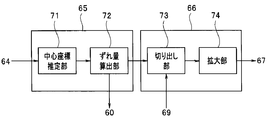
- FIG. 7 is a block diagram showing the configuration of the misalignment correction unit 65 and the boundary correction unit 66.
- the positional deviation correction unit 65 includes a center coordinate estimation unit 71 and a deviation amount calculation unit 72.
- the center coordinate estimation unit 71 is a circuit that calculates and estimates a shift amount between the center CF of the front visual field image portion FVa and the center CS of the side visual field image portion SVa on the imaging surface 40a of the image sensor 40.
- the center coordinate estimation unit 71 has a circular front visual field.
- the center CF of the image portion FVa and the center CS of the annular side field image portion SVa can be calculated.
- the control unit 60 reads data from the memory 70 of the endoscope 2 to determine the presence / absence of the deviation amount data.
- the central coordinate estimation unit 71 and the deviation amount calculation unit The misregistration correction unit 65 is controlled to operate 72.
- the boundary correction unit 66 includes a cutout unit 73 and an enlargement unit 74.
- the cutout unit 73 cuts out the front view image FV of the front view image portion FVa and the side view image SV of the side view image portion Sva from the input video signal based on the shift amount data read from the register 69.
- the enlarging unit 74 performs an enlarging process on the cut-out front visual field image FV at a predetermined magnification, and outputs it to the synthesizing unit 67.
- the composition unit 67 determines that the front visual field image FV and the lateral visual field image FV and the lateral visual field image SV are aligned so that the centers CF and CV of the input visual field image FV and the lateral visual field image SV coincide with the center C of the imaging surface 40 a.
- the image SV is synthesized and the synthesized image is output to the image output unit 68. Note that the synthesizing unit 67 also performs mask processing.
- the image output unit 68 generates an image signal including the front view image FV and the side view image SV from the combining unit 67 by image processing, converts the image signal into a display signal, and outputs the display signal to the monitor 35.
- the image output unit 68 receives the image signal from the synthesizing unit 67 and generates a display signal for displaying the image signal based on the front visual field image FV and the side visual field image SV on the monitor 35 as a display unit.
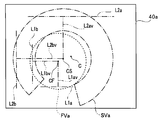
- FIG. 8 is a diagram for explaining a positional shift between the center CF of the front visual field image portion FVa and the center CS of the side visual field image portion SVa projected on the imaging surface 40a of the image sensor 40 in the central coordinate estimation unit 71. It is.
- a front field image portion FVa corresponding to a circular front field image FV by a front field optical system including the front lens 41 of the front observation window 12 and a mirror facing the side observation window 13.
- a side field image portion SVa corresponding to the annular side field image SV by the side field optical system including the lens 15 is formed.
- the circular front-field image portion FVa (shown by a dotted line) depends on the processing accuracy of the lenses for fixing the lenses of the objective optical system or the frame for fixing the image pickup device 40 or variations in assembly.
- the center CF and the center CS of the annular side field image portion SVa (indicated by the alternate long and short dash line) may be relatively displaced.
- center CF of the front visual field image portion FVa and the center CS of the side visual field image portion SVa may be shifted from the center C of the imaging surface 40a of the image sensor 40.
- the center CF of the front visual field image portion FVa and the center CS of the side visual field image portion SVa are also deviated from the center C of the imaging surface 40a.
- the position shift correction unit 65 of the video processor 32 detects the relative shift amount between the center CF of the front view image portion FVa and the center CS of the side view image portion SVa or the front view image with respect to the center C of the imaging surface 40a.
- the shift amounts of the center CF of the portion FVa and the center CS of the side field image portion SVa are calculated.
- the positional deviation correction unit 65 calculates the deviation amounts of the center CF of the front visual field image portion FVa and the center CS of the side visual field image portion SVa with respect to the center C of the imaging surface 40a.
- the misregistration correction unit 65 is operated.
- a video signal of an image including both the front visual field image portion FVa and the side visual field image portion SVa is input to the center coordinate estimation unit 71.
- the central coordinate estimation unit 71 may be operated according to a user instruction, or may be automatically operated when it is determined that the deviation amount data is not stored in the memory 70. .
- the center coordinate estimation unit 71 extracts the front view image portion FVa and the side view image portion SVa by image processing based on the luminance value of the pixel of the input video signal, and obtains the center of each extracted portion.
- the center coordinate estimation unit 71 determines the pixel area on the imaging surface 40a corresponding to the circular front view image portion FVa and the imaging corresponding to the annular side field image portion SVa from the difference in luminance value of each pixel. A pixel region on the surface 40a can be extracted.
- the coordinates of the center CF of the front visual field image portion FVa on the imaging surface 40a are assumed to be two appropriate straight lines L1a and L1b (indicated by two-dot chain lines) passing through the circular front visual field image portion FVa. It can be obtained by calculating the intersection of vertical bisectors L1av and L1bv (indicated by a two-dot chain line) for the line segments inside the respective circles of the straight lines L1a and L1b.
- the coordinates of the center CS of the side field image portion SVa on the imaging surface 40a are assumed to be two appropriate straight lines L2a and L2b (indicated by a two-dot chain line) passing through the annular side field image portion SVa. Then, it can be obtained by calculating the intersection point of the perpendicular bisectors L2av and L2bv for the line segment inside the outer circle of the side field image portion SVa of each of the straight lines L2a and L2b.
- the coordinates of the center C of the imaging surface 40a are (x0, y0), the coordinates of the center CF of the obtained front visual field image portion FVa are (xf1, yf1), and the center CS of the obtained side visual field image portion SVa is Let the coordinates be (xs1, ys1).
- the deviation amount calculation unit 72 calculates the deviation amount from the center CF of the front visual field image portion FVa and the center CS of the side visual field image portion SVa obtained by the central coordinate estimation unit 71.
- a deviation amount dfx in the x-axis direction of the center CF with respect to the center C of the imaging surface 40a is expressed by Expression (1).
- the center coordinate estimation unit 71 obtains the center CF of the front visual field image portion FVa and the center CS of the side visual field image portion SVa
- the shift amount calculation unit 72 obtains the front visual field obtained by the central coordinate estimation unit 71.
- the shift amount can be calculated from the coordinates of the center CF of the image portion FVa and the center CS of the side field image portion SVa.
- the control unit 60 writes the calculated deviation amount data in the memory 70 and writes it in the register 69.
- the control unit 60 turns on the power of the endoscope system 1 and the central coordinate estimation unit 71 has been operated. Since the deviation amount data can be read from the memory 70, the read deviation amount data is written in the register 69.
- the boundary correcting unit 66 changes the image signal obtained by changing the arrangement of the front visual field image FV and the side visual field image based on the positional relationship detection information stored in the memory 70 until the positional relationship detection signal is updated. Generate.
- the control unit 60 turns on the endoscope system 1. Therefore, the deviation amount data cannot be read from the memory 70. In such a case, the control unit 60 operates the center coordinate estimation unit 71 and the deviation amount calculation unit 72 and performs the calculations of the above-described equations (1) to (4) to obtain the deviation amount data Dfx, Dfy, Dsx. , Dsy are calculated and stored in the memory 70 and written to the register 69.
- the deviation amount data Dfx, Dfy, Dsx, Dsy is information indicating the positional relationship between the front visual field image portion FVa and the side visual field image portion SVa.
- the memory 70 is a storage unit that stores positional relationship detection information.
- the positional deviation correction unit 65 includes the front visual field image portion Fva, which is the first portion on which the front subject image is formed, in the imaging element 40 that captures the front subject image and the side subject image.
- a subject image position detection unit that generates positional relationship detection information by detecting the positional relationship with the side field image portion SVa that is the second portion on which the subject image is formed.
- the positional relationship is indicated by a deviation amount of the portion FVa with respect to the center C of the imaging surface 40a, which is a predetermined position for an image acquired by the imaging element 40, and a deviation amount of the portion SVa with respect to the center C of the imaging surface 40a. . Therefore, the positional relationship detection information includes these two deviation amounts.
- the deviation amount calculation unit 72 performs the above-described deviation amount calculation processing and outputs a video signal to the clipping unit 73.
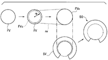
- FIG. 9 is a diagram for explaining processing in the cutout unit 73, the enlargement unit 74, and the synthesis unit 67.
- the cutout unit 73 cuts out the front visual field image FV and the side visual field image SV from the input video signal based on the deviation amount data Dfx, Dfy, Dsx, Dsy, and further, as shown in FIG. A central image FVc having a predetermined radius rp is cut out from the visual field image FV. As a result, the peripheral image of the front visual field image FV is not used as the observation image.
- the enlargement unit 74 enlarges the central image FVc with a predetermined magnification mr and generates an enlarged central image FVe.
- the magnification mr is a value such that the radius of the enlarged enlarged central image FVe is larger than the diameter of the front visual field image FV cut out by the cutout unit 73.
- the combining unit 67 combines the enlarged central image FVe and the side view image SV, performs necessary mask processing, and outputs the result to the image output unit 68.
- the synthesized observation image 50 is an image in which the inner peripheral edge portion of the lateral visual field image SV is covered with the enlarged central image FVe.
- the front visual field image FV is obtained.
- the boundary area of the side view image SV becomes a smooth image area.
- the boundary correction unit 66 performs image processing based on the positional relationship detection information, and the center CF that is the reference position provided in the front visual field image portion FVa and the center CS that is the reference position provided in the side visual field image portion SVa. And an image signal generation unit that generates an image signal in which the front visual field image FV and the side visual field image SV are arranged.
- the boundary correction unit 66 is configured so that both the center position of the subject image of the front visual field image portion FVa and the center position of the subject image of the side visual field image portion SVa coincide with the center C of the imaging surface 40a. Although the positions of the front visual field image FV and the side visual field image SV are changed, the boundary correction unit 66 determines the coordinates of the center position of the subject image of the front visual field image part FVa and the subject image of the side visual field image part SVa. Processing for changing the position of at least one of the front visual field image FV and the side visual field image SV may be performed so as to correct the deviation of the coordinates of the center position.
- the boundary correction unit 66 based on the positional relationship detection information indicating the positional relationship between the front visual field image portion FVa and the side visual field image portion SVa, one of the front visual field image portion FVa and the side visual field image portion SVa.
- the arrangement is changed according to the other position of the front visual field image portion FVa and the side visual field image portion SVa.
- the coordinates of the center position of the subject image are the coordinates of the pixels on the monitor 35 which is the display unit on which the front visual field image FV and the side visual field image SV are displayed, and the amount of deviation is the number of pixels on the coordinates. It may be converted and expressed.
- the control unit 60 may read out from the memory 70 and store it in the register 69.
- the boundary correction unit 66 reads information on the predetermined radius rp and the predetermined magnification mr from the register 69, and cuts out and enlarges the central image FVc.
- the boundary between the front visual field image FV and the side visual field image SV becomes inconspicuous. Note that a general smoothing process may be performed on the boundary region between the synthesized front view image FV and side view image SV.
- the control unit 60 reads out the misregistration amount data from the memory 70, reads out the misregistration amount data, and registers 69
- Boundary correction unit 66 performs boundary correction based on the deviation amount data stored in.
- the processing of the misalignment correction unit 65 may be executed when the endoscope 2 is manufactured, or may be executed when the endoscope 2 is connected to the video processor 32 for the first time even if it is not executed at the time of manufacture. The Further, the processing of the misalignment correction unit 65 may be executed when the endoscope 2 is repaired.
- the optical system of the front visual field image FV and the side visual field image SV due to the processing accuracy of the frame for fixing the lens of the objective optical system or the image sensor or the variation during assembly. Even if there is a difference between them, it is possible to provide an endoscope system in which the user does not feel uncomfortable with the front visual field image FV and the side visual field image SV simultaneously displayed on the monitor 35.
- the boundary correction process can be performed with high accuracy.
- the endoscope system 1 includes an endoscope 2 that obtains a front-field image and a side-field image arranged so as to surround the front-field image with a single image sensor.
- the endoscope system 1A according to the second embodiment includes an endoscope 2A that obtains a front-field image and a side-field image with separate image sensors.
- the configuration of the endoscope system 1A according to the second embodiment is substantially the same as that of the endoscope system 1 described in the first embodiment shown in FIG. 1, and the same constituent elements are denoted by the same reference numerals. The description is omitted.
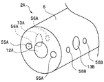
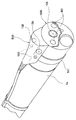
- FIG. 10 is a simplified schematic perspective view of the distal end portion 6 of the endoscope 2A of the present embodiment.
- FIG. 11 is a schematic configuration diagram showing the internal configuration of the distal end portion 6. In FIG. 10 and FIG. 11, elements such as the treatment instrument opening and the washing nozzle are omitted.
- an imaging unit 51A for a front visual field is provided on the distal end surface of the cylindrical distal end portion 6 of the endoscope 2A.
- Two imaging units 51B and 51C for side field of view are provided on the side surface of the distal end portion 6 of the endoscope 2A.
- the three imaging units 51A, 51B, 51C have imaging elements 40A, 40B, 40C, respectively, and each imaging unit is provided with an objective optical system (not shown).
- Each imaging unit 51A, 51B, 51C is disposed on the back side of the front observation window 12A and the side observation windows 13A, 13B, respectively.
- the imaging units 51A, 51B, 51C receive reflected light from the subject illuminated by the illumination light emitted from the two illumination windows 55A, 56A, 56B, respectively, and output an imaging signal.
- the front observation window 12A is disposed at the distal end portion 6 of the insertion portion 4 in the direction in which the insertion portion 4 is inserted.
- the side observation windows 13A and 13B are arranged at substantially equal angles in the circumferential direction of the distal end portion 6 toward the outer diameter direction of the insertion portion 4 on the side surface portion of the insertion portion 4, and the side observation windows 13A and 13B 13B is arrange
- Image sensors 40A, 40B, and 40C of the imaging units 51A, 51B, and 51C are electrically connected to the video processor 32A (FIG. 12), and are controlled by the video processor 32A to output an imaging signal to the video processor 32A.
- Each of the imaging units 51A, 51B, and 51C is an imaging unit that photoelectrically converts a subject image.
- the front observation window 12A is provided in the insertion unit 4, and constitutes a first image acquisition unit that acquires the image of the first subject image from the front in the first direction, and the side observation windows 13A and 13B.
- the first subject image is a subject image in the first direction including the front of the insertion portion substantially parallel to the longitudinal direction of the insertion portion 4, and the second subject image is in the longitudinal direction of the insertion portion 4. It is a to-be-photographed object image of the 2nd direction containing the insertion part side substantially orthogonal.
- the front observation window 12A is a front image acquisition unit that acquires a subject image in a direction including the front of the insertion unit
- the side observation windows 13A and 13B are sides on which a subject image in a direction including the side of the insertion unit is acquired. It is a way image acquisition part.
- the imaging unit 51A is an imaging unit that photoelectrically converts an image from the front observation window 12A
- the imaging units 51B and 51C are imaging units that photoelectrically convert two images from the side observation windows 13A and 13B, respectively. That is, the imaging unit 51A is an imaging unit that captures a subject image for acquiring a front visual field image
- the imaging units 51B and 51C are imaging units that capture a subject image for acquiring a side visual field image, respectively.
- the image signal of the front visual field image is generated from the image obtained in the imaging unit 51A
- the image signals of the two side field images are generated from the images obtained in the imaging units 51B and 51C.
- a light emitter such as a light guide tip or a light emitting diode (LED) (not shown) is disposed in the tip 6 behind the illumination windows 55A, 56A, and 56B.
- LED light emitting diode
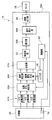
- FIG. 12 is a block diagram showing the configuration of the video processor 32A according to the present embodiment.
- FIG. 12 only the configuration related to the function of the present embodiment described below is shown, and the components related to other functions such as image recording are omitted.
- the same components as those in the video processor 32 of the first embodiment are denoted by the same reference numerals and description thereof is omitted.
- the video processor 32A includes a control unit 60, an A / D conversion unit 61A, a misalignment correction unit 65A, a boundary correction unit 66A, a synthesis unit 67A, and a preprocessing unit 62.
- the optical unit 63 ⁇ / b> A, the enlargement / reduction unit 64 ⁇ / b> A, the image output unit 68, and the register 69 are provided.
- the A / D converter 61A includes three A / D converter circuits.
- Each A / D conversion circuit is a circuit that converts an imaging signal from each imaging element 40A, 40B, 40C of the endoscope 2A from an analog signal to a digital signal.
- the misregistration correction unit 65A has a center coordinate estimation unit 71 and a misregistration amount calculation unit 72 shown in FIG. 7, and each of the three images obtained by the three image pickup devices 40A, 40B, and 40C is shifted. A process for calculating the quantity is executed.
- the position shift correction unit 65A stores the calculated three shift amount data for the three image sensors 40A, 40B, and 40C in the memory 70 of the endoscope 2 and also in the register 69.
- the misregistration correction unit 65A outputs the input video signals of the three images to the boundary correction unit 66A.
- the boundary correction unit 66A has a cutout unit 73 and an enlargement unit 74 shown in FIG. 7, and uses the three shift amount data stored in the register 69 to cut out an image for each input video signal. A predetermined enlargement process is executed.
- the synthesizing unit 67A synthesizes the three endoscopic images to display them side by side on the screen of the monitor 35, and outputs the synthesized image to the preprocessing unit 62.
- there is one monitor 35 but the front view image and the two side view images may be displayed on separate monitors. In such a case, the combining unit 67A is not necessary.
- the dimming unit 63A is a circuit that determines the brightness of each image in the video signal received from the preprocessing unit 62, and outputs a dimming control signal to the light source device 31 based on the dimming state of the light source device 31. is there.
- the enlargement / reduction unit 64A enlarges or reduces the image of the video signal from the preprocessing unit 62 according to the size and format of the monitor 35, and outputs the enlarged or reduced image signal to the image output unit 68.
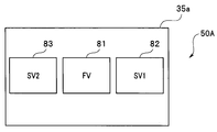
- FIG. 13 is a diagram illustrating an example of an observation image displayed on the monitor 35 by image processing performed by the video processor 32A of the endoscope system 1A.
- an observation image 50 ⁇ / b> A that is an endoscopic image displayed on the display screen 35 a of the monitor 35 includes three image display portions 81, 82, and 83.
- Each of the image display portions 81, 82, 83 is a substantially rectangular image
- the front view image FV is displayed at the center
- the right side view image SV1 is displayed on the right side
- the left side is displayed on the left side.
- a square field image SV2 is displayed. That is, the image output unit 68 displays the two side field images SV1 and SV2 on the monitor 35 as a display unit so as to be adjacent to the front field image FV.
- the front visual field image FV is generated from an image acquired by the image sensor 40A (FIG. 11) of the imaging unit 51A.
- the image of the image display portion 82 is generated from an image acquired by the image sensor 40B (FIG. 11) of the imaging unit 51B.
- the image of the image display portion 83 is generated from an image acquired by the imaging element 40C (FIG. 11) of the imaging unit 51C.
- the imaging unit 51A images the front of the distal end portion 6, the two imaging units 51B and 51C capture the lateral side of the distal end portion 6 in opposite directions.
- the three imaging elements 40A, 40B, and 40C have different processing accuracy or assembling variations of the lenses of the objective optical systems of the imaging units 51A, 51B, and 51C or the frames for fixing the imaging elements 40A, 40B, and 40C.
- Each central axis may be displaced from a predetermined optical axis in the horizontal and vertical directions.
- the misregistration correction unit 65A that executes misregistration correction processing calculates the misregistration amount from a predetermined position for three images by image processing. Also in the present embodiment, as in the first embodiment, when the endoscope 2A is manufactured or when the endoscope 2A is used for the first time, the endoscope 2A is connected to the video processor 32A to supply power. The misregistration correction unit 65A is controlled by the control unit 60 so as to operate when turned on.
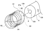
- FIG. 14 is a perspective view showing the configuration of the cap 91.
- the cap 91 is a member having a cylindrical shape with a closed end.
- the cap 91 has an opening 91 a into which the distal end portion 6 of the insertion portion 4 can be inserted from the proximal end side of the cap 91.
- predetermined reference graphics are provided by printing or the like.
- the reference image provided on the inner wall surface 92 on the distal end side of the cap 91 is a cross line 94 extending in the vertical direction and the horizontal direction, respectively.
- the reference image provided on the inner peripheral surface 93 of the cap 91 is a lattice line 95 extending in the vertical direction and the horizontal direction.
- the user inserts the distal end portion 6 into the cap 91 from the opening 91a, covers the distal end portion 6 with the cap 91, and then operates the misalignment correcting portion 65A.
- each imaging element 40A, 40B, 40C images a cross position 94 and a grid line 95 in the cap 91 at a predetermined angle around the axis of the distal end portion 6 at a predetermined angle, respectively. Etc.) are provided on the cap 91 and the tip 6.
- the image sensor 40 ⁇ / b> A images the cross line 94 in the cap 91.
- the vertical direction of the image sensor 40A coincides with the vertical line direction of the cross line 94
- the horizontal direction of the image sensor 40A coincides with the horizontal line direction of the cross line 94.
- the image sensor 40 ⁇ / b> A is obtained when the crosshair 94 in the cap 91 is imaged.
- the vertical directions of the imaging elements 40B and 40C coincide with the vertical direction of the grid lines 95.
- FIG. 15 is a diagram for explaining the displacement of the subject image formed on the imaging surfaces of the imaging elements 40A, 40B, and 40C.
- regions 40AI, 40BI, and 40CI indicate image ranges obtained on the imaging surfaces of the imaging elements 40A, 40B, and 40C, respectively.
- a region of a predetermined size in the image signal of each image sensor is cut out from the image obtained by each image sensor.
- the reference point for clipping is the center point of each image (hereinafter referred to as the image center point).
- a predetermined area is cut out from the area 40AI obtained by the image pickup element 40A with reference to the image center point CC, and a predetermined area is cut out from the area 40BI obtained from the image pickup element 40B with reference to the image center point CR.
- a predetermined region is cut out from the region 40CI obtained by 40C using the image center point CL as a reference.
- the region 40AI obtained by the image sensor 40A includes an image of the cross line 94 provided on the inner wall surface 92 on the distal end side of the cap 91.
- the regions 40BI and 40CI obtained by the imaging elements 40B and 40C include an image of the lattice lines 95 provided on the inner peripheral surface 93 of the cap 91.
- the image center point CC is the center point of the crosshair line 94 in the region 40AI. It coincides with the intersection CP of. Furthermore, the image center points CR and CL in the image pickup devices 40B and 40C coincide with the center points GR and GL of the grid line 95, respectively.
- the vertical line of the crosshair 94 is parallel to the Y direction, and the horizontal line of the crosshair 94 is parallel to the X direction. If there is a processing accuracy of a lens for fixing each lens or image sensor of the unit or a variation in assembling, there is an intersection between the image center point CC passing through the center axis of the image sensor 40A and the center point of the crosshair 94. CP does not match.
- the vertical lines of the grid lines 95 are parallel to the Y direction, and the horizontal lines of the grid lines 95 are parallel to the X direction.
- the image center point CR passing through the axis and the center point GR of the grid line 95 do not match.
- the vertical lines of the grid lines 95 are parallel to the Y direction, and the horizontal lines of the grid lines 95 are parallel to the X direction.
- the center point GL of the grid line 95 do not match.
- the intersection point CP of the cross line 94, the center point GR.GL of the horizontal line between the two vertical lines of the grid line 95, and the image center points CC, CR, CL are used.
- points at other positions may be used.
- the center coordinate estimation unit 71 of the misregistration correction unit 65A calculates and estimates the center point (hereinafter referred to as the reference figure center point) of the reference figure (crosshair 94, grid line 95) in each image. Specifically, the center coordinate estimation unit 71 performs image processing to determine the position of the intersection CP of the cross line 94 on the imaging surface 40a in the region 40AI and the center of the grid line 95 in the region 40BI and the image CI, respectively. The positions of the points GR and GL on the imaging surface 40a are obtained.
- the shift amount calculation unit 72 calculates the shift amount of the reference graphic center point with respect to the image center point of each image.
- the control unit 60 stores the calculated deviation amount data in the memory 70 of the endoscope 2A and also in the register 69.
- the deviation amount data of the reference graphic center point with respect to the image center point of each image is information indicating the positional relationship of the areas 40AI, 40BI, and 40CI.
- the misregistration correction unit 65A for the region 40AI, a deviation amount D1x in the X-axis direction between the image center point CC and the reference graphic center point CP of the crosshair 94 on the imaging surface 40a of the image sensor 40A.
- the amount of deviation D1y in the Y-axis direction is calculated.
- the misregistration correction unit 65A for the region 40BI, a deviation amount D2x in the X-axis direction between the image center point CR and the reference figure center point GR of the grid line 95 on the imaging surface 40a of the image sensor 40B, Calculated as a deviation amount D2y in the Y-axis direction.
- the misregistration correction unit 65A has a deviation amount D3x in the X-axis direction between the image center point CL and the reference figure center point GL of the grid line 95 on the imaging surface 40a of the image sensor 40C for the region 40CI. Calculated as a deviation amount D3y in the Y-axis direction.
- the positional deviation correction unit 65 includes the area 40AI on which the front subject image is formed in the imaging elements 40A, 40B, and 40C that capture the front subject image and the two side subject images, and the first side.
- a subject image position detection unit that generates positional relationship detection information by detecting the positional relationship between the region 40BI where the first subject image is formed and the region 40CI where the second lateral subject image is formed. To do.
- the boundary correction unit 66A cuts out an image from each image so that the three reference graphic center points CP, GR, and GL coincide with each other based on the three shift amount data stored in the register 69.
- the enlargement process is executed so that the size is the same.
- the cutout unit 73 of the boundary correction unit 66A uses the reference graphic center point CP as the image cutout center, and for the region 40BI, uses the reference graphic centerpoint CR as the image cutout center, and for the region 40CI.
- Each image is cut out with the reference figure center point CL as the center of the image cutout.
- regions indicated by two-dot chain lines are cut out from the regions 40AI, BI, and CI, respectively.
- the enlargement unit 74 of the boundary correction unit 66A may perform enlargement processing on each image so that the sizes of the three images are the same because the sizes of the three images cut out by the cutout unit 73 may be different.
- reduction processing is executed and output to the combining unit 67A.
- the boundary correction unit 66A based on the positional relationship detection information, the reference figure center point CP that is the reference position provided in the area 40AI and the reference figure center point GR that is the second reference position provided in the areas 40BI and 40CI. , GL, and an image signal generation unit that generates an image signal in which the front visual field image FV and the two side visual field images SV1 and SV2 are arranged.
- the boundary correction unit 66A uses the coordinates of the reference figure center point CP, which is the reference position provided in the area 40AI, and the coordinates of the reference figure center points GR and GL provided in the at least two areas 40BI and 40CI, respectively.
- An image signal is generated by changing the arrangement of the front visual field image FV and the two side visual field images SV1 and SV2 so as to match.
- the boundary correction unit 66A determines the cut-out positions of the front view image FV and the side view images SV1 and SV2 so that the reference figure center points CP, GR, and GL of the regions 40AI, 40BI, and 40CI coincide with each other.
- the boundary correction unit 66A includes a straight line extending in the vertical or horizontal direction from the coordinates of a predetermined position of the reference graphic in the front visual field image portion FVa in each of the areas 40AI, 40BI, and 40CI.
- the position of at least one of the front visual field image FV and the side visual field image SV is corrected so as to correct a deviation from a straight line extending in the vertical or horizontal direction from the coordinates of a predetermined position of the reference graphic in the side visual field image portion SVa.
- the boundary correction unit 66A matches the arrangement of two of the three regions with the position of the other region based on the positional relationship detection information indicating the positional relationship between the regions 40AI, 40BI, and 40CI. Change.
- the coordinates of each reference image are the coordinates of the pixels on the monitor 35 which is the display unit on which the front visual field image FV and the side visual field images SV1 and SV2 are displayed, and the amount of deviation is the number of pixels on the coordinates. It may be converted and expressed.
- FIG. 16 is a diagram for explaining an example in the case of performing the positional deviation correction according to the present embodiment.
- the upper row shows three regions 40AI, 40BI, and 40CI, and the image center point in each region 40AI, 40BI, and 40CI is relative to a predetermined position when there is no processing accuracy or variation during assembly. It's off.
- the cutout region is changed, and as shown in the lower part, three endoscopic images are displayed on the monitor 35, and the user has no three discomforts. You can see a mirror image.
- the adjustment of the positional deviation in the horizontal direction is performed based on the deviation amount of the reference graphic center point with respect to the image center point in each of the areas 40AI, 40BI, and 40CI.
- the positional deviation is adjusted by adjusting the distance from the reference graphic center point CP in the image display portion 81 to the reference graphic center point CR in the image display portion 82 and the reference graphic center point in the image display portion 81 on the display screen 35a. You may make it carry out so that the distance from CP to the reference figure center point CL in the image display part 83 may become equal.
- control unit 60 reads data from the memory 70 of the endoscope 2 to determine the presence / absence of deviation amount data.
- the center coordinate estimation is performed.
- the unit 71 and the deviation amount calculation unit 72 are operated so as to execute the positional deviation correction process.
- the processing of the misalignment correction unit 65 may be executed when the endoscope 2 is repaired.
- the mechanism that realizes the function of illuminating and observing the side is incorporated in the insertion portion 4 together with the mechanism that realizes the function of illuminating and observing the front,
- the mechanism for illuminating and observing the side may be a separate body that can be attached to and detached from the insertion portion 4.
- FIG. 17 is a perspective view of the distal end portion 6a of the insertion portion 4 to which a side observation unit is attached, according to a modification of the second embodiment.
- the distal end portion 6 a of the insertion portion 4 has a front vision unit 600.
- the side view unit 500 has a structure that can be attached to and detached from the front view unit 600 by a clip portion 501.
- the front view unit 600 has a front observation window 12A for acquiring a front view image FV and an illumination window 601 for illuminating the front.
- the side viewing unit 500 includes two side observation windows 13A and 13B for acquiring an image in the left-right direction and two illumination windows 502 for illuminating the left-right direction.
- the video processor 32A or the like obtains an observation image as described in the above-described embodiment by turning on and off each illumination window 502 of the side view unit 500 in accordance with the frame rate of the front view. Can be displayed.
- the optical system of the front visual field image FV and the side visual field image SV due to the processing accuracy of the frame for fixing the lens of the objective optical system or the image sensor or the variation during assembly. It is possible to provide an endoscope system and an image processing method that do not make the user feel uncomfortable with the front view image FV and the two side view images SV1 and SV2 displayed simultaneously on the monitor 35 even if there is a difference between them. .
Landscapes
- Health & Medical Sciences (AREA)
- Life Sciences & Earth Sciences (AREA)
- Physics & Mathematics (AREA)
- Surgery (AREA)
- Engineering & Computer Science (AREA)
- Optics & Photonics (AREA)
- Biomedical Technology (AREA)
- Veterinary Medicine (AREA)
- Biophysics (AREA)
- Pathology (AREA)
- Radiology & Medical Imaging (AREA)
- Nuclear Medicine, Radiotherapy & Molecular Imaging (AREA)
- Public Health (AREA)
- Heart & Thoracic Surgery (AREA)
- Medical Informatics (AREA)
- Molecular Biology (AREA)
- Animal Behavior & Ethology (AREA)
- General Health & Medical Sciences (AREA)
- Signal Processing (AREA)
- Multimedia (AREA)
- Astronomy & Astrophysics (AREA)
- General Physics & Mathematics (AREA)
- Human Computer Interaction (AREA)
- Endoscopes (AREA)
- Instruments For Viewing The Inside Of Hollow Bodies (AREA)
- Studio Devices (AREA)
Abstract
Description
(システム構成)
まず、図1から図4を用いて第1の実施の形態の内視鏡システムの構成について説明する。図1は、第1の実施の形態に係る内視鏡システムの構成を示す図である。図2は、内視鏡の挿入部の先端部の構成を示す斜視図である。図3は、内視鏡の挿入部の先端部の構成を示す正面図である。図4は、第1の実施の形態の内視鏡システムにおける挿入部先端部の構成を示す要部断面図である。図5は、内視鏡システムのビデオプロセッサによる画像処理により、モニタに表示される観察画像の一例を示す図である。
一方、図2に示すように、挿入部4の先端部6には、先端部6の先端面の中央から上方寄りに偏心した位置から突出して設けられた、円柱形状の円筒部10が形成されている。
支持部18は、先端部6の先端面から突出させるように配置された各突出部材を支持または保持可能に構成されている。具体的には、支持部18は、前述の各突出部材としての、前方観察窓12を洗浄するための気体または液体を射出する前方観察窓用ノズル部19と、前方方向を照明するための光を出射するもう一つの前方照明窓21と、側方観察窓13を洗浄するための気体または液体を射出する側方観察窓用ノズル部22と、をそれぞれ支持または保持可能に構成されている。
側方観察窓用ノズル部22は、図2及び図3に示すように、支持部18の2箇所に設けられているとともに、支持部18の側面から先端が突出するように配置されている。
一方、図1に示すように、ユニバーサルコード5の他方の端部には、光源装置31に接続可能なコネクタ29が設けられている。
光源装置31は、ランプを内蔵する。ランプから出射された光は、ライトガイドを介して、ユニバーサルコード5のコネクタ29が接続されるコネクタ部へ導光されており、光源装置31は、ユニバーサルコード5内のライトガイドへ照明光を供給する。
なお、このミラーレンズ15における前レンズ41に対向するレンズ部分は、前レンズ41からの光を屈折して、後レンズ群43側に導光する機能も兼ねる。
なお、反射部46aは、アルミニウム、クロム、ニッケルクロム、銀、金などの高い反射率を有する金属薄膜を反射部材46の内面に設けて形成することができる。
図6は、ビデオプロセッサ32の構成を示すブロック図である。図6では、以下に説明する本実施の形態の機能に関わる構成のみが示されており、画像の記録などの他の機能に関わる構成要素については省略されている。
調光部63は、映像信号に基づき画像の明るさを判定し、光源装置31の調光状態に基づいて、光源装置31へ調光制御信号を出力する回路である。
境界補正部66は、レジスタ69に格納されたずれ量データを用いて、入力された映像信号から前方視野画像FVと側方視野画像SV を切り出し、所定の拡大処理を実行する。
中心座標推定部71は、撮像素子40の撮像面40a上における、前方視野画像部分FVaの中心CFと側方視野画像部分SVaの中心CSの位置のズレ量を算出して推定する回路である。
切り出し部73は、レジスタ69から読み出したずれ量データに基づいて、入力された映像信号から、前方視野画像部分FVaの前方視野画像FVと側方視野画像部分Svaの側方視野画像SVとを切り出し、拡大部74へ出力する回路である。
拡大部74は、切り出された前方視野画像FVに対して、所定の倍率で拡大処理を行って、合成部67へ出力する。
なお、合成部67は、マスク処理も実行する。
(作用)
次に、ビデオプロセッサ32における前方視野画像と側方視野画像間の位置ずれの補正処理方法に関する手順の例について説明する。
図8は、中心座標推定部71における、撮像素子40の撮像面40a上に投影された前方視野画像部分FVaの中心CFと側方視野画像部分SVaの中心CSの位置ずれを説明するための図である。
なお、中心座標推定部71は、ユーザの指示により動作するようにしてもよいし、あるいはメモリ70にずれ量データが格納されていないと判定されたときに自動的に動作するようにしてもよい。
撮像面40aの中心Cに対する中心CFのx軸方向のずれ量dfxは、式(1)で表わされる。
また、撮像面40aの中心Cに対する中心CFのy軸方向のずれ量dfyは、式(2)で表わされる。
同様に、撮像面40aの中心Cに対する中心CSのx軸方向のずれ量dsxは、式(3)で表わされる。
また、撮像面40aの中心Cに対する中心CSのy軸方向のずれ量dsyは、式(4)で表わされる。
以上のように、中心座標推定部71は、前方視野画像部分FVaの中心CFと側方視野画像部分SVaの中心CSを求め、ずれ量算出部72は、中心座標推定部71において求めた前方視野画像部分FVaの中心CFと側方視野画像部分SVaの中心CSの座標から、ずれ量を算出することができる。
その結果、制御部60は、内視鏡2を製造後あるいは最初の使用時、内視鏡システム1の電源がオンになって中心座標推定部71が動作したことがあるときは、ビデオプロセッサ32は、メモリ70からずれ量データを読み出すことができるので、読み出したずれ量データをレジスタ69に書き込む。すなわち、境界補正部66は、位置関係検出信号が更新されるまで、前方視野画像FVと側方視野画像の配置を、メモリ70に記憶された位置関係検出情報に基づいて変化させた画像信号を生成する。
図9は、切り出し部73、拡大部74及び合成部67における処理を説明するための図である。
その結果、合成されて得られた観察画像50は、側方視野画像SVの内側周縁部が、拡大中央部画像FVeにより覆い隠された画像となり、合成された観察画像50において、前方視野画像FVと側方視野画像SVの境界領域がスムーズな画像領域となる。
なお、合成された前方視野画像FVと側方視野画像SVの境界領域に対して、一般的なスムージング処理を施してもよい。
さらに、位置ずれ補正部65の処理は、内視鏡2の修理時にも実行するようにしてもよい。
第1の実施の形態の内視鏡システム1は、前方視野画像と、前方視野画像を囲むように配置された側方視野画像とを1つの撮像素子で得る内視鏡2を有しているが、第2の実施の形態の内視鏡システム1Aは、前方視野画像と側方視野画像を、別々の撮像素子で得る内視鏡2Aを有している。
図10は、本実施の形態の内視鏡2Aの先端部6の簡略化した模式的斜視図である。図11は、先端部6の内部構成を示す模式的構成図である。図10と図11では、処置具開口、洗浄ノズル等の要素は省略されている。
前方観察窓12Aは、挿入部4の先端部6に、挿入部4が挿入される方向に向けて配置されている。側方観察窓13Aと13Bは、挿入部4の側面部に挿入部4の外径方向に向けて、先端部6の周方向に略均等な角度で配置されており、側方観察窓13Aと13Bは、先端部6において互いに反対方向を向くように配置されている。
図12は、本実施の形態に係るビデオプロセッサ32Aの構成を示すブロック図である。なお、図12では、以下に説明する本実施の形態の機能に関わる構成のみが示されており、画像の記録などの他の機能に関わる構成要素については省略されている。また、図12のビデオプロセッサ32Aの構成において、第1の実施の形態のビデオプロセッサ32と同じ構成要素については、同じ符号を付して説明は省略する。
境界補正部66Aは、図7に示す切り出し部73と拡大部74を有し、レジスタ69に格納された3つのずれ量データを用いて、入力された各映像信号に対して、画像の切り出し処理と所定の拡大処理を実行する。
なお、本実施の形態では、モニタ35は1つであるが、前方視野画像と2つの側方視野画像をそれぞれ別々のモニタに表示するようにしてもよく、そのような場合には、合成部67Aは不要である。
図13に示すように、モニタ35の表示画面35a上に表示される内視鏡画像である観察画像50Aは、3つの画像表示部分81、82、83を含む。各画像表示部分81、82、83は、略矩形の画像であり、中央に前方視野画像FVが表示され、右側には、右側の側方視野画像SV1が表示され、左側には、左側の側方視野画像SV2が表示される。すなわち、画像出力部68は、前方視野画像FVに隣り合うように2つの側方視野画像SV1、SV2を表示部であるモニタ35に表示させる。
次に、ビデオプロセッサ32Aにおける前方視野画像FVと2つの側方視野画像SV1、SV2間の位置ずれの補正処理方法に関する手順の例について説明する。
本実施の形態においても、第1の実施の形態と同様に、内視鏡2Aの製造時、あるいは内視鏡2Aの最初の使用時に、内視鏡2Aをビデオプロセッサ32Aに接続して電源をオンにしたときに動作するように、位置ずれ補正部65Aは、制御部60により制御される。
図14は、キャップ91の構成を示す斜視図である。
キャップ91の先端側の内壁面92及び、内周面93上には、所定の参照図形が印刷などにより設けられている。
ユーザは、二点鎖線の矢印Aで示すように、開口部91aから先端部6をキャップ91内に挿入し、先端部6にキャップ91を被せてから、位置ずれ補正部65Aを動作させる。
その結果、図15においては、領域40AI、BI、CIから、それぞれ、二点鎖線で示す領域が、切り出される。
図16において、上段は、3つの各領域40AI、40BI、40CIを示し、各領域40AI、40BI、40CIにおける画像中心点が、加工精度または組み立て時のばらつき等が無い場合の所定の位置に対してずれている。
なお、本実施の形態においても、位置ずれ補正部65の処理は、内視鏡2の修理時にも実行するようにしてもよい。
ビデオプロセッサ32A等は、側方視野用ユニット500の各照明窓502の点灯と消灯を、前方視野のフレームレートに合わせて行うようにして、上述した実施の形態に示したような観察画像の取得と表示を行うことができる。
以上のように、上述した実施の形態によれば、対物光学系のレンズあるいは撮像素子を固定する枠の加工精度または組み立て時のばらつき等により、前方視野画像FVと側方視野画像SVの光学系間でずれがあっても、モニタ35に同時に表示された前方視野画像FVと2つの側方視野画像SV1,SV2にユーザが違和感を感じさせない内視鏡システム及び画像処理方法を提供することができる。
Claims (18)
- 被写体の内部に挿入される挿入部と、
前記挿入部に設けられ、前記被写体の第1の領域から第1の被写体像を取得する第1の被写体像取得部と、
前記挿入部に設けられ、前記第1の領域とは異なる前記被写体の第2の領域から第2の被写体像を取得する第2の被写体像取得部と、
前記第1の被写体像及び前記第2の被写体像を撮像する撮像部と、
前記撮像部において前記第1の被写体像が結像される第1の部分と、前記第2の被写体像が結像される第2の部分との位置関係を検出して位置関係検出情報を生成する被写体像位置検出部と、
前記位置関係検出情報に基づき、前記第1の部分に設けた第1の基準位置と前記第2の部分に設けた第2の基準位置と合わせて前記第1の被写体像及び前記第2の被写体像とを配置した画像信号を生成する画像信号生成部と、
を備えたことを特徴とする内視鏡システム。 - 前記画像信号生成部は、前記第1の被写体像の中心位置の座標と、前記第2の被写体像の中心位置の座標のずれを補正するように、前記第1の被写体像又は前記第2の被写体像の少なくとも一方の位置を変化させる処理を行うことを特徴とする請求項1に記載の内視鏡システム。
- 前記座標は、前記第1の被写体像及び前記第2の被写体像が表示される表示部上の画素の座標であり、
前記ずれの量は、前記座標上の画素数で表されることを特徴とする請求項2に記載の内視鏡システム。 - 前記画像信号生成部は、前記第1の被写体像の所定の座標から垂直又は水平方向に延出した直線と、前記第2の被写体像の所定の座標から垂直又は水平方向に延出した直線とのずれを補正するように、前記第1の被写体像又は前記第2の被写体像の少なくとも一方の位置を変化させる処理を行うことを特徴とする請求項1に記載の内視鏡システム。
- 前記座標は、前記第1の被写体像及び前記第2の被写体像が表示される表示部上の画素の座標であり、
前記ずれの量は、前記座標の画素数で表されることを特徴とする請求項4に記載の内視鏡システム。 - 前記画像信号生成部は、前記位置関係検出情報に基づき、前記第1の被写体像の配置を、前記撮像部における前記第2の部分の位置に合わせて変化させることを特徴とする請求項1に記載の内視鏡システム。
- 前記位置関係は、前記撮像部が取得する被写体像についての所定位置に対する前記撮像部の前記第1の部分の第1のずれ量と、前記所定位置に対する前記撮像部の前記第2の部分の第2のずれ量とにより示され、
前記位置関係検出情報は、前記第1のずれ量と前記第2のずれ量を含むことを特徴とする請求項1に記載の内視鏡システム。 - 前記第1の被写体像は、前記挿入部の長手方向に略平行な挿入部前方を含む、前記第1の領域の被写体像であり、
前記第2の被写体像は、前記挿入部の長手方向に略直交する挿入部側方を含む、前記第2の領域の被写体像であり、
前記第1の被写体像取得部は、前記挿入部前方を含む領域の被写体像を取得する前方画像取得部であり、
前記第2の被写体像取得部は、前記挿入部側方を含む領域の被写体像を取得する側方画像取得部であることを特徴とする請求項1に記載の内視鏡システム。 - 前記第1の被写体像取得部は、前記挿入部の長手方向の先端部に、前記挿入部が挿入される方向に向けて配置され、
前記第2の被写体像取得部は、前記挿入部の側面に、前記挿入部の径方向に向けて配置されることを特徴とする請求項1に記載の内視鏡システム。 - 前記撮像部は、前記第1の被写体像取得部が取得する前記第1の被写体像を光電変換する第1の撮像素子と、前記第2の被写体像取得部が取得する前記第2の被写体像を光電変換する前記第1の撮像素子とは別個の第2の撮像素子とを含み、
前記第1の撮像素子と前記第2の撮像素子とが、前記画像信号生成部にそれぞれ電気的に接続されていることを特徴とする請求項1に記載の内視鏡システム。 - 前記画像信号生成部から前記画像信号を入力し、前記第1の被写体像と前記第2の被写体像に基づく画像信号を表示部に表示させるための表示信号を生成する画像出力部を備えることを特徴とする請求項1に記載の内視鏡システム。
- 前記画像出力部は、前記第1の被写体像に隣り合うように前記第2の被写体像を前記表示部に表示させることを特徴とする請求項10に記載の内視鏡システム。
- 前記第2の被写体像は、複数存在すると共に、前記第1の被写体像の少なくとも両隣に複数の前記第2の被写体像が配置され、
前記画像信号生成部は、前記撮像部における前記第1の部分に設けた第1の基準位置の座標と、少なくとも2つの前記撮像部における前記第2の部分にそれぞれ設けた第2の基準位置の座標とをそれぞれ合わせるように、前記第1の被写体像と前記第2の被写体像の配置を変化させた画像信号を生成することを特徴とする請求項12に記載の内視鏡システム。 - 前記撮像部は、前記第1の被写体像取得部が取得する前記第1の被写体像と、前記第2の被写体像取得部が取得する前記第2の被写体像とを、共に1つの撮像面において光電変換する撮像素子を含むことを特徴とする請求項1に記載の内視鏡システム。
- 前記画像信号生成部から前記画像信号を入力し、前記第1の被写体像と前記第2の被写体像に基づく画像信号を表示部に表示させるための表示信号を生成する画像出力部を備え、
前記第1の被写体像は、略円形状になるように前記表示部に表示されると共に、前記第2の被写体像は、前記第1の被写体像の周囲を囲む略円環状になるように前記表示部に表示されることを特徴とする請求項14に記載の内視鏡システム。 - 前記位置関係検出情報を記憶する記憶部と備え、
前記画像信号生成部は、前記位置関係検出信号が更新されるまで、前記第1の被写体像と前記第2の被写体像の配置を、前記記憶部に記憶された前記位置関係検出情報に基づいて変化させた画像信号を生成することを特徴とする請求項1に記載の内視鏡システム。 - 前記記憶部は、前記挿入部を有する内視鏡に設けられていることを特徴とする請求項16に記載の内視鏡システム。
- 被写体の第1の領域から第1の被写体像を取得する手順と、
前記被写体の前記第1の領域とは異なる第2の領域から第2の被写体像を取得する手順と、
前記第1の被写体像及び前記第2の被写体像を撮像部で撮像する手順と、
前記撮像部において前記第1の被写体像が結像される第1の部分と、前記第2の被写体像が結像される第2の部分との位置関係を検出して位置関係検出情報を生成する手順と、
前記第1の部分に第1の基準位置を設け、前記第2の部分に第1の基準位置を設ける手順と、
前記第1の基準位置と前記第2の基準位置と合わせて前記第1の被写体像及び前記第2の被写体像とを配置した画像信号を生成する手順と、
を含む画像処理方法。
Priority Applications (4)
| Application Number | Priority Date | Filing Date | Title |
|---|---|---|---|
| JP2016523344A JP5977912B1 (ja) | 2014-12-22 | 2015-12-18 | 内視鏡システム及び内視鏡ビデオプロセッサ |
| EP15872936.8A EP3120751B1 (en) | 2014-12-22 | 2015-12-18 | Endoscope system |
| CN201580020104.1A CN106255445B (zh) | 2014-12-22 | 2015-12-18 | 内窥镜系统和图像处理方法 |
| US15/297,186 US9848124B2 (en) | 2014-12-22 | 2016-10-19 | Endoscope system and endoscope video processor |
Applications Claiming Priority (2)
| Application Number | Priority Date | Filing Date | Title |
|---|---|---|---|
| JP2014-258920 | 2014-12-22 | ||
| JP2014258920 | 2014-12-22 |
Related Child Applications (1)
| Application Number | Title | Priority Date | Filing Date |
|---|---|---|---|
| US15/297,186 Continuation US9848124B2 (en) | 2014-12-22 | 2016-10-19 | Endoscope system and endoscope video processor |
Publications (1)
| Publication Number | Publication Date |
|---|---|
| WO2016104368A1 true WO2016104368A1 (ja) | 2016-06-30 |
Family
ID=56150387
Family Applications (1)
| Application Number | Title | Priority Date | Filing Date |
|---|---|---|---|
| PCT/JP2015/085510 Ceased WO2016104368A1 (ja) | 2014-12-22 | 2015-12-18 | 内視鏡システム及び画像処理方法 |
Country Status (5)
| Country | Link |
|---|---|
| US (1) | US9848124B2 (ja) |
| EP (1) | EP3120751B1 (ja) |
| JP (1) | JP5977912B1 (ja) |
| CN (1) | CN106255445B (ja) |
| WO (1) | WO2016104368A1 (ja) |
Cited By (3)
| Publication number | Priority date | Publication date | Assignee | Title |
|---|---|---|---|---|
| CN109475266A (zh) * | 2016-07-11 | 2019-03-15 | 奥林巴斯株式会社 | 内窥镜装置 |
| JP2020032170A (ja) * | 2018-07-09 | 2020-03-05 | キヤノン ユーエスエイ, インコーポレイテッドCanon U.S.A., Inc | 管腔内画像を表示するための方法およびシステム |
| JPWO2020003604A1 (ja) * | 2018-06-27 | 2021-06-03 | オリンパス株式会社 | 画像生成装置、画像表示装置、及び画像表示方法 |
Families Citing this family (4)
| Publication number | Priority date | Publication date | Assignee | Title |
|---|---|---|---|---|
| WO2015122355A1 (ja) * | 2014-02-14 | 2015-08-20 | オリンパス株式会社 | 内視鏡システム |
| JP2018114133A (ja) * | 2017-01-19 | 2018-07-26 | 株式会社アールエフ | 撮像装置、撮像装置のアタッチメントおよび画像処理方法 |
| US11116391B2 (en) * | 2017-02-01 | 2021-09-14 | Boston Scientific Scimed, Inc. | Endoscope having multiple viewing directions |
| EP3742955B1 (en) * | 2018-01-28 | 2024-05-29 | 270 Surgical Ltd. | Medical imaging device with camera magnification management system |
Citations (5)
| Publication number | Priority date | Publication date | Assignee | Title |
|---|---|---|---|---|
| JP2010099178A (ja) * | 2008-10-22 | 2010-05-06 | Osaka Univ | 画像処理装置及び画像処理方法 |
| JP2012157577A (ja) * | 2011-02-01 | 2012-08-23 | Olympus Medical Systems Corp | 内視鏡 |
| JP2013066648A (ja) * | 2011-09-26 | 2013-04-18 | Olympus Corp | 内視鏡用画像処理装置及び内視鏡装置 |
| WO2014088076A1 (ja) * | 2012-12-05 | 2014-06-12 | オリンパスメディカルシステムズ株式会社 | 内視鏡装置 |
| JP2015119827A (ja) * | 2013-12-24 | 2015-07-02 | パナソニックIpマネジメント株式会社 | 内視鏡システム |
Family Cites Families (8)
| Publication number | Priority date | Publication date | Assignee | Title |
|---|---|---|---|---|
| US8724868B2 (en) * | 2009-10-12 | 2014-05-13 | Capso Vision, Inc. | System and method for display of panoramic capsule images |
| WO2011055641A1 (ja) * | 2009-11-06 | 2011-05-12 | オリンパスメディカルシステムズ株式会社 | 内視鏡装置及び内視鏡 |
| JP4782900B2 (ja) * | 2009-11-06 | 2011-09-28 | オリンパスメディカルシステムズ株式会社 | 内視鏡 |
| CN102469930B (zh) * | 2009-11-06 | 2014-09-10 | 奥林巴斯医疗株式会社 | 内窥镜系统 |
| JP5865606B2 (ja) * | 2011-05-27 | 2016-02-17 | オリンパス株式会社 | 内視鏡装置及び内視鏡装置の作動方法 |
| JP5830328B2 (ja) * | 2011-09-26 | 2015-12-09 | オリンパス株式会社 | 内視鏡用画像処理装置、内視鏡装置及び画像処理方法 |
| KR102043439B1 (ko) * | 2012-11-21 | 2019-11-12 | 삼성전자주식회사 | 내시경 장치 |
| JP6137921B2 (ja) * | 2013-04-16 | 2017-05-31 | オリンパス株式会社 | 画像処理装置、画像処理方法及びプログラム |
-
2015
- 2015-12-18 WO PCT/JP2015/085510 patent/WO2016104368A1/ja not_active Ceased
- 2015-12-18 CN CN201580020104.1A patent/CN106255445B/zh active Active
- 2015-12-18 JP JP2016523344A patent/JP5977912B1/ja active Active
- 2015-12-18 EP EP15872936.8A patent/EP3120751B1/en not_active Not-in-force
-
2016
- 2016-10-19 US US15/297,186 patent/US9848124B2/en active Active
Patent Citations (5)
| Publication number | Priority date | Publication date | Assignee | Title |
|---|---|---|---|---|
| JP2010099178A (ja) * | 2008-10-22 | 2010-05-06 | Osaka Univ | 画像処理装置及び画像処理方法 |
| JP2012157577A (ja) * | 2011-02-01 | 2012-08-23 | Olympus Medical Systems Corp | 内視鏡 |
| JP2013066648A (ja) * | 2011-09-26 | 2013-04-18 | Olympus Corp | 内視鏡用画像処理装置及び内視鏡装置 |
| WO2014088076A1 (ja) * | 2012-12-05 | 2014-06-12 | オリンパスメディカルシステムズ株式会社 | 内視鏡装置 |
| JP2015119827A (ja) * | 2013-12-24 | 2015-07-02 | パナソニックIpマネジメント株式会社 | 内視鏡システム |
Non-Patent Citations (1)
| Title |
|---|
| See also references of EP3120751A4 * |
Cited By (7)
| Publication number | Priority date | Publication date | Assignee | Title |
|---|---|---|---|---|
| CN109475266A (zh) * | 2016-07-11 | 2019-03-15 | 奥林巴斯株式会社 | 内窥镜装置 |
| CN109475266B (zh) * | 2016-07-11 | 2021-08-10 | 奥林巴斯株式会社 | 内窥镜装置 |
| JPWO2020003604A1 (ja) * | 2018-06-27 | 2021-06-03 | オリンパス株式会社 | 画像生成装置、画像表示装置、及び画像表示方法 |
| JP7055202B2 (ja) | 2018-06-27 | 2022-04-15 | オリンパス株式会社 | 画像生成装置、画像表示装置、及び画像表示方法 |
| US11470283B2 (en) | 2018-06-27 | 2022-10-11 | Olympus Corporation | Image generation apparatus, image display apparatus, and image display method |
| JP2020032170A (ja) * | 2018-07-09 | 2020-03-05 | キヤノン ユーエスエイ, インコーポレイテッドCanon U.S.A., Inc | 管腔内画像を表示するための方法およびシステム |
| US11145054B2 (en) | 2018-07-09 | 2021-10-12 | Canon U.S.A., Inc. | Methods and systems for displaying intraluminal images |
Also Published As
| Publication number | Publication date |
|---|---|
| JP5977912B1 (ja) | 2016-08-24 |
| JPWO2016104368A1 (ja) | 2017-04-27 |
| CN106255445B (zh) | 2018-10-09 |
| US9848124B2 (en) | 2017-12-19 |
| US20170041537A1 (en) | 2017-02-09 |
| EP3120751A1 (en) | 2017-01-25 |
| EP3120751A4 (en) | 2017-12-20 |
| CN106255445A (zh) | 2016-12-21 |
| EP3120751B1 (en) | 2019-02-20 |
Similar Documents
| Publication | Publication Date | Title |
|---|---|---|
| JP5977912B1 (ja) | 内視鏡システム及び内視鏡ビデオプロセッサ | |
| JP5942044B2 (ja) | 内視鏡システム | |
| JP4856286B2 (ja) | 内視鏡システム | |
| JP6779089B2 (ja) | 内視鏡システム及び内視鏡システムの駆動方法 | |
| US20210345856A1 (en) | Medical observation system, medical observation apparatus, and medical observation method | |
| US10918265B2 (en) | Image processing apparatus for endoscope and endoscope system | |
| JP2005169009A (ja) | 内視鏡システム、及び内視鏡 | |
| JP5889495B2 (ja) | 内視鏡システム | |
| JP5953443B2 (ja) | 内視鏡システム | |
| US20170105608A1 (en) | Endoscope system | |
| JP2005312553A (ja) | 内視鏡及び内視鏡システム | |
| WO2015141483A1 (ja) | 内視鏡システム | |
| JP6062112B2 (ja) | 内視鏡システム | |
| JP2012157577A (ja) | 内視鏡 | |
| JP6064092B2 (ja) | 内視鏡システム | |
| JP2007160123A (ja) | 内視鏡及び内視鏡システム | |
| WO2018139025A1 (ja) | 観察装置 |
Legal Events
| Date | Code | Title | Description |
|---|---|---|---|
| ENP | Entry into the national phase |
Ref document number: 2016523344 Country of ref document: JP Kind code of ref document: A |
|
| 121 | Ep: the epo has been informed by wipo that ep was designated in this application |
Ref document number: 15872936 Country of ref document: EP Kind code of ref document: A1 |
|
| REEP | Request for entry into the european phase |
Ref document number: 2015872936 Country of ref document: EP |
|
| WWE | Wipo information: entry into national phase |
Ref document number: 2015872936 Country of ref document: EP |
|
| NENP | Non-entry into the national phase |
Ref country code: DE |