WO2016104443A1 - ウォータージャケットスペーサー、内燃機関及び自動車 - Google Patents
ウォータージャケットスペーサー、内燃機関及び自動車 Download PDFInfo
- Publication number
- WO2016104443A1 WO2016104443A1 PCT/JP2015/085708 JP2015085708W WO2016104443A1 WO 2016104443 A1 WO2016104443 A1 WO 2016104443A1 JP 2015085708 W JP2015085708 W JP 2015085708W WO 2016104443 A1 WO2016104443 A1 WO 2016104443A1
- Authority
- WO
- WIPO (PCT)
- Prior art keywords
- flow path
- cooling water
- main body
- wall
- water flow
- Prior art date
- Legal status (The legal status is an assumption and is not a legal conclusion. Google has not performed a legal analysis and makes no representation as to the accuracy of the status listed.)
- Ceased
Links
Images






Classifications
-
- F—MECHANICAL ENGINEERING; LIGHTING; HEATING; WEAPONS; BLASTING
- F01—MACHINES OR ENGINES IN GENERAL; ENGINE PLANTS IN GENERAL; STEAM ENGINES
- F01P—COOLING OF MACHINES OR ENGINES IN GENERAL; COOLING OF INTERNAL-COMBUSTION ENGINES
- F01P3/00—Liquid cooling
- F01P3/02—Arrangements for cooling cylinders or cylinder heads
-
- F—MECHANICAL ENGINEERING; LIGHTING; HEATING; WEAPONS; BLASTING
- F02—COMBUSTION ENGINES; HOT-GAS OR COMBUSTION-PRODUCT ENGINE PLANTS
- F02F—CYLINDERS, PISTONS OR CASINGS, FOR COMBUSTION ENGINES; ARRANGEMENTS OF SEALINGS IN COMBUSTION ENGINES
- F02F1/00—Cylinders; Cylinder heads
- F02F1/02—Cylinders; Cylinder heads having cooling means
- F02F1/10—Cylinders; Cylinder heads having cooling means for liquid cooling
- F02F1/14—Cylinders with means for directing, guiding or distributing liquid stream
-
- F—MECHANICAL ENGINEERING; LIGHTING; HEATING; WEAPONS; BLASTING
- F01—MACHINES OR ENGINES IN GENERAL; ENGINE PLANTS IN GENERAL; STEAM ENGINES
- F01P—COOLING OF MACHINES OR ENGINES IN GENERAL; COOLING OF INTERNAL-COMBUSTION ENGINES
- F01P3/00—Liquid cooling
- F01P3/02—Arrangements for cooling cylinders or cylinder heads
- F01P2003/021—Cooling cylinders
Definitions
- the present invention relates to a water jacket spacer that is inserted into a groove-shaped cooling water flow path of a cylinder block of an internal combustion engine and controls the flow of cooling water in the flow path for groove-shaped cooling, an internal combustion engine in which the water jacket spacer is installed, and
- the present invention relates to an automobile having the internal combustion engine.
- Patent Document 1 discloses a flow that divides a groove-shaped cooling heat medium flow path into a plurality of flow paths by being disposed in a groove-shaped cooling heat medium flow path formed in a cylinder block of an internal combustion engine.
- a channel partition member formed at a height less than a depth of the groove-shaped cooling heat medium flow path, and a bore-side flow path and an anti-bore-side flow path in the groove-shaped cooling heat medium flow path
- a flow path dividing member serving as a wall portion that is divided into a groove portion, a groove portion that is formed from the flow path dividing member toward the opening of the groove-shaped cooling heat medium flow channel, and a leading edge is the groove-shaped cooling heat medium.
- the wall temperature of the cylinder bore wall can be made uniform to some extent, so that the difference in the amount of thermal deformation between the upper side and the lower side of the cylinder bore wall is reduced. In recent years, however, it has been demanded to further reduce the difference in thermal deformation between the upper side and the lower side of the cylinder bore wall.
- an object of the present invention is to provide a water jacket spacer capable of increasing the uniformity of the wall temperature of the cylinder bore wall, an internal combustion engine including the same, and an automobile having the internal combustion engine.
- the present inventors have found that either or both of the inner wall side and the outer wall side of the water jacket spacer have grooves in the longitudinal direction of the water jacket spacer.
- the flow rate of the cooling water flowing through the upper partitioning channel of the grooved cooling water channel and the lower side Since the flow rate of the cooling water flowing through the partition channel can be controlled separately, it has been found that the cooling degree of the upper and lower sides of the cylinder bore wall can be adjusted separately, and the present invention has been completed.
- the present invention (1) is a water jacket spacer that is inserted into a groove-like cooling water flow path of a cylinder block of an internal combustion engine, A main body having a shape along the groove-shaped cooling water flow path; A groove-shaped cooling water flow path that is attached to the inner wall side of the main body section in the longitudinal direction of the inner wall of the main body section and that is in contact with the wall surface of the groove-shaped cooling water flow path on the cylinder bore side.
- the present invention (2) provides an internal combustion engine characterized in that the water jacket spacer of the present invention (1) is installed in the groove-like cooling water flow path of the cylinder block.
- the present invention (3) provides an automobile characterized by having the internal combustion engine of the present invention (2).
- a water jacket spacer that can increase the uniformity of the wall temperature of the cylinder bore wall, an internal combustion engine including the water jacket spacer, and an automobile having the internal combustion engine.
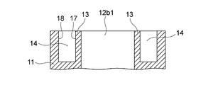
- FIG. 2 is an end view taken along line xx of FIG. It is a perspective view of the cylinder block shown in FIG. It is a typical perspective view which shows the example of a form of the water jacket spacer of this invention. It is the top view which looked at the water jacket spacer shown in FIG. 4 from the upper side.
- FIG. 6 is an end view taken along line yy of FIG. 5. It is a schematic diagram which shows a mode that the water jacket spacer shown in FIG. 4 is inserted in the cylinder block shown in FIG. It is a schematic diagram which shows a mode that the water jacket spacer shown in FIG.
- FIG. 4 is installed in the groove-shaped cooling water flow path of the cylinder block shown in FIG. It is the figure which looked at the inside of a groove-shaped cooling water flow path from the wall surface side by the side of a cylinder bore in the state where the water jacket spacer was installed in the groove-shaped cooling water flow path. It is an end view of the state in which the water jacket spacer is installed in the grooved cooling water flow path. It is a top view which shows the example of a form of a main-body part. It is a schematic diagram which shows the example of a form of an outer side contact member. It is a schematic diagram which shows the example of a form of an inner side contact member. It is a schematic diagram which shows the example of an inner side contact member and an outer side contact member.
- FIGS. 1 to 3 show an example of a cylinder block in which the water jacket spacer of the present invention is installed
- FIG. 1 is a schematic plan view showing the cylinder block in which the water jacket spacer of the present invention is installed.
- FIG. 2 is an end view taken along line xx of FIG. 1
- FIG. 3 is a perspective view of the cylinder block shown in FIG. 4 to 6 show an example of the form of the water jacket spacer of the present invention
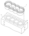
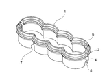
- FIG. 4 is a schematic perspective view showing an example of the form of the water jacket spacer of the present invention
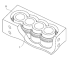
- FIG. 4 is a plan view of the water jacket spacer shown in FIG. 4 as viewed from above, and FIG. 6 is an end view taken along the line yy of the water jacket spacer shown in FIG. 7 is a schematic view showing how the water jacket spacer shown in FIG. 4 is inserted into the cylinder block shown in FIG. 2, and FIG. 8 shows the groove of the cylinder block shown in FIG. 2 in the water jacket spacer shown in FIG.
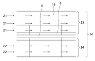
- FIG. 9 is a schematic view showing a state in which the water jacket spacer is installed in the grooved cooling water flow channel, and the inside of the grooved cooling water flow channel is arranged on the cylinder bore side.
- FIG. 10 is an end view of a state in which the water jacket spacer is installed in the groove-shaped cooling water flow path.
- an open deck type cylinder block 11 of a vehicle-mounted internal combustion engine in which a water jacket spacer is installed has a bore 12 for moving a piston up and down, and a groove for flowing cooling water.
- a cooling water flow path 14 is formed.
- a wall that separates the bore 12 and the grooved coolant flow path 14 is a cylinder bore wall 13.
- the cylinder block 11 has cooling water supply ports 15a and 15b for supplying cooling water to the grooved cooling water flow path 14 and cooling water discharge ports 16a for discharging the cooling water from the grooved cooling water flow path 11. 16b is formed.
- the cooling water supply port 15 a is a supply port for supplying cooling water to the upper partition flow channel of the groove-shaped cooling water flow channel 14, and the cooling water supply port 15 b is a lower partition of the groove-shaped cooling water flow channel 14.
- the cooling water discharge port 16a is a supply port for supplying cooling water to the flow channel, and the cooling water discharge port 16a is a discharge port for discharging cooling water from the upper partition flow channel of the grooved cooling water flow channel 14.
- the outlet 16b is a discharge port for discharging cooling water from the partition flow path below the grooved cooling water flow path 14.
- the cylinder block 11 is formed so that two or more bores 12 are arranged in series. Therefore, the bore 12 has end bores 12a1 and 12a2 adjacent to one bore and intermediate bores 12b1 and 12b2 sandwiched between the two bores (note that the number of bores in the cylinder block is two). In the case, only the end bore.) Of the bores arranged in series, the end bores 12a1 and 12a2 are bores at both ends, and the intermediate bores 12b1 and 12b2 are bores between the end bore 12a1 at one end and the end bore 12a2 at the other end.
- the wall surface on the cylinder bore 13 side is described as the wall surface 17 on the cylinder bore side of the grooved cooling water flow path, and among the wall surfaces of the grooved cooling water flow path 14,
- the wall surface on the opposite side to the wall surface 17 on the cylinder bore side of the grooved cooling water channel is referred to as the outer wall surface 18 of the grooved cooling water channel.
- the water jacket spacer 1 shown in FIGS. 4 to 6 includes a main body 2, an inner wall side contact member 6, and an outer wall side contact member 4.
- the main body 2 is a member that is disposed in the middle and lower part of the groove-shaped cooling water flow path 14 and fills the gap in the center and the vicinity in the width direction of the middle and lower part of the groove-shaped cooling water flow path.
- the shape of the main body 2 is a shape that follows the shape of the groove-shaped cooling water channel 14 when viewed from above. In other words, the main body 2 has a shape surrounding the wall surface 17 on the cylinder bore side of the groove-like cooling water flow path 14 when viewed from above.
- the inner wall side abutting member 6 has a longitudinal direction (lateral direction) of the inner wall of the main body 2 so as to surround the wall surface 17 on the cylinder bore side of the grooved cooling water channel 14 when the grooved cooling water channel 14 is installed. Attached.
- the inner wall side abutting member 6 is fitted in an inner wall side abutting member fitting portion 5 formed on the inner wall side of the main body portion 2 and attached to the inner wall side of the main body portion 2.
- the outer wall side contact member 4 is attached over the longitudinal direction (lateral direction) of the outer wall of the main body 2 so as to surround the main body 2.
- the outer wall side abutting member 4 is fitted into an outer wall side abutting member fitting portion 3 formed on the outer wall side of the main body portion 2 and attached to the outer wall side of the main body portion 2.
- cooling water is passed between the main body 2 and the wall surface on the cylinder bore side of the grooved cooling water flow path.
- An inner inflow hole 7 for flowing into the cooling water flow path is formed, and below the position in the height direction of the inner wall side contact member 4 and the outer wall side contact member 6 of the main body 2, To flow out from the cooling water flow path between the main body 2 and the wall surface on the cylinder bore side of the grooved cooling water flow path to the cooling water flow path between the main body 2 and the outer wall surface of the grooved cooling water flow path.
- An outer outflow hole 8 is formed.
- the water jacket spacer 1 is inserted into the grooved cooling water flow path 14 of the cylinder block 11 and installed in the grooved cooling water flow path 14 as shown in FIGS.
- FIG. 9 only the outer wall surface of the main body portion, the inner wall side abutting member, and the grooved cooling water flow path is shown.
- the inner wall side abutting member 6 abuts on the cylinder bore side wall surface 17 of the grooved cooling water flow path 14, and the outer wall side abutting member 4 abuts on the outer wall surface 18 of the grooved cooling water flow path 14.
- the groove-shaped cooling water flow path 14 is partitioned into a partition flow path 23 on the upper side of the groove-shaped cooling water flow path and a partition flow path 24 on the lower side of the groove-shaped cooling water flow path. Therefore, a pump for supplying the cooling water 21 to the upper partition flow path 23 of the groove-shaped cooling water flow path and a pump for supplying the cooling water 22 to the lower partition flow path 24 of the groove-shaped cooling water flow path are provided.
- the flow rate of the cooling water between the upper partition channel 23 of the grooved coolant channel and the lower partition channel 24 of the grooved coolant channel can be made different, and the groove The flow rate of the cooling water in the partition channel 23 on the upper side of the cooling water channel and the flow rate of the cooling water in the partition channel 24 on the lower side of the grooved cooling water channel can be adjusted separately.
- the water jacket spacer of the present invention is a water jacket spacer that is inserted into a groove-like cooling water flow path of a cylinder block of an internal combustion engine, A main body having a shape along the groove-shaped cooling water flow path; A groove-shaped cooling water flow path that is attached to the inner wall side of the main body section in the longitudinal direction of the inner wall of the main body section and that is in contact with the wall surface of the groove-shaped cooling water flow path on the cylinder bore side.
- the forms of the water jacket spacer of the present invention include the forms shown below.
- the water jacket spacer of the first aspect of the present invention is a water jacket spacer that is inserted into a groove-like cooling water flow path of a cylinder block of an internal combustion engine, A main body having a shape along the entire circumference of the grooved cooling water flow path; A groove on the inner wall side of the main body portion is provided over the entire length of the inner wall of the main body portion, and comes into contact with the wall surface on the cylinder bore side of the groove-shaped cooling water flow path, thereby providing a groove inside the water jacket spacer.
- An inner wall side abutting member for partitioning the cooling water flow path vertically A groove shape outside the water jacket spacer is provided on the outer wall side of the main body portion over the entire length of the outer wall of the main body portion, and comes into contact with the outer wall surface of the groove-shaped cooling water flow path.
- the water jacket spacer of the second aspect of the present invention is a water jacket spacer inserted into the groove-like cooling water flow path of the cylinder block of the internal combustion engine, A main body having a shape along the entire circumference of the grooved cooling water flow path; A groove on the inner wall side of the main body portion is provided over the entire length of the inner wall of the main body portion, and comes into contact with the wall surface on the cylinder bore side of the groove-shaped cooling water flow path, thereby providing a groove inside the water jacket spacer.
- An inner wall side abutting member for partitioning the cooling water flow path vertically, Having It is a water jacket spacer.
- the water jacket spacer of the third aspect of the present invention is a water jacket spacer inserted into the groove-like cooling water flow path of the cylinder block of the internal combustion engine, A main body having a shape along the entire circumference of the grooved cooling water flow path; A groove shape outside the water jacket spacer is provided on the outer wall side of the main body portion over the entire length of the outer wall of the main body portion, and comes into contact with the outer wall surface of the groove-shaped cooling water flow path.
- a water jacket spacer is a water jacket spacer inserted into a groove-like cooling water flow path of a cylinder block of an internal combustion engine, A main body having a shape along the entire circumference of the grooved cooling water flow path; Grooved cooling on the inner wall side of the main body is attached to a part of the inner wall of the main body in the longitudinal direction.
- a groove-shaped cooling water flow outside the water jacket spacer is attached to a part of the outer wall of the main body on the outer wall side of the main body, and abuts against a wall surface outside the groove-shaped cooling water flow path.
- a water jacket spacer is a water jacket spacer inserted into a grooved cooling water flow path of a cylinder block of an internal combustion engine, A main body having a shape along a part of the entire flow path of the grooved cooling water flow path; A groove on the inner wall side of the main body portion is provided over the entire length of the inner wall of the main body portion, and comes into contact with the wall surface on the cylinder bore side of the groove-shaped cooling water flow path, thereby providing a groove inside the water jacket spacer.
- An inner wall side abutting member for partitioning the cooling water flow path vertically A groove shape outside the water jacket spacer is provided on the outer wall side of the main body portion over the entire length of the outer wall of the main body portion, and comes into contact with the outer wall surface of the groove-shaped cooling water flow path.
- the water jacket spacer of the sixth aspect of the present invention is a water jacket spacer that is inserted into the groove-like cooling water flow path of the cylinder block of the internal combustion engine, A main body having a shape along a part of the entire flow path of the grooved cooling water flow path; A groove on the inner wall side of the main body portion is provided over the entire length of the inner wall of the main body portion, and comes into contact with the wall surface on the cylinder bore side of the groove-shaped cooling water flow path, thereby providing a groove inside the water jacket spacer.
- An inner wall side abutting member for partitioning the cooling water flow path vertically, Having It is a water jacket spacer.
- the water jacket spacer of the seventh aspect of the present invention is a water jacket spacer inserted into the grooved cooling water flow path of the cylinder block of the internal combustion engine, A main body having a shape along a part of the entire flow path of the grooved cooling water flow path; A groove shape outside the water jacket spacer is provided on the outer wall side of the main body portion over the entire length of the outer wall of the main body portion, and comes into contact with the outer wall surface of the groove-shaped cooling water flow path.
- the water jacket spacer of the eighth form of the present invention is a water jacket spacer inserted into the grooved cooling water flow path of the cylinder block of the internal combustion engine, A main body having a shape along a part of the entire flow path of the grooved cooling water flow path; Grooved cooling on the inner wall side of the main body is attached to a part of the inner wall of the main body in the longitudinal direction.
- a groove-shaped cooling water flow outside the water jacket spacer is attached to a part of the outer wall of the main body on the outer wall side of the main body, and abuts against a wall surface outside the groove-shaped cooling water flow path.
- the main body is a member that fills the gap in the center and the vicinity in the width direction of the middle lower part or the lower part of the grooved cooling water flow path when arranged in the middle lower part or the lower part of the grooved cooling water flow path. Then, the main body portion has an inner wall side contact in the grooved cooling water flow path so that the position of the inner wall side contact member or the outer wall side contact member in the grooved cooling water flow path is fixed at a predetermined position. It is also a member for supporting the contact member or the outer wall side contact member. Therefore, the shape of the main body portion is a shape that follows the shape of the groove-shaped cooling water flow channel when viewed from above, and is a shape that extends along a part or all of the entire flow channel of the groove-shaped cooling water flow channel.
- the shape of the main body is a shape that surrounds all the wall surfaces on the cylinder bore side of the grooved cooling water flow path, but in the grooved cooling water flow path of the inner wall side contact member and the outer wall side contact member.
- the inner wall side abutting member or the outer wall side abutting member can be supported so that the position at is fixed at a predetermined position, and the cooling water flow rate and lower side of the partition channel above the grooved cooling water channel If it is the shape which can adjust separately the cooling water flow rate of this division flow path, it will not be restrict
- the shape of the main body does not surround the entire wall surface on the cylinder bore side of the grooved cooling water flow path, but a shape in which a part in the longitudinal direction is missing as in the embodiment shown in FIG. Even if the shape is along a part of the entire flow path of the groove-shaped cooling water flow path, by supporting the inner wall-side contact member and the outer wall-side contact member, the partition flow path on the upper side of the groove-shaped cooling water flow path What is necessary is just to be able to partition so that the cooling water flow rate and the cooling water flow rate of the lower partition channel can be adjusted substantially separately.
- an inner inflow hole is formed for flowing the cooling water into the cooling water flow path between the main body and the wall surface on the cylinder bore side of the grooved cooling water flow path.
- the holes are formed, the cooling water flows into the cooling water flow path between the main body and the wall surface of the grooved cooling water flow path on the cylinder bore side, and the wall surface of the main body and the grooved cooling water flow path on the cylinder bore side If it can flow out from the cooling water flow path between the two, there is no particular limitation.
- a shape in which a part of a portion below the height direction position of the inner wall side contact member or the outer wall side contact member is notched, the height of the inner wall side contact member or the outer wall side contact member examples include a shape in which only a part below the position in the direction is present.
- the height of the main body is determined so that the position of the inner wall side contact member or the outer wall side contact member in the grooved coolant flow path is fixed at a predetermined position. There is no particular limitation as long as the member can be supported. In the embodiment shown in FIG. 4, the height of the main body is constant in the longitudinal direction, but is not limited to this, and there may be portions having different heights.
- the material of the main body is not particularly limited as long as it has good long-life coolant resistance (hereinafter referred to as “LLC resistance”) and has heat resistance to withstand the temperature in the grooved cooling water flow path.
- LLC resistance long-life coolant resistance
- polyethylene polytetrafluoroethylene, polypropylene, polystyrene, acrylotolyl, butanediene, styrene resin, polyvinyl chloride, acrylonitrile, styrene resin, methacrylic resin, vinyl chloride, polyamide, polyacetal, polycarbonate, modified polyphenylene ether, polybutylene terephthalate , GF reinforced polyethylene terephthalate, ultra high molecular weight polyethylene, polyphenylene sulfide, polyimide, polyetherimide, polyarylate, polysulfone, polyethersulfone, polyetheretherketone, liquid crystal poly -Thermoplastic resins such as polyethylene, polyethylene ter
- the inner wall side abutting member When the inner wall side abutting member is installed in the grooved cooling water flow path, the inner wall side abutting member abuts against the wall surface on the cylinder bore side of the grooved cooling water flow path, or over the entire longitudinal direction (lateral direction) of the inner wall of the main body part or It is attached to a part in the longitudinal direction. Further, the outer wall side abutting member is attached to the entire longitudinal direction (lateral direction) of the outer wall of the main body or a part of the longitudinal direction.
- the water jacket spacer is installed in the groove-shaped cooling water flow path, the inner wall-side contact member is in contact with the wall surface on the cylinder bore side of the groove-shaped cooling water flow path, and the outer wall-side contact member is in the groove-shaped cooling water flow path. By contacting the outer wall surface of the path, the grooved cooling water flow path is partitioned into an upper partition flow path and a lower partition flow path.
- both the inner wall side abutting member and the outer wall side abutting member are connected without interruption in the longitudinal direction of the main body, but the present invention is not limited to this.
- the cooling water flow rate of the upper partition channel and the lower partition channel of the grooved cooling water channel What is necessary is just to be able to partition so that a cooling water flow volume can be adjusted substantially separately.
- the inner wall side contact member or the outer wall side contact member is formed on the inner wall side or the outer wall side of the main body. It is attached to the inner wall side or the outer wall side of the main body portion by being fitted into the fitting portion, but is not limited to this, and the inner wall side contact member or the outer wall side contact member is attached to the main body portion. Any method can be used.
- the thickness of the inner wall side contact member or the outer wall side contact member is not particularly limited, but is preferably 0.1 to 5.0 mm, particularly preferably 0.5 to 3. 0.0 mm. Further, the length from the contact portion of the inner wall side contact member to the contact portion of the outer wall side contact member (the length indicated by reference numeral 26 in FIG. 6) is appropriately selected according to the grooved cooling water flow path.
- the material of the inner wall side abutting member or the outer wall side abutting member can abut against the wall surface on the cylinder bore side or the outer wall surface of the grooved cooling water flow path so that the grooved cooling water flow path can be substantially divided into upper and lower partition flow paths.
- the inner wall side contact member and the outer wall side contact member are preferably made of a rubber material having a rubber hardness of 5 to 50 degrees, and particularly preferably made of a rubber material having a rubber hardness of 10 to 30 degrees.
- Examples of the material of the inner wall side contact member or the outer wall side contact member include silicon rubber, fluorine rubber, natural rubber, butadiene rubber, ethylene propylene diene rubber (EPDM), and nitrile butadiene rubber (NBR).
- Thermally-expandable rubbers such as rubber, fluorine rubber, natural rubber, butadiene rubber, ethylene propylene diene rubber (EPDM) and nitrile butadiene rubber (NBR) are preferred.
- Thermally-expandable rubber is a composite in which a base foam material is impregnated with a thermoplastic material having a melting point lower than that of the base foam material and is compressed. In addition, the cured material of the thermoplastic material is softened by heating, and the compressed state is released.
- the water jacket spacer of the present invention is installed in the grooved cooling water flow path, and heat is applied to the heat-sensitive expansion rubber.
- the heat-sensitive expansion rubber expands and expands and deforms into a predetermined shape.
- the base foam material related to the heat-expandable rubber include silicon rubber, fluorine rubber, natural rubber, butadiene rubber, ethylene propylene diene rubber (EPDM), and nitrile butadiene rubber (NBR).
- the thermoplastic substance related to the heat-sensitive expansion rubber those having any of glass transition point, melting point or softening temperature of less than 120 ° C are preferable.
- Thermoplastic materials related to heat-expandable rubber include polyethylene, polypropylene, polystyrene, polyvinyl chloride, polyvinylidene chloride, polyvinyl acetate, polyacrylate ester, styrene butadiene copolymer, chlorinated polyethylene, polyvinylidene fluoride, ethylene acetate Vinyl copolymer, ethylene vinyl acetate vinyl chloride acrylic ester copolymer, ethylene vinyl acetate acrylic ester copolymer, ethylene vinyl acetate vinyl chloride copolymer, nylon, acrylonitrile butadiene copolymer, polyacrylonitrile, polyvinyl chloride , Polychloroprene, polybutadiene, thermoplastic polyimide, polyacetal, polyphenylene sulfide, polycarbonate, thermoplastic resins such as thermoplastic polyurethane, low melting glass frit, starch Solder include various thermoplastic compounds such as wax.
- the inner wall-side contact member or the outer wall-side contact member has a constant position in the height direction of the main body, but is limited to this. is not.
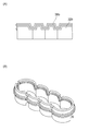
- the outer wall side contact member 34a is attached to the outer wall surface of the main body 32a so that the position in the height direction changes over the entire length of the main body.
- the inner wall side abutting member 36b is disposed on the main body portion so that a part of the main body portion in the longitudinal direction is different from the other portions in the height direction. It may be attached to the outer wall surface of 32b.
- the height direction positions of the inner wall side abutting member and the outer wall side abutting member are the same throughout the longitudinal direction of the main body, but this is not restrictive. .
- the inner wall side abutting member 36c is positioned higher in the height direction than the outer wall side abutting member 34c in the height direction.
- the contact member 36c and the outer wall side contact member 34c may be attached to the main body 32c, and the height direction of the inner wall side contact member 36d as in the embodiment shown in FIG.
- the inner wall side contact member 36d and the outer wall side contact member 34d may be attached to the main body portion 32d so that the position of the inner wall side contact member 34d is lower than the position in the height direction of the outer wall side contact member 34d.
- the water jacket spacer of the present invention is installed in the grooved cooling water flow path, and the inner wall side abutting member abuts on the wall surface on the cylinder bore side of the grooved cooling water flow path, or the outer wall side abutting member is in the grooved cooling water flow Since the grooved cooling water flow path inside the water jacket spacer or outside the water jacket spacer is partitioned into an upper partition flow path and a lower partition flow path by abutting against the outer wall surface of the path.
- the flow rate of the cooling water in the upper partition channel and the flow rate of the cooling water in the lower partition channel can be controlled separately and at desired flow rates, respectively.
- the upper and lower partition channels of the grooved cooling water channel are made uniform so that the upper and lower temperatures of the cylinder bore wall become uniform.
- the flow rate of the cooling water and the flow rate of the cooling water in the lower partition channel can be adjusted respectively. For this reason, according to the water jacket spacer of the present invention, the uniformity of the wall temperature of the cylinder bore wall can be increased.
- the internal combustion engine of the present invention is an internal combustion engine characterized in that the water jacket spacer of the present invention is installed in a grooved cooling water flow path of a cylinder block. Further, an automobile of the present invention is an automobile having the internal combustion engine of the present invention.
- the difference in deformation amount between the upper side and the lower side of the cylinder bore wall of the internal combustion engine can be reduced, and the friction of the piston can be reduced, so that a fuel-saving internal combustion engine can be provided.
Landscapes
- Engineering & Computer Science (AREA)
- Chemical & Material Sciences (AREA)
- Combustion & Propulsion (AREA)
- Mechanical Engineering (AREA)
- General Engineering & Computer Science (AREA)
- Cylinder Crankcases Of Internal Combustion Engines (AREA)
Abstract
Description
該溝状冷却水流路に沿った形状を有する本体部と、
該本体部の内壁側に該本体部の内壁の長手方向に付設されており、該溝状冷却水流路のシリンダボア側の壁面に当接することにより、該ウォータージャケットスペーサーより内側の溝状冷却水流路を上下に区画するための内壁側当接部材、及び該本体部の外壁側に該本体部の外壁の長手方向に付設されており、該溝状冷却水流路の外側の壁面に当接することにより、該ウォータージャケットスペーサーより外側の溝状冷却水流路を上下に区画するための外壁側当接部材のうちのいずれか一方又は両方と、
を有すること、
を特徴とするウォータージャケットスペーサーを提供するものである。
該溝状冷却水流路に沿った形状を有する本体部と、
該本体部の内壁側に該本体部の内壁の長手方向に付設されており、該溝状冷却水流路のシリンダボア側の壁面に当接することにより、該ウォータージャケットスペーサーより内側の溝状冷却水流路を上下に区画するための内壁側当接部材、及び該本体部の外壁側に該本体部の外壁の長手方向に付設されており、該溝状冷却水流路の外側の壁面に当接することにより、該ウォータージャケットスペーサーより外側の溝状冷却水流路を上下に区画するための外壁側当接部材のうちのいずれか一方又は両方と、
を有すること、
を特徴とするウォータージャケットスペーサーである。
該溝状冷却水流路の全周に沿った形状を有する本体部と、
該本体部の内壁側に該本体部の内壁の長手方向の全体に亘って付設されており、該溝状冷却水流路のシリンダボア側の壁面に当接することにより、該ウォータージャケットスペーサーより内側の溝状冷却水流路を上下に区画するための内壁側当接部材と、
該本体部の外壁側に該本体部の外壁の長手方向の全体に亘って付設されており、該溝状冷却水流路の外側の壁面に当接することにより、該ウォータージャケットスペーサーより外側の溝状冷却水流路を上下に区画するための外壁側当接部材と、
を有すること、
特徴とするウォータージャケットスペーサーである。
該溝状冷却水流路の全周に沿った形状を有する本体部と、
該本体部の内壁側に該本体部の内壁の長手方向の全体に亘って付設されており、該溝状冷却水流路のシリンダボア側の壁面に当接することにより、該ウォータージャケットスペーサーより内側の溝状冷却水流路を上下に区画するための内壁側当接部材と、
を有すること、
特徴とするウォータージャケットスペーサーである。
該溝状冷却水流路の全周に沿った形状を有する本体部と、
該本体部の外壁側に該本体部の外壁の長手方向の全体に亘って付設されており、該溝状冷却水流路の外側の壁面に当接することにより、該ウォータージャケットスペーサーより外側の溝状冷却水流路を上下に区画するための外壁側当接部材と、
を有すること、
特徴とするウォータージャケットスペーサーである。
該溝状冷却水流路の全周に沿った形状を有する本体部と、
該本体部の内壁側に該本体部の内壁の長手方向の一部分に付設されており、該溝状冷却水流路のシリンダボア側の壁面に当接することにより、該ウォータージャケットスペーサーより内側の溝状冷却水流路を上下に区画するための内壁側当接部材と、
該本体部の外壁側に該本体部の外壁の長手方向の一部分に付設されており、該溝状冷却水流路の外側の壁面に当接することにより、該ウォータージャケットスペーサーより外側の溝状冷却水流路を上下に区画するための外壁側当接部材と、
を有すること、
特徴とするウォータージャケットスペーサーである。
該溝状冷却水流路の全流路のうちの一部分に沿った形状を有する本体部と、
該本体部の内壁側に該本体部の内壁の長手方向の全体に亘って付設されており、該溝状冷却水流路のシリンダボア側の壁面に当接することにより、該ウォータージャケットスペーサーより内側の溝状冷却水流路を上下に区画するための内壁側当接部材と、
該本体部の外壁側に該本体部の外壁の長手方向の全体に亘って付設されており、該溝状冷却水流路の外側の壁面に当接することにより、該ウォータージャケットスペーサーより外側の溝状冷却水流路を上下に区画するための外壁側当接部材と、
を有すること、
特徴とするウォータージャケットスペーサーである。
該溝状冷却水流路の全流路のうちの一部分に沿った形状を有する本体部と、
該本体部の内壁側に該本体部の内壁の長手方向の全体に亘って付設されており、該溝状冷却水流路のシリンダボア側の壁面に当接することにより、該ウォータージャケットスペーサーより内側の溝状冷却水流路を上下に区画するための内壁側当接部材と、
を有すること、
特徴とするウォータージャケットスペーサーである。
該溝状冷却水流路の全流路のうちの一部分に沿った形状を有する本体部と、
該本体部の外壁側に該本体部の外壁の長手方向の全体に亘って付設されており、該溝状冷却水流路の外側の壁面に当接することにより、該ウォータージャケットスペーサーより外側の溝状冷却水流路を上下に区画するための外壁側当接部材と、
を有すること、
特徴とするウォータージャケットスペーサーである。
該溝状冷却水流路の全流路のうちの一部分に沿った形状を有する本体部と、
該本体部の内壁側に該本体部の内壁の長手方向の一部分に付設されており、該溝状冷却水流路のシリンダボア側の壁面に当接することにより、該ウォータージャケットスペーサーより内側の溝状冷却水流路を上下に区画するための内壁側当接部材と、
該本体部の外壁側に該本体部の外壁の長手方向の一部分に付設されており、該溝状冷却水流路の外側の壁面に当接することにより、該ウォータージャケットスペーサーより外側の溝状冷却水流路を上下に区画するための外壁側当接部材と、
を有すること、
特徴とするウォータージャケットスペーサーである。
2、32a、32b、32c、32d 本体部
3 外壁側当接部材嵌め込み部
4、34a、34c、34d 外壁側当接部材
5 内壁側当接部材嵌め込み部
6、36b、36c、36d 内壁側当接部材
7 内側流入用穴
11 シリンダブロック
12 ボア
13 シリンダボア壁
14 溝状冷却水流路
15a、15b 冷却水供給口
16a、16b 冷却水排出口
17 溝状冷却水流路のシリンダボア側の壁面
18 溝状冷却水流路の外側の壁面
23 溝状冷却水流路の上側の区画流路
24 溝状冷却水流路の下側の区画流路
Claims (15)
- 内燃機関のシリンダブロックの溝状冷却水流路内に挿入されるウォータージャケットスペーサーであって、
該溝状冷却水流路に沿った形状を有する本体部と、
該本体部の内壁側に該本体部の内壁の長手方向に付設されており、該溝状冷却水流路のシリンダボア側の壁面に当接することにより、該ウォータージャケットスペーサーより内側の溝状冷却水流路を上下に区画するための内壁側当接部材、及び該本体部の外壁側に該本体部の外壁の長手方向に付設されており、該溝状冷却水流路の外側の壁面に当接することにより、該ウォータージャケットスペーサーより外側の溝状冷却水流路を上下に区画するための外壁側当接部材のうちのいずれか一方又は両方と、
を有すること、
を特徴とするウォータージャケットスペーサー。 - 内燃機関のシリンダブロックの溝状冷却水流路内に挿入されるウォータージャケットスペーサーであって、
該溝状冷却水流路の全周に沿った形状を有する本体部と、
該本体部の内壁側に該本体部の内壁の長手方向の全体に亘って付設されており、該溝状冷却水流路のシリンダボア側の壁面に当接することにより、該ウォータージャケットスペーサーより内側の溝状冷却水流路を上下に区画するための内壁側当接部材と、
該本体部の外壁側に該本体部の外壁の長手方向の全体に亘って付設されており、該溝状冷却水流路の外側の壁面に当接することにより、該ウォータージャケットスペーサーより外側の溝状冷却水流路を上下に区画するための外壁側当接部材と、
を有すること、
特徴とする請求項1記載のウォータージャケットスペーサー。 - 内燃機関のシリンダブロックの溝状冷却水流路内に挿入されるウォータージャケットスペーサーであって、
該溝状冷却水流路の全周に沿った形状を有する本体部と、
該本体部の内壁側に該本体部の内壁の長手方向の全体に亘って付設されており、該溝状冷却水流路のシリンダボア側の壁面に当接することにより、該ウォータージャケットスペーサーより内側の溝状冷却水流路を上下に区画するための内壁側当接部材と、
を有すること、
特徴とする請求項1記載のウォータージャケットスペーサー。 - 内燃機関のシリンダブロックの溝状冷却水流路内に挿入されるウォータージャケットスペーサーであって、
該溝状冷却水流路の全周に沿った形状を有する本体部と、
該本体部の外壁側に該本体部の外壁の長手方向の全体に亘って付設されており、該溝状冷却水流路の外側の壁面に当接することにより、該ウォータージャケットスペーサーより外側の溝状冷却水流路を上下に区画するための外壁側当接部材と、
を有すること、
特徴とする請求項1記載のウォータージャケットスペーサー。 - 内燃機関のシリンダブロックの溝状冷却水流路内に挿入されるウォータージャケットスペーサーであって、
該溝状冷却水流路の全周に沿った形状を有する本体部と、
該本体部の内壁側に該本体部の内壁の長手方向の一部分に付設されており、該溝状冷却水流路のシリンダボア側の壁面に当接することにより、該ウォータージャケットスペーサーより内側の溝状冷却水流路を上下に区画するための内壁側当接部材と、
該本体部の外壁側に該本体部の外壁の長手方向の一部分に付設されており、該溝状冷却水流路の外側の壁面に当接することにより、該ウォータージャケットスペーサーより外側の溝状冷却水流路を上下に区画するための外壁側当接部材と、
を有すること、
特徴とする請求項1記載のウォータージャケットスペーサー。 - 内燃機関のシリンダブロックの溝状冷却水流路内に挿入されるウォータージャケットスペーサーであって、
該溝状冷却水流路の全流路のうちの一部分に沿った形状を有する本体部と、
該本体部の内壁側に該本体部の内壁の長手方向の全体に亘って付設されており、該溝状冷却水流路のシリンダボア側の壁面に当接することにより、該ウォータージャケットスペーサーより内側の溝状冷却水流路を上下に区画するための内壁側当接部材と、
該本体部の外壁側に該本体部の外壁の長手方向の全体に亘って付設されており、該溝状冷却水流路の外側の壁面に当接することにより、該ウォータージャケットスペーサーより外側の溝状冷却水流路を上下に区画するための外壁側当接部材と、
を有すること、
特徴とする請求項1記載のウォータージャケットスペーサー。 - 内燃機関のシリンダブロックの溝状冷却水流路内に挿入されるウォータージャケットスペーサーであって、
該溝状冷却水流路の全流路のうちの一部分に沿った形状を有する本体部と、
該本体部の内壁側に該本体部の内壁の長手方向の全体に亘って付設されており、該溝状冷却水流路のシリンダボア側の壁面に当接することにより、該ウォータージャケットスペーサーより内側の溝状冷却水流路を上下に区画するための内壁側当接部材と、
を有すること、
特徴とする請求項1記載のウォータージャケットスペーサー。 - 内燃機関のシリンダブロックの溝状冷却水流路内に挿入されるウォータージャケットスペーサーであって、
該溝状冷却水流路の全流路のうちの一部分に沿った形状を有する本体部と、
該本体部の外壁側に該本体部の外壁の長手方向の全体に亘って付設されており、該溝状冷却水流路の外側の壁面に当接することにより、該ウォータージャケットスペーサーより外側の溝状冷却水流路を上下に区画するための外壁側当接部材と、
を有すること、
特徴とする請求項1記載のウォータージャケットスペーサー。 - 内燃機関のシリンダブロックの溝状冷却水流路内に挿入されるウォータージャケットスペーサーであって、
該溝状冷却水流路の全流路のうちの一部分に沿った形状を有する本体部と、
該本体部の内壁側に該本体部の内壁の長手方向の一部分に付設されており、該溝状冷却水流路のシリンダボア側の壁面に当接することにより、該ウォータージャケットスペーサーより内側の溝状冷却水流路を上下に区画するための内壁側当接部材と、
該本体部の外壁側に該本体部の外壁の長手方向の一部分に付設されており、該溝状冷却水流路の外側の壁面に当接することにより、該ウォータージャケットスペーサーより外側の溝状冷却水流路を上下に区画するための外壁側当接部材と、
を有すること、
特徴とする請求項1記載のウォータージャケットスペーサー。 - 前記内壁側当接部材の厚み又は前外壁側当接部材の厚みが、0.1~5.0mmであることを特徴とする請求項1項記載のウォータージャケットスペーサー。
- 前記内壁側当接部材又は前記外壁側当接部材が、ゴム硬度が5~50度のゴム材からなることを特徴とする請求項1記載のウォータージャケットスペーサー。
- 前記内壁側当接部材又は前記外壁側当接部材が、シリコンゴム、フッ素ゴム、エチレンプロピレンジエンゴム(EPDM)又はニトリルブタジエンゴム(NBR)からなることを特徴とする請求項1記載のウォータージャケットスペーサー。
- 前記内壁側当接部材又は前記外壁側当接部材が、シリコンゴム、フッ素ゴム、エチレンプロピレンジエンゴム(EPDM)及びニトリルブタジエンゴム(NBR)のうちいずれかの感熱膨張ゴムからなることを特徴とする請求項12記載のウォータージャケットスペーサー。
- シリンダブロックの溝状冷却水流路内に、請求項1~13いずれか1項記載のウォータージャケットスペーサーが設置されていることを特徴とする内燃機関。
- 請求項14記載の内燃機関を有することを特徴とする自動車。
Priority Applications (3)
| Application Number | Priority Date | Filing Date | Title |
|---|---|---|---|
| JP2016566358A JP6533531B2 (ja) | 2014-12-22 | 2015-12-21 | ウォータージャケットスペーサー、内燃機関及び自動車 |
| US15/538,300 US20170350302A1 (en) | 2014-12-22 | 2015-12-21 | Water jacket spacer, internal combustion engine, and automobile |
| EP15873011.9A EP3239507B1 (en) | 2014-12-22 | 2015-12-21 | Water jacket spacer, internal combustion engine, and automobile |
Applications Claiming Priority (2)
| Application Number | Priority Date | Filing Date | Title |
|---|---|---|---|
| JP2014258313 | 2014-12-22 | ||
| JP2014-258313 | 2014-12-22 |
Publications (1)
| Publication Number | Publication Date |
|---|---|
| WO2016104443A1 true WO2016104443A1 (ja) | 2016-06-30 |
Family
ID=56150462
Family Applications (1)
| Application Number | Title | Priority Date | Filing Date |
|---|---|---|---|
| PCT/JP2015/085708 Ceased WO2016104443A1 (ja) | 2014-12-22 | 2015-12-21 | ウォータージャケットスペーサー、内燃機関及び自動車 |
Country Status (4)
| Country | Link |
|---|---|
| US (1) | US20170350302A1 (ja) |
| EP (1) | EP3239507B1 (ja) |
| JP (1) | JP6533531B2 (ja) |
| WO (1) | WO2016104443A1 (ja) |
Cited By (1)
| Publication number | Priority date | Publication date | Assignee | Title |
|---|---|---|---|---|
| AT15665U1 (de) * | 2016-08-29 | 2018-04-15 | Avl List Gmbh | Kühlungsstruktur für eine Brennkraftmaschine |
Families Citing this family (10)
| Publication number | Priority date | Publication date | Assignee | Title |
|---|---|---|---|---|
| JP6283010B2 (ja) * | 2015-11-12 | 2018-02-21 | ニチアス株式会社 | シリンダボア壁の保温具、内燃機関及び自動車 |
| US10221752B2 (en) * | 2016-04-20 | 2019-03-05 | Hyundai Motor Company | Split cooling apparatus for internal combustion engine |
| KR101795279B1 (ko) * | 2016-06-22 | 2017-11-08 | 현대자동차주식회사 | 내연기관의 분리냉각 시스템 |
| AT521945B1 (de) | 2018-11-30 | 2020-08-15 | Avl List Gmbh | Brennkraftmaschine mit einem Kühlflüssigkeitsmantel |
| JP7238413B2 (ja) | 2019-01-17 | 2023-03-14 | マツダ株式会社 | エンジンの冷却構造 |
| JP7172629B2 (ja) | 2019-01-17 | 2022-11-16 | マツダ株式会社 | エンジンの冷却構造 |
| US10907530B2 (en) * | 2019-05-10 | 2021-02-02 | Ford Global Technologies, Llc | Water jacket diverter and method for operation of an engine cooling system |
| US10876462B1 (en) * | 2019-07-18 | 2020-12-29 | Ford Global Technologies, Llc | Coolant jacket insert |
| AT525164B1 (de) | 2021-10-21 | 2023-01-15 | Avl List Gmbh | Brennkraftmaschine mit einem zylinderblock |
| US11719183B2 (en) | 2021-11-09 | 2023-08-08 | Ford Global Technologies, Llc | Methods and systems for cooling arrangement |
Citations (10)
| Publication number | Priority date | Publication date | Assignee | Title |
|---|---|---|---|---|
| JP2002266695A (ja) * | 2001-03-14 | 2002-09-18 | Toyota Motor Corp | シリンダブロックの冷却構造とその製造方法 |
| JP2004019472A (ja) * | 2002-06-12 | 2004-01-22 | Toyota Motor Corp | シリンダブロック用スペーサ及びシリンダブロック |
| US20050235930A1 (en) * | 2004-04-22 | 2005-10-27 | Honda Motor Co., Ltd. | Cylinder block cooling arrangement for multi-cylinder internal combustion engine |
| JP2005315118A (ja) * | 2004-04-27 | 2005-11-10 | Toyota Motor Corp | シリンダブロックの冷却構造 |
| JP2007309221A (ja) * | 2006-05-18 | 2007-11-29 | Toyota Motor Corp | 内燃機関冷却機構、予備昇温用流路形成方法及び区画部材 |
| JP2008025474A (ja) * | 2006-07-21 | 2008-02-07 | Toyota Motor Corp | 内燃機関冷却用熱媒体流路区画部材、内燃機関冷却構造及び内燃機関冷却構造形成方法 |
| JP2008031939A (ja) * | 2006-07-31 | 2008-02-14 | Toyota Motor Corp | 内燃機関冷却用熱媒体流路区画部材、内燃機関冷却機構及び内燃機関冷却機構形成方法 |
| JP2008128133A (ja) * | 2006-11-22 | 2008-06-05 | Toyota Motor Corp | 内燃機関冷却用熱媒体伝熱調節装置 |
| JP2012202290A (ja) * | 2011-03-25 | 2012-10-22 | Nichias Corp | シリンダボア壁の保温構造体、シリンダボア壁の保温方法、内燃機関及び自動車 |
| JP2015071969A (ja) * | 2013-10-03 | 2015-04-16 | トヨタ自動車株式会社 | 内燃機関 |
Family Cites Families (2)
| Publication number | Priority date | Publication date | Assignee | Title |
|---|---|---|---|---|
| JP4051019B2 (ja) * | 2003-10-17 | 2008-02-20 | トヨタ自動車株式会社 | シリンダブロックの冷却構造 |
| JP5974926B2 (ja) * | 2013-02-21 | 2016-08-23 | マツダ株式会社 | 多気筒エンジンの冷却構造 |
-
2015
- 2015-12-21 WO PCT/JP2015/085708 patent/WO2016104443A1/ja not_active Ceased
- 2015-12-21 US US15/538,300 patent/US20170350302A1/en not_active Abandoned
- 2015-12-21 EP EP15873011.9A patent/EP3239507B1/en active Active
- 2015-12-21 JP JP2016566358A patent/JP6533531B2/ja not_active Expired - Fee Related
Patent Citations (10)
| Publication number | Priority date | Publication date | Assignee | Title |
|---|---|---|---|---|
| JP2002266695A (ja) * | 2001-03-14 | 2002-09-18 | Toyota Motor Corp | シリンダブロックの冷却構造とその製造方法 |
| JP2004019472A (ja) * | 2002-06-12 | 2004-01-22 | Toyota Motor Corp | シリンダブロック用スペーサ及びシリンダブロック |
| US20050235930A1 (en) * | 2004-04-22 | 2005-10-27 | Honda Motor Co., Ltd. | Cylinder block cooling arrangement for multi-cylinder internal combustion engine |
| JP2005315118A (ja) * | 2004-04-27 | 2005-11-10 | Toyota Motor Corp | シリンダブロックの冷却構造 |
| JP2007309221A (ja) * | 2006-05-18 | 2007-11-29 | Toyota Motor Corp | 内燃機関冷却機構、予備昇温用流路形成方法及び区画部材 |
| JP2008025474A (ja) * | 2006-07-21 | 2008-02-07 | Toyota Motor Corp | 内燃機関冷却用熱媒体流路区画部材、内燃機関冷却構造及び内燃機関冷却構造形成方法 |
| JP2008031939A (ja) * | 2006-07-31 | 2008-02-14 | Toyota Motor Corp | 内燃機関冷却用熱媒体流路区画部材、内燃機関冷却機構及び内燃機関冷却機構形成方法 |
| JP2008128133A (ja) * | 2006-11-22 | 2008-06-05 | Toyota Motor Corp | 内燃機関冷却用熱媒体伝熱調節装置 |
| JP2012202290A (ja) * | 2011-03-25 | 2012-10-22 | Nichias Corp | シリンダボア壁の保温構造体、シリンダボア壁の保温方法、内燃機関及び自動車 |
| JP2015071969A (ja) * | 2013-10-03 | 2015-04-16 | トヨタ自動車株式会社 | 内燃機関 |
Non-Patent Citations (1)
| Title |
|---|
| See also references of EP3239507A4 * |
Cited By (1)
| Publication number | Priority date | Publication date | Assignee | Title |
|---|---|---|---|---|
| AT15665U1 (de) * | 2016-08-29 | 2018-04-15 | Avl List Gmbh | Kühlungsstruktur für eine Brennkraftmaschine |
Also Published As
| Publication number | Publication date |
|---|---|
| EP3239507A1 (en) | 2017-11-01 |
| EP3239507B1 (en) | 2020-05-13 |
| EP3239507A4 (en) | 2018-09-26 |
| JPWO2016104443A1 (ja) | 2017-11-30 |
| US20170350302A1 (en) | 2017-12-07 |
| JP6533531B2 (ja) | 2019-06-19 |
Similar Documents
| Publication | Publication Date | Title |
|---|---|---|
| JPWO2016104443A1 (ja) | ウォータージャケットスペーサー、内燃機関及び自動車 | |
| JP6505129B2 (ja) | ウォータージャケットの冷却水流路の区画部品、内燃機関及び自動車 | |
| JP6283011B2 (ja) | シリンダボア壁の保温具、内燃機関及び自動車 | |
| JP6297393B2 (ja) | シリンダボア壁の保温具、内燃機関及び自動車 | |
| KR101901559B1 (ko) | 실린더 보어벽의 보온구, 내연기관 및 자동차 | |
| JP6283010B2 (ja) | シリンダボア壁の保温具、内燃機関及び自動車 | |
| JP5588902B2 (ja) | シリンダボア壁の保温構造体、シリンダボア壁の保温方法、内燃機関及び自動車 | |
| JP2015203313A (ja) | シリンダボア壁の保温具、内燃機関及び自動車 | |
| JP5948268B2 (ja) | シリンダボア壁の保温部材 | |
| JP2017089435A (ja) | シリンダボア壁の保温具、内燃機関及び自動車 | |
| JP6486304B2 (ja) | シリンダボア壁の保温具、内燃機関及び自動車 | |
| US9436189B2 (en) | Thermoregulator | |
| JP5809950B2 (ja) | 複合材料、内燃機関及び自動車 | |
| JP5830049B2 (ja) | シリンダボア壁の保温部材の組み付け方法 | |
| JP2020153247A (ja) | 冷却水流れ制御具、内燃機関及び自動車 | |
| JP6216731B2 (ja) | シリンダボア壁の保温部材、内燃機関及び自動車 |
Legal Events
| Date | Code | Title | Description |
|---|---|---|---|
| 121 | Ep: the epo has been informed by wipo that ep was designated in this application |
Ref document number: 15873011 Country of ref document: EP Kind code of ref document: A1 |
|
| ENP | Entry into the national phase |
Ref document number: 2016566358 Country of ref document: JP Kind code of ref document: A |
|
| WWE | Wipo information: entry into national phase |
Ref document number: 15538300 Country of ref document: US |
|
| NENP | Non-entry into the national phase |
Ref country code: DE |
|
| REEP | Request for entry into the european phase |
Ref document number: 2015873011 Country of ref document: EP |