WO2016104652A1 - 真空ポンプ - Google Patents
真空ポンプ Download PDFInfo
- Publication number
- WO2016104652A1 WO2016104652A1 PCT/JP2015/086112 JP2015086112W WO2016104652A1 WO 2016104652 A1 WO2016104652 A1 WO 2016104652A1 JP 2015086112 W JP2015086112 W JP 2015086112W WO 2016104652 A1 WO2016104652 A1 WO 2016104652A1
- Authority
- WO
- WIPO (PCT)
- Prior art keywords
- cylinder
- vacuum pump
- pump
- inlet
- outlet
- Prior art date
- Legal status (The legal status is an assumption and is not a legal conclusion. Google has not performed a legal analysis and makes no representation as to the accuracy of the status listed.)
- Ceased
Links
Images











Classifications
-
- F—MECHANICAL ENGINEERING; LIGHTING; HEATING; WEAPONS; BLASTING
- F04—POSITIVE - DISPLACEMENT MACHINES FOR LIQUIDS; PUMPS FOR LIQUIDS OR ELASTIC FLUIDS
- F04C—ROTARY-PISTON, OR OSCILLATING-PISTON, POSITIVE-DISPLACEMENT MACHINES FOR LIQUIDS; ROTARY-PISTON, OR OSCILLATING-PISTON, POSITIVE-DISPLACEMENT PUMPS
- F04C18/00—Rotary-piston pumps specially adapted for elastic fluids
- F04C18/30—Rotary-piston pumps specially adapted for elastic fluids having the characteristics covered by two or more of groups F04C18/02, F04C18/08, F04C18/22, F04C18/24, F04C18/48, or having the characteristics covered by one of these groups together with some other type of movement between co-operating members
- F04C18/34—Rotary-piston pumps specially adapted for elastic fluids having the characteristics covered by two or more of groups F04C18/02, F04C18/08, F04C18/22, F04C18/24, F04C18/48, or having the characteristics covered by one of these groups together with some other type of movement between co-operating members having the movement defined in group F04C18/08 or F04C18/22 and relative reciprocation between the co-operating members
- F04C18/344—Rotary-piston pumps specially adapted for elastic fluids having the characteristics covered by two or more of groups F04C18/02, F04C18/08, F04C18/22, F04C18/24, F04C18/48, or having the characteristics covered by one of these groups together with some other type of movement between co-operating members having the movement defined in group F04C18/08 or F04C18/22 and relative reciprocation between the co-operating members with vanes reciprocating with respect to the inner member
-
- F—MECHANICAL ENGINEERING; LIGHTING; HEATING; WEAPONS; BLASTING
- F04—POSITIVE - DISPLACEMENT MACHINES FOR LIQUIDS; PUMPS FOR LIQUIDS OR ELASTIC FLUIDS
- F04C—ROTARY-PISTON, OR OSCILLATING-PISTON, POSITIVE-DISPLACEMENT MACHINES FOR LIQUIDS; ROTARY-PISTON, OR OSCILLATING-PISTON, POSITIVE-DISPLACEMENT PUMPS
- F04C29/00—Component parts, details or accessories of pumps or pumping installations, not provided for in groups F04C18/00 - F04C28/00
-
- F—MECHANICAL ENGINEERING; LIGHTING; HEATING; WEAPONS; BLASTING
- F04—POSITIVE - DISPLACEMENT MACHINES FOR LIQUIDS; PUMPS FOR LIQUIDS OR ELASTIC FLUIDS
- F04C—ROTARY-PISTON, OR OSCILLATING-PISTON, POSITIVE-DISPLACEMENT MACHINES FOR LIQUIDS; ROTARY-PISTON, OR OSCILLATING-PISTON, POSITIVE-DISPLACEMENT PUMPS
- F04C29/00—Component parts, details or accessories of pumps or pumping installations, not provided for in groups F04C18/00 - F04C28/00
- F04C29/06—Silencing
-
- F—MECHANICAL ENGINEERING; LIGHTING; HEATING; WEAPONS; BLASTING
- F04—POSITIVE - DISPLACEMENT MACHINES FOR LIQUIDS; PUMPS FOR LIQUIDS OR ELASTIC FLUIDS
- F04C—ROTARY-PISTON, OR OSCILLATING-PISTON, POSITIVE-DISPLACEMENT MACHINES FOR LIQUIDS; ROTARY-PISTON, OR OSCILLATING-PISTON, POSITIVE-DISPLACEMENT PUMPS
- F04C29/00—Component parts, details or accessories of pumps or pumping installations, not provided for in groups F04C18/00 - F04C28/00
- F04C29/12—Arrangements for admission or discharge of the working fluid, e.g. constructional features of the inlet or outlet
Definitions
- the present invention relates to a vacuum pump that discharges air by rotation of a rotating body.
- a vacuum pump such as a vane pump
- a vacuum pump including a casing (body) attached to a motor and a rotating body that is rotated by the motor in a cylinder chamber of the casing
- This type of vacuum pump can discharge the air in the apparatus connected to the vacuum pump and depressurize the apparatus by driving a rotating body rotated by a motor in the cylinder chamber.
- a cylinder liner that forms a cylinder chamber is placed in a mold, cast using a molten metal that forms a casing body, and the cylinder liner and the casing are integrally cast. Is assembled.
- a vacuum pump having a rotating body includes a pump unit that houses the rotating body, an inlet that takes air into the pump unit from the outside, and an outlet that discharges air to the outside.
- the vacuum pump described in Patent Document 2 is a vane pump, and compresses the air sucked into the pump unit between adjacent vanes provided in a rotor that is a rotating body, and then out of the pump unit. Discharge.
- the rotary body of the vacuum pump described in Patent Document 1 includes a columnar rotor and a plurality of plate-like vanes provided so as to be able to protrude and retract from guide grooves formed in the rotor.
- the vane divides the cylinder chamber, and rotates together with the rotor while projecting from the guide groove by the centrifugal force generated with the rotation of the rotor and contacting the inner peripheral surface of the cylinder chamber.
- a first object of the present invention is to provide a vacuum pump that can be reduced in weight.
- the vacuum pump of patent document 2 when the air compressed by the pump part was discharged
- a second object of the present invention is to provide a vacuum pump capable of reducing noise accompanying exhaust. Moreover, in the vacuum pump of patent document 1, since a vane always slides to the inner peripheral surface of a cylinder chamber, it is inevitable that a vane wears, but in order to reduce the replacement frequency of a vane, the lifetime of a vane is shortened. There is a need to make it longer.
- a third object of the present invention is to provide a vacuum pump that can extend the life of a vane.
- a vacuum pump includes a rotating body that is rotated by driving a motor, a cylinder that houses the rotating body, and the cylinder is attached. And a body to which the motor is attached.
- the cylinder is attached to the body by being press-fitted into the body. A part of the cylinder projects from the body in the axial direction of the rotating body.
- a vacuum pump includes a pump unit that houses a rotating body, a body, and an outer cover.
- the body includes a pump chamber that houses the pump unit, a pump chamber inlet that takes air into the pump chamber, a pump chamber outlet that discharges air from the pump chamber, and air that is discharged from the pump chamber outlet. And an exhaust groove.
- the outer cover is assembled to the body so as to cover the exhaust groove and form an exhaust passage.
- the body has a body outlet.
- the exhaust passage is an annular passage provided on the outer periphery of the pump chamber, and includes an exhaust outlet communicating with the body outlet.
- At least one of the outer cover and the body includes a partition that defines the exhaust passage. The partition forms a passage longer than the shortest length from the pump chamber outlet to the exhaust outlet along the exhaust passage.
- a vacuum pump includes a rotating body having a plurality of vanes and a body including a cylinder that houses the rotating body.
- the body has a body inlet for taking in air.
- the cylinder is connected to the body inlet, and includes a cylinder part inlet that takes air into the cylinder, and a cylinder part outlet that discharges air from the cylinder.
- the cylinder part inlet communicates with at least a part of the body inlet.
- the cylinder part inlet is a long hole extending at least in the direction opposite to the rotation direction of the rotating body with respect to the body inlet.
- a vacuum pump includes a rotating body having a plurality of vanes and a body including a cylinder that houses the rotating body.
- the cylinder includes a cylinder portion inlet that takes air into the cylinder, a cylinder portion outlet that discharges air from the cylinder, and a recess provided on an inner peripheral surface of the cylinder.
- the concave portion includes a portion where the cylinder portion inlet is located in the axial direction of the cylinder.
- the recess extends at least in the direction opposite to the rotation direction of the rotating body along the circumferential direction of the cylinder.
- a vacuum pump includes a rotating body having a plurality of vanes and a body including a cylinder that houses the rotating body.
- the cylinder includes a cylinder portion inlet that takes air into the cylinder, a cylinder portion outlet that discharges air from the cylinder, a recess provided on an outer peripheral surface of the cylinder, and the cylinder portion in the rotational direction of the rotating body.
- a through hole provided on the rear side of the inlet.
- the concave portion includes a portion where the cylinder portion inlet is located in the axial direction of the cylinder.
- the recess extends at least in the direction opposite to the rotation direction of the rotating body along the circumferential direction of the cylinder.
- the through hole communicates with the recess and penetrates the cylinder.
- a vacuum pump includes a body and an outer cover.
- the body includes a cylinder that houses a rotating body, a cylinder part outlet that discharges air from the inside of the cylinder, and an exhaust groove through which the air discharged from the cylinder part outlet passes.
- the outer cover closes the body and forms a space in which air expands together with the exhaust groove.
- the outer cover includes a tube portion and a lid portion that closes one end opening of the tube portion. A rib is provided on the inner side of the outer cover.
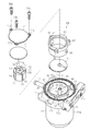
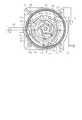
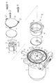
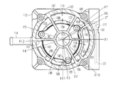
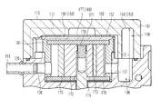
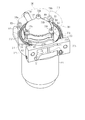
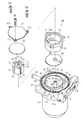
- the perspective view which shows the whole vacuum pump concerning 1st Embodiment of this invention The disassembled perspective view which shows schematic structure of the vacuum pump of FIG. Sectional drawing which shows the internal structure of the vacuum pump of FIG. The top view which abbreviate
- the perspective view of the state which removed the outer cover of the vacuum pump of FIG. The disassembled perspective view of components except the outer cover of the vacuum pump of FIG.
- the top view of the state which removed the outer cover of the vacuum pump of FIG. The perspective view which looked at the outer cover of the vacuum pump of FIG. 5 from the opening end side.
- FIG. 6 is a perspective view of a state in which a part of the outer cover of the vacuum pump in FIG. 5 is cut away.
- FIG. 13 is a sectional view taken along line 13-13 in FIG.
- the disassembled perspective view which shows schematic structure of the vacuum pump of FIG. Sectional drawing which shows the internal structure of the vacuum pump of FIG.
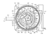
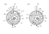
- FIG. 14 (A) And (b) is a top view which shows the positional relationship of the cylinder of the vacuum pump of FIG. 14, and the vane provided in a rotor.
- (A) And (b) is a top view which shows the positional relationship of the vane provided in the cylinder and rotor of the conventional vacuum pump.
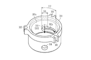
- the perspective view which shows the structure of the cylinder of the vacuum pump concerning 4th Embodiment of this invention.
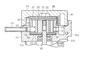
- FIG. 25 is a cross-sectional view showing the internal structure of the vacuum pump in FIG. 24.
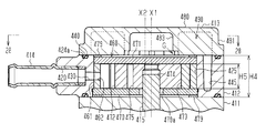
- FIG. 26 is a cross-sectional view taken along line 28-28 in FIG.
- the vacuum pump includes a motor 11, a body 12 that closes the opening of the motor 11, and an outer cover 13 that is assembled to the body 12.
- This vacuum pump is a dry pump that does not allow the air taken in and the oil to come into contact with each other by not using lubricating oil in the pump chamber.
- the body 12 is a part formed from a metal such as aluminum, and is provided on the output shaft side of the motor 11. That is, the body 12 also functions as a lid that closes the case of the motor 11.
- the body 12 is provided with a body inlet that takes air into the body 12 and a body outlet 21 that discharges air from the body 12.
- a connecting pipe 14 connected to a tank or the like to be decompressed is inserted at the body inlet.
- the outer cover 13 is made of resin and includes a cylindrical tube portion 81 and a ceiling portion 80 that closes one end portion of the tube portion 81.
- the outer cover 13 is attached to the body 12 and covers the cylinder 61.
- Bolt penetrating portions 50 for penetrating the bolts 16a to 16d are provided at four locations on the outer periphery of the cylindrical portion 81.
- the bolts 16a to 16d are hexagon socket head cap screws, for example.
- the outer cover 13 is assembled to the body 12 with its open end in contact with the upper surface 24 that is one surface of the body 12.
- the bolts 16 a to 16 d are penetrated through the bolt penetrating portion 50 and screwed into the screw holes 12 a to 12 d formed in the body 12, whereby the outer cover 13 is fixed to the body 12.
- the body 12 includes a cylindrical outer wall portion 12f and a bottom portion 12e.
- the outer wall portion 12f is provided with an attachment portion 12g for attaching the vacuum pump to an external device or the like.
- the outer wall portion 12f corresponds to the cylindrical portion of the body 12.
- the inside of the storage wall 25 corresponds to the pump chamber 27.
- the distal end surface of the housing wall 25 is formed on the same plane as the distal end surface of the upper surface 24.
- the height of the pump unit 60 is higher than the height of the pump chamber 27. For this reason, a part of the pump unit 60 is accommodated in the pump chamber 27 so as to protrude from the tip of the accommodation wall 25.
- FIG. 2 shows a state in which components other than the outer cover 13 are arranged in the extending direction of the output shaft 15 of the motor 11.
- a through hole 28 through which the output shaft 15 of the motor 11 passes is formed in the center of the bottom 12e of the body 12.
- the through hole 28 is formed at a position shifted from the center of the bottom portion 26 of the pump chamber 27.
- the housing wall 25 is formed with a pump chamber inlet 30 for taking air into the pump chamber 27 and a pump chamber outlet 31 for discharging air from the pump chamber 27.
- the pump chamber inlet 30 communicates with the body inlet 20.
- the pump chamber outlet 31 communicates with an exhaust groove 40 provided outside the housing wall 25.
- the exhaust groove 40 is formed in an annular shape along the outer peripheral surface of the housing wall 25.
- the exhaust groove 40 is provided with a first partition wall 41, a second partition wall 42, and a third partition wall 43 that partition the exhaust groove 40.
- the exhaust groove 40 is partitioned into a first exhaust groove 45, a second exhaust groove 46, and a third exhaust groove 47 in order from the pump chamber inlet 30 side by the first partition wall 41 to the third partition wall 43.
- the heights of the first partition wall 41 to the third partition wall 43 are lower than the height of the accommodation wall 25.
- the air discharged from the pump chamber outlet 31 passes through the space formed by the body 12 and the outer cover 13 and is discharged from the body outlet 21 to the outside.
- Three bolt mounting portions 33 for mounting the bolts 34a, 34b, 34c are formed on the opening end side of the housing wall 25.
- the bolt mounting portion 33 is formed at the same position as the first partition wall 41 to the third partition wall 43 in the circumferential direction of the housing wall 25.
- a stepped portion 48 is provided on the outer peripheral surface of the housing wall 25. The bolt mounting portion 33 is provided in a state continuous with the stepped portion 48.
- the pump unit 60 accommodated in the pump chamber 27 includes a rotor 72 that is a rotating body and a cylinder 61 that accommodates the rotor.
- the cylinder 61 is made of metal such as iron and is formed in a cylindrical shape.
- An inlet side communication hole 62 and an outlet side communication hole 64 are formed in the cylinder 61 at positions corresponding to the pump chamber inlet 30 and the pump chamber outlet 31 of the pump chamber 27.
- the pump chamber inlet 30 and the inlet side communication hole 62 are located on a concentric axis.
- the pump chamber outlet 31 and the outlet side communication hole 64 are located on a concentric axis.
- Three bolt insertion grooves 65 serving as a rotation restricting portion for restricting the rotation of the cylinder 61 are provided on the outer peripheral upper end portion of the cylinder 61.
- the cylinder 61 is press-fitted into the body 12 and attached to the body 12 by being screwed to the body 12. That is, the cylinder 61 is press-fitted inside the housing wall 25 of the body 12. In addition, a part of the cylinder 61 protrudes from the housing wall 25 of the body 12 in the axial direction of the rotor 72. Since the height H2 of the storage wall 25 is lower than the height H1 of the cylinder 61, the height difference (H1-H2) protrudes. One end opening of the cylinder 61 facing the outer cover 13 is closed by a pump cover 77. The other end opening of the cylinder 61 on the body 12 side is closed by the bottom portion 26 of the body 12.
- the opening of the casing 11a of the motor 11 is attached to the bottom 12e of the body 12. That is, the body 12 closes the opening of the housing 11 a of the motor 11.
- An annular bearing holding portion 29 is formed around the through hole 28 of the body 12.
- the bearing holding portion 29 is provided with a bearing 18 as a bearing portion that supports the output shaft 15 of the motor 11.
- the body 12 also functions as a lid for closing the opening of the casing 11a of the motor 11, and a separate lid for closing the opening of the casing 11a of the motor 11 is not required. Therefore, the body 12 and the lid are separated. It becomes possible to reduce weight rather than.
- the rotor 72 which accommodated the vane 73 so that it can protrude and retract is accommodated rotatably.
- the rotor 72 is made of metal such as iron, and has a shaft hole 74 and five vane receiving grooves 75 formed therein.
- a press-fit pin 76 that is press-fitted into the tip of the output shaft 15 of the motor 11 and presses the tip of the output shaft 15 against the inner peripheral surface of the shaft hole 74 is inserted into the shaft hole 74. With the output shaft 15 inserted into the shaft hole 74 of the rotor 72, the press-fit pin 76 is press-fitted into the tip of the output shaft 15 (see FIG. 3).
- Carbon vanes 73 are accommodated in the vane accommodating grooves 75, respectively.
- the opening of the cylinder 61 facing the body 12 is closed by the body side plate 70.
- the body side plate 70 is installed between the bottom portion 26 of the body 12 and the rotor 72, and the rotor 72 is slidable.
- the body side plate 70 corresponds to the first plate.
- the opening on the outer cover 13 side of the cylinder 61 is closed by the cover side plate 71.
- the cover side plate 71 is installed between the rotor 72 and the pump cover 77, and the rotor 72 is slidable.
- the cover side plate 71 corresponds to the second plate.
- the body side plate 70 and the cover side plate 71 are made of a material such as carbon having a small friction coefficient with respect to the vane 73, and are formed in a disc shape.
- the body side plate 70 includes a hole 70 a through which the output shaft 15 of the motor 11 is inserted.
- the cylinder 61 is press-fitted into the housing wall 25 of the body 12 after the body side plate 70 is installed at the bottom 26 of the pump chamber 27.
- the body side plate 70 is positioned with respect to the bottom 26 of the pump chamber 27 because the hole 70 a is eccentric.
- the pump unit 60 includes a pump cover 77 formed in a disk shape.
- the pump cover 77 is made of metal, and is formed with bolt insertion holes 77a for inserting the bolts 34a, 34b, and 34c.
- a substantially crescent-shaped space 78 is formed in the pump chamber 27 by a rotor 72 attached eccentrically in the pump chamber 27.
- a substantially crescent-shaped space 78 in the pump chamber 27 is partitioned into five compression chambers surrounded by the five vanes 73, the outer peripheral surface of the rotor 72, and the inner peripheral surface 61 a of the cylinder 61.
- compression chambers move in the same direction as the rotor 72 rotates.
- the volume of the compression chamber increases near the pump chamber inlet 30 and decreases at the pump chamber outlet 31. That is, the air sucked into the compression chamber from the pump chamber inlet 30 is compressed with the rotation of the rotor 72 and discharged from the pump chamber outlet 31.
- the rotor 72 and the vane 73 rotate in the cylinder 61 to compress the air, so that the compressed air is intermittently discharged from the pump chamber outlet 31.
- the air discharged into the first exhaust groove 45 of the exhaust groove 40 flows from the first exhaust groove 45 into the second exhaust groove 46 as indicated by an arrow F4.
- the first exhaust groove 45 and the third exhaust groove 47 are not in direct communication with each other by a partition wall (not shown) formed by the first partition wall 41 and the outer cover 13. Further, the air that has flowed into the second exhaust groove 46 flows from the second exhaust groove 46 into the third exhaust groove 47 as indicated by an arrow F5.
- the air flowing into the third exhaust groove 47 flows into the communication passage 17 from the exhaust outlet 49 and is discharged from the body outlet 21 as indicated by an arrow F6.
- the cylinder 61 is securely attached to the body 12 by being screwed into the body 12 and then screwed by the bolts 34a, 34b, 34c.
- the cylinder 61 is not entirely pressed into the body 12, but a part of the cylinder 61 protrudes from the body 12 in the axial direction of the rotor 72. For this reason, it is not necessary for the body 12 to cover the cylinder 61, and the capacity of the body 12 corresponding to the cylinder 61 protruding from the body 12 can be reduced. Therefore, the weight can be reduced by reducing the capacity of the body 12.
- the body 12 also functions as a lid for closing the opening of the casing 11a of the motor 11, and a lid for closing the opening of the casing 11a of the motor 11 is not required. For this reason, the weight can be reduced as compared with the case where the body 12 and the lid of the opening of the casing 11a of the motor 11 are separated.
- a bolt insertion groove 65 is provided on the outer periphery of the cylinder 61. For this reason, even if the rotational force of the circumferential direction generate
- the body side plate 70 and the cover side plate 71 are installed on both sides of the rotor 72 in the axial direction. For this reason, the rotor 72 can slide smoothly by the body side plate 70 and the cover side plate 71, and it becomes possible to suppress wear.
- 1st Embodiment can also be implemented with the following forms which changed this suitably.
- the resin outer cover 13 is employed, but a metal outer cover 13 other than resin may be employed, for example.
- an absorbing material or the like that absorbs vibration is provided between the ceiling portion 80 of the outer cover 13 and the pump portion 60.
- the exhaust groove 40 is provided, but the pump chamber outlet 31 may directly communicate with the body outlet 21. In such a case, the outer cover 13 may be omitted.
- the body side plate 70 and the cover side plate 71 are provided. However, if the rotor 72 can slide and rotate, the body side plate 70 and the cover side plate 71 may be omitted. Good.
- the accommodation wall 25 is provided further inside the outer wall portion 12f.
- the outer wall portion 12f and the accommodation wall 25 may be integrated.
- the exhaust groove 40 is omitted.
- the body 12 and the cylinder 61 were provided separately, you may provide integrally.
- the housing wall 25 of the body 12 and the cylinder 61 may be provided integrally.
- the cross-sectional shape of the cylinder part 81 may be any shape, such as a circle, a triangle, a quadrangle, and a star.
- the bolt insertion groove 65 is provided in the cylinder 61. However, if the cylinder 61 does not rotate, the bolt insertion groove 65 may be omitted.
- the cylinder 61 is fixed to the body 12 by press-fitting and screwing with bolts 34a, 34b, 34c, but the cylinder 61 may be fixed to the body only by press-fitting.
- the body 12 closes the opening of the housing 11a of the motor 11.
- the body 12 may include a lid that is separate from the body 12 and closes the opening of the housing 11a of the motor 11. In this case, it is preferable to provide a bearing on the lid that closes the opening of the casing 11a of the motor 11.
- the vacuum pump of the first embodiment is a dry pump and can be used as a vacuum source for various devices.
- it can also be used for a vacuum source used for a booster of a vehicle brake system, a vacuum source for a packaging machine, a printing machine, a bookbinding machine, a labeling vacuum source, a robot vacuum source, or the like.
- FIGS. 5, 7 and 8 The overall structure of the vacuum pump of the second embodiment shown in FIGS. 5, 7 and 8 is the same as the overall structure of the vacuum pump of the first embodiment shown in FIGS. Detailed descriptions of similar configurations and operations are omitted.
- the motor 111 the body 112, the screw holes 112a to 112d, the bottom portion 112e, the outer wall portion 112f, the mounting portion 112g, the outer cover 113, the connecting pipe 114, the output shaft 115, the bolts 116a to 116d, and the second embodiment.
- the rate 171, the rotor 172, the vane 173, the shaft hole 174, the vane receiving groove 175, the press-fit pin 176, the pump cover 177, the bolt insertion hole 177 a, the space 178, the ceiling part 180, and the cylinder part 181 are respectively the first embodiment.
- Motor 11 body 12, screw holes 12a to 12d, bottom portion 12e, outer wall portion 12f, mounting portion 12g, outer cover 13, connecting pipe 14, output shaft 15, bolts 16a to 16d, body inlet 20, body outlet 21, upper surface 24, housing wall 25, bottom 26, pump chamber 27, through hole 28, pump chamber inlet 30, pump chamber outlet 31, bolt mounting portion 33, bolts 34a to 34c, exhaust groove 40, first partition wall 41 to third partition Wall 43, first exhaust groove 45 to third exhaust groove 47, stepped portion 48, exhaust outlet 49, bolt through portion 50, pump portion 60, cylinder 61, inner peripheral surface 6 a, inlet side communication hole 62, outlet side communication hole 64, body side plate 70, hole 70a, cover side plate 71, rotor 72, vane 73, shaft hole 74, vane housing groove 75, press-fit pin 76, pump cover 77, It corresponds to the bolt insertion hole 77a, the space 78, the ceiling portion 80, and the cylinder portion 81.
- the outer cover 113 includes a ceiling portion 180 that constitutes a bottom portion of the outer cover 113, and a cylindrical tube portion 181 provided along the edge of the ceiling portion 180.
- Radial ribs 188 are formed on the surface of the ceiling portion 180 of the outer cover 113 that faces the body 112 when assembled to the body 112.
- the radial rib 188 includes an annular rib 189 provided at the center of the ceiling portion 180, and six linear ribs 192 extending linearly from the annular rib 189 toward the cylindrical portion 181.
- the radial ribs 188 suppress the vibration of the ceiling part 180 by reinforcing the ceiling part 180. Thereby, the noise accompanying the vibration of the ceiling part 180 is suppressed.
- a first protrusion 186 and a second protrusion 187 are formed on the cylindrical portion 181 of the outer cover 113.
- the first protrusion 186 and the second protrusion 187 protrude from the cylindrical part 181 toward the inner side in the radial direction of the outer cover 113 and are continuous with the ceiling part 180.
- a curved wall portion 183 that defines an arcuate space 182 that is an arcuate space is formed inside the outer cover 113.
- the curved wall portion 183 protrudes from the ceiling portion 180 and is formed in a state where both ends thereof are connected to the cylindrical portion 181.
- the curved wall portion 183 is formed such that the width W1 in the short direction of the arcuate space 182 inside thereof increases from one end 185 to the other end 184 in the longitudinal direction of the arcuate space 182.
- the arcuate space 182 defined by the curved wall portion 183 faces the first exhaust groove 145 when the outer cover 113 is assembled to the body 112.
- the arc-shaped space 182 and the first exhaust groove 145 constitute a small expansion chamber 191 that expands the air discharged from the pump chamber 127.
- the end portion 184 having a relatively large width W ⁇ b> 1 of the arc space 182 is when the outer cover 113 is assembled to the body 112.
- a partition wall 190 that separates the pump chamber outlet 131 and the exhaust outlet 149 is formed by the end 184 and the first partition wall 141.
- the curved wall portion 183, the first protrusion portion 186 and the second protrusion portion 187 of the outer cover 113, and the first exhaust groove 145 to the third exhaust groove 147 of the body 112 are relative in the circumferential direction.
- the curved wall portion 183, the first protrusion portion 186 and the second protrusion portion 187 of the outer cover 113, and the first exhaust groove 145 to the third exhaust groove 147 of the body 112 are relative in the circumferential direction.
- the curved wall portion 183, the first protrusion portion 186 and the second protrusion portion 187 of the outer cover 113, and the first exhaust groove 145 to the third exhaust groove 147 of the body 112 are relative in the circumferential direction.
- the output shaft 115 of the motor 111 is eccentric with respect to the center of the pump chamber 127, but coincides with the radial center of the outer cover 113.
- the exhaust outlet 149 formed at the end of the third exhaust groove 147 and the pump chamber outlet 131 formed at the start of the first exhaust groove 145 are a first partition wall 141 of the body 112 and a curved wall portion 183 of the outer cover 113. Are separated by a partition wall 190 constituted by the end portions 184 of the rim.
- the pump chamber outlet 131 is angled clockwise (direction) from the position of the partition wall 190. It is provided at the position of ⁇ 1.
- the starting end of the first exhaust groove 145 is located at an angle “0 °”, and the end of the first exhaust groove 145 is located at an angle ⁇ 2.
- the second exhaust groove 146 is provided from the angle ⁇ 3 to the angle ⁇ 4.
- the third exhaust groove 147 is provided from the angle ⁇ 5 to the angle ⁇ 6.
- the exhaust outlet 149 is provided at a position of an angle ⁇ 7 smaller than the angle ⁇ 6.
- the first exhaust groove 145 to the third exhaust groove 147 become the first expansion chamber 196 to the third expansion chamber 198 by being covered with the outer cover 113.
- the first expansion chamber 196 to the third expansion chamber 198 constitute an exhaust passage 210.
- the exhaust passage 210 including the first expansion chamber 196 to the third expansion chamber 198 is provided over 360 ° including the thickness of the first partition wall 141 to the third partition wall 143.
- the angle from the angle ⁇ 1 that is the position of the pump chamber outlet 131 to the angle ⁇ 7 that is the position of the exhaust outlet 149 is the angle “ ⁇ 7 ⁇ 1”.
- the angle “ ⁇ 7 ⁇ 1” is preferably larger than 180 °.
- the angle “ ⁇ 7 ⁇ 1” is desirably as large as possible, and is preferably 270 ° or more.
- the curved wall portion 183 is indirectly in contact with the body 112 at a portion including one end portion 184 thereof.
- the wall portion closer to the accommodation wall 125 is provided on the outer side in the radial direction of the accommodation wall 125 and does not contact the accommodation wall 125.
- the curved wall portion 183 extends from the angle “0 °” to the angle ⁇ 10 along the first exhaust groove 145.
- a small expansion chamber 191 is defined by the curved wall portion 183 and the first exhaust groove 145.
- the angle ⁇ 10 that is the terminal position of the curved wall portion 183 is smaller than the angle ⁇ 2 that is the terminal position of the first exhaust groove 145.
- the first exhaust groove 145 is provided with an opening 195 that is not covered by the curved wall 183.
- the first expansion chamber 196 is defined by the first exhaust groove 145, the outer cover 113, and the pump unit 160.
- the first expansion chamber 196 includes a small expansion chamber 191 formed by the arcuate space 182 and the first exhaust groove 145.
- the second expansion chamber 197 is defined by the second exhaust groove 146, the outer cover 113, and the pump unit 160.
- the first protrusion 186 is provided between the first expansion chamber 196 and the second expansion chamber 197.
- a gap is provided between the distal end of the first protrusion 186 in the radial direction and the pump unit 160.
- the angle ⁇ 11 that is the position of the first protrusion 186 is larger than the angle ⁇ 3 that is the position of the start end of the second exhaust groove 146. That is, the first protrusion 186 is provided at a position shifted from the starting end of the second exhaust groove 146, and a first inflow port 199 is formed between them.
- a third expansion chamber 198 is defined by the third exhaust groove 147, the outer cover 113, and the pump unit 160.
- the second protrusion 187 is provided between the second expansion chamber 197 and the third expansion chamber 198.
- a gap is provided between the distal end of the second protrusion 187 in the radial direction and the pump unit 160.
- the angle ⁇ 12 which is the position where the second protrusion 187 is provided, is larger than the angle ⁇ 4, which is the terminal end of the second exhaust groove 146, and smaller than the angle ⁇ 5, which is the start end of the third exhaust groove 147. Accordingly, the second inflow port 200 is formed between the second protrusion 187, the body 112, and the pump unit 160.
- the air discharged into the small expansion chamber 191 is directed to the exhaust outlet 149 that directly communicates with the body outlet 121 by the partition wall 190 formed by the first partition wall 141 of the body 112 and the curved wall portion 183 of the outer cover 113. Flow is hindered. That is, the first expansion chamber 196 and the third expansion chamber 198 are not in direct communication by the partition wall 190. Therefore, after the air discharged into the small expansion chamber 191 is expanded in the small expansion chamber 191, it passes between the opening 195, the outer cover 113, and the pump section 160 as indicated by an arrow D2. , Flows from the first inlet 199 into the second expansion chamber 197.
- the second partition wall 142 serves as a throttle that allows air to pass while generating a pressure difference between the upstream side and the downstream side. Functions and contracts air flow. Further, the first inlet 199 provided between the first expansion chamber 196 and the second expansion chamber 197 also functions as a throttle, and contracts the air flow.
- the third partition wall 143 functions as a throttle that reduces the cross-sectional area of the flow path while allowing air to pass therethrough. Shrink.
- the second inlet 200 also functions as a throttle that reduces the cross-sectional area of the flow path, and contracts the air flow.
- the air that has flowed into the third expansion chamber 198 expands again, and then flows into the communication path 117 from the exhaust outlet 149 as indicated by an arrow D4. Since the flow passage cross-sectional area of the communication path 117 is smaller than that of the third expansion chamber 198, the flow of air flowing into the communication path 117 is contracted and discharged from the body outlet 121 as indicated by an arrow D5.
- an urging unit 202 such as a wave washer is provided between the pump unit 160 and the outer cover 113, and presses the pump unit 160 toward the body 112. Further, since the ceiling portion 180 of the outer cover 113 and the pump portion 160 are separated from each other, a gap 201 is provided between the ceiling portion 180 of the outer cover 113 and the pump portion 160. For this reason, since the vibration of the rotor 172 is transmitted to the outer cover 113 side through the gap 201, the vibration energy of air is attenuated and the vibration of the outer cover 113 is suppressed. A part of the air discharged from the small expansion chamber 191 passes through the gap 201, crosses the pump unit 160, and goes to the exhaust outlet 149. However, since the height of the gap 201 is smaller than the volume of the first expansion chamber 196 to the third expansion chamber 198, most of the air discharged from the small expansion chamber 191 goes to the second expansion chamber 197.
- the vacuum pump provided with the exhaust passage 210, most of the air exhausted from the pump chamber outlet 131 is exhausted from the body outlet 121 after passing through the annular exhaust passage 210 outside the pump chamber 127.
- the path length from the pump chamber outlet 131 to the body outlet 121 is longer than the shortest path from the pump chamber outlet 131 to the exhaust outlet 149. Since the vibration energy of air is attenuated as the distance through which air flows increases, noise can be reduced by increasing the flow path length from the pump chamber outlet 131 to the body outlet 121.
- the air repeats expansion and contraction a plurality of times. As a result, air pulsation is attenuated, and noise caused by vibration is suppressed. Further, when the air passes through the exhaust passage 210, the air swirls around the outer periphery of the pump unit 160, so that the air can be rectified. For this reason, the pulsation of air generated when air is discharged from the pump chamber outlet 131, the collision of air in the exhaust passage 210, and the like can be suppressed, and the generation of noise can be suppressed. Further, since the outer cover 113 is made of a resin having a sound absorbing property compared to metal or the like, vibration of air discharged from the exhaust outlet 149 can be suppressed.
- the following effects can be obtained. (7)
- a passage longer than the shortest length along the exhaust passage 210 from the pump chamber outlet 131 to the exhaust outlet 149 is formed.
- the length of the exhaust passage 210 can be increased. For this reason, since the effect of attenuating the vibration energy of air in the exhaust passage 210 can be enhanced, noise associated with exhaust from the body outlet 121 can be reduced.
- the air is rectified by passing along the outer circumferential direction of the pump chamber 127, thereby pulsating air generated when the air is discharged from the pump chamber outlet 131, and air in the exhaust passage 210. The collision between each other can be suppressed, and the generation of noise can be suppressed.
- the air passing through the exhaust passage 210 is expanded at portions other than the first partition wall 141 to the third partition wall 143 and contracts when passing through the first partition wall 141 to the third partition wall 143. As described above, the air expands and contracts in the exhaust passage 210, whereby the pulsation of the air generated when the air is discharged from the pump chamber outlet 131 is attenuated, so that the noise reduction effect can be enhanced.
- the air passing through the exhaust passage 210 is It is expanded at a portion other than the projection 186 and the second projection 187 and contracts when passing through the first projection 186 and the second projection 187. Since air expands and contracts in the exhaust passage in this way, air pulsation that occurs when air is discharged from the pump chamber outlet 131 is attenuated, so that the noise reduction effect can be enhanced.
- the gap 201 is provided between the ceiling portion 180 and the pump portion 160 by separating the ceiling portion 180 and the pump portion 160 of the outer cover 113 from each other.
- the vibration energy is attenuated, so that noise due to the vibration of the ceiling portion 180 can be reduced.
- the gap 201 between the ceiling part 180 of the outer cover 113 and the pump part 160 the volume of the exhaust passage 210 formed by the outer cover 113 covering the first exhaust groove 145 to the third exhaust groove 147 is increased. can do. For this reason, the expansion effect of air can be heightened.
- the shortest length from the pump chamber outlet 131 to the exhaust outlet 149 is determined by the first partition wall 141 formed on the body 112 and the end 184 of the curved wall 183 formed on the outer cover 113.
- a partition wall 190 that suppresses the flow of air through the path was formed.
- the partition may be formed only by the first partition wall 141 formed on the body 112.
- the first partition wall 141 is formed higher than the height of the first exhaust groove 145 and protrudes toward the outer cover 113.
- the partition wall may be formed by the end portion 184 of the curved wall portion 183 formed in the outer cover 113.
- the end 184 of the curved wall portion 183 protrudes from the opening end of the outer cover 113, and the end 184 is inserted toward the exhaust groove 140 when the outer cover 113 is assembled to the body 112. It is.
- the exhaust groove 140 is divided into three by the first partition wall 141 to the third partition wall 143.
- the exhaust groove 140 may be divided into two, or may be divided into four or more.
- the number of protrusions of the outer cover 113 that functions as a throttle for reducing the cross-sectional area of the flow path may be one, or may be three or more.
- the height and the length along the radial direction of the outer cover 113 can be changed.
- the protrusion may have a height that is inserted into the body 112 side.
- the number of partition walls of the body 112 that functions as an aperture for reducing the cross-sectional area of the flow path may be one, or a plurality of three or more.
- the height and the length along the radial direction of the body 112 can be changed.
- the partition wall may have a height inserted into the outer cover 113 side.
- the ceiling part 180 of the outer cover 113 and the pump part 160 may be in contact with each other.
- an absorbing material or the like that absorbs vibration is provided between the ceiling portion 180 of the outer cover 113 and the pump portion 160.
- radial rib 188 was formed in the ceiling part 180 of the outer cover 113, you may form a rib of shapes other than this.
- a plurality of protrusions that intersect at the radial center may be formed.
- a plurality of protrusions extending in parallel may be formed.
- the resin outer cover 113 is used, but a metal outer cover 113 other than resin, for example, may be used.
- a metal outer cover 113 it is preferable that an absorbing material or the like that absorbs vibration is provided between the ceiling portion 180 of the outer cover 113 and the pump portion 160.
- the vacuum pump is provided with the motor 111 as a drive source, but it is not necessarily provided with a drive source, and may be connected to an external drive source.
- a rotating shaft inserted through the rotor 172 may be connected to the crankshaft of the engine.
- you may connect with the rotating shaft of another drive device.
- the pump part 160 was accommodated in the pump chamber 127 in the state which one part protruded from the pump chamber 127, the height of the pump part 160 shall be below the height of the pump 127 chamber, and a pump part 160 may be accommodated without protruding from the pump chamber 127.
- the cylinder 161 and the body 112 are separated from each other, and the pump 161 including the cylinder 161 is fixed to the body 112 by press-fitting the cylinder 161 and screwing the bolts 134a to 134c.
- the cylinder 161 may be cast into the body 112. Further, the cylinder 161 and the body 112 may be the same member, and the cylinder 161 may be omitted.
- the vacuum pump is embodied as a vane pump, but a pump other than the vane pump may be used.
- a gear pump including a pair of gears that mesh with each other as a rotating body may be used.
- the vacuum pump according to the second embodiment is a dry pump and can be used as a vacuum source for various devices because noise is reduced.
- it can also be used for a vacuum source used for a booster of a vehicle brake system, a vacuum source for a packaging machine, a printing machine, a bookbinding machine, a labeling vacuum source, a robot vacuum source, or the like.
- FIGS. 14, 15 and 17 The overall structure of the vacuum pump of the third embodiment shown in FIGS. 14, 15 and 17 is the same as the overall structure of the vacuum pump of the first embodiment shown in FIGS. Detailed descriptions of similar configurations and operations are omitted.
- the rotor 372 is rotated counterclockwise as viewed from above.
- the cylinder 361 corresponds to a cylinder portion and is separate from the body 312.
- the inlet side communication hole 362a corresponds to the cylinder part inlet, and the outlet side communication hole 364 corresponds to the cylinder part outlet.
- the inlet side communication hole 362a communicates with all of the pump chamber inlet 330 (body inlet 320), and is in a direction opposite to the rotation direction of the rotor 372 with respect to the pump chamber inlet 330 (body inlet 320). It is an elongated hole. That is, the inlet side communication hole 362a is a long hole extending clockwise with respect to the pump chamber inlet 330 (body inlet 320). The opening of the inlet side communication hole 362a includes all the openings of the pump chamber inlet 330 (body inlet 320). In other words, the diameter D6 of the opening of the pump chamber inlet 330 (body inlet 320) is smaller than the length D7 in the longitudinal direction of the opening of the inlet communication hole 362a.
- the inlet side communication hole 362 a is provided in a range within the interval B between adjacent vanes 373 among the plurality of vanes 373. That is, the length D7 in the longitudinal direction of the opening of the inlet side communication hole 362a is set to be equal to or smaller than the interval B between the adjacent vanes 373.
- the interval B between the adjacent vanes 373 is such that the adjacent inner vanes 373 are in the vicinity of the inlet-side communication hole 362a and the inner peripheral surfaces of the cylinders 361 between the portions where the tips of the vanes 373 are in contact with the inner peripheral surface 361a of the cylinder 361. It is the length along 361a.
- FIG. 19 shows the load applied to the vane 373 at each rotational position P1 to P10 of the vane 373
- the load load of the third embodiment is shown by a solid line
- the conventional load load is shown by a broken line.
- the rotation positions P1 to P10 are indicated by the positions of lines connecting the rotation center of the rotor 372 and the portion where the tip of the vane 373 contacts the inner peripheral surface 361a of the cylinder 361.
- the rotation position P1 is a position immediately after the vane 373 passes through the inlet side communication hole 362a.
- the rotational position P10 is a position where the vane 373 is included in the opening of the inlet side communication hole 362a.
- the rotational position P1 is a position immediately after the vane 373 passes through the inlet side communication hole 362a.
- the rotational position P10 is a position before the vane 373 passes through the inlet side communication hole 362b.
- FIG. 21 shows the load load at each rotational position of the vane 373 when the vacuum pump is in the atmospheric release state, the lower limit pressure state in the actual use region, and the upper limit pressure state in the actual use region.
- the load applied to the vane 373 at the rotational position P10 of the third embodiment is smaller than the load applied to the vane 373 at the conventional rotational position P10, and is substantially 0 (N). That is, in the third embodiment, since the inlet side communication hole 362a is formed as a long hole, if the circular inlet side communication hole 362b shown in FIG. As shown in FIG. 19B, air is taken into the compression chamber before this through the inlet side communication hole 362a.
- the volumes of the plurality of compression chambers partitioned by the vanes are changed while rotating in the rotation direction of the rotor.
- the inventor states that the compression chamber formed at the position including the inlet-side communication hole is in a state in which air is taken in from the inlet-side communication hole, and the compression chamber formed before the position including the inlet-side communication hole has an air It was discovered that the pressure difference before and after the vane was the largest and the load applied to the vane was large.
- the inlet-side communication hole 362a communicates with the pump chamber inlet 330 (body inlet 320), and is a long hole extending in the direction opposite to the rotation direction of the rotor 372 with respect to the pump chamber inlet 330 (body inlet 320). For this reason, since air is also taken in from the inlet side communication hole 362a in the compression chamber formed before the position including the inlet side communication hole 362a, in which air has not been taken in from the conventional inlet side communication hole 362a, the inlet side communication hole 362a The pressure difference before and after the vane 373 in the vicinity of the hole 362a is almost eliminated, and the load applied to the vane 373 can be reduced. Therefore, since the amount of wear of the vane 373 can be reduced, the life of the vane 373 can be extended.
- the inlet side communication hole 362a is provided in a range within the interval B between the adjacent vanes 373. For this reason, only the pressure difference between the adjacent compression chambers located before and after the inlet side communication hole 362a can be suppressed, and there is no change in the pressure other than the adjacent compression chambers located before and after the inlet side communication hole 362a. Thus, while maintaining the conventional compression efficiency, the load applied to the vane 373 can be suppressed, and the life of the vane 373 can be extended.
- the vacuum pump of the fourth embodiment is different from the third embodiment in that the inlet side communication hole 362a is a circular hole instead of a long hole, and a recess is provided instead of the long hole.
- the difference from the third embodiment will be mainly described.
- the cylinder 361 has an inlet side communication hole 362 b formed at a position corresponding to the pump chamber inlet 330 of the pump chamber 327. That is, the inlet side communication hole 362 b communicates with the body inlet 320. The inlet side communication hole 362b corresponds to the cylinder portion inlet.
- the inner peripheral surface 361 a of the cylinder 361 includes a portion where the inlet-side communication hole 362 b is located in the axial direction of the rotor 372, and a recess 366 extending in the direction opposite to the rotational direction of the rotor 372 along the circumferential direction of the cylinder 361. Is provided. That is, in the circumferential direction of the cylinder 361, the recess 366 is positioned so as to include the range of the diameter D8 of the inlet side communication hole 362b.
- the length W2 of the recess 366 in the circumferential direction of the cylinder 361 is set to be longer than the diameter D8 of the inlet side communication hole 362b.
- the recessed part 366 is provided in the range within the space
- the recessed part 366 is formed in the internal peripheral surface 361a of the cylinder 361, if the circular inlet side communication hole 362b shown in FIG. Air is taken into the compression chamber on the front side through the recess 366. For this reason, as in the third embodiment, there is almost no pressure difference before and after the vane 373 at the rotational position P10 of the vane 373, and the load applied to the vane 373 can be reduced. Therefore, the life of the vane 373 can be extended.
- a compression chamber is formed by adjacent vanes, rotors, and cylinders.
- the inventor states that the compression chamber formed at the position including the inlet-side communication hole is in a state in which air is taken in from the inlet-side communication hole, and air is supplied to the compression chamber formed before the position including the inlet-side communication hole. Since it was discharged, the pressure difference in the compression chamber was the largest, and it was found that the load applied to the vane was large.
- the inner peripheral surface of the cylinder 61 is provided with the recess 66 extending in the direction opposite to the rotation direction of the rotor 72 along the circumferential direction of the cylinder 61. For this reason, air is also taken in through the recess into the compression chamber formed before the position including the inlet side communication hole where air has not been taken in from the conventional inlet side communication hole. There is almost no pressure difference between the front and back, and the load applied to the vane can be reduced. Therefore, since the amount of wear of the vane can be reduced, the life of the vane can be extended.
- a recess 366 is provided in a range within an interval between adjacent vanes 373. For this reason, only the pressure difference between the adjacent compression chambers located before and after the inlet side communication hole 362b can be suppressed, and there is no change in the pressure other than the adjacent compression chambers located before and after the inlet side communication hole 362b. Thus, while maintaining the conventional compression efficiency, the load applied to the vane 373 can be suppressed, and the life of the vane 373 can be extended.
- the inlet side communication hole 362a communicates with the pump chamber inlet 330 (body inlet 320) entirely, but may communicate with only a part of the pump chamber inlet 330 (body inlet 320).
- the inlet side communication hole 362a is a long hole extending only in the direction opposite to the rotation direction of the rotor 372.
- the inlet side communication hole 362a may be a long hole extending in the rotation direction of the rotor 372. Good.
- the recess 366 extends only in the direction opposite to the rotation direction of the rotor 372, but the recess 366 may also extend in the rotation direction of the rotor 372.
- the recessed part 366 was provided in the internal peripheral surface 361a of the cylinder 361, it replaces with the recessed part 366, and while connecting with the recessed part connected with the inlet side communication hole 362b on the outer peripheral surface of the cylinder 361, and a recessed part.
- a through hole penetrating the cylinder 361 may be provided. For example, as shown in FIG.
- a recess 367 including a portion where the inlet-side communication hole 362b is located in the axial direction of the rotor 372 and extending at least in the direction opposite to the rotation direction of the rotor 372 along the circumferential direction of the cylinder 361;
- a through hole 368 is provided on the rear side of the inlet side communication hole 362 b in the rotation direction of the rotor 372, communicates with the recess 367, and penetrates the cylinder 361. That is, in the circumferential direction of the cylinder 361, the recess 367 is positioned so as to include the range of the diameter D9 of the inlet side communication hole 362b.
- the length W3 of the recess 367 in the circumferential direction of the cylinder 361 is set to be longer than the diameter D9 of the inlet side communication hole 362b.
- the recessed part 367 is provided in the range within the space
- the through hole 368 is positioned such that the diameter D10 of the through hole 368 is included in the length W3 of the recess 367.
- the outer cover 313 made of resin is adopted, but an outer cover 313 made of metal other than resin, for example, may be adopted.
- an absorbing material or the like that absorbs vibration is provided between the ceiling portion 380 and the pump portion 360 of the outer cover 313.
- the exhaust groove 340 is provided, but the pump chamber outlet 331 may communicate directly with the body outlet 321. In such a case, the outer cover 313 may be omitted.
- the body side plate 370 and the cover side plate 371 are provided, but if the rotor 372 can slide and rotate, the body side plate 370 and the cover side plate 371 are omitted. May be.
- the accommodation wall 325 is provided further inside the outer wall portion 312f, but the outer wall portion 312f and the accommodation wall 325 may be integrated. In this case, the exhaust groove 340 is omitted.
- the bolt insertion groove 365 is provided in the cylinder 361.
- the bolt insertion groove 365 may be omitted if it can be fixed by press-fitting and screwing with the bolts 334a, 334b, and 334c. .
- the cylinder 361 is press-fitted into the body 312 and screwed.
- the method of assembling the cylinder 361 and the body 312 is not limited to this.
- the cylinder may be used when casting the body. It may be cast together.
- the cylinder 361 and the body 312 are separated from each other, but the cylinder 361 and the body 312 may be integrally formed if desired performance can be obtained with the same material.
- the vacuum pump of 3rd and 4th embodiment is a dry pump, and can be used as a vacuum source of various apparatuses.
- it can also be used for a vacuum source used for a booster of a vehicle brake system, a vacuum source for a packaging machine, a printing machine, a bookbinding machine, a labeling vacuum source, a robot vacuum source, or the like.
- the vacuum pump includes a motor 411, a body 412 assembled on the output shaft side of the motor 411, and a pump cover 413 that closes the opening of the body 412.
- This vacuum pump is a dry pump that does not use the lubricating oil in the pump chamber so that the air taken in does not come into contact with the oil.
- the body 412 is a cylindrical part formed of a metal such as aluminum.
- the body 412 is provided with a body inlet 420 that takes air into the body 412 and a body outlet 421 that discharges air from the body 412.
- the body inlet 420 and the body outlet 421 are provided on the side surface of the body 412, that is, the surface along the axial direction of the rotation shaft of the motor 411.
- a connecting pipe 414 connected to a tank or the like to be decompressed is inserted into the body inlet 420.
- the pump cover 413 is formed of a metal such as aluminum, and includes a cylindrical tube portion 481 and a closing lid portion 480 that closes one end portion of the tube portion 481.
- Bolt penetrating portions 450 for penetrating the bolts 416 are provided at two locations on the outer periphery of the cylindrical portion 481.
- the bolt 416 is, for example, a hexagon socket head cap screw.
- the pump cover 413 is assembled to the body 412 in a state where the open end of the pump cover 413 is in contact with the upper surface 424 on the cover side which is one surface of the body 412.
- An annular seal groove 424 a is formed on the upper surface 424 of the body 412 so as to surround the pump chamber 427.
- An annular seal member 440 is disposed in the seal groove 424a.
- the pump cover 413 is fixed to the upper surface 424 of the body 412 by the bolt 416 penetrating through the bolt penetrating portion 450 and screwed into the screw hole 412 a formed in the body 412.
- a pair of attachment portions 412 c for attaching the vacuum pump to an external device or the like is provided on the outer wall portion 412 b of the body 412.
- the body 412 is provided with a housing wall 425 having a hole formed in the axial direction of the rotation axis X ⁇ b> 1 of the motor 411.
- the central axis X2 of the housing wall 425 is formed at a position shifted from the rotational axis X1 of the motor 411.
- the inside of the accommodation wall 425 corresponds to the pump chamber 427.
- the housing wall 425 houses a pump unit 460 that functions as a pump.
- the pump unit 460 includes a cylindrical cylinder 461 and a rotor 472 that is a columnar rotating body.
- the cylinder 461 is made of metal such as iron.
- a cylinder 461 is cast into the housing wall 425 of the body 412.
- the body 412 in which the cylinder 461 is integrally cast is cast by pouring the mold 461 with the cylinder 461 installed in the mold.
- the length H1 of the body 412 in the direction of the rotation axis X1 is longer than the length H2 of the cylinder 461 in the direction of the rotation axis X1.
- the cylinder 461 does not protrude from the body 412, and the body 412 can be downsized.
- the body 412 is formed of a material having higher thermal conductivity than the rotor 472. According to this, the heat generated in the pump unit 460 is quickly transmitted to the body 412 and can be radiated from the body 412.
- the pump cover 413 is formed of a material having high thermal conductivity, the heat generated in the pump unit 460 is quickly transmitted to the pump cover 413 and can be radiated from the pump cover 413.
- a rotor 472 is rotatably accommodated inside the cylinder 461.
- the rotor 472 is made of metal such as iron, and has a shaft hole 474 and five vane housing grooves 475 (see FIG. 26). Spline grooves (not shown) that mesh with each other are formed on the inner peripheral surface of the shaft hole 474 and the tip of the output shaft 415. Carbon vanes 473 are housed in the vane housing grooves 475 so as to be able to appear and retract.
- the opening on the body 412 side of the cylinder 461 is closed by the body side plate 470. Further, the opening on the pump cover 413 side of the cylinder 461 is closed by a cover side plate 471.
- the body side plate 470 and the cover side plate 471 are made of a material such as carbon having a small friction coefficient with respect to the vane 473, and are formed in a disc shape.
- the body side plate 470 is formed with a hole 470a through which the output shaft 415 of the motor 411 is inserted.
- the diameters of the body side plate 470 and the cover side plate 471 are set larger than the inner diameter of the cylinder 461.
- the body side plate 470 and the cover side plate 471 are respectively urged by the wave washer 479 and pressed against each opening of the cylinder 461.
- a seal ring may be provided instead of the wave washer 479.
- the accommodation wall 425 is formed with a pump chamber inlet 430 for taking air into the pump chamber 427 and a pump chamber outlet 431 for discharging air from the pump chamber 427.
- the pump chamber inlet 430 is in communication with the body inlet 420.
- the pump chamber outlet 431 communicates with a first exhaust groove 445 provided outside the accommodation wall 425.
- the first exhaust groove 445 is formed at a position far from the pump chamber inlet 430 along the outer peripheral surface of the housing wall 425.
- the body outlet 421 communicates with a second exhaust groove 446 provided outside the accommodation wall 425.
- a check valve 422 for preventing a backflow of air into the body 412 is attached to the body outlet 421.
- an inlet side communication hole 462 formed at a position corresponding to the pump chamber inlet 430 of the pump chamber 427 and an outlet side communication hole 464 formed at a position corresponding to the pump chamber outlet 431 are formed. ing. Inside the cylinder 461, a sealed pump chamber 427 is formed except for the inlet side communication hole 462 and the outlet side communication hole 464 that are connected to the connection pipe 414. The outlet side communication hole 464 corresponds to the cylinder outlet.
- an expansion chamber 490 is formed by the inside of the first exhaust groove 445, the second exhaust groove 446, and the pump cover 413.
- the compressed air flowing into the expansion chamber 490 expands and disperses in the expansion chamber 490, collides with the radial ribs 482 of the expansion chamber 490, and is irregularly reflected. Thereby, since the sound energy of compressed air is attenuated, noise and vibration during exhaust can be reduced.
- a substantially crescent-shaped space 478 is formed in the pump chamber 427 by a rotor 472 that is eccentrically mounted in the pump chamber 427.
- compression chambers move in the same direction as the rotor 472 rotates.
- the volume of the compression chamber increases near the pump chamber inlet 430 and decreases at the pump chamber outlet 431. That is, the air sucked into one compression chamber from the pump chamber inlet 430 is compressed as the rotor 472 rotates and is discharged from the pump chamber outlet 431.
- the rotor 472 and the vane 473 rotate in the cylinder 461 to compress the air, so the compressed air is intermittently discharged from the pump chamber outlet 431.
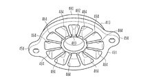
- radial ribs 482 are formed inside the pump cover 413.
- the radial ribs 482 include an annular rib 483 provided at the center of the closed lid portion 480, and a plurality of (12 in the fifth embodiment) linear ribs 484 extending linearly from the annular rib 483 toward the tube portion 481. Become. Since the radial ribs 482 reinforce the closing portion 480, vibration of the closing portion 480 is suppressed. Thereby, the noise accompanying the vibration of the lid closing part 480 is suppressed.
- the annular rib 483 has a height lower than the linear rib 484 from the lid portion 480.
- a gap G is provided between the annular rib 483 and the cover side plate 471. For this reason, air can go back and forth between the spaces defined by the straight ribs 484 through the gaps G formed by the lower annular ribs 483.
- the gap G functions as a throttle that generates a pressure difference between the upstream side and the downstream side when it passes, and contracts the air flow.
- a space communicating with the first exhaust groove 445 is defined as a first space S1
- a space communicating with the second exhaust groove 446 is defined as a second space.
- a space that is not in communication with the first exhaust groove 445 and the second exhaust groove 446 is referred to as a third space S3.
- a space defined by the annular rib 483 is referred to as a fourth space S4.
- the air that has flowed into the first exhaust groove 445 includes the fourth space S4 partitioned by the annular rib 483 from the first space S1 partitioned by the straight rib 484 and the second space S2 partitioned by the straight rib 484.
- the second exhaust groove 446 cannot be reached without passing through. Therefore, the distance that the air discharged from the pump chamber 427 to the first exhaust groove 445 flows before being discharged from the body outlet 421 can be increased.
- FIG. 26 when the rotor 472 rotates by driving the motor 411, it passes through the body inlet 420, the pump chamber inlet 430, and the inlet side communication hole 462 via the connecting pipe 414 as indicated by an arrow F13. Thus, air is taken into the pump chamber 427. The air sucked into the compression chamber partitioned by the vanes 473 and the like is compressed as shown by an arrow F14, and is discharged from the pump chamber outlet 431 to the first exhaust groove 445 and expanded as shown by an arrow F15. .
- the air discharged into the first exhaust groove 445 passes through the first space S1 defined by the straight rib 484 from the first exhaust groove 445, as indicated by an arrow F16, and the first exhaust
- the space S1 is contracted by the gap G, flows into the fourth space S4 defined by the annular rib 483, and expands.
- the air that has flowed into the fourth space S4 partitioned by the annular rib 483 swirls within the fourth space S4 partitioned by the annular rib 483 as indicated by an arrow F17, and a gap is formed as indicated by an arrow F18.
- Shrinked by G flows into the third space S3 defined by the straight ribs 484, and expands.
- the air flowing into the third space S3 is contracted by the gap G as shown by an arrow F19, flows into the fourth space S4 defined by the annular rib 483, and expands. Further, the air that has flowed into the fourth space S4 defined by the annular rib 483 is contracted by the gap G as shown by an arrow F20, and flows into the second space S2 defined by the linear rib 484 to expand. However, it flows into the second exhaust groove 446.
- the air that has flowed into the second exhaust groove 446 is discharged to the outside through the check valve 422 of the body outlet 421 as indicated by an arrow F21.
- the rotor 472 provided with the vane 473 rotates, compressed air is intermittently discharged from the pump chamber outlet 431, so the distance from the pump chamber outlet 431 to the body outlet 421 is short. Then, noise may be generated at the body outlet 421 due to pressure pulsation occurring at a constant fundamental frequency.
- the following effects can be achieved.
- the closing cover part 480 is separated from the body 412 by the amount of the cylinder part 481 so that a space is provided in the pump cover 413. become able to. Thereby, the air discharged from the outlet side communication hole 464 can be expanded in the space in the pump cover 413, and the exhaust noise can be reduced.
- the radial ribs 482 are provided inside the pump cover 413, the strength of the pump cover 413 can be improved and vibration can be suppressed, so that noise due to vibration of the closing cover 480 can be reduced.
- 5th Embodiment can also be implemented with the following forms which changed this suitably.
- the cylinder 461 is prevented from protruding from the end surface (upper surface 424) of the body 412 on the pump cover 413 side. However, if there is a margin in the space formed by the body 412 and the pump cover 413, 461 may protrude from the body 412.
- the body 412 is provided with an outlet for discharging air to the outside of the vacuum pump.
- the outlet may be provided not on the body 412 but on the pump cover.
- the annular rib 483 is made lower than the straight rib 484 so as to function as a diaphragm.
- the annular rib 483 and the straight rib 484 may have the same height.
- the number of linear ribs 484 provided on the inner side of the pump cover 413 is not limited to 12 and can be arbitrarily set.
- the radial ribs 482 are provided inside the pump cover 413.
- the annular ribs 483 may be omitted from the radial ribs 482 and only the straight ribs 484 may be used.
- the radial rib 482 having the annular rib 483 and the linear rib 484 is provided inside the pump cover 413.
- the present invention is not limited to the combination of the annular rib 483 and the linear rib 484, and the pump cover 413 Other shapes may be used such that the air flowing into the inner expansion chamber 490 is agitated.
- the cylinder 461 when the body 412 is cast, the cylinder 461 is cast together.
- the method of assembling the cylinder 461 and the body 412 is not limited to this.
- the cylinder 461 is press-fitted into the body 412. It may be screwed.
- the vacuum pump is embodied as a vane pump, but a pump other than the vane pump may be used.
- a gear pump including a pair of gears that mesh with each other as a rotating body may be used.
- the vacuum pump according to the fifth embodiment is a dry pump and has reduced noise, so that it can be used as a vacuum source for various devices.
- it can also be used for a vacuum source used for a booster of a vehicle brake system, a vacuum source for a packaging machine, a printing machine, a bookbinding machine, a labeling vacuum source, a robot vacuum source, or the like.
- the body 412 and the cylinder 461 are provided separately, but may be provided integrally.
- the housing wall 425 of the body 412 and the cylinder 461 may be provided integrally.
- the cross-sectional shape of the cylindrical portion 481 may be any shape such as a circle, a triangle, a quadrangle, and a star.
Landscapes
- Engineering & Computer Science (AREA)
- Mechanical Engineering (AREA)
- General Engineering & Computer Science (AREA)
- Applications Or Details Of Rotary Compressors (AREA)
- Rotary Pumps (AREA)
Abstract
真空ポンプは、回転体とシリンダとボディとを含んでいる。回転体は、モータの駆動によって回転される。シリンダは、回転体を収容する。ボディにはシリンダが取り付けられるとともに、モータが取り付けられる。シリンダは、ボディに圧入されることによってボディに取り付けられる。シリンダの一部が回転体の軸方向においてボディから突出している。
Description
本発明は、回転体の回転により空気を排出する真空ポンプに関する。
従来、ベーンポンプ等の真空ポンプとしては、モータに取り付けられるケーシング(ボディ)と、このケーシングのシリンダ室内にモータにより回転する回転体とを備える真空ポンプが知られている(例えば、特許文献1参照)。この種の真空ポンプは、モータにより回転する回転体をシリンダ室内で駆動することによって、真空ポンプに接続される装置内にある空気を排出して、その装置内を減圧することができる。
特許文献1に記載の真空ポンプでは、シリンダ室を形成するシリンダライナを金型に配置し、ケーシング本体を形成する溶湯を用いて鋳造し、シリンダライナを一体に鋳込むことでシリンダライナとケーシングとが組み付けられている。
回転体を有する真空ポンプは、回転体を収容するポンプ部と、外部からポンプ部に空気を取り込む入口と、空気を外部へ排出する出口とを備える。例えば、特許文献2に記載された真空ポンプは、ベーンポンプであって、ポンプ部に吸入した空気を、回転体であるロータに設けられた隣り合うベーンの間で圧縮して、ポンプ部の外へ排出する。
特許文献1に記載の真空ポンプの回転体には、円柱状のロータと、ロータに形成されたガイド溝から出没自在に設けられる複数の板状のベーンとが備えられている。ベーンは、シリンダ室を区画して、ロータの回転に伴って発生する遠心力によりガイド溝から突出してシリンダ室の内周面に当接しながらロータともに回転する。
特許文献1のような真空ポンプにおいては、軽量化が求められている。
本発明の第1の目的は、軽量化することのできる真空ポンプを提供することにある。
また、特許文献2の真空ポンプでは、ポンプ部によって圧縮された空気が出口から排出される際に、騒音が発生することが問題となっていた。このため、空気の排出に伴う騒音を低減できる真空ポンプが要請されていた。尚、こうした課題は、ベーンポンプに限らず、回転体を備える真空ポンプにおいては概ね共通したものである。
本発明の第1の目的は、軽量化することのできる真空ポンプを提供することにある。
また、特許文献2の真空ポンプでは、ポンプ部によって圧縮された空気が出口から排出される際に、騒音が発生することが問題となっていた。このため、空気の排出に伴う騒音を低減できる真空ポンプが要請されていた。尚、こうした課題は、ベーンポンプに限らず、回転体を備える真空ポンプにおいては概ね共通したものである。
本発明の第2の目的は、排気に伴う騒音を低減することのできる真空ポンプを提供することにある。
また、特許文献1の真空ポンプにおいては、ベーンがシリンダ室の内周面に常に摺動するため、ベーンが摩耗することは避けられないが、ベーンの交換頻度を低減するためにベーンの寿命を長くすることが求められている。
また、特許文献1の真空ポンプにおいては、ベーンがシリンダ室の内周面に常に摺動するため、ベーンが摩耗することは避けられないが、ベーンの交換頻度を低減するためにベーンの寿命を長くすることが求められている。
本発明の第3の目的は、ベーンの寿命を長くすることのできる真空ポンプを提供することにある。
上記第1の目的を達成するため、本発明の第1の態様にかかる真空ポンプは、モータの駆動によって回転される回転体と、前記回転体を収容するシリンダと、前記シリンダが取り付けられるとともに、前記モータが取り付けられるボディと、を備える。前記シリンダは、前記ボディに圧入されることによって前記ボディに取り付けられる。前記シリンダの一部が前記回転体の軸方向において前記ボディから突出している。
上記第2の目的を達成するため、本発明の第2の態様にかかる真空ポンプは、回転体を収容したポンプ部と、ボディと、外カバーとを備えている。前記ボディは、前記ポンプ部を収容するポンプ室と、前記ポンプ室に空気を取り込むポンプ室入口と、前記ポンプ室から空気を排出するポンプ室出口と、前記ポンプ室出口から排出される空気が流入する排気溝と、を含む。前記外カバーは、前記排気溝を覆って排気通路を形成すべく前記ボディに組み付けられる。前記ボディはボディ出口を有している。前記排気通路は、前記ポンプ室の外周に設けられた環状の通路であって、前記ボディ出口に連通する排気出口を備えている。前記外カバー及び前記ボディの少なくとも一方は、前記排気通路を区画する隔壁を備えている。当該隔壁は、前記排気通路に沿った前記ポンプ室出口から前記排気出口までの最短長さよりも長い通路を形成する。
上記第3の目的を達成するため、本発明の第3の態様にかかる真空ポンプは、複数のベーンを有する回転体と、前記回転体を収容するシリンダを含むボディと、を備える。前記ボディは、空気を取り込むボディ入口を有している。前記シリンダは、前記ボディ入口に接続され、前記シリンダ内に空気を取り込むシリンダ部入口と、前記シリンダ内から空気を排出するシリンダ部出口と、を含んでいる。前記シリンダ部入口は、前記ボディ入口の少なくとも一部と連通している。前記シリンダ部入口は、前記ボディ入口に対して前記回転体の少なくとも回転方向と反対方向に延びた長孔である。
上記第3の目的を達成するため、本発明の第4の態様にかかる真空ポンプは、複数のベーンを有する回転体と、前記回転体を収容するシリンダを含むボディと、を備える。前記シリンダは、前記シリンダ内に空気を取り込むシリンダ部入口と、前記シリンダ内から空気を排出するシリンダ部出口と、前記シリンダの内周面に設けられる凹部と、を含んでいる。前記凹部は、前記シリンダの軸方向において前記シリンダ部入口が位置する部分を含んでいる。前記凹部は、前記シリンダの周方向に沿って少なくとも前記回転体の回転方向と反対方向に延びている。
上記第3の目的を達成するため、本発明の第5の態様にかかる真空ポンプは、複数のベーンを有する回転体と、前記回転体を収容するシリンダを含むボディと、を備える。前記シリンダは、前記シリンダ内に空気を取り込むシリンダ部入口と、前記シリンダ内から空気を排出するシリンダ部出口と、前記シリンダの外周面に設けられる凹部と、前記回転体の回転方向において前記シリンダ部入口よりも後側に設けられる貫通孔と、を含んでいる。前記凹部は、前記シリンダの軸方向において前記シリンダ部入口が位置する部分を含んでいる。前記凹部は、前記シリンダの周方向に沿って少なくとも前記回転体の回転方向と反対方向に延びている。前記貫通孔は、前記凹部と連通するとともに前記シリンダを貫通している。
上記第2の目的を達成するため、本発明の第6の態様にかかる真空ポンプは、ボディと外カバーとを備える。前記ボディは、回転体を収容するシリンダと、前記シリンダ内から空気を排出するシリンダ部出口と、前記シリンダ部出口から排出された空気が通過する排気溝と、を有する。前記外カバーは、前記ボディを閉蓋して、前記排気溝とともに空気が膨張する空間を形成する。前記外カバーは、筒部と、当該筒部の一端開口部を閉蓋する閉蓋部と、を有している。前記外カバーの内側には、リブが設けられている。
以下、図1~図4を参照して、真空ポンプの第1実施形態を説明する。
まず図1及び図2を参照して、真空ポンプの全体構成について詳述する。
図1に示すように、真空ポンプは、モータ11と、モータ11の開口部を閉蓋するボディ12と、ボディ12に組み付けられる外カバー13とを備える。この真空ポンプは、ポンプ室に潤滑油を使用しないことで、内部に取り込んだ空気と油とを接触させないドライポンプである。
まず図1及び図2を参照して、真空ポンプの全体構成について詳述する。
図1に示すように、真空ポンプは、モータ11と、モータ11の開口部を閉蓋するボディ12と、ボディ12に組み付けられる外カバー13とを備える。この真空ポンプは、ポンプ室に潤滑油を使用しないことで、内部に取り込んだ空気と油とを接触させないドライポンプである。
ボディ12は、アルミニウム等の金属から形成された部品であり、モータ11の出力軸側に設けられる。即ち、ボディ12は、モータ11のケースを閉蓋する蓋としても機能する。ボディ12には、ボディ12内に空気を取り込むボディ入口と、ボディ12から空気を排出するボディ出口21とが設けられている。ボディ入口には、減圧対象となるタンク等に接続される接続管14が挿入されている。
外カバー13は、樹脂製であって、筒状の筒部81と、筒部81の一方の端部を閉塞する天井部80とを備えている。外カバー13は、ボディ12に取り付けられ、シリンダ61を覆う。筒部81の外周の4箇所には、ボルト16a~16dを貫通させるためのボルト貫通部50が設けられている。ボルト16a~16dは、例えば六角穴付ボルトである。外カバー13は、その開口端を、ボディ12の一面である上面24に当接させた状態でボディ12に対して組み付けられる。ボルト16a~16dがボルト貫通部50に貫通されるとともに、ボディ12に形成された螺子孔12a~12dに螺着されることにより、外カバー13がボディ12に固定される。
ボディ12は、筒状の外壁部12fと底部12eとを備える。外壁部12fには、真空ポンプを外部装置等に取り付けるための取付部12gが備えられている。なお、外壁部12fがボディ12の筒部に相当する。ボディ12の外壁部12fのさらに内側には、ポンプとして機能するポンプ部60を収容する筒状の収容壁25が設けられている。収容壁25の内側は、ポンプ室27に相当する。収容壁25の先端面は、上面24の先端面と同一面上に形成されている。ポンプ部60の高さは、ポンプ室27の高さよりも高くなっている。このため、ポンプ部60の一部は、収容壁25の先端よりも突出する状態でポンプ室27に収容されている。
図2を参照して、真空ポンプを構成する各部品について詳述する。図2では、外カバー13を除く部品について、モータ11の出力軸15の延出方向に並べた状態を示している。
ボディ12の底部12eの中央には、モータ11の出力軸15が貫通する貫通孔28が形成されている。この貫通孔28は、ポンプ室27の底部26における中心からずれた位置に形成されている。
収容壁25には、ポンプ室27に空気を取り込むためのポンプ室入口30と、ポンプ室27から空気を排出するためのポンプ室出口31とが貫通形成されている。ポンプ室入口30は、ボディ入口20に連通されている。
ポンプ室出口31は、収容壁25の外側に設けられた排気溝40に連通している。排気溝40は、収容壁25の外周面に沿って円環状に形成されている。排気溝40には、排気溝40を区画する第1区画壁41、第2区画壁42、第3区画壁43が設けられている。排気溝40は、これら第1区画壁41~第3区画壁43により、ポンプ室入口30側から順に、第1排気溝45、第2排気溝46、第3排気溝47に区画されている。第1区画壁41~第3区画壁43の高さは、収容壁25の高さよりも低くなっている。なお、ポンプ室出口31から排出された空気は、ボディ12と外カバー13とによって形成される空間を通過して、ボディ出口21から外部に排出される。
収容壁25の開口端側には、ボルト34a,34b,34cを取り付けるためのボルト取付部33が3個形成されている。ボルト取付部33は、収容壁25の周方向において第1区画壁41~第3区画壁43と同じ位置に形成されている。収容壁25の外周面には、段差部48が設けられている。ボルト取付部33は、この段差部48に連続する状態で設けられている。
ボディ12の第3排気溝47内であって第1区画壁41の近傍には、ボディ出口21と連通路17を介して連通する排気出口49(図4参照)が設けられている。
ポンプ室27に収容されるポンプ部60は、回転体であるロータ72と、ロータを収容するシリンダ61とを備える。シリンダ61は、鉄等の金属製であり、円筒状に形成されている。シリンダ61には、ポンプ室27のポンプ室入口30とポンプ室出口31とに対応する位置に、入口側連通孔62と、出口側連通孔64とが形成されている。ポンプ室入口30と入口側連通孔62とは同心軸上に位置している。また、ポンプ室出口31と出口側連通孔64とは同心軸上に位置している。
ポンプ室27に収容されるポンプ部60は、回転体であるロータ72と、ロータを収容するシリンダ61とを備える。シリンダ61は、鉄等の金属製であり、円筒状に形成されている。シリンダ61には、ポンプ室27のポンプ室入口30とポンプ室出口31とに対応する位置に、入口側連通孔62と、出口側連通孔64とが形成されている。ポンプ室入口30と入口側連通孔62とは同心軸上に位置している。また、ポンプ室出口31と出口側連通孔64とは同心軸上に位置している。
シリンダ61の外周上端部には、シリンダ61の回転を規制する回転規制部としてのボルト嵌挿溝65が3個設けられている。ボルト嵌挿溝65にボルト34a,34b,34cが嵌挿されることで、シリンダ61の回転が規制される。
図3に示すように、シリンダ61は、ボディ12に圧入されるとともに、ボディ12に螺子止めされることでボディ12に取り付けられる。すなわち、シリンダ61は、ボディ12の収容壁25の内側に圧入される。また、シリンダ61の一部は、ロータ72の軸方向においてボディ12の収容壁25から突出している。シリンダ61の高さH1に比べて収容壁25の高さH2が低いので、高さの差(H1-H2)だけ突出している。シリンダ61において外カバー13と対向する一端開口部は、ポンプカバー77によって閉塞されている。シリンダ61のボディ12側の他端開口部は、ボディ12の底部26によって閉塞されている。
また、ボディ12の底部12eには、モータ11の筐体11aの開口部が取り付けられる。すなわち、ボディ12がモータ11の筐体11aの開口部を閉蓋する。ボディ12の貫通孔28の周囲には、円環状のベアリング保持部29が形成されている。このベアリング保持部29には、モータ11の出力軸15を支持する軸受部としてのベアリング18が設けられている。このため、ボディ12がモータ11の筐体11aの開口部を閉じる蓋としても機能し、モータ11の筐体11aの開口部を閉じる蓋が別途不要となるので、ボディ12と蓋とを別体とするよりも軽量化することができるようになる。
図2に示すように、シリンダ61の内側には、ベーン73を出没可能に収容したロータ72が回動可能に収容される。ロータ72は、鉄等の金属製であり、軸孔74と、5つのベーン収容溝75とが形成されている。軸孔74には、モータ11の出力軸15の先端に圧入されて、出力軸15の先端を軸孔74の内周面に押し付ける圧入ピン76が貫挿されている。ロータ72の軸孔74に出力軸15を挿入した状態で、出力軸15の先端に圧入ピン76が圧入される(図3参照)。ベーン収容溝75には、カーボン製の板状のベーン73がそれぞれ収容される。
シリンダ61のボディ12に対向する開口は、ボディ側プレート70によって閉塞される。ボディ側プレート70は、ボディ12の底部26とロータ72との間に設置され、ロータ72が摺動可能である。なお、ボディ側プレート70が第1プレートに相当する。シリンダ61の外カバー13側の開口は、カバー側プレート71によって閉塞される。カバー側プレート71は、ロータ72とポンプカバー77との間に設置され、ロータ72が摺動可能である。なお、カバー側プレート71が第2プレートに相当する。ボディ側プレート70及びカバー側プレート71は、ベーン73に対する摩擦係数が小さいカーボン等の材料製であって、円板状に形成されている。ボディ側プレート70は、モータ11の出力軸15を貫挿する孔70aを備えている。
シリンダ61は、ボディ側プレート70がポンプ室27の底部26に設置された後に、ボディ12の収容壁25に圧入される。なお、ボディ側プレート70は、孔70aが偏心しているので、ポンプ室27の底部26に対して位置決めされる。
また、ポンプ部60は、円板状に形成されたポンプカバー77を備える。ポンプカバー77は、金属製であって、ボルト34a,34b,34cを貫挿するためのボルト貫挿孔77aが形成されている。ボディ12の収容壁25内にボディ側プレート70が設置された後に、シリンダ61が収容壁25に圧入される。続いて、複数のベーン73が取り付けられたロータ72が挿入され、ロータ72がモータ11の出力軸15に固定される。続いて、シリンダ61の外カバー13側の開口部にカバー側プレート71が載置され、更にポンプカバー77が載置される。この状態で、ボルト34a,34b,34cをポンプカバー77のボルト貫挿孔77aとボルト嵌挿溝65とに貫挿させるとともに、ボルト34a,34b,34cをボディ12のボルト取付部33に螺着することにより、これらの部材がボディ12に組み付けられる。
次に図4を参照して、ポンプ部60の動作について説明する。
図4に示すように、ポンプ室27には、ポンプ室27内に偏心させて取り付けられたロータ72によって、略三日月状の空間78が形成される。
図4に示すように、ポンプ室27には、ポンプ室27内に偏心させて取り付けられたロータ72によって、略三日月状の空間78が形成される。
モータ11の駆動によりロータ72が回転すると、ベーン73が遠心力によりベーン収容溝75に沿ってロータ72の径方向外側へ突出し、その先端をシリンダ61の内周面61aに当接させる。これにより、ポンプ室27内の略三日月状の空間78が、5枚のベーン73と、ロータ72の外周面と、シリンダ61の内周面61aとによって囲まれる5つの圧縮室に区画される。
これらの圧縮室は、ロータ72の回転に伴って同一方向に移動する。圧縮室が移動する際、圧縮室の容積は、ポンプ室入口30近傍で大きくなり、ポンプ室出口31で小さくなる。つまり、ポンプ室入口30から圧縮室に吸入された空気は、ロータ72の回転に伴って圧縮されて、ポンプ室出口31から吐出される。ポンプ部60では、ロータ72及びベーン73がシリンダ61内を回転することにより空気を圧縮しているため、ポンプ室出口31から圧縮空気が間欠的に吐出される。
次に図4を参照して、真空ポンプの作用について説明する。
図4に示すように、モータ11の駆動によりロータ72が回転すると、矢印F1に示すように、接続管14を介して、ボディ入口20、ポンプ室入口30、及び入口側連通孔62を通過してポンプ室27内へ空気が取り込まれる。ベーン73等によって区画される圧縮室に吸入された空気は、矢印F2に示すように、圧縮されて、矢印F3に示すように、ポンプ室出口31から排気溝40へ排出される。
図4に示すように、モータ11の駆動によりロータ72が回転すると、矢印F1に示すように、接続管14を介して、ボディ入口20、ポンプ室入口30、及び入口側連通孔62を通過してポンプ室27内へ空気が取り込まれる。ベーン73等によって区画される圧縮室に吸入された空気は、矢印F2に示すように、圧縮されて、矢印F3に示すように、ポンプ室出口31から排気溝40へ排出される。
排気溝40の第1排気溝45へ排出された空気は、矢印F4に示すように、第1排気溝45から第2排気溝46へ流入する。第1区画壁41と外カバー13とで形成される隔壁(図示略)によって、第1排気溝45と第3排気溝47とは、直接的に連通していない状態となっている。また、第2排気溝46へ流入した空気は、矢印F5に示すように、第2排気溝46から第3排気溝47へ流入する。そして、第3排気溝47に流入した空気は、矢印F6に示すように、排気出口49から連通路17に流入し、ボディ出口21から排出される。
以上説明したように、第1実施形態によれば、以下の効果を奏することができる。
(1)シリンダ61がボディ12に圧入された上でボルト34a,34b,34cによって螺子止めされることで、シリンダ61がボディ12に対して確実に取り付けられる。また、シリンダ61がボディ12に対して全て圧入されるのではなく、シリンダ61の一部がロータ72の軸方向においてボディ12から突出している。このため、ボディ12がシリンダ61を全て覆う必要がなくなり、シリンダ61がボディ12から突出している分のボディ12の容量を減らすことができる。よって、ボディ12の容量を減らしたことで軽量化することができる。
(1)シリンダ61がボディ12に圧入された上でボルト34a,34b,34cによって螺子止めされることで、シリンダ61がボディ12に対して確実に取り付けられる。また、シリンダ61がボディ12に対して全て圧入されるのではなく、シリンダ61の一部がロータ72の軸方向においてボディ12から突出している。このため、ボディ12がシリンダ61を全て覆う必要がなくなり、シリンダ61がボディ12から突出している分のボディ12の容量を減らすことができる。よって、ボディ12の容量を減らしたことで軽量化することができる。
(2)ボディ12がモータ11の筐体11aの開口部を閉じる蓋としても機能し、モータ11の筐体11aの開口部を閉じる蓋が別途不要となる。このため、ボディ12とモータ11の筐体11aの開口部の蓋とを別体とするよりも軽量化することができるようになる。
(3)シリンダ61の外周部にボルト嵌挿溝65を備えた。このため、シリンダ61に周方向の回転力が発生しても、回転を防ぐことができ、ボディ12に対するシリンダ61の位置ずれを防ぐことができる。
(4)シリンダ61の外カバー13に対向する開口部がポンプカバー77に閉塞されるとともに、シリンダ61のボディ12に対向する開口部がボディ12の底部に閉塞される。このため、シリンダ61とポンプカバー77とボディ12とによって閉空間とできるので、ポンプ室として機能させることができる。
(5)ロータ72の軸方向の両側にボディ側プレート70とカバー側プレート71とを設置した。このため、ロータ72はボディ側プレート70とカバー側プレート71とによって円滑に摺動することができ、摩耗を抑制することができるようになる。
(6)シリンダ61を覆う外カバー13をボディ12に取り付けたので、ロータ72が収容されたシリンダ61に水が浸入することを抑制することができる。また、ロータ72が収容されるシリンダ61が外カバー13に覆われることで、ロータ72によって空気が排出されるときに発生する音が外部に伝わる量を抑制することができる。
なお、第1実施形態は、これを適宜変更した以下の形態にて実施することもができる。
・第1実施形態では、樹脂製の外カバー13を採用したが、樹脂以外の、例えば金属製の外カバー13を採用してもよい。なお、金属製の外カバー13の場合、外カバー13の天井部80とポンプ部60との間に、振動を吸収する吸収材等が設けられることが好ましい。
・第1実施形態では、樹脂製の外カバー13を採用したが、樹脂以外の、例えば金属製の外カバー13を採用してもよい。なお、金属製の外カバー13の場合、外カバー13の天井部80とポンプ部60との間に、振動を吸収する吸収材等が設けられることが好ましい。
・第1実施形態では、排気溝40を設けたが、ポンプ室出口31からボディ出口21に直接連通してもよい。また、このような場合には、外カバー13を省略してもよい。
・第1実施形態では、ボディ側プレート70及びカバー側プレート71を設けたが、ロータ72が摺動して回転することができるならば、ボディ側プレート70及びカバー側プレート71を省略してもよい。
・第1実施形態では、ボディ側プレート70及びカバー側プレート71を設けたが、ロータ72が摺動して回転することができるならば、ボディ側プレート70及びカバー側プレート71を省略してもよい。
・第1実施形態では、外壁部12fのさらに内側に収容壁25を設けたが、外壁部12fと収容壁25とを一体としてもよい。この場合、排気溝40が省略される。
・第1実施形態では、ボディ12とシリンダ61とを別体で設けたが、一体で設けてもよい。例えば、ボディ12の収容壁25とシリンダ61とを一体で設けてもよい。
・第1実施形態では、ボディ12とシリンダ61とを別体で設けたが、一体で設けてもよい。例えば、ボディ12の収容壁25とシリンダ61とを一体で設けてもよい。
・第1実施形態では、筒部81の断面形状は、円形、三角形、四角形、星形等、どのような形状でもよい。
・第1実施形態では、シリンダ61にボルト嵌挿溝65を設けたが、シリンダ61が回転しなければ、ボルト嵌挿溝65を省略してもよい。
・第1実施形態では、シリンダ61にボルト嵌挿溝65を設けたが、シリンダ61が回転しなければ、ボルト嵌挿溝65を省略してもよい。
・第1実施形態では、シリンダ61を圧入とボルト34a,34b,34cによる螺子止めとによってボディ12に固定したが、シリンダ61を圧入のみによってボディに固定してもよい。
・第1実施形態では、ボディ12がモータ11の筐体11aの開口部を閉蓋したが、ボディ12とは別体でモータ11の筐体11aの開口部を閉じる蓋を備えてもよい。また、この場合は、モータ11の筐体11aの開口部を閉じる蓋に軸受部を備えることが好ましい。
・第1実施形態の真空ポンプは、ドライポンプであり、多用な装置の真空源として用いることができる。例えば、車両のブレーキシステムの倍力装置に用いられる真空源、包装機械の真空源、印刷機、製本機、又はラベル貼りの真空源、ロボットの真空源等に用いることもできる。
以下、図5~図13を参照して、真空ポンプの第2実施形態を説明する。図5、7及び8に示す第2実施形態の真空ポンプの全体構造は、図1、2及び4に示す第1実施形態の真空ポンプの全体構造と同様である。同様の構成及び動作については、詳細な説明を省略する。
具体的には、第2実施形態のモータ111、ボディ112、螺子孔112a~112d、底部112e、外壁部112f、取付部112g、外カバー113、接続管114、出力軸115、ボルト116a~116d、ボディ入口120、ボディ出口121、カバー側の側面124、収容壁125、底部126、ポンプ室127、貫通孔128、ポンプ室入口130、ポンプ室出口131、ボルト取付部133、ボルト134a~134c、排気溝140、第1区画壁141~第3区画壁143、第1排気溝145~第3排気溝147、段差部148、排気出口149、ボルト貫通部150、ポンプ部160、シリンダ161、内周面161a、入口側連通孔162、出口側連通孔164、ボディ側プレート170、孔170a、カバー側プレート171、ロータ172、ベーン173、軸孔174、ベーン収容溝175、圧入ピン176、ポンプカバー177、ボルト貫挿孔177a、空間178、天井部180、筒部181は、それぞれ、第1実施形態のモータ11、ボディ12、螺子孔12a~12d、底部12e、外壁部12f、取付部12g、外カバー13、接続管14、出力軸15、ボルト16a~16d、ボディ入口20、ボディ出口21、上面24、収容壁25、底部26、ポンプ室27、貫通孔28、ポンプ室入口30、ポンプ室出口31、ボルト取付部33、ボルト34a~34c、排気溝40、第1区画壁41~第3区画壁43、第1排気溝45~第3排気溝47、段差部48、排気出口49、ボルト貫通部50、ポンプ部60、シリンダ61、内周面61a、入口側連通孔62、出口側連通孔64、ボディ側プレート70、孔70a、カバー側プレート71、ロータ72、ベーン73、軸孔74、ベーン収容溝75、圧入ピン76、ポンプカバー77、ボルト貫挿孔77a、空間78、天井部80、及び筒部81に相当する。
次に図9及び図10を参照して、外カバー113について説明する。
図9に示すように、外カバー113は、外カバー113の底部を構成する天井部180と、天井部180の縁に沿って設けられた筒状の筒部181とを備える。
図9に示すように、外カバー113は、外カバー113の底部を構成する天井部180と、天井部180の縁に沿って設けられた筒状の筒部181とを備える。
外カバー113の天井部180のうち、ボディ112に組み付けられたときにボディ112に対向する面には、放射状リブ188が形成されている。放射状リブ188は、天井部180の中央に設けられた環状リブ189と、環状リブ189から筒部181に向かって直線状に延びる6つの直線リブ192とからなる。この放射状リブ188は、天井部180を補強することによって、天井部180の振動を抑制している。これにより、天井部180の振動に伴う騒音が抑制される。
外カバー113の筒部181には、第1突起部186と第2突起部187とが形成されている。第1突起部186及び第2突起部187は、筒部181から外カバー113の径方向内側に向かって突出し、天井部180と連続している。
外カバー113の内側には、弧状の空間である弧状空間182を区画する湾曲壁部183が形成されている。湾曲壁部183は、天井部180から突出し、その両端が筒部181に接続した状態で形成されている。湾曲壁部183は、その内側の弧状空間182の短手方向の幅W1が、当該弧状空間182の長手方向の一方の端部185から他方の端部184にかけて大きくなるように形成されている。
湾曲壁部183によって区画される弧状空間182は、外カバー113がボディ112に組み付けられたときに、第1排気溝145と向かい合う。弧状空間182と第1排気溝145は、ポンプ室127から排出された空気を膨張させる小膨張室191を構成する。
図10に示すように、湾曲壁部183の両方の端部184,185のうち、弧状空間182の幅W1が相対的に大きい端部184は、外カバー113がボディ112に組み付けられたときに、第1区画壁141に当接する。この端部184と第1区画壁141とによって、ポンプ室出口131と排気出口149とを隔てる隔壁190が形成される。
次に図11を参照して、外カバー113の湾曲壁部183、第1突起部186及び第2突起部187、ボディ112の第1排気溝145~第3排気溝147について、周方向における相対位置を説明する。
モータ111の出力軸115は、ポンプ室127の中心に対して偏心しているが、外カバー113の径方向中心と一致している。第3排気溝147の終端に形成された排気出口149と第1排気溝145の始端に形成されたポンプ室出口131とは、ボディ112の第1区画壁141及び外カバー113の湾曲壁部183の端部184で構成される隔壁190によって隔てられている。
出力軸115を中心として、隔壁190における第1排気溝145に対向する面が位置する角度を「0°」としたとき、ポンプ室出口131は、隔壁190の位置から時計回り(方向)に角度θ1の位置に設けられる。第1排気溝145の始端は角度「0°」に位置し、第1排気溝145の終端は角度θ2に位置する。第2排気溝146は、角度θ3から角度θ4に亘って設けられる。第3排気溝147は、角度θ5から角度θ6に亘って設けられる。排気出口149は、角度θ6よりも小さい角度θ7の位置に設けられている。第1排気溝145~第3排気溝147は、外カバー113で覆われることにより、第1膨張室196~第3膨張室198となる。第1膨張室196~第3膨張室198は、排気通路210を構成する。
即ち、第1膨張室196~第3膨張室198からなる排気通路210は、第1区画壁141~第3区画壁143の厚さ分も含めると、360°に亘って設けられる。また、ポンプ室出口131の位置である角度θ1から排気出口149の位置である角度θ7までの角度は、角度「θ7-θ1」である。角度「θ7-θ1」は、180°よりも大きいことが好ましい。排気通路210を長くする上では、角度「θ7-θ1」は可能な限り大きいことが望ましく、270°以上であることが好ましい。
湾曲壁部183は、その一方の端部184を含む部分においてボディ112と間接的に接触している。湾曲壁部183のうち、収容壁125寄りの壁部は、収容壁125の径方向外側に設けられ、収容壁125に当接しない。このように湾曲壁部183のうち、ボディ112と間接的に接触する部分を最小限にすることで、ボディ112と外カバー113との接触による振動を抑制することができる。
湾曲壁部183は、第1排気溝145に沿って、角度「0°」から角度θ10に亘って延びている。湾曲壁部183と第1排気溝145とによって、小膨張室191が区画される。また湾曲壁部183の終端位置である角度θ10は、第1排気溝145の終端位置である角度θ2よりも小さくなっている。これにより、第1排気溝145には、湾曲壁部183によって覆われない開口部195が設けられる。
第1排気溝145、外カバー113、及びポンプ部160によって、第1膨張室196が区画される。第1膨張室196は、弧状空間182と第1排気溝145とで形成される小膨張室191を含む。また、第2排気溝146、外カバー113、及びポンプ部160によって、第2膨張室197が区画される。第1突起部186は、第1膨張室196と、第2膨張室197との間に設けられる。
第1突起部186の径方向の先端とポンプ部160との間には間隙が設けられている。第1突起部186の位置である角度θ11は、第2排気溝146の始端の位置である角度θ3よりも大きい。即ち、第1突起部186は、第2排気溝146の始端に対して、ずれた位置に設けられ、それらの間には、第1流入口199が形成されている。
第3排気溝147、外カバー113、及びポンプ部160によって、第3膨張室198が区画される。第2突起部187は、第2膨張室197と第3膨張室198との間に設けられる。第2突起部187の径方向の先端とポンプ部160との間には間隙が設けられている。第2突起部187が設けられた位置である角度θ12は、第2排気溝146の終端である角度θ4よりも大きく、第3排気溝147の始端である角度θ5よりも小さい。これにより、第2突起部187、ボディ112、及びポンプ部160の間には、第2流入口200が形成される。
次に図12及び図13を参照して、真空ポンプの作用について説明する。
図12に示すように、モータ111の駆動によりロータ172が回転すると、接続管114を介して、ポンプ室入口130からポンプ室127内へ空気が取り込まれる。ベーン173等によって区画される圧縮室に吸入された空気は、圧縮されて、矢印D1に示すように、ポンプ室出口131から小膨張室191へ排出される。
図12に示すように、モータ111の駆動によりロータ172が回転すると、接続管114を介して、ポンプ室入口130からポンプ室127内へ空気が取り込まれる。ベーン173等によって区画される圧縮室に吸入された空気は、圧縮されて、矢印D1に示すように、ポンプ室出口131から小膨張室191へ排出される。
小膨張室191へ排出された空気は、ボディ112の第1区画壁141と外カバー113の湾曲壁部183とから構成される隔壁190によって、直接的にボディ出口121へ連通する排気出口149への流れが妨げられる。即ち、隔壁190によって、第1膨張室196と第3膨張室198とは、直接的に連通されていない状態となっている。このため、小膨張室191へ排出された空気は、小膨張室191内で膨張された後、矢印D2で示すように、開口部195と、外カバー113とポンプ部160との間を通過し、第1流入口199から第2膨張室197に流入する。この際、第2区画壁142は、その高さが排気通路210の高さH3(図13参照)よりも低いため、空気を通過させる一方で上流側及び下流側に圧力差を発生させる絞りとして機能し、空気の流れを収縮させる。また、第1膨張室196と第2膨張室197との間に設けられた第1流入口199も絞りとして機能し、空気の流れを収縮させる。
第2膨張室197に流入した空気は、再び膨張した後、矢印D3に示すように、第2流入口200を通過して、第3膨張室198に流入する。第3区画壁143は、その高さが排気通路210の高さH3(図13参照)よりも低いため、空気を通過させる一方で流路断面積を縮小する絞りとして機能し、空気の流れを収縮させる。第2流入口200もまた、流路断面積を縮小する絞りとして機能し、空気の流れを収縮させる。第3膨張室198に流入した空気は、再び膨張した後、矢印D4に示すように、排気出口149から、連通路117に流入する。連通路117は、第3膨張室198よりも流路断面積が小さいため、連通路117に流入した空気の流れは収縮されて、矢印D5に示すように、ボディ出口121から排出される。
図13に示すように、ポンプ部160と外カバー113との間には、ウェーブワッシャー等の付勢部202が設けられ、ポンプ部160をボディ112に向けて押し付ける。また、外カバー113の天井部180とポンプ部160とは離間しているので、外カバー113の天井部180とポンプ部160との間には間隙201が設けられている。このため、ロータ172の振動は、間隙201を介して外カバー113側に伝達されるため、空気の振動エネルギーが減衰し、外カバー113の振動が抑制される。なお、小膨張室191から排出された空気の一部は、その間隙201を通って、ポンプ部160を横切り、排気出口149へ向かう。但し、間隙201の高さは、第1膨張室196~第3膨張室198の容積に比べ小さいため、小膨張室191から排出された空気の殆どは、第2膨張室197へ向かう。
この種の真空ポンプでは、ベーン173を備えたロータ172が回転することにより、ポンプ室出口131からは圧縮空気が間欠的に吐出されるため、ポンプ室出口131からボディ出口121までの距離が短いと、一定の基本周波数で圧力脈動が生じることによりボディ出口121において騒音が発生することがある。
排気通路210を備えた上記真空ポンプでは、ポンプ室出口131から排出された空気の多くは、ポンプ室127の外側の円環状の排気通路210を通過した後に、ボディ出口121から排出されるため、ポンプ室出口131から排気出口149までの最短経路に比べ、ポンプ室出口131からボディ出口121までの経路長が長くなる。空気の振動エネルギーは、空気が流れる距離が長くなるほど減衰されるため、ポンプ室出口131からボディ出口121までの流路長を長くすることにより、騒音を低減することができる。
また、ポンプ室出口131からボディ出口121までの間に、空気は、膨張・収縮を複数回繰り返す。その結果、空気の脈動が減衰され、振動に起因する騒音が抑制される。さらに、空気が排気通路210を通過する際、空気は、ポンプ部160の外周を回るように旋回するため、空気を整流することができる。このため、ポンプ室出口131から空気が排出される際に発生する空気の脈動や、排気通路210内における空気同士の衝突等を抑制し、騒音の発生を抑制することができる。また、外カバー113が、金属等に比較して吸音性を有する樹脂から形成されているため、排気出口149から排出された空気の振動を抑制することができる。
以上説明したように、第2実施形態の真空ポンプによれば、以下の効果が得られるようになる。
(7)環状の排気通路210に隔壁190が設けられることによって、ポンプ室出口131から排気出口149までの排気通路210に沿った最短長さよりも長い通路が形成されるため、その最短長さの経路に比べ、排気通路210の経路長を長くすることができる。このため、排気通路210内での空気の振動エネルギーを減衰する効果を高めることができるので、ボディ出口121からの排気に伴う騒音の低減を図ることができる。また、空気を、ポンプ室127の外周方向に沿って回るように通過させて整流することで、ポンプ室出口131から空気が排出される際に発生する空気の脈動や、排気通路210内における空気同士の衝突等を抑制し、騒音の発生を抑制することができる。
(7)環状の排気通路210に隔壁190が設けられることによって、ポンプ室出口131から排気出口149までの排気通路210に沿った最短長さよりも長い通路が形成されるため、その最短長さの経路に比べ、排気通路210の経路長を長くすることができる。このため、排気通路210内での空気の振動エネルギーを減衰する効果を高めることができるので、ボディ出口121からの排気に伴う騒音の低減を図ることができる。また、空気を、ポンプ室127の外周方向に沿って回るように通過させて整流することで、ポンプ室出口131から空気が排出される際に発生する空気の脈動や、排気通路210内における空気同士の衝突等を抑制し、騒音の発生を抑制することができる。
(8)第1区画壁141~第3区画壁143は、排気通路210の高さH3よりも低いため、空気を通過させる一方で排気通路内の流路断面積を縮小し、排気通路210内で上流側と下流側とに圧力差を発生させる絞りとして機能する。排気通路210を通過する空気は、第1区画壁141~第3区画壁143以外の部分で膨張され、第1区画壁141~第3区画壁143を通過する際に収縮する。このように排気通路210内で空気が膨張及び収縮することにより、ポンプ室出口131から空気が排出される際に発生する空気の脈動が減衰されるため、騒音の低減効果を高めることができる。
(9)第1突起部186及び第2突起部187は、排気通路210内で上流側と下流側とに圧力差を発生させる絞りとして機能するので、排気通路210を通過する空気は、第1突起部186及び第2突起部187以外の部分で膨張され、第1突起部186及び第2突起部187を通過する際に収縮する。このように排気通路内で空気が膨張及び収縮することにより、ポンプ室出口131から空気が排出される際に発生する空気の脈動が減衰されるため、騒音の低減効果を高めることができる。
(10)外カバー113の天井部180とポンプ部160とが離間することで、天井部180とポンプ部160との間に間隙201が設けられる。この間隙201によって、ポンプ部160の振動が外カバー113の天井部180に伝わる際に、振動エネルギーが減衰されるので、天井部180の振動による騒音を低減することができる。また、外カバー113の天井部180とポンプ部160との間の間隙201により、外カバー113によって第1排気溝145~第3排気溝147が覆われて形成される排気通路210の容積を大きくすることができる。このため、空気の膨張効果を高めることができる。
(11)外カバー113の天井部180に放射状リブ188が設けられることによって、天井部180自体の強度を高めることができ、ひいては天井部180自体の振動による騒音を抑制することができる。
(12)外カバー113は、金属等に比べ吸音効果のある樹脂から形成されるため、騒音の低減効果を高めることができる。
なお、第2実施形態は、以下のような形態をもって実施することもできる。
なお、第2実施形態は、以下のような形態をもって実施することもできる。
・第2実施形態では、ボディ112に形成された第1区画壁141と、外カバー113に形成された湾曲壁部183の端部184によって、ポンプ室出口131から排気出口149までの最短長さの経路を通る空気の流れを抑制する隔壁190を形成した。この態様以外に、隔壁を、ボディ112に形成された第1区画壁141のみによって形成してもよい。この場合、第1区画壁141は、第1排気溝145の高さよりも高く形成されて、外カバー113に向かって突出する。そして、外カバー113がボディ112に組み合された際に、第1区画壁141は、外カバー113の天井部180に向かって差し込まれる。また、隔壁を、外カバー113に形成された湾曲壁部183の端部184によって形成してもよい。この場合、湾曲壁部183のうち少なくとも端部184は、外カバー113の開口端よりも突出し、外カバー113がボディ112に組み合された際に、端部184は排気溝140に向かって差し込まれる。
・第2実施形態では、排気溝140を、第1区画壁141~第3区画壁143によって3つに区画したが、2つに区画してもよいし、4つ以上の複数に区画してもよい。
・流路断面積を縮小する絞りとして機能する外カバー113の突起部は、1つでもよく、3つ以上の複数でもよい。また、その高さや、外カバー113の径方向に沿った長さは、変更可能である。例えば、突起部は、ボディ112側に差し込まれる高さを有していてもよい。
・流路断面積を縮小する絞りとして機能する外カバー113の突起部は、1つでもよく、3つ以上の複数でもよい。また、その高さや、外カバー113の径方向に沿った長さは、変更可能である。例えば、突起部は、ボディ112側に差し込まれる高さを有していてもよい。
・流路断面積を縮小する絞りとして機能するボディ112の区画壁は、1つでもよく、3つ以上の複数でもよい。また、その高さや、ボディ112の径方向に沿った長さは、変更可能である。例えば、区画壁は、外カバー113側に差し込まれる高さを有していてもよい。
・外カバー113の天井部180とポンプ部160とは、接触してもよい。この場合、外カバー113の天井部180とポンプ部160との間に、振動を吸収する吸収材等が設けられることが好ましい。
・外カバー113の天井部180に放射状リブ188を形成したが、これ以外の形状のリブを形成してもよい。例えば、径方向中心で交差する複数の突状を形成してもよい。また、平行に延びる複数の突状を形成してもよい。
・第2実施形態では、樹脂製の外カバー113を採用したが、樹脂以外の、例えば金属製の外カバー113を採用してもよい。なお、金属製の外カバー113の場合、外カバー113の天井部180とポンプ部160との間に、振動を吸収する吸収材等が設けられることが好ましい。
・第2実施形態では、真空ポンプは、駆動源としてモータ111を備えるようにしたが、必ずしも駆動源を備える必要はなく、外部の駆動源に接続されるものであってもよい。例えば、ロータ172に貫挿される回転軸を、エンジンのクランクシャフトに接続してもよい。また、他の駆動装置の回転軸に連結してもよい。
・第2実施形態では、ポンプ部160を、その一部がポンプ室127から突出する状態でポンプ室127に収容したが、ポンプ部160の高さをポンプ127室の高さ以下として、ポンプ部160をポンプ室127から突出させないで収容するようにしてもよい。
・第2実施形態では、シリンダ161とボディ112とを別体とし、シリンダ161を圧入し、ボルト134a~134cを螺着することにより、シリンダ161を含むポンプ部160をボディ112に固定したが、シリンダ161はボディ112に鋳込まれたものであってもよい。また、シリンダ161とボディ112とを同一部材とし、シリンダ161を省略してもよい。
・第2実施形態では、真空ポンプをベーンポンプに具体化したが、ベーンポンプ以外の種類のポンプであってもよい。例えば、回転体として互いに噛合する1対のギアを備えるギアポンプであってもよい。
・第2実施形態の真空ポンプは、ドライポンプであり、騒音が低減されているため、多用な装置の真空源として用いることができる。例えば、車両のブレーキシステムの倍力装置に用いられる真空源、包装機械の真空源、印刷機、製本機、又はラベル貼りの真空源、ロボットの真空源等に用いることもできる。
以下、図14~図21を参照して、真空ポンプの第3実施形態について説明する。図14、15及び17に示す第3実施形態の真空ポンプの全体構造は、図1、2及び4に示す第1実施形態の真空ポンプの全体構造と同様である。同様の構成及び動作については、詳細な説明を省略する。
具体的には、第3実施形態のモータ311、ボディ312、螺子孔312a~312d、底部312e、外壁部312f、取付部312g、外カバー313、接続管314、出力軸315、ボルト316a~316d、ボディ入口320、ボディ出口321、上面324、収容壁325、底部326、ポンプ室327、貫通孔328、ポンプ室入口330、ポンプ室出口331、ボルト取付部333、ボルト334a~334c、排気溝340、第1区画壁341~第3区画壁343、第1排気溝345~第3排気溝347、段差部348、排気出口349、ボルト貫通部350、ポンプ部360、シリンダ361、内周面361a、入口側連通孔362、出口側連通孔364、ボディ側プレート370、孔370a、カバー側プレート371、ロータ372、ベーン373、軸孔374、ベーン収容溝375、圧入ピン376、ポンプカバー377、ボルト貫挿孔377a、空間378、天井部380、筒部381は、それぞれ、第1実施形態のモータ11、ボディ12、螺子孔12a~12d、底部12e、外壁部12f、取付部12g、外カバー13、接続管14、出力軸15、ボルト16a~16d、ボディ入口20、ボディ出口21、上面24、収容壁25、底部26、ポンプ室27、貫通孔28、ポンプ室入口30、ポンプ室出口31、ボルト取付部33、ボルト34a~34c、排気溝40、第1区画壁41~第3区画壁43、第1排気溝45~第3排気溝47、段差部48、排気出口49、ボルト貫通部50、ポンプ部60、シリンダ61、内周面61a、入口側連通孔62、出口側連通孔64、ボディ側プレート70、孔70a、カバー側プレート71、ロータ72、ベーン73、軸孔74、ベーン収容溝75、圧入ピン76、ポンプカバー77、ボルト貫挿孔77a、空間78、天井部80、及び筒部81に相当する。
ロータ372は、上方から見て、反時計回りに回転される。なお、シリンダ361がシリンダ部に相当し、ボディ312と別体となっている。なお、入口側連通孔362aがシリンダ部入口に相当し、出口側連通孔364がシリンダ部出口に相当する。
ロータ372は、上方から見て、反時計回りに回転される。なお、シリンダ361がシリンダ部に相当し、ボディ312と別体となっている。なお、入口側連通孔362aがシリンダ部入口に相当し、出口側連通孔364がシリンダ部出口に相当する。
図18に示すように、入口側連通孔362aは、ポンプ室入口330(ボディ入口320)の全部と連通し、ポンプ室入口330(ボディ入口320)に対してロータ372の回転方向と反対方向に延びた長孔である。すなわち、入口側連通孔362aは、ポンプ室入口330(ボディ入口320)に対して時計回りに延びた長孔である。また、入口側連通孔362aの開口部には、ポンプ室入口330(ボディ入口320)の開口部が全て含まれている。言い換えると、ポンプ室入口330(ボディ入口320)の開口部の直径D6は、入口側連通孔362aの開口部の長手方向の長さD7よりも小さくなっている。
また、図19(a)に示すように、入口側連通孔362aは、複数のベーン373のうち隣り合うベーン373の間隔B以内の範囲に設けられている。すなわち、入口側連通孔362aの開口部の長手方向の長さD7は、隣り合うベーン373の間隔B以下に設定されている。なお、隣り合うベーン373の間隔Bは、隣り合うベーン373が入口側連通孔362aの近傍において、ベーン373の先端がシリンダ361の内周面361aに当接した部分同士のシリンダ361の内周面361aに沿った長さである。
続いて、図19~図21を参照して、上記のポンプ部360における入口側連通孔362aの作用について説明する。なお、第3実施形態のシリンダ361(入口側連通孔362a)を図19に示し、従来のシリンダ361(入口側連通孔362b)を図20に示す。図21は、ベーン373の各回転位置P1~P10におけるベーン373にかかる負荷荷重を示し、第3実施形態の負荷荷重を実線で示し、従来の負荷荷重を破線で示している。回転位置P1~P10は、ロータ372の回転中心とベーン373の先端がシリンダ361の内周面361aに当接した部分とを結んだ線の位置で示している。
図19(a)に示すように、回転位置P1は、ベーン373が入口側連通孔362aを通過してすぐの位置である。図19(b)に示すように、回転位置P10は、ベーン373が入口側連通孔362aの開口部に含まれる位置である。
一方、図20(a)に示すように、回転位置P1は、ベーン373が入口側連通孔362aを通過してすぐの位置である。図20(b)に示すように、従来のシリンダ361では、回転位置P10は、ベーン373が入口側連通孔362bを通過する前の位置である。
図21には、真空ポンプが大気解放状態、実使用領域の下限圧状態、実使用領域の上限圧状態のそれぞれにおいて、ベーン373の各回転位置の負荷荷重を示している。第3実施形態の回転位置P10におけるベーン373の負荷荷重は、従来の回転位置P10におけるベーン373の負荷荷重に比べて小さくなっており、ほぼ0(N)となっている。すなわち、第3実施形態では、入口側連通孔362aが長孔に形成されているので、図20(b)に示す円状の入口側連通孔362bであれば空気が取り込まれなかった吸気が開始される手前の圧縮室に、図19(b)に示すように、入口側連通孔362aを介して空気が取り込まれるようになる。このため、図19(b)に示すベーン373の回転位置P10におけるベーン373の前後の圧力差がほとんどなくなり、ベーン373にかかる負荷荷重を低減することができるようになっている。よって、ベーン373の寿命を長くすることができるようになる。
以上説明したように、第3実施形態によれば、以下の効果を奏することができる。
(13)ベーンによって区画される複数の圧縮室は、ロータの回転方向に回転しながらその容積が変更される。発明者は、入口側連通孔を含む位置に形成される圧縮室は入口側連通孔から空気が取り込まれた状態であり、入口側連通孔を含む位置の前に形成される圧縮室には空気を排出した状態であるので、ベーンの前後の圧力差が最も大きくなり、ベーンに対する負荷荷重も大きいことを発見した。入口側連通孔362aをポンプ室入口330(ボディ入口320)と連通し、ポンプ室入口330(ボディ入口320)に対してロータ372の回転方向と反対方向に延びた長孔とした。このため、従来入口側連通孔362aから空気が取り込まれなかった、入口側連通孔362aを含む位置の前に形成される圧縮室にも入口側連通孔362aから空気が取り込まれるので、入口側連通孔362a付近におけるベーン373の前後の圧力差がほとんどなくなり、ベーン373に掛かる負荷荷重を低減することができる。よって、ベーン373の摩耗量を低減することができるので、ベーン373の寿命を長くすることができるようになる。
(13)ベーンによって区画される複数の圧縮室は、ロータの回転方向に回転しながらその容積が変更される。発明者は、入口側連通孔を含む位置に形成される圧縮室は入口側連通孔から空気が取り込まれた状態であり、入口側連通孔を含む位置の前に形成される圧縮室には空気を排出した状態であるので、ベーンの前後の圧力差が最も大きくなり、ベーンに対する負荷荷重も大きいことを発見した。入口側連通孔362aをポンプ室入口330(ボディ入口320)と連通し、ポンプ室入口330(ボディ入口320)に対してロータ372の回転方向と反対方向に延びた長孔とした。このため、従来入口側連通孔362aから空気が取り込まれなかった、入口側連通孔362aを含む位置の前に形成される圧縮室にも入口側連通孔362aから空気が取り込まれるので、入口側連通孔362a付近におけるベーン373の前後の圧力差がほとんどなくなり、ベーン373に掛かる負荷荷重を低減することができる。よって、ベーン373の摩耗量を低減することができるので、ベーン373の寿命を長くすることができるようになる。
(14)隣り合うベーン373の間隔B以内の範囲に入口側連通孔362aを設ける。このため、入口側連通孔362aの前後に位置する隣り合う圧縮室の圧力差のみを抑制することができ、入口側連通孔362aの前後に位置する隣り合う圧縮室以外の圧力に変更がないので、従来の圧縮効率を維持しつつ、ベーン373に対する負荷荷重を抑制して、ベーン373の寿命を延ばすことができるようになる。
以下、図22を参照して、真空ポンプの第4実施形態について説明する。第4実施形態の真空ポンプは、入口側連通孔362aを長孔ではなく円状の孔とした点、及び長孔の代わりに凹部を設けた点が上記第3実施形態と異なっている。以下、第3実施形態との相違点を中心に説明する。
図22に示すように、シリンダ361には、ポンプ室327のポンプ室入口330に対応する位置に入口側連通孔362bが形成されている。つまり、入口側連通孔362bは、ボディ入口320と連通している。なお、入口側連通孔362bがシリンダ部入口に相当する。
シリンダ361の内周面361aには、ロータ372の軸方向において入口側連通孔362bが位置する部分を含み、シリンダ361の周方向に沿って少なくともロータ372の回転方向と反対方向に延びる凹部366が設けられている。すなわち、シリンダ361の周方向において、入口側連通孔362bの直径D8の範囲を含むように凹部366が位置している。シリンダ361の周方向における凹部366の長さW2は、入口側連通孔362bの直径D8よりも長くなるように設定されている。また、凹部366は、第3実施形態と同様に、複数のベーン373のうち隣り合うベーン373の間隔B以内の範囲に設けられている。すなわち、凹部366の長さW2は、隣り合うベーン373の間隔B以下に設定されている。
このように、シリンダ361の内周面361aに凹部366が形成されているので、図20(b)に示す円状の入口側連通孔362bであれば空気が取り込まれなかった吸気が開始される手前の圧縮室に、凹部366を介して空気が取り込まれるようになる。このため、第3実施形態と同様に、ベーン373の回転位置P10におけるベーン373の前後の圧力差がほとんどなくなり、ベーン373にかかる負荷荷重を低減することができるようになっている。よって、ベーン373の寿命を長くすることができるようになる。
以上説明したように、第4実施形態によれば、第3実施形態の(13)及び(14)の効果を奏することができる。
通常、隣り合うベーンとロータとシリンダとによって圧縮室が形成される。発明者は、入口側連通孔を含む位置に形成される圧縮室は入口側連通孔から空気が取り込まれた状態となり、入口側連通孔を含む位置の前に形成される圧縮室には空気を排出した状態となるので、圧縮室内の圧力差が最も大きくなり、ベーンに対する負荷荷重が大きいことを発見した。そこで、第4実施形態の構成では、シリンダ61の内周面にシリンダ61の周方向に沿って少なくともロータ72の回転方向と反対方向に延びる凹部66を設けた。このため、従来入口側連通孔から空気が取り込まれなかった入口側連通孔を含む位置の前に形成される圧縮室にも凹部を介して空気が取り込まれるので、入口側連通孔付近におけるベーンの前後の圧力差がほとんどなくなり、ベーンに掛かる負荷荷重を低減することができる。よって、ベーンの摩耗量を低減することができるので、ベーンの寿命を長くすることができるようになる。
通常、隣り合うベーンとロータとシリンダとによって圧縮室が形成される。発明者は、入口側連通孔を含む位置に形成される圧縮室は入口側連通孔から空気が取り込まれた状態となり、入口側連通孔を含む位置の前に形成される圧縮室には空気を排出した状態となるので、圧縮室内の圧力差が最も大きくなり、ベーンに対する負荷荷重が大きいことを発見した。そこで、第4実施形態の構成では、シリンダ61の内周面にシリンダ61の周方向に沿って少なくともロータ72の回転方向と反対方向に延びる凹部66を設けた。このため、従来入口側連通孔から空気が取り込まれなかった入口側連通孔を含む位置の前に形成される圧縮室にも凹部を介して空気が取り込まれるので、入口側連通孔付近におけるベーンの前後の圧力差がほとんどなくなり、ベーンに掛かる負荷荷重を低減することができる。よって、ベーンの摩耗量を低減することができるので、ベーンの寿命を長くすることができるようになる。
隣り合うベーン373の間隔以内の範囲に凹部366を設ける。このため、入口側連通孔362bの前後に位置する隣り合う圧縮室の圧力差のみを抑制することができ、入口側連通孔362bの前後に位置する隣り合う圧縮室以外の圧力に変更がないので、従来の圧縮効率を維持しつつ、ベーン373に対する負荷荷重を抑制して、ベーン373の寿命を延ばすことができるようになる。
なお、第3及び第4実施形態は、これを適宜変更した以下の形態にて実施することもができる。
・第3実施形態では、入口側連通孔362aがポンプ室入口330(ボディ入口320)と全部と連通したが、ポンプ室入口330(ボディ入口320)の一部とだけ連通してもよい。
・第3実施形態では、入口側連通孔362aがポンプ室入口330(ボディ入口320)と全部と連通したが、ポンプ室入口330(ボディ入口320)の一部とだけ連通してもよい。
・第3実施形態では、入口側連通孔362aがロータ372の回転方向と反対方向にのみ延びた長孔としたが、入口側連通孔362aがロータ372の回転方向にも延びた長孔としてもよい。
・第4実施形態では、凹部366がロータ372の回転方向と反対方向にのみ延びたが、凹部366がロータ372の回転方向にも延びてもよい。
・第4実施形態では、シリンダ361の内周面361aに凹部366を設けたが、凹部366に代えて、シリンダ361の外周面に入口側連通孔362bと連通する凹部と、凹部と連通するとともに、シリンダ361を貫通する貫通孔とを備えてもよい。例えば、図23に示すように、ロータ372の軸方向において入口側連通孔362bが位置する部分を含み、シリンダ361の周方向に沿って少なくともロータ372の回転方向と反対方向に延びる凹部367と、ロータ372の回転方向における入口側連通孔362bよりも後側に設けられ、凹部367と連通し、シリンダ361を貫通する貫通孔368とを備える。すなわち、シリンダ361の周方向において、入口側連通孔362bの直径D9の範囲を含むように凹部367が位置している。シリンダ361の周方向における凹部367の長さW3は、入口側連通孔362bの直径D9よりも長くなるように設定されている。また、凹部367は、第3実施形態と同様に、複数のベーン373のうち隣り合うベーン373の間隔B以内の範囲に設けられている。すなわち、凹部366の長さW2は、隣り合うベーン373の間隔B以下に設定されている。また、貫通孔368は、貫通孔368の直径D10が凹部367の長さW3に含まれるように位置している。
・第4実施形態では、シリンダ361の内周面361aに凹部366を設けたが、凹部366に代えて、シリンダ361の外周面に入口側連通孔362bと連通する凹部と、凹部と連通するとともに、シリンダ361を貫通する貫通孔とを備えてもよい。例えば、図23に示すように、ロータ372の軸方向において入口側連通孔362bが位置する部分を含み、シリンダ361の周方向に沿って少なくともロータ372の回転方向と反対方向に延びる凹部367と、ロータ372の回転方向における入口側連通孔362bよりも後側に設けられ、凹部367と連通し、シリンダ361を貫通する貫通孔368とを備える。すなわち、シリンダ361の周方向において、入口側連通孔362bの直径D9の範囲を含むように凹部367が位置している。シリンダ361の周方向における凹部367の長さW3は、入口側連通孔362bの直径D9よりも長くなるように設定されている。また、凹部367は、第3実施形態と同様に、複数のベーン373のうち隣り合うベーン373の間隔B以内の範囲に設けられている。すなわち、凹部366の長さW2は、隣り合うベーン373の間隔B以下に設定されている。また、貫通孔368は、貫通孔368の直径D10が凹部367の長さW3に含まれるように位置している。
このように、シリンダ361の外周面に凹部367と貫通孔368とが形成されているので、図20(b)に示す円状の入口側連通孔362bであれば空気が取り込まれなかった吸気が開始される手前の圧縮室に、凹部367と貫通孔368とを介して空気が取り込まれるようになる。このため、第3実施形態と同様に、ベーン373の回転位置P10におけるベーン373の前後の圧力差がほとんどなくなり、ベーン373にかかる負荷荷重を低減することができるようになっている。よって、ベーン373の寿命を長くすることができるようになる。
・第3及び第4では、樹脂製の外カバー313を採用したが、樹脂以外の、例えば金属製の外カバー313を採用してもよい。なお、金属製の外カバー313の場合、外カバー313の天井部380とポンプ部360との間に、振動を吸収する吸収材等が設けられることが好ましい。
・第3及び第4実施形態では、排気溝340を設けたが、ポンプ室出口331からボディ出口321に直接連通してもよい。また、このような場合には、外カバー313を省略してもよい。
・第3及び第4実施形態では、ボディ側プレート370及びカバー側プレート371を設けたが、ロータ372が摺動して回転することができるならば、ボディ側プレート370及びカバー側プレート371を省略してもよい。
・第3及び第4実施形態では、外壁部312fのさらに内側に収容壁325を設けたが、外壁部312fと収容壁325とを一体としてもよい。この場合、排気溝340が省略される。
・第3及び第4実施形態では、シリンダ361にボルト嵌挿溝365を設けたが、圧入とボルト334a,334b,334cによる螺子止めとによって固定できれば、ボルト嵌挿溝365を省略してもよい。
・第3及び第4実施形態では、シリンダ361をボディ312に対して圧入して螺子止めしたが、シリンダ361とボディ312との組み付け方法はこれに限らず、例えばボディを鋳造する際にシリンダを一緒に鋳込んでもよい。
・第3及び第4実施形態では、シリンダ361とボディ312とを別体としたが、同じ材料で所望の性能が得られるならば、シリンダ361とボディ312とを一体成型してもよい。
・第3及び第4実施形態の真空ポンプは、ドライポンプであり、多用な装置の真空源として用いることができる。例えば、車両のブレーキシステムの倍力装置に用いられる真空源、包装機械の真空源、印刷機、製本機、又はラベル貼りの真空源、ロボットの真空源等に用いることもできる。
以下、図24~図28を参照して、真空ポンプの第5実施形態を説明する。
まず図24を参照して、真空ポンプの全体構成について詳述する。
図24に示すように、真空ポンプは、モータ411と、モータ411の出力軸側に組み付けられるボディ412と、ボディ412の開口部を閉蓋するポンプカバー413とを備える。この真空ポンプは、ポンプ室に潤滑油を使用しないことで、内部に取り込んだ空気を油と接触させないドライポンプである。
まず図24を参照して、真空ポンプの全体構成について詳述する。
図24に示すように、真空ポンプは、モータ411と、モータ411の出力軸側に組み付けられるボディ412と、ボディ412の開口部を閉蓋するポンプカバー413とを備える。この真空ポンプは、ポンプ室に潤滑油を使用しないことで、内部に取り込んだ空気を油と接触させないドライポンプである。
ボディ412は、アルミニウム等の金属から形成された円柱状の部品である。ボディ412には、ボディ412内に空気を取り込むボディ入口420と、ボディ412から空気を排出するボディ出口421とが設けられている。ボディ入口420及びボディ出口421は、ボディ412の側面、すなわちモータ411の回転軸の軸方向に沿った面に設けられている。ボディ入口420には、減圧対象となるタンク等に接続される接続管414が挿入されている。
ポンプカバー413は、アルミニウム等の金属から形成され、筒状の筒部481と、筒部481の一方の端部を閉塞する閉蓋部480とを備えている。筒部481の外周の2箇所には、ボルト416を貫通させるためのボルト貫通部450が設けられている。ボルト416は、例えば六角穴付ボルトである。ポンプカバー413の開口端がボディ412の一面であるカバー側の上面424に当接させた状態で、ポンプカバー413がボディ412に対して組み付けられる。ボディ412の上面424には、ポンプ室427を囲んで環状のシール溝424aが形成されている。このシール溝424aには環状のシール材440が配置されている。ボルト416がボルト貫通部450に貫通されるとともに、ボディ412に形成された螺子孔412aに螺着されることにより、ポンプカバー413がボディ412の上面424に固定されている。ボディ412の外壁部412bには、真空ポンプを外部装置等に取り付けるための一対の取付部412cが設けられている。
図25に示すように、ボディ412には、モータ411の回転軸X1の軸方向に孔が形成された収容壁425が設けられている。収容壁425の中心軸X2は、モータ411の回転軸X1に対してずれた位置に形成されている。収容壁425の内側は、ポンプ室427に相当する。この収容壁425は、ポンプとして機能するポンプ部460を収容する。ポンプ部460は、円筒状のシリンダ461と、円柱状の回転体であるロータ472とを備える。シリンダ461は、鉄等の金属製である。ボディ412の収容壁425には、シリンダ461が鋳込まれている。具体的には、シリンダ461を金型に設置した状態で、この金型に注湯することにより当該シリンダ461を一体に鋳込んだボディ412が鋳造される。ボディ412の回転軸X1方向の長さH1は、シリンダ461の回転軸X1方向の長さH2よりも長くなっている。このため、このシリンダ461がボディ412から突出せず、ボディ412の小型化を図ることができる。更に、ボディ412はロータ472よりも熱伝導性の高い材料で形成されている。これによれば、ポンプ部460において発生した熱がボディ412に速やかに伝達されて、ボディ412から放熱することができる。また、ポンプカバー413が熱伝導性の高い材料で形成されているので、ポンプ部460において発生した熱がポンプカバー413に速やかに伝達されて、ポンプカバー413から放熱することができる。
シリンダ461の内側には、ロータ472が回動可能に収容されている。ロータ472は、鉄等の金属製であり、軸孔474と、5つのベーン収容溝475とが形成されている(図26参照)。軸孔474の内周面と出力軸415の先端とには、互いが噛合するスプライン溝(図示略)が形成されている。ベーン収容溝475には、カーボン製の板状のベーン473が出没自在にそれぞれ収容されている。
シリンダ461のボディ412側の開口は、ボディ側プレート470によって閉塞されている。また、シリンダ461のポンプカバー413側の開口は、カバー側プレート471によって閉塞されている。ボディ側プレート470及びカバー側プレート471は、ベーン473に対する摩擦係数が小さいカーボン等の材料製であって、円板状に形成されている。ボディ側プレート470には、モータ411の出力軸415を貫挿する孔470aが形成されている。ボディ側プレート470及びカバー側プレート471の直径は、シリンダ461の内径よりも大きく設定されている。ボディ側プレート470及びカバー側プレート471は、ウェーブワッシャ479によりそれぞれ付勢されて、シリンダ461の各開口にそれぞれ押し付けられている。なお、ウェーブワッシャ479の替わりにシールリングを設けても良い。
図26に示すように、収容壁425には、ポンプ室427に空気を取り込むためのポンプ室入口430と、ポンプ室427から空気を排出するためのポンプ室出口431とが貫通形成されている。ポンプ室入口430は、ボディ入口420に連通されている。
ポンプ室出口431は、収容壁425の外側に設けられた第1排気溝445に連通している。第1排気溝445は、収容壁425の外周面に沿ってポンプ室入口430から遠い位置に形成されている。ボディ出口421は、収容壁425の外側に設けられた第2排気溝446に連通している。このボディ出口421には、ボディ412内への空気の逆流を防止するためのチェックバルブ422が装着されている。
シリンダ461には、ポンプ室427のポンプ室入口430に対応する位置に形成された入口側連通孔462と、ポンプ室出口431とに対応する位置に形成された出口側連通孔464とが形成されている。シリンダ461の内側は、接続管414に連なる入口側連通孔462及び出口側連通孔464を除いて、密閉されたポンプ室427が形成されている。なお、出口側連通孔464がシリンダ出口に相当する。
図25に示すように、第1排気溝445、第2排気溝446、及びポンプカバー413の内側によって膨張室490が形成されている。この膨張室490に流入した圧縮空気は、当該膨張室490内で膨張、分散して当該膨張室490の放射状リブ482に衝突して乱反射する。これにより、圧縮空気の音エネルギーが減衰されるため、排気する際の騒音及び振動の低減を図ることができる。
次に図26を参照して、ポンプ部460の動作について説明する。ポンプ室427には、ポンプ室427内に偏心させて取り付けられたロータ472によって、略三日月状の空間478が形成される。
図26に示すように、モータ411の駆動によりロータ472が回転すると、ベーン473が遠心力によりベーン収容溝475に沿ってロータ472の径方向外側へ突出し、その先端をシリンダ461の内周面461aに当接させる。これにより、ポンプ室427内の略三日月状の空間478が、5枚のベーン473と、ロータ472の外周面と、シリンダ461の内周面461aとによって囲まれる5つの圧縮室に区画される。
これらの圧縮室は、ロータ472の回転に伴って同一方向に移動する。圧縮室が移動する際、圧縮室の容積は、ポンプ室入口430近傍で大きくなり、ポンプ室出口431で小さくなる。つまり、ポンプ室入口430から1つの圧縮室に吸入された空気は、ロータ472の回転に伴って圧縮されて、ポンプ室出口431から吐出される。ポンプ部460では、ロータ472及びベーン473がシリンダ461内を回転することにより空気を圧縮しているため、ポンプ室出口431から圧縮空気が間欠的に吐出される。
次に図27及び図28を参照して、ポンプカバー413について説明する。
図27に示すように、ポンプカバー413の内側には、放射状リブ482が形成されている。放射状リブ482は、閉蓋部480の中央に設けられた環状リブ483と、環状リブ483から筒部481に向かって直線状に延びる複数(第5実施形態では12個)の直線リブ484とからなる。放射状リブ482が閉蓋部480を補強しているので、閉蓋部480は振動が抑制されている。これにより、閉蓋部480の振動に伴う騒音が抑制される。
図27に示すように、ポンプカバー413の内側には、放射状リブ482が形成されている。放射状リブ482は、閉蓋部480の中央に設けられた環状リブ483と、環状リブ483から筒部481に向かって直線状に延びる複数(第5実施形態では12個)の直線リブ484とからなる。放射状リブ482が閉蓋部480を補強しているので、閉蓋部480は振動が抑制されている。これにより、閉蓋部480の振動に伴う騒音が抑制される。
また、図25に示すように、環状リブ483は、閉蓋部480からの高さが直線リブ484よりも低くなっている。ポンプカバー413がボディ412に組み付けられてポンプカバー413の筒部481がボディ412の端部に当接されるとき、環状リブ483とカバー側プレート471との間に隙間Gが設けられる。このため、環状リブ483が低くなっていることでできた隙間Gを介して直線リブ484によって区画された空間同士を空気が行き来することができる。この隙間Gは、通過した際の上流側及び下流側に圧力差を発生させる絞りとして機能し、空気の流れを収縮させる。
図28に示すように、直線リブ484によって区画された空間のうち、第1排気溝445と連通している空間を第1空間S1とし、第2排気溝446と連通している空間を第2空間S2とし、第1排気溝445及び第2排気溝446とも連通していない空間を第3空間S3とする。環状リブ483によって区画された空間を第4空間S4とする。
ポンプカバー413がボディ412に組み付けられたときに、第1排気溝445と第2排気溝446とを区画している区画壁447に直線リブ484の一つが当接する。このため、第1排気溝445に流入した空気は、直線リブ484によって区画された第1空間S1から環状リブ483によって区画された第4空間S4と直線リブ484によって区画された第2空間S2とを経由しなければ第2排気溝446に到達することができないようになっている。よって、ポンプ室427から第1排気溝445に排出された空気がボディ出口421から排出されるまでに流れる距離を長くすることができる。
次に図26及び図28を参照して、真空ポンプの作用について説明する。
図26に示すように、モータ411の駆動によりロータ472が回転すると、矢印F13に示すように、接続管414を介して、ボディ入口420、ポンプ室入口430、及び入口側連通孔462を通過してポンプ室427内へ空気が取り込まれる。ベーン473等によって区画される圧縮室に吸入された空気は、矢印F14に示すように、圧縮されて、矢印F15に示すように、ポンプ室出口431から第1排気溝445へ排出されて膨張する。
図26に示すように、モータ411の駆動によりロータ472が回転すると、矢印F13に示すように、接続管414を介して、ボディ入口420、ポンプ室入口430、及び入口側連通孔462を通過してポンプ室427内へ空気が取り込まれる。ベーン473等によって区画される圧縮室に吸入された空気は、矢印F14に示すように、圧縮されて、矢印F15に示すように、ポンプ室出口431から第1排気溝445へ排出されて膨張する。
図28に示すように、第1排気溝445へ排出された空気は、矢印F16に示すように、第1排気溝445から直線リブ484によって区画された第1空間S1を通過して、第1空間S1から隙間Gによって収縮されて、環状リブ483によって区画された第4空間S4へ流入して膨張する。そして、環状リブ483に区画された第4空間S4に流入した空気は、矢印F17に示すように、環状リブ483に区画された第4空間S4内で旋回し、矢印F18に示すように、隙間Gによって収縮されて、直線リブ484によって区画された第3空間S3内に流入して膨張する。続いて、第3空間S3内に流入した空気は、矢印F19に示すように、隙間Gによって収縮されて、環状リブ483によって区画された第4空間S4へ流入して膨張する。また、環状リブ483に区画された第4空間S4に流入した空気は、矢印F20に示すように、隙間Gによって収縮されて、直線リブ484によって区画された第2空間S2内に流入して膨張しつつ、第2排気溝446に流入する。
図26に示すように、第2排気溝446へ流入した空気は、矢印F21に示すように、ボディ出口421のチェックバルブ422を介して外部に排出される。
この種の真空ポンプでは、ベーン473を備えたロータ472が回転することにより、ポンプ室出口431からは圧縮空気が間欠的に吐出されるため、ポンプ室出口431からボディ出口421までの距離が短いと、一定の基本周波数で圧力脈動が生じることによりボディ出口421において騒音が発生することがある。
この種の真空ポンプでは、ベーン473を備えたロータ472が回転することにより、ポンプ室出口431からは圧縮空気が間欠的に吐出されるため、ポンプ室出口431からボディ出口421までの距離が短いと、一定の基本周波数で圧力脈動が生じることによりボディ出口421において騒音が発生することがある。
膨張室490を備えた上記真空ポンプでは、ポンプ室出口431から排出された空気の多くは、ポンプカバー413の内側に設けられた直線リブ484によって区画された空間S1,S2,S3,S4において膨張し、合わせて隙間Gによって収縮される。すなわち、ポンプ室出口431からボディ出口421までの間に、空気は、膨張と収縮とを複数回繰り返す。その結果、空気の脈動が減衰され、振動に起因する騒音が抑制される。また、空気が膨張室490内において空間S1,S2,S3,S4及び隙間Gを通過しながら膨張と収縮とを繰り返すことで、放熱することができる。
以上説明したように、第5実施形態によれば、以下の効果を奏することができる。
(15)筒部481と閉蓋部480とを有するポンプカバー413としたので、筒部481の分だけボディ412から閉蓋部480が離間して、ポンプカバー413内に空間を持たせることができるようになる。これにより、出口側連通孔464から排出された空気がポンプカバー413内の空間において膨張することができ、排気音を低減することができるようになる。また、ポンプカバー413の内側に放射状リブ482を設けたので、ポンプカバー413の強度が向上して、振動を抑制することができるので、閉蓋部480の振動による騒音を低減することができる。
(15)筒部481と閉蓋部480とを有するポンプカバー413としたので、筒部481の分だけボディ412から閉蓋部480が離間して、ポンプカバー413内に空間を持たせることができるようになる。これにより、出口側連通孔464から排出された空気がポンプカバー413内の空間において膨張することができ、排気音を低減することができるようになる。また、ポンプカバー413の内側に放射状リブ482を設けたので、ポンプカバー413の強度が向上して、振動を抑制することができるので、閉蓋部480の振動による騒音を低減することができる。
(16)ポンプカバー413の内側に放射状リブ482を設けたので、閉蓋部480自体の強度を高めることができ、ひいては閉蓋部480の振動による騒音を抑制することができるようになる。
(17)ポンプカバー413の内側に絞りとして機能する隙間Gが設けられているので、空気が収縮されて、その後膨張することで、騒音を低減することができるようになる。
(18)ボディ412に外部に空気を排出するボディ出口421を設けたので、出口側連通孔464から排出された空気が第1排気溝445、第2排気溝446、及びポンプカバー413の内側の空間(膨張室490)に進入して膨張されたあとにボディ出口421から排出されるようになり、排気に伴う騒音をさらに低減することができるようになる。
(18)ボディ412に外部に空気を排出するボディ出口421を設けたので、出口側連通孔464から排出された空気が第1排気溝445、第2排気溝446、及びポンプカバー413の内側の空間(膨張室490)に進入して膨張されたあとにボディ出口421から排出されるようになり、排気に伴う騒音をさらに低減することができるようになる。
(19)シリンダ461がボディ412のポンプカバー413側の上面424から突出しないので、ボディ412のポンプカバー413側とポンプカバー413とによって形成される空間(膨張室490)を大きく確保することができるようになる。
なお、第5実施形態は、これを適宜変更した以下の形態にて実施することもができる。
・第5実施形態では、シリンダ461がボディ412のポンプカバー413側の端面(上面424)から突出しないようにしたが、ボディ412とポンプカバー413とによって形成される空間に余裕があれば、シリンダ461がボディ412から突出してもよい。
・第5実施形態では、シリンダ461がボディ412のポンプカバー413側の端面(上面424)から突出しないようにしたが、ボディ412とポンプカバー413とによって形成される空間に余裕があれば、シリンダ461がボディ412から突出してもよい。
・第5実施形態では、真空ポンプの外部に空気を排出する出口をボディ412に設けたが、ボディ412ではなくポンプカバーに出口を設けてもよい。
・第5実施形態では、絞りとして機能するように環状リブ483を直線リブ484よりも低くしたが、環状リブ483と直線リブ484とを同じ高さにしてもよい。
・第5実施形態では、絞りとして機能するように環状リブ483を直線リブ484よりも低くしたが、環状リブ483と直線リブ484とを同じ高さにしてもよい。
・上記構成において、ポンプカバー413の内側に設けた直線リブ484の数量は、12個に限らず、任意に設定可能である。
・第5実施形態では、ポンプカバー413の内側に放射状リブ482を設けたが、放射状リブ482のうち環状リブ483を省略して、直線リブ484のみにしてもよい。
・第5実施形態では、ポンプカバー413の内側に放射状リブ482を設けたが、放射状リブ482のうち環状リブ483を省略して、直線リブ484のみにしてもよい。
・第5実施形態では、ポンプカバー413の内側に、環状リブ483と直線リブ484とを有する放射状リブ482を設けたが、環状リブ483と直線リブ484との組み合わせに限らず、ポンプカバー413の内側の膨張室490に流入した空気が撹拌されるような他の形状であってもよい。
・第5実施形態では、ボディ412を鋳造する際にシリンダ461を一緒に鋳込んだが、シリンダ461とボディ412との組み付け方法はこれに限らず、例えばシリンダ461をボディ412に対して圧入して螺子止めしてもよい。
・第5実施形態では、真空ポンプをベーンポンプに具体化したが、ベーンポンプ以外の種類のポンプであってもよい。例えば、回転体として互いに噛合する1対のギアを備えるギアポンプであってもよい。
・第5実施形態の真空ポンプは、ドライポンプであり、騒音が低減されているため、多用な装置の真空源として用いることができる。例えば、車両のブレーキシステムの倍力装置に用いられる真空源、包装機械の真空源、印刷機、製本機、又はラベル貼りの真空源、ロボットの真空源等に用いることもできる。
・第5実施形態では、ボディ412とシリンダ461とを別体で設けたが、一体で設けてもよい。例えば、ボディ412の収容壁425とシリンダ461とを一体で設けてもよい。
・第5実施形態では、筒部481の断面形状は、円形、三角形、四角形、星形等、どのような形状でもよい。
Claims (23)
- モータの駆動によって回転される回転体と、
前記回転体を収容するシリンダと、
前記シリンダが取り付けられるとともに、前記モータが取り付けられるボディと、を備え、
前記シリンダは、前記ボディに圧入されることによって前記ボディに取り付けられ、
前記シリンダの一部が前記回転体の軸方向において前記ボディから突出している、真空ポンプ。 - 請求項1に記載の真空ポンプにおいて、
前記ボディは、前記モータの回転軸を支持する軸受部を備え、前記モータの筐体の開口部を閉蓋する、真空ポンプ。 - 請求項1又は2に記載の真空ポンプにおいて、
前記シリンダは、前記圧入に加え、螺子によって前記ボディに取り付けられ、
前記シリンダの外周部には、前記螺子とともに前記シリンダの回転を規制する回転規制部を備える、真空ポンプ。 - 請求項3に記載の真空ポンプにおいて、
ポンプカバーをさらに備え、
前記シリンダは、円筒状であって、
前記ポンプカバーは、前記シリンダの第1端開口部を閉塞しつつ、前記シリンダとともに前記螺子によって前記ボディに締結されており、
前記ボディは、筒状の筒部と、当該筒部の一端を閉塞する底部とを備え、
前記シリンダの第2端開口部は、前記ボディの底部によって閉塞される、真空ポンプ。 - 請求項4に記載の真空ポンプにおいて、
前記シリンダの軸方向において、前記ボディの底部と前記回転体との間に設置される第1プレートと、
前記シリンダの軸方向において、前記回転体と前記ポンプカバーとの間に設置される第2プレートと、をさらに備え、
前記回転体は、前記第1プレート及び前記第2プレートに摺動可能である、真空ポンプ。 - 請求項1~5のいずれか一項に記載の真空ポンプにおいて、
前記ボディに取り付けられ、前記シリンダを覆う外カバーをさらに備える、真空ポンプ。 - 回転体を収容したポンプ部と、
ボディであって、該ボディは、
前記ポンプ部を収容するポンプ室と、
前記ポンプ室に空気を取り込むポンプ室入口と、
前記ポンプ室から空気を排出するポンプ室出口と、
前記ポンプ室出口から排出される空気が流入する排気溝と、を含む前記ボディと、
前記排気溝を覆って排気通路を形成すべく前記ボディに組み付けられる外カバーと、を備え、
前記ボディはボディ出口を有しており、
前記排気通路は、前記ポンプ室の外周に設けられた環状の通路であって、前記ボディ出口に連通する排気出口を備えており、
前記外カバー及び前記ボディの少なくとも一方は、前記排気通路を区画する隔壁を備えており、
当該隔壁は、前記排気通路に沿った前記ポンプ室出口から前記排気出口までの最短長さよりも長い通路を形成する、真空ポンプ。 - 請求項7に記載の真空ポンプにおいて、
前記排気溝には、前記排気通路の高さよりも低い区画壁が設けられている、真空ポンプ。 - 請求項7または8に記載の真空ポンプにおいて、
前記外カバーは前記排気通路に突出する突起部を備えており、
該突起部は、前記外カバーが前記ボディに組み付けられたときに前記ボディと対向する前記外カバーの面に位置している、真空ポンプ。 - 請求項7~9のいずれか1項に記載の真空ポンプにおいて、
前記外カバーは、筒部と、当該筒部の一方の開口を閉塞する天井部と、を備え、
当該天井部と前記ポンプ部とは離間している、真空ポンプ。 - 請求項7~10のいずれか1項に記載の真空ポンプにおいて、
前記外カバーは、リブを有する天井部を備えている、真空ポンプ。 - 請求項7~11のいずれか1項に記載の真空ポンプにおいて、
前記外カバーは樹脂からなる、真空ポンプ。 - 複数のベーンを有する回転体と、
前記回転体を収容するシリンダを含むボディと、を備え、
前記ボディは、空気を取り込むボディ入口を有しており、
前記シリンダは、
前記ボディ入口に接続され、前記シリンダ内に空気を取り込むシリンダ部入口と、
前記シリンダ内から空気を排出するシリンダ部出口と、を含んでおり、
前記シリンダ部入口は、前記ボディ入口の少なくとも一部と連通しており、
前記シリンダ部入口は、前記ボディ入口に対して前記回転体の少なくとも回転方向と反対方向に延びた長孔である、真空ポンプ。 - 請求項13に記載の真空ポンプにおいて、
前記シリンダ部入口は、前記複数のベーンのうち隣り合うベーンの間隔以内の範囲に設けられる、真空ポンプ。 - 複数のベーンを有する回転体と、
前記回転体を収容するシリンダを含むボディと、を備え、
前記シリンダは、
前記シリンダ内に空気を取り込むシリンダ部入口と、
前記シリンダ内から空気を排出するシリンダ部出口と、
前記シリンダの内周面に設けられる凹部と、を含んでおり、
前記凹部は、前記シリンダの軸方向において前記シリンダ部入口が位置する部分を含んでおり、
前記凹部は、前記シリンダの周方向に沿って少なくとも前記回転体の回転方向と反対方向に延びている、真空ポンプ。 - 請求項15に記載の真空ポンプにおいて、
前記凹部は、前記複数のベーンのうち隣り合うベーンの間隔以内の範囲に設けられる、真空ポンプ。 - 複数のベーンを有する回転体と、
前記回転体を収容するシリンダを含むボディと、を備え、
前記シリンダは、
前記シリンダ内に空気を取り込むシリンダ部入口と、
前記シリンダ内から空気を排出するシリンダ部出口と、
前記シリンダの外周面に設けられる凹部と、
前記回転体の回転方向において前記シリンダ部入口よりも後側に設けられる貫通孔と、を含んでおり、
前記凹部は、前記シリンダの軸方向において前記シリンダ部入口が位置する部分を含んでおり、
前記凹部は、前記シリンダの周方向に沿って少なくとも前記回転体の回転方向と反対方向に延びており、
前記貫通孔は、前記凹部と連通するとともに前記シリンダを貫通している、真空ポンプ。 - 請求項17に記載の真空ポンプにおいて、
前記凹部及び前記貫通孔は、前記複数のベーンのうち隣り合うベーンの間隔以内の範囲に設けられる、真空ポンプ。 - 回転体を収容するシリンダと、
前記シリンダ内から空気を排出するシリンダ部出口と、
前記シリンダ部出口から排出された空気が通過する排気溝と、を有するボディと、
前記ボディを閉蓋して、前記排気溝とともに空気が膨張する空間を形成する外カバーと、を備え、
前記外カバーは、筒部と、当該筒部の一端開口部を閉蓋する閉蓋部と、を有し、
前記外カバーの内側には、リブが設けられている、真空ポンプ。 - 請求項19に記載の真空ポンプにおいて、
前記リブは、前記閉蓋部の中央から前記筒部に向かって放射状に延びている、真空ポンプ。 - 請求項19又は20に記載の真空ポンプにおいて、
前記外カバーの内側には、空気の流れを収縮する絞りが設けられている、真空ポンプ。 - 請求項19~21のいずれか一項に記載の真空ポンプにおいて、
前記ボディは、外部に空気を排出するボディ出口を有している、真空ポンプ。 - 請求項19~22のいずれか一項に記載の真空ポンプにおいて、
前記シリンダは、前記ボディの前記外カバーと対向する端面から突出しない、真空ポンプ。
Applications Claiming Priority (8)
| Application Number | Priority Date | Filing Date | Title |
|---|---|---|---|
| JP2014-260930 | 2014-12-24 | ||
| JP2014260928A JP6473618B2 (ja) | 2014-12-24 | 2014-12-24 | 真空ポンプ |
| JP2014260929A JP6570830B2 (ja) | 2014-12-24 | 2014-12-24 | 真空ポンプ |
| JP2014-260929 | 2014-12-24 | ||
| JP2014260930A JP6530911B2 (ja) | 2014-12-24 | 2014-12-24 | 真空ポンプ |
| JP2014-260928 | 2014-12-24 | ||
| JP2015024495A JP6714971B2 (ja) | 2015-02-10 | 2015-02-10 | 真空ポンプ |
| JP2015-024495 | 2015-02-10 |
Publications (1)
| Publication Number | Publication Date |
|---|---|
| WO2016104652A1 true WO2016104652A1 (ja) | 2016-06-30 |
Family
ID=56150665
Family Applications (1)
| Application Number | Title | Priority Date | Filing Date |
|---|---|---|---|
| PCT/JP2015/086112 Ceased WO2016104652A1 (ja) | 2014-12-24 | 2015-12-24 | 真空ポンプ |
Country Status (1)
| Country | Link |
|---|---|
| WO (1) | WO2016104652A1 (ja) |
Cited By (1)
| Publication number | Priority date | Publication date | Assignee | Title |
|---|---|---|---|---|
| WO2018141381A1 (de) * | 2017-02-01 | 2018-08-09 | Pierburg Pump Technology Gmbh | Flügelzellen-gaspumpe |
Citations (8)
| Publication number | Priority date | Publication date | Assignee | Title |
|---|---|---|---|---|
| JPS4965815U (ja) * | 1972-09-27 | 1974-06-08 | ||
| JPS61291797A (ja) * | 1985-06-17 | 1986-12-22 | Hitachi Ltd | 回転ベ−ン式ポンプ |
| JPH09512613A (ja) * | 1994-05-02 | 1997-12-16 | デラウェア キャピタル フォーメーション,インク. | モータポンプ装置を有する蒸気制御装置 |
| JP2002070774A (ja) * | 2000-09-04 | 2002-03-08 | Seiko Instruments Inc | 気体圧縮機 |
| JP2012167578A (ja) * | 2011-02-11 | 2012-09-06 | Mitsubishi Electric Corp | ベーン型圧縮機 |
| JP2013155623A (ja) * | 2012-01-27 | 2013-08-15 | Nissin Kogyo Co Ltd | 負圧ポンプ |
| JP2013189912A (ja) * | 2012-03-13 | 2013-09-26 | Nabtesco Automotive Corp | 真空ポンプ |
| WO2014017636A1 (ja) * | 2012-07-26 | 2014-01-30 | 株式会社ミクニ | 電動ポンプ |
-
2015
- 2015-12-24 WO PCT/JP2015/086112 patent/WO2016104652A1/ja not_active Ceased
Patent Citations (8)
| Publication number | Priority date | Publication date | Assignee | Title |
|---|---|---|---|---|
| JPS4965815U (ja) * | 1972-09-27 | 1974-06-08 | ||
| JPS61291797A (ja) * | 1985-06-17 | 1986-12-22 | Hitachi Ltd | 回転ベ−ン式ポンプ |
| JPH09512613A (ja) * | 1994-05-02 | 1997-12-16 | デラウェア キャピタル フォーメーション,インク. | モータポンプ装置を有する蒸気制御装置 |
| JP2002070774A (ja) * | 2000-09-04 | 2002-03-08 | Seiko Instruments Inc | 気体圧縮機 |
| JP2012167578A (ja) * | 2011-02-11 | 2012-09-06 | Mitsubishi Electric Corp | ベーン型圧縮機 |
| JP2013155623A (ja) * | 2012-01-27 | 2013-08-15 | Nissin Kogyo Co Ltd | 負圧ポンプ |
| JP2013189912A (ja) * | 2012-03-13 | 2013-09-26 | Nabtesco Automotive Corp | 真空ポンプ |
| WO2014017636A1 (ja) * | 2012-07-26 | 2014-01-30 | 株式会社ミクニ | 電動ポンプ |
Cited By (5)
| Publication number | Priority date | Publication date | Assignee | Title |
|---|---|---|---|---|
| WO2018141381A1 (de) * | 2017-02-01 | 2018-08-09 | Pierburg Pump Technology Gmbh | Flügelzellen-gaspumpe |
| CN110234883A (zh) * | 2017-02-01 | 2019-09-13 | 皮尔伯格泵技术有限责任公司 | 叶片式气泵 |
| JP2020506332A (ja) * | 2017-02-01 | 2020-02-27 | ピエルブルグ ポンプ テクノロジー ゲーエムベーハーPierburg Pump Technology Gmbh | ベーン式ガスポンプ |
| CN110234883B (zh) * | 2017-02-01 | 2021-04-13 | 皮尔伯格泵技术有限责任公司 | 叶片式气泵 |
| US11261868B2 (en) | 2017-02-01 | 2022-03-01 | Pierburg Pump Technology Gmbh | Vane gas pump with sliding element trmporaily completely covering the elongated fluid outlet opening |
Similar Documents
| Publication | Publication Date | Title |
|---|---|---|
| WO2011126032A2 (ja) | 真空ポンプ | |
| JP6072454B2 (ja) | 電動ポンプ | |
| JP2014194211A (ja) | 電動バキュームポンプ | |
| KR102238358B1 (ko) | 로터리 압축기 | |
| CN104121163A (zh) | 压缩机用消音器及具有该压缩机用消音器的压缩机 | |
| WO2018037906A1 (ja) | 圧縮機 | |
| CN114857001A (zh) | 涡旋式压缩机 | |
| CN101772648B (zh) | 密闭式压缩机 | |
| JP6570830B2 (ja) | 真空ポンプ | |
| CN112703317B (zh) | 压缩机 | |
| US9885359B2 (en) | Motor-driven compressor | |
| JP5554122B2 (ja) | 真空ポンプ | |
| JP6530911B2 (ja) | 真空ポンプ | |
| WO2016104652A1 (ja) | 真空ポンプ | |
| JP6714971B2 (ja) | 真空ポンプ | |
| JP5715571B2 (ja) | ガス排気装置を備えた液封式ポンプ | |
| JP2011214524A (ja) | 圧縮装置 | |
| WO2013137053A1 (ja) | 真空ポンプ | |
| WO2014017634A1 (ja) | 電動ポンプ | |
| CN110651106B (zh) | 转子发动机 | |
| KR20170001492U (ko) | 소음 저감이 가능한 차량용 진공펌프 | |
| JP5607492B2 (ja) | 負圧ポンプ | |
| JP2007056680A (ja) | ロータリコンプレッサ | |
| JP6473618B2 (ja) | 真空ポンプ | |
| JP5554123B2 (ja) | 圧縮装置 |
Legal Events
| Date | Code | Title | Description |
|---|---|---|---|
| 121 | Ep: the epo has been informed by wipo that ep was designated in this application |
Ref document number: 15873220 Country of ref document: EP Kind code of ref document: A1 |
|
| NENP | Non-entry into the national phase |
Ref country code: DE |
|
| 122 | Ep: pct application non-entry in european phase |
Ref document number: 15873220 Country of ref document: EP Kind code of ref document: A1 |