WO2016104720A1 - 血液処理システム - Google Patents
血液処理システム Download PDFInfo
- Publication number
- WO2016104720A1 WO2016104720A1 PCT/JP2015/086265 JP2015086265W WO2016104720A1 WO 2016104720 A1 WO2016104720 A1 WO 2016104720A1 JP 2015086265 W JP2015086265 W JP 2015086265W WO 2016104720 A1 WO2016104720 A1 WO 2016104720A1
- Authority
- WO
- WIPO (PCT)
- Prior art keywords
- drainage
- blood
- flow rate
- circuit
- storage container
- Prior art date
- Legal status (The legal status is an assumption and is not a legal conclusion. Google has not performed a legal analysis and makes no representation as to the accuracy of the status listed.)
- Ceased
Links
Images


Classifications
-
- A—HUMAN NECESSITIES
- A61—MEDICAL OR VETERINARY SCIENCE; HYGIENE
- A61M—DEVICES FOR INTRODUCING MEDIA INTO, OR ONTO, THE BODY; DEVICES FOR TRANSDUCING BODY MEDIA OR FOR TAKING MEDIA FROM THE BODY; DEVICES FOR PRODUCING OR ENDING SLEEP OR STUPOR
- A61M1/00—Suction or pumping devices for medical purposes; Devices for carrying-off, for treatment of, or for carrying-over, body-liquids; Drainage systems
- A61M1/14—Dialysis systems; Artificial kidneys; Blood oxygenators ; Reciprocating systems for treatment of body fluids, e.g. single needle systems for hemofiltration or pheresis
-
- A—HUMAN NECESSITIES
- A61—MEDICAL OR VETERINARY SCIENCE; HYGIENE
- A61M—DEVICES FOR INTRODUCING MEDIA INTO, OR ONTO, THE BODY; DEVICES FOR TRANSDUCING BODY MEDIA OR FOR TAKING MEDIA FROM THE BODY; DEVICES FOR PRODUCING OR ENDING SLEEP OR STUPOR
- A61M1/00—Suction or pumping devices for medical purposes; Devices for carrying-off, for treatment of, or for carrying-over, body-liquids; Drainage systems
- A61M1/36—Other treatment of blood in a by-pass of the natural circulatory system, e.g. temperature adaptation, irradiation ; Extra-corporeal blood circuits
-
- A—HUMAN NECESSITIES
- A61—MEDICAL OR VETERINARY SCIENCE; HYGIENE
- A61M—DEVICES FOR INTRODUCING MEDIA INTO, OR ONTO, THE BODY; DEVICES FOR TRANSDUCING BODY MEDIA OR FOR TAKING MEDIA FROM THE BODY; DEVICES FOR PRODUCING OR ENDING SLEEP OR STUPOR
- A61M1/00—Suction or pumping devices for medical purposes; Devices for carrying-off, for treatment of, or for carrying-over, body-liquids; Drainage systems
- A61M1/34—Filtering material out of the blood by passing it through a membrane, i.e. hemofiltration or diafiltration
-
- A—HUMAN NECESSITIES
- A61—MEDICAL OR VETERINARY SCIENCE; HYGIENE
- A61M—DEVICES FOR INTRODUCING MEDIA INTO, OR ONTO, THE BODY; DEVICES FOR TRANSDUCING BODY MEDIA OR FOR TAKING MEDIA FROM THE BODY; DEVICES FOR PRODUCING OR ENDING SLEEP OR STUPOR
- A61M2205/00—General characteristics of the apparatus
- A61M2205/33—Controlling, regulating or measuring
- A61M2205/3379—Masses, volumes, levels of fluids in reservoirs, flow rates
- A61M2205/3393—Masses, volumes, levels of fluids in reservoirs, flow rates by weighing the reservoir
Definitions
- the present invention relates to a blood processing system.
- one of the treatments for serious patients such as acute renal failure is continuous gradual hemofiltration which continuously purifies blood by extracorporeal circulation.
- This treatment is performed in a blood processing device, which supplies the patient's blood to the blood purifier and returns it to the patient after purification, and the treatment liquid used in the blood processing circuit to the blood processing circuit.
- a treatment liquid supply circuit is provided.
- Treatment fluids include replacement fluids that are supplied to the blood in the blood processing circuit to maintain the body fluid balance of the patient and dialysate fluids that are supplied to the blood purifier to remove waste from the patient's blood.
- the therapeutic liquid is stored in the storage container of the therapeutic liquid supply circuit, and is supplied from the storage container to the blood processing circuit by the supply pump.
- the supply flow rate of the above-mentioned treatment liquid needs to be strictly controlled because it affects the patient's body fluid volume and body fluid components. Therefore, in the blood processing apparatus, a storage container is provided with a weight meter, the actual flow rate of the supply pump is calculated from the amount of change in the weight of the storage container measured by the weight meter, and the supply pump is strictly controlled from the actual flow rate. It is considered.
- the present invention has been made in view of the above points, and blood treatment capable of strictly controlling the supply flow rate of the treatment liquid to the blood treatment circuit while replenishing the treatment liquid in the storage container of the blood treatment apparatus during the blood treatment.
- the purpose is to provide a system.
- weigh scales are provided in the storage container of the treatment liquid supply circuit and the storage container of the treatment liquid replenishment circuit, respectively.
- the supply pump By controlling the supply pump from the amount of change in the total weight of the storage container of the circuit, the supply flow rate of the therapeutic liquid to the blood processing circuit can be increased while replenishing the therapeutic liquid to the storage container of the blood processing apparatus during blood processing.
- the inventors have found that it can be strictly controlled and have reached the present invention. That is, the following (1) to (7) are provided as an example of the present invention.
- a blood processing circuit having a blood purifier, supplying blood to the blood purifier, and collecting the purified blood from the blood purifier, and the blood processing circuit stored in the first storage container
- a therapeutic liquid supply circuit for supplying the therapeutic liquid used in the above to the blood processing circuit by a supply pump; and a therapeutic liquid replenishment circuit for replenishing the first storage container with the therapeutic liquid stored in the second storage container;
- a first weighing scale for measuring the weight of the first storage container, a second weighing scale for measuring the weight of the second storage container, and the first weight measured by the first weighing scale.
- the actual flow rate of the supply pump is calculated from the amount of change in the sum of the weight of the storage vessel and the weight of the second storage vessel measured by the second weigh scale, and the supply based on the actual flow rate And a control device for controlling the pump.
- the controller controls the weight of the first storage container measured by the first weighing scale in a state where no new therapeutic liquid is introduced from the outside into the therapeutic liquid replenishment circuit and the therapeutic liquid supply circuit.
- a drainage control device that controls the drainage pump using the correction value of the flow rate error immediately before the outside drainage is started while the outside drainage circuit is being drained to the outside.
- the blood purification system according to any one of (1) to (3).
- One second that includes a plurality of the second storage containers, the second weighing scale is provided for each second storage container, and is sequentially selected from the plurality of second storage containers.
- the first storage container is replenished with the treatment liquid from the storage container, and the control device replenishes the first storage container with the weight of the second storage container and the first storage container.
- the blood purification system according to any one of (1) to (4), wherein an actual flow rate of the supply pump is calculated from an amount of change in total with the weight of the container, and the supply pump is controlled based on the actual flow rate .
- a treatment liquid generation unit that generates a treatment liquid
- a treatment liquid circuit that supplies and stores the treatment liquid generated by the treatment liquid generation unit to the second storage container
- the blood purification system according to any one of to (5).
- a blood processing circuit that supplies blood to the blood purifier and collects the purified blood from the blood purifier, and drainage that discharges the drainage generated in the blood purifier to a drainage container by a drainage pump.
- a circuit an external drain circuit for discharging the drainage stored in the drainage container to the outside, a weigh scale for measuring the weight of the drainage container, and the drainage of the drainage container is the external drainage circuit While not being discharged from the outside, the actual flow rate of the drainage pump is calculated from the amount of change in the weight of the drainage container measured by the weighing scale, and the actual flow rate is controlled by controlling the drainage pump. Correction of the flow rate error immediately before the discharge of the drainage is started while the drainage of the drainage container is being discharged from the external drainage circuit to the outside.
- a drainage control device for controlling the drainage pump using a value, blood System.
- the supply flow rate of the treatment liquid to the blood treatment circuit can be strictly controlled while replenishing the treatment liquid in the storage container of the blood treatment apparatus during the blood treatment, a continuous gradual release type blood purification process, etc. Long-term blood treatment can be realized.
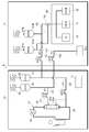
- FIG. 1 is an explanatory diagram showing an outline of the configuration of the blood processing system 1 according to the present embodiment.
- the blood processing system 1 is for performing, for example, a continuous gradual blood purification process.
- a blood processing apparatus 10 that performs blood processing on a patient, and a treatment liquid such as a dialysate or a replacement fluid is applied to the blood processing apparatus 10.
- a treatment liquid supply device 11 for supplying and replenishing and a control device 12 (including a drainage control device) are provided.
- the blood processing apparatus 10 has a blood processing circuit 21 that supplies the patient's blood to the blood purifier 20 and returns it to the patient.
- the blood processing circuit 21 has a blood supply circuit 22 for supplying the patient's blood to the blood purifier 20 and a blood return circuit 23 for returning the blood from the blood purifier 20 to the patient.
- the blood treatment apparatus 10 includes a treatment liquid supply circuit 24 that performs at least one of supply of a replacement fluid to the blood supply circuit 22 and / or the blood return circuit 23 and supply of dialysate to the blood purifier 20, blood A drain circuit 25 is provided for draining the waste liquid generated by the purifier 20.
- the blood purifier 20 is, for example, a hollow fiber module incorporating a hollow fiber membrane, and passes waste products or the like in the blood supplied to the primary side 20a of the hollow fiber membrane to the secondary side 20b of the hollow fiber membrane. Thus, blood can be filtered and purified.
- the blood supply circuit 22 is connected to the inlet of the primary side 20a of the blood purifier 20 from, for example, a needle portion (not shown) punctured by the patient.
- the blood supply circuit 22 is provided with a pump 30 and can supply the patient's blood to the blood purifier 20 at a predetermined flow rate.
- a so-called tube pump for handling a tube constituting a circuit and sending a liquid in the tube is used.
- the blood return circuit 23 is connected to the needle part (not shown) from the outlet of the primary side 20a of the blood purifier 20.
- the treatment liquid supply circuit 24 is connected from the first storage container 40 to either the blood supply circuit 22 and / or the blood return circuit 23 or the secondary side 20 b of the blood purifier 20.
- the treatment liquid supply circuit 24 is a type of blood purification treatment, such as continuous gradual hemofiltration (CHF), continuous dialysis hemodialysis (CHD), continuous dialysis hemodialysis (CHDF). According to continuous (HemoDiaFiltration), it can be selected whether to connect to the blood supply circuit 22 and / or the blood return circuit 23, to the blood purifier 20, or to a plurality of them.
- CHF continuous gradual hemofiltration
- CHD continuous dialysis hemodialysis
- CHDF continuous dialysis hemodialysis
- the treatment liquid supply circuit 24 is provided with a tube pump 41 as a supply pump, and can supply the dialysis liquid and the replacement liquid treatment liquid in the first storage container 40 at a predetermined flow rate.
- the first storage container 40 is provided with a first weighing scale 42 for measuring the weight of the container 40.
- the drain circuit 25 is connected to the drain container 50 from the secondary side 20b of the blood purifier 20.
- the drainage circuit 25 is provided with a tube pump 51 as a drainage pump, and the drainage of the blood purifier 20 can be discharged to the drainage container 50 at a predetermined flow rate.
- the drainage container 50 is provided with a third weigh scale 52 that measures the weight of the container 50.
- the therapeutic liquid supply apparatus 11 includes a therapeutic liquid generation unit 60 that generates a therapeutic liquid, a therapeutic liquid supply circuit 62 that supplies the therapeutic liquid generated by the therapeutic liquid generation unit 60 to the second storage container 61, a first A therapeutic liquid replenishment circuit 63 for replenishing the first storage container 40 of the blood processing apparatus 10 with the therapeutic liquid in the second storage container 61 is provided.
- the treatment liquid generation unit 60 has, for example, a water supply source 70, an A raw solution supply source 71, and a B raw solution supply source 72, and can mix these liquids at a predetermined ratio to generate a treatment liquid.
- a water supply source 70 for example, reverse osmosis filtered water, ultrafiltered water, or the like is used.
- a stock solution for example, a solution stock solution not containing sodium bicarbonate is used
- B stock solution for example, a solution stock solution containing sodium bicarbonate is used.
- the therapeutic liquid supply circuit 62 is connected from the therapeutic liquid generator 60 to the second storage container 61, and the therapeutic liquid replenishment circuit 63 is connected from the second storage container 61 to the therapeutic liquid supply circuit 24 of the blood processing apparatus 10. ing.
- the therapeutic liquid supply circuit 62 is provided with therapeutic liquid blocking means 64 such as an on-off valve or a tube pump.
- the treatment liquid replenishment circuit 63 is provided with a tube pump 80 and can supply the treatment liquid in the second storage container 61 to the treatment liquid supply circuit 24 at a predetermined flow rate.
- the second storage container 61 is provided with a second weigh scale 81 that measures the weight of the container 61.
- the control device 12 is a computer that controls the entire operation of the blood processing system 1, and controls the operations of the tube pumps 30, 41, 51, 80, the treatment liquid closing means 64, etc., to replenish the blood treatment and treatment liquid. Can be executed.
- the control device 12 has a program for correcting the flow rate error of the tube pump 41 based on the measurement results by the weight scales 42 and 81 and controlling the flow rate of the treatment liquid supplied to the blood processing circuit 21 as described later.
- the blood processing apparatus 10 and the treatment liquid supply apparatus 11 may each have a control computer, and the control apparatus 12 may control the whole by wired or wireless communication.
- a continuous gradual blood purification process is performed on a patient.
- CHF continuous gradual blood filtration
- the patient's blood is supplied to the blood purifier 20 through the blood supply circuit 22 by the tube pump 30. Waste products and the like removed from the blood through the membrane in the blood purifier 20 are discharged to the drainage container 50 through the drainage circuit 25 by the tube pump 51.
- the tube pump 41 supplies the replacement fluid in the first storage container 40 to the blood supply circuit 22 and / or the blood return circuit 23 through the treatment liquid supply circuit 24.
- the blood purified by the blood purifier 20 is returned to the patient through the blood return circuit 23.
- the dialysis fluid in the first storage container 40 is supplied to the secondary side 20 b of the membrane of the blood purifier 20 by the tube pump 41.
- CHDF continuous gradual hemodialysis
- the treatment liquid in the second storage container 61 is appropriately supplied to the first storage container 40 of the blood processing apparatus 10 and replenished. To do.
- the tube pump 80 supplies the treatment liquid supply circuit 24 of the blood processing apparatus 10 through the treatment liquid replenishment circuit 63.
- the therapeutic liquid supplied to the therapeutic liquid supply circuit 24 is mainly supplied to and stored in the first storage container 40, and in some cases, it is partially stored in at least one of the blood supply circuit 22, the blood return circuit 23, or the blood purifier 20. Supplied directly.
- the therapeutic liquid is generated by the therapeutic liquid generation unit 60 when the supply of the therapeutic liquid is stopped, and is stored in the second storage container 61 in advance.
- the treatment liquid supply blocking means 64 is closed, and the treatment liquid is not replenished to the second storage container 61.
- the therapeutic liquid supply means from the second storage container 61 to the first storage container 40 may be a liquid supply using a valve and a drop instead of the tube pump 80.
- the replenishment method using the head when the tube pump 41 operates at a high flow rate, the replenishment of the treatment liquid due to the head is not in time, and the treatment liquid in the first storage container 40 is quickly emptied, so that stable treatment is possible. The liquid cannot be supplied.
- it is preferable to use the tube pump 80 because the use of a head and a valve takes a place and the size of the entire blood processing system 1 cannot be increased.
- the control device 12 During the blood purification process, the control device 12 strictly controls the supply flow rate of the treatment liquid to the blood processing circuit 21. For example, during the blood purification process, the weight of the first storage container 40 is continuously measured by the first weighing scale 42, and the weight of the second storage container 61 is continuously measured by the second weighing scale 81. . These measurement results are output to the control device 12, and are supplied by the tube pump 41 from the change amount of the sum of the weight of the first storage container 40 and the weight of the second storage container 61. The actual flow rate Q1 of the treatment liquid is calculated.
- the control device 12 corrects a flow rate error p1 (Q2-Q1) between the actual flow rate Q1 of the tube pump 41 and a preset target flow rate Q2, for example, as shown in FIG.
- the flow rate error p1 is corrected by increasing the output of the tube pump 41 by the flow rate error.
- the control device 12 performs feedback control of the tube pump 41 continuously or intermittently, and strictly controls the flow rate of the treatment liquid supplied to the blood processing circuit 21.
- the control device 12 strictly controls the drainage flow rate from the blood purifier 20 of the blood processing circuit 21 to the drainage container 50.
- the weight of the drainage container 50 is continuously measured by the third weighing scale 52 during the blood purification process. This measurement result is output to the control device 12, and the control device 12 calculates the actual flow rate Q3 of the drainage discharged by the tube pump 51 from the amount of change in the weight of the drainage container 50.
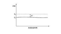
- the control device 12 corrects a flow rate error P2 (Q4-Q3) between the actual flow rate Q3 of the tube pump 51 and a preset target flow rate Q4 as shown in FIG. 3, for example.
- the flow rate error p2 is corrected by increasing the output of the tube pump 51 by the flow rate error.
- the control device 12 performs feedback control of the tube pump 51 continuously or intermittently, and strictly controls the flow rate of the drainage discharged from the blood purifier 20.
- the weight of the first storage container 40 and the weight of the second storage container 61 are measured, the actual flow rate Q1 of the tube pump 41 is calculated from the change amount ⁇ M of the sum, and the tube pump 41 is controlled to correct the flow rate error p1 between the actual flow rate Q1 and the target flow rate Q2, so that even if the first storage container 40 of the blood processing apparatus 10 is replenished with therapeutic liquid during blood processing, the treatment of the storage container
- the flow rate control of the tube pump 41 based on the decrease in the liquid can be performed. Therefore, the supply flow rate of the therapeutic liquid to the blood processing circuit 21 can be strictly controlled while replenishing the first storage container 40 of the blood processing apparatus 10 with the therapeutic liquid during blood processing.
- the blood processing system 1 further includes an external drain circuit 100 that discharges the drainage stored in the drainage container 50 to the outside, and appropriately drains during blood processing.
- the drainage of the container 50 may be discharged to the outside.
- the external drainage circuit 100 is connected from the drainage circuit 25 to the drainage unit 110 of the treatment liquid supply apparatus 11 and includes a tube pump 111.
- the tube pump 111 is activated, and the drainage of the drainage container 50 is drained through the external drainage circuit 100. To be discharged.
- the tube pump 51 of the drain circuit 25 continues to operate.
- the tube pump 111 is stopped and the drainage of the drainage is stopped.
- the flow control of the tube pump 51 of the drain circuit 25 is performed as follows. As described above, when the drainage of the drainage container 50 is not discharged through the external drainage circuit 100, the actual amount of the tube pump 51 is calculated from the amount of change in the weight of the drainage container 50 measured by the third weighing scale 52. The flow rate Q3 is calculated, and the tube pump 51 is controlled to correct the flow rate error p2 between the actual flow rate Q3 and the target flow rate Q4. Then, as shown in FIG. 5, while the drainage of the drainage container 50 is being discharged through the external drainage circuit 100, the tube is corrected using the correction value of the flow rate error p2 immediately before the discharge to the outside is started. The pump 51 is controlled.
- the correction value of the flow rate error p2 immediately before the drainage of the drainage container 50 is started is c1
- the correction value c1 of the flow rate error is maintained during drainage.
- the measurement of the weight of the drainage container 50 by the third weighing scale 52 is stopped.
- the measurement of the weight of the drainage container 50 by the third weighing scale 52 is started again, and the actual flow rate Q3 of the tube pump 51 is calculated based on the weight,
- the tube pump 51 is controlled to correct the flow rate error p2 between the actual flow rate Q3 and the target flow rate Q4.
- the blood processing can be continuously performed for a long period of time. Further, if the blood treatment is continued for a long time until the drainage container 50 has sufficiently accumulated the drainage, the actual flow rate Q3 of the tube pump 51 is stabilized, and the correction value c1 of the flow rate error p2 is stabilized.
- the tube pump 51 in the liquid is controlled using the correction value c1 of the flow rate error p2 immediately before the discharge of the drainage is started. By doing so, the drainage flow rate from the blood purifier 20 can be strictly controlled while draining the drainage during the blood treatment. Therefore, long-term blood treatment by the blood purifier 20 is appropriately performed.
- the blood processing system 1 includes a plurality of, for example, two second storage containers 61 as shown in FIG. 6, and the second storage containers 61A and 61B are provided with the second storage containers 61A and 61B.
- Weigh scales 81A and 81B are provided, and the first storage container 40 is replenished with the treatment liquid from one second storage container 61A and 61B sequentially selected from the plurality of second storage containers 61A and 61B. You may do it.
- the treatment liquid supply circuit 62 is branched in the middle so as to be connected to each of the second storage containers 61A and 61B.
- a three-way valve 120 is provided at this branch point.
- the treatment liquid replenishment circuit 63 is branched in the middle so as to be connected to each of the second storage containers 61A and 61B.
- a three-way valve 121 is provided at this branch point.
- the blood treatment it is selected from which second storage container 61A, 61B the first storage container 40 is replenished with the treatment liquid, and the unselected second storage containers 61A, 61B include The therapeutic liquid is replenished from the therapeutic liquid generation unit 60.
- the treatment liquid is replenished from the second storage container 61A to the first storage container 40 when the treatment liquid is replenished, and the second storage container 61B includes The therapeutic liquid is appropriately supplemented from the therapeutic liquid generation unit 60.
- the treatment liquid is replenished from the second storage container 61B to the first storage container 40 when the treatment liquid is replenished, and the second storage container 61A
- the therapeutic liquid is appropriately supplemented from the therapeutic liquid generation unit 60.
- the selection of the second storage container 61A and the second storage container 61B is performed alternately.
- the flow rate control of the tube pump 41 of the treatment liquid supply circuit 24 is performed by adding the weight of the second storage container 61 to which the first storage container 40 is replenished (selected) and the first storage container 40.
- the actual flow rate Q1 of the tube pump 41 is calculated from the amount of change in the total with the weight of the storage container 40, and the tube pump 41 is controlled to correct the flow rate error p1 between the actual flow rate Q1 and the target flow rate Q2.
- the blood processing system 1 has a plurality of second storage containers 61, replenishment of the treatment liquid to the first storage container 40, and the supply of the treatment liquid to the second storage container 61. Since the replenishment can be performed alternately, the flow rate of the tube pump 80 only needs to be equal to or higher than the flow rate required for the tube pump 41, so that the pump can be downsized. In addition, it is possible to strictly control the supply flow rate of the treatment liquid of the tube pump 41 at that time. In addition, the number of the 2nd storage containers 61 in this Embodiment is not restricted to two, It can select arbitrarily.
- the blood processing system 1 includes the blood processing apparatus 10 and the treatment liquid supply apparatus 11, but they may be independent or integrated.
- the treatment liquid supply is not performed from the treatment liquid supply apparatus 11 but by connecting an existing prepared treatment liquid bag instead of the first storage container 40, thereby supplying the treatment liquid supply apparatus. Treatment may be performed without using 11. Therefore, in order to give flexibility to the embodiment of treatment, the first storage container 40 is installed on the blood processing apparatus 10 side, the second storage container 61 is installed on the treatment liquid supply apparatus 11 side, and the blood processing apparatus 10
- the treatment liquid supply device 11 is preferably configured independently.
- the blood processing apparatus 10 already exists in the market, and a large investment is required when developing in an integrated type. Therefore, by designing the blood processing apparatus 10 and the treatment liquid supply apparatus 11 as independent devices, development costs can be suppressed and smooth introduction into the existing market becomes possible.
- the respective circuits are connected to each other through the treatment liquid replenishment circuit 63 and the treatment liquid supply circuit 24.
- a luer connector or the like can be used for connection, but there is no particular limitation as long as each circuit can be connected.
- the treatment liquid replenishment circuit 63 and the treatment liquid supply circuit 24 can be directly connected or connected via the first storage container 40, but the treatment liquid is connected to the first storage container 40. There is no particular limitation as long as it can be supplied.
- the treatment liquid replenishment circuit 63 when the treatment liquid replenishment circuit 63 is not connected in advance to the connection portion with respect to the treatment liquid supply circuit 24, a clamp, a check valve, a needleless mixed injection tube, or the like may be arranged at the connection portion to prevent leakage of the treatment liquid. .
- the blood processing apparatus 10 and the treatment liquid supply apparatus 11 are configured independently, it is necessary to control the measurement results of the first weight scale 41 and the second weight scale 81 by sharing each other. There is. For this purpose, it is necessary that the blood processing apparatus 10 and the treatment liquid supply apparatus 11 are electrically linked.
- the means may be a physical connection such as an RS232 cable, an RS422 cable, a LAN cable, or a USB cable, or Blue.
- a wireless signal such as a tooth (registered trademark) or an infrared ray can be used, but any signal can be used as long as it can transmit information necessary for control, and the signal is not particularly limited.
- the second storage container 61 is on the treatment liquid supply device 11 side, but is not particularly limited to this, and may be on the blood processing device 10 side.
- the circuit configuration of the blood processing system 1 is not limited to this.
- the pumps 41 and 51 to be controlled may not be tube pumps.
- the flow rate control of the tube pump 41 of the treatment liquid supply circuit 24 is performed and the flow rate control of the tube pump 51 of the drainage circuit 25 is performed.
- Good That is, while the drainage of the drainage container 50 is not discharged to the outside through the external drainage circuit 100, the actual flow rate of the tube pump 51 is calculated from the amount of change in the weight of the drainage container 50 measured by the weigh scale 52. Q3 is calculated, the tube pump 51 is controlled to correct the flow rate error p2 between the actual flow rate Q3 and the target flow rate Q4, and while the drainage of the drainage container 50 is being discharged to the outside through the external drainage circuit 100.
- the tube pump 51 may be controlled using the correction value c1 of the flow rate error p2 immediately before the discharge of the drainage is started.
- the blood processing system of the present invention can also be applied to the case where a therapeutic liquid is supplied to a blood processing apparatus other than the sustained release type.
- the present invention is useful in providing a blood processing system that strictly controls the supply flow rate of the therapeutic liquid to the blood processing circuit while replenishing the therapeutic liquid in the storage container of the blood processing apparatus during blood processing.
Landscapes
- Health & Medical Sciences (AREA)
- Heart & Thoracic Surgery (AREA)
- Vascular Medicine (AREA)
- Life Sciences & Earth Sciences (AREA)
- Engineering & Computer Science (AREA)
- Anesthesiology (AREA)
- Biomedical Technology (AREA)
- Hematology (AREA)
- Animal Behavior & Ethology (AREA)
- General Health & Medical Sciences (AREA)
- Public Health (AREA)
- Veterinary Medicine (AREA)
- Cardiology (AREA)
- Emergency Medicine (AREA)
- Urology & Nephrology (AREA)
- External Artificial Organs (AREA)
Abstract
血液処理システム1は、患者の血液を血液浄化器20に供給し患者に戻す血液処理回路21と、第1の貯留容器40に貯留された透析液又は補液の治療液を、チューブポンプ41により血液処理回路21に供給する治療液供給回路24と、第2の貯留容器61に貯留された治療液を第1の貯留容器40に補充する治療液補充回路63と、第1の重量計42と、第2の重量計81と、第1の重量計42により測定された第1の貯留容器40の重量と第2の重量計81により測定された第2の貯留容器61の重量との総和の変化量から、チューブポンプ41の実流量を算出し、チューブポンプ41を制御して実流量と目標流量との流量誤差を補正する制御装置12と、を有する。
Description
本発明は、血液処理システムに関する。
例えば急性腎不全等の重篤患者に対する治療法の一つとして、体外循環により持続的に血液の浄化を行う持続緩除式血液濾過療法がある。この治療は、血液処理装置で行われ、血液処理装置は、患者の血液を血液浄化器に供給し浄化後に患者に戻す血液処理回路と、血液処理回路で使用される治療液を血液処理回路に供給する治療液供給回路を有している。治療液には、患者の体液バランスを維持するため、血液処理回路の血液に供給される補液や、患者の血液から老廃物を除去するために血液浄化器に供給される透析液がある。治療液は、治療液供給回路の貯留容器に貯留されており、供給ポンプにより貯留容器から血液処理回路に供給される。
上述の治療液の供給流量は、患者の体液量や体液成分に影響を与えるため、厳格に制御する必要がある。そこで、血液処理装置では、貯留容器に重量計を設け、重量計により測定された貯留容器の重量の変化量から、供給ポンプの実流量を算出し、当該実流量から供給ポンプを厳格に制御することが考えられている。
ところで、持続緩除式血液濾過療法では、血液処理装置において長時間連続して血液を処理するため、この血液処理に使用される透析液や補液の治療液を血液処理装置の貯留容器に補充できるとよい。そこで、血液処理装置に透析液作成装置を接続し、当該透析液作成装置で透析液を作成して血液浄化装置に供給することが提案されている(特許文献1参照)。
しかしながら、上述のような透析液作成装置を用いて血液処理中に貯留容器に治療液を補充しようとすると、貯留容器の重量が、他から補充された治療液により変化し、上述した貯留容器の重量に基づく供給ポンプの流量の制御を行えなくなる。よって、血液処理を行いながら、貯留容器に治療液を補充することは現実的には困難であった。
本発明はかかる点に鑑みてなされたものであり、血液処理中に血液処理装置の貯留容器に治療液を補充しながら、血液処理回路への治療液の供給流量を厳格に制御可能な血液処理システムを提供することをその目的とする。
上記目的を達成するため発明者らが鋭意研究した結果、治療液供給回路の貯留容器と治療液補充回路の貯留容器にそれぞれ重量計を設け、治療液供給回路の貯留容器の重量と治療液補充回路の貯留容器の重量の総和の変化量から、供給ポンプを制御することで、血液処理中に血液処理装置の貯留容器に治療液を補充しながら、血液処理回路への治療液の供給流量を厳格に制御できることを見出し、本発明に至った。すなわち、本発明の一例として下記(1)~(7)を提供する。
(1)血液浄化器を有し、血液を血液浄化器に供給し、浄化された血液を当該血液浄化器から回収する血液処理回路と、第1の貯留容器に貯留された、前記血液処理回路で使用される治療液を、供給ポンプにより前記血液処理回路に供給する治療液供給回路と、第2の貯留容器に貯留された治療液を前記第1の貯留容器に補充する治療液補充回路と、前記第1の貯留容器の重量を測定する第1の重量計と、前記第2の貯留容器の重量を測定する第2の重量計と、前記第1の重量計により測定された前記第1の貯留容器の重量と前記第2の重量計により測定された前記第2の貯留容器の重量との総和の変化量から、前記供給ポンプの実流量を算出し、当該実流量に基づいて前記供給ポンプを制御する制御装置と、を有する、血液浄化システム。
(2)前記制御装置は、前記治療液補充回路及び前記治療液供給回路に外部から新たな治療液が導入されない状態において、前記第1の重量計により測定された前記第1の貯留容器の重量と前記第2の重量計により測定された前記第2の貯留容器の重量との総和の変化量から、前記供給ポンプの実流量を算出する、(1)に記載の血液浄化システム。
(3)前記制御装置は、前記実流量と前記供給ポンプの目標流量との流量誤差を算出し、当該流量誤差を補正する、(1)又は(2)に記載の血液浄化システム。
(4)前記血液浄化器で生じる排液を排液ポンプにより排液容器に排出する排液回路と、前記排液容器に貯留された排液を外部に排出する外部排液回路と、前記排液容器の重量を測定する第3の重量計と、前記排液容器の排液が前記外部排液回路から外部に排出されていない間には、前記第3の重量計により測定された前記排液容器の重量の変化量から、前記排液ポンプの実流量を算出し、前記排液ポンプを制御して前記実流量と目標流量との流量誤差を補正し、前記排液容器の排液が前記外部排液回路から外部に排出されている間は、当該外部への排出が開始される直前の前記流量誤差の補正値を用いて前記排液ポンプを制御する排液制御装置と、をさらに有する、(1)~(3)のいずれかに記載の血液浄化システム。
(5)前記第2の貯留容器を複数備え、当該第2の貯留容器毎に前記第2の重量計が設けられ、前記複数の第2の貯留容器の中から順次選択される一つの第2の貯留容器から前記第1の貯留容器に治療液が補充され、前記制御装置は、前記第1の貯留容器に治療液を補充している前記第2の貯留容器の重量と前記第1の貯留容器の重量との総和の変化量から、前記供給ポンプの実流量を算出し、当該実流量に基づいて前記供給ポンプを制御する、(1)~(4)のいずれかに記載の血液浄化システム。
(6)治療液を生成する治療液生成部と、前記治療液生成部で生成された治療液を前記第2の貯留容器に供給して貯留する治療液回路と、をさらに有する、(1)~(5)のいずれかに記載の血液浄化システム。
(7)血液を血液浄化器に供給し、浄化された血液を当該血液浄化器から回収する血液処理回路と、前記血液浄化器で生じる排液を排液ポンプにより排液容器に排出する排液回路と、前記排液容器に貯留された排液を外部に排出する外部排液回路と、前記排液容器の重量を測定する重量計と、前記排液容器の排液が前記外部排液回路から外部に排出されていない間は、前記重量計により測定された前記排液容器の重量の変化量から、前記排液ポンプの実流量を算出し、前記排液ポンプを制御して前記実流量と目標流量との流量誤差を補正し、前記排液容器の排液が前記外部排液回路から外部に排出されている間は、当該排液の排出が開始される直前の前記流量誤差の補正値を用いて前記排液ポンプを制御する排液制御装置と、を有する、血液浄化システム。
本発明によれば、血液処理中に血液処理装置の貯留容器に治療液を補充しながら、血液処理回路への治療液の供給流量を厳格に制御できるので、持続緩除式の血液浄化処理などの長時間の血液処理を実現できる。
以下、図面を参照して、本発明の好ましい実施の形態について説明する。なお、以下の実施の形態は、本発明を説明するための例示であり、本発明はその実施の形態のみに限定されるものではない。同一の要素には同一の符号を付し、重複する説明は省略する。また、図面中、上下左右等の位置関係は、特に断らない限り、図面に示す位置関係に基づくものとする。さらに、図面の寸法比率は、図示の比率に限定されるものではない。
図1は、本実施の形態に係る血液処理システム1の構成の概略を示す説明図である。血液処理システム1は、例えば持続緩除式の血液浄化処理を行うためのものであり、患者に対して血液処理を行う血液処理装置10と、血液処理装置10に透析液や補液の治療液を供給し補充する治療液供給装置11と、制御装置12(排液制御装置を含む)を備えている。
血液処理装置10は、患者の血液を血液浄化器20に供給し患者に戻す血液処理回路21を有している。血液処理回路21は、患者の血液を血液浄化器20に供給するための血液供給回路22と、血液浄化器20から患者に血液を戻すための血液返還回路23を有している。
また、血液処理装置10は、血液供給回路22および/又は血液返還回路23への補液の供給、又は血液浄化器20への透析液の供給の少なくともいずれかを行う治療液供給回路24と、血液浄化器20で生成される排液を排出するための排液回路25を有している。
血液浄化器20は、例えば中空糸膜を内蔵した中空糸モジュールであり、中空糸膜の一次側20aに供給された血液の中の老廃物等を、中空糸膜の二次側20bに通過させて、血液を濾過し浄化することができる。
血液供給回路22は、例えば患者に穿刺される針部(図示せず)から血液浄化器20の一次側20aの入口に接続されている。血液供給回路22には、ポンプ30が設けられ、患者の血液を所定の流量で血液浄化器20に供給できる。ポンプ30には、例えば回路を構成するチューブを扱いてチューブ内の液体を送るいわゆるチューブポンプが用いられている。
血液返還回路23は、血液浄化器20の一次側20aの出口から針部(図示せず)に接続されている。
治療液供給回路24は、第1の貯留容器40から血液供給回路22および/又は血液返還回路23又は血液浄化器20の二次側20bのいずれかに接続されている。治療液供給回路24は、血液浄化処理の種類、例えば持続緩除式血液濾過(CHF:Continuous HemoFiltractrion)、持続緩除式血液透析(CHD:Continuous HemoDiaFiltration)、持続緩除式血液濾過透析(CHDF:continuous HemoDiaFiltration)に応じて血液供給回路22および/又は血液返還回路23に接続するか、血液浄化器20に接続するか或いはそれら複数に接続するかを選択できる。
治療液供給回路24には、供給ポンプとしてのチューブポンプ41が設けられ、第1の貯留容器40の透析液や補液の治療液を所定の流量で供給できる。第1の貯留容器40には、当該容器40の重量を測定する第1の重量計42が設けられている。
排液回路25は、血液浄化器20の二次側20bから排液容器50に接続されている。排液回路25には、排液ポンプとしてのチューブポンプ51が設けられ、血液浄化器20の排液を所定の流量で排液容器50に排出できる。排液容器50には、当該容器50の重量を測定する第3の重量計52が設けられている。
治療液供給装置11は、治療液を生成する治療液生成部60と、治療液生成部60で生成された治療液を第2の貯留容器61に供給するための治療液供給回路62と、第2の貯留容器61の治療液を血液処理装置10の第1の貯留容器40に補充するための治療液補充回路63を備えている。
治療液生成部60は、例えば水供給源70と、A原液供給源71と、B原液供給源72を有し、それらの液体を所定の割合で混合して治療液を生成できる。水供給源70の水としては、例えば逆浸透濾過水、限外濾過水等が用いられる。A原液には、例えば重炭酸ナトリウムを含まない溶液原液が用いられ、B原液には、例えば重炭酸ナトリウムを含む溶液原液が用いられる。
治療液供給回路62は、治療液生成部60から第2の貯留容器61に接続され、治療液補充回路63は、第2の貯留容器61から血液処理装置10の治療液供給回路24に接続されている。治療液供給回路62には、開閉弁やチューブポンプなどの治療液閉塞手段64が設けられている。治療液補充回路63には、チューブポンプ80が設けられ、第2の貯留容器61の治療液を所定の流量で治療液供給回路24に供給できる。第2の貯留容器61には、当該容器61の重量を測定する第2の重量計81が設けられている。
制御装置12は、血液処理システム1全体の動作を制御するコンピュータであり、チューブポンプ30、41、51、80や治療液閉塞手段64等の動作を制御して、血液処理や治療液の補充を実行できる。例えば制御装置12は、後述するように重量計42、81による測定結果に基づいてチューブポンプ41の流量誤差を補正し、血液処理回路21に供給される治療液の流量を制御するプログラムを有する。血液処理装置10と治療液供給装置11はそれぞれ制御コンピュータを有し、有線又は無線による通信により、制御装置12が全体を制御してもよい。
次に、以上のように構成された血液処理システム1の動作を説明する。
図1に示す血液処理装置10では、患者に対する持続緩除式の血液浄化処理が行われる。例えば持続緩除式血液濾過(CHF)治療が行われる場合、患者の血液がチューブポンプ30により血液供給回路22を通じて血液浄化器20に供給される。血液浄化器20において血液から膜を通じて除去された老廃物等は、チューブポンプ51により排液回路25を通じて排液容器50に排出される。また、チューブポンプ41により第1の貯留容器40の補液が治療液供給回路24を通じて血液供給回路22及び/又は血液返還回路23に供給される。血液浄化器20で浄化された血液は、血液返還回路23を通じて患者に戻される。また、持続緩除式血液透析(CHD)治療が行われる場合には、チューブポンプ41により第1の貯留容器40の透析液が血液浄化器20の膜の二次側20bに供給される。持続緩除式血液濾過透析(CHDF)治療が行われる場合には、チューブポンプ41により補液が血液供給回路22及び/又は血液返還回路23に供給され、透析液が血液浄化器20に供給される。
また、治療液供給装置11では、血液処理装置10で血液浄化処理が行われている間、適宜第2の貯留容器61の治療液を血液処理装置10の第1の貯留容器40に供給し補充する。このとき、チューブポンプ80により治療液補充回路63を通じて血液処理装置10の治療液供給回路24に供給される。治療液供給回路24に供給された治療液は、主に第1の貯留容器40に供給され貯留され、場合によって一部血液供給回路22、血液返還回路23又は血液浄化器20の少なくともいずれかに直接供給される。なお、治療液は、治療液供給停止時に治療液生成部60で生成され、予め第2の貯留容器61に貯留されている。治療液供給中は、治療液供給閉塞手段64が閉鎖されており、治療液は第2の貯留容器61に補充されない。なお、例えば第2の貯留容器61から第1の貯留容器40への治療液供給手段はチューブポンプ80の代わりにバルブと落差を用いた送液なども考えられる。しかしながら落差を用いた補充方法の場合、チューブポンプ41が高流量で作動すると、落差よる治療液の補充が間に合わず、第1の貯留容器40内の治療液が早急に空となるため安定した治療液の供給を行うことができない。加えて落差とバルブを用いると場所をとり、血液処理システム1全体の大型化が免れないため、チューブポンプ80を用いることが好ましい。
血液浄化処理中、制御装置12により、血液処理回路21への治療液の供給流量が厳格に制御される。例えば血液浄化処理中、第1の重量計42により第1の貯留容器40の重量が継続的に測定され、第2の重量計81により第2の貯留容器61の重量が継続的に測定される。これらの測定結果は、制御装置12に出力され、制御装置12において、第1の貯留容器40の重量と第2の貯留容器61の重量との総和の変化量から、チューブポンプ41により供給されている治療液の実流量Q1を算出する。例えば、第1の貯留容器40の重量と第2の貯留容器61の重量の総和Mの変化量ΔMから、式Q1=ΔM/測定時間により、実流量Q1を算出する。次に、制御装置12は、例えば図2に示すような、当該チューブポンプ41の実流量Q1と、予め設定されている目標流量Q2との流量誤差p1(Q2-Q1)を補正する。具体的には例えばチューブポンプ41の出力を流量誤差分だけ上げて流量誤差p1を補正する。制御装置12は、このチューブポンプ41のフィードバック制御を連続的或いは断続的に行い、血液処理回路21に供給される治療液の流量を厳格に制御する。
また、血液浄化処理中、制御装置12により、血液処理回路21の血液浄化器20から排液容器50への排液流量が厳格に制御される。例えば血液浄化処理中、第3の重量計52により排液容器50の重量が継続的に測定される。この測定結果は、制御装置12に出力され、制御装置12において、排液容器50の重量の変化量から、チューブポンプ51により排出されている排液の実流量Q3を算出する。次に、制御装置12は、例えば図3に示すような、チューブポンプ51の実流量Q3と、予め設定されている目標流量Q4との流量誤差P2(Q4-Q3)を補正する。具体的には例えばチューブポンプ51の出力を流量誤差分だけ上げて流量誤差p2を補正する。制御装置12は、このチューブポンプ51のフィードバック制御を連続的或いは断続的に行い、血液浄化器20から排出される排液の流量を厳格に制御する。
本実施の形態によれば、第1の貯留容器40の重量と第2の貯留容器61の重量を測定し、その総和の変化量ΔMから、チューブポンプ41の実流量Q1を算出し、チューブポンプ41を制御して実流量Q1と目標流量Q2との流量誤差p1を補正するので、血液処理中に血液処理装置10の第1の貯留容器40に治療液が補充されても、貯留容器の治療液の減少に基づくチューブポンプ41の流量制御を行うことができる。よって、血液処理中に血液処理装置10の第1の貯留容器40に治療液を補充しながら、血液処理回路21への治療液の供給流量を厳格に制御できる。
上記実施の形態において、図4に示すように血液処理システム1が、排液容器50に貯留された排液を外部に排出する外部排液回路100をさらに有し、血液処理中に適宜排液容器50の排液を外部に排出するようにしてもよい。
かかる場合、例えば外部排液回路100は、排液回路25から治療液供給装置11の排液部110に接続され、チューブポンプ111を備えている。そして、血液処理中に排液容器50に所定の閾値以上の排液が溜まった場合には、チューブポンプ111が作動し、排液容器50の排液が外部排液回路100を通じて排液部110に排出される。このとき血液処理が継続されているため、排液回路25のチューブポンプ51は引き続き稼働している。そして、排液容器50の排液が所定量以下に減少すると、チューブポンプ111が停止され、排液の排出が止められる。
このときの排液回路25のチューブポンプ51の流量制御は、次のように行われる。上述のように排液容器50の排液が外部排液回路100を通じて排出されていない時には、第3の重量計52により測定された排液容器50の重量の変化量から、チューブポンプ51の実流量Q3を算出し、チューブポンプ51を制御して実流量Q3と目標流量Q4との流量誤差p2を補正する。そして、図5に示すように排液容器50の排液が外部排液回路100を通じて排出されている間は、当該外部への排出が開始される直前の流量誤差p2の補正値を用いてチューブポンプ51を制御する。すなわち、排液容器50の排液の排出が開始される直前の流量誤差p2の補正値がc1である場合には、排液中その流量誤差の補正値c1が維持される。排液の排出中は第3の重量計52による排液容器50の重量の計測は止められる。そして、排液容器50の排液が終了すると、再び第3の重量計52による排液容器50の重量の計測が開始され、当該重量に基づいて、チューブポンプ51の実流量Q3を算出し、チューブポンプ51を制御して実流量Q3と目標流量Q4との流量誤差p2を補正する。
この実施の形態によれば、血液処理中に排液容器50の排液を排出できるので、血液処理を長期間継続して行うことができる。また、排液容器50に排液が十分に溜まるまで血液処理を長く継続していると、チューブポンプ51の実流量Q3が安定し、その流量誤差p2の補正値c1が安定することから、排液中のチューブポンプ51の制御を、排液の排出が開始される直前の流量誤差p2の補正値c1を用いて行う。こうすることにより、血液処理中に排液の排出を行いながら、血液浄化器20からの排液の排出流量を厳格に制御できる。よって、血液浄化器20による長期間の血液処理が適切に行われる。
次に、以上の実施の形態において、血液処理システム1は、図6に示すように第2の貯留容器61を複数、例えば2つ備え、その第2の貯留容器61A、61B毎に第2の重量計81A、81Bが設けられ、複数の第2の貯留容器61A、61Bの中から順次選択される一つの第2の貯留容器61A、61Bから第1の貯留容器40に治療液が補充されるようにしてもよい。
かかる場合、治療液供給回路62は、各第2の貯留容器61A、61Bにそれぞれ接続されるように途中で分岐している。この分岐点には、例えば三方弁120が設けられる。また、治療液補充回路63は、各第2の貯留容器61A、61Bにそれぞれ接続されるように途中で分岐している。この分岐点には、例えば三方弁121が設けられる。
血液処理中は、どちらの第2の貯留容器61A、61Bから第1の貯留容器40に治療液が補充されるか選択されており、選択されていない第2の貯留容器61A、61Bには、治療液生成部60から治療液が補充される。例えば第2の貯留容器61Aが選択されている場合には、治療液の補充時に第2の貯留容器61Aから第1の貯留容器40に治療液が補充され、第2の貯留容器61Bには、適宜治療液生成部60から治療液が補充される。また、第2の貯留容器61Bが選択されている場合には、治療液の補充時に第2の貯留容器61Bから第1の貯留容器40に治療液が補充され、第2の貯留容器61Aには、適宜治療液生成部60から治療液が補充される。この第2の貯留容器61Aと第2の貯留容器61Bの選択が交互に行われる。
そして、治療液供給回路24のチューブポンプ41の流量制御は、第1の貯留容器40に治療液を補充している(選択されている)一方の第2の貯留容器61の重量と第1の貯留容器40の重量との総和の変化量から、チューブポンプ41の実流量Q1を算出し、チューブポンプ41を制御して実流量Q1と目標流量Q2との流量誤差p1を補正する。
この実施の形態によれば、血液処理システム1が複数の第2の貯留容器61を有し、第1の貯留容器40への治療液の補充と、第2の貯留容器61への治療液の補充を交互に行うことができるので、チューブポンプ80の流量をチューブポンプ41に必要とされる流量と同等またはそれ以上であればよいため、ポンプの小型化が可能となる。またそのときのチューブポンプ41の治療液の供給流量の制御も厳格に行うことができる。なお、本実施の形態における第2の貯留容器61の数は、2つに限られず任意に選択できる。
ここで、血液処理システム1は血液処理装置10と治療液供給装置11とから構成されるが、それらは独立していても、一体型であってもよい。しかしながら、治療の実施形態によっては、治療液の供給は治療液供給装置11からではなく、調合された既存の治療液バッグを第1の貯留容器40の代わりに接続することで、治療液供給装置11を用いることなく治療を実施することもある。そのため、治療の実施形態に柔軟性を持たせるために、第1の貯留容器40を血液処理装置10側に、第2の貯留容器61を治療液供給装置11側に設置し、血液処理装置10と治療液供給装置11は独立して構成されていることが好ましい。また、血液処理装置10は市場にすでに存在しており、一体型で開発を行う場合には大きな投資が必要となる。そこで血液処理装置10と治療液供給装置11を独立した機器として設計を行うことで、開発コストを抑えることが可能となると共に、既存の市場へのスムーズな導入が可能となる。血液処理装置10と治療液供給装置11が独立して構成される場合には、それぞれの回路は、治療液補充回路63と治療液供給回路24を連通して接続される。接続は例えばルアーコネクタ等を用いることができるが、それぞれの回路を接続できるものであれば何でもよく、特に限定するものではない。また接続位置としては、治療液補充回路63と治療液供給回路24を直接接続したり、または第1の貯留容器40を介して接続することができるが、治療液を第1の貯留容器40に供給できるものであれば何でもよく、特に限定するものではない。また治療液供給回路24に対する接続部に予め治療液補充回路63が接続されていない場合、治療液の漏れを防ぐために接続部にクランプや逆止弁、ニードルレス混注管などを配置してもよい。また、血液処理装置10と治療液供給装置11が独立して構成される場合には、第1の重量計41と第2の重量計81の測定結果を相互に共有を行って制御をする必要がある。そのためには血液処理装置10と治療液供給装置11が電気的に連動することが必要となるが、その手段は例えばRS232ケーブル、RS422ケーブル、LANケーブル、USBケーブルのような物理的接続や、Blue tooth(登録商標)や赤外線などの無線信号などを挙げることができるが、制御に必要な情報を伝達できるものであれば何でもよく、特に限定するものではない。
ここで、血液処理システム1は血液処理装置10と治療液供給装置11とから構成されるが、それらは独立していても、一体型であってもよい。しかしながら、治療の実施形態によっては、治療液の供給は治療液供給装置11からではなく、調合された既存の治療液バッグを第1の貯留容器40の代わりに接続することで、治療液供給装置11を用いることなく治療を実施することもある。そのため、治療の実施形態に柔軟性を持たせるために、第1の貯留容器40を血液処理装置10側に、第2の貯留容器61を治療液供給装置11側に設置し、血液処理装置10と治療液供給装置11は独立して構成されていることが好ましい。また、血液処理装置10は市場にすでに存在しており、一体型で開発を行う場合には大きな投資が必要となる。そこで血液処理装置10と治療液供給装置11を独立した機器として設計を行うことで、開発コストを抑えることが可能となると共に、既存の市場へのスムーズな導入が可能となる。血液処理装置10と治療液供給装置11が独立して構成される場合には、それぞれの回路は、治療液補充回路63と治療液供給回路24を連通して接続される。接続は例えばルアーコネクタ等を用いることができるが、それぞれの回路を接続できるものであれば何でもよく、特に限定するものではない。また接続位置としては、治療液補充回路63と治療液供給回路24を直接接続したり、または第1の貯留容器40を介して接続することができるが、治療液を第1の貯留容器40に供給できるものであれば何でもよく、特に限定するものではない。また治療液供給回路24に対する接続部に予め治療液補充回路63が接続されていない場合、治療液の漏れを防ぐために接続部にクランプや逆止弁、ニードルレス混注管などを配置してもよい。また、血液処理装置10と治療液供給装置11が独立して構成される場合には、第1の重量計41と第2の重量計81の測定結果を相互に共有を行って制御をする必要がある。そのためには血液処理装置10と治療液供給装置11が電気的に連動することが必要となるが、その手段は例えばRS232ケーブル、RS422ケーブル、LANケーブル、USBケーブルのような物理的接続や、Blue tooth(登録商標)や赤外線などの無線信号などを挙げることができるが、制御に必要な情報を伝達できるものであれば何でもよく、特に限定するものではない。
以上、添付図面を参照しながら本発明の好適な実施の形態について説明したが、本発明はかかる例に限定されない。当業者であれば、特許請求の範囲に記載された思想の範疇内において、各種の変更例または修正例に想到し得ることは明らかであり、それらについても当然に本発明の技術的範囲に属するものと了解される。
例えば以上の実施の形態では、第2の貯留容器61が治療液供給装置11側にあったが、特にこれに限定されるものではなく、血液処理装置10側にあってもよい。血液処理システム1の回路構成はこれに限られない。制御されるポンプ41、51もチューブポンプでなくてもよい。
上記実施の形態では、治療液供給回路24のチューブポンプ41の流量制御を行い、さらに排液回路25のチューブポンプ51の流量制御を行っていたが、チューブポンプ51の流量制御のみを行ってもよい。つまり、排液容器50の排液が外部排液回路100を通じて外部に排出されていない間には、重量計52により測定された排液容器50の重量の変化量から、チューブポンプ51の実流量Q3を算出し、チューブポンプ51を制御して実流量Q3と目標流量Q4との流量誤差p2を補正し、排液容器50の排液が外部排液回路100を通じて外部に排出されている間は、当該排液の排出が開始される直前の流量誤差p2の補正値c1を用いてチューブポンプ51を制御してもよい。また、本発明の血液処理システムは、持続緩除式以外の血液処理装置に治療液を供給する場合にも適用できる。
本発明は、血液処理中に血液処理装置の貯留容器に治療液を補充しながら、血液処理回路への治療液の供給流量を厳格に制御する血液処理システムを提供する際に有用である。
1 血液処理システム
10 血液処理装置
11 治療液供給装置
12 制御装置
20 血液浄化器
21 血液処理回路
40 第1の貯留容器
41 第1の重量計
41 チューブポンプ
50 排液容器
51 チューブポンプ
52 第3の重量計
61 第2の貯留容器
81 第2の重量計
10 血液処理装置
11 治療液供給装置
12 制御装置
20 血液浄化器
21 血液処理回路
40 第1の貯留容器
41 第1の重量計
41 チューブポンプ
50 排液容器
51 チューブポンプ
52 第3の重量計
61 第2の貯留容器
81 第2の重量計
Claims (7)
- 血液浄化器を有し、血液を血液浄化器に供給し、浄化された血液を当該血液浄化器から回収する血液処理回路と、
第1の貯留容器に貯留された、前記血液処理回路で使用される治療液を、供給ポンプにより前記血液処理回路に供給する治療液供給回路と、
第2の貯留容器に貯留された治療液を前記第1の貯留容器に補充する治療液補充回路と、
前記第1の貯留容器の重量を測定する第1の重量計と、
前記第2の貯留容器の重量を測定する第2の重量計と、
前記第1の重量計により測定された前記第1の貯留容器の重量と前記第2の重量計により測定された前記第2の貯留容器の重量との総和の変化量から、前記供給ポンプの実流量を算出し、当該実流量に基づいて前記供給ポンプを制御する制御装置と、を有する、血液浄化システム。 - 前記制御装置は、前記治療液補充回路及び前記治療液供給回路に外部から新たな治療液が導入されない状態において、前記第1の重量計により測定された前記第1の貯留容器の重量と前記第2の重量計により測定された前記第2の貯留容器の重量との総和の変化量から、前記供給ポンプの実流量を算出する、請求項1に記載の血液浄化システム。
- 前記制御装置は、前記実流量と前記供給ポンプの目標流量との流量誤差を算出し、当該流量誤差を補正する、請求項1又は2に記載の血液浄化システム。
- 前記血液浄化器で生じる排液を排液ポンプにより排液容器に排出する排液回路と、
前記排液容器に貯留された排液を外部に排出する外部排液回路と、
前記排液容器の重量を測定する第3の重量計と、
前記排液容器の排液が前記外部排液回路から外部に排出されていない間には、前記第3の重量計により測定された前記排液容器の重量の変化量から、前記排液ポンプの実流量を算出し、前記排液ポンプを制御して前記実流量と目標流量との流量誤差を補正し、前記排液容器の排液が前記外部排液回路から外部に排出されている間は、当該外部への排出が開始される直前の前記流量誤差の補正値を用いて前記排液ポンプを制御する排液制御装置と、をさらに有する、請求項1~3のいずれかに記載の血液浄化システム。 - 前記第2の貯留容器を複数備え、当該第2の貯留容器毎に前記第2の重量計が設けられ、前記複数の第2の貯留容器の中から順次選択される一つの第2の貯留容器から前記第1の貯留容器に治療液が補充され、
前記制御装置は、前記第1の貯留容器に治療液を補充している前記第2の貯留容器の重量と前記第1の貯留容器の重量との総和の変化量から、前記供給ポンプの実流量を算出し、当該実流量に基づいて前記供給ポンプを制御する、請求項1~4のいずれかに記載の血液浄化システム。 - 治療液を生成する治療液生成部と、
前記治療液生成部で生成された治療液を前記第2の貯留容器に供給して貯留する治療液回路と、をさらに有する、請求項1~5のいずれかに記載の血液浄化システム。 - 血液を血液浄化器に供給し、浄化された血液を当該血液浄化器から回収する血液処理回路と、
前記血液浄化器で生じる排液を排液ポンプにより排液容器に排出する排液回路と、
前記排液容器に貯留された排液を外部に排出する外部排液回路と、
前記排液容器の重量を測定する重量計と、
前記排液容器の排液が前記外部排液回路から外部に排出されていない間は、前記重量計により測定された前記排液容器の重量の変化量から、前記排液ポンプの実流量を算出し、前記排液ポンプを制御して前記実流量と目標流量との流量誤差を補正し、前記排液容器の排液が前記外部排液回路から外部に排出されている間は、当該排液の排出が開始される直前の前記流量誤差の補正値を用いて前記排液ポンプを制御する排液制御装置と、を有する、血液浄化システム。
Priority Applications (4)
| Application Number | Priority Date | Filing Date | Title |
|---|---|---|---|
| EP15873288.3A EP3238761B1 (en) | 2014-12-25 | 2015-12-25 | Blood treatment system |
| CN201580070193.0A CN107106755B (zh) | 2014-12-25 | 2015-12-25 | 血液处理系统 |
| EP19161541.8A EP3524289B1 (en) | 2014-12-25 | 2015-12-25 | Blood treatment system |
| JP2016566524A JPWO2016104720A1 (ja) | 2014-12-25 | 2015-12-25 | 血液処理システム |
Applications Claiming Priority (2)
| Application Number | Priority Date | Filing Date | Title |
|---|---|---|---|
| JP2014-262923 | 2014-12-25 | ||
| JP2014262923 | 2014-12-25 |
Publications (1)
| Publication Number | Publication Date |
|---|---|
| WO2016104720A1 true WO2016104720A1 (ja) | 2016-06-30 |
Family
ID=56150732
Family Applications (1)
| Application Number | Title | Priority Date | Filing Date |
|---|---|---|---|
| PCT/JP2015/086265 Ceased WO2016104720A1 (ja) | 2014-12-25 | 2015-12-25 | 血液処理システム |
Country Status (4)
| Country | Link |
|---|---|
| EP (2) | EP3524289B1 (ja) |
| JP (3) | JPWO2016104720A1 (ja) |
| CN (1) | CN107106755B (ja) |
| WO (1) | WO2016104720A1 (ja) |
Cited By (7)
| Publication number | Priority date | Publication date | Assignee | Title |
|---|---|---|---|---|
| JP2020000803A (ja) * | 2018-07-02 | 2020-01-09 | ニプロ株式会社 | 血液浄化装置 |
| WO2020096017A1 (ja) * | 2018-11-08 | 2020-05-14 | 日機装株式会社 | 血液浄化装置 |
| WO2020096018A1 (ja) * | 2018-11-08 | 2020-05-14 | 日機装株式会社 | 血液浄化装置 |
| CN111526900A (zh) * | 2017-10-31 | 2020-08-11 | 耐斯特基尼公司 | 自动体外血液处理装置 |
| JP2020151191A (ja) * | 2019-03-20 | 2020-09-24 | 日機装株式会社 | 血液浄化装置 |
| EP3797803A1 (de) | 2019-09-26 | 2021-03-31 | B. Braun Avitum AG | Blutbehandlungsvorrichtung mit verbesserter beutelgewichtüberwachung |
| WO2024150754A1 (ja) * | 2023-01-12 | 2024-07-18 | ニプロ株式会社 | 血液浄化装置 |
Families Citing this family (11)
| Publication number | Priority date | Publication date | Assignee | Title |
|---|---|---|---|---|
| CN107485742A (zh) * | 2017-09-08 | 2017-12-19 | 重庆山外山血液净化技术股份有限公司 | 血液净化系统及该血液净化系统的管路预充控制方法 |
| CN107412895B (zh) * | 2017-09-08 | 2021-03-02 | 重庆山外山血液净化技术股份有限公司 | 血液净化称重补偿方法及利用该方法的血液净化称重补偿系统 |
| JP7227459B2 (ja) * | 2018-11-22 | 2023-02-22 | 澁谷工業株式会社 | 血液透析装置における補液ポンプの流量校正装置 |
| US20220111130A1 (en) * | 2018-12-28 | 2022-04-14 | Nikkiso Co., Ltd. | Blood purification device |
| EP3999819A1 (en) | 2019-07-17 | 2022-05-25 | Fenwal, Inc. | Automated splitting of a fluid |
| CN117813122A (zh) * | 2021-08-09 | 2024-04-02 | 甘布罗伦迪亚股份公司 | 用于供应用于肾脏替代治疗的医用流体的系统和操作这种系统的方法 |
| WO2023016955A1 (en) * | 2021-08-09 | 2023-02-16 | Gambro Lundia Ab | Generating medical fluid for renal replacement therapy |
| WO2023110977A2 (en) | 2021-12-15 | 2023-06-22 | Baxter International Inc. | Weight-based systems for use in extracorporeal blood treatment |
| CN118922216A (zh) * | 2022-03-16 | 2024-11-08 | 甘布罗伦迪亚股份公司 | 生成用于肾脏替代疗法的医疗流体 |
| CN117482316A (zh) * | 2023-11-08 | 2024-02-02 | 北京健帆医疗设备有限公司 | 血液净化设备及存储介质 |
| WO2025114121A1 (en) | 2023-11-28 | 2025-06-05 | Gambro Lundia Ab | Dialysis system with reservoir for treatment fluid and method of operation |
Citations (5)
| Publication number | Priority date | Publication date | Assignee | Title |
|---|---|---|---|---|
| JPH09239024A (ja) * | 1996-03-01 | 1997-09-16 | Asahi Medical Co Ltd | 血液浄化装置 |
| JP2006095184A (ja) * | 2004-09-30 | 2006-04-13 | Asahi Kasei Medical Co Ltd | 血液浄化装置 |
| JP4458346B2 (ja) * | 2004-07-12 | 2010-04-28 | 旭化成クラレメディカル株式会社 | 持続緩徐式血液ろ過透析装置 |
| JP2012200275A (ja) * | 2011-03-23 | 2012-10-22 | Asahi Kasei Medical Co Ltd | 血液浄化システム |
| JP2014513990A (ja) * | 2011-02-01 | 2014-06-19 | フレセニウス メディカル ケア ドイチュランド ゲーエムベーハー | 体外血液処理装置の制御方法及び制御装置 |
Family Cites Families (12)
| Publication number | Priority date | Publication date | Assignee | Title |
|---|---|---|---|---|
| US5215519A (en) * | 1990-03-07 | 1993-06-01 | Shettigar U Ramakrishna | Autotransfusion membrane system with means for providing reverse filtration |
| US5378227A (en) * | 1992-08-11 | 1995-01-03 | Cobe Laboratories, Inc. | Biological/pharmaceutical method and apparatus for collecting and mixing fluids |
| IT1285624B1 (it) * | 1996-03-18 | 1998-06-18 | Bellco Spa | Apparecchiatura per trattamenti di dialisi |
| CN100569303C (zh) * | 2002-08-08 | 2009-12-16 | 旭化成可乐丽医疗株式会社 | 血液净化装置及其控制方法 |
| US7686778B2 (en) * | 2003-01-15 | 2010-03-30 | Nxstage Medical, Inc. | Waste balancing for extracorporeal blood treatment systems |
| WO2007091438A1 (ja) * | 2006-02-07 | 2007-08-16 | Jms Co., Ltd. | 血液浄化装置及び血液浄化回路 |
| US8496809B2 (en) * | 2006-06-05 | 2013-07-30 | Baxter International Inc. | Dynamic weight balancing of flow in kidney failure treatment systems |
| JP5160455B2 (ja) * | 2007-02-15 | 2013-03-13 | 旭化成メディカル株式会社 | 血液浄化システム |
| CN202497518U (zh) * | 2012-03-16 | 2012-10-24 | 重庆山外山科技有限公司 | 连续性血液净化治疗装置 |
| US10328193B2 (en) * | 2012-03-21 | 2019-06-25 | Gambro Lundia Ab | Extracorporeal blood treatment apparatus with multiple treatment solution reservoirs |
| EP2641624B1 (en) * | 2012-03-21 | 2016-03-02 | Gambro Lundia AB | Treatment solution delivery in an extracorporeal blood treatment apparatus |
| US9579443B2 (en) * | 2013-01-10 | 2017-02-28 | Fresenius Medical Care Holdings, Inc. | Peritoneal dialysis systems and related devices and methods |
-
2015
- 2015-12-25 EP EP19161541.8A patent/EP3524289B1/en active Active
- 2015-12-25 WO PCT/JP2015/086265 patent/WO2016104720A1/ja not_active Ceased
- 2015-12-25 JP JP2016566524A patent/JPWO2016104720A1/ja active Pending
- 2015-12-25 CN CN201580070193.0A patent/CN107106755B/zh active Active
- 2015-12-25 EP EP15873288.3A patent/EP3238761B1/en active Active
-
2019
- 2019-03-04 JP JP2019038931A patent/JP6782317B2/ja active Active
- 2019-03-04 JP JP2019038932A patent/JP6705035B2/ja active Active
Patent Citations (5)
| Publication number | Priority date | Publication date | Assignee | Title |
|---|---|---|---|---|
| JPH09239024A (ja) * | 1996-03-01 | 1997-09-16 | Asahi Medical Co Ltd | 血液浄化装置 |
| JP4458346B2 (ja) * | 2004-07-12 | 2010-04-28 | 旭化成クラレメディカル株式会社 | 持続緩徐式血液ろ過透析装置 |
| JP2006095184A (ja) * | 2004-09-30 | 2006-04-13 | Asahi Kasei Medical Co Ltd | 血液浄化装置 |
| JP2014513990A (ja) * | 2011-02-01 | 2014-06-19 | フレセニウス メディカル ケア ドイチュランド ゲーエムベーハー | 体外血液処理装置の制御方法及び制御装置 |
| JP2012200275A (ja) * | 2011-03-23 | 2012-10-22 | Asahi Kasei Medical Co Ltd | 血液浄化システム |
Non-Patent Citations (1)
| Title |
|---|
| See also references of EP3238761A4 * |
Cited By (19)
| Publication number | Priority date | Publication date | Assignee | Title |
|---|---|---|---|---|
| US12226562B2 (en) | 2017-10-31 | 2025-02-18 | Nextkidney Sa | Automated extracorporeal blood treatment apparatus |
| US11975133B2 (en) | 2017-10-31 | 2024-05-07 | Nextkidney Sa | Easily movable blood purification systems |
| CN111526900B (zh) * | 2017-10-31 | 2023-09-05 | 耐斯特基尼公司 | 自动体外血液处理装置 |
| CN111526900A (zh) * | 2017-10-31 | 2020-08-11 | 耐斯特基尼公司 | 自动体外血液处理装置 |
| JP7110766B2 (ja) | 2018-07-02 | 2022-08-02 | ニプロ株式会社 | 血液浄化装置 |
| JP2020000803A (ja) * | 2018-07-02 | 2020-01-09 | ニプロ株式会社 | 血液浄化装置 |
| JP2020074987A (ja) * | 2018-11-08 | 2020-05-21 | 日機装株式会社 | 血液浄化装置 |
| JP7189736B2 (ja) | 2018-11-08 | 2022-12-14 | 日機装株式会社 | 血液浄化装置 |
| JP7262207B2 (ja) | 2018-11-08 | 2023-04-21 | 日機装株式会社 | 血液浄化装置 |
| JP2020074988A (ja) * | 2018-11-08 | 2020-05-21 | 日機装株式会社 | 血液浄化装置 |
| US11911544B2 (en) | 2018-11-08 | 2024-02-27 | Nikkiso Company Limited | Blood purification apparatus |
| US11951245B2 (en) | 2018-11-08 | 2024-04-09 | Nikkiso Company Limited | Blood purification apparatus |
| WO2020096018A1 (ja) * | 2018-11-08 | 2020-05-14 | 日機装株式会社 | 血液浄化装置 |
| WO2020096017A1 (ja) * | 2018-11-08 | 2020-05-14 | 日機装株式会社 | 血液浄化装置 |
| JP2020151191A (ja) * | 2019-03-20 | 2020-09-24 | 日機装株式会社 | 血液浄化装置 |
| JP7224219B2 (ja) | 2019-03-20 | 2023-02-17 | 日機装株式会社 | 血液浄化装置 |
| EP3797803A1 (de) | 2019-09-26 | 2021-03-31 | B. Braun Avitum AG | Blutbehandlungsvorrichtung mit verbesserter beutelgewichtüberwachung |
| US11524101B2 (en) | 2019-09-26 | 2022-12-13 | B. Braun Avitum Ag | Blood treatment device with improved bag weight monitoring |
| WO2024150754A1 (ja) * | 2023-01-12 | 2024-07-18 | ニプロ株式会社 | 血液浄化装置 |
Also Published As
| Publication number | Publication date |
|---|---|
| CN107106755B (zh) | 2019-07-16 |
| EP3238761A4 (en) | 2018-06-06 |
| JP6782317B2 (ja) | 2020-11-11 |
| JPWO2016104720A1 (ja) | 2017-10-19 |
| JP2019115694A (ja) | 2019-07-18 |
| EP3238761B1 (en) | 2019-06-19 |
| JP2019107500A (ja) | 2019-07-04 |
| EP3524289B1 (en) | 2021-03-10 |
| EP3524289A1 (en) | 2019-08-14 |
| CN107106755A (zh) | 2017-08-29 |
| JP6705035B2 (ja) | 2020-06-03 |
| EP3238761A1 (en) | 2017-11-01 |
Similar Documents
| Publication | Publication Date | Title |
|---|---|---|
| JP6705035B2 (ja) | 血液処理システム | |
| US11400426B2 (en) | System and method for preparation of a medical fluid | |
| CN107427620A (zh) | 透析液供给系统 | |
| JP6286073B2 (ja) | 治療液作成装置及び血液処理システム | |
| CN112312938A (zh) | 透析期间的耗尽时间的计算 | |
| JP6335333B2 (ja) | 溶液生成装置及び血液浄化システム | |
| CN121443334A (zh) | 生成用于肾脏替代治疗的医疗流体 | |
| US20220305179A1 (en) | Medicament Preparation Devices, Methods, and Systems | |
| JP2025509791A (ja) | 腎代替療法のための医療流体の生成 | |
| JP7274196B2 (ja) | 制御装置、透析システム、制御プログラム、および記録媒体 | |
| US20220126007A1 (en) | Pump calibration during bag filling | |
| US20220296796A1 (en) | Medicament Preparation Devices, Methods, and Systems | |
| JP6512805B2 (ja) | 血液浄化システム | |
| CN104203305B (zh) | 体外血液治疗设备中的治疗溶液输送 |
Legal Events
| Date | Code | Title | Description |
|---|---|---|---|
| 121 | Ep: the epo has been informed by wipo that ep was designated in this application |
Ref document number: 15873288 Country of ref document: EP Kind code of ref document: A1 |
|
| ENP | Entry into the national phase |
Ref document number: 2016566524 Country of ref document: JP Kind code of ref document: A |
|
| REEP | Request for entry into the european phase |
Ref document number: 2015873288 Country of ref document: EP |
|
| NENP | Non-entry into the national phase |
Ref country code: DE |